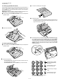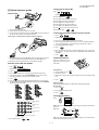
1
UX-178C/188C/108C/118C FO-175LU/375C SERVICE MANUAL No. 00ZUX178C/SME FACSIMILE UX-178 UX-188 UX-108 UX-118 FO-175 MODEL FO-375 Illustration: UX-178 Non Cutter model UX-108/118 FO-175 Cutter model UX-178/188 FO-375 CONTENTS CHAPTER 1. GENERAL DESCRIPTION [1] Specifications ............................................ [2] Operation panel......................................... [3] Transmittable documents .......................... [4] Installation ................................................. [5] Quick reference guide ............................... CHAPTER 5. CIRCUIT DESCRIPTION [1] Circuit description ...................................... 5-1 [2] Circuit description of control PWB ..............5-2 [3] Circuit description of TEL/LIU PWB .......... 5-8 [4] Circuit description of power supply PWB ............................ 5-11 [5] Circuit description of CIS unit ................... 5-11 1-1 1-2 1-3 1-4 1-7 CHAPTER 2. ADJUSTMENTS [1] Adjustments ............................................... 2-1 [2] Diagnostics and service soft switch .......... 2-2 [3] Troubleshooting ...................................... 2-17 [4] Error code table....................................... 2-18 CHAPTER 6. CIRCUIT SCHEMATICS AND PARTS LAYOUT [1] Control PWB circuit ................................... 6-1 [2] TEL/LIU PWB circuit ................................. 6-9 [3] Power supply PWB circuit ....................... 6-11 [4] Operation panel PWB circuit ................... 6-13 CHAPTER 3. MECHANISM BLOCKS [1] General description .................................. 3-1 [2] Disassembly and assembly procedures ....................................... 3-3 CHAPTER 7. OPERATION FLOWCHART [1] Protocol ..................................................... 7-1 [2] Power on sequence .................................. 7-2 CHAPTER 4. DIAGRAMS [1] Block diagram ............................................4-1 [2] Wiring diagram .......................................... 4-2 [3] Point-to-point diagram ............................... 4-3 CHAPTER 8. OTHERS [1] Service tools .............................................. 8-1 [2] IC signal name .......................................... 8-3 PARTS GUIDE Parts marked with " " is important for maintaining the safety of the set. Be sure to replace these parts with specified ones for maintaining the safety and performance of the set. SHARP CORPORATION 1-1 This document has been published to be used for after sales service only. The contents are subject to change without notice. UX-178C/188C/108C/118C FO-175LU/375C CAUTION FOR BATTERY REPLACEMENT (Danish) ADVARSEL ! Lithiumbatteri-Eksplosionsfare ved fejlagtig håndtering. Udskiftning må kun ske med batteri af samme fabrikat og type. Levér det brugte batteri tilbage til leverandoren. (English) Caution ! Danger of explosion if battery is incorrectly replaced. Replace only with the same or equivalent type recommended by the equipment manufacturer. Discard used batteries according to manufacturer’s instructions. (Finnish) VAROITUS Paristo voi räjähtää, jos se on virheellisesti asennettu. Vaihda paristo ainoastaan laitevalmistajan suosittelemaan tyyppiin. Hävitä käytetty paristo valmistajan ohjeiden mukaisesti. (French) ATTENTION Il y a danger d’explosion s’ il y a remplacement incorrect de la batterie. Remplacer uniquement avec une batterie du même type ou d’un type recommandé par le constructeur. Mettre au rébut les batteries usagées conformément aux instructions du fabricant. (Swedish) VARNING Explosionsfare vid felaktigt batteribyte. Använd samma batterityp eller en ekvivalent typ som rekommenderas av apparattillverkaren. Kassera använt batteri enligt fabrikantens instruktion. (German) Achtung Explosionsgefahr bei Verwendung inkorrekter Batterien. Als Ersatzbatterien dürfen nur Batterien vom gleichen Typ oder vom Hersteller empfohlene Batterien verwendet werden. Entsorgung der gebrauchten Batterien nur nach den vom Hersteller angegebenen Anweisungen. 1–2 UX-178C/188C/108C/118C FO-175LU/375C CHAPTER 1. GENERAL DESCRIPTION [1] Specifications Automatic dialing: Rapid Key Dialing: 10 numbers Speed Dialing: 20 numbers Fax paper: Initial starter roll (included with fax machine): 10 m (49 ft.) roll Recommended replacement roll: FO-40PRw 50 m (164 ft.) roll Automatic document feeder: 10 sheets max. Paper cutting method: UX-108/118/FO-175: Tear off by hand UX-178/188/FO-375: Automatic cutter Modem speed: 9600 bps with automatic fallback to 7200, 4800, or 2400 bps Transmission time* : Approx. 15 seconds (Sharp special mode) Display: 16-digit LCD display Reception modes: Auto/Manual/Answering machine (for connecting answering machine) Resolution: Horizontal: 8 dots/mm (203 pels/inch) Vertical: Standard: 3.85 lines/mm (98 lines/inch) Fine/Halftone: 7.7 lines/mm (196 lines/inch) Super fine: 15.4 lines/mm (391 lines/inch) Effective scanning width: 210 mm (8.3") max. Contrast control: Automatic/Dark selectable Copy function: Standard Telephone function: Standard (cannot be used if power fails) Power requirements: 120 V AC, 60 Hz Operating environment: 5 to 35°C (41 to 95°F) Humidity: Maximum: 85 % Power consumption: Stand-by: 6.0 W Maximum: 100 W Dimensions: Width: 308 mm (12.1") Depth: 256 mm (10.4") Height: 138 mm (5.4") Weight: UX-108/118/FO-175: Approx. 2.5 kg (5.5 lbs.) UX-178/UX-188/FO-375: Approx. 2.6 kg (5.7 lbs.) * Recording system: Thermal recording Halftone (grayscale): 64 levels Applicable telephone line: Public switched telephone network Compatibility: ITU-T (CCITT) G3 mode Configuration: Half-duplex, desktop transceiver Compression scheme: MH, MR, Sharp Scanning method: Sheet-feeder CIS (Contact Image Sensor) Effective recording width: 210 mm (8.3") max. Input document size: Automatic feeding: Width 148 to 216 mm (5.8 to 8.5") Length 140 to 279 mm (5.5 to 11") Manual feeding: Width 148 to 216 mm (5.8 to 8.5") Length 140 to 600 mm (5.5 to 23.6") Based on ITU-T (CCITT) Test Chart #1 at standard resolution in Sharp special mode, excluding time for protocol signals (i.e., ITU-T phase C time only). As a part of our policy of continuous improvement, SHARP reserves the right to make design and specification changes for procduct improvement without prior notice. The performance specifications figures indicated are nominal values of production units. There may be some deviation from these values in individual units. 1–1 UX-178C/188C/108C/118C FO-175LU/375C [2] Operation panel 1 2 3 RECEPTION MODE FUNCTION TEL FAX DOWN 5 4 6 7 RESOLUTION VOLUME UP A.M. ABC STOP DEF SPEED DIAL GHI JKL TUV 2 3 4 5 6 7 8 COPY/HELP REDIAL PQRS 1 MNO WXYZ HOLD/SEARCH START SPEAKER 9 8 9 10 11 12 10/POLL 13 14 15 10. REDIAL key 1. Display Press this key to automatically redial the last number dialed. This displays various messages and prompts during operation and programming. 11. SPEAKER key 2. PANEL RELEASE Press this key to hear the line and fax tones through the speaker when sending a document. Note: This is not a speakerphone. You must pick up the handset to talk with the other party. Pull this release toward you to open the operation panel. 3. RECEPTION MODE key Press this key to select the reception mode. An arrow in the display will point to the currently selected reception mode. 12. HOLD/SEARCH key Press this key to search for an automatic dialing number, or, during a phone conversation, press this key to put the other party on hold. 4. FUNCTION key Press this key to select various special function. 13. Rapid Dial keys 5. RESOLUTION key Press one of these keys to dial a fax or voice number automatically. (Note that you must attach the Rapid Key labels.) Press this key to adjust the resolution and contrast before sending or copying a document. 6. VOLUME keys 14. START key Press these keys to adjust the volume of the handset when the handset is lifted, the volume of the speaker when the SPEAKER key has been pressed, or the volume of the ringer at all other times. Press this key to send or receive a document. 15. COPY/HELP key When a document is in the feeder, press this key to make a copy. At any other time, press this key to print out the Help List, a quick refernce guide to the opeation of your fax. 7. STOP key Press this key to stop operations before they are completed. 8. Number keys Use these keys to dial numbers, and enter number and letters during number/name storing procedures. 9. SPEED DIAL key Press this key to dial a 2-digit Speed Dial number. 1–2 UX-178C/188C/108C/118C FO-175LU/375C [3] Transmittable documents 5. Automatic Document Feeder Capacity 1. Document Sizes Number of pages that can be placed into the feeder at anytime is as follows: Normal size width 148 – 216 mm Normal size: max. ADF 10 sheets length 140 – 279 mm Special size: single sheet only (manual feed) NOTES: (Max.) (Min.) 140mm 148mm • 600mm (Max.) Leter size 279mm When you need to send or copy more pages than the feeder limit, place additional pages in feeder when last page in feeder is being scanned. Place additional pages carefully and gently in feeder. If force is used, double-feeding or a document jam may result. 6. Readable Width & Length 216mm [Normal size] The readable width and length of a document are slightly smaller than the actual document size. 216mm [Special size] Note that characters or graphics outside the effective document scanning range will not be read. Use document carrier sheet for smaller documents. * • • With special sizes, only one sheet can be fed into the machine at a time. Insert next page into feeder as current page is being scanned. Readable width 210 mm, max. 2. Paper Thickness & Weight Normal size ADF 10 sheets Thickness 2.4 x 10⁻³ –4.7 x 10⁻³ inch (0.06–0.12 mm) Weight 0.15 x 10⁻³ lbs/inch2 (52–104g/m2 ) (14–28lbs) Thickness 4.7 x 10⁻³ –7.9 x 10⁻³ inch (0.12–0.20 mm) Weight 0.15 x 10⁻³ –0.20 x 10⁻³ lbs/inch2 (52–157 g/m2) Special size Readable width 3. Document Types • • Normal paper Documents handwritten in pencil (No. 2 lead or softer), fountain pen, ball-point pen, or felt-tipped pen can be transmitted. Documents of normal contrast duplicated by a copying machine can also be transmitted. • Diazo copy (blue print) • Carbon copy Readable length This is the length of the document sent minus 4 mm (0.16") from the top and bottom edges. 4mm(0.16") Diazo copy documents of a normal contrast may be transmitted. Readable length A carbon copy may be transmitted if its contrast is normal. 4mm(0.16") 4. Cautions on Transmitting Documents • Documents written in yellow, greenish yellow, or light blue ink cannot be transmitted. • Ink, glue, and correcting fluid on documents must be dry before the documents can be transmitted. • All clips, staples and pins must be removed from documents be-fore transmission. • Patched (taped) documents should be copied first on a copier and then the copies used for transmission. • All documents should be fanned before insertion into the feeder to prevent possible double feeds. 1–3 UX-178C/188C/108C/118C FO-175LU/375C 7. Use of Document Carrier Sheet TELEPHONE JACK A document carrier sheet must be used for the following documents. • Those with tears. A standard RJ11C telephone jack must be located near the machine. This is the telephone jack commonly used in most homes and offices. • • • Those smaller than size 140 mm (W) x 140 mm (L). Carbon-backed documents Make print straight across paper E.G. Place the document carrier in the document feeder with the clear film side down Plugging the fax machine into a jack which is not an RJ11C jack may result in damage to the machine or your telephone system. If you do not know what kind of jack you have, or needed to have one installed, contact the telephone company. 2. Connections 1 Connect the handset as shown and place it on the handset rest. ♦ Make sure the handset cord goes into the unmarked jack on the side of the machine! ♦ Use the handset to make ordinary phone calls, or to transmit and receive documents manually. Direction of insertion NOTE: To transmit a carbon-backed document, insert a white sheet of paper between the carbon back of the document and the document carrier. • Those containing an easily separable writing substance (e.g., tracing paper written on with a soft, heavy lead pencil). NOTES: • When using the document carrier, carefully read the instructions written on the back. • If the document carrier is dirty, clean it with a soft, moist cloth, and then dry it before using for transmission. • 2 Plug the power cord into a 120 V, 60 Hz, grounded (3-prong) AC outlet. ♦ Caution: Do not plug the power cord into any other kind of outlet. This will damage the machine and is not covered under the warranty. Do not place more than one document in the carrier at a time. ♦ The machine does not have a power on/off switch, so the power is turned on and off by simply plugging or unplugging the power cord. [4] Installation 1. Site selection Note: If your area experiences a high incidence of lightning or power surges, we recommend that you install surge protectors for the power and telephone lines. Surge protectors can be purchased from your dealer or at most telephone specialty stores. Take the following points into consideration when selecting a site for this model. ENVIRONMENT • • The machine must be installed on a level surface. • Provide easy access to the front, back, and sides of the machine. In particular, keep the area in front of the machine clear, or the original document may jam as it comes out after scanning. • • The temperature should be between 5° and 35°C. Keep the machine away from air conditioners, heaters, direct sunlight, and dust. 3 Insert one end of the telephone line cord into the "TEL. LINE" jack. Insert the other end into a standard (RJ11C) single-line telephone wall jack. The humidity should be between 30% and 85% (without condensation). ♦ Be sure to insert the telephone line cord into the "TEL. LINE" jack. Do not insert into the "TEL. SET" jack. ELECTRICITY 120V, 60Hz, grounded (3-prong) AC outlet is required. Caution! • Connection to a power source other than that specified will cause damage to the equipment and is not covered under the warranty. • If your area experiences a high incidence of lightning or power surges, we recommend that you install a surge protector for the power and telephone lines. Surge protectors can be purchased at most telephone specialty stores. If the machine is moved from a cold to a warm place... TE SEL. T T EL LI . NE If the machine is moved from a cold to a warm place, it is possible that the reading glass may fog up, preventing proper scanning of documents for transmission. To remove the fog, turn on the power and wait approximately 2 hours before using the machine. 1–4 UX-178C/188C/108C/118C FO-175LU/375C 4 Unwrap the roll of fax paper and place it in the compartment. 3. Original document support 1 Rotate the original document support so that it points straight out. • Important: The roll must be placed so that the leading edge of the paper unrolls as shown. (The paper is only coated on one side for printing. If the roll is placed backwards, the paper will come out blank after printing.) NO! YES 4. Loading the fax paper • Your fax machine prints incoming faxes on a special kind of paper called thermal paper. • The fax’s print head creates text and images by applying heat to the thermal paper. Note: The power must be on (plug in the power cord) when loading fax paper in the fax machine. 1 Pull the release marked PANEL RELEASE toward you and open the operation panel. 5 Insert the leading edge of the paper into the paper inlet. Continue to push the paper through the inlet until it comes out of the opening in the front of the fax. Paper inlet 2 Remove the packing paper from the paper compartment. Remove cardboard and tape UX-108/118/FO-175: Remove the tape The paper will reappear here. Make sure it is aligned between the arrows on each side of the guide, and then passes under the plate and out the front of the fax. 6 Close the operation panel, making sure it clicks into place. 2 3 Make sure the ends of the guide wire are inserted in the holes. (If the Click! guide wire is not inserted correctly, out-of-paper detection will not be possible.). 1 7 UX-108/118/FO-175: A short length of the fax paper will feed out. Grasp the paper by the edge and pull upward to tear it off. UX-178/UX-188/FO-375: A short length of the fax paper will feed out and be cut off. (If this doesn’t happen, repeat the loading procedure.) Note: The UX-178/UX-188/FO-375 has a built-in anti-curl mechanism that will help to reduce paper curling problems. The anticurl mechanism is more effective at the beginning of the paper roll and less effective towards the end. 1–5 UX-178C/188C/108C/118C FO-175LU/375C 3 Cut off the wrinkled part of the paper. 4. Clearing a jammed document If the original document doesn’t feed properly during transmission or copying, or DOCUMENT JAMMED appears in the display, first try pressing the START key. If the document doesn’t feed out, open the operation panel and remove it. Important: Do not try to remove a document without opening the operation panel. This may damage the feeder mechanism. 1 Pull the release marked PANEL RELEASE toward you and open the operation panel. 4 Reload the paper. • Jammed fax paper is often caused by improper loading. Be sure to carefully follow the instructions for paper loading given in "Loading the Fax Paper" in page 1-5. 2 Remove the document. 5 If the display still shows PAPER JAMMED (UX-178/188/FO-375 only) If the display still shows PAPER JAMMED after you press the START key in Step 2 above, the cutter is still engaged in the cutting position. To open the cutter, turn the fax up on its rear end and insert any long, rod-like object with a flat or blunt end into the hole marked CUTTER RESET. Continue to push the rod in until you feel it move a lever inside the machine. 5. Clearing jammed fax paper 1 Pull the release marked PANEL RELEASE toward you and open the operation panel. TER CUT T E RES 2 Remove the paper roll. • • ABC UX-178/188/FO-375: If any pieces of paper are stuck in the cutter, remove them with caution. DEF SPEED DIAL UX-178/188/FO-375: Press the START key to reset the cutter. GHI JKL MNO Press this key to delete the letter highlighted by the cursor. REDIAL Press this key to move the cursor to the left. PQRS TUV WXYZ HOLD/SEARCH Press this key to change case. SPEAKER Press this key to move the cursor to the right. Press either key repeatedly to select one of the following symbols. 1–6 UX-178C/188C/108C/118C FO-175LU/375C SETTING THE DATE AND TIME [5] Quick reference guide Press: FUNCTION 3 1 INSTALLATION Display: DATE & TIME SET 2 START Press the START key: Enter two digits for the Month (01 through 12). TEL SET. Enter two digits for the Day (01 through 31). TEL LIN . E Enter four digits for the Year (EX: 1998). Enter two digits for the Hour (01 through 12). 3 Enter two digits for the Minute (00 through 59). Press the " " key for A.M. or the "#" key for P.M. START When finished, press: 1. Connect the handset as shown. STOP 2. Plug the power cord into a grounded, 120 V outlet. STORING AND CLEARING NUMBERS FOR AUTO DIALING 3. Plug one end of the telephone line into the "TEL. LINE" jack on the rear of the fax, and the other end into your telephone wall jack. FUNCTION 1. Press: 3 Connecting an answering machine and/or extension telephone Display shows: FAX/TEL # MODE 2. Press "1" to store a number or "2" to clear a number. TEL SET. 3. Enter a 2-digit Speed Dial number (from "01" to "10" for Rapid Key Dialing, or 11 to 30 for Speed Dialing). (If you are clearing a number, go to Step 7.) TEL LIN . E 4. Enter the full telephone/fax number. START 5. Press: 6. Enter the name of the location by pressing number keys (max. of 20 characters). (Refer to the letter entry table in ENTERING YOUR NAME AND NUMBER.) START 7. Press: SENDING DOCUMENTS 1. Remove the seal covering the "TEL. SET" jack on the rear of the fax. Connect an extension telephone or answering machine to the "TEL. SET" jack. Place your document (up to 10 pages) face down in the document feeder. 2. If desired, connect an extension phone to the answering machine. ENTERING YOUR NAME AND NUMBER 1. Press: STOP FUNCTION 3 Display shows: OWN NUMBER SET 2. Press: Normal Dialing 1. Lift the handset or press START SPEAKER 3. Enter your fax number (max. of 20 digits) by pressing the number keys. 2. Dial the fax number. ♦ If you make a mistake, press the HOLD/SEARCH key to move the cursor back to the mistake, then enter the correct number or letter. 3. Wait for the reception tone (if a person answers, ask them to press their Start key). 4. Press: START 4. Press: 5. Enter your name by pressing the appropriate number keys as shown below. ♦ To enter two letters in succession that require the same key, press the SPEAKER key after entering the first letter. START Rapid Key Dialing Press the appropriate Rapid Key. Transmission will begin automatically. A= J= T= B= K= U= Speed Dialing C= L= V= 1. Press: D= M= W= E= N= X= F= O= Y= G= P= Z= H= Q= SPACE = I= R= SPEED DIAL 2. Enter 2-digit Speed Dial number. 3. Press: START RECEIVING DOCUMENTS TEL Press: S= RECEPTION MODE A.M. TEL DEF ABC A.M. PQRS TEL REDIAL A.M. Upper/lower case shift key FAX mode: The fax automatically answers on four rings and receives the incoming document. WXYZ TUV FAX FEB 1 1998 MNO JKL FAX FEB 1 1998 SPEED DIAL Deletes highlighted letter GHI FAX FEB 1 1998 HOLD/SEARCH Moves cuesor to the left START TEL mode: Fax tone SPEAKER Moves cuesor to the right RECEIVING Press either key one or more times to select and enter a symbol. START A.M. mode: Select this mode when an answering machine is connected to the fax and the answering machine is turned on. STOP 6. When finished, press: 1–7