1
service
output finishing devices:
hp LaserJet multifunction finisher, 3,000-sheet
stapler/stacker, 3,000-sheet stacker,
and 8-bin mailbox
service supplement __________
Copyright and License
Trademark Credits
© 2004 Copyright HewlettPackard Development Company,
LP
Adobe® and PostScript® are
trademarks of Adobe Systems
Incorporated.
Reproduction, adaptation or
translation without prior written
permission is prohibited, except
as allowed under the copyright
laws.
MS-DOS® is a U.S. registered
trademark of Microsoft
Corporation.
Part number: Q5693-90002
Edition 1, 9/2004
The information contained herein
is subject to change without
notice.
The only warranties for HP
products and services are set
forth in the express warranty
statements accompanying such
products and services. Nothing
herein should be construed as
constituting an additional
warranty. HP shall not be liable
for technical or editorial errors or
omissions contained herein.
ENERGY STAR® is a U.S.
registered service mark of the
United States Environmental
Protection Agency.
Contents
1 Product information
Product features . . . . . . . . . . . . . . . . . . . . . . . . . . . . . . . . . . . . . . . . . . . . . . . . . . . . . . . . .
Multifunction finisher (C8088A/C8088B) . . . . . . . . . . . . . . . . . . . . . . . . . . . . . . . . . . . . .
3,000-sheet stapler/stacker (C8085A) . . . . . . . . . . . . . . . . . . . . . . . . . . . . . . . . . . . . . .
3,000-sheet stacker (C8084A) . . . . . . . . . . . . . . . . . . . . . . . . . . . . . . . . . . . . . . . . . . . .
8-bin mailbox (Q5693A) . . . . . . . . . . . . . . . . . . . . . . . . . . . . . . . . . . . . . . . . . . . . . . . . .
Identification . . . . . . . . . . . . . . . . . . . . . . . . . . . . . . . . . . . . . . . . . . . . . . . . . . . . . . . . . . . .
Multifunction finisher . . . . . . . . . . . . . . . . . . . . . . . . . . . . . . . . . . . . . . . . . . . . . . . . . . .
3,000-sheet stapler/stacker . . . . . . . . . . . . . . . . . . . . . . . . . . . . . . . . . . . . . . . . . . . . . .
3,000-sheet stacker . . . . . . . . . . . . . . . . . . . . . . . . . . . . . . . . . . . . . . . . . . . . . . . . . . . .
8-bin mailbox. . . . . . . . . . . . . . . . . . . . . . . . . . . . . . . . . . . . . . . . . . . . . . . . . . . . . . . . . .
Product overview . . . . . . . . . . . . . . . . . . . . . . . . . . . . . . . . . . . . . . . . . . . . . . . . . . . . . . . .
Multifunction finisher . . . . . . . . . . . . . . . . . . . . . . . . . . . . . . . . . . . . . . . . . . . . . . . . . . .
3,000-sheet stapler/stacker . . . . . . . . . . . . . . . . . . . . . . . . . . . . . . . . . . . . . . . . . . . . . .
3,000-sheet stacker . . . . . . . . . . . . . . . . . . . . . . . . . . . . . . . . . . . . . . . . . . . . . . . . . . . .
8-bin mailbox. . . . . . . . . . . . . . . . . . . . . . . . . . . . . . . . . . . . . . . . . . . . . . . . . . . . . . . . . .
Specifications . . . . . . . . . . . . . . . . . . . . . . . . . . . . . . . . . . . . . . . . . . . . . . . . . . . . . . . . . . .
Multifunction finisher . . . . . . . . . . . . . . . . . . . . . . . . . . . . . . . . . . . . . . . . . . . . . . . . . . . .
3,000-sheet stapler/stacker . . . . . . . . . . . . . . . . . . . . . . . . . . . . . . . . . . . . . . . . . . . . . .
3,000-sheet stacker . . . . . . . . . . . . . . . . . . . . . . . . . . . . . . . . . . . . . . . . . . . . . . . . . . . .
8-bin mailbox. . . . . . . . . . . . . . . . . . . . . . . . . . . . . . . . . . . . . . . . . . . . . . . . . . . . . . . . . .
Regulatory information . . . . . . . . . . . . . . . . . . . . . . . . . . . . . . . . . . . . . . . . . . . . . . . . . . . .
Declaration of Conformity—multifunction finisher . . . . . . . . . . . . . . . . . . . . . . . . . . . . .
Declaration of Conformity—3,000-sheet stapler/stacker . . . . . . . . . . . . . . . . . . . . . . . .
Declaration of Conformity—3,000-sheet stacker . . . . . . . . . . . . . . . . . . . . . . . . . . . . . .
Declaration of Conformity—8-bin mailbox . . . . . . . . . . . . . . . . . . . . . . . . . . . . . . . . . . .
Service approach . . . . . . . . . . . . . . . . . . . . . . . . . . . . . . . . . . . . . . . . . . . . . . . . . . . . . . .
Parts and supplies . . . . . . . . . . . . . . . . . . . . . . . . . . . . . . . . . . . . . . . . . . . . . . . . . . . . .
Exchange program . . . . . . . . . . . . . . . . . . . . . . . . . . . . . . . . . . . . . . . . . . . . . . . . . . . . .
Warranty . . . . . . . . . . . . . . . . . . . . . . . . . . . . . . . . . . . . . . . . . . . . . . . . . . . . . . . . . . . . .
16
16
17
17
18
19
19
20
21
22
23
23
25
26
27
28
28
29
30
31
32
32
33
34
35
36
36
36
36
2 Installation
Environmental requirements . . . . . . . . . . . . . . . . . . . . . . . . . . . . . . . . . . . . . . . . . . . . . . .
Physical requirements . . . . . . . . . . . . . . . . . . . . . . . . . . . . . . . . . . . . . . . . . . . . . . . . . . . .
Multifunction finisher . . . . . . . . . . . . . . . . . . . . . . . . . . . . . . . . . . . . . . . . . . . . . . . . . . .
3,000-sheet stapler/stacker and 3,000-sheet stacker . . . . . . . . . . . . . . . . . . . . . . . . . .
8-bin mailbox . . . . . . . . . . . . . . . . . . . . . . . . . . . . . . . . . . . . . . . . . . . . . . . . . . . . . . . . .
38
39
39
40
41
3 Operation
Supported media . . . . . . . . . . . . . . . . . . . . . . . . . . . . . . . . . . . . . . . . . . . . . . . . . . . . . . . .
Multifunction finisher . . . . . . . . . . . . . . . . . . . . . . . . . . . . . . . . . . . . . . . . . . . . . . . . . . .
3,000-sheet stapler/stacker . . . . . . . . . . . . . . . . . . . . . . . . . . . . . . . . . . . . . . . . . . . . . .
3,000-sheet stacker . . . . . . . . . . . . . . . . . . . . . . . . . . . . . . . . . . . . . . . . . . . . . . . . . . . .
8-bin mailbox. . . . . . . . . . . . . . . . . . . . . . . . . . . . . . . . . . . . . . . . . . . . . . . . . . . . . . . . . .
Using media . . . . . . . . . . . . . . . . . . . . . . . . . . . . . . . . . . . . . . . . . . . . . . . . . . . . . . . . . . . .
Multifunction finisher . . . . . . . . . . . . . . . . . . . . . . . . . . . . . . . . . . . . . . . . . . . . . . . . . . .
3,000-sheet stapler/stacker. . . . . . . . . . . . . . . . . . . . . . . . . . . . . . . . . . . . . . . . . . . . . . .
44
44
46
46
47
48
48
50
Contents 3
4 Maintenance
Cleaning the outside of the product . . . . . . . . . . . . . . . . . . . . . . . . . . . . . . . . . . . . . . . . . . 52
Cleaning inside the product . . . . . . . . . . . . . . . . . . . . . . . . . . . . . . . . . . . . . . . . . . . . . . . . 52
5 Theory of operation
Power-on sequence . . . . . . . . . . . . . . . . . . . . . . . . . . . . . . . . . . . . . . . . . . . . . . . . . . . . . .
Multifunction finisher . . . . . . . . . . . . . . . . . . . . . . . . . . . . . . . . . . . . . . . . . . . . . . . . . . . .
3,000-sheet stapler/stacker . . . . . . . . . . . . . . . . . . . . . . . . . . . . . . . . . . . . . . . . . . . . . .
3,000-sheet stacker . . . . . . . . . . . . . . . . . . . . . . . . . . . . . . . . . . . . . . . . . . . . . . . . . . . .
8-bin mailbox . . . . . . . . . . . . . . . . . . . . . . . . . . . . . . . . . . . . . . . . . . . . . . . . . . . . . . . . .
Basic operation . . . . . . . . . . . . . . . . . . . . . . . . . . . . . . . . . . . . . . . . . . . . . . . . . . . . . . . . .
Multifunction finisher . . . . . . . . . . . . . . . . . . . . . . . . . . . . . . . . . . . . . . . . . . . . . . . . . . . .
Offset specifications . . . . . . . . . . . . . . . . . . . . . . . . . . . . . . . . . . . . . . . . . . . . . . . . . . . .
3,000-sheet stapler/stacker . . . . . . . . . . . . . . . . . . . . . . . . . . . . . . . . . . . . . . . . . . . . . . .
Offset specifications . . . . . . . . . . . . . . . . . . . . . . . . . . . . . . . . . . . . . . . . . . . . . . . . . . . .
3,000-sheet stacker. . . . . . . . . . . . . . . . . . . . . . . . . . . . . . . . . . . . . . . . . . . . . . . . . . . . .
Offset specifications . . . . . . . . . . . . . . . . . . . . . . . . . . . . . . . . . . . . . . . . . . . . . . . . . . . .
8-bin mailbox . . . . . . . . . . . . . . . . . . . . . . . . . . . . . . . . . . . . . . . . . . . . . . . . . . . . . . . . . .
Electric circuitry . . . . . . . . . . . . . . . . . . . . . . . . . . . . . . . . . . . . . . . . . . . . . . . . . . . . . . . . .
Power supply . . . . . . . . . . . . . . . . . . . . . . . . . . . . . . . . . . . . . . . . . . . . . . . . . . . . . . . . . . .
Multifunction finisher . . . . . . . . . . . . . . . . . . . . . . . . . . . . . . . . . . . . . . . . . . . . . . . . . . . .
3,000-sheet stapler/stacker . . . . . . . . . . . . . . . . . . . . . . . . . . . . . . . . . . . . . . . . . . . . . .
3,000-sheet stacker. . . . . . . . . . . . . . . . . . . . . . . . . . . . . . . . . . . . . . . . . . . . . . . . . . . . .
8-bin mailbox . . . . . . . . . . . . . . . . . . . . . . . . . . . . . . . . . . . . . . . . . . . . . . . . . . . . . . . . . .
Motors, solenoids, and clutches . . . . . . . . . . . . . . . . . . . . . . . . . . . . . . . . . . . . . . . . . . . . .
Multifunction finisher . . . . . . . . . . . . . . . . . . . . . . . . . . . . . . . . . . . . . . . . . . . . . . . . . . . .
8-bin mailbox . . . . . . . . . . . . . . . . . . . . . . . . . . . . . . . . . . . . . . . . . . . . . . . . . . . . . . . . . .
Sensors . . . . . . . . . . . . . . . . . . . . . . . . . . . . . . . . . . . . . . . . . . . . . . . . . . . . . . . . . . . . . . .
Multifunction finisher . . . . . . . . . . . . . . . . . . . . . . . . . . . . . . . . . . . . . . . . . . . . . . . . . . . .
3,000-sheet stapler/stacker . . . . . . . . . . . . . . . . . . . . . . . . . . . . . . . . . . . . . . . . . . . . . . .
3,000-sheet stacker. . . . . . . . . . . . . . . . . . . . . . . . . . . . . . . . . . . . . . . . . . . . . . . . . . . . .
8-bin mailbox . . . . . . . . . . . . . . . . . . . . . . . . . . . . . . . . . . . . . . . . . . . . . . . . . . . . . . . . . .
54
54
54
54
55
56
56
58
62
65
66
68
69
73
74
74
74
74
75
76
76
77
78
78
83
84
85
6 Removal and replacement
Introduction. . . . . . . . . . . . . . . . . . . . . . . . . . . . . . . . . . . . . . . . . . . . . . . . . . . . . . . . . . . . . 89
Removal and replacement strategy . . . . . . . . . . . . . . . . . . . . . . . . . . . . . . . . . . . . . . . . 89
Electrostatic discharge . . . . . . . . . . . . . . . . . . . . . . . . . . . . . . . . . . . . . . . . . . . . . . . . . . 89
Required tools . . . . . . . . . . . . . . . . . . . . . . . . . . . . . . . . . . . . . . . . . . . . . . . . . . . . . . . . . 89
Before performing service . . . . . . . . . . . . . . . . . . . . . . . . . . . . . . . . . . . . . . . . . . . . . . . . 90
Multifunction finisher external doors and covers . . . . . . . . . . . . . . . . . . . . . . . . . . . . . . . . 91
Stapler door . . . . . . . . . . . . . . . . . . . . . . . . . . . . . . . . . . . . . . . . . . . . . . . . . . . . . . . . . . 91
Product-release handle . . . . . . . . . . . . . . . . . . . . . . . . . . . . . . . . . . . . . . . . . . . . . . . . . 92
Folding knob . . . . . . . . . . . . . . . . . . . . . . . . . . . . . . . . . . . . . . . . . . . . . . . . . . . . . . . . . . 94
Handle-mounting gear . . . . . . . . . . . . . . . . . . . . . . . . . . . . . . . . . . . . . . . . . . . . . . . . . . 95
Front cover . . . . . . . . . . . . . . . . . . . . . . . . . . . . . . . . . . . . . . . . . . . . . . . . . . . . . . . . . . . 96
Back cover . . . . . . . . . . . . . . . . . . . . . . . . . . . . . . . . . . . . . . . . . . . . . . . . . . . . . . . . . . . 98
Upper panel assembly (top door) . . . . . . . . . . . . . . . . . . . . . . . . . . . . . . . . . . . . . . . . . . 99
Internal-path cover (dispose subcover) . . . . . . . . . . . . . . . . . . . . . . . . . . . . . . . . . . . . 100
Foot cover . . . . . . . . . . . . . . . . . . . . . . . . . . . . . . . . . . . . . . . . . . . . . . . . . . . . . . . . . . 101
Multifunction finisher assemblies . . . . . . . . . . . . . . . . . . . . . . . . . . . . . . . . . . . . . . . . . . . 102
Paper-guide wire . . . . . . . . . . . . . . . . . . . . . . . . . . . . . . . . . . . . . . . . . . . . . . . . . . . . . 102
Product-attachment latch . . . . . . . . . . . . . . . . . . . . . . . . . . . . . . . . . . . . . . . . . . . . . . . 103
Stapling unit . . . . . . . . . . . . . . . . . . . . . . . . . . . . . . . . . . . . . . . . . . . . . . . . . . . . . . . . . 104
Aligner racks . . . . . . . . . . . . . . . . . . . . . . . . . . . . . . . . . . . . . . . . . . . . . . . . . . . . . . . . . 105
Booklet bin-full sensor flag (main lever weight assembly) . . . . . . . . . . . . . . . . . . . . . . 106
Paper deflector (deflector weight) . . . . . . . . . . . . . . . . . . . . . . . . . . . . . . . . . . . . . . . . 107
Anti-static brush . . . . . . . . . . . . . . . . . . . . . . . . . . . . . . . . . . . . . . . . . . . . . . . . . . . . . . 109
4 Contents
ENWW
Stacker bin . . . . . . . . . . . . . . . . . . . . . . . . . . . . . . . . . . . . . . . . . . . . . . . . . . . . . . . . . . 110
Booklet bin . . . . . . . . . . . . . . . . . . . . . . . . . . . . . . . . . . . . . . . . . . . . . . . . . . . . . . . . . . 111
Stapling-door switch . . . . . . . . . . . . . . . . . . . . . . . . . . . . . . . . . . . . . . . . . . . . . . . . . . . 113
Interlock switch . . . . . . . . . . . . . . . . . . . . . . . . . . . . . . . . . . . . . . . . . . . . . . . . . . . . . . . 114
Flipper assembly . . . . . . . . . . . . . . . . . . . . . . . . . . . . . . . . . . . . . . . . . . . . . . . . . . . . . . 115
Folding mechanism . . . . . . . . . . . . . . . . . . . . . . . . . . . . . . . . . . . . . . . . . . . . . . . . . . . . 117
User LED PCA . . . . . . . . . . . . . . . . . . . . . . . . . . . . . . . . . . . . . . . . . . . . . . . . . . . . . . . 120
Controller PCA . . . . . . . . . . . . . . . . . . . . . . . . . . . . . . . . . . . . . . . . . . . . . . . . . . . . . . . 121
Service LED PCA . . . . . . . . . . . . . . . . . . . . . . . . . . . . . . . . . . . . . . . . . . . . . . . . . . . . . 123
Power supply . . . . . . . . . . . . . . . . . . . . . . . . . . . . . . . . . . . . . . . . . . . . . . . . . . . . . . . . . 124
Jet-Link cable (interface cable) . . . . . . . . . . . . . . . . . . . . . . . . . . . . . . . . . . . . . . . . . . . 125
Adjustable casters (left side) . . . . . . . . . . . . . . . . . . . . . . . . . . . . . . . . . . . . . . . . . . . . . 126
Stationary extended caster (back right) . . . . . . . . . . . . . . . . . . . . . . . . . . . . . . . . . . . . . 127
Stationary caster (front right) . . . . . . . . . . . . . . . . . . . . . . . . . . . . . . . . . . . . . . . . . . . . . 128
3,000-sheet stapler/stacker and 3,000-sheet stacker external doors and covers . . . . . . . 129
Face-up bin . . . . . . . . . . . . . . . . . . . . . . . . . . . . . . . . . . . . . . . . . . . . . . . . . . . . . . . . . . 129
Stapler/stacker bin (stapler/stacker only) or stacker bin (stacker only) . . . . . . . . . . . . . 129
Back inner cover and front inner cover . . . . . . . . . . . . . . . . . . . . . . . . . . . . . . . . . . . . . 130
Front cover . . . . . . . . . . . . . . . . . . . . . . . . . . . . . . . . . . . . . . . . . . . . . . . . . . . . . . . . . . 131
Back cover . . . . . . . . . . . . . . . . . . . . . . . . . . . . . . . . . . . . . . . . . . . . . . . . . . . . . . . . . . 132
Foot cover . . . . . . . . . . . . . . . . . . . . . . . . . . . . . . . . . . . . . . . . . . . . . . . . . . . . . . . . . . . 134
Controller PCA cover . . . . . . . . . . . . . . . . . . . . . . . . . . . . . . . . . . . . . . . . . . . . . . . . . . . 135
Door assembly . . . . . . . . . . . . . . . . . . . . . . . . . . . . . . . . . . . . . . . . . . . . . . . . . . . . . . . . 136
3,000-sheet stapler/stacker and 3,000-sheet stacker assemblies. . . . . . . . . . . . . . . . . . . 137
Flipper assembly . . . . . . . . . . . . . . . . . . . . . . . . . . . . . . . . . . . . . . . . . . . . . . . . . . . . . . 137
Paper-path assembly . . . . . . . . . . . . . . . . . . . . . . . . . . . . . . . . . . . . . . . . . . . . . . . . . . 138
Accumulator wings (stapler/stacker only). . . . . . . . . . . . . . . . . . . . . . . . . . . . . . . . . . . . 139
Paper-stop clips . . . . . . . . . . . . . . . . . . . . . . . . . . . . . . . . . . . . . . . . . . . . . . . . . . . . . . 140
Accumulator assembly (stapler/stacker only). . . . . . . . . . . . . . . . . . . . . . . . . . . . . . . . . 141
Carriage assembly (stapler/stacker only) . . . . . . . . . . . . . . . . . . . . . . . . . . . . . . . . . . . . 144
Offset module (stacker only) . . . . . . . . . . . . . . . . . . . . . . . . . . . . . . . . . . . . . . . . . . . . . 146
Stapler (stapler/stacker only) . . . . . . . . . . . . . . . . . . . . . . . . . . . . . . . . . . . . . . . . . . . . . 148
Controller PCA . . . . . . . . . . . . . . . . . . . . . . . . . . . . . . . . . . . . . . . . . . . . . . . . . . . . . . . 150
Power supply . . . . . . . . . . . . . . . . . . . . . . . . . . . . . . . . . . . . . . . . . . . . . . . . . . . . . . . . . 152
LED PCA . . . . . . . . . . . . . . . . . . . . . . . . . . . . . . . . . . . . . . . . . . . . . . . . . . . . . . . . . . . . 153
Interlock switch . . . . . . . . . . . . . . . . . . . . . . . . . . . . . . . . . . . . . . . . . . . . . . . . . . . . . . . 154
Safety-switch assembly (stapler/stacker only) . . . . . . . . . . . . . . . . . . . . . . . . . . . . . . . . 155
Optical sensors . . . . . . . . . . . . . . . . . . . . . . . . . . . . . . . . . . . . . . . . . . . . . . . . . . . . . . . 156
Cable assembly . . . . . . . . . . . . . . . . . . . . . . . . . . . . . . . . . . . . . . . . . . . . . . . . . . . . . . . 158
Casters . . . . . . . . . . . . . . . . . . . . . . . . . . . . . . . . . . . . . . . . . . . . . . . . . . . . . . . . . . . . . 159
8-bin mailbox external doors and covers. . . . . . . . . . . . . . . . . . . . . . . . . . . . . . . . . . . . . . 160
Bubbled cover . . . . . . . . . . . . . . . . . . . . . . . . . . . . . . . . . . . . . . . . . . . . . . . . . . . . . . . . 160
Front cover . . . . . . . . . . . . . . . . . . . . . . . . . . . . . . . . . . . . . . . . . . . . . . . . . . . . . . . . . . . 161
Back cover . . . . . . . . . . . . . . . . . . . . . . . . . . . . . . . . . . . . . . . . . . . . . . . . . . . . . . . . . . . 162
Top cover . . . . . . . . . . . . . . . . . . . . . . . . . . . . . . . . . . . . . . . . . . . . . . . . . . . . . . . . . . . . 164
Cable channel . . . . . . . . . . . . . . . . . . . . . . . . . . . . . . . . . . . . . . . . . . . . . . . . . . . . . . . . 166
Paper bins and blind cover . . . . . . . . . . . . . . . . . . . . . . . . . . . . . . . . . . . . . . . . . . . . . . 167
8-bin mailbox assemblies . . . . . . . . . . . . . . . . . . . . . . . . . . . . . . . . . . . . . . . . . . . . . . . . . 169
Power supply . . . . . . . . . . . . . . . . . . . . . . . . . . . . . . . . . . . . . . . . . . . . . . . . . . . . . . . . . 169
Flipper assembly . . . . . . . . . . . . . . . . . . . . . . . . . . . . . . . . . . . . . . . . . . . . . . . . . . . . . . 170
Delivery head motor . . . . . . . . . . . . . . . . . . . . . . . . . . . . . . . . . . . . . . . . . . . . . . . . . . . . 174
Transport belt motor . . . . . . . . . . . . . . . . . . . . . . . . . . . . . . . . . . . . . . . . . . . . . . . . . . . . 175
Input paper guide . . . . . . . . . . . . . . . . . . . . . . . . . . . . . . . . . . . . . . . . . . . . . . . . . . . . . . 177
Face-up full lever . . . . . . . . . . . . . . . . . . . . . . . . . . . . . . . . . . . . . . . . . . . . . . . . . . . . . . 178
Rollers kit . . . . . . . . . . . . . . . . . . . . . . . . . . . . . . . . . . . . . . . . . . . . . . . . . . . . . . . . . . . . 179
Magnets assembly . . . . . . . . . . . . . . . . . . . . . . . . . . . . . . . . . . . . . . . . . . . . . . . . . . . . . 180
Metal tape and housing assembly . . . . . . . . . . . . . . . . . . . . . . . . . . . . . . . . . . . . . . . . . 181
Controller PCA . . . . . . . . . . . . . . . . . . . . . . . . . . . . . . . . . . . . . . . . . . . . . . . . . . . . . . . . 183
Anticurl strings . . . . . . . . . . . . . . . . . . . . . . . . . . . . . . . . . . . . . . . . . . . . . . . . . . . . . . . . 185
ENWW
Contents 5
Delivery head assembly . . . . . . . . . . . . . . . . . . . . . . . . . . . . . . . . . . . . . . . . . . . . . . . .
Interlock switch . . . . . . . . . . . . . . . . . . . . . . . . . . . . . . . . . . . . . . . . . . . . . . . . . . . . . . .
Diagnostic LED PCA . . . . . . . . . . . . . . . . . . . . . . . . . . . . . . . . . . . . . . . . . . . . . . . . . .
User status LED PCA . . . . . . . . . . . . . . . . . . . . . . . . . . . . . . . . . . . . . . . . . . . . . . . . . .
Adjustable, fixed, and extended fixed casters . . . . . . . . . . . . . . . . . . . . . . . . . . . . . . . .
Attachment assembly . . . . . . . . . . . . . . . . . . . . . . . . . . . . . . . . . . . . . . . . . . . . . . . . . .
187
190
191
192
193
194
7 Troubleshooting
Understanding the troubleshooting process . . . . . . . . . . . . . . . . . . . . . . . . . . . . . . . . . .
Preliminary operating checks . . . . . . . . . . . . . . . . . . . . . . . . . . . . . . . . . . . . . . . . . . . .
Troubleshooting flowchart . . . . . . . . . . . . . . . . . . . . . . . . . . . . . . . . . . . . . . . . . . . . . . .
Troubleshooting by using the event log and the control panel messages . . . . . . . . . . . .
Event log . . . . . . . . . . . . . . . . . . . . . . . . . . . . . . . . . . . . . . . . . . . . . . . . . . . . . . . . . . .
Event log messages . . . . . . . . . . . . . . . . . . . . . . . . . . . . . . . . . . . . . . . . . . . . . . . . . . .
Device error conditions . . . . . . . . . . . . . . . . . . . . . . . . . . . . . . . . . . . . . . . . . . . . . . . . .
Control panel messages . . . . . . . . . . . . . . . . . . . . . . . . . . . . . . . . . . . . . . . . . . . . . . . .
Multifunction finisher control panel and event log messages . . . . . . . . . . . . . . . . . . . .
3,000-sheet stapler/stacker control panel and event log messages . . . . . . . . . . . . . . .
3,000-sheet stacker control panel and event log messages . . . . . . . . . . . . . . . . . . . . .
8-bin mailbox control panel and event log messages . . . . . . . . . . . . . . . . . . . . . . . . . .
Troubleshooting jams . . . . . . . . . . . . . . . . . . . . . . . . . . . . . . . . . . . . . . . . . . . . . . . . . . . .
Jams . . . . . . . . . . . . . . . . . . . . . . . . . . . . . . . . . . . . . . . . . . . . . . . . . . . . . . . . . . . . . . .
Clearing jams . . . . . . . . . . . . . . . . . . . . . . . . . . . . . . . . . . . . . . . . . . . . . . . . . . . . . . . .
Troubleshooting media problems . . . . . . . . . . . . . . . . . . . . . . . . . . . . . . . . . . . . . . . . . . .
Determine the problem source: print media or output device . . . . . . . . . . . . . . . . . . . .
Isolate a paper path. . . . . . . . . . . . . . . . . . . . . . . . . . . . . . . . . . . . . . . . . . . . . . . . . . . .
Isolate a media brand . . . . . . . . . . . . . . . . . . . . . . . . . . . . . . . . . . . . . . . . . . . . . . . . . .
Isolate a media type . . . . . . . . . . . . . . . . . . . . . . . . . . . . . . . . . . . . . . . . . . . . . . . . . . .
Using the service-level diagnostics . . . . . . . . . . . . . . . . . . . . . . . . . . . . . . . . . . . . . . . . .
Service mode—printer or MFP . . . . . . . . . . . . . . . . . . . . . . . . . . . . . . . . . . . . . . . . . . .
Service mode—multifunction finisher . . . . . . . . . . . . . . . . . . . . . . . . . . . . . . . . . . . . . .
Service mode—3,000-sheet stapler/stacker and 3,000-sheet stacker . . . . . . . . . . . .
Service mode—8-bin mailbox . . . . . . . . . . . . . . . . . . . . . . . . . . . . . . . . . . . . . . . . . . .
Performing calibration and adjustment . . . . . . . . . . . . . . . . . . . . . . . . . . . . . . . . . . . . . . .
Multifunction finisher . . . . . . . . . . . . . . . . . . . . . . . . . . . . . . . . . . . . . . . . . . . . . . . . . . .
3,000-sheet stapler/stacker . . . . . . . . . . . . . . . . . . . . . . . . . . . . . . . . . . . . . . . . . . . . . .
Using troubleshooting tools . . . . . . . . . . . . . . . . . . . . . . . . . . . . . . . . . . . . . . . . . . . . . . .
Event log . . . . . . . . . . . . . . . . . . . . . . . . . . . . . . . . . . . . . . . . . . . . . . . . . . . . . . . . . . . .
Information pages . . . . . . . . . . . . . . . . . . . . . . . . . . . . . . . . . . . . . . . . . . . . . . . . . . . . .
Paper-path test . . . . . . . . . . . . . . . . . . . . . . . . . . . . . . . . . . . . . . . . . . . . . . . . . . . . . . .
User LED light patterns . . . . . . . . . . . . . . . . . . . . . . . . . . . . . . . . . . . . . . . . . . . . . . . .
196
197
198
199
199
200
200
202
203
211
218
223
230
230
230
231
231
231
232
232
233
233
233
239
241
244
244
247
248
248
249
250
250
8 Parts and diagrams
Introduction. . . . . . . . . . . . . . . . . . . . . . . . . . . . . . . . . . . . . . . . . . . . . . . . . . . . . . . . . . . .
Ordering parts . . . . . . . . . . . . . . . . . . . . . . . . . . . . . . . . . . . . . . . . . . . . . . . . . . . . . . . .
Consumables and documentation . . . . . . . . . . . . . . . . . . . . . . . . . . . . . . . . . . . . . . . .
Common hardware . . . . . . . . . . . . . . . . . . . . . . . . . . . . . . . . . . . . . . . . . . . . . . . . . . . .
Illustrations and parts lists . . . . . . . . . . . . . . . . . . . . . . . . . . . . . . . . . . . . . . . . . . . . . . . .
Multifunction finisher system assembly . . . . . . . . . . . . . . . . . . . . . . . . . . . . . . . . . . . . .
Mounting hardware . . . . . . . . . . . . . . . . . . . . . . . . . . . . . . . . . . . . . . . . . . . . . . . . . . . .
External panels and covers . . . . . . . . . . . . . . . . . . . . . . . . . . . . . . . . . . . . . . . . . . . . . .
Internal components . . . . . . . . . . . . . . . . . . . . . . . . . . . . . . . . . . . . . . . . . . . . . . . . . . .
Dispose assembly . . . . . . . . . . . . . . . . . . . . . . . . . . . . . . . . . . . . . . . . . . . . . . . . . . . . .
Paper feeder assembly . . . . . . . . . . . . . . . . . . . . . . . . . . . . . . . . . . . . . . . . . . . . . . . . .
Reverse assembly. . . . . . . . . . . . . . . . . . . . . . . . . . . . . . . . . . . . . . . . . . . . . . . . . . . . .
Fold assembly . . . . . . . . . . . . . . . . . . . . . . . . . . . . . . . . . . . . . . . . . . . . . . . . . . . . . . . .
PCB assembly. . . . . . . . . . . . . . . . . . . . . . . . . . . . . . . . . . . . . . . . . . . . . . . . . . . . . . . .
Alphabetical parts list (multifunction finisher) . . . . . . . . . . . . . . . . . . . . . . . . . . . . . . . . .
6 Contents
252
252
252
253
254
254
255
256
257
259
260
261
262
263
264
ENWW
Numerical parts list (multifunction finisher) . . . . . . . . . . . . . . . . . . . . . . . . . . . . . . . . . . . . 265
Illustrations and parts lists . . . . . . . . . . . . . . . . . . . . . . . . . . . . . . . . . . . . . . . . . . . . . . . . . 266
3,000-sheet stapler/stacker . . . . . . . . . . . . . . . . . . . . . . . . . . . . . . . . . . . . . . . . . . . . . . 266
3,000-sheet stacker . . . . . . . . . . . . . . . . . . . . . . . . . . . . . . . . . . . . . . . . . . . . . . . . . . . . 270
Alphabetical parts list (3,000-sheet stapler/stacker and 3,000-sheet stacker) . . . . . . . . . 273
Numerical parts list (3,000-sheet stapler/stacker and 3,000-sheet stacker) . . . . . . . . . . . 275
Illustrations and parts lists . . . . . . . . . . . . . . . . . . . . . . . . . . . . . . . . . . . . . . . . . . . . . . . . . 277
8-bin mailbox . . . . . . . . . . . . . . . . . . . . . . . . . . . . . . . . . . . . . . . . . . . . . . . . . . . . . . . . . 277
Alphabetical parts list (8-bin mailbox) . . . . . . . . . . . . . . . . . . . . . . . . . . . . . . . . . . . . . . . . 283
Numerical parts list (8-bin mailbox) . . . . . . . . . . . . . . . . . . . . . . . . . . . . . . . . . . . . . . . . . . 284
Index
ENWW
Contents 7
8 Contents
ENWW
List of tables
Table 1.
Table 2.
Table 3.
Table 4.
Table 5.
Table 6.
Table 7.
Table 8.
Table 9.
Table 10.
Table 11.
Table 12.
Table 13.
Table 14.
Table 15.
Table 16.
Table 17.
Table 18.
Table 19.
Table 20.
Table 21.
Table 22.
Table 23.
Table 24.
Table 25.
Table 26.
Table 27.
Table 28.
Table 29.
Table 30.
Table 31.
Table 32.
Table 33.
Table 34.
Table 35.
Table 36.
Table 37.
Table 38.
Table 39.
Table 40.
Table 41.
Table 42.
Table 43.
Table 44.
Table 45.
Table 46.
Table 47.
Table 48.
Table 49.
Table 50.
Table 51.
Table 52.
Physical specifications—multifunction finisher. . . . . . . . . . . . . . . . . . . . . . . . . . . 28
Electrical specifications—multifunction finisher . . . . . . . . . . . . . . . . . . . . . . . . . . 28
Environmental specifications—multifunction finisher . . . . . . . . . . . . . . . . . . . . . 28
Acoustic emissions specifications—multifunction finisher . . . . . . . . . . . . . . . . . . 28
Physical specifications—3,000-sheet stapler/stacker . . . . . . . . . . . . . . . . . . . . . 29
Electrical specifications—3,000-sheet stapler/stacker . . . . . . . . . . . . . . . . . . . . . 29
Environmental specifications—3,000-sheet stapler/stacker . . . . . . . . . . . . . . . . 29
Acoustic emissions specifications—3,000-sheet stapler/stacker . . . . . . . . . . . . . 29
Physical specifications—3,000-sheet stacker . . . . . . . . . . . . . . . . . . . . . . . . . . . 30
Electrical specifications—3,000-sheet stacker. . . . . . . . . . . . . . . . . . . . . . . . . . . 30
Environmental specifications—3,000-sheet stacker . . . . . . . . . . . . . . . . . . . . . . 30
Acoustic emissions specifications—3,000-sheet stacker. . . . . . . . . . . . . . . . . . . 30
Physical specifications—8-bin mailbox . . . . . . . . . . . . . . . . . . . . . . . . . . . . . . . . 31
Power requirements and circuit capacity—8-bin mailbox . . . . . . . . . . . . . . . . . . 31
Power consumption—8-bin mailbox . . . . . . . . . . . . . . . . . . . . . . . . . . . . . . . . . . 31
Operating and storage environment—8-bin mailbox . . . . . . . . . . . . . . . . . . . . . 31
Approximate number of sheets that can be stapled, listed by media weight . . . . 48
Number of sheets that can be stapled and folded, listed by media weight . . . . . 48
Number of sheets that can be stapled and folded, listed by booklet size . . . . . . 48
Skew specifications—multifunction finisher . . . . . . . . . . . . . . . . . . . . . . . . . . . . . 49
Approximate number of sheets that can be stapled, listed by media weight . . . . 50
Offset specifications for the multifunction finisher . . . . . . . . . . . . . . . . . . . . . . . . 58
Offset specifications for the 3,000-sheet stapler/stacker . . . . . . . . . . . . . . . . . . . 65
Offset specifications for the 3,000-sheet stacker . . . . . . . . . . . . . . . . . . . . . . . . . 68
Motors, solenoids, and clutches for feeding and aligning media . . . . . . . . . . . . . 76
Motors . . . . . . . . . . . . . . . . . . . . . . . . . . . . . . . . . . . . . . . . . . . . . . . . . . . . . . . . . 77
Control panel and event log messages—multifunction finisher . . . . . . . . . . . . . 203
Control panel and event log messages—3,000-sheet stapler/stacker. . . . . . . . 211
Control panel and event log messages—3,000-sheet stacker . . . . . . . . . . . . . 218
Control panel and event log messages—8-bin mailbox. . . . . . . . . . . . . . . . . . . 223
Consumables and documentation . . . . . . . . . . . . . . . . . . . . . . . . . . . . . . . . . . . 252
Common hardware . . . . . . . . . . . . . . . . . . . . . . . . . . . . . . . . . . . . . . . . . . . . . . 253
HP recommended torque values . . . . . . . . . . . . . . . . . . . . . . . . . . . . . . . . . . . . 253
Multifunction finisher system assembly . . . . . . . . . . . . . . . . . . . . . . . . . . . . . . . 254
Mounting hardware . . . . . . . . . . . . . . . . . . . . . . . . . . . . . . . . . . . . . . . . . . . . . . 255
External panels and covers . . . . . . . . . . . . . . . . . . . . . . . . . . . . . . . . . . . . . . . . 256
Internal components (1 of 2) . . . . . . . . . . . . . . . . . . . . . . . . . . . . . . . . . . . . . . . 257
Internal components (2 of 2) . . . . . . . . . . . . . . . . . . . . . . . . . . . . . . . . . . . . . . . 258
Dispose assembly . . . . . . . . . . . . . . . . . . . . . . . . . . . . . . . . . . . . . . . . . . . . . . . 259
Paper feeder assembly . . . . . . . . . . . . . . . . . . . . . . . . . . . . . . . . . . . . . . . . . . . 260
Reverse assembly . . . . . . . . . . . . . . . . . . . . . . . . . . . . . . . . . . . . . . . . . . . . . . . 261
Fold assembly . . . . . . . . . . . . . . . . . . . . . . . . . . . . . . . . . . . . . . . . . . . . . . . . . . 262
PCB assembly . . . . . . . . . . . . . . . . . . . . . . . . . . . . . . . . . . . . . . . . . . . . . . . . . . 263
Alphabetical parts list (multifunction finisher) . . . . . . . . . . . . . . . . . . . . . . . . . . . 264
Numerical parts list (multifunction finisher) . . . . . . . . . . . . . . . . . . . . . . . . . . . . 265
3,000-sheet stapler/stacker (1 of 2) . . . . . . . . . . . . . . . . . . . . . . . . . . . . . . . . . . 267
3,000-sheet stapler/stacker (2 of 2) . . . . . . . . . . . . . . . . . . . . . . . . . . . . . . . . . . 269
3,000-sheet stacker (1 of 2) . . . . . . . . . . . . . . . . . . . . . . . . . . . . . . . . . . . . . . . . 271
3,000-sheet stacker (2 of 2) . . . . . . . . . . . . . . . . . . . . . . . . . . . . . . . . . . . . . . . . 272
Alphabetical parts list (3,000-sheet stapler/stacker and 3,000-sheet stacker). . 273
Numerical parts list (3,000-sheet stapler/stacker and 3,000-sheet stacker) . . . 275
8-bin mailbox (1 of 3) . . . . . . . . . . . . . . . . . . . . . . . . . . . . . . . . . . . . . . . . . . . . . 278
Contents 9
Table 53.
Table 54.
Table 55.
Table 56.
10 List of tables
8-bin mailbox (2 of 3) . . . . . . . . . . . . . . . . . . . . . . . . . . . . . . . . . . . . . . . . . . . . .
8-bin mailbox (3 of 3) . . . . . . . . . . . . . . . . . . . . . . . . . . . . . . . . . . . . . . . . . . . . .
Alphabetical parts list (8-bin mailbox). . . . . . . . . . . . . . . . . . . . . . . . . . . . . . . . .
Numerical parts list (8-bin mailbox) . . . . . . . . . . . . . . . . . . . . . . . . . . . . . . . . . .
279
281
283
284
ENWW
List of figures
Figure 1.
Figure 2.
Figure 3.
Figure 4.
Figure 5.
Figure 6.
Figure 7.
Figure 8.
Figure 9.
Figure 10.
Figure 11.
Figure 12.
Figure 13.
Figure 14.
Figure 15.
Figure 16.
Figure 17.
Figure 18.
Figure 19.
Figure 20.
Figure 21.
Figure 22.
Figure 23.
Figure 24.
Figure 25.
Figure 26.
Figure 27.
Figure 28.
Figure 29.
Figure 30.
Figure 31.
Figure 32.
Figure 33.
Figure 34.
Figure 35.
Figure 36.
Figure 37.
Figure 38.
Figure 39.
Figure 40.
Figure 41.
Figure 42.
Figure 43.
Figure 44.
Figure 45.
Figure 46.
Figure 47.
Figure 48.
Figure 49.
Figure 50.
Figure 51.
Figure 52.
Sample identification label—multifunction finisher (C8088A) . . . . . . . . . . . . . . .
Sample identification label—multifunction finisher (C8088B) . . . . . . . . . . . . . . .
Sample identification label—3,000-sheet stapler/stacker. . . . . . . . . . . . . . . . . .
Sample identification label—3,000-sheet stacker . . . . . . . . . . . . . . . . . . . . . . .
Sample identification label—8-bin mailbox. . . . . . . . . . . . . . . . . . . . . . . . . . . . .
External assembly locations—multifunction finisher (front view) . . . . . . . . . . . .
External assembly locations—multifunction finisher (back view) . . . . . . . . . . .
Cross-section—multifunction finisher . . . . . . . . . . . . . . . . . . . . . . . . . . . . . . . .
External assembly locations—3,000-sheet stapler/stacker (front view) . . . . . . .
External assembly locations—3,000-sheet stapler/stacker (back view). . . . . . .
Cross-section—3,000-sheet stapler/stacker . . . . . . . . . . . . . . . . . . . . . . . . . . .
Cross-section—3,000-sheet stacker . . . . . . . . . . . . . . . . . . . . . . . . . . . . . . . . .
External assembly locations—8-bin mailbox (left side view) . . . . . . . . . . . . . . .
External assembly locations—8-bin mailbox (right side view) . . . . . . . . . . . . . .
Multifunction finisher (side view and top view) . . . . . . . . . . . . . . . . . . . . . . . . . .
3,000-sheet stapler/stacker (side view and top view). . . . . . . . . . . . . . . . . . . . .
8-bin mailbox (top view and side view). . . . . . . . . . . . . . . . . . . . . . . . . . . . . . . .
Basic operation. . . . . . . . . . . . . . . . . . . . . . . . . . . . . . . . . . . . . . . . . . . . . . . . . .
Simple stacking (face-down delivery) . . . . . . . . . . . . . . . . . . . . . . . . . . . . . . . . .
Simple stacking (face-up delivery) . . . . . . . . . . . . . . . . . . . . . . . . . . . . . . . . . . .
Job offset . . . . . . . . . . . . . . . . . . . . . . . . . . . . . . . . . . . . . . . . . . . . . . . . . . . . . .
Staple positions . . . . . . . . . . . . . . . . . . . . . . . . . . . . . . . . . . . . . . . . . . . . . . . . .
Stapling unit . . . . . . . . . . . . . . . . . . . . . . . . . . . . . . . . . . . . . . . . . . . . . . . . . . . .
Booklet making (1 of 3) . . . . . . . . . . . . . . . . . . . . . . . . . . . . . . . . . . . . . . . . . . .
Booklet making (2 of 3) . . . . . . . . . . . . . . . . . . . . . . . . . . . . . . . . . . . . . . . . . . .
Booklet making (3 of 3) . . . . . . . . . . . . . . . . . . . . . . . . . . . . . . . . . . . . . . . . . . .
Stapler/stacker main modules . . . . . . . . . . . . . . . . . . . . . . . . . . . . . . . . . . . . . .
Stapler/stacker jam detection . . . . . . . . . . . . . . . . . . . . . . . . . . . . . . . . . . . . . . .
Stapler-bin-full condition . . . . . . . . . . . . . . . . . . . . . . . . . . . . . . . . . . . . . . . . . . .
3,000-sheet stacker main modules . . . . . . . . . . . . . . . . . . . . . . . . . . . . . . . . . .
Stacker jam detection . . . . . . . . . . . . . . . . . . . . . . . . . . . . . . . . . . . . . . . . . . . . .
Stacker-bin-full-condition . . . . . . . . . . . . . . . . . . . . . . . . . . . . . . . . . . . . . . . . . .
8-bin mailbox main modules. . . . . . . . . . . . . . . . . . . . . . . . . . . . . . . . . . . . . . . .
8-bin mailbox paper path . . . . . . . . . . . . . . . . . . . . . . . . . . . . . . . . . . . . . . . . . .
Signal flow between the output device and the video controller. . . . . . . . . . . . .
Multifunction finisher power supply . . . . . . . . . . . . . . . . . . . . . . . . . . . . . . . . . .
Motors, solenoids, and clutches . . . . . . . . . . . . . . . . . . . . . . . . . . . . . . . . . . . . .
Motors . . . . . . . . . . . . . . . . . . . . . . . . . . . . . . . . . . . . . . . . . . . . . . . . . . . . . . . .
Sensors—multifunction finisher (1 of 5) . . . . . . . . . . . . . . . . . . . . . . . . . . . . . . .
Sensors—multifunction finisher (2 of 5) . . . . . . . . . . . . . . . . . . . . . . . . . . . . . . .
Sensors—multifunction finisher (3 of 5) . . . . . . . . . . . . . . . . . . . . . . . . . . . . . . .
Sensors—multifunction finisher (4 of 5) . . . . . . . . . . . . . . . . . . . . . . . . . . . . . . .
Sensors—multifunction finisher (5 of 5) . . . . . . . . . . . . . . . . . . . . . . . . . . . . . . .
Sensors—3,000-sheet stapler/stacker . . . . . . . . . . . . . . . . . . . . . . . . . . . . . . . .
Sensors—3,000-sheet stacker . . . . . . . . . . . . . . . . . . . . . . . . . . . . . . . . . . . . . .
Sensors—8-bin mailbox . . . . . . . . . . . . . . . . . . . . . . . . . . . . . . . . . . . . . . . . . . .
Stapler door . . . . . . . . . . . . . . . . . . . . . . . . . . . . . . . . . . . . . . . . . . . . . . . . . . . .
Product-release handle (1 of 2) . . . . . . . . . . . . . . . . . . . . . . . . . . . . . . . . . . . . .
Product-release handle (2 of 2) . . . . . . . . . . . . . . . . . . . . . . . . . . . . . . . . . . . . .
Folding knob. . . . . . . . . . . . . . . . . . . . . . . . . . . . . . . . . . . . . . . . . . . . . . . . . . . .
Handle-mounting gear . . . . . . . . . . . . . . . . . . . . . . . . . . . . . . . . . . . . . . . . . . . .
Front cover (1 of 2) . . . . . . . . . . . . . . . . . . . . . . . . . . . . . . . . . . . . . . . . . . . . . . .
19
19
20
21
22
23
23
24
25
25
26
26
27
27
39
40
41
56
57
57
58
59
59
60
60
61
62
63
64
66
67
68
70
71
73
74
76
77
78
79
80
81
82
83
84
85
91
92
93
94
95
96
Contents 11
Figure 53.
Figure 54.
Figure 55.
Figure 56.
Figure 57.
Figure 58.
Figure 59.
Figure 60.
Figure 61.
Figure 62.
Figure 63.
Figure 64.
Figure 65.
Figure 66.
Figure 67.
Figure 68.
Figure 69.
Figure 70.
Figure 71.
Figure 72.
Figure 73.
Figure 74.
Figure 75.
Figure 76.
Figure 77.
Figure 78.
Figure 79.
Figure 80.
Figure 81.
Figure 82.
Figure 83.
Figure 84.
Figure 85.
Figure 86.
Figure 87.
Figure 88.
Figure 89.
Figure 90.
Figure 91.
Figure 92.
Figure 93.
Figure 94.
Figure 95.
Figure 96.
Figure 97.
Figure 98.
Figure 99.
Figure 100.
Figure 101.
Figure 102.
Figure 103.
Figure 104.
Figure 105.
Figure 106.
Figure 107.
Figure 108.
Figure 109.
Figure 110.
Figure 111.
12 List of figures
Front cover (2 of 2) . . . . . . . . . . . . . . . . . . . . . . . . . . . . . . . . . . . . . . . . . . . . . . . 97
Back cover (1 of 2) . . . . . . . . . . . . . . . . . . . . . . . . . . . . . . . . . . . . . . . . . . . . . . . 98
Back cover (2 of 2) . . . . . . . . . . . . . . . . . . . . . . . . . . . . . . . . . . . . . . . . . . . . . . . 98
Upper panel assembly (1 of 2) . . . . . . . . . . . . . . . . . . . . . . . . . . . . . . . . . . . . . . 99
Upper panel assembly (2 of 2) . . . . . . . . . . . . . . . . . . . . . . . . . . . . . . . . . . . . . . 99
Internal-path cover (1 of 2) . . . . . . . . . . . . . . . . . . . . . . . . . . . . . . . . . . . . . . . . 100
Internal-path cover (2 of 2) . . . . . . . . . . . . . . . . . . . . . . . . . . . . . . . . . . . . . . . . 100
Foot cover (1 of 2) . . . . . . . . . . . . . . . . . . . . . . . . . . . . . . . . . . . . . . . . . . . . . . 101
Foot cover (2 of 2) . . . . . . . . . . . . . . . . . . . . . . . . . . . . . . . . . . . . . . . . . . . . . . 101
Paper-guide wire. . . . . . . . . . . . . . . . . . . . . . . . . . . . . . . . . . . . . . . . . . . . . . . . 102
Product-attachment latch . . . . . . . . . . . . . . . . . . . . . . . . . . . . . . . . . . . . . . . . . 103
Stapling unit . . . . . . . . . . . . . . . . . . . . . . . . . . . . . . . . . . . . . . . . . . . . . . . . . . . 104
Booklet bin-full sensor flag . . . . . . . . . . . . . . . . . . . . . . . . . . . . . . . . . . . . . . . . 106
Paper deflector (1 of 2) . . . . . . . . . . . . . . . . . . . . . . . . . . . . . . . . . . . . . . . . . . . 107
Paper deflector (2 of 2) . . . . . . . . . . . . . . . . . . . . . . . . . . . . . . . . . . . . . . . . . . . 108
Anti-static brush . . . . . . . . . . . . . . . . . . . . . . . . . . . . . . . . . . . . . . . . . . . . . . . . 109
Booklet bin (1 of 4) . . . . . . . . . . . . . . . . . . . . . . . . . . . . . . . . . . . . . . . . . . . . . . 111
Booklet bin (2 of 4) . . . . . . . . . . . . . . . . . . . . . . . . . . . . . . . . . . . . . . . . . . . . . . 111
Booklet bin (3 of 4) . . . . . . . . . . . . . . . . . . . . . . . . . . . . . . . . . . . . . . . . . . . . . . 112
Booklet bin (4 of 4) . . . . . . . . . . . . . . . . . . . . . . . . . . . . . . . . . . . . . . . . . . . . . . 112
Stapling-door switch . . . . . . . . . . . . . . . . . . . . . . . . . . . . . . . . . . . . . . . . . . . . . 113
Interlock switch (1 of 2). . . . . . . . . . . . . . . . . . . . . . . . . . . . . . . . . . . . . . . . . . . 114
Interlock switch (2 of 2). . . . . . . . . . . . . . . . . . . . . . . . . . . . . . . . . . . . . . . . . . . 114
Flipper assembly (1 of 3) . . . . . . . . . . . . . . . . . . . . . . . . . . . . . . . . . . . . . . . . . 115
Flipper assembly (2 of 3) . . . . . . . . . . . . . . . . . . . . . . . . . . . . . . . . . . . . . . . . . 115
Flipper assembly (3 of 3) . . . . . . . . . . . . . . . . . . . . . . . . . . . . . . . . . . . . . . . . . 116
Folding mechanism (1 of 6) . . . . . . . . . . . . . . . . . . . . . . . . . . . . . . . . . . . . . . . 117
Folding mechanism (2 of 6) . . . . . . . . . . . . . . . . . . . . . . . . . . . . . . . . . . . . . . . 117
Folding mechanism (3 of 6) . . . . . . . . . . . . . . . . . . . . . . . . . . . . . . . . . . . . . . . 118
Folding mechanism (4 of 6) . . . . . . . . . . . . . . . . . . . . . . . . . . . . . . . . . . . . . . . 118
Folding mechanism (5 of 6) . . . . . . . . . . . . . . . . . . . . . . . . . . . . . . . . . . . . . . . 119
Folding mechanism (6 of 6) . . . . . . . . . . . . . . . . . . . . . . . . . . . . . . . . . . . . . . . 119
User LED PCA . . . . . . . . . . . . . . . . . . . . . . . . . . . . . . . . . . . . . . . . . . . . . . . . . 120
Controller PCA (1 of 3) . . . . . . . . . . . . . . . . . . . . . . . . . . . . . . . . . . . . . . . . . . . 121
Controller PCA (2 of 3) . . . . . . . . . . . . . . . . . . . . . . . . . . . . . . . . . . . . . . . . . . . 121
Controller PCA (3 of 3) . . . . . . . . . . . . . . . . . . . . . . . . . . . . . . . . . . . . . . . . . . . 122
Service LED PCA . . . . . . . . . . . . . . . . . . . . . . . . . . . . . . . . . . . . . . . . . . . . . . . 123
Power supply . . . . . . . . . . . . . . . . . . . . . . . . . . . . . . . . . . . . . . . . . . . . . . . . . . 124
Jet-Link cable (1 of 2) . . . . . . . . . . . . . . . . . . . . . . . . . . . . . . . . . . . . . . . . . . . . 125
Jet-Link cable (2 of 2) . . . . . . . . . . . . . . . . . . . . . . . . . . . . . . . . . . . . . . . . . . . . 125
Adjustable casters . . . . . . . . . . . . . . . . . . . . . . . . . . . . . . . . . . . . . . . . . . . . . . 126
Stationary extended caster . . . . . . . . . . . . . . . . . . . . . . . . . . . . . . . . . . . . . . . . 127
Stationary caster. . . . . . . . . . . . . . . . . . . . . . . . . . . . . . . . . . . . . . . . . . . . . . . . 128
Face-up bin and stapler/stacker bin . . . . . . . . . . . . . . . . . . . . . . . . . . . . . . . . . 129
Back inner cover and front inner cover . . . . . . . . . . . . . . . . . . . . . . . . . . . . . . . 130
Front cover . . . . . . . . . . . . . . . . . . . . . . . . . . . . . . . . . . . . . . . . . . . . . . . . . . . . 131
Back cover (1 of 2) . . . . . . . . . . . . . . . . . . . . . . . . . . . . . . . . . . . . . . . . . . . . . . 132
Back cover (2 of 2) . . . . . . . . . . . . . . . . . . . . . . . . . . . . . . . . . . . . . . . . . . . . . . 133
Foot cover. . . . . . . . . . . . . . . . . . . . . . . . . . . . . . . . . . . . . . . . . . . . . . . . . . . . . 134
Controller PCA cover . . . . . . . . . . . . . . . . . . . . . . . . . . . . . . . . . . . . . . . . . . . . 135
Door assembly . . . . . . . . . . . . . . . . . . . . . . . . . . . . . . . . . . . . . . . . . . . . . . . . . 136
Flipper assembly. . . . . . . . . . . . . . . . . . . . . . . . . . . . . . . . . . . . . . . . . . . . . . . . 137
Paper-path assembly . . . . . . . . . . . . . . . . . . . . . . . . . . . . . . . . . . . . . . . . . . . . 138
Accumulator wings . . . . . . . . . . . . . . . . . . . . . . . . . . . . . . . . . . . . . . . . . . . . . . 139
Paper-stop clips . . . . . . . . . . . . . . . . . . . . . . . . . . . . . . . . . . . . . . . . . . . . . . . . 140
Accumulator assembly (1 of 3) . . . . . . . . . . . . . . . . . . . . . . . . . . . . . . . . . . . . . 141
Accumulator assembly (2 of 3) . . . . . . . . . . . . . . . . . . . . . . . . . . . . . . . . . . . . . 142
Accumulator assembly (3 of 3) . . . . . . . . . . . . . . . . . . . . . . . . . . . . . . . . . . . . . 143
Carriage assembly (1 of 2) . . . . . . . . . . . . . . . . . . . . . . . . . . . . . . . . . . . . . . . . 144
ENWW
Figure 112.
Figure 113.
Figure 114.
Figure 115.
Figure 116.
Figure 117.
Figure 118.
Figure 119.
Figure 120.
Figure 121.
Figure 122.
Figure 123.
Figure 124.
Figure 125.
Figure 126.
Figure 127.
Figure 128.
Figure 129.
Figure 130.
Figure 131.
Figure 132.
Figure 133.
Figure 134.
Figure 135.
Figure 136.
Figure 137.
Figure 138.
Figure 139.
Figure 140.
Figure 141.
Figure 142.
Figure 143.
Figure 144.
Figure 145.
Figure 146.
Figure 147.
Figure 148.
Figure 149.
Figure 150.
Figure 151.
Figure 152.
Figure 153.
Figure 154.
Figure 155.
Figure 156.
Figure 157.
Figure 158.
Figure 159.
Figure 160.
Figure 161.
Figure 162.
Figure 163.
Figure 164.
Figure 165.
Figure 166.
Figure 167.
Figure 168.
Figure 169.
Figure 170.
ENWW
Carriage assembly (2 of 2) . . . . . . . . . . . . . . . . . . . . . . . . . . . . . . . . . . . . . . . . 145
Offset module (1 of 2) . . . . . . . . . . . . . . . . . . . . . . . . . . . . . . . . . . . . . . . . . . . . 146
Offset module (2 of 2) . . . . . . . . . . . . . . . . . . . . . . . . . . . . . . . . . . . . . . . . . . . . 147
Stapler (1 of 2) . . . . . . . . . . . . . . . . . . . . . . . . . . . . . . . . . . . . . . . . . . . . . . . . . . 148
Stapler (2 of 2) . . . . . . . . . . . . . . . . . . . . . . . . . . . . . . . . . . . . . . . . . . . . . . . . . . 149
Stapler/stacker controller PCA. . . . . . . . . . . . . . . . . . . . . . . . . . . . . . . . . . . . . . 150
Stacker controller PCA . . . . . . . . . . . . . . . . . . . . . . . . . . . . . . . . . . . . . . . . . . . 151
Stapler/stacker power supply. . . . . . . . . . . . . . . . . . . . . . . . . . . . . . . . . . . . . . . 152
Stacker power supply . . . . . . . . . . . . . . . . . . . . . . . . . . . . . . . . . . . . . . . . . . . . 152
LED PCA . . . . . . . . . . . . . . . . . . . . . . . . . . . . . . . . . . . . . . . . . . . . . . . . . . . . . . 153
Interlock switch . . . . . . . . . . . . . . . . . . . . . . . . . . . . . . . . . . . . . . . . . . . . . . . . . 154
Safety-switch assembly . . . . . . . . . . . . . . . . . . . . . . . . . . . . . . . . . . . . . . . . . . . 155
Optical sensors (1 of 3) . . . . . . . . . . . . . . . . . . . . . . . . . . . . . . . . . . . . . . . . . . . 156
Optical sensors (2 of 3) . . . . . . . . . . . . . . . . . . . . . . . . . . . . . . . . . . . . . . . . . . . 157
Optical sensors (3 of 3) . . . . . . . . . . . . . . . . . . . . . . . . . . . . . . . . . . . . . . . . . . . 157
Cable assembly . . . . . . . . . . . . . . . . . . . . . . . . . . . . . . . . . . . . . . . . . . . . . . . . . 158
Stationary caster . . . . . . . . . . . . . . . . . . . . . . . . . . . . . . . . . . . . . . . . . . . . . . . . 159
Adjustable caster . . . . . . . . . . . . . . . . . . . . . . . . . . . . . . . . . . . . . . . . . . . . . . . . 159
Bubbled cover . . . . . . . . . . . . . . . . . . . . . . . . . . . . . . . . . . . . . . . . . . . . . . . . . . 160
Front cover . . . . . . . . . . . . . . . . . . . . . . . . . . . . . . . . . . . . . . . . . . . . . . . . . . . . 161
Back cover (1 of 3) . . . . . . . . . . . . . . . . . . . . . . . . . . . . . . . . . . . . . . . . . . . . . . 162
Back cover (2 of 3) . . . . . . . . . . . . . . . . . . . . . . . . . . . . . . . . . . . . . . . . . . . . . . 162
Back cover (3 of 3) . . . . . . . . . . . . . . . . . . . . . . . . . . . . . . . . . . . . . . . . . . . . . . 163
Top cover (1 of 3) . . . . . . . . . . . . . . . . . . . . . . . . . . . . . . . . . . . . . . . . . . . . . . . 164
Top cover (2 of 3) . . . . . . . . . . . . . . . . . . . . . . . . . . . . . . . . . . . . . . . . . . . . . . . 164
Top cover (3 of 3) . . . . . . . . . . . . . . . . . . . . . . . . . . . . . . . . . . . . . . . . . . . . . . . 165
Cable channel . . . . . . . . . . . . . . . . . . . . . . . . . . . . . . . . . . . . . . . . . . . . . . . . . . 166
Paper bins and blind cover (1 of 2) . . . . . . . . . . . . . . . . . . . . . . . . . . . . . . . . . . 167
Paper bins and blind cover (2 of 2) . . . . . . . . . . . . . . . . . . . . . . . . . . . . . . . . . . 167
Power supply . . . . . . . . . . . . . . . . . . . . . . . . . . . . . . . . . . . . . . . . . . . . . . . . . . . 169
Flipper assembly (1 of 7) . . . . . . . . . . . . . . . . . . . . . . . . . . . . . . . . . . . . . . . . . . 170
Flipper assembly (2 of 7) . . . . . . . . . . . . . . . . . . . . . . . . . . . . . . . . . . . . . . . . . . 170
Flipper assembly (3 of 7) . . . . . . . . . . . . . . . . . . . . . . . . . . . . . . . . . . . . . . . . . . 171
Flipper assembly (4 of 7) . . . . . . . . . . . . . . . . . . . . . . . . . . . . . . . . . . . . . . . . . . 171
Flipper assembly (5 of 7) . . . . . . . . . . . . . . . . . . . . . . . . . . . . . . . . . . . . . . . . . . 172
Flipper assembly (6 of 7) . . . . . . . . . . . . . . . . . . . . . . . . . . . . . . . . . . . . . . . . . . 172
Flipper assembly (7 of 7) . . . . . . . . . . . . . . . . . . . . . . . . . . . . . . . . . . . . . . . . . . 173
Delivery head motor (1 of 2) . . . . . . . . . . . . . . . . . . . . . . . . . . . . . . . . . . . . . . . 174
Delivery head motor (2 of 2) . . . . . . . . . . . . . . . . . . . . . . . . . . . . . . . . . . . . . . . 174
Transport belt motor (1 of 3) . . . . . . . . . . . . . . . . . . . . . . . . . . . . . . . . . . . . . . . 175
Transport belt motor (2 of 3) . . . . . . . . . . . . . . . . . . . . . . . . . . . . . . . . . . . . . . . 175
Transport belt motor (3 of 3) . . . . . . . . . . . . . . . . . . . . . . . . . . . . . . . . . . . . . . . 176
Input paper guide (1 of 2) . . . . . . . . . . . . . . . . . . . . . . . . . . . . . . . . . . . . . . . . . 177
Input paper guide (2 of 2) . . . . . . . . . . . . . . . . . . . . . . . . . . . . . . . . . . . . . . . . . 177
Face-up full lever . . . . . . . . . . . . . . . . . . . . . . . . . . . . . . . . . . . . . . . . . . . . . . . . 178
Rollers kit . . . . . . . . . . . . . . . . . . . . . . . . . . . . . . . . . . . . . . . . . . . . . . . . . . . . . . 179
Magnets assembly. . . . . . . . . . . . . . . . . . . . . . . . . . . . . . . . . . . . . . . . . . . . . . . 180
Metal tape and housing assembly (1 of 2). . . . . . . . . . . . . . . . . . . . . . . . . . . . . 181
Metal tape and housing assembly (2 of 2). . . . . . . . . . . . . . . . . . . . . . . . . . . . . 182
Controller PCA (1 of 4) . . . . . . . . . . . . . . . . . . . . . . . . . . . . . . . . . . . . . . . . . . . 183
Controller PCA (2 of 4) . . . . . . . . . . . . . . . . . . . . . . . . . . . . . . . . . . . . . . . . . . . 183
Controller PCA (3 of 4) . . . . . . . . . . . . . . . . . . . . . . . . . . . . . . . . . . . . . . . . . . . 184
Controller PCA (4 of 4) . . . . . . . . . . . . . . . . . . . . . . . . . . . . . . . . . . . . . . . . . . . 184
Anticurl strings (1 of 2). . . . . . . . . . . . . . . . . . . . . . . . . . . . . . . . . . . . . . . . . . . . 185
Anticurl strings (2 of 2). . . . . . . . . . . . . . . . . . . . . . . . . . . . . . . . . . . . . . . . . . . . 185
Delivery head assembly (1 of 6) . . . . . . . . . . . . . . . . . . . . . . . . . . . . . . . . . . . . 187
Delivery head assembly (2 of 6) . . . . . . . . . . . . . . . . . . . . . . . . . . . . . . . . . . . . 187
Delivery head assembly (3 of 6) . . . . . . . . . . . . . . . . . . . . . . . . . . . . . . . . . . . . 188
Delivery head assembly (4 of 6) . . . . . . . . . . . . . . . . . . . . . . . . . . . . . . . . . . . . 188
List of figures 13
Figure 171.
Figure 172.
Figure 173.
Figure 174.
Figure 175.
Figure 176.
Figure 177.
Figure 178.
Figure 179.
Figure 180.
Figure 181.
Figure 182.
Figure 183.
Figure 184.
Figure 185.
Figure 186.
Figure 187.
Figure 188.
Figure 189.
Figure 190.
Figure 191.
Figure 192.
Figure 193.
Figure 194.
Figure 195.
Figure 196.
Figure 197.
Figure 198.
Figure 199.
Figure 200.
Figure 201.
Figure 202.
Figure 203.
14 List of figures
Delivery head assembly (5 of 6) . . . . . . . . . . . . . . . . . . . . . . . . . . . . . . . . . . . .
Delivery head assembly (6 of 6) . . . . . . . . . . . . . . . . . . . . . . . . . . . . . . . . . . . .
Interlock switch . . . . . . . . . . . . . . . . . . . . . . . . . . . . . . . . . . . . . . . . . . . . . . . . .
Diagnostic LED PCA. . . . . . . . . . . . . . . . . . . . . . . . . . . . . . . . . . . . . . . . . . . . .
User status LED PCA . . . . . . . . . . . . . . . . . . . . . . . . . . . . . . . . . . . . . . . . . . . .
Adjustable and fixed casters. . . . . . . . . . . . . . . . . . . . . . . . . . . . . . . . . . . . . . .
Attachment assembly . . . . . . . . . . . . . . . . . . . . . . . . . . . . . . . . . . . . . . . . . . . .
Troubleshooting flowchart. . . . . . . . . . . . . . . . . . . . . . . . . . . . . . . . . . . . . . . . .
Service-mode configuration . . . . . . . . . . . . . . . . . . . . . . . . . . . . . . . . . . . . . . .
Service-diagnostics label . . . . . . . . . . . . . . . . . . . . . . . . . . . . . . . . . . . . . . . . .
DIP switches . . . . . . . . . . . . . . . . . . . . . . . . . . . . . . . . . . . . . . . . . . . . . . . . . . .
Power-supply switch . . . . . . . . . . . . . . . . . . . . . . . . . . . . . . . . . . . . . . . . . . . . .
3,000-sheet stapler/stacker and 3,000-sheet stacker diagnostics label . . . . . .
Booklet adjustment—multifunction finisher. . . . . . . . . . . . . . . . . . . . . . . . . . . .
Sample event log . . . . . . . . . . . . . . . . . . . . . . . . . . . . . . . . . . . . . . . . . . . . . . .
Sample configuration page . . . . . . . . . . . . . . . . . . . . . . . . . . . . . . . . . . . . . . . .
Multifunction finisher system assembly . . . . . . . . . . . . . . . . . . . . . . . . . . . . . .
Mounting hardware . . . . . . . . . . . . . . . . . . . . . . . . . . . . . . . . . . . . . . . . . . . . . .
External panels and covers . . . . . . . . . . . . . . . . . . . . . . . . . . . . . . . . . . . . . . .
Internal components (1 of 2). . . . . . . . . . . . . . . . . . . . . . . . . . . . . . . . . . . . . . .
Internal components (2 of 2). . . . . . . . . . . . . . . . . . . . . . . . . . . . . . . . . . . . . . .
Dispose assembly. . . . . . . . . . . . . . . . . . . . . . . . . . . . . . . . . . . . . . . . . . . . . . .
Paper feeder assembly. . . . . . . . . . . . . . . . . . . . . . . . . . . . . . . . . . . . . . . . . . .
Reverse assembly . . . . . . . . . . . . . . . . . . . . . . . . . . . . . . . . . . . . . . . . . . . . . .
Fold assembly. . . . . . . . . . . . . . . . . . . . . . . . . . . . . . . . . . . . . . . . . . . . . . . . . .
PCB assembly . . . . . . . . . . . . . . . . . . . . . . . . . . . . . . . . . . . . . . . . . . . . . . . . .
3,000-sheet stapler/stacker (1 of 2) . . . . . . . . . . . . . . . . . . . . . . . . . . . . . . . . .
3,000-sheet stapler/stacker (2 of 2) . . . . . . . . . . . . . . . . . . . . . . . . . . . . . . . . .
3,000-sheet stacker (1 of 2) . . . . . . . . . . . . . . . . . . . . . . . . . . . . . . . . . . . . . . .
3,000-sheet stacker (2 of 2) . . . . . . . . . . . . . . . . . . . . . . . . . . . . . . . . . . . . . . .
8-bin mailbox (1 of 3) . . . . . . . . . . . . . . . . . . . . . . . . . . . . . . . . . . . . . . . . . . . .
8-bin mailbox (2 of 3) . . . . . . . . . . . . . . . . . . . . . . . . . . . . . . . . . . . . . . . . . . . .
8-bin mailbox (3 of 3) . . . . . . . . . . . . . . . . . . . . . . . . . . . . . . . . . . . . . . . . . . . .
189
189
190
191
192
193
194
198
233
234
235
236
239
244
248
249
254
255
256
257
258
259
260
261
262
263
266
268
270
272
277
279
280
ENWW
1
Product information
Chapter contents
Product features. . . . . . . . . . . . . . . . . . . . . . . . . . . . . . . . . . . . . . . . . . . . . . . . . . . . . .
Multifunction finisher (C8088A/C8088B) . . . . . . . . . . . . . . . . . . . . . . . . . . . . .
3,000-sheet stapler/stacker (C8085A) . . . . . . . . . . . . . . . . . . . . . . . . . . . . . .
3,000-sheet stacker (C8084A) . . . . . . . . . . . . . . . . . . . . . . . . . . . . . . . . . . . .
8-bin mailbox (Q5693A) . . . . . . . . . . . . . . . . . . . . . . . . . . . . . . . . . . . . . . . . .
Identification . . . . . . . . . . . . . . . . . . . . . . . . . . . . . . . . . . . . . . . . . . . . . . . . . . . . . . . . .
Multifunction finisher . . . . . . . . . . . . . . . . . . . . . . . . . . . . . . . . . . . . . . . . . . . .
3,000-sheet stapler/stacker. . . . . . . . . . . . . . . . . . . . . . . . . . . . . . . . . . . . . . .
3,000-sheet stacker. . . . . . . . . . . . . . . . . . . . . . . . . . . . . . . . . . . . . . . . . . . . .
8-bin mailbox. . . . . . . . . . . . . . . . . . . . . . . . . . . . . . . . . . . . . . . . . . . . . . . . . .
Product overview . . . . . . . . . . . . . . . . . . . . . . . . . . . . . . . . . . . . . . . . . . . . . . . . . . . . .
Multifunction finisher . . . . . . . . . . . . . . . . . . . . . . . . . . . . . . . . . . . . . . . . . . . .
3,000-sheet stapler/stacker. . . . . . . . . . . . . . . . . . . . . . . . . . . . . . . . . . . . . . .
3,000-sheet stacker. . . . . . . . . . . . . . . . . . . . . . . . . . . . . . . . . . . . . . . . . . . . .
8-bin mailbox. . . . . . . . . . . . . . . . . . . . . . . . . . . . . . . . . . . . . . . . . . . . . . . . . .
Specifications . . . . . . . . . . . . . . . . . . . . . . . . . . . . . . . . . . . . . . . . . . . . . . . . . . . . . . . .
Multifunction finisher . . . . . . . . . . . . . . . . . . . . . . . . . . . . . . . . . . . . . . . . . . . .
3,000-sheet stapler/stacker. . . . . . . . . . . . . . . . . . . . . . . . . . . . . . . . . . . . . . .
3,000-sheet stacker. . . . . . . . . . . . . . . . . . . . . . . . . . . . . . . . . . . . . . . . . . . . .
8-bin mailbox. . . . . . . . . . . . . . . . . . . . . . . . . . . . . . . . . . . . . . . . . . . . . . . . . .
Regulatory information . . . . . . . . . . . . . . . . . . . . . . . . . . . . . . . . . . . . . . . . . . . . . . . . .
Service approach . . . . . . . . . . . . . . . . . . . . . . . . . . . . . . . . . . . . . . . . . . . . . . . . . . . . .
Parts and supplies. . . . . . . . . . . . . . . . . . . . . . . . . . . . . . . . . . . . . . . . . . . . . .
Warranty . . . . . . . . . . . . . . . . . . . . . . . . . . . . . . . . . . . . . . . . . . . . . . . . . . . . .
ENWW
16
16
17
17
18
19
19
20
21
22
23
23
25
26
27
28
28
29
30
31
32
36
36
36
Chapter 1 Product information 15
Product features
Multifunction finisher (C8088A/C8088B)
This section lists the major product features of the HP LaserJet
multifunction finisher.
Speed
●
●
●
Up to 50 pages per minute (ppm) when used with an HP LaserJet 9000 printer,
an HP LaserJet 9000mfp, an HP Laser Jet 9050 series printer, or an
HP LaserJet 9050mfp
Up to 40 ppm when used with an HP LaserJet 9040mfp
Up to 24 ppm when used with an HP LaserJet 9500 printer or an HP LaserJet
9500mfp
Consumables
●
HP 5,000-staple cartridge (C8092A)
Throughput
●
Staples up to 25 sheets of A3-size or ledger-size paper per document¹
Staples up to 50 sheets of A4-size or letter-size paper per document¹
Saddle-stitches and folds up to 10 sheets of 75 g/m² (20-lb) paper²
Provides high-capacity stacking for up to 1,000 sheets of A4- and letter-size
paper or up to 500 sheets of A3-size and ledger-size paper (75 g/m2, 20 lb)
Provides stacking for transparencies, envelopes, labels, and prepunched and
cut-sheet paper
Stacks up to 40 booklets that are composed of up to 5 sheets (20 finished
pages) of A3- and ledger-size paper (75 g/m2, 20 lb)³
Note: Capacity might vary depending on the stiffness of the media.
Accepts cardstock up to 216 g/m2 (58 lb) in weight
●
●
●
●
●
●
Functions
●
●
●
●
●
Stacking
Job offset
Stapling
Booklet-making (saddle-stitching and folding)
Single-page folding
¹See table 17 on page 48 for a description of how many sheets can be stapled, listed by
media weight.
²The number of stapled and folded sheets will be reduced if the paper is heavier than
75 g/m2 (20 lb). See tables 17 and 18 on page 48.
³See table 18 on page 48 for a description of how many sheets can be stapled for
booklets, listed by media weight.
16 Product information
ENWW
3,000-sheet stapler/stacker (C8085A)
This section lists the major product features of the HP 3,000-sheet
stapler/stacker.
Speed
●
●
●
Up to 50 ppm when used with an HP LaserJet 9000 printer, an HP LaserJet
9000mfp (letter-size or A4-size, unstapled), an HP LaserJet 9050 series
printer, or an HP LaserJet 9050mfp
Up to 40 pages ppm when used with an HP Laserjet 9040mfp
Up to 24 ppm when used with an HP LaserJet 9500 printer or HP LaserJet
9500mfp
Consumables
●
HP 5,000-staple cartridge (C8091A)
Throughput
●
Stacks up to 3,000 sheets of A4-size or letter-size paper
Stacks up to 1,500 sheets of A3-size or ledger-size paper
Staples up to 50 sheets of A3-size and ledger-size paper per document¹
Staples up to 50 sheets of A4-size and letter-size paper per document¹
Bin 1 (face-up bin) holds up to 125 sheets of paper
Bin 2 (face-down bin) holds up to 3,000 sheets of paper
Accepts cardstock up to 216 g/m2 (58 lb) in weight
●
●
●
●
●
●
¹See table 21 on page 50 for a description of how many sheets can be stapled, listed by
media weight.
3,000-sheet stacker (C8084A)
This section lists the major product features of the HP 3,000-sheet stacker.
Speed
●
●
●
Throughput
●
●
●
●
●
ENWW
Up to 50 ppm when used with an HP LaserJet 9000 printer, an HP LaserJet
9000mfp (letter-size or A4-size, unstapled), an HP LaserJet 9050 series
printer, or an HP LaserJet 9050mfp
Up to 40 pages ppm when used with an HP Laserjet 9040mfp
Up to 24 ppm when used with an HP LaserJet 9500 printer or HP LaserJet
9500mfp
Stacks up to 3,000 sheets of A4-size or letter-size paper
Stacks up to 1,500 sheets of A3-size or ledger-size paper
Bin 1 (face-up bin) holds up to 125 sheets of paper
Bin 2 (face-down bin) holds up to 3,000 sheets of paper
Accepts cardstock up to 216 g/m2 (58 lb) in weight
Chapter 1 Product information 17
8-bin mailbox (Q5693A)
This section lists the major product features of the HP 8-bin mailbox.
Note
The 8-bin mailbox is not compatible with the HP LaserJet 9000 series printer or the HP LaserJet
9000mfp.
Speed
●
●
●
Up to 50 ppm when used with an HP LaserJet 9050 series printer or an
HP LaserJet 9050mfp
Up to 40 ppm when used with an HP Laserjet 9040mfp
Up to 24 ppm when used with an HP LaserJet 9500mfp
Throughput
Provides high-capacity stacking for up to 2,125 sheets of 75 g/m² (20-lb bond)
media
●
Face-up bin (upper-left bin) holds up to 125 sheets of 75 g/m² (20-lb bond)
media, and jobs are stacked in reverse order
●
Face-down bins hold up to 250 sheets 75 g/m² (20-lb bond) media each, and
jobs are stacked in order
●
Face-up bin supports cardstock, envelopes, labels, and transparencies, and
supports media up to 216 g/m² (58-lb bond)
Note
Capacity might vary depending on the media weight.
Functions
Provides stacking in four operation modes:
●
Mailbox. The eight face-down bins can be assigned to a user or a group of
users. All jobs that a user or group of users sends are delivered to the assigned
bin (default operation mode).
●
Stacker. The eight face-down bins can stack up to 2,000 sheets of 75 g/m² (20lb bond) media. Jobs are sent to the lowest available (empty) bin, and large
jobs might stack into the next bin up.
●
Job separator. Jobs are delivered to the first available (empty) bin, beginning
with the top bin. A job can include the original copy and the copies.
●
Sorter/Collator. Copies of a single job are delivered to consecutive bins.
18 Product information
●
ENWW
Identification
Multifunction finisher
The model number and serial number are listed on an identification label that is located on the
right side of the output device.
The serial number contains information about the country/region of origin, revision level,
production site, and manufacturing line, and the production number of the output device. An
example of a serial number is JPBGA12345.
The identification label also contains electrical information and regulatory information. See
figure 1 or figure 2.
Note
The electrical information and regulatory information vary by country/region.
Figure 1.
Sample identification label—multifunction finisher (C8088A)
é
Figure 2.
ENWW
ón
Sample identification label—multifunction finisher (C8088B)
Chapter 1 Product information 19
3,000-sheet stapler/stacker
The model number and serial number are listed on an identification label that is located on the
back of the stapler/stacker.
The serial number contains information about the country/region of origin, revision level,
production site, and manufacturing line, and the production number of the output device. An
example of a serial number is MX04C04388.
The identification label also contains electrical information and regulatory information. See
figure 3.
Note
The electrical information and regulatory information vary by country/region.
Figure 3.
Sample identification label—3,000-sheet stapler/stacker
20 Product information
ENWW
3,000-sheet stacker
The model number and serial number are listed on an identification label that is located on the
back of the stacker.
The serial number contains information about the country/region of origin, revision level,
production site, and manufacturing line, and the production number of the output device. An
example of a serial number is MX04G04388.
The identification label also contains electrical information and regulatory information. See
figure 4.
Note
The electrical information and regulatory information vary by country/region.
Figure 4.
Sample identification label—3,000-sheet stacker
ENWW
Chapter 1 Product information 21
8-bin mailbox
The model number and serial number are listed on an identification label that is located on the
back of the 8-bin mailbox.
The serial number contains information about the country/region of origin, revision level,
production site, and manufacturing line, and the production number of the output device. An
example of a serial number is JPBGA12345.
The identification label also contains electrical information and regulatory information. See
figure 5.
Note
The electrical information and regulatory information vary by country/region.
Model Number: Q5693A
Regulatory Model Number: GUADA-0401-00
Hewlett-Packard Company
11311 CHINDEN BLVD.
BOISE, IDAHO 83714 U.S.A.
Apparaten skall
anslutas till
jordat natuttag.
T .U .V
Rheinland
Ar gentina S.A
D33001
This device complies with Part 15 of the FCC Rules.
Operation is subject to the following conditions:
(1) This device may not cause harmful interference, and
(2) this device must accept any interference received,
including interference that may cause undesirable operation.
Complies with Canadian EMC Class A requirements Conforme
a la classe A des normes canadiennes de compatibilite
electromagnetique <<CEM>>
Product of Germany/Produit d'Allemagne
Figure 5.
Sample identification label—8-bin mailbox
22 Product information
ENWW
Product overview
Multifunction finisher
Processing-tray
upper cover
Stapler door
Product-attachment
latch
Product-release
handle
Stapling unit
Figure 6.
Jam-removal dial
External assembly locations—multifunction finisher (front view)
Top cover
Stacker bin
(bin 1)
Jam-removal cover
Booklet bin
(bin 2)
Attachment-rod
assembly
Jet-Link cable
Power cord
Figure 7.
ENWW
External assembly locations—multifunction finisher (back view)
Chapter 1 Product information 23
Aligning plate (front and back)
Paddle
Feed roller
Delivery roller
Reversing flapper
Stacker bin (bin 1)
Reversing roller
Delivery belt
Processing tray stopper
Reversing nip roller
Stapling unit
Paper-pushing plate
Booklet bin stopper
Stack feed roller
Paper-fold roller
Booklet-delivery roller
Booklet bin (bin 2)
Booklet-bin-full actuator
Adjustable casters
Figure 8.
Cross-section—multifunction finisher
24 Product information
ENWW
3,000-sheet stapler/stacker
Face-up bin
Face-down or
stacker bin
Attachment rod
Figure 9.
External assembly locations—3,000-sheet stapler/stacker (front view)
Identification label
Figure 10.
ENWW
External assembly locations—3,000-sheet stapler/stacker (back view)
Chapter 1 Product information 25
Flipper
Paper path
Accumulator
Stapler cartridge
Controller PCA
Power supply
Figure 11.
Cross-section—3,000-sheet stapler/stacker
3,000-sheet stacker
Note
The external assembly locations on the 3,000-sheet stacker is the same as that of the 3,000-sheet
stapler/stacker.
Flipper
Paper path
Offset module
Controller PCA
Power supply
Figure 12.
Cross-section—3,000-sheet stacker
26 Product information
ENWW
8-bin mailbox
Flipper
Face-up bin
Attachment rod
Face-down
bins
Figure 13.
External assembly locations—8-bin mailbox (left side view)
Input paper guide
Delivery head
Power
supply
Belt
Figure 14.
ENWW
PCA
External assembly locations—8-bin mailbox (right side view)
Chapter 1 Product information 27
Specifications
Multifunction finisher
Table 1. Physical specifications—multifunction finisher
Specification
Multifunction finisher
Measurements
Height: 985 mm (38.8 inches)
Width: 690 mm (27.2 inches)
Depth: 60 mm (23.6 inches)
Weight
44.4 kg (98 lb)
Table 2. Electrical specifications—multifunction finisher
Volts
CAUTION
Amperes
Frequency (amps)
Watts (W) (typical)
Thermal units per hour
(Btu/hr)
100-127 Vac 50/60 Hz
±10%
±2 Hz
Minimum
recommended
current capacity
= 13.0 amp
Printing = 1,075 W
Standby = 440 W
PowerSave 1 = 70 W
Low power = 230 W
Off = 0.5 W
ADF printing = 1,130 W
Printing = 3,670 Btu/hr
Standby = 1,500 Btu/hr
PowerSave 1 = 240 Btu/hr
Low power = 785 Btu/hr
Off = 1.7 Btu/hr
ADF printing = 3,860 Btu/hr
220-240 Vac 50/60 Hz
±10%
±2 Hz
Minimum
recommended
current capacity
= 6.5 amp
Printing = 1,075 W
Standby = 440 W
PowerSave 1 = 70 W
Low power = 230 W
Off = 1.3 W
ADF printing = 1,130 W
Printing = 3,650 Btu/hr
Standby = 1,420 Btu/hr
PowerSave 1 = 240 Btu/hr
Low power= 785 Btu/hr
Off = 4.5 Btu/hr
ADF printing = 3,670 Btu/hr
Power requirements are based on the country/region where the output device is sold. Do not
convert operating voltages. This can damage the output device and void the product warranty.
Table 3. Environmental specifications—multifunction finisher
Condition
Operating/printing
Storage/standby
Temperature
10° to 33°C
(multifunction finisher (50° to 91°F)
and print cartridge)
0° to 35°C
(32° to 95°F)
Relative humidity
15% to 90%
10% to 80%
Table 4. Acoustic emissions specifications—multifunction finisher
Note
Condition
Operator position
Bystander (1 m)
Sound power
Copying at 50 ppm
LPam 57 db(A)
LPam 60 db(A)
LWAd 7.3 bels(A)
Idle
LPam 40 db(A)
LPam 40 db(A)
LWAd 5.4 bels(A)
PowerSave
inaudible
inaudible
inaudible
Testing per International Standards Organization (ISO) 9296.
28 Product information
ENWW
3,000-sheet stapler/stacker
Table 5. Physical specifications—3,000-sheet stapler/stacker
Specification
HP 3,000-sheet stapler/stacker
Measurements
Height: 1,004 mm (39.5 inches)
Width: 555 mm (21.8 inches)
Depth: 536 mm (21.1 inches)
Weight
32 kg (70.5 lb)
Table 6. Electrical specifications—3,000-sheet stapler/stacker
Volts
CAUTION
Amperes
Frequency (amps)
Watts (W) (typical)
Thermal units per hour
(Btu/hr)
100-127 Vac 50/60 Hz
±10%
±2 Hz
Minimum
recommended
current capacity
= 13.0 amp
Printing = 1,075 W
Standby = 440 W
PowerSave 1 = 70 W
Low power = 230 W
Off = 0.5 W
ADF printing = 1,130 W
Printing = 3,670 Btu/hr
Standby = 1,500 Btu/hr
PowerSave 1 = 240 Btu/hr
Low power = 785 Btu/hr
Off = 1.7 Btu/hr
ADF printing = 3,860 Btu/hr
220-240 Vac 50/60 Hz
±10%
±2 Hz
Minimum
recommended
current capacity
= 6.5 amp
Printing = 1,075 W
Standby = 440 W
PowerSave 1 = 70 W
Low power = 230 W
Off = 1.3 W
ADF printing = 1,130 W
Printing = 3,650 Btu/hr
Standby = 1,420 Btu/hr
PowerSave 1 = 240 Btu/hr
Low power= 785 Btu/hr
Off = 4.5 Btu/hr
ADF printing = 3,670 Btu/hr
Power requirements are based on the country/region where the output device is sold. Do not
convert operating voltages. This can damage the output device and void the product warranty.
Table 7. Environmental specifications—3,000-sheet stapler/stacker
Condition
Operating/printing
Storage/standby
Temperature
(output devices and
print cartridge)
10° to 33°C
(50° to 91°F)
0° to 35°C
(32° to 95°F)
Relative humidity
10% to 80%
15% to 90%
Table 8. Acoustic emissions specifications—3,000-sheet stapler/stacker
Note
ENWW
Condition
Operator position
Bystander (1 m)
Sound power
Copying at 50 ppm
LPam 57 db(A)
LPam 60 db(A)
LWAd 7.3 bels(A)
Idle
LPam 40 db(A)
LPam 40 db(A)
LWAd 5.4 bels(A)
PowerSave
inaudible
inaudible
inaudible
Testing per International Standards Organization (ISO) 9296.
Chapter 1 Product information 29
3,000-sheet stacker
Table 9. Physical specifications—3,000-sheet stacker
Specification
HP 3,000-sheet stacker
Measurements
Height: 1,004 mm (39.5 inches)
Width: 555 mm (21.8 inches)
Depth: 536 mm (21.1 inches)
Weight
32 kg (70.5 lb)
Table 10. Electrical specifications—3,000-sheet stacker
Volts
CAUTION
Amperes
Frequency (amps)
Watts (W) (typical)
Thermal units per hour
(Btu/hr)
100-127 Vac 50/60 Hz
±10%
±2 Hz
Minimum
recommended
current capacity
= 13.0 amp
Printing = 1,075 W
Standby = 440 W
PowerSave 1 = 70 W
Low power = 230 W
Off = 0.5 W
ADF printing = 1,130 W
Printing = 3,670 Btu/hr
Standby = 1,500 Btu/hr
PowerSave 1 = 240 Btu/hr
Low power = 785 Btu/hr
Off = 1.7 Btu/hr
ADF printing = 3,860 Btu/hr
220-240 Vac 50/60 Hz
±10%
±2 Hz
Minimum
recommended
current capacity
= 6.5 amp
Printing = 1,075 W
Standby = 440 W
PowerSave 1 = 70 W
Low power = 230 W
Off = 1.3 W
ADF printing = 1,130 W
Printing = 3,650 Btu/hr
Standby = 1,420 Btu/hr
PowerSave 1 = 240 Btu/hr
Low power= 785 Btu/hr
Off = 4.5 Btu/hr
ADF printing = 3,670 Btu/hr
Power requirements are based on the country/region where the output device is sold. Do not
convert operating voltages. This can damage the output device and void the product warranty.
Table 11. Environmental specifications—3,000-sheet stacker
Condition
Operating/printing
Storage/standby
Temperature
(output devices and
print cartridge)
10° to 33°C
(50° to 91°F)
0° to 35°C
(32° to 95°F)
Relative humidity
10% to 80%
15% to 90%
Table 12. Acoustic emissions specifications—3,000-sheet stacker
Note
Condition
Operator position
Bystander (1 m)
Sound power
Copying at 50 ppm
LPam 57 db(A)
LPam 60 db(A)
LWAd 7.3 bels(A)
Idle
LPam 40 db(A)
LPam 40 db(A)
LWAd 5.4 bels(A)
PowerSave
inaudible
inaudible
inaudible
Testing per International Standards Organization (ISO) 9296.
30 Product information
ENWW
8-bin mailbox
Table 13. Physical specifications—8-bin mailbox
Specification
8-bin mailbox
Measurements
Height: 970 mm (38.2 inches)
Width: 435 mm (17.1 inches)
Depth: 480 mm (18.9 inches)
Weight
19.2 kg (51.4 lb)
Table 14. Power requirements and circuit capacity—8-bin mailbox
Requirement or
capacity
110-volt models
220-volt models
Power requirements
110 to 127 volts (V)
(+/- 10%)
50 to 60 hertz (Hz)
(+/- 2 Hz)
220 V (+/- 10%)
50 to 60 Hz (+/- 2 Hz)
-Or220 to 240 V (+/- 10%)
60 Hz (+/- 2 Hz)
Minimum
15.0 amps
recommended circuit
capacity
6.5 amps
Table 15. Power consumption—8-bin mailbox
Printer state
100 to 127-volt
models
220 to 240-volt
models
Printing
34.3 watts
32.6 watts
Standby
11 watts
10.3 watts
PowerSave
0.1 watt
0.6 watt
Table 16. Operating and storage environment—8-bin mailbox
ENWW
Variable
Allowable condition
Operating temperature
10° to 32.5° C (50° to 95°F)
Operating humidity
20% to 80%
Storage temperature
0° to 45°C (32° to 113°F)
Storage humidity
20% to 80%
Chapter 1 Product information 31
Regulatory information
Declaration of Conformity—multifunction finisher
Declaration of Conformity
according to ISO/IEC Guide 22 and CEN/CENELEC EN 45014
Manufacturer's Name:
Hewlett-Packard Company
Manufacturer's Address:
Montemorelos 299
Guadalajara Jalisco, 45060, Mexico
declares, that the product
Product Name:
HP Multifunction Finisher
Model Number:
C8088A, C8088B
Product Options:
N/A
conforms to the following Product Specifications:
Safety:
IEC 950:1991+A1+A2+A3+A4 / EN 60950:1992+A1+A2+A3+A4+A11
IEC 825-1:1993/EN 60825-1:1994 Class 1 (Laser/LED)
UL 1950, Third Edition
EMC:
CISPR 22:1997 / EN 55022:1998 Class B1
EN 55024:1998
EN 61000-3-2:1995/EN 61000-3-2: 1995
EN 61000-3-3:1994/EN 61000-3-3: 1995
FCC Title 47 CFR, Part 15 Class B2 / ICES-003, Issue 3
AS / NZS 3548:1992/CISPR 22: 1993 Class B1
Supplementary Information:
The product herewith complies with the requirements of the EMC Directive 89/336/EEC and the Low
Voltage Directive 73/23/EEC, and carries the CE-marking accordingly.
1)
The product was tested in a typical configuration with Hewlett-Packard Personal Computer
Systems.
2)
This Device complies with Part 15 of the FCC Rules. Operation is subject to the following two
Conditions:
(1) this device may not cause harmful interference, and
(2) this device must accept any interference received, including interference
that may cause undesired operation.
Hewlett-Packard Company
Guadalajara, Jalisco, MEXICO
8 May, 2001
For regulatory topics only:
32 Product information
Australia Contact:
Product Regulations Manager, Hewlett-Packard Australia Ltd., 31-41 Joseph
Street, Blackburn, Victoria 3130, Australia
European Contact:
Your Local Hewlett-Packard Sales and Service Office or Hewlett-Packard
GmbH, Department HQ-TRE / Standards Europe, Herrenberger Straße 130,
D-71034 Böblingen (FAX: +49-7031-14-3143)
USA Contact:
Product Regulations Manager, Hewlett-Packard Company, PO Box 15, Mail
Stop 160, Boise, ID 83707-0015 (Phone: 208-396-6000)
ENWW
Declaration of Conformity—3,000-sheet stapler/stacker
Declaration of Conformity
according to ISO/IEC Guide 22 and CEN/CENELEC EN 45014
Manufacturer's Name:
Hewlett-Packard Company
Manufacturer's Address:
Montemorelos 299
Guadalajara Jalisco, 45060, Mexico
declares, that the product
Product Name:
3,000-sheet Stapler/Stacker
Model Number:
C8085A
Product Options:
N/A
conforms to the following Product Specifications:
Safety:
IEC 950:1991+A1+A2+A3+A4 / EN 60950:1992+A1+A2+A3+A4+A11
IEC 825-1:1993/EN 60825-1:1994 Class 1 (Laser/LED)
UL 1950, Third Edition
EMC:
CISPR 22:1997 / EN 55022:1998 Class B1
EN 55024:1998
EN 61000-3-2:1995/EN 61000-3-2: 1995
EN 61000-3-3:1994/EN 61000-3-3: 1995
FCC Title 47 CFR, Part 15 Class B2 / ICES-003, Issue 3
AS / NZS 3548:1992/CISPR 22: 1993 Class B1
Supplementary Information:
The product herewith complies with the requirements of the EMC Directive 89/336/EEC and the Low
Voltage Directive 73/23/EEC, and carries the CE-marking accordingly.
1)
The product was tested in a typical configuration with Hewlett-Packard Personal Computer
Systems.
2)
This Device complies with Part 15 of the FCC Rules. Operation is subject to the following two
Conditions:
(1) this device may not cause harmful interference, and
(2) this device must accept any interference received, including interference
that may cause undesired operation.
Hewlett-Packard Company
Guadalajara, Jalisco, MEXICO
8 May, 2001
For regulatory topics only:
ENWW
Australia Contact:
Product Regulations Manager, Hewlett-Packard Australia Ltd., 31-41 Joseph
Street, Blackburn, Victoria 3130, Australia
European Contact:
Your Local Hewlett-Packard Sales and Service Office or Hewlett-Packard
GmbH, Department HQ-TRE / Standards Europe, Herrenberger Straße 130,
D-71034 Böblingen (FAX: +49-7031-14-3143)
USA Contact:
Product Regulations Manager, Hewlett-Packard Company, PO Box 15, Mail
Stop 160, Boise, ID 83707-0015 (Phone: 208-396-6000)
Chapter 1 Product information 33
Declaration of Conformity—3,000-sheet stacker
Declaration of Conformity
according to ISO/IEC Guide 22 and CEN/CENELEC EN 45014
Manufacturer's Name:
Hewlett-Packard Company
Manufacturer's Address:
Montemorelos 299
Guadalajara Jalisco, 45060, Mexico
declares, that the product
Product Name:
3,000-sheet Stacker
Model Number:
C8084A
Product Options:
N/A
conforms to the following Product Specifications:
Safety:
IEC 950:1991+A1+A2+A3+A4 / EN 60950:1992+A1+A2+A3+A4+A11
IEC 825-1:1993/EN 60825-1:1994 Class 1 (Laser/LED)
UL 1950, Third Edition
EMC:
CISPR 22:1997 / EN 55022:1998 Class B1
EN 55024:1998
EN 61000-3-2:1995/EN 61000-3-2: 1995
EN 61000-3-3:1994/EN 61000-3-3: 1995
FCC Title 47 CFR, Part 15 Class B2 / ICES-003, Issue 3
AS / NZS 3548:1992/CISPR 22: 1993 Class B1
Supplementary Information:
The product herewith complies with the requirements of the EMC Directive 89/336/EEC and the Low
Voltage Directive 73/23/EEC, and carries the CE-marking accordingly.
1)
The product was tested in a typical configuration with Hewlett-Packard Personal Computer
Systems.
2)
This Device complies with Part 15 of the FCC Rules. Operation is subject to the following two
Conditions:
(1) this device may not cause harmful interference, and
(2) this device must accept any interference received, including interference
that may cause undesired operation.
Hewlett-Packard Company
Guadalajara, Jalisco, MEXICO
8 May, 2001
For regulatory topics only:
34 Product information
Australia Contact:
Product Regulations Manager, Hewlett-Packard Australia Ltd., 31-41 Joseph
Street, Blackburn, Victoria 3130, Australia
European Contact:
Your Local Hewlett-Packard Sales and Service Office or Hewlett-Packard
GmbH, Department HQ-TRE / Standards Europe, Herrenberger Straße 130,
D-71034 Böblingen (FAX: +49-7031-14-3143)
USA Contact:
Product Regulations Manager, Hewlett-Packard Company, PO Box 15, Mail
Stop 160, Boise, ID 83707-0015 (Phone: 208-396-6000)
ENWW
Declaration of Conformity—8-bin mailbox
Declaration of Conformity
According to ISO/IEC Guide 22 and CEN/CENELEC EN 45014
Manufacturer’s Name:
Hewlett-Packard Company
Manufacturer’s Address:
Montemorelos 299
Guadalajara Jalisco, 45060
Mexico
Declares, that the product
Product Name:
HP 8-bin Mailbox
Model Numbers:
Q5693A, Q5710A
Regulatory Model:
GUADA-0401-00
Product Options:
All
Is in conformity with:
SAFETY:
IEC 60950:1999 / EN60950:2000
EMC:
CISPR 22:1997 / EN55022:1998 Class A
1
CISPR 24:1997 / EN 55024:1998
IEC 61000-3-2:2000 / EN61000-3-2:2000
IEC 61000-3-3:1994 +A1 / EN61000-3-3:1995 +A1
FCC Title 47 CFR, Part 15 Class A / ICES-003, Issue 4
Supplementary Information:
The product herewith complies with the requirements of the EMC Directive 89/336/EEC and the Low
Voltage Directive 73/23/EEC, and carries the CE-Marking accordingly.
1) The product was tested in a typical configuration with Hewlett-Packard Personal Computer Systems.
2) This Device complies with Part 15 of the FCC Rules. Operation is subject to the following two
Conditions:
(1) this device may not cause harmful interference, and
(2) this device must accept any interference received, including interference that may cause
undesired operation.
For Regulatory Topics Only:
ENWW
Australia Contact:
Product Regulations Manager, Hewlett-Packard Australia Ltd., 31-41
Joseph Street, Blackburn, Victoria 3130, Australia
European Contact:
Your Local Hewlett-Packard Sales and Service Office or Hewlett-Packard
Gmbh, Department HQ-TRE / Standards Europe, Herrenberger Straße
140, D-71034 Böblingen (FAX: +49-7031-14-3143)
USA Contact:
Product Regulations Manager, Hewlett-Packard Company, PO Box 15,
Mail Stop 160, Boise, Idaho 83707-0015 (Phone: 208-396-6000)
Chapter 1 Product information 35
Service approach
Repair of the output device normally begins with a three-step process:
1
Isolate the problem to the major system (the host computer, the network or server, or the
finishing-device system).
2
Determine whether the problem is located in the output device, the print unit, or the copy/
scan unit.
3
Troubleshoot the problem by using the “Troubleshooting flowchart” on page 198.
Repair is usually accomplished by an assembly-level replacement of field replaceable units
(FRUs). Some mechanical assemblies can be repaired at the subassembly level. HewlettPackard does not support replacement of components on the printed circuit assemblies.
Parts and supplies
“Consumables and documentation” on page 252 contains FRU and replacement part numbers,
and contains information about products that are specifically designed for the output device.
Replacement parts can be ordered from the HP Customer Support (HPCS) organization.
Exchange program
Hewlett-Packard might offer remanufactured assemblies for parts. These can be ordered
through HPCS.
Warranty
For warranty information and requirements, see the user guide for the printer.
36 Product information
ENWW
2
Installation
Chapter contents
Environmental requirements . . . . . . . . . . . . . . . . . . . . . . . . . . . . . . . . . . . . . . . . . . . .
Physical requirements . . . . . . . . . . . . . . . . . . . . . . . . . . . . . . . . . . . . . . . . . . . . . . . . .
Multifunction finisher . . . . . . . . . . . . . . . . . . . . . . . . . . . . . . . . . . . . . . . . . . . .
3,000-sheet stapler/stacker and 3,000-sheet stacker . . . . . . . . . . . . . . . . . . .
8-bin mailbox. . . . . . . . . . . . . . . . . . . . . . . . . . . . . . . . . . . . . . . . . . . . . . . . . .
ENWW
38
39
39
40
41
Chapter 2 Installation 37
Environmental requirements
The electrical and environmental specifications must be maintained to ensure the correct
operation of the output device. Consider the following points before installing the output device:
38 Installation
●
Install in a well-ventilated, dust-free area.
●
Install on a level, flat surface that can support the printer and output device size and weight.
●
Ensure adequate power-supply circuitry (see table 2 on page 28).
●
Install where temperature and humidity are stable, with no abrupt changes, and away from
water sources, heating vents, humidifiers, air conditioners, refrigerators, or other major
appliances (see table 3 on page 28).
●
Install away from direct sunlight, areas that experience vibration, open flames, ammonia
fumes, ultrasonic heaters, and devices that emit a magnetic field. If the output device is
placed near a window, make sure the window has a curtain or blind to block direct sunlight.
●
Maintain enough space around the output device for proper access and ventilation (see
“Physical requirements” on page 39).
ENWW
Physical requirements
Multifunction finisher
Prepare a location for the output device. The space must accommodate the physical and
environmental requirements contained in this section, in addition to the requirements for the
printer.
520 mm
(20.5 inches)
600 mm (23.6 inches)
904 mm (35.6 inches)
985 mm (38.8 inches)
690 mm
(27.2 inches)
Figure 15.
ENWW
Multifunction finisher (side view and top view)
Chapter 2 Installation 39
3,000-sheet stapler/stacker and 3,000-sheet stacker
Note
Dimensions of the 3,000-sheet stapler/stacker and the 3,000-sheet stacker are identical.
520 mm
(20.5 inches)
536 mm (21.1 inches)
1,004 mm (39.5 inches)
555 mm
21.8 inches
Figure 16.
40 Installation
3,000-sheet stapler/stacker (side view and top view)
ENWW
8-bin mailbox
480 mm
(18.9 in)
435 mm
(17.1 in)
970 mm
(38.2 in)
Figure 17.
ENWW
630 mm
(24.8 in)
918 mm
(36.1 in)
8-bin mailbox (top view and side view)
Chapter 2 Installation 41
42 Installation
ENWW
3
Operation
Chapter contents
Supported media . . . . . . . . . . . . . . . . . . . . . . . . . . . . . . . . . . . . . . . . . . . . . . . . . . . . .
Multifunction finisher . . . . . . . . . . . . . . . . . . . . . . . . . . . . . . . . . . . . . . . . . . . .
3,000-sheet stapler/stacker. . . . . . . . . . . . . . . . . . . . . . . . . . . . . . . . . . . . . . .
3,000-sheet stacker. . . . . . . . . . . . . . . . . . . . . . . . . . . . . . . . . . . . . . . . . . . . .
8-bin mailbox. . . . . . . . . . . . . . . . . . . . . . . . . . . . . . . . . . . . . . . . . . . . . . . . . .
Using media . . . . . . . . . . . . . . . . . . . . . . . . . . . . . . . . . . . . . . . . . . . . . . . . . . . . . . . . .
Multifunction finisher . . . . . . . . . . . . . . . . . . . . . . . . . . . . . . . . . . . . . . . . . . . .
3,000-sheet stapler/stacker. . . . . . . . . . . . . . . . . . . . . . . . . . . . . . . . . . . . . . .
ENWW
44
44
46
46
47
48
48
50
3 Operation 43
Supported media
Multifunction finisher
Output bin
Capacity
Media
Feeding
orientation¹
Stacker bin (bin 1)
capacity, face-up
Up to 1,000 sheets of 75 g/m2 (20 lb)
bond, stacked, of letter/A4
Letter, ISO A4
●
P or L
●
P
Custom sizes:
Minimum: 98 x 191 mm
(3.9 x 7.5 inches)
Maximum: 312 x 470
mm (12.2 x 18.4
inches)
●
P or L when
longer edge is
312 mm or less
P when longer
edge is greater
than 312 mm
Envelopes (Monarch,
DL, B5, C5)
●
P
Labels (letter or A4),
transparencies (letter or
A4)
●
P or L
Letter, ISO A4
●
P or L
●
P
Transparencies (letter
or A4)
●
P or L
Letter, ISO A4
●
P or L
Legal, ledger, ISO A3,
JIS B4
●
P
Legal, ledger,
Up to 500 sheets of 75 g/m2 (20 lb) bond, executive, ISO A3, ISO
stacked, of legal/B4 or ledger/A3
A5, JIS B4, JIS B5
●
Weight
64 to 216 g/m2
(17 to 58 lb)
Note
A bin-full is indicated
when a job using
envelopes is sent.
The maximum number
of envelopes that can
be stacked is 10.
Stacker bin (bin 1)
capacity, face-down
Up to 1,000 sheets of 75 g/m2 (20 lb)
bond, stacked, of letter/A4
Legal, ledger,
Up to 500 sheets of 75 g/m2 (20 lb) bond, executive, ISO A3, ISO
stacked, of legal/B4 or ledger/A3
A5, JIS B4, JIS B5
Stapling capacity of Maximum of 50 sheets of letter/A4
stacker bin (bin 1) or
booklet bin (bin 2) per Maximum of 25 sheets of ledger/A3
job
64 to 199 g/m2
(17 to 53 lb)
64 to 199 g/m2
(17 to 53 lb)
NOTE: The stacker bin is full at a 34-mm stack height, or not more than 30 jobs.
See “Approximate number of sheets that can be stapled, listed by media weight” on
page 48.
44 Operation
ENWW
Output bin
Capacity
Media
Booklet bin (bin 2)
capacity
Up to 40 booklets composed of 5 sheets Letter, legal, ledger,
(see “Number of sheets that can be
ISO A4, ISO A3, JIS B4
stapled and folded, listed by booklet size”
on page 48).
Feeding
orientation¹
●
P
Weight
64 to 199 g/m2
(17 to 53 lb)
See “Number of sheets that can be stapled and folded, listed by media weight” on page 48.
Also see “Number of sheets that can be stapled and folded, listed by booklet size” on page 48.
¹P = Portrait (short-edge first)
L = Landscape (long-edge first)
ENWW
3 Operation 45
3,000-sheet stapler/stacker
Function
Capacity
Media
Bin 1 (face-up
bin)
Up to 125 sheets of letter/
A4
●
●
●
Bin 2 (face-down Up to 3,000 sheets
bin)
stacked (up to 50 sheets
stapled) of letter/A4
●
Weight
Letter, legal, executive, ISO A3, 64 to 216 g/m2 (17 to
ISO A4, ISO A5, 11 x 17, JIS B5, 58 lb bond)
JIS B4, JPostD, Monarch, 8K,
16K
Custom sizes
Custom types: envelopes, labels,
transparencies, heavy paper
Letter, legal, executive, ISO A3, 64 to 199 g/m2 (17 to
ISO A4, ISO A5, 11 x 17, JIS B5, 53 lb bond)
JIS B4, 8K, 16K
Up to 1,500 sheets of
ledger or A3
3,000-sheet stacker
Function
Capacity
Media
Bin 1 (face-up
bin)
Up to 125 sheets of letter/
A4
●
●
●
Bin 2 (face-down Up to 3,000 sheets
bin)
stacked (up to 50 sheets
stapled) of letter or A4
●
Weight
Letter, legal, executive, ISO A3, 64 to 216 g/m2 (17 to
ISO A4, ISO A5, 11 x 17, JIS B5, 58 lb bond)
JIS B4, JPostD, Monarch, 8K,
16K
Custom sizes
Custom types: envelopes, labels,
transparencies, heavy paper
Letter, legal, executive, ISO A3, 64 to 199 g/m2 (17 to
ISO A4, ISO A5, 11 x 17, JIS B5, 53 lb bond)
JIS B4, 8K, 16K
Up to 1,500 sheets of
ledger/A3
46 Operation
ENWW
8-bin mailbox
Output bin
Capacity
Media size
Face-down bins
Up to 250
sheets
●
●
Standard sizes:
letter, legal, ISO A3, ISO A4,
ISO A5, 11 x 17, JIS B4, JIS
B5, 8k, 16k
Custom sizes:
minimum: 148 x 210 mm
(5.83 x 8.27 inches)
maximum: 297 x 432 mm
(11.69 x 17 inches)
Media
●
●
●
●
●
●
●
●
●
●
●
●
●
●
Face-up bin
Up to 125
sheets
●
●
Standard sizes:
letter, legal, executive, ISO
A3, ISO A4, ISO A5, 11 x 17,
JIS B4, JIS B5, jpostD, 8k,
16k
Custom sizes:
minimum: 98 x 170 mm (3.86
x 6.7 inches)
maximum: 305 x 470 mm (12
x 18.5 inches)
●
●
●
●
●
●
●
●
●
●
●
●
●
●
●
●
●
●
●
Weight
64 to 135 g/m2
plain
(17 to 36-lb bond)
preprinted
1
letterhead
prepunched
bond
color
recycled
light
glossy
heavy
rough
heavy glossy
non-HP
heavy glossy
high-gloss
images
64 to 216 g/m2
plain
(14 to 58-lb bond)
preprinted
1
letterhead
prepunched
bond
color
recycled
light
glossy
heavy
rough
heavy glossy
non-HP
heavy glossy
high-gloss
images
tough paper
labels
envelopes
cardstock
transparencies
1 - Letterhead with raised lettering or low-temperature inks is not supported.
ENWW
3 Operation 47
Using media
Multifunction finisher
Table 17. Approximate number of sheets that can be stapled, listed by media weight
Media weight
Letter/A4
Ledger/A3 and legal/B4
50
25
(20 lb)
50
25
80 g/m2 (21 lb)
50
25
90 g/m2 (24 lb)
2
64 g/m (17 lb)
75
g/m2
44
22
2
28
14
2
163 g/m (43 lb)
18
9
199 g/m2 (53 lb)
12
6
105 g/m (28 lb)
Note
Up to nine sheets of coated media can be stapled.
Table 18. Number of sheets that can be stapled and folded, listed by media weight
Media weight
Letter/A4, ledger/A3 and legal/B4
64 g/m2 (17 lb) to 80 g/m2 (21 lb)
2
(28 lb)
Maximum of 5 sheets
199g/m2
(53 lb)
Maximum of 1 sheet (will not be stapled)
90 g/m (24 lb) to 105
2
163 g/m (43 lb) to
Note
Maximum of 10 sheets
g/m2
When making booklets with media that weighs 64 g/m2 (17 lb) to 80 g/m2 (21 lb), one cover sheet
up to 199 g/m2 (53 lb) in weight can be combined with the 10 sheets. Other combinations are not
supported.
Table 19. Number of sheets that can be stapled and folded, listed by booklet size
Approximate number of booklets until
bin-full
Letter/A4
Booklet type
1 cover sheet of 199 g/m2 (53 lb) media plus 4 sheets of 40
75 g/m2 (20 lb) media
30
2 sheets of 75 g/m2 (20 lb) media
52
52
48
40
24
20
2
5 sheets of 75 g/m (20 lb) media
2
10 sheets of 75 g/m (20 lb) media
Note
48 Operation
Ledger/A3
The numbers might vary depending on the operating conditions.
ENWW
Table 20. Skew specifications—multifunction finisher
Skew type
Specification
Folding
X = +/- 2.5 mm (0.10 inch),
specified at center
Diagram
Y
X
Y = +/- 2.5 mm (0.10 inch),
length
Feeding
direction
NOTE: The measurement is affected by expansion or shrinkage of the sheet as a
result of fusing. The amount of expansion or shrinkage depends on the type of
media. Some media can expand or shrink by 2 mm (0.08 inch).
Stapling
X = +/- 1.0 mm (0.04 inch)
Stapling line
X
Folding line
NOTE: Take this measurement on the inside sheet of an open booklet.
ENWW
3 Operation 49
3,000-sheet stapler/stacker
Table 21. Approximate number of sheets that can be stapled, listed by media weight
Media weight
Letter/A4
Ledger/A3 and legal/B4
64 g/m2 (17 lb)
50
50
75 g/m2 (20 lb)
50
50
(21 lb)
50
50
90 g/m (24 lb)
45
45
105 g/m2 (28 lb)
80
g/m2
2
35
35
2
30
30
2
25
25
163 g/m (43 lb)
199 g/m (53 lb)
50 Operation
ENWW
4
Maintenance
Chapter contents
Cleaning the outside of the product . . . . . . . . . . . . . . . . . . . . . . . . . . . . . . . . . . . . . . . 52
Cleaning inside the product . . . . . . . . . . . . . . . . . . . . . . . . . . . . . . . . . . . . . . . . . . . . . 52
ENWW
4 Maintenance 51
Cleaning the outside of the product
When outside covers and panels are noticeably dirty, wipe them with a dampened cloth.
Cleaning inside the product
Over time, dust can accumulate inside the output device. Removing the dust is not a requirement
for smooth operation of the products. However, dust can be removed by using a dry cloth or a
handheld vacuum cleaner.
52 Maintenance
ENWW
5
Theory of operation
Chapter contents
Power-on sequence . . . . . . . . . . . . . . . . . . . . . . . . . . . . . . . . . . . . . . . . . . . . . . . . . . .
Multifunction finisher . . . . . . . . . . . . . . . . . . . . . . . . . . . . . . . . . . . . . . . . . . . .
3,000-sheet stapler/stacker. . . . . . . . . . . . . . . . . . . . . . . . . . . . . . . . . . . . . . .
3,000-sheet stacker. . . . . . . . . . . . . . . . . . . . . . . . . . . . . . . . . . . . . . . . . . . . .
8-bin mailbox. . . . . . . . . . . . . . . . . . . . . . . . . . . . . . . . . . . . . . . . . . . . . . . . . .
Basic operation . . . . . . . . . . . . . . . . . . . . . . . . . . . . . . . . . . . . . . . . . . . . . . . . . . . . . .
Multifunction finisher . . . . . . . . . . . . . . . . . . . . . . . . . . . . . . . . . . . . . . . . . . . .
3,000-sheet stapler/stacker. . . . . . . . . . . . . . . . . . . . . . . . . . . . . . . . . . . . . . .
3,000-sheet stacker. . . . . . . . . . . . . . . . . . . . . . . . . . . . . . . . . . . . . . . . . . . . .
8-bin mailbox. . . . . . . . . . . . . . . . . . . . . . . . . . . . . . . . . . . . . . . . . . . . . . . . . .
Electric circuitry . . . . . . . . . . . . . . . . . . . . . . . . . . . . . . . . . . . . . . . . . . . . . . . . . . . . . .
Power supply . . . . . . . . . . . . . . . . . . . . . . . . . . . . . . . . . . . . . . . . . . . . . . . . . . . . . . . .
Multifunction finisher . . . . . . . . . . . . . . . . . . . . . . . . . . . . . . . . . . . . . . . . . . . .
3,000-sheet stapler/stacker. . . . . . . . . . . . . . . . . . . . . . . . . . . . . . . . . . . . . . .
3,000-sheet stacker. . . . . . . . . . . . . . . . . . . . . . . . . . . . . . . . . . . . . . . . . . . . .
8-bin mailbox. . . . . . . . . . . . . . . . . . . . . . . . . . . . . . . . . . . . . . . . . . . . . . . . . .
Motors, solenoids, and clutches. . . . . . . . . . . . . . . . . . . . . . . . . . . . . . . . . . . . . . . . . .
Multifunction finisher . . . . . . . . . . . . . . . . . . . . . . . . . . . . . . . . . . . . . . . . . . . .
8-bin mailbox. . . . . . . . . . . . . . . . . . . . . . . . . . . . . . . . . . . . . . . . . . . . . . . . . .
Sensors . . . . . . . . . . . . . . . . . . . . . . . . . . . . . . . . . . . . . . . . . . . . . . . . . . . . . . . . . . . .
Multifunction finisher . . . . . . . . . . . . . . . . . . . . . . . . . . . . . . . . . . . . . . . . . . . .
3,000-sheet stapler/stacker. . . . . . . . . . . . . . . . . . . . . . . . . . . . . . . . . . . . . . .
3,000-sheet stacker. . . . . . . . . . . . . . . . . . . . . . . . . . . . . . . . . . . . . . . . . . . . .
8-bin mailbox. . . . . . . . . . . . . . . . . . . . . . . . . . . . . . . . . . . . . . . . . . . . . . . . . .
ENWW
54
54
54
54
55
56
56
62
66
69
73
74
74
74
74
75
76
76
77
78
78
83
84
85
Chapter 5 Theory of operation 53
Power-on sequence
Multifunction finisher
The multifunction finisher performs an initialization procedure when it receives the Recovery
Initialize signal. This signal is transmitted from the printer at power-on.
The power-on sequence consists of the following actions:
1
Moves slide: The booklet bin slide motor (M10) drives the slide to move from the standby
position. The slide returns to the standby position when the home position is detected.
2
Folding action: The staple-fold motor (M7) drives one cycle of folding action.
3
Moves swing guide vertically: The paddle motor (M2) drives the swing guide to move
vertically.
4
Rotates paddler: The paddle motor (M2) drives the paddle to complete one cycle of
rotation.
5
Moves stapler: The slide motor (M8) drives the stapler to move from the standby position.
The stapler returns to the standby position when detecting the home position.
6
Performs alignment: The front aligning plate motor (M4) and the back aligning plate motor
(M5) drive the front and back aligning plates to perform one cycle of alignment.
7
Moves stack-feed roller vertically: The transfer motor (M1) reverses, causing the upper
stack-feed roller to move vertically.
8
Moves delivery tray vertically: The shift motor (M6) drives the stacker bin (bin 1) to move
from the home position. The stacker bin returns to the home position when it is detected by
the full loading sensor (P124).
9
Rotates ejector mechanism: The delivery motor (M3) drives the delivery belt to complete
one cycle of rotation after the stacker bin has descended approximately 25 mm (1 inch). The
stacker bin then returns to the home position.
3,000-sheet stapler/stacker
When the 3,000-sheet stapler/stacker is turned on, or a door is opened or closed, the 3,000sheet stapler/stacker completes the initialization routines as follows:
●
Initialization in parallel for the paper path, the accumulator, the stack-holder/tray, and the
carriage.
●
When the accumulator initialization is complete, the flipper will initialize.
After a successful power-on sequence, the error light is green. If the power-on sequence is not
successful, a jam condition or a hardware malfunction is indicated through the printer control
panel, and the error light is amber.
3,000-sheet stacker
When the stacker is turned on, or a door is opened and closed, the stacker completes the
initialization in parallel for the paper path, the flipper, the offset module, and the tray.
After a successful power-on sequence, the error light is green. If the power-on sequence is not
successful, a jam condition or a hardware malfunction is indicated through the printer control
panel, and the error light is amber.
54 Theory of operation
ENWW
8-bin mailbox
When the 8-bin mailbox is turned on, the flipper and eject assemblies receive the initialization
command and start the rollers in an attempt to eject any paper in the path. Then the assemblies
check the sensors. If the sensors detect media, they signal an initial jam.
If no jam exists, initialization for the flipper and eject assemblies is complete. This triggers the
elevator initialization. The elevator initialization is the same for all of the operating modes, with
the exception of the end of the initialization. The final position of the elevator head depends on
the presence of paper and the operation mode.
Note
ENWW
At initialization, make sure that the encoders in the flipper and belt motors are connected. If no
transitions are detected, a critical error is indicated. This test is performed only during initialization.
Chapter 5 Theory of operation 55
Basic operation
Multifunction finisher
The multifunction finisher ejects paper from the printer either face-down or face-up. Operations
such as job offset are performed when paper is ejected face-down. The booklet unit inside the
multifunction finisher folds the paper stack before ejecting it. The controller PCA in the
multifunction finisher controls the sequence of operations.
Formatter
Dc controller
Multifunction
finisher
Controller PCA
Figure 18.
Basic operation
56 Theory of operation
ENWW
Simple stacking
Flipping action (face-down delivery):
●
Figure 19.
After the paper is reversed, the paper is pulled into the processing tray and ejected facedown to the delivery tray.
Simple stacking (face-down delivery)
Face-up delivery:
●
Figure 20.
ENWW
The paper is pulled into the processing tray and ejected face-up to the delivery tray.
Simple stacking (face-up delivery)
Chapter 5 Theory of operation 57
Job offset
Job offset is accomplished by moving sheet by sheet forward or backward for sorting while
transporting it to the stacker bin. The offset motor is connected to a crank system that moves
offset carriage to the left and to the right. The offset position sensor detects the position of the
offset module to position it left, right, or center. The offset exit sensor detects when the sheet has
left the accumulator assembly and is correctly delivered to the output tray.
Note
The offset specification is 20 mm (0.79 inch) between sets of sheets (10 mm, or 0.39 inch, per side).
Aligning plate
(back)
Aligning plate home-position
sensor (back) (P15)
Light-shielding
plate
Aligning plate motor
(front) (M4)
Aligning plate motor
(back) (M5)
Aligning plate
(front)
Light-shielding
plate
Paper
Aligning plate home-position
sensor (front) (P14)
Figure 21.
Job offset
Note
Stapled jobs are not offset.
Offset specifications
Table 22. Offset specifications for the multifunction finisher
Offset specification for
Letter
Offset specification for Distance per side Distance per side
A4
for Letter
for A4
20 mm (0.79 inch)
20 mm (0.79 inch)
58 Theory of operation
10 mm (0.39 inch)
10 mm (0.39 inch)
ENWW
Stapling
120 mm (4.72 inches
The multifunction finisher staples the specified number of sheets of paper. The staple position
depends on the staple mode and paper size.
Paper
width
Side stitching—two staples 120
mm (4.72 inches) apart
Landscape-image
stapling (front)
Paper
width
Paper width X 1/2
Saddle-stitching
(two-staple booklet)
Portrait-image
stapling (back)
Figure 22.
Paper width X 1/2
Staple positions
When the multifunction finisher is turned on, the finisher controller PCB drives the slide motor to
return the stapler to the home position. The stapler moves toward the front of the stapler frame,
and stops at the slide home-position sensor on the slide PCB. The slide motor is driven a
specified number of pulses, and the stapler moves to rear standby position and enters the
standby state when it reaches the back of the multifunction finisher.
Stapler
Paper
Light-shielding
plate
Slide motor
(M8)
Slide home-position
sensor (PI18)
Figure 23.
ENWW
Stapling unit
Chapter 5 Theory of operation 59
Booklet-making
Paper-fold rollers and the paper-pushing plate fold paper in the multifunction finisher. When the
rollers start to rotate, the paper-pushing plate pushes the paper stack into the gap between the
paper-fold rollers. When the paper stack is fed approximately 10 mm (0.4 inch) by the rotation of
the paper-fold rollers, the paper-pushing plate returns to the home position. The paper-fold
rollers and booklet-delivery rollers deliver the paper stack to the booklet tray.
Half of each paper-fold roller is uncovered (the center and the left and right ends are covered).
The upper paper-fold roller touches the lower paper-fold roller at the center and at both ends to
feed a paper stack without creating creases. The covered portion of the upper paper-fold roller
touches the covered portion of the lower paper-fold roller, allowing a paper stack to be folded
while being fed.
Sensor flag
Cam
Folding home-position
sensor (PI11)
Paper-pushing
plate
Paper
stack
Staple-fold
motor
Paper-fold
roller (upper)
Paper-fold
roller (lower)
Figure 24.
Booklet making (1 of 3)
Folding home-position
sensor (PI11)
Paper-fold
roller (upper)
Paper-pushing
plate
Staple-fold
motor
Paper-fold
roller (lower)
Paper
stack
Figure 25.
Booklet making (2 of 3)
60 Theory of operation
ENWW
Paper
stack
Inlet
Paper-pushing
plate
Outlet
Paper
stack
Folds/feeds a paper stack
Feeds a paper stack
Figure 26.
ENWW
Booklet making (3 of 3)
Chapter 5 Theory of operation 61
3,000-sheet stapler/stacker
Main modules
The 3,000-sheet stapler/stacker consists of the following main modules:
●
Face-up bin—This bin collects the documents face-up, with the printed information toward
the user. Finished documents are not routed to this bin, but the bin supports the sheets as
they are flipped to the face-down bin. This face-up bin has a capacity of 125 sheets of media
(75 g/m2, or 20 lb).
●
Face-down (stacker) bin—Collated and stapled jobs are routed to the face-down (stacker)
bin. The bin has a capacity of 3,000 sheets (75 g/m2, or 20 lb) of letter/A4 paper or 1,500
sheets (75 g/m2, or 20 lb) of ledger/A3 paper.
●
Accumulator—The accumulator collects the sheets in the accumulator bed and registers a
whole job or copy. Additionally, the accumulator transports the job to the stapler module
when a stapling option is selected, and can also offset print jobs. After finishing, the
accumulator routes the print job to the face-down bin.
●
Stack holder—The stack holder holds the sheets that are in the face-down bin.
●
Flipper—The flipper module flips sheets of paper from a face-up position to a face-down
position. This function is necessary in order to accumulate the job correctly and to
accommodate staples.
●
Paper path—The paper-path module routes the print job after the media leaves the flipper
module if the printed media is face-down. If the media is face-up, the print job is routed
directly from the flipper module to the face-up bin.
●
Stapler and carriage—This module is used to staple print jobs. The stapler is mounted in a
carriage that moves from side to side. The side-to-side motion accommodates stapling in
various positions on the edge of the print job that is in the accumulator.
●
Controller PCA—The controller PCA controls the entire unit. All stapler/stacker-module
cables are connected to the controller PCA.
●
Power supply—This is the main power supply for the device. The power supply is universal,
which means that it can work with products that use from 110 Vac to 220 Vac.
Face-up bin
Flipper
Paper path
Face-down or stacker bin
Stapler and carriage
Accumulator
Controller PCA
Power supply
Figure 27.
Stapler/stacker main modules
62 Theory of operation
ENWW
Paper path and jam detection
●
Paper input—The device receives media from the printer.
●
Flipper—FLEntry1 senses the media and activates the flipper motors. For face-up printing,
the flipper delivers the media (which the FLEntry senses) to the face-up bin. Otherwise, the
flipper changes page orientation from face-up to face-down and delivers media to the paperpath module.
●
Paper path—The paper-path module delivers face-down print jobs to the accumulator
assembly. This module is bypassed if the destination is the face-up bin.
●
Accumulator assembly—The accumulator assembly collects and registers print jobs from
the flipper (which the GWSens senses), sends them to the carriage assembly for stapling,
and delivers them to the stapler bin (which the ACExit senses).
Face-up path
Flipper entry sensor
Flipper entry sensor 1
Interlock switch
Face-down path
Paper input from the printer
Path through accumulator
Flipper
Flipper exit sensor
Accumulator exit sensor
Stapler and carriage
Gear-wheel sensor
Accumulator
Controller PCA
Power supply
Figure 28.
Stapler/stacker jam detection
The paper-path sensors detect jams at the following locations:
ENWW
●
Flipper entry sensor 1 (FLEntry1) and flipper entry sensor (FLEntry)
●
Flipper exit sensor (FLExit)
●
Paper-path sensor (Exit)
●
Gear-wheel sensor (GWSens)
●
Accumulator entry sensor (ACEntry)
●
Accumulator exit sensor (ACExit)
Chapter 5 Theory of operation 63
Stapler/stacker bin full condition
The stapler bin signals a “full” condition when either of these conditions exist:
Note
●
Approximately 3,000 sheets of letter/A4 have been collected in the stapler bin
●
Approximately 1,500 sheets of ledger/A3 have been collected in the stapler bin
A full-bin condition is signaled when the stapler bin contains 15 kg (33 lb) of paper.
Full bin—Optical sensors detect the presence of paper and the full-ministack condition. The
stapler bin accepts paper until a full-ministack condition (up to 70 sheets of paper) is detected.
The stapler bin then receives a signal to descend and then continue accepting paper. This cycle
is repeated several times, until the stapler bin activates the full-bin microswitch that is located at
the bottom of the unit. This microswitch indicates a full-bin condition when using letter/A4 or
equivalent paper.
Overload—Optical sensors detect the presence of paper and the full-ministack condition. The
stapler bin accepts paper until a full-ministack condition (up to 70 sheets of paper) is detected.
The stapler bin then receives a signal to descend and then continue accepting paper. When
using ledger/A3 or equivalent paper, the overload microswitch is activated when the full-bin
condition exists and the weight of the paper stack reaches 15 kg (33 lb).
Full-ministack sensor
Presence-ofpaper sensor
Stapler-bin-movement
route for 1,500 sheets
Stapler bin
Stapler-bin-movement
route for 3,000 sheets
Bin-full
microswitch
Bin-overload
microswitch
Figure 29.
Stapler-bin-full condition
64 Theory of operation
ENWW
Offset specifications
Table 23. Offset specifications for the 3,000-sheet stapler/stacker
Offset specification for Offset specification
Letter
for A4
Up to 15 mm (0.59 inches)
ENWW
Distance per side Distance per side for
for Letter
A4
Up to 6 mm (0.24 inches) Up to 7.5 mm
(0.30 inches)
Up to 3 mm (0.12 inches)
Chapter 5 Theory of operation 65
3,000-sheet stacker
Main modules
The stacker consists of the following main modules:
●
Face-up bin—This bin collects the documents face-up, with the printed information toward
the user. Finished documents are not routed to this bin, but the bin supports sheets as they
are flipped to the face-down bin. This face-up bin has a capacity of 125 sheets of media (75
g/m2, or 20 lb).
●
Face-down (stacker) bin—The face-down bin can collect print jobs with or without offset. The
bin has a capacity of 3,000 sheets (75 g/m2, or 20 lb) of letter paper or 1,500 sheets (75 g/
m2, or 20 lb) of ledger paper.
●
Offset module—The offset module offsets print requests on a job-by-job basis as the print
job is transported to the stacker bin.
●
Flipper—The flipper module flips sheets of paper from a face-up position to a face-down
position. This function is necessary in order to route the jobs to the stacker bin correctly.
●
Paper path—The paper-path module routes the print job after the media leaves the flipper
module if the printed media is face-down. If the media is face-up, the print job is routed
directly from the flipper module to the face-up bin.
●
Controller PCA—The controller PCA controls the entire unit. All stacker-module cables are
connected to the controller PCA.
●
Power supply—This is the main power supply for the device. The power supply is universal,
which means that it can work with products that use 110 Vac to 220 Vac.
Face-up bin
Flipper
Output bin
Paper path
Offset module
Controller PCA
Power supply
Figure 30.
3,000-sheet stacker main modules
66 Theory of operation
ENWW
Paper path and jam detection
●
Paper input—The device receives media from the printer.
●
Flipper—FLEntry1 senses the media and activates the flipper motors. For face-up printing,
the flipper delivers the media to the face-up bin. Otherwise, the flipper changes page
orientation from face-up to face-down and delivers the media to the paper-path module.
●
Paper path—The paper-path module delivers face-down print jobs to the offset module. This
module is bypassed if the destination is the face-up bin.
●
Offset module —The offset module delivers face-down print jobs directly to the stacker bin
(which the Exit senses). Jobs are offset in accord with the print configuration.
Face-up path
Flipper entry sensor
Flipper entry sensor 1
Face-down path
Interlock switch
Path through
offset module
Paper input from the printer
Flipper
Flipper exit sensor
Offset exit sensor
Offset module
Controller PCA
Power supply
Figure 31.
Stacker jam detection
The paper-path sensors detect jams at the following locations:
ENWW
●
Flipper entry sensor 1 (FLEntry1) and flipper entry sensor (FLEntry)
●
Flipper exit sensor (FLExit)
●
Paper-path sensor (Exit)
●
OMExit (Exit)-Stacker only
Chapter 5 Theory of operation 67
Stacker-bin-full condition
The stapler bin signals a “full” condition when either of these conditions exist:
Note
●
Approximately 3,000 sheets of letter/A4 have been collected in the stapler bin
●
Approximately 1,500 sheets of ledger/A3 have been collected in the stapler bin
A full-bin condition is signaled when the stapler bin contains 15 kg (33 lb) of paper.
Full bin—Optical sensors detect the presence of paper and the full-ministack condition. The
stapler bin accepts paper until a full-ministack condition (up to 70 sheets of paper) is detected.
The stapler bin then receives a signal to descend and then continue accepting paper. This cycle
is repeated several times, until the stapler bin activates the full-bin microswitch that is located at
the bottom of the unit. This microswitch indicates a full-bin condition when using letter/A4 or
equivalent paper.
Overload—Optical sensors detect the presence of paper and the full-ministack condition. The
stapler bin accepts paper until a full-ministack condition (up to 70 sheets of paper) is detected.
The stapler bin then receives a signal to descend and then continue accepting paper. When
using ledger/A3 or equivalent paper, the overload microswitch is activated when the full-bin
condition exists and the weight of the paper stack reaches 15 kg (33 lb).
Full-ministack sensor
Presence-ofpaper sensor
Stacker-bin-movement
route for 1,500 sheets
Stacker bin
Stacker-bin-movement
route for 3,000 sheets
Bin-full
microswitch
Bin-overload
microswitch
Figure 32.
Stacker-bin-full-condition
Offset specifications
Table 24. Offset specifications for the 3,000-sheet stacker
Offset specification for
Letter
Offset specification for Distance per side
A4
for Letter
25 mm (0.98 inches)
25 mm (0.98 inches)
68 Theory of operation
Distance per side
for A4
12.5 mm (0.49 inches) 12.5 mm (0.49 inches)
ENWW
8-bin mailbox
Main modules
The 8-bin mailbox has 9 bins for sorting and handling printed media. The topmost bin receives
the media face-up as it comes from the printer. The remaining eight bins receive the media facedown. The destination bin for the printed media depends on the device operating mode and the
presence of media. The top bin in this 8-bin group can be configured as a copier bin, and used
exclusively for copies from an MFP.
The 8-bin mailbox has several subassemblies or mechanical parts that work together to perform
the paper-handling function:
ENWW
●
Flipper—The flipper is the assembly at the 8-bin mailbox entry point. It receives the sheets
from the printer and then delivers them to the face-up bin or flips them for deliver to the facedown bins. The flipper has a moving input paper guide that latches into the printer or MFP
exit to provide a continuous paper path.
●
Belt—The transport belt system is a vertical mechanism that takes the sheets that the flipper
assembly flips and moves them down to the elevator head for delivery to the face-down bins.
The system consists of a rubber belt and a flexible sheet-metal guide. The sheets are
pressed between them for transport.
●
Delivery head—The delivery-head mechanism is the most complex part in the 8-bin mailbox.
It positions the elevator head in front of the bin where a sheet is to be delivered. The eject
system is included in the elevator head. The eject system has two sensors in its path: one for
detecting a sheet that is arriving from the belt (EXIT1) and one for detecting a sheet that is
about to be ejected (EXIT2). A single stepper motor drives the sheet for ejection. Another
stepper, called the slider, positions a group of rollers to feed into the bins. The rollers are not
fixed, because they hit the bins when the head moves up or down. Instead, they retract when
the head moves, and extend into the bins after the head stops. A single sensor indicates the
position of the slider.
●
Bins—The 8-bin mailbox has a total of 9 bins. The topmost bin holds media that is delivered
face-up, and the lower 8 accept face-down delivery. The bins have no moving parts, but the
face-down bins use a system of slots and lever flags that the elevator reads to indicate
where it is positioned, the bin capacity, the presence of media, and bin-full conditions. In
order for the sensors to read valid information, the bins must be correctly placed. The
operation of the delivery is especially sensitive to misplaced bins. Note that the lever flag for
each bin is mounted in the bin directly above it.
●
Controller PCA—The controller PCA or main board is attached to the bottom of the 8-bin
mailbox, with the internal wiring and harnesses routed vertically along the inside of back
cover.
●
Power supply—A universal power supply is activated when the printer or MFP power switch
is turned on. The printer or MFP paper-handling controller sends a power-on signal to the
power supply on the 8-bin mailbox through the controller PCA. The power-supply circuit
provides +24 V for motors and +5 V for sensors and controller electronics. The power supply
is also activated when the controller PCA is set to service mode.
Chapter 5 Theory of operation 69
Flipper
Face-up bin
Attachment rod
Face-down
bins
Input paper guide
Delivery head
Power
supply
Belt
Figure 33.
PCA
8-bin mailbox main modules
70 Theory of operation
ENWW
Paper-path and jam detection
●
Flipper—The flipper assembly receives the media from the printer or MFP. When it receives
a delivery notice from printer or MFP, the flipper motor starts to move at the print or copy
speed. When the ENTRY sensor is activated, the sheet is measured. If the sheet goes to the
face-up bin, the FACEUP sensor is deactivated to signal the end of the paper-handling
function and the sheet is ejected immediately. If the sheet goes to a face-down bin, the entry
sensor is deactivated, which indicates that the motor should stop and then reverse to flip the
sheet face-down. The flipper motor stops when the FACEUP sensor is deactivated in either
case: when the sheet is flipped or when it is ejected to the face-up bin.
●
Eject—On the eject assembly, the belt starts moving when it receives a sheet-arriving
message. The belt then moves the sheet down to the elevator head and, when the sheet
reaches the EXIT1 sensor, the eject motor starts. When the trailing edge of the sheet leaves
sensor EXIT1, only the eject assembly handles the sheet. The motor stops immediately after
the sheet is ejected, when the sheet is no longer touching the EXIT2 sensor. Note that the
flipper ejects the sheet if the destination is the face-up bin.
●
Elevator—The elevator assembly does not directly move paper. Instead, it places the
elevator head in front of the bins for paper delivery, as determined by the operating mode
and the bin status.
The following illustration shows the paper path:
Flipper assembly
Left output bin
Input paper guide
Delivery head motor
Blind cover
Bin 1
Home position
Delivery head line
Standard
output
bins
Metal tape
Delivery head assembly
Eject rollers
Bin 8
Paper
Magnetic
strip
Metal tape
Transport
belt
Transport
belt motor
Controller PCA
Figure 34.
ENWW
8-bin mailbox paper path
Chapter 5 Theory of operation 71
Bin-full condition
●
Mailbox mode—The capacity status of each logical face-down bin depends on how the
sensor behaves in the face-down bin. A bin-full condition results from either of the following
events:
• The bin-full sensor is activated when media is delivered to a face-down bin.
• The sensor determines that at least one face-down bin is full after a bin scan is
completed.
●
Stacker mode—The 8-bin mailbox determines bin-full condition in either of the following
events:
• The top face-down bin fills.
• After a bin scan, the top scan is in the top face-down bin and it is full.
●
Collator mode—A bin-full condition in the collator bin results from either of these events:
• The bin-full sensor is activated when media is delivered to a face-down bin.
• After a bin scan, a bin is determined to be full.
●
Job separator mode—A bin-full condition in the job separation bin results from either of
these events:
• The bin-full sensor is activated when media is delivered to a face-down bin.
• After a bin scan, all the bins are determined to be full.
72 Theory of operation
ENWW
Electric circuitry
A 16-bit microprocessor is installed on the finisher controller PCB to control the finisher operation
sequence and the Jet-Link communication with the video controller PCB.
The finisher controller PCB drives solenoids and motors in response to the commands that the
video controller PCB sends through the Jet-Link communication line. The finisher controller PCB
also reports information about sensors and switches to the video controller PCB through the JetLink communication line.
The following are important functions of the IC chips that are installed on the finisher controller
PCB:
Figure 35.
ENWW
●
IC21 (CPU): controls the operation sequence
●
IC25 (EEP-ROM): backs up the adjustment values
●
IC23 (flash memory): stores sequence programs
●
IC1/IC4 (communication IC): communicates with the printer
Signal flow between the output device and the video controller
Chapter 5 Theory of operation 73
Power supply
Multifunction finisher
The multifunction finisher power supply adopts a remote switching system. At power on, the
printer issues a command to the video controller PCB. The video controller PCB then sends a
power-on signal (PWRON-IN signal) to the power supply. When the PWRON-IN signal is at the
high (“H”) level, the power-supply circuit supplies +24 V power and +5 V power to the finisher
controller PCB. The +24 V power drives the feed motor, delivery motor, and solenoid. The +5 V
power drives sensors, IC chips, and the finisher controller PCB.
Figure 36.
Multifunction finisher power supply
3,000-sheet stapler/stacker
A universal power supply is activated when the MFP or printer power switch is turned on. The
MFP or printer paper-handling controller sends a power-on signal to the power supply through
the controller PCB. The power-supply circuit provides +36 V for motors and +5 V for sensors and
controller electronics. The power supply is also activated when the controller PCA is set to
service mode.
3,000-sheet stacker
A universal power supply is activated when the MFP or printer power switch is turned on. The
MFP or printer paper-handling controller sends a power-on signal to the power supply through
the controller PCB. The power-supply circuit provides +26 V for motors and +5 V for sensors and
controller electronics. The power supply is also activated when the controller PCA is set to
service mode.
74 Theory of operation
ENWW
8-bin mailbox
A universal power supply is activated when the MFP or printer power switch is turned on. The
MFP or printer paper-handling controller sends a power-on signal to the power supply through
the controller PCB. The power-supply circuit provides +24 V for motors and +5 V for sensors and
controller electronics. The power supply is also activated when the controller PCA is set to
service mode.
ENWW
Chapter 5 Theory of operation 75
Motors, solenoids, and clutches
Multifunction finisher
R2
R5
R1
M7
M1
M2
SL2
M9
SL1
M5
M4
R7
R8
M3
CL1
M11
M8
R6
R4
R3
M6
M10
Figure 37.
Motors, solenoids, and clutches
Table 25. Motors, solenoids, and clutches for feeding and aligning media
ID
Name
Function
Module
Error
Code zz
M1
Feed motor
Rotates the feed and delivery rollers (R1
and R2) in the paper-feed direction, and
rotates R3 in the paper-folding direction
Whole unit
31
M2
Paddle motor
Rotates the paddle to pull media into the
alignment position and separates R5
Whole unit
32
M3
Delivery motor
Drives the delivery belt one rotation cycle Whole unit
after the media enters the stacker bin
33
M4
Front aligning plate Drives the front aligning plate to perform
motor
an alignment cycle
Whole unit
34
M5
Back aligning plate Drives the back aligning plate to perform
motor
an alignment cycle
Whole unit
35
M6
Stacker bin upand-down motor
Drives the stacker bin vertically when
media is being stacked
Whole unit
36
M7
Staple-fold motor
Performs a stapling cycle (forward) and a Folding
folding cycle (reverse)
mechanism
41
M8
Staple sliding
motor
Moves the stapler from the home position Stapling module
to the staple position
11
M9
Flipper (reverse)
motor
Drives the reverse roller (R7) to flip
incoming media and feed it in the facedown position
Flipper assembly
21, 22,
and 23
M10
Booklet bin slide
motor
Drives the sliding bin to move from the
home position to the bin-full position
Booklet bin
51
76 Theory of operation
ENWW
Table 25. Motors, solenoids, and clutches for feeding and aligning media
ID
Name
Function
Module
Error
Code zz
M11
Fan motor
Provides air flow to the stacker bin to
improve stacking quality
Whole unit
N/A
SL1
Flapper solenoid
Switches the flapper up and down to
redirect media to either the face-up or
face-down position
Flipper assembly
21, 22,
and 23
SL2
Alienation solenoid Separates the reverse roller (R8) when
receiving media
Flipper assembly
21, 22,
and 23
CL1
Saddle clutch
Folding
mechanism
41
Isolates R3 from driving when folding
paper
8-bin mailbox
FLIPPER
ELEVATOR
EJECT
SLIDER
BELT
Figure 38.
Motors
Table 26. Motors
ENWW
Name
Function
Module
Flipper
Transports the sheets from the printer and Flipper
delivers them to the face-up bin or flips
them to the belt to be ejected later to the
face-down bins
Belt
Moves the sheets of media from the
flipper to the elevator head
Transport belt
motor
Elevator
Moves the elevator head
Elevator motor
Slider
Moves the slider rollers inside and out
from the bins
Head assembly
Eject
Transports sheets of media that are
ejected to the face-down bins
Head assembly
Chapter 5 Theory of operation 77
Sensors
Multifunction finisher
PI15
PI17
MS2
PI16
PI4
MS1
MS3
PI23
PI22
PI13
MS4
Figure 39.
Sensors—multifunction finisher (1 of 5)
Number Description
Function
Location
PI4
Aligning plate home-position
sensor (front)
Detects the aligning plate (front) at the
home position
Whole unit
PI13
Booklet bin-full sensor
Detects the paper-full condition in the
booklet bin
Whole unit
PI15
Shift upper limit sensor
Detects the delivery tray at the upper-limit Whole unit
position
PI16
Shift lower limit sensor
Detects the delivery tray at the lower-limit Whole unit
position
PI17
Shift motor clock sensor
Detects the clock signal from the shift
motor
Whole unit
PI22
Front door sensor
Detects the front door opening or closing
Whole unit
PI23
Upper cover sensor
Detects the upper cover opening or
closing
Whole unit
MS1
Front door switch
Detects the front door opening or closing
Switch only
MS2
Interlock switch
Detects whether or not the multifunction
finisher is attached to a printer
Switch only
MS3
Stapler safety-area switch 1
Detects the stack height of job that is
being stapled
Switch only
MS4
Stapler safety-area switch 2
Detects the stack height of job that is
being stapled
Switch only
78 Theory of operation
ENWW
PI3
PI5
PI2
PI14
PI7
PI9
PI8
PI6
Figure 40.
ENWW
Sensors—multifunction finisher (2 of 5)
Number Description
Function
Location
PI2
Paddle home-position sensor
Detects the paddle at the home position
Whole unit
PI3
Swing guide home-position sensor Detects the swing guide at the home
position
Whole unit
PI5
Aligning plate home-position
sensor (back)
Detects the aligning plate (back) at the
home position
Whole unit
PI6
Processing tray sensor
Detects the media in the processing tray
Whole unit
PI7
Delivery-belt home-position sensor Detects the delivery belt at the home
position
Whole unit
PI8
Tray paper sensor
Detects the paper in the delivery tray
Whole unit
PI9
Paper-surface sensor
Detects the delivery tray at the home
position
Whole unit
PI14
Staple-fold motor clock sensor
Detects the clock signal from the staplefold motor
Whole unit
Chapter 5 Theory of operation 79
PI1
PI12
PI10
PI11
PI32
Figure 41.
Sensors—multifunction finisher (3 of 5)
Number Description
Function
Location
PI1
Feed-path sensor
Detects the media in the feed path
Whole unit
PI10
Folding-position sensor
Detects the paper in the folding position
Folding
mechanism
PI11
Folding home-position sensor
Detects the fold roller and the pushing
plate at the home position
Folding
mechanism
PI12
Stack feed-roller (upper) homeposition sensor
Detects the stack feed roller (upper) at the Folding
home position
mechanism
PI32
Booklet sensor
Detects the paper delivery at the booklet
unit
80 Theory of operation
Folding
mechanism
ENWW
PI19
PI24
PI20
PI18
Figure 42.
ENWW
PI21
Sensors—multifunction finisher (4 of 5)
Number Description
Function
Location
PI18
Slide home-position sensor
Detects the staple unit at the home
position
Stapler
assembly
PI19
Stapler home-position sensor
Detects the stapling operation at the
home position
Stapler
assembly
PI20
Stapler-empty sensor
Detects that the stapler cartridge is empty Stapler
assembly
PI21
Stapler top-position sensor
Detects the top of the staple
Stapler
assembly
PI24
Full-stack sensor
Detects that the delivery tray is full
Whole unit
Chapter 5 Theory of operation 81
PI25
PI31
PI28
PI26-1
PI26-2
PI27
PI30
PI29
Figure 43.
Sensors—multifunction finisher (5 of 5)
Number Description
Function
Location
PI25
Stapler full-stack sensor
Detects that the delivery tray is full
Whole unit
PI26-1
Reversal sensor (emitter)
Detects the paper at the reverse unit
Flipper
assembly
PI26-2
Reversal sensor (sensor)
Detects the paper at the reverse unit
Flipper
assembly
PI27
OHT reversal sensor
Detects the OHT at the reverse unit
Flipper
assembly
PI28
Booklet bin home-position sensor
Detects the booklet bin at the home
position
Booklet bin
PI29
Booklet bin position sensor 1
Detects the booklet-bin position
Booklet bin
PI30
Booklet bin position sensor 2
Detects the booklet-bin position
Booklet bin
PI31
Booklet bin position sensor 3
Detects the booklet-bin position
Booklet bin
82 Theory of operation
ENWW
3,000-sheet stapler/stacker
FLENTRY
FLFUF
FLENTRY1
FLEXIT
ACGWHL
ACENTRY
ACEXIT
PPEXIT
ACRTAIN
Figure 44.
ENWW
Sensors—3,000-sheet stapler/stacker
Name
Description
Function
Location
FLFUF
Flipper face-up bin full
Detects the bin-full condition in
the face-up bin
Flipper
FLENTRY1
Flipper paper arrival
sensor
Detects when media arrives to
the output device
Flipper
FLENTRY
Flipper entry sensor
Defines the start of the flipping
process
Flipper
FLEXIT
Flipper exit sensor
Detects when media has left the Flipper
flipper assembly
PPEXIT
Paper path exit sensor
Detects media in the paper-path Paper path assembly
assembly
ACENTRY
Accumulator entry sensor Detects media upon its entry to
the accumulator assembly
Accumulator
assembly
AGWHL
Accumulator gear-wheel
sensor
Detects when the registration
process can begin
Accumulator
assembly
ACTRAIN
Retainer sensor
Detects the completion of the
registration process
Accumulator
assembly
ACEXIT
Accumulator exit sensor
Detects the media upon its exit
from the accumulator
Offset assembly
Chapter 5 Theory of operation 83
3,000-sheet stacker
FLENTRY
FLFUF
FLENTRY1
FLEXIT
OMOFFSET
OMEXIT
PPEXIT
Figure 45.
Sensors—3,000-sheet stacker
Name
Description
Function
Location
FLFUF
Flipper face-up bin full
Detects the bin-full condition in
the face-up bin
Flipper
FLENTRY1
Flipper paper arrival
sensor
Detects when media arrives at
the output device
Flipper
FLENTRY
Flipper entry sensor
Defines the start of the flipping
process
Flipper
FLEXIT
Flipper exit sensor
Detects when media has left the Flipper
flipper assembly
PPEXIT
Paper path exit sensor
Detects media in the paper-path Paper path assembly
assembly
OMEXIT
Offset module exit sensor Detects media upon its exit from Offset assembly
the offset assembly
OMOFFSET
Offset position sensor
84 Theory of operation
Detects the offset position, for
the eject process
Offset assembly
ENWW
8-bin mailbox
FACE_UP_FULL
FACE_UP
ENTRY
EXIT1
SLIDER
HEAD_POS
PAPER_PRESENCE
EXIT2
Figure 46.
Sensors—8-bin mailbox
Name
Description
FACE_UP_FULL
Left-output-bin-full sensor Detects a bin-full condition in the Face-up bin
face-up bin
ENTRY
Paper-entry sensor
Detects media that is entering
the 8-bin mailbox and triggers
the start of the flipper motor to
transport media into the 8-bin
mailbox
EXIT1
Paper-delivered-to-head
sensor
Detects media that arrives to the Head assembly
elevator head and is exiting to a
face-down bin
SLIDER
Delivery-rollers-extended Detects the position of the slider Head assembly
sensor
rollers
HEAD_POS
Paper-bin-full sensor
PAPER_PRESENCE Paper-bin-empty sensor
ENWW
Function
Location
Flipper
“Reads” the slots on the back of Head assembly
the bins to detect if the elevator
is moving and to perform
configuration during initialization,
and to detect if a bin is full when
the head is stopped in a bin
Is active if at least one sheet of
media is correctly placed in the
bin where the elevator head is
positioned
Head assembly
Chapter 5 Theory of operation 85
Name
Description
Function
Location
EXIT2
Paper-delivered-to-bin
sensor
Indicates that a sheet of media
has exited to a face-down bin,
and turns off the eject motor
Head assembly
FACE_UP
Reverse-stepper-motor
sensor
Detects media that is completely Flipper
ejected to the face-up bin, or
media that has been flipped and
is toward the belt
86 Theory of operation
ENWW
6
Removal and replacement
Chapter contents
Introduction . . . . . . . . . . . . . . . . . . . . . . . . . . . . . . . . . . . . . . . . . . . . . . . . . . . . . . . . . 89
Removal and replacement strategy . . . . . . . . . . . . . . . . . . . . . . . . . . . . . . . . 89
Electrostatic discharge . . . . . . . . . . . . . . . . . . . . . . . . . . . . . . . . . . . . . . . . . . 89
Required tools . . . . . . . . . . . . . . . . . . . . . . . . . . . . . . . . . . . . . . . . . . . . . . . . . 89
Before performing service . . . . . . . . . . . . . . . . . . . . . . . . . . . . . . . . . . . . . . . . 90
Multifunction finisher external doors and covers . . . . . . . . . . . . . . . . . . . . . . . 91
Multifunction finisher external doors and covers . . . . . . . . . . . . . . . . . . . . . . . . . . . . . 91
Stapler door. . . . . . . . . . . . . . . . . . . . . . . . . . . . . . . . . . . . . . . . . . . . . . . . . . . 91
Product-release handle . . . . . . . . . . . . . . . . . . . . . . . . . . . . . . . . . . . . . . . . . . 92
Folding knob . . . . . . . . . . . . . . . . . . . . . . . . . . . . . . . . . . . . . . . . . . . . . . . . . . 94
Handle-mounting gear. . . . . . . . . . . . . . . . . . . . . . . . . . . . . . . . . . . . . . . . . . . 95
Front cover . . . . . . . . . . . . . . . . . . . . . . . . . . . . . . . . . . . . . . . . . . . . . . . . . . . 96
Back cover . . . . . . . . . . . . . . . . . . . . . . . . . . . . . . . . . . . . . . . . . . . . . . . . . . . 98
Upper panel assembly (top door) . . . . . . . . . . . . . . . . . . . . . . . . . . . . . . . . . . 99
Internal-path cover (dispose subcover). . . . . . . . . . . . . . . . . . . . . . . . . . . . . 100
Foot cover . . . . . . . . . . . . . . . . . . . . . . . . . . . . . . . . . . . . . . . . . . . . . . . . . . . 101
Multifunction finisher assemblies . . . . . . . . . . . . . . . . . . . . . . . . . . . . . . . . . . . . . . . . 102
Paper-guide wire . . . . . . . . . . . . . . . . . . . . . . . . . . . . . . . . . . . . . . . . . . . . . . 102
Product-attachment latch . . . . . . . . . . . . . . . . . . . . . . . . . . . . . . . . . . . . . . . 103
Stapling unit . . . . . . . . . . . . . . . . . . . . . . . . . . . . . . . . . . . . . . . . . . . . . . . . . 104
Aligner racks . . . . . . . . . . . . . . . . . . . . . . . . . . . . . . . . . . . . . . . . . . . . . . . . . 105
Booklet bin-full sensor flag (main lever weight assembly) . . . . . . . . . . . . . . 106
Paper deflector (deflector weight) . . . . . . . . . . . . . . . . . . . . . . . . . . . . . . . . . 107
Anti-static brush . . . . . . . . . . . . . . . . . . . . . . . . . . . . . . . . . . . . . . . . . . . . . . 109
Stacker bin . . . . . . . . . . . . . . . . . . . . . . . . . . . . . . . . . . . . . . . . . . . . . . . . . . 110
Booklet bin . . . . . . . . . . . . . . . . . . . . . . . . . . . . . . . . . . . . . . . . . . . . . . . . . . 111
Stapling-door switch . . . . . . . . . . . . . . . . . . . . . . . . . . . . . . . . . . . . . . . . . . . 113
Interlock switch . . . . . . . . . . . . . . . . . . . . . . . . . . . . . . . . . . . . . . . . . . . . . . . 114
Flipper assembly . . . . . . . . . . . . . . . . . . . . . . . . . . . . . . . . . . . . . . . . . . . . . . 115
Folding mechanism . . . . . . . . . . . . . . . . . . . . . . . . . . . . . . . . . . . . . . . . . . . . 117
User LED PCA . . . . . . . . . . . . . . . . . . . . . . . . . . . . . . . . . . . . . . . . . . . . . . . 120
Controller PCA . . . . . . . . . . . . . . . . . . . . . . . . . . . . . . . . . . . . . . . . . . . . . . . 121
Service LED PCA . . . . . . . . . . . . . . . . . . . . . . . . . . . . . . . . . . . . . . . . . . . . . 123
Power supply. . . . . . . . . . . . . . . . . . . . . . . . . . . . . . . . . . . . . . . . . . . . . . . . . 124
Jet-Link cable (interface cable) . . . . . . . . . . . . . . . . . . . . . . . . . . . . . . . . . . . 125
Adjustable casters (left side) . . . . . . . . . . . . . . . . . . . . . . . . . . . . . . . . . . . . . 126
Stationary extended caster (back right) . . . . . . . . . . . . . . . . . . . . . . . . . . . . 127
ENWW
Chapter 6 Removal and replacement 87
Stationary caster (front right) . . . . . . . . . . . . . . . . . . . . . . . . . . . . . . . . . . . . . 128
3,000-sheet stapler/stacker and 3,000-sheet stacker external doors and covers. . . . 129
Face-up bin . . . . . . . . . . . . . . . . . . . . . . . . . . . . . . . . . . . . . . . . . . . . . . . . . . 129
Stapler/stacker bin (stapler/stacker only) or stacker bin (stacker only) . . . . . 129
Back inner cover and front inner cover . . . . . . . . . . . . . . . . . . . . . . . . . . . . . 130
Front cover . . . . . . . . . . . . . . . . . . . . . . . . . . . . . . . . . . . . . . . . . . . . . . . . . . . 131
Back cover . . . . . . . . . . . . . . . . . . . . . . . . . . . . . . . . . . . . . . . . . . . . . . . . . . . 132
Foot cover . . . . . . . . . . . . . . . . . . . . . . . . . . . . . . . . . . . . . . . . . . . . . . . . . . . 134
Controller PCA cover . . . . . . . . . . . . . . . . . . . . . . . . . . . . . . . . . . . . . . . . . . . 135
Door assembly . . . . . . . . . . . . . . . . . . . . . . . . . . . . . . . . . . . . . . . . . . . . . . . . 136
3,000-sheet stapler/stacker and 3,000-sheet stacker assemblies . . . . . . . . . . . . . . . 137
Flipper assembly . . . . . . . . . . . . . . . . . . . . . . . . . . . . . . . . . . . . . . . . . . . . . . 137
Paper-path assembly . . . . . . . . . . . . . . . . . . . . . . . . . . . . . . . . . . . . . . . . . . . 138
Accumulator wings (stapler/stacker only). . . . . . . . . . . . . . . . . . . . . . . . . . . . 139
Paper-stop clips . . . . . . . . . . . . . . . . . . . . . . . . . . . . . . . . . . . . . . . . . . . . . . . 140
Accumulator assembly (stapler/stacker only). . . . . . . . . . . . . . . . . . . . . . . . . 141
Carriage assembly (stapler/stacker only) . . . . . . . . . . . . . . . . . . . . . . . . . . . . 144
Offset module (stacker only) . . . . . . . . . . . . . . . . . . . . . . . . . . . . . . . . . . . . . 146
Stapler (stapler/stacker only) . . . . . . . . . . . . . . . . . . . . . . . . . . . . . . . . . . . . . 148
Controller PCA . . . . . . . . . . . . . . . . . . . . . . . . . . . . . . . . . . . . . . . . . . . . . . . . 150
Power supply . . . . . . . . . . . . . . . . . . . . . . . . . . . . . . . . . . . . . . . . . . . . . . . . . 152
LED PCA . . . . . . . . . . . . . . . . . . . . . . . . . . . . . . . . . . . . . . . . . . . . . . . . . . . . 153
Interlock switch. . . . . . . . . . . . . . . . . . . . . . . . . . . . . . . . . . . . . . . . . . . . . . . . 154
Safety-switch assembly (stapler/stacker only) . . . . . . . . . . . . . . . . . . . . . . . . 155
Optical sensors . . . . . . . . . . . . . . . . . . . . . . . . . . . . . . . . . . . . . . . . . . . . . . . 156
Cable assembly . . . . . . . . . . . . . . . . . . . . . . . . . . . . . . . . . . . . . . . . . . . . . . . 158
Casters . . . . . . . . . . . . . . . . . . . . . . . . . . . . . . . . . . . . . . . . . . . . . . . . . . . . . . 159
8-bin mailbox external doors and covers . . . . . . . . . . . . . . . . . . . . . . . . . . . . . . . . . . 160
Bubbled cover . . . . . . . . . . . . . . . . . . . . . . . . . . . . . . . . . . . . . . . . . . . . . . . . 160
Front cover . . . . . . . . . . . . . . . . . . . . . . . . . . . . . . . . . . . . . . . . . . . . . . . . . . . 161
Back cover . . . . . . . . . . . . . . . . . . . . . . . . . . . . . . . . . . . . . . . . . . . . . . . . . . . 162
Top cover . . . . . . . . . . . . . . . . . . . . . . . . . . . . . . . . . . . . . . . . . . . . . . . . . . . . 164
Cable channel . . . . . . . . . . . . . . . . . . . . . . . . . . . . . . . . . . . . . . . . . . . . . . . . 166
Paper bins and blind cover. . . . . . . . . . . . . . . . . . . . . . . . . . . . . . . . . . . . . . . 167
8-bin mailbox assemblies . . . . . . . . . . . . . . . . . . . . . . . . . . . . . . . . . . . . . . . . . . . . . . 169
Power supply . . . . . . . . . . . . . . . . . . . . . . . . . . . . . . . . . . . . . . . . . . . . . . . . . 169
Flipper assembly . . . . . . . . . . . . . . . . . . . . . . . . . . . . . . . . . . . . . . . . . . . . . . 170
Delivery head motor . . . . . . . . . . . . . . . . . . . . . . . . . . . . . . . . . . . . . . . . . . . . 174
Transport belt motor . . . . . . . . . . . . . . . . . . . . . . . . . . . . . . . . . . . . . . . . . . . . 175
Input paper guide . . . . . . . . . . . . . . . . . . . . . . . . . . . . . . . . . . . . . . . . . . . . . . 177
Face-up full lever . . . . . . . . . . . . . . . . . . . . . . . . . . . . . . . . . . . . . . . . . . . . . . 178
Rollers kit . . . . . . . . . . . . . . . . . . . . . . . . . . . . . . . . . . . . . . . . . . . . . . . . . . . . 179
Metal tape and housing assembly . . . . . . . . . . . . . . . . . . . . . . . . . . . . . . . . . 181
Controller PCA . . . . . . . . . . . . . . . . . . . . . . . . . . . . . . . . . . . . . . . . . . . . . . . . 183
Anticurl strings . . . . . . . . . . . . . . . . . . . . . . . . . . . . . . . . . . . . . . . . . . . . . . . . 185
Delivery head assembly . . . . . . . . . . . . . . . . . . . . . . . . . . . . . . . . . . . . . . . . . 187
Interlock switch. . . . . . . . . . . . . . . . . . . . . . . . . . . . . . . . . . . . . . . . . . . . . . . . 190
Diagnostic LED PCA . . . . . . . . . . . . . . . . . . . . . . . . . . . . . . . . . . . . . . . . . . . 191
User status LED PCA. . . . . . . . . . . . . . . . . . . . . . . . . . . . . . . . . . . . . . . . . . . 192
Adjustable, fixed, and extended fixed casters . . . . . . . . . . . . . . . . . . . . . . . . 193
Attachment assembly . . . . . . . . . . . . . . . . . . . . . . . . . . . . . . . . . . . . . . . . . . . 194
88 Removal and replacement
ENWW
Introduction
Removal and replacement strategy
This chapter documents the removal and replacement of field replaceable units (FRUs) only for
the output devices.
Replace parts in the reverse order of their removal. Directions for difficult or critical replacement
procedures are included.
WARNING!
The sheet-metal edges of the output device can be sharp. Use caution when working on the output
device.
Note
Note the length, diameter, color, type, and location of each screw. Be sure to return each screw
to its original location during reassembly.
Incorrectly routed or loose wire harnesses can interfere with other internal components and can
become damaged or broken. Frayed or pinched harness wires can be difficult to locate. When
replacing wire harnesses, always use the provided wire loops, lance points, or wire-harness
guides.
Electrostatic discharge
CAUTION
The output devices contain parts that are sensitive to electrostatic discharge (ESD). Always service
the output device at an ESD-protected workstation, or use an ESD mat.
Watch for the ESD symbol (shown at left) to identify the parts that are sensitive to ESD. Protect
these parts by using an ESD wrist strap and protective ESD pouches.
CAUTION
A pozidriv screwdriver will damage screw heads on the output device. Use a #2 Phillips
screwdriver.
If you use a multispeed screwdriver, use a torque limiter.
Required tools
The following tools are needed to service these output devices:
ENWW
●
#2 Phillips screwdriver with a magnetic tip
●
Small flatblade screwdriver
●
Torx #20 screwdriver
●
Torx #15 screwdriver
●
Torx #10 screwdriver
●
Small needle-nose pliers
●
ESD mat
●
Penlight
Chapter 6 Removal and replacement 89
Before performing service
●
Remove all media from the output device.
●
Unplug the power cord and the Jet-Link cable (interface cable).
●
Separate the output device from the printer.
●
Place the output device on an ESD mat. If an ESD mat or an ESD-protected workstation is
not available, discharge body static and ground the output device chassis before servicing
the output device.
●
Remove the attachment-rod assembly.
90 Removal and replacement
ENWW
Multifunction finisher external doors and covers
Stapler door
1
Open the stapler door.
2
Remove one small, self-tapping screw (callout 1) to release the strap.
3
Remove the e-clip (callout 2) from the hinge.
4
Slide the door upward to remove it from the pins.
2
1
Figure 47.
ENWW
2
Stapler door
Chapter 6 Removal and replacement 91
Product-release handle
1
Open the stapler door.
2
Use a flatblade screwdriver to lift and release the tab (callout 1).
3
Lift the handle upward to release an internal tab (callout 2), and remove the product-release
handle.
2
1
Figure 48.
2
Product-release handle (1 of 2)
92 Removal and replacement
ENWW
Reinstall notes
Complete these actions before reinstalling the product-release handle:
CAUTION
●
Move the internal latching mechanism (callout 3) toward the left side of the multifunction
finisher.
●
Be sure to align the spring (callout 4) with the inside edge (callout 5) of the product-release
handle.
If the product-release handle is not reinstalled correctly, the multifunction finisher will no longer
detach from the printer.
2
5
2
3
2
4
Figure 49.
ENWW
Product-release handle (2 of 2)
Chapter 6 Removal and replacement 93
Folding knob
1
Open the stapler door.
2
Use needle-nose pliers to pinch and release two tabs (callout 1).
3
Remove the knob.
2
1
Figure 50.
Folding knob
94 Removal and replacement
ENWW
Handle-mounting gear
1
Remove the folding knob. See page 94.
2
Remove the e-clip (callout 1).
3
Gently slide the handle-mounting gear (callout 2) out of the multifunction finisher.
2
1
Figure 51.
ENWW
2
Handle-mounting gear
Chapter 6 Removal and replacement 95
Front cover
1
Remove the folding knob. See page 94.
2
Remove three screws (callout 1) from inside the stapler door.
2
1
Figure 52.
Front cover (1 of 2)
96 Removal and replacement
ENWW
3
Remove six more screws (callout 2) from the front cover.
4
Pull one tab (callout 3) downward to release it.
5
Lift the lower section of the cover upward to release two internal tabs (callout 4), and remove
the cover.
2
4
2
2
3
Figure 53.
Front cover (2 of 2)
Reinstall note
CAUTION
ENWW
Before you reinstall the product-release handle, move the internal latching mechanism toward the
left side of the multifunction finisher, and align the spring correctly (see figure 49 on page 93). If
the product-release handle is not reinstalled correctly, the multifunction finisher will no longer
detach from the printer.
Chapter 6 Removal and replacement 97
Back cover
1
Remove six screws (callout 1).
2
Lift the lower section of the cover upward to release an internal tab (callout 2).
2
1
2
Figure 54.
Back cover (1 of 2)
3
Lift the cover slightly, and then slide it toward the output bins to release an internal tab
(callout 3).
4
Slide the power cord and Jet-Link cable through the large holes in the cover, and remove the
cover.
2
3
Figure 55.
Back cover (2 of 2)
98 Removal and replacement
ENWW
Upper panel assembly (top door)
CAUTION
1
Remove one screw (callout 1).
2
If the stacker bin (callout 2) blocks the screw, push the stacker bin downward.
Use light pressure to push the stacker bin down slowly. Quick or heavy pressure can break the bin.
3
Note
Slide the small plastic cover (callout 3) toward the stacker bin to remove it.
It might be easier to remove the small plastic cover if you open the top door (callout 4) first.
2
4
2
1
2
3
2
Figure 56.
Upper panel assembly (1 of 2)
4
Open the top door, and release the plastic holding strap (callout 5).
5
Lift the cover straight up to remove it.
2
5
Figure 57.
ENWW
Upper panel assembly (2 of 2)
Chapter 6 Removal and replacement 99
Internal-path cover (dispose subcover)
1
Remove the following covers:
• Front cover. See page 95.
• Back cover. See page 98.
• Upper panel assembly. See page 99.
2
Remove one screw (callout 1).
3
Unplug the cable connector (callout 2), and then remove the cable from the cable-retainer
clip (callout 3).
2
1
2
2
3
Figure 58.
Internal-path cover (1 of 2)
CAUTION
Be careful when lifting the cover (callout 4) to avoid damaging the cable.
4
Gently lift the cover upward and disconnect the other end of the cable (callout 5).
5
Continue lifting the cover upward to remove it.
2
4
2
5
Figure 59.
Internal-path cover (2 of 2)
100 Removal and replacement
ENWW
Foot cover
1
Remove the following covers:
• Front cover. See page 96.
• Back cover. See page 98.
2
Remove two screws (callout 1) from the right side of the multifunction finisher.
2
1
Figure 60.
Foot cover (1 of 2)
3
Remove two screws (callout 2) from the left side of the multifunction finisher.
4
Lift the foot cover upward to remove it.
2
Figure 61.
ENWW
Foot cover (2 of 2)
Chapter 6 Removal and replacement 101
Multifunction finisher assemblies
Paper-guide wire
1
Face the right side of the multifunction finisher.
2
Gently twist each pin to remove the wire.
2
1
Figure 62.
Paper-guide wire
Reinstall note
Make sure that each pin shoulder (callout 1) faces outward.
102 Removal and replacement
ENWW
Product-attachment latch
1
Locate the product-attachment latch at the end of the attachment-rod assembly.
2
Remove one screw (callout 1) from the attachment-rod assembly.
3
Slide the latch off of the rod.
2
1
Figure 63.
ENWW
Product-attachment latch
Chapter 6 Removal and replacement 103
Stapling unit
1
Open the stapler door.
2
Pull the stapling unit out until it stops.
3
Press the tab (callout 1) with a small flatblade screwdriver, and then resume sliding the
stapling unit out of the multifunction finisher.
2
1
Figure 64.
Stapling unit
104 Removal and replacement
ENWW
Aligner racks
1
Face the left side of the multifunction finisher.
1
Locate the snap tabs (callout 1) on the outside of each aligner rack.
2
Pinch each set of snap tabs with needle-nose pliers to release the aligner racks.
2
1
Aligner racks
Reinstall note
The two aligner racks are not interchangeable.
ENWW
●
Reinstall the front aligner rack (marked with the letter F) on the side that is closer to the front
of the multifunction finisher.
●
Reinstall the rear aligner rack (marked with the letter R) on the side that is closer to the back
of the multifunction finisher.
Chapter 6 Removal and replacement 105
Booklet bin-full sensor flag (main lever weight assembly)
1
Face the left side of the multifunction finisher.
2
Slide the booklet stopper (callout 1) away from the booklet bin-full sensor flag.
3
Gently pull the two locating pins outward to release them. See the detail in figure 65.
4
Remove the booklet bin-full sensor flag.
2
1
Figure 65.
Booklet bin-full sensor flag
106 Removal and replacement
ENWW
Paper deflector (deflector weight)
The paper deflector is in three parts.
Callouts 1 and 3 in figure 66 show holders at one end of both the part at the back of the
multifunction finisher and the part at the front. Callout 2 shows the holders at each end of the part
at the center. The holders of the part at the center also hold the other ends of the parts at the
back and the front.
1
For each part, gently flex the paper deflector, and release one end from its holder.
2
Slide each part to clear the holder at the other end, and then lift each part out of the
multifunction finisher.
2
2
1
Figure 66.
ENWW
2
3
Paper deflector (1 of 2)
Chapter 6 Removal and replacement 107
Reinstall notes
The parts of the paper deflector that should be reinstalled toward the back and toward the front
of the multifunction finisher contain mylar pieces that are shaped differently. Make sure that the
part that contains the angled mylar piece is reinstalled at the back of the multifunction finisher,
and that the part that contains the squared mylar piece is reinstalled at the front.
Reinstall the paper deflector parts so that the plastic shields (callout 4) curve down and toward
the inside of the device.
2
4
Figure 67.
Paper deflector (2 of 2)
108 Removal and replacement
ENWW
Anti-static brush
1
Remove the following FRUs:
• Front cover. See page 96.
• Back cover. See page 98.
• Upper panel assembly. See page 99.
• Internal-path cover. See page 100.
2
Remove one screw (callout 1).
3
Slide the brush toward the front of the multifunction finisher to remove it.
2
1
Figure 68.
ENWW
Anti-static brush
Chapter 6 Removal and replacement 109
Stacker bin
1
Remove four screws (callout 1).
2
Gently slide the stacker bin upward until the attachment hooks (callout 2) slide out of the
metal slots on the multifunction finisher.
2
2
1
Stacker bin (1 of 2)
Reinstall note
●
Align the two attachment hooks with the metal slots on the multifunction finisher.
●
Align the stacker bin with the two locating pins (callout 3).
2
3
Stacker bin (2 of 2)
110 Removal and replacement
ENWW
Booklet bin
1
Remove the following FRUs:
• Front cover. See page 101.
• Paper-guide wire. See page 102.
Hint
To make parts-removal easier, remove the booklet bin-full sensor flag. See page 106.
2
Face the right side of the multifunction finisher, and open the jam-removal cover.
3
Remove two self-tapping screws (callout 1). Gain access to the screws through the access
holes (callout 2).
2
1
2
Figure 69.
Booklet bin (1 of 4)
4
Face the left side of the multifunction finisher, and remove two screws (callout 3).
2
3
Figure 70.
ENWW
Booklet bin (2 of 4)
Chapter 6 Removal and replacement 111
CAUTION
Be careful when rotating the booklet bin to avoid damaging the cables.
5
Gently rotate the booklet bin until you see two cable connectors (callout 4).
6
Unplug the two cable connectors.
2
4
Figure 71.
Booklet bin (3 of 4)
Reinstall notes
●
Make sure that you reconnect the cable connectors before you install the booklet bin.
●
Make sure that the booklet bin fits under the two large plastic tabs (callout 5).
2
5
Figure 72.
Booklet bin (4 of 4)
112 Removal and replacement
ENWW
Stapling-door switch
1
Remove the front cover. See page 96.
2
Unplug two cable connectors (callout 1), and unroute the cables from the cable guides
(callout 2).
3
Unplug the voltage connector (callout 3).
4
Remove one screw (callout 4).
5
Remove the stapling-door switch.
2
1
2
2
3
2
4
Figure 73.
ENWW
Stapling-door switch
Chapter 6 Removal and replacement 113
Interlock switch
1
Remove the following FRUs:
• Front cover. See page 96.
• Back cover. See page 98.
2
Remove four screws (callout 1), and then remove the flipper-assembly cover.
2
1
Figure 74.
Interlock switch (1 of 2)
3
Remove one screw (callout 2).
4
Unplug the voltage connector (callout 3).
5
Slide the switch assembly out.
2
2
3
Figure 75.
Interlock switch (2 of 2)
114 Removal and replacement
ENWW
Flipper assembly
1
Remove the following FRUs:
• Front cover. See page 96.
• Back cover. See page 98.
• Paper-guide wire. See page 102.
2
Remove four screws (callout 1).
3
Unplug the interlock-switch voltage connector (callout 2).
2
2
1
Figure 76.
Flipper assembly (1 of 3)
4
Unplug three cable connectors (callout 3).
5
Unroute the cables from the cable guides.
6
Gently lift the flipper assembly out of the multifunction finisher.
2
3
Figure 77.
ENWW
Flipper assembly (2 of 3)
Chapter 6 Removal and replacement 115
Reinstall note
Align the flipper assembly with the guide pins (callout 4).
2
2
1
2
4
Figure 78.
Flipper assembly (3 of 3)
116 Removal and replacement
ENWW
Folding mechanism
1
Remove the following FRUs:
• Front cover. See page 96.
• Back cover. See page 98.
• Stapling unit. See page 104.
• Flipper assembly. See page 115.
2
Face the back of the multifunction finisher.
3
Unplug three cable connectors (callout 1).
4
Remove the plastic e-clip (callout 2), and then remove the round plastic cover (callout 3)
from the timing-belt gear.
2
2
1
2
3
Figure 79.
Folding mechanism (1 of 6)
5
Face the right side of the multifunction finisher.
6
Open the jam-removal cover (callout 4).
7
Remove two screws (callout 5), and remove the metal frame panel.
2
5
2
4
Figure 80.
ENWW
Folding mechanism (2 of 6)
Chapter 6 Removal and replacement 117
Note
8
Face the back of the multifunction finisher.
9
Remove the timing belt (callout 6) from the timing-belt gear.
Removing the timing belt loosens the timing-belt gear. Do not drop or misplace this gear.
2
6
Figure 81.
Folding mechanism (3 of 6)
10 Face the front of the multifunction finisher.
11 Remove three screws (callout 7).
2
7
Figure 82.
Folding mechanism (4 of 6)
118 Removal and replacement
ENWW
12 Hold the folding blade (callout 8) inside, so that the folding mechanism can clear the frame
(callout 9).
2
8
2
9
Figure 83.
Folding mechanism (5 of 6)
Reinstall note
●
Install the timing belt (callout 10) underneath the tensor shaft (callout 11).
●
Make sure that the timing-belt teeth are on the inside of the belt.
●
Make sure that you reinstall the metal frame panel (see figure 80 on page 117) before you
reinstall the flipper assembly.
2
11
2
10
Figure 84.
ENWW
Folding mechanism (6 of 6)
Chapter 6 Removal and replacement 119
User LED PCA
1
Remove the front cover. See page 96.
2
Remove one screw (callout 1) from the plastic holder.
3
Unplug one cable connector (callout 2).
4
Remove the user LED PCA by sliding it out of the plastic holder (callout 3).
2
3
2
1
2
Figure 85.
2
4
User LED PCA
Reinstall note
●
Carefully align the user LED PCA in the plastic holder.
●
Align the locator pin (callout 4).
120 Removal and replacement
ENWW
Controller PCA
1
Remove the back cover. See page 98.
2
Use a flatblade screwdriver to pry out the NVRAM chip (callout 1), and then set the NVRAM
chip aside for installation into the new controller PCA.
2
1
Figure 86.
Controller PCA (1 of 3)
3
Unplug 23 cable connectors (callout 2).
2
1
Figure 87.
ENWW
Controller PCA (2 of 3)
Chapter 6 Removal and replacement 121
4
Remove one screw (callout 3).
5
Release three tabs (callout 4), and remove the PCA.
2
3
2
4
Figure 88.
Controller PCA (3 of 3)
122 Removal and replacement
ENWW
Service LED PCA
1
Remove the back cover. See page 98.
2
Remove one screw (callout 1).
3
Unplug one cable connector (callout 2).
4
Remove the service LED PCA from the multifunction finisher.
2
1
2
Figure 89.
ENWW
Service LED PCA
Chapter 6 Removal and replacement 123
Power supply
1
Remove the back cover. See page 98.
2
Unplug one cable connector (callout 1).
3
Remove three screws (callout 2).
4
From the inner-facing side of the metal panel, remove one screw (callout 3).
2
1
2
2
3
Figure 90.
Power supply
124 Removal and replacement
ENWW
Jet-Link cable (interface cable)
1
Remove the back cover. See page 98.
2
Unplug one cable connector (callout 1) from the controller PCA.
3
Open the five cable clips (callout 2), and unroute the cable (callout 3).
2
1
2
2
3
Figure 91.
Jet-Link cable (1 of 2)
4
Note
Make sure that you do not drop the screw-holder (callout 5).
5
Note
Remove one screw (callout 4).
Unroute and remove the Jet-Link cable and the cable-holder (callout 6).
If you cannot easily pull the cable-holder from the metal plate, use needle-nose pliers to pinch the
top and bottom edges of the cable-holder together.
2
4
2
5
2
6
Figure 92.
ENWW
Jet-Link cable (2 of 2)
Chapter 6 Removal and replacement 125
Adjustable casters (left side)
Note
For safety, first remove the stapling unit (see page 104), and then gently lay the multifunction
finisher on its side. (Figure 93 shows the multifunction finisher in an upright position.)
Front left caster
1
Remove the front cover. See page 96.
2
Remove the e-clip (figure 93, callout 1) from the metal pin.
3
Slide the caster shaft out, and remove the caster.
Back left caster
1
Remove the back cover. See page 98.
2
Remove the e-clip (callout 1) from the metal pin.
3
Slide the metal pin out, and remove the caster.
2
1
Figure 93.
Adjustable casters
126 Removal and replacement
ENWW
Stationary extended caster (back right)
Note
For safety, first remove the stapling unit (see page 104), and then gently lay the multifunction
finisher on its side. (Figure 94 shows the multifunction finisher in an upright position.)
1
Remove four screws (callout 1).
2
Turn the caster to release a small metal hook (callout 2).
3
Remove the caster.
2
1
Figure 94.
ENWW
2
Stationary extended caster
Chapter 6 Removal and replacement 127
Stationary caster (front right)
Note
For safety, first remove the stapling unit (see page 104), and then gently lay the multifunction
finisher on its side. (Figure 95 shows the multifunction finisher in an upright position.)
1
Remove two screws (callout 1).
2
Slide the caster out.
2
1
Figure 95.
Stationary caster
128 Removal and replacement
ENWW
3,000-sheet stapler/stacker and 3,000-sheet stacker external doors
and covers
Face-up bin
1
Tilt the end of the face-up bin upward (figure 96, callout 1).
2
Remove the face-up bin.
Stapler/stacker bin (stapler/stacker only) or stacker bin (stacker
only)
Note
Throughout this chapter, this bin is called the “stapler/stacker bin.”
1
Unhook the plastic tabs under the bin (callout 2).
2
Move the bin up until it releases from the frame.
2
1
2
Figure 96.
ENWW
Face-up bin and stapler/stacker bin
Chapter 6 Removal and replacement 129
Back inner cover and front inner cover
1
Remove the following bins:
• Face-up bin. See page 129.
• Stapler/stacker bin. See page 129.
2
Use a Torx #20 screwdriver to remove six screws from the back inner cover (callout 1).
2
1
Figure 97.
Back inner cover and front inner cover
3
Pull the back inner cover away from the back cover until it releases.
4
Remove the back inner cover.
5
Repeat steps 1 through 5 to for the front inner cover to remove it. The front inner cover is
installed across from the back inner cover.
130 Removal and replacement
ENWW
Front cover
1
Remove the following FRUs:
• Face-up bin. See page 129.
• Stapler/stacker bin. See page 129.
• Back inner cover. See page 130.
• Front inner cover. See page 130.
2
Use a Torx #20 screwdriver to remove three screws (callout 1).
2
1
Figure 98.
Front cover
3
Remove the front cover.
To reinstall
CAUTION
To prevent damage, make sure that the three locking tabs (not shown) are locked into the product
frame before you reinstall the screws.
Install the long screws in the top holes on the front cover.
ENWW
Chapter 6 Removal and replacement 131
Back cover
1
Remove the following FRUs:
• Face-up bin. See page 129.
• Stapler/stacker bin. See page 129.
• Back inner cover. See page 130.
• Front inner cover. See page 130.
2
Use a small flatblade screwdriver to release the bubbled (cable) cover.
3
Remove the cable cover (callout 1).
2
1
Figure 99.
Back cover (1 of 2)
132 Removal and replacement
ENWW
4
Use a Torx #20 screwdriver to remove three screws (callout 2).
5
Press and hold the interlock switch (callout 3) while lifting the cover upward until the cover
releases from the output device.
2
3
2
Figure 100.
Back cover (2 of 2)
6
Guide both cables out of the cavity.
To reinstall
CAUTION
ENWW
To prevent damage, make sure that the three locking tabs (not shown) are locked into the output
device frame before you reinstall the screws. Install the long screws in the top holes on the back
cover.
Chapter 6 Removal and replacement 133
Foot cover
1
Remove the following FRUs:
• Face-up bin. See page 129.
• Stapler/stacker bin. See page 129.
• Back inner cover. See page 130.
• Front inner cover. See page 130.
• Front cover. See page 131.
• Back cover. See page 132.
2
Figure 101.
Grasp the sides of the foot cover, and pull it out and up to clear the locating pin.
Foot cover
3
Remove the foot cover.
134 Removal and replacement
ENWW
Controller PCA cover
1
Use a Torx screwdriver to remove four screws (callout 1) from the cover.
2
1
2
Figure 102.
Controller PCA cover
2
Rotate the cover to clear the tabs.
3
Remove the controller PCA cover.
To reinstall
Make sure that you insert the power cord rubber grommet (callout 2) into the slot on the bottom
of the cover.
Note
ENWW
When the power cord is correctly installed, the rubber grommet is not visible.
Chapter 6 Removal and replacement 135
Door assembly
Note
1
Open the door assembly.
2
Use a Torx #20 screwdriver to remove two screws (callout 1) from the plastic strips inside
the door.
The screws remain attached to the plastic strips.
2
1
Figure 103.
Door assembly
3
Rotate the door downward until the flat sides of the hinges are parallel to the floor.
4
Remove the door assembly.
136 Removal and replacement
ENWW
3,000-sheet stapler/stacker and 3,000-sheet stacker assemblies
Flipper assembly
1
Remove the following FRUs:
• Face-up bin. See page 129.
• Stapler/stacker bin. See page 129.
• Back inner cover. See page 130.
• Front inner cover. See page 130.
• Front cover. See page 131.
• Back cover. See page 132.
2
CAUTION
Unplug the flipper ribbon cable (callout 1) by pressing the black tabs on the cable connector.
To prevent damage to the flipper motor, use the long-bit Torx #20 screwdriver to remove the top
right mount screw. The long-bit Torx #20 screwdriver is shipped with the flipper assembly.
3
Use a Torx #20 screwdriver to remove four mount screws (two shown, callout 2).
2
2
1
2
Figure 104.
ENWW
Flipper assembly
4
Grasp the flipper assembly on each side, and lift it up to clear the tabs.
5
Remove the flipper assembly.
Chapter 6 Removal and replacement 137
Paper-path assembly
1
Remove the following FRUs:
• Face-up bin. See page 129.
• Stapler/stacker bin. See page 129.
• Back inner cover. See page 130.
• Front inner cover. See page 130.
• Front cover. See page 131.
• Back cover. See page 132.
2
Unplug the paper-path ribbon cable (callout 1) by pressing the black tabs on the cable
connector.
3
Use a Torx #20 screwdriver to remove two mount screws (one shown, callout 2).
2
1
2
Figure 105.
Paper-path assembly
4
Grasp each side of the assembly, and lift it up to clear the tabs.
5
Remove the paper-path assembly.
138 Removal and replacement
ENWW
Accumulator wings (stapler/stacker only)
1
Grasp each accumulator wing near the shaft.
2
Slide the wings toward the center of the shaft.
3
Apply slight downward pressure to disengage the wings.
4
Press the locking tabs (callout 1) on the rotation pins, and push the pins out of the mounting
holes.
1
2
Figure 106.
Accumulator wings
To reinstall
Note
ENWW
To prevent a malfunction, make sure that you install the left wing and the right wing on the correct
sides.
Chapter 6 Removal and replacement 139
Paper-stop clips
1
Use a small flatblade screwdriver to spread the paper-stop clips (callout 1) and to disengage
the tabs.
2
1
Figure 107.
Paper-stop clips
2
Note
Grasp the paper-stop clips and gently pull them away from the output device to disengage
the shaft.
Paper-stop clips must be installed correctly in order to prevent paper from dropping or jamming.
140 Removal and replacement
ENWW
Accumulator assembly (stapler/stacker only)
1
Remove the following FRUs:
• Face-up bin. See page 129.
• Stapler/stacker bin. See page 129.
• Back inner cover. See page 130.
• Front inner cover. See page 130.
• Front cover. See page 131.
• Back cover. See page 132.
• Controller PCA cover. See page 135.
• Accumulator wings. See page 139.
• Paper-stop clips. See page 140.
2
Unplug the ribbon cable (callout 1) from the controller PCA by pressing the black tabs on the
cable connector.
2
1
Figure 108.
Accumulator assembly (1 of 3)
3
Note
ENWW
Push the ribbon cable up through the hole.
Removal of the carriage assembly is not required, but removing it makes removing and reinstalling
the accumulator very easy. See “Carriage assembly (stapler/stacker only)” on page 144.
Chapter 6 Removal and replacement 141
4
Note
Unlatch the ribbon retention wire (callout 2).
Do not remove the wire from the product when you unlatch it.
2
Figure 109.
Accumulator assembly (2 of 3)
142 Removal and replacement
ENWW
5
Use a Torx #20 screwdriver to remove four mount screws (callout 3).
2
3
Figure 110.
Accumulator assembly (3 of 3)
Note
Make sure that you remove the accumulator wings and the paper-stop clips before proceeding to
step 6.
6
Grasp the accumulator assembly on each side and lift up to clear the tabs.
7
Remove the accumulator assembly.
To reinstall
Note
To prevent ribbon or staple-cartridge damage, make sure that you correctly install the ribbon
retention wire.
CAUTION
Do not reinstall the paper-stop clips before you reinstall the accumulator. Reinstalling the
accumulator with the clips in place can break the clips.
ENWW
Chapter 6 Removal and replacement 143
Carriage assembly (stapler/stacker only)
1
Remove the following FRUs:
• Face-up bin. See page 129.
• Stapler/stacker bin. See page 129.
• Back inner cover. See page 130.
• Front inner cover. See page 130.
• Front cover. See page 131.
• Back cover. See page 132.
• Controller PCA cover. See page 135.
2
Unplug the ribbon cable (callout 1) from the controller PCA by pressing the black tabs.
2
1
Figure 111.
Carriage assembly (1 of 2)
3
Push the ribbon cable up through the hole.
144 Removal and replacement
ENWW
4
Use a Torx #20 screwdriver to remove two mount screws (callout 2).
2
Figure 112.
ENWW
Carriage assembly (2 of 2)
5
Grasp the carriage assembly on each side and lift up to clear the tabs.
6
Remove the carriage assembly.
Chapter 6 Removal and replacement 145
Offset module (stacker only)
1
Remove the following FRUs:
• Face-up bin. See page 129.
• Stapler/stacker bin. See page 129.
• Back inner cover. See page 130.
• Front inner cover. See page 130.
• Front cover. See page 131.
• Back cover. See page 132.
• Controller PCA cover. See page 135.
2
Unplug the ribbon cable (callout 1) from the controller PCA by pressing the black tabs.
2
1
Figure 113.
Offset module (1 of 2)
3
Push the ribbon cable up through the hole.
146 Removal and replacement
ENWW
4
Use a Torx #20 screwdriver to remove four mount screws (two shown, callout 2).
2
Figure 114.
ENWW
Offset module (2 of 2)
5
Grasp the offset module on each side and lift up to clear the tabs.
6
Remove the offset module.
Chapter 6 Removal and replacement 147
Stapler (stapler/stacker only)
1
Remove the following FRUs:
• Face-up bin. See page 129.
• Stapler/stacker bin. See page 129.
• Back inner cover. See page 130.
• Front inner cover. See page 130.
• Front cover. See page 131.
• Back cover. See page 132.
• Controller PCA cover. See page 135.
• Carriage assembly. See page 144.
Note
2
Remove the staple cartridge from the stapler.
3
Use a Torx #10 screwdriver to remove two mount screws (callout 1).
Gain access to one screw through the hole (callout 2) in the metal plate.
2
1
2
Figure 115.
Stapler (1 of 2)
148 Removal and replacement
ENWW
4
Lift the stapler up and disconnect the cables (callout 2) from the connectors (callout 3).
2
3
Figure 116.
ENWW
2
Stapler (2 of 2)
Chapter 6 Removal and replacement 149
Controller PCA
Note
See figure 117 for the stapler/stacker or figure 118 for the stacker.
1
Remove the following FRUs:
• Face-up bin. See page 129.
• Stapler/stacker bin. See page 129.
• Back inner cover. See page 130.
• Back cover. See page 132.
• Controller PCA cover. See page 135.
2
Stapler/stacker: Unplug four ribbon cables, the power cable, and the LED cable (figure 117,
callout 1).
Stacker: Unplug three ribbon cables, the power cable, and the LED cable (figure 118,
callout 1).
3
Loosen two connector screws (callout 2) on the Jet-Link cable, and then disconnect the
cable.
4
Use a Torx #20 screwdriver to remove four mount screws (callout 3), and lift the controller
PCA out of the output device.
2
3
2
2
1
2
3
Figure 117.
Stapler/stacker controller PCA
150 Removal and replacement
ENWW
2
3
2
2
1
2
3
Figure 118.
ENWW
Stacker controller PCA
Chapter 6 Removal and replacement 151
Power supply
Note
See figure 119 for the stapler/stacker or figure 120 for the stacker.
1
Remove the controller PCA cover. See page 135.
2
Unplug the power cable (callout 1) from the power supply.
3
Unplug the cable from the controller PCA (callout 2).
4
Stapler/stacker: Use a Torx #20 screwdriver to remove eight screws (figure 119; callout 3)
from the cover, and lift out the power supply and the cover.
Stacker: Use a Torx #20 screwdriver to remove one screw (figure 120; callout 3) from the
bracket, and lift out the power supply and the bracket.
2
2
1
Figure 119.
2
3
Stapler/stacker power supply
2
3
Figure 120.
Stacker power supply
152 Removal and replacement
ENWW
LED PCA
1
Remove the following FRUs:
• Face-up bin. See page 129.
• Stapler/stacker bin. See page 129.
• Front inner cover. See page 130.
• Front cover. See page 131.
2
Unplug one cable (callout 1) from the LED PCA.
3
Push the release tab (callout 2) and lift out the LED PCA.
2
1
2
Figure 121.
ENWW
LED PCA
Chapter 6 Removal and replacement 153
Interlock switch
1
Remove the following FRUs:
• Face-up bin. See page 129.
• Stapler/stacker bin. See page 129.
• Back inner cover. See page 130.
• Back cover. See page 132.
2
Unplug two cable connectors (callout 1) from the interlock switch.
3
Squeeze the top and the bottom of the interlock switch (callout 2), and push the switch
through the hole.
2
2
1
Figure 122.
Interlock switch
154 Removal and replacement
ENWW
Safety-switch assembly (stapler/stacker only)
1
Press the two tabs on the sides of the safety-switch assembly cover (callout 1) to release it
from the frame.
2
Lift the cover away from the safety-switch assembly.
3
Disconnect two cables (callout 2) from the safety-switch assembly.
4
Press the tabs on the bottom of the safety-switch assembly, and lift the safety-switch
assembly away from the 3,000-sheet stapler/stacker.
2
1
2
Figure 123.
ENWW
Safety-switch assembly
Chapter 6 Removal and replacement 155
Optical sensors
1
Remove the following FRUs:
• Face-up bin. See page 129.
• Stapler/stacker bin. See page 129.
• Back inner cover. See page 130.
• Front inner cover. See page 130.
• Front cover. See page 131.
• Back cover. See page 132.
• Controller PCA cover. See page 135.
• Accumulator assembly. See page 141.
2
Press the plastic track-lock tab (callout 1) until it clears the output-device frame.
2
1
Figure 124.
Optical sensors (1 of 3)
3
Slide the plastic track down and away from the output device.
156 Removal and replacement
ENWW
4
Remove two plastic ribs (callout 2).
2
Figure 125.
Note
Optical sensors (2 of 3)
5
Disconnect the cable from the optical sensor (callout 3).
6
Press the optical-sensor-lock tab (callout 4) until it clears the output-device frame. Pull the
sensor out and away from the output device.
The sensor is secured with an adhesive strip. You must apply pressure to dislodge the sensor.
2
3
2
4
Figure 126.
ENWW
Optical sensors (3 of 3)
Chapter 6 Removal and replacement 157
Cable assembly
1
Remove the following FRUs:
• Face-up bin. See page 129.
• Stapler/stacker bin. See page 129.
• Back inner cover. See page 130.
• Back cover. See page 132.
• Controller PCA cover. See page 135.
2
Disconnect the ribbon cables from the flipper assembly, the path assembly, and the
controller PCA.
3
Disconnect the power cable from the power supply.
4
Loosen two screws, and then disconnect the Jet-Link cable from the controller PCA.
5
Use a Torx #20 screwdriver to loosen one screw (callout 1), and remove three screws
(callout 2), and then lift the cable assembly away from the output device.
2
2
1
Figure 127.
Cable assembly
158 Removal and replacement
ENWW
Casters
Stationary caster
1
Lay the output device on its front or back side, so that the caster being replaced is off of the
floor.
2
Use a Torx #20 screwdriver to remove one screw (callout 1) from the inside of the frame.
3
Rotate the caster 90° to clear the tabs, and then pull the caster away from the output device.
1
2
Figure 128.
Stationary caster
Adjustable caster
Figure 129.
ENWW
1
Lay the output device on its front or back side, so that the caster being replaced is off of the
floor.
2
Use a flatblade screwdriver and snap the e-clip off of the adjusting knob.
3
Slide the caster out of position and remove it.
Adjustable caster
Chapter 6 Removal and replacement 159
8-bin mailbox external doors and covers
Bubbled cover
1
Use a small, flatblade screwdriver to remove the bubbled (cable) cover (callout 1).
1
Figure 130.
Bubbled cover
160 Removal and replacement
ENWW
Front cover
WARNING!
Unplug the power cord that connects the output device to the printer or MFP.
1
Remove the 8-bin mailbox from the printer.
2
Use a small, flatblade screwdriver to release the three retaining tabs.
1
Figure 131.
Front cover
3
ENWW
Rotate the front cover outward to remove the front cover.
Chapter 6 Removal and replacement 161
Back cover
WARNING!
Note
Unplug the power cord that connects the output device to the printer or MFP.
1
Remove the 8-bin mailbox from the printer.
2
Remove the bubbled cover. See page 160.
3
Remove one (middle) screw (callout 1).
Do not remove the screws that have the painted heads (upper and lower screws).
1
Figure 132.
Back cover (1 of 3)
4
Unscrew the Jet-Link cable connector (callout 2) and disconnect the power cable (callout 3)
from the PCA.
2
3
Figure 133.
Back cover (2 of 3)
162 Removal and replacement
ENWW
5
Figure 134.
Back cover (3 of 3)
6
ENWW
Use a small, flatblade screwdriver to release the three retaining tabs.
Remove the back cover.
Chapter 6 Removal and replacement 163
Top cover
1
Remove the following FRUs:
• Front cover. See page 161.
• Back cover. See page 162.
2
On the front of the 8-bin mailbox, remove the single screw (callout 1) that is closest to the
upper-right side of the 8-bin mailbox.
1
Figure 135.
Top cover (1 of 3)
3
On the back of the 8-bin mailbox, remove the single screw (callout 2) that is closest to the
upper-left side of the 8-bin mailbox.
2
Figure 136.
Top cover (2 of 3)
164 Removal and replacement
ENWW
4
Figure 137.
ENWW
Lift the right side of the top cover.
Top cover (3 of 3)
Chapter 6 Removal and replacement 165
Cable channel
1
Disconnect the controller PCA cable.
2
Use a flatblade screwdriver and pinch the indicated side of the cable channel to remove it
(callout 1).
1
Figure 138.
Cable channel
166 Removal and replacement
ENWW
Paper bins and blind cover
Note
Figure 139.
The procedure for removing the paper bins and the blind cover is the same. Each bin rests in its
labeled slot.
1
Remove the face-up bin by lifting up the outer edge of the bin to clear the retaining notch.
2
Remove the blind cover by pulling back, holding it by the lower edge, and then gently
rotating the blind cover toward the front of the 8-bin mailbox to clear the retaining notch.
Paper bins and blind cover (1 of 2)
3
Figure 140.
ENWW
Remove each face-down bin by lifting the outer edge of the bin to clear the retaining notch.
Begin at the top and work down in sequence.
Paper bins and blind cover (2 of 2)
Chapter 6 Removal and replacement 167
To reinstall
1
Make sure that the bins are securely seated in the retaining notch.
2
Each bin might have a personalized label that assigns it to a specific user or group of users.
Reinstall each bin in its appropriate location.
168 Removal and replacement
ENWW
8-bin mailbox assemblies
Power supply
Note
1
Remove the 8-bin mailbox from the printer.
2
Disconnect the power cable from the PCA. See figure 133.
3
Remove the cable channel. See page 166.
4
Disconnect the power cable at the top of the power supply.
5
Remove the power supply by pressing the plastic retaining tabs (callout 1) that are on each
side of the power supply.
Hold each tab while releasing the opposite tab.
1
Figure 141.
Power supply
To reinstall
1
ENWW
Make sure that the power cable and the Jet-Link cable are aligned in the correct slots of the
back cable cover.
Chapter 6 Removal and replacement 169
Flipper assembly
1
Remove the following FRUs:
• Front cover. See page 161.
• Back cover. See page 162.
• Top cover. See page 164.
• Face-up bin and blind cover. See page 167.
2
Remove one screw (callout 1) from the back of the 8-bin mailbox.
1
Figure 142.
Flipper assembly (1 of 7)
3
Remove one screw (callout 2) from the front of the 8-bin mailbox.
2
Figure 143.
Flipper assembly (2 of 7)
Note
Make sure that you do not lose the black, plastic sleeves that the screws are housed in.
170 Removal and replacement
ENWW
4
Note
On the left side of the 8-bin mailbox, hold down the jam-access handle (callout 3) while
unplugging the ground wire (callout 4) that connects the input paper guide to the flipper
motor.
You can use needle-nose pliers or your fingers to unplug the ground wire.
3
4
Figure 144.
Flipper assembly (3 of 7)
5
Note
On the back of the 8-bin mailbox, disconnect three cable connectors (callout 5).
You must remove the retaining tubes in order to remove the cable connectors.
5
Figure 145.
ENWW
Flipper assembly (4 of 7)
Chapter 6 Removal and replacement 171
6
Using needle-nose pliers, remove one ground wire (callout 6).
6
Figure 146.
Flipper assembly (5 of 7)
7
Using a flatblade screwdriver, release one plastic retaining tab (callout 7).
7
Figure 147.
Flipper assembly (6 of 7)
172 Removal and replacement
ENWW
8
Figure 148.
ENWW
Hold the jam-access handle with one hand, pull the right side of the flipper assembly toward
you with the other hand, and then pull the flipper assembly down to remove it.
Flipper assembly (7 of 7)
Chapter 6 Removal and replacement 173
Delivery head motor
1
Remove the back cover. See page 162.
2
On the back of the 8-bin mailbox, disconnect one cable connector (callout 1).
1
Figure 149.
Delivery head motor (1 of 2)
3
Remove two screws (callout 2).
2
Figure 150.
Delivery head motor (2 of 2)
4
Remove the delivery head motor.
174 Removal and replacement
ENWW
Transport belt motor
1
Remove the back cover. See page 162.
2
Release the controller PCA from the bottom of the 8-bin mailbox. See page 183.
3
Disconnect one cable connector (callout 1).
1
Figure 151.
Transport belt motor (1 of 3)
4
Remove two screws (callout 2).
2
Figure 152.
ENWW
Transport belt motor (2 of 3)
Chapter 6 Removal and replacement 175
5
Using needle-nose pliers, disconnect one cable connector (callout 3) from the encoder
sensor.
3
Figure 153.
Transport belt motor (3 of 3)
6
Gently remove the transport belt motor by releasing the small, plastic belt on the opposite
side.
To reinstall
1
Make sure that you correctly reinstall the plastic belt to the gear on the opposite side of the
motor before screwing the motor to the frame.
176 Removal and replacement
ENWW
Input paper guide
Note
1
Remove the 8-bin mailbox from the printer.
2
Remove the face-up bin and the blind cover. See page 167.
3
On the left side of the 8-bin mailbox, hold down the jam access handle (callout 1) while
unplugging the ground wire (callout 2) that connects the input paper guide to the flipper
motor.
You can use needle-nose pliers or your fingers to unplug the ground wire.
1
2
Figure 154.
Input paper guide (1 of 2)
4
Use a flatblade screwdriver to release two retaining tabs (callout 2).
3
Figure 155.
Input paper guide (2 of 2)
5
ENWW
While holding down the jam-access handle, remove the input paper guide while carefully
routing the ground wire that connects to the end of the input paper guide.
Chapter 6 Removal and replacement 177
Face-up full lever
1
Remove the face-up bin and blind cover. See page 167.
2
Hold the face-up full lever (callout 1) and gently pull it toward you to remove it.
1
Figure 156.
Face-up full lever
To reinstall
Make sure that the plastic pin on the left side of the face-up full lever is correctly inserted into the
square window.
178 Removal and replacement
ENWW
Rollers kit
Figure 157.
ENWW
1
Remove the face-up bin and blind cover. See page 167.
2
Pull down the jam-access handle and remove each of the rollers by gently pulling it toward
you.
Rollers kit
Chapter 6 Removal and replacement 179
Magnets assembly
1
Remove the 8-bin mailbox from the printer or MFP.
2
Unscrew the two magnet assemblies (callout 1) and remove the magnet assemblies from
the printer or MFP.
1
Figure 158.
Magnets assembly
180 Removal and replacement
ENWW
Metal tape and housing assembly
1
Remove the following FRUs:
• Output bin. See page 167.
• Blind cover. See page 167.
• Paper bins. See page 167.
WARNING!
The metal tape has sharp edges.
2
Note
Hold the metal tape toward the end and use a flatblade screwdriver to push and release the
retainer tab (callout 1) that secures the end of the tape.
Let the tape slowly rewind into its housing.
3
Remove one screw (callout 2).
1
2
Figure 159.
ENWW
Metal tape and housing assembly (1 of 2)
Chapter 6 Removal and replacement 181
4
Using a flatblade screwdriver, release two plastic retaining tabs (callout 3).
3
Figure 160.
Metal tape and housing assembly (2 of 2)
5
Gently pull the delivery head assembly toward you to remove the end of the tape from
behind the rollers that hold the tape in its track.
6
Pull the tape housing toward you to remove it.
To reinstall
1
Make sure that you reinstall the ESD brush correctly into its hook and pin before reinstalling
the screw.
2
Make sure that the delivery head assembly is in the “up” position.
182 Removal and replacement
ENWW
Controller PCA
1
Disconnect the power supply cable (callout 1) and the Jet-Link cable (callout 2).
1
2
Figure 161.
Controller PCA (1 of 4)
2
Carefully lay the 8-bin mailbox on its front side (user LED side).
3
Remove one grounding screw (callout 3) and loosen one screw (callout 4).
4
3
Figure 162.
Controller PCA (2 of 4)
Note
Make sure that you do not lose the metal washer connected to the grounding screw.
ENWW
Chapter 6 Removal and replacement 183
4
Remove three self-tapping screws (callout 5).
5
Figure 163.
Controller PCA (3 of 4)
5
Open the metal box.
6
Disconnect the eight cable connectors (callout 6) and one ribbon cable (callout 7).
7
6
Figure 164.
Controller PCA (4 of 4)
184 Removal and replacement
ENWW
Anticurl strings
1
Remove the back cover. See page 162.
2
Remove the following FRUs:
• Output bin. See page 167.
• Blind cover. See page 167.
• Paper bins. See page 167.
3
Remove two screws (callout 1).
4
Remove the lower pulleys by pulling them toward you to release the anticurl strings
(callout 2).
2
1
Figure 165.
Anticurl strings (1 of 2)
5
Remove the delivery head assembly. See page 187.
6
Release the anticurl strings from the pulleys (callout 3) on each end of the delivery head
assembly by pulling out the pulley’s lock.
3
Figure 166.
ENWW
Anticurl strings (2 of 2)
Chapter 6 Removal and replacement 185
7
Using a flatblade screwdriver, press the retaining tabs to remove the anticurl strings from the
flipper.
To reinstall
Make sure that you put the anticurl string at the delivery head assembly before you reinstall the
springs and the lower pulleys. Put the anticurl strings at the top of the flipper assembly after
reinstalling the springs and lower pulleys.
186 Removal and replacement
ENWW
Delivery head assembly
1
Remove the output bin, the blind cover, and all of the paper bins. See page 167.
WARNING!
The metal tape has sharp edges.
Note
When rewinding the metal tape into its housing, hold the tape securely and rewind it slowly.
2
With the delivery head assembly toward the top of the 8-bin mailbox, hold the metal tape
near the end and use a flatblade screwdriver to push and release the retainer tab (callout 1)
that secures the end of the tape.
1
Figure 167.
Delivery head assembly (1 of 6)
3
Release the anticurl strings (callout 2) from the lower pulleys (callout 3) by pulling them
toward you.
2
3
Figure 168.
ENWW
Delivery head assembly (2 of 6)
Chapter 6 Removal and replacement 187
4
On the back of the 8-bin mailbox, release the flat ribbon cable (callout 4) from the cable clip
and gently disconnect the flat ribbon cable from the delivery head assembly.
4
Figure 169.
Delivery head assembly (3 of 6)
5
Lift the delivery head assembly to the top of the 8-bin mailbox and remove two screws
(callout 5).
5
Figure 170.
Delivery head assembly (4 of 6)
188 Removal and replacement
ENWW
6
Figure 171.
Rotate the delivery head assembly clockwise while guiding the back of the delivery head
assembly out of its access opening.
Delivery head assembly (5 of 6)
7
Release the anticurl strings from the pulleys (callout 6) on each end of the delivery head
assembly by pulling out the pulley’s lock.
6
Figure 172.
Delivery head assembly (6 of 6)
8
ENWW
Remove the delivery head assembly.
Chapter 6 Removal and replacement 189
Interlock switch
1
CAUTION
Remove the back cover. See page 162.
Before removing the wires from the interlock switch, note the location of each wire. Replacing the
wires incorrectly can damage the interlock switch.
2
Disconnect two wires (callout 1) and then press two retaining tabs (callout 2).
2
Figure 173.
1
Interlock switch
3
Remove the interlock switch.
190 Removal and replacement
ENWW
Diagnostic LED PCA
1
Remove the back cover. See page 162.
2
Disconnect two flat cable connectors (callout 1) and remove one screw (callout 2).
2
Figure 174.
Diagnostic LED PCA
3
ENWW
1
Remove the diagnostic LED PCA.
Chapter 6 Removal and replacement 191
User status LED PCA
1
Remove the front cover. See page 161.
2
Disconnect one cable connector (callout 1) and remove one screw (callout 2).
2
Figure 175.
1
User status LED PCA
3
Remove the user status LED PCA.
192 Removal and replacement
ENWW
Adjustable, fixed, and extended fixed casters
Note
The procedure for removing all of the casters is the same.
1
Carefully lay the 8-bin mailbox on its front side.
2
Select the caster that you want to remove and then remove two screws (callout 1).
1
Figure 176.
Adjustable and fixed casters
3
ENWW
Remove the caster.
Chapter 6 Removal and replacement 193
Attachment assembly
1
Carefully lay the 8-bin mailbox on its front side.
2
Using needle-nose pliers, remove the e-clip (callout 1) and release the pivot pin (callout 2).
3
Remove one screw to release the grounding wire (callout 3).
3
2
1
Figure 177.
Attachment assembly
4
Remove the attachment assembly.
194 Removal and replacement
ENWW
7
Troubleshooting
Chapter contents
Understanding the troubleshooting process. . . . . . . . . . . . . . . . . . . . . . . . . . . . . . . .
Preliminary operating checks . . . . . . . . . . . . . . . . . . . . . . . . . . . . . . . . . . . .
Troubleshooting flowchart . . . . . . . . . . . . . . . . . . . . . . . . . . . . . . . . . . . . . . .
Troubleshooting by using the event log and the control panel messages . . . . . . . . .
Event log . . . . . . . . . . . . . . . . . . . . . . . . . . . . . . . . . . . . . . . . . . . . . . . . . . . .
Event log messages . . . . . . . . . . . . . . . . . . . . . . . . . . . . . . . . . . . . . . . . . . .
Device error conditions . . . . . . . . . . . . . . . . . . . . . . . . . . . . . . . . . . . . . . . . .
Control panel messages . . . . . . . . . . . . . . . . . . . . . . . . . . . . . . . . . . . . . . . .
Multifunction finisher control panel and event log messages . . . . . . . . . . . .
3,000-sheet stapler/stacker control panel and event log messages . . . . . . .
3,000-sheet stacker control panel and event log messages . . . . . . . . . . . . .
8-bin mailbox control panel and event log messages . . . . . . . . . . . . . . . . . .
Troubleshooting jams. . . . . . . . . . . . . . . . . . . . . . . . . . . . . . . . . . . . . . . . . . . . . . . . .
Jams . . . . . . . . . . . . . . . . . . . . . . . . . . . . . . . . . . . . . . . . . . . . . . . . . . . . . . .
Clearing jams . . . . . . . . . . . . . . . . . . . . . . . . . . . . . . . . . . . . . . . . . . . . . . . .
Troubleshooting media problems. . . . . . . . . . . . . . . . . . . . . . . . . . . . . . . . . . . . . . . .
Determine the problem source: print media or output device . . . . . . . . . . . .
Isolate a paper path . . . . . . . . . . . . . . . . . . . . . . . . . . . . . . . . . . . . . . . . . . .
Isolate a media brand . . . . . . . . . . . . . . . . . . . . . . . . . . . . . . . . . . . . . . . . . .
Isolate a media type . . . . . . . . . . . . . . . . . . . . . . . . . . . . . . . . . . . . . . . . . . .
Using the service-level diagnostics . . . . . . . . . . . . . . . . . . . . . . . . . . . . . . . . . . . . . .
Service mode—printer or MFP . . . . . . . . . . . . . . . . . . . . . . . . . . . . . . . . . . .
Service mode—multifunction finisher . . . . . . . . . . . . . . . . . . . . . . . . . . . . . .
Service mode—3,000-sheet stapler/stacker and 3,000-sheet stacker . . . . .
Service mode—8-bin mailbox . . . . . . . . . . . . . . . . . . . . . . . . . . . . . . . . . . . .
Performing calibration and adjustment. . . . . . . . . . . . . . . . . . . . . . . . . . . . . . . . . . . .
Multifunction finisher . . . . . . . . . . . . . . . . . . . . . . . . . . . . . . . . . . . . . . . . . . .
3,000-sheet stapler/stacker. . . . . . . . . . . . . . . . . . . . . . . . . . . . . . . . . . . . . .
Using troubleshooting tools . . . . . . . . . . . . . . . . . . . . . . . . . . . . . . . . . . . . . . . . . . . .
Event log . . . . . . . . . . . . . . . . . . . . . . . . . . . . . . . . . . . . . . . . . . . . . . . . . . . .
Information pages . . . . . . . . . . . . . . . . . . . . . . . . . . . . . . . . . . . . . . . . . . . . .
Paper-path test . . . . . . . . . . . . . . . . . . . . . . . . . . . . . . . . . . . . . . . . . . . . . . .
User LED light patterns . . . . . . . . . . . . . . . . . . . . . . . . . . . . . . . . . . . . . . . . .
ENWW
196
197
198
199
199
200
200
202
203
211
218
223
230
230
230
231
231
231
232
232
233
233
233
239
241
244
244
247
248
248
249
250
250
Chapter 7 Troubleshooting 195
Understanding the troubleshooting process
The troubleshooting process is a systematic approach that addresses the primary problems first,
and then other problems, to discover the causes for output device malfunctions and errors. The
troubleshooting flowchart on page 198 illustrates the primary steps for troubleshooting. An
answer to a troubleshooting question allows troubleshooting to proceed to the next primary step.
If an answer indicates that additional testing and correction is needed, proceed to the
appropriate section in this chapter and follow the directions there. After completing the additional
testing and correcting the problem, proceed to the next primary step.
Note
Always follow this process in sequence. Failure to do so can result in increased repair time,
difficulty, and expense.
This list describes the basic questions to answer and provides the corresponding
troubleshooting sections that define the problem(s).
"Troubleshooting by
Does the printer or MFP perform the initialization and power-on sequence?
using the event log and
the control panel
This section contains the procedures for correcting power supply problems.
messages" page 199
"Paper-path test" page
250
Is it possible to perform a paper-path test?
This section contains information about troubleshooting paper path and print
media problems.
"Information pages"
page 249
Is the media in use acceptable for this output device?
This section contains information about how to identify print media problems and
correct them.
196 Troubleshooting
ENWW
Preliminary operating checks
Make sure that the conditions in the following lists are met before troubleshooting a specific
output device problem.
Installation environment
Note
●
The output device is plugged in, and specified power is delivered.
●
Supported print media is being used.
●
The output device is positioned on a solid, level surface.
●
The line voltage does not vary more than 10% from the nominal rated value specified on the
power-rating label.
A 15-amp (110 V) dedicated circuit is required. If the circuit is not a 15-amp dedicated circuit, then
nonexistent jam conditions and incorrect error messages can occur.
●
The operating environment for the output device is within the temperature and humidity
specifications (see table 3 on page 28).
●
The output device is not exposed to direct sunlight (sudden changes in the environment can
cause media-handling problems).
Document checks
●
The selected tray contains media that has been loaded and adjusted correctly.
●
The selected tray contains the correct amount of media.
●
The recommended media is in use.
●
The document is not damp.
●
The document is not dirty.
●
The number of sheets being stapled or folded is within specifications.
Unit checks
ENWW
●
The paper-guide wire is connected.
●
The attachment rod assembly is connected.
●
The Jet-Link connector is connected.
●
The user LED is solid green.
●
The gap between the printer or MFP and the output device is even and not greater than 5
mm (0.2 inch).
Chapter 7 Troubleshooting 197
Troubleshooting flowchart
Before performing any
hands-on hardware
intervention, complete the
troubleshooting process.
Environment
Make sure that the circuit
is a 15-amp (110 V)
dedicated circuit.
Power-on
Verify the power-on
sequence and perform
an engine test.
Display status
Check if the device is Ready or
offline, or if PowerSave is on,
and check the LED status.
Paper-handling devices
Use the paper-handling
service mode tool.
Configuration page
Print a configuration page to verify
the latest firmware version and
printer or MFP and device
information.
Event log page
Print or display an
event log page to evaluate
error messages.
*Verification
Run a paper-path test, print
from all sources, and print to
all destinations.
Communication
Perform a print job from the
host system, and test from an
interface or environment.
Figure 178.
Troubleshooting flowchart
* 8 bin-mailbox results might vary depending on the operation mode. The recommended
operation mode to perform this test is “mailbox”.
198 Troubleshooting
ENWW
Troubleshooting by using the event log and the control panel
messages
Event log
Use the event log to diagnose and troubleshoot output device errors and intermittent failures.
You can either print or display the event log from the control panel. (Select PRINT EVENT LOG or
SHOW EVENT LOG.)
Note
A sample printed event log appears on page 248.
The event log is a last in-first out (LIFO), ordered listing of the last 50 entries. The printed event
log contains four columns that show event number, page count, error code, and description.
The description gives detail to the error messages. The information is useful for troubleshooting.
The event log should contain details about the following issues:
●
Critical errors
●
Jams
●
Sensors sensing out-of-range conditions
●
Deleted jobs
●
Unexpected paper size errors
●
Complex page errors
●
Buffer overflow errors
●
NVRAM changes
●
Diagnostics tests
Interpreting the event log
Each individual entry in the log is called an “error,” while all errors that occur at the same page
count are called an “event.” For details about each error that comprises an event and to better
understand the event, see page 203. Events usually conclude with a time-out or with no
response from the device (error 66.XY in the event log). Turn the output device off, and then turn
it on again.
Use the event log tables in this section to associate errors on the event log with control panel
messages. Follow the recommended action that is listed in the event log table (page 203) for
each error or event.
ENWW
1
Check the event log for specific error trends in the last 10,000 printed pages.
2
Ask the customer about any observed error trends. (For example, do jams tend to occur in a
specific area of the output device?)
3
Record any specific error trends.
4
See the control panel and event log messages section in this chapter for the appropriate
output device.
Chapter 7 Troubleshooting 199
Event log messages
Note
The error formats for event log messages includes 13.xy.zz for jam conditions, and 66.xy.zz for
hardware malfunctions.
Note
Error code zz is represented on the control panel with a decimal notation, and is represented in
hexadecimal format in the event log when the device is connected to an HP LaserJet 9000 printer
or an HP LaserJet 9000mfp. Error code zz is represented in decimal format on the control panel
and on the event log when the device is connected to an HP LaserJet 9500 printer.
Event log messages include the following codes:
●
13: jam condition
●
65: device condition
• x: indicates how the paper-handling controller identifies the Jet-Link position at start-up
• y: indicates the device type
0: paper-handling controller
1: input device
2: output device
3: output device or other output device
• zz: indicates a jam or hardware malfunction that is identified by an internal numerical error
code
●
66: hardware malfunction
• x: indicates how the paper-handling controller identifies the Jet-Link position at start-up
• y: indicates the device type
0: paper-handling controller
1: input device
2: output device
3: output device or other output device
• zz: indicates a jam or hardware malfunction that is identified by an internal numerical error
code
Note
The internal numerical error code matches the service-LED pattern.
Device error conditions
The following are operating errors:
●
Stacker bin full
●
Booklet bin full
●
Staples low
●
Stapler out of staples
●
Too many sheets to staple
●
Too many sheets to make a booklet
The following are open-door errors:
●
Output device is detached from printer or MFP
●
Stapler door is open or not closed correctly
●
Top cover is open or not closed correctly
200 Troubleshooting
ENWW
The following are jam errors:
●
Media is not reaching a sensor within a specific time
●
Media stopped at a sensor
Hardware malfunctions are classified by the cause and location of the failure, and are the result
of a failing sub-assembly.
ENWW
Chapter 7 Troubleshooting 201
Control panel messages
Be sure to read the exact text of the control panel message, including the error message number
and the text, in order to locate the error message in the tables. The printer and MFP control
panel store enhanced information.
Printer and MFP messages that appear on the control panel provide six categories of
information. Each message category is assigned a priority. If more than one condition occurs at
the same time, the highest priority message appears. When it has been cleared, the next priority
message appears, and so on. The following are the messages and their priorities:
Note
●
Status messages—Status messages communicate the current state of the printer or MFP
to the user. Whenever the device is ready and online, the device status message READY
appears unless warning messages are pending. When the device is performing a task, such
as a reset or a test, the associated device status message appears. When the task is
complete, the message returns to READY, depending on the current state of the printer or
MFP.
●
Warning messages—Warning messages are messages that are important enough that the
user must acknowledge them, but not serious enough to cause the printer or MFP to stop the
printing process. They are usually transient in nature but they can affect the output, and so a
record of their occurrence is important. Warnings generally alternate with the READY status
message and remain on the control panel until the user touches Continue or presses Stop.
Warnings appear in most recent order (LIFO), with duplicates removed.
●
Error messages—Error messages communicate to the user that some action must be
performed, such as adding paper or clearing a jam. Some errors are considered autocontinuable, because the printer or MFP shows the error message appears on the control
panel for 10 seconds, and then the printer or MFP clears the message and continues normal
operation. Pressing a control-panel key during the 10-second period cancels the autocontinue feature and initiates the function of the key that was pressed. Error messages are
limited to 19 seven-bit characters (or 9 two-byte characters) per line up, and to two lines.
Unlike status and warning messages, error messages stop the printing process. The user
has to either fix the problem or give the device a different command. If the user can continue
past the error conditions without actually fixing the problem, then the user should be able to
perform the task by touching Continue. If only one option is available when the user touches
Continue, printing should continue by applying the option shown. If more than one option is
available, the options are listed with the most logical option listed first and highlighted.
●
Critical error messages—Critical error messages communicate printer or MFP failures to
the user. Generally, turning power off and then on is required in order for the printer or MFP
to resume normal operation. If the critical error persists, then the printer or MFP probably
requires maintenance and the user will have to request a service call. Critical errors are not
auto-continuable.
●
Optional paper-handling accessory warning messages—These messages are similar to
the warning messages that are described in the preceding sections, except that they relate
to the output device. By default, the message is all that appears if the output device does not
provide any additional help. The prompt at the bottom of the control panel does not appear.
●
Optional paper-handling accessory error messages—These messages are similar to the
error messages that are described in the preceding sections, except that they relate to the
output device. By default, the message is all that appears if the output device does not
provide any additional help. The prompt at the bottom of the control panel does not appear.
Print a configuration page to identify the input or output device that is configured. Notice that the
error format only identifies the Jet-Link device number and the device type. It does not identify the
input or output device.
202 Troubleshooting
ENWW
Multifunction finisher control panel and event log messages
Note
The numerical messages are listed first, followed by the alphabetical messages.
Table 27. Control panel and event log messages—multifunction finisher
Event log, if connected to
Control panel
message
LJ9000
9500, 9500mfp, 9050,
9000mfp 9050/9040mfp
User LED Service LED
13.12.11
Jam in left
accessory
13.12.0B
13.12.0B
13.12.11
Red blinking Yellow (1 blink) Green
(1 blink)
Description
A staple jam has
occurred in the
stapling unit.
Recommended action:
1 Clear the jam and verify that no jammed staples are at the stapler unit.
2 Test the staples sliding motor M8 by using the motor test (see “Testing a motor, solenoid, or clutch” on
page 238).
3 Make sure that the stapler unit slides to the home position at power-on.
4 Make sure that the staple cartridge is installed correctly.
5 Test another staple cartridge.
6 Verify that the connectors at the controller PCA are correctly seated, and check the harness connection at
each end.
7 Turn the printer or MFP off and then on again to see if the jam persists.
8 If the harness is connected, but the message persists, then replace the stapler unit.
9 If, after you replace the stapler unit, the message persists, then replace the controller PCA.
13.12.21
13.12.15
13.12.15
13.12.21
Red blinking Yellow (2 blinks) Green A jam has occurred in
(1 blink)
the flipper area.
13.12.22
13.12.16
13.12.16
13.12.22
Red blinking Yellow (2 blinks) Green
(2 blinks)
13.12.23
Jam in left
accessory
13.12.17
13.12.17
13.12.23
Red blinking Yellow (2 blinks) Green
(3 blinks)
Recommended action:
1 Clear the jam.
2 Make sure that the paper-guide wire is positioned correctly.
3 Test the reverse motor M9 by using the motor test (see “Testing a motor, solenoid, or clutch” on page 238).
4 Clean the surface of the reverse sensor (PI26-1and PI 26-2; see page 82) without disassembling the flipper.
5 Verify the functionality of the reversal sensors PI26-1, PI26-2, and PI27 (page 82) by using the sensor test
(see “Testing sensors and switches” on page 238).
6 Verify that the connectors at the controller PCA are correctly seated, and check the harness connection at
each end.
7 Turn the printer or MFP off and then on again to see if the jam persists.
8 If the harness is connected, but the message persists, then replace the flipper assembly.
9 If, after you replace the flipper assembly, the message persists, then replace the controller PCA.
ENWW
Chapter 7 Troubleshooting 203
Table 27. Control panel and event log messages—multifunction finisher (continued)
Event log, if connected to
Control panel
message
LJ9000
9500, 9500mfp, 9050,
9000mfp 9050/9040mfp
User LED Service LED
13.12.31
13.12.1F
13.12.1F
13.12.31
Red blinking Yellow (3 blinks) Green A jam has occurred in
(1 blink)
the paper path area.
13.12.32
13.12.20
13.12.20
13.12.32
Red blinking Yellow (3 blinks) Green
(2 blinks)
13.12.33
13.12.21
13.12.21
13.12.33
Red blinking Yellow (3 blinks) Green
(3 blinks)
13.12.34
Jam in left
accessory
13.12.22
13.12.22
13.12.34
Red blinking Yellow (3 blinks) Green
(4 blinks)
Description
Recommended action:
1 Clear the jam.
2 Make sure that the ejectors are even, relative to each other. If they are not, then unscrew the screw located
between the ejectors to loosen the mechanism and adjust the ejector belt. After adjustment, tighten the screw.
3 Make sure that the jobs meet the required specifications.
4 Test the delivery motor M3 by using the motor test (see “Testing a motor, solenoid, or clutch” on page 238).
5 Verify the functionality of the feed-path sensor PI1 (see page 80) by using the sensor test (see “Testing
sensors and switches” on page 238).
6 Verify that the connectors at the controller PCA are correctly seated, and check the harness connection at
each end.
7 Turn the printer or MFP off and then on again to see if the jam persists.
8 If the harness is connected, but the message persists, then replace the flipper assembly.
9 If, after you replace the flipper assembly, the message persists, then replace the controller PCA.
13.12.41
13.12.29
13.12.29
13.12.41
Red blinking Yellow (4 blinks)
Green (1 blink)
13.12.42
13.12.2A
13.12.2A
13.12.42
Red blinking Yellow (4 blinks)
Green (2 blinks)
13.12.43
Jam in left
accessory
13.12.2B
13.12.2B
13.12.43
Red blinking Yellow (4 blinks)
Green (3 blinks)
A jam has occurred in
the folding/booklet
area.
Recommended action:
1 Clear the jam.
2 Make sure that no media is inside the multifunction finisher at power-on.
3 Make sure that the jobs meet the required specifications.
4 Make sure that the stapler is at the rear side.
5 Test the staple fold motor M7 by using the motor test (see “Testing a motor, solenoid, or clutch” on
page 238).
6 Clean the surface of the folding-position sensor PI10 (see page 80) without disassembling the flipper.
7 Verify the functionality of the folding-position sensor PI10 and the folding home-position sensor PI11 (see
page 80) by using the sensor test (see “Testing sensors and switches” on page 238).
8 Verify that the connectors at the controller PCA are correctly seated, and check the harness connection at
each end.
9 Turn the printer or MFP off and then on again to see if the jam persist.
10 If the harness is connected, but the message persists, then replace the folding mechanism assembly.
11 If, after you replace the folding mechanism assembly, the message persists, then replace the controller
PCA.
204 Troubleshooting
ENWW
Table 27. Control panel and event log messages—multifunction finisher (continued)
Event log, if connected to
Control panel
message
LJ9000
9500, 9500mfp, 9050,
9000mfp 9050/9040mfp
User LED Service LED
13.12.51
13.12.33
13.12.33
13.12.51
Red blinking Yellow (5 blinks)
Green (1 blink)
13.12.52
13.12.34
13.12.34
13.12.52
Red blinking Yellow (5 blinks)
Green (2 blinks)
13.12.53
Jam in left
accessory
13.12.35
13.12.35
13.12.53
Red blinking Yellow (5 blinks)
Green (3 blinks)
Description
A jam has occurred in
the booklet bin area.
Recommended action:
1 Clear the jam.
2 Make sure that the jobs meet the required specifications.
3 Test the booklet tray slide motor M10 by using the motor test (see “Testing a motor, solenoid, or clutch” on
page 238).
4 Verify the functionality of the various booklet-bin sensors PI28, PI29, PI30, PI31 (see page 82), and PI32
(see page 80) by using the sensor test (see “Testing sensors and switches” on page 238).
5 Verify that the connectors at the controller PCA are correctly seated, and check the harness connection at
each end.
6 Turn the printer or MFP off and then on again to see if the jam persists.
7 If the harness is connected, but the message persists, then replace the booklet bin assembly.
8 If, after you replace the booklet bin assembly, the message persists, then replace the controller PCA.
66.12.11
Output device
failure
66.12.11
66.12.11
66.12.11
Red solid
Red (1 blink)
Green (1 blink)
A stapler carriage
motor (M8) failure has
occurred.
Recommended action:
1 Make sure that the stapler unit is inserted correctly.
2 Make sure that the staple cartridge is seated in the stapler unit correctly. If it is not, then make sure that the
stapler is fully open (turn the large green knob until the blue dot is visible, indicating that the stapler is fully
open).
3 Make sure that the paper stopper at the alignment bin is working correctly.
4 Test the staple sliding motor M8 by using motor test (see “Testing a motor, solenoid, or clutch” on
page 238).
5 Verify that the connectors at the controller PCA are correctly seated, and check the harness connection at
each end.
6 Turn the printer or MFP off and then on again to see if the jam persist.
7 If the harness is connected, but the message persists, then replace the stapler unit.
8 If, after you replace the stapler unit, the message persists, then replace the controller PCA.
66.12.31
Output device
failure
66.12.31
66.12.31
66.12.31
Red solid
Red (3 blinks)
Green (1 blink)
A home position
timeout (M1) has
occurred.
Recommended action:
1 Test the feed motor M1 by using the motor test (see “Testing a motor, solenoid, or clutch” on page 238).
2 Verify the functionality of the stack feed-roller (upper) home-position sensor PI12 (see page 80) by using the
sensor test (see “Testing sensors and switches” on page 238).
3 Verify that the connectors at the controller PCA are correctly seated, and check the harness connection at
each end.
4 Turn the printer or MFP off and then on again to see if the jam persists.
5 If the harness is connected, but the message persists, then replace the controller PCA.
6 If, after you replace the controller PCA, the message persists, then replace the folding mechanism.
ENWW
Chapter 7 Troubleshooting 205
Table 27. Control panel and event log messages—multifunction finisher (continued)
Event log, if connected to
Control panel
message
LJ9000
9500, 9500mfp, 9050,
9000mfp 9050/9040mfp
User LED Service LED
66.12.32
Output device
failure
66.12.32
66.12.32
66.12.32
Red solid
Red (3 blinks)
Green (2 blinks)
Description
A home position
timeout has occurred
for the alignment
paddles (wings).
Recommended action:
1 Test the feed motor M2 by using the motor test (see “Testing a motor, solenoid, or clutch” on page 238).
2 Verify the functionality of the paddle home-position sensor PI2 (see page 79) by using the sensor test (see
“Testing sensors and switches” on page 238).
3 Verify that the connectors at the controller PCA are correctly seated, and check the harness connection at
each end.
4 Turn the printer or MFP off and then on again to see if the jam persists.
5 If the harness is connected, but the message persists, then replace the controller PCA.
66.12.33
Output device
failure
66.12.33
66.12.33
66.12.33
Red solid
Red (3 blinks)
Green (3 blinks)
A delivery motor (M3)
failure had occurred.
Recommended action:
1 Test the delivery motor M3 by using the motor test (see “Testing a motor, solenoid, or clutch” on page 238).
2 Verify the functionality of the delivery-belt home-position sensor PI7 (see page 79) by using the sensor test
(see “Testing sensors and switches” on page 238).
3 Make sure that the ejectors are even, relative to each other. If they are not, then unscrew the screw located
between the ejectors to loosen the mechanism and adjust the ejector belt. After adjustment, tighten the screw.
4 Verify that the connectors at the controller PCA are correctly seated, and check the harness connection at
each end.
5 Turn the printer or MFP off and then on again to see if the jam persists.
6 If the harness is connected, but the message persists, then replace the controller PCA.
66.12.34
Output device
failure
66.12.34
66.12.34
66.12.34
Red solid
Red (3 blinks)
Green (4 blinks)
A front aligning plate
(wing) motor (M4)
failure has occurred.
Recommended action:
1 Test the front aligning plate motor M4 (see page 76) by using the motor test (see “Testing a motor, solenoid,
or clutch” on page 238).
2 Verify the functionality of the aligning plate home-position sensor (front) PI4 (see page 78) by using the
sensor test (see “Testing sensors and switches” on page 238).
3 Make sure that the alignment plate (front wing) is seated correctly. If it is not, then reseat it.
4 Make sure that the alignment plate (front wing) is not broken. If it is broken, then replace it.
5 Verify that the connectors at the controller PCA are correctly seated, and check the harness connection at
each end.
6 Turn the printer or MFP off and then on again to see if the jam persists.
7 If the harness is connected, but the message persists, then replace the controller PCA.
66.12.35
Output device
failure
66.12.35
66.12.35
66.12.35
Red solid
Red (3 blinks)
Green (5 blinks)
A rear aligning plate
(wing) motor (M5)
failure has occurred.
Recommended action:
1 Test the back aligning plate motor M5 (see page 76) by using the motor test (see “Testing a motor, solenoid,
or clutch” on page 238).
2 Verify the functionality of the aligning plate home-position sensor (back) PI5 (see page 79) by using the
sensor test (see “Testing sensors and switches” on page 238).
3 Make sure that the alignment plate (rear wing) is seated correctly. If it is not, then reseat it.
4 Make sure that the alignment plate (rear wing) is not broken. If it is broken, then replace it.
5 Verify that the connectors at the controller PCA are correctly seated, and check the harness connection at
each end.
6 Turn the printer or MFP off and then on again to see if the jam persists.
7 If the harness is connected, but the message persists, then replace the controller PCA.
206 Troubleshooting
ENWW
Table 27. Control panel and event log messages—multifunction finisher (continued)
Event log, if connected to
Control panel
message
LJ9000
9500, 9500mfp, 9050,
9000mfp 9050/9040mfp
User LED Service LED
66.12.36
Output device
failure
66.12.36
66.12.36
66.12.36
Red solid
Red (3 blinks)
Green (6 blinks)
Description
A stacker bin up-anddown motor (M6)
failure has occurred
Recommended action:
1 Make sure that the stacker bin presses the paper-level sensor flag and activates the paper-surface sensor
PI9 (see page 79). If it does not, then check the stacker bin to make sure that it is not bent in the upward
position. If it is bent upward, press the bin down to put the stacker bin back in its correct position.
2 Test the stacker bin up and down motor M6 by using the motor test (see “Testing a motor, solenoid, or
clutch” on page 238).
3 Verify the functionality of the paper-surface sensor PI9 by using the sensor test (see “Testing sensors and
switches” on page 238).
4 Verify that the connectors at the controller PCA are correctly seated, and check the harness connection at
each end.
5 Turn the printer or MFP off and then on again to see if the jam persists.
6 If the harness is connected, but the message persists, then replace the controller PCA.
66.12.41
Output device
failure
66.12.41
66.12.41
66.12.41
Red solid
Red (4 blinks)
Green (1 blink)
A staple/folding motor
(M7) failure has
occurred.
Recommended action:
1 Test the staple/fold motor M7 (see page 76) by using the motor test (see “Testing a motor, solenoid, or
clutch” on page 238).
2 Verify the functionality of the staple-fold motor clock sensor PI14(see page 79) by using the sensor test (see
“Testing sensors and switches” on page 238).
3 Make sure that the stapler unit is properly installed. The coupling between the stapler unit and the staple/fold
motor M7 must be fully engaged.
4 Make sure that the booklet mechanism is installed correctly and that there is nothing inside of the assembly
that would prevent successful completion of a power-on sequence.
5 Look through the jam access cover while manually moving the folding knob to make sure that the folding
plate is not skewed.
6 Verify that the connectors at the controller PCA are correctly seated, and check the harness connection at
each end.
7 Turn the printer or MFP off and then on again to see if the jam persist.
8 If the harness is connected, but the message persists, then replace the stapler unit.
9 If, after you replace the stapler unit, the message persists, then replace the folding mechanism.
10 If, after you replace the folding mechanism, the message persists, then replace the controller PCA.
66.12.51
Output device
failure
66.12.51
66.12.51
66.12.51
Red solid
Red (5 blinks)
Green (1 blink)
A booklet bin slide
motor (M10) failure
has occurred.
Recommended action:
1 Test the booklet bin slide motor M10 (see page 76) by using the motor test (see “Testing a motor, solenoid,
or clutch” on page 238).
2 Verify the functionality of the booklet bin home-position sensor PI28(see page 82) by using the sensor test
(see “Testing sensors and switches” on page 238).
3 At power-on, make sure that the booklet bin stopper moves completely in and out.
4 Verify that the connectors at the controller PCA are correctly seated, and check the harness connection at
each end.
5 Turn the printer or MFP off and then on again to see if the jam persist.
6 If the harness is connected, but the message persists, then replace the booklet bin.
7 If, after you replace the booklet bin, the message persists, then replace the controller PCA.
ENWW
Chapter 7 Troubleshooting 207
Table 27. Control panel and event log messages—multifunction finisher (continued)
Event log, if connected to
Control panel
message
LJ9000
9500, 9500mfp, 9050,
9000mfp 9050/9040mfp
User LED Service LED
Close front door None
of left accessory
None
None
Green
blinking
Red blinking
Description
The stapler door is
open or is not closed
correctly.
Recommended action:
1 Make sure that the plastic pin actuator is not broken at the stapler door. If it is, then replace the stapler door.
2 Verify the functionality of the front door switch MS1 and front door sensor PI22 (see page 78) by using the
sensor test (see “Testing sensors and switches” on page 238).
3 Verify that the connectors at the controller PCA are correctly seated, and check the harness connection at
each end.
4 If the harness is connected, but the message persists, replace the stapler-door switch.
5 If, after you replace the stapler-door switch, the message persists, then replace the controller PCA.
Close top cover None
of left accessory
None
None
Green
blinking
Red blinking
The top cover is open
or is not closed
correctly.
Recommended action:
1 Make sure that the plastic pin actuator is not broken at the top cover. If it is, then replace the top cover.
2 Verify the functionality of the upper cover sensor PL23 (see page 78) by using the sensor test (see “Testing
sensors and switches” on page 238).
3 Verify that the connectors at the controller PCA are correctly seated, and check the harness connection at
each end.
4 If the harness is connected, but the message persists, then replace the controller PCA.
Different paper
size in job
None
None
None
Red blinking
Different paper sizes,
including different
paper lengths, are
being used for a
single print job.
Recommended action:
1 Make sure that all pages in the print job are configured for the same size of paper.
2 Make sure that all pages in the print job are configured for the same length of paper.
NOTE: Different lengths of paper within the same job can be stapled, but all pages must be fed into the printer
or MFP short-edge first.
Finishing
unavailable
None
None
None
Red blinking Yellow blinking
The finishing option is
unavailable until all of
the media in the
stacker bin is
removed.
Recommended action:
Several causes exist for the “finishing unavailable” message:
●
The stacker bin has 30 stapled jobs and the stacker tray is below the staple full-stack sensor.
●
At power-on or when the multifunction finisher is coming back from PowerSave mode, paper is in the
stacker bin and the stacker bin is below the staple full-stack sensor.
●
Staple finishing options, such as landscape-image stapling front and portrait-image stapling back, are
mixed. The combination of print jobs can cause the “finishing unavailable” message.
●
Envelopes were sent to the stacker bin.
Removing all of the media from the stacker bin usually solves the “finishing unavailable” problem. If, after you
remove all media from the stacker bin, the message persists, then complete the following steps:
1 Verify the functionality of the stapler full-stack sensor PI25 (see page 82) by using the sensor test (see
“Testing sensors and switches” on page 238).
2 Verify that the connectors at the controller PCA are correctly seated, and check the harness connection at
each end.
3 If the harness is connected, but the message persists, then replace the controller PCA.
208 Troubleshooting
ENWW
Table 27. Control panel and event log messages—multifunction finisher (continued)
Event log, if connected to
Control panel
message
LJ9000
9500, 9500mfp, 9050,
9000mfp 9050/9040mfp
User LED Service LED
Install booklet
bin
None
None
None
Description
The booklet bin either
is not installed or is
installed incorrectly.
Recommended action:
1 Make sure that the booklet bin is installed correctly.
2 Make sure that the booklet bin sensor flags are not broken.
3 Verify that the connectors at the controller PCA are correctly seated, and check the harness connection at
each end.
4 If the harness is connected, but the message persists, then replace the controller PCA.
5 If, after you replace the controller PCA, the message persists, then replace the booklet bin assembly.
Install stapler
unit
None
None
None
The stapler unit either
is not installed or is
installed incorrectly.
Recommended action:
1 Make sure that the stapler unit is installed correctly.
2 Verify that the connectors at the controller PCA are correctly seated, and check the harness connection at
each end.
3 If the harness is connected, but the message persists, then replace the controller PCA.
4 If, after you replace the controller PCA, the message persists, then replace the stapler unit.
Optional bin 1
full
None
None
None
Red blinking Yellow blinking
The stacker bin is full.
Recommended action:
Remove all of the media from the stacker bin.
NOTE: Even though the stack capacity for letter-size and A4-size paper is 1,000 sheets, a mix of sizes of
media can cause the stacker bin to be full at 500 sheets. In addition, if media is in the stacker bin at power-on,
then the stack capacity becomes 500 sheets.
Optional bin 2
full
None
None
None
Red blinking Yellow blinking
The booklet bin is full.
Recommended action:
1 Remove all of the booklets from the booklet bin.
NOTE: If media is in the booklet bin at power-on, then the bin-full condition exists.
If no booklets are in the bin, but the message persists, then complete the following steps:
2 Make sure that the stapler cartridge has usable staples.
3 Verify the functionality of the following sensors located in the booklet bin: PI13 (see page 79), PI28, PI29,
PI30, and PI31 (see page 82) by using the sensor test (see “Testing sensors and switches” on page 238).
4 Verify that the connectors at the controller PCA are correctly seated, and check the harness connection at
each end.
5 If the harness is connected, but the message persists, then replace the controller PCA.
6 If, after you replace the controller PCA, the message persists, then replace the booklet bin full sensor flag.
7 If, after you replace the booklet-bin-full sensor flag, the message persists, then replace the booklet bin
assembly.
Output paper
path open
None
None
None
Red blinking Green blinking
The interlock switch
detects an open path.
Recommended action:
1 Make sure that the attachment bracket is installed correctly.
2 Make sure that the casters are leveled correctly, and that there are no cables between the multifunction
finisher and the printer or MFP.
3 Verify the functionality of the interlock switch MS2 (see page 78) by using the sensor test (see “Testing
sensors and switches” on page 238).
4 Verify that the connectors at the controller PCA are correctly seated, and check the harness connection at
each end.
5 If the harness is connected, but the message persists, then replace the interlock switch.
6 If, after you replace the interlock switch, the message persists, then replace the controller PCA.
ENWW
Chapter 7 Troubleshooting 209
Table 27. Control panel and event log messages—multifunction finisher (continued)
Event log, if connected to
Control panel
message
LJ9000
9500, 9500mfp, 9050,
9000mfp 9050/9040mfp
User LED Service LED
Stapler area
None
safety protection
activated
None
None
Description
The number of sheets
in the print job
exceeds the number
of sheets that can be
stapled.
Recommended action:
1 Make sure that the number of sheets to staple is no more than 50 sheets of letter/A4 or 25 sheets of ledger/
A3 of 75-g/m2 (20-lb) media.
2 See “Supported media” on page 44 if you are using heavy media. Media that is heavier than a 30-sheet job
of 199 g/m2 (53 lb) might activate the safety sensor to protect the stapler unit.
3 Verify that the connectors at the controller PCA are correctly seated, and check the harness connection at
each end.
4 If the harness is connected, but the message persists, then replace the controller PCA.
Stapler low of
staples
None
None
None
Red blinking Green blinking
The staple cartridge
contains only 20 to 50
staples.
Red blinking Yellow blinking
The staple cartridge is
out of staples.
Recommended action:
Replace the staple cartridge.
Stapler out of
staples
None
None
None
Recommended action:
1 Replace the staple cartridge.
NOTE: Customers might still see staples in the path of the cartridge. However, the “out of staples” message is
triggered when the staples chamber is empty. Print jobs will not be stapled.
2 Verify that the connectors at the controller PCA are correctly seated, and check the harness connection at
each end.
3 If the harness is connected, but the message persists, then replace the controller PCA.
4 If, after you replace the controller PCA, the message persists, then replace the stapler unit.
Too many pages None
in job to staple
None
None
Red blinking
The number of sheets
in the document
exceeds the
maximum number of
sheets that the device
can staple.
Recommended action:
1 Make sure that the job to be stapled is within specifications. See chapter 3.
2 Reduce the number of pages to staple, and then perform a test.
3 Remove the back cover and verify the functionality of the stapler full-stack sensor PI25 (see page 82) by
using the sensor test (see “Testing sensors and switches” on page 238).
4 Verify that the connectors at the controller PCA are correctly seated, and check the harness connection at
each end.
5 If the harness is connected, but the message persists, then replace the controller PCA.
Too many pages None
to make booklet
None
None
Red blinking
The number of sheets
in the document
exceeds the
maximum number of
sheets that the device
can fold.
Recommended action:
1 Make sure that the job to be saddle-stitched is within specifications. See chapter 3.
2 Reduce the number of pages to saddle-stitch and fold, and then perform a test.
3 If the job is within specifications, but the message persists, then replace the folding mechanism.
210 Troubleshooting
ENWW
3,000-sheet stapler/stacker control panel and event log
messages
Note
Numerical messages are listed first, followed by the alphabetical messages.
Table 28. Control panel and event log messages—3,000-sheet stapler/stacker
Event log, if connected to
Control panel
message
9000
9500, 9500mfp, 9050,
9000mfp 9050/9040mfp
User LED Service LED Description
13.12.01
Jam in left
accessory
13.12.01
13.12.01
13.12.01
Amber
blinking
Yellow (1 blink) An initial jam exists in the
flipper. Media is present at
power-on or after clearing a
jam in the flipper entry area.
FLENTRY1, FLENTRY, or
FLEXIT is activated.
Recommended action:
1 Clear the jam. Verify that no media remains in the flipper area or in the fuser before reattaching the output
device. If media remains in this area or if media is in the fuser, and it arrives to the flipper while during power-on,
a jam will be generated repeatedly until the entire paper path is cleared.
2 Visually inspect all the sensors in the flipper assembly, making sure that the actuators move freely.
3 Replace the flipper assembly as needed.
13.12.02
Jam in left
accessory
13.12.02
13.12.02
13.12.02
Amber
blinking
Yellow (1 blink) The printer or MFP did not
deliver the media to the output
device in within the specified
time.
Recommended action:
1 Print and analyze the event log, looking for printer- or MFP-related jams occurring either in the fuser or in the
duplexer. These errors might be the result of media failing to reach the output device in the correct amount of
time.
2 Make sure that media is in optimal condition, and not wrinkled or damaged.
3 Make sure that the correct paper size in the trays is selected according the paper size being fed.
4 If possible, install the failing output device to a different printer or MFP and test it on the other printer or MFP.
5 Replace the fuser or duplexer in the printer or MFP as needed.
6 Replace the flipper assembly as needed.
13.12.03
13.12.03
13.12.03
13.12.03
Amber
blinking
13.12.04
Jam in left
accessory
13.12.04
13.12.04
13.12.04
Amber
blinking
Recommended action:
1
2
3
4
5
6
ENWW
Yellow (1 blink) A jam is present in the flipper.
FLENTRY sensor is activated,
but FLENTRY1 sensor is
Yellow (1 blink)
never deactivated.
Print and analyze the event log to find out whether the error occurs repeatedly.
If the jam occurs when using heavy or glossy media, run a test using plain, 75-g/m2 (20-lb) paper.
Make sure that the correct paper size in the trays is selected according the paper size being fed.
If possible, install the failing output device to a different printer or MFP and test it on the other printer or MFP.
Make sure that all of the sensors in the flipper move freely.
Replace the flipper assembly as needed.
Chapter 7 Troubleshooting 211
Table 28. Control panel and event log messages—3,000-sheet stapler/stacker (continued)
Event log, if connected to
Control panel
message
9000
9500, 9500mfp, 9050,
9000mfp 9050/9040mfp
User LED Service LED Description
13.12.05
Jam in left
accessory
13.12.05
13.12.05
13.12.05
Amber
blinking
Yellow (1 blink) A jam is present in the flipper.
Media never reached FLEXIT
sensor.
Recommended action:
1 Print and analyze the event log to find out whether the error occurs repeatedly.
2 Make sure that media is not being pulled from the flipper area during the flipping action.
NOTE: Customers who copy a single-sheet document might grab the copy from the device while it is flipping,
not realizing that the action creates a jam condition.
3 If the jam occurs when using heavy or glossy media, run a test using plain, 75-g/m2 (20-lb) paper.
4 Make sure that the correct paper size in the trays is selected according the paper size being fed.
5 If possible, install the failing output device to a different printer or MFP and test it on the other printer or MFP.
6 Make sure that all of the sensors in the flipper move freely.
7 Replace the flipper assembly as needed.
13.12.10
Jam in left
accessory
13.12.10
13.12.10
13.12.10
Amber
blinking
Yellow (2
blinks)
Media is present in the paper
path at power-on (the FLEXIT
or PPEXIT sensor is
activated).
Recommended action:
NOTE: This jam should not occur during normal operation. The sensor in the paper path assembly might be
activated by media that jammed inside but is not easily seen.
1 Make sure that the sensor flag moves freely.
2 Verify that the optical sensor is not blocked.
3 Verify that the paper-path module has its sensor connected.
4 Replace the paper-path assembly as needed.
13.12.11
Jam in left
accessory
13.12.11
13.12.11
13.12.11
Amber
blinking
Yellow (2
blinks)
A jam is present in the flipper.
Media never reached FLEXIT
sensor.
Recommended action:
1 Print and analyze the event log to find out whether the error occurs repeatedly.
2 Make sure that media is not being pulled from the flipper area during the flipping action.
NOTE: Customers who copy a single-sheet document might grab the copy from the device while it is flipping,
not realizing that the action creates a jam condition.
3 If the jam occurs when using heavy or glossy media, run a test using plain, 75-g/m2 (20-lb) paper.
4 Check the correct paper size in the trays is selected according the paper size being fed.
5 If possible, install the failing output device to a different printer or MFP and test it on the other printer or MFP.
6 Make sure that all of the sensors in the flipper move freely.
7 Make sure that the firmware for the device is at least 030213. If it is not, then upgrade the firmware.
8 Replace the flipper assembly as needed.
13.12.12
Jam in left
accessory
13.12.12
13.12.12
13.12.12
Amber
blinking
Yellow (2
blinks)
A jam is present in the paper
path assembly. The FLEXIT
sensor is activated, but the
PPEXIT sensor is never
deactivated.
Recommended action:
1 Analyze the event log for frequency of the error message.
2 Make sure that the media is well-aligned in the input trays.
3 Make sure that the media is not wrinkled before it arrives at the output device.
4 Verify that all of the sensor flags in the flipper and paper-path assemblies move freely.
5 Check for interference on the paper path.
6 Check for contamination of the paper-path rollers. Excessive paper dust can reduce friction. If excessive
dust is found, clean the rollers by using plain water and a clean cloth. If poor-quality media is suspected,
suggest that the customer use a better-quality media.
7 Replace the flipper assembly as needed.
212 Troubleshooting
ENWW
Table 28. Control panel and event log messages—3,000-sheet stapler/stacker (continued)
Event log, if connected to
Control panel
message
9000
13.12.13
Jam in left
accessory
9500, 9500mfp, 9050,
9000mfp 9050/9040mfp
User LED Service LED Description
13.12.0D 13.12.0D
13.12.13
Amber
blinking
Yellow (2
blinks)
Media jammed as it entered
the accumulator. The PPEXIT
or FLEXIT sensor is never
deactivated.
Recommended action:
1 Analyze the event log for frequency of the error message.
2 Make sure that the media is well-aligned in the input trays.
3 Make sure that the media is not wrinkled before arriving to the output device.
4 Make sure that the media is coming out in the accumulator well-centered. If this is not the case, then check
the input trays to make sure that the media is centered and not closer to either front or back.
5 Make sure that the media is not touching the plastic arms (wings) in the accumulator.
6 Make sure that customers are not blocking the exit of the accumulator when waiting for their print jobs.
7 Check for interference at the exit of the accumulator.
NOTE: Media with excessive curl can block the exit.
8 Make sure that the paper stopper clips are in their correct position.
9 Make sure that the accumulator exit roller cover is installed correctly.
10 Replace the accumulator as needed.
13.12.20
Jam in left
accessory
13.12.14
13.12.14
13.12.20
Amber
blinking
Yellow (3
blinks)
Media is present in the
accumulator at power-on (the
ACEXIT sensor is activated
when the bearing bracket is
closed).
Recommended action:
NOTE: This error condition should not be present during normal operation.
1 Make sure that nothing in the accumulator is activating the exit sensor.
2 Make sure that all of the sensor flags in the accumulator assembly move freely.
3 Replace the accumulator as needed.
13.12.21
Jam in left
accessory
13.12.15
13.12.15
13.12.21
Amber
blinking
Yellow (3
blinks)
A jam is present in the
accumulator. The ACENTRY
sensor is never activated.
Recommended action:
1 Analyze the event log for frequency of the error message.
2 Make sure that the media is well-aligned in the input trays.
3 Make sure that the media is not wrinkled before arriving to the output device.
4 Make sure that the media is coming out in the accumulator well-centered. If this is not the case, then check
the input trays to make sure that the media is centered and not closer to either front or back.
5 Make sure that the media is not touching the plastic arms (wings) in the accumulator.
6 Make sure that customers are not blocking the exit of the accumulator when waiting for their print jobs.
7 Check for interference at the exit of the accumulator.
NOTE: Media that has excessive curl can block the exit.
8 Make sure that the paper stopper clips are in their correct position.
9 Make sure that the accumulator exit roller cover is installed correctly.
10 Replace the accumulator as needed.
11 Replace the paper-path assembly as needed.
ENWW
Chapter 7 Troubleshooting 213
Table 28. Control panel and event log messages—3,000-sheet stapler/stacker (continued)
Event log, if connected to
Control panel
message
9000
9500, 9500mfp, 9050,
9000mfp 9050/9040mfp
User LED Service LED Description
13.12.22
Jam in left
accessory
13.12.16
13.12.16
13.12.22
Amber
blinking
Yellow (3
blinks)
A jam is present in the
accumulator. The GW sensor
is never activated.
Recommended action:
1 Print and analyze the event log to find out whether the error occurs repeatedly.
2 Make sure that media is not being pulled from the accumulator area during registration.
NOTE: Customers who copy a single-sheet document might grab the copy from the device while it is flipping,
not realizing that the action creates a jam condition.
3 If the jam occurs when using heavy or glossy media, run a test using plain, 75-g/m2 (20-lb) paper.
4 Make sure that the correct paper size in the trays is selected according the paper size being fed.
5 If possible, install the failing output device to a different printer or MFP and test it on the other printer or MFP.
6 Make sure that all of the sensors in the accumulator move freely.
7 Make sure that the firmware for the device is at least 030213. If it is not, then upgrade the firmware.
8 Replace the accumulator assembly as needed.
13.12.23
Jam in left
accessory
13.12.17
13.12.17
13.12.23
Amber
blinking
Yellow (3
blinks)
A jam is present in the
accumulator. The ACEXIT
sensor is not deactivated after
eject.
Recommended action:
NOTE: Customers can create this jam by blocking the accumulator exit. A customer might attempt to pull media
from the face-down bin, not allowing the media to complete its path to the face-down bin.
1 Make sure that no media exists on the eject area that might prevent a new page from being delivered.
2 Make sure that the stacker bin is not overloaded.
3 Make sure that the stopper clips are installed correctly
NOTE: Sometimes, when the accumulator module is replaced, the stoppers are not reinstalled in the correct
position.
4 Print and analyze the event log to find out whether the error occurs repeatedly.
5 Make sure that the firmware for the device is at least 030213. If it is not, then upgrade the firmware.
13.12.24
Jam in left
accessory
13.12.18
13.12.18
13.12.24
Amber
blinking
Yellow (3
blinks)
A jam exists in the
accumulator. The retainer
cannot rotate and the sensor is
not activated.
Recommended action:
1
2
3
4
13.12.25
Jam in left
accessory
Print and analyze the event log to find out whether the error occurs repeatedly.
Make sure that all of the sensors in the accumulator move freely.
Make sure that the firmware for the device is at least 030213. If it is not, then upgrade the firmware.
Replace the accumulator assembly as needed.
13.12.19
13.12.19
13.12.25
Amber
blinking
Yellow (3
blinks)
A jam exists in the
accumulator. The ACENTRY
sensor never deactivated.
Recommended action:
1 Analyze the event log for the frequency of the error message.
2 Make sure that the media is well-aligned in the input trays.
3 Make sure that the media is not wrinkled before arriving to the output device.
4 Make sure that the media is coming out in the accumulator well-centered. If this is not the case, then check
the input trays to make sure that the media is centered and not closer to either front or back.
5 Make sure that the media is not touching the plastic arms (wings) in the accumulator.
6 Make sure that customers are not blocking the exit of the accumulator when waiting for their print jobs.
7 Check for interference at the exit of the accumulator.
NOTE: Paper that has excessive curl can block the exit.
8 Make sure that the paper-stopper clips are in their correct position.
9 Make sure that the accumulator exit roller cover is installed correctly.
10 Replace the accumulator as needed.
214 Troubleshooting
ENWW
Table 28. Control panel and event log messages—3,000-sheet stapler/stacker (continued)
Event log, if connected to
Control panel
message
9000
13.12.30
Jam in left
accessory
9500, 9500mfp, 9050,
9000mfp 9050/9040mfp
User LED Service LED Description
13.12.1E 13.12.1E
13.12.30
Amber
blinking
Yellow (4
blinks)
A jam exists in the stapler. The
carriage motor encoder
detected that the carriage did
not move to its home position.
Recommended action:
NOTE: This jam can occur if the carriage assembly motor is stopped. Whenever the carriage moves, a timeout
sequence of 3.5 seconds begins. If, within this time, the carriage does not reach its target position (home
position), the error code is triggered.
1 Print and analyze the event log to find out whether the error occurs repeatedly.
2 Make sure that the stapler is free of obstruction by moving it by hand from front to rear.
3 Make sure that the plastic wall from the accumulator is in place. If it is out-of-place, it will not allow the stapler
to complete its routine. If it is out of place, attempt to snap the plastic wall back into position. If it is broken, then
replace the accumulator assembly.
4 Replace the carriage assembly as needed.
5 Replace the controller PCA as needed.
13.12.31
Jam in left
accessory
13.12.1F
13.12.31
Amber
blinking
Yellow (4
blinks)
A staple is jammed.
Recommended action:
1
2
3
4
5
6
7
66.12.20
Output device
failure
13.12.1F
Remove the staple cartridge and verify there are staples pre-formed at the exit of the cartridge.
Make sure that no jammed staples are inside the cartridge.
Clear all of the pre-formed staples from the cartridge.
Reinstall the cartridge and verify that stapler operates correctly.
Test the stapler by sending a job to be stapled, in order to verify that the stapler completes its sequence.
Replace the staple cartridge as needed.
Replace the stapler unit as needed.
66.12.20
66.12.20
66.12.20
Amber solid Red (3 blinks)
Either the retainer sensor or
the retainer dc motor is
damaged.
Recommended action:
1 Analyze the event log for the frequency of the error message.
2 Turn the printer or MFP off and then on again to see whether the error is present during the power-on
sequence.
3 Replace the accumulator module as needed.
NOTE: When more than five errors in a row of this type are logged, it is an indication that the defective part is
the retainer assembly, which is located in the accumulator module.
66.12.21
Output device
failure
66.12.21
66.12.21
66.12.21
Amber solid Red (3 blinks)
Either the bearing bracket or
the gear wheel sensor is
damaged.
Recommended action:
1 Analyze the event log for the frequency of the error message.
2 Turn the printer or MFP off and then on again to see whether the error is present during the power-on
sequence.
3 Replace the accumulator module as needed.
NOTE: When more than five errors in a row of this type are logged, it is an indication that the defective part is
the gear wheel or bearing bracket (or both), which are located in the accumulator assembly.
ENWW
Chapter 7 Troubleshooting 215
Table 28. Control panel and event log messages—3,000-sheet stapler/stacker (continued)
Event log, if connected to
Control panel
message
9000
9500, 9500mfp, 9050,
9000mfp 9050/9040mfp
User LED Service LED Description
66.12.50
Output device
failure
66.12.50
66.12.50
66.12.50
Amber solid Red (6 blinks)
The stack holder system is
damaged
Recommended action:
NOTE: The device is operable under this condition. However, the user might experience a high incidence of
accumulator-eject jams and poor stacking.
1 Analyze the event log for frequency of the error message.
2 Turn the printer or MFP off and then on again to see whether the error is present during the power-on
sequence.
NOTE: The stack-holder contains no FRUs. If the error message appears in a solid condition, then the whole
unit might have to be replaced. Follow your regional escalation process to replace the unit.
66.12.60
Output device
failure
66.12.60
66.12.60
66.12.60
Amber solid Red (7 blinks)
An EEPROM error exists. One
or more cells in the internal
EEPROM on the controller
PCA is damaged.
Recommended action:
NOTE: The device is operable under this condition. However, functionality depends on the area of memory that
is damaged.
1 Analyze the event log for the frequency of the error message.
2 Turn the printer or MFP off and then on again to see whether the error is present during the power-on
sequence.
3 Check the Jet Link cable connections.
4 If the message persists, then replace the controller PCA.
External device None
initializing
None
None
Amber
blinking
Red solid
The device is performing its
power-on sequence along with
the printer or MFP.
Recommended action:
This message should appear for a few minutes. If the message persists, then check the following issues:
1 Make sure that the power cord is connected.
2 Check connections at the controller PCA.
3 Replace the Jet-Link cable as needed.
4 Replace the controller PCA as needed.
Optional bin 1
full
None
None
None
Amber
blinking
Green solid
The face-up bin is full. More
than 125 sheets of 75-g/m2
(20-lb) paper have
accumulated (or fewer than
125 sheets, if heavier media is
in use).
Recommended action:
1 Remove all media from the face-up bin.
2 If the message persists when the bin is empty, then make sure that the FLFUF actuator (see page 83)
moves freely.
3 Check the functionality of the FLFUF sensor by using the sensor test (see “Face-up bin-full sensor test” on
page 240).
4 If the FLFUF actuator moves freely and the FLFUF sensor operates correctly, but the message persists, then
replace the flipper assembly.
216 Troubleshooting
ENWW
Table 28. Control panel and event log messages—3,000-sheet stapler/stacker (continued)
Event log, if connected to
Control panel
message
9000
9500, 9500mfp, 9050,
9000mfp 9050/9040mfp
User LED Service LED Description
Optional bin 2
full
None
None
None
Amber
blinking
Green solid
The stacker bin is full. More
than 3,000 sheets of 75-g/m2
(20-lb) letter-size or A4-size
paper has been collected (or
fewer than 3,000 sheets of
heavier or larger media).
Recommended action:
1 Remove all media from the stacker bin.
2 If the condition persists when the bin is empty, then verify that nothing is blocking the optical sensors.
3 Verify the functionality of the optical sensors by using the sensor test (see “Stacker bin-full sensor test” on
page 240) and replace faulty optical sensors.
4 Verify that the optical sensors are not receiving any direct light, which can cause the stacker bin to move all
the way down when empty.
5 If the sensors operate correctly and do not receive any direct light, then replace the controller PCA.
Output paper
path open
None
None
None
Red blinking Green blinking
The paper path between the
printer or MFP and the output
device is open.
Recommended action:
1
2
3
4
5
6
Stapler jam
Make sure that the attachment bracket and magnets are installed correctly.
Make sure that no cables are in between the output device and the printer or MFP.
Verify the functionality of the interlock switch and replace the switch if appears to be broken.
Verify the cable connections of the interlock switch.
If the cables are connected, but the message persists, then replace the interlock switch.
If, after you replace the interlock switch, the message persists, then replace the controller PCA.
None
None
None
Amber
blinking
Yellow (4
blinks)
A jam exists in the staple
cartridge.
Recommended action:
1
2
3
4
Stapler low of
staples
Make sure that the job to be stapled is within specifications. See chapter 3.
Reduce the number of pages to stapled, and then perform a test.
If the test fails, then replace the staple cartridge.
If, after you replace the staple cartridge, the message persists, then replace the stapler unit.
None
None
None
Green solid Green solid
The staple cartridge has only
20 to 50 staples remaining.
Amber
blinking
The staple cartridge is out of
staples.
Recommended action:
Install a new staple cartridge.
Stapler out of
staples
None
None
None
Green solid
Recommended action:
NOTE: Customers might still see staples in the path of the cartridge; however the “out of staples” message is
triggered when the staple chamber is empty. Print jobs will not be stapled.
1 Replace the staple cartridge.
2 If, after you replace the staple cartridge, the message persists, then replace the stapler unit.
Too many
pages in job to
staple
None
None
None
Green solid Green solid
The number of sheets in the
document exceeds the
maximum number of sheets
that the device can staple.
Recommended action:
1
2
3
4
ENWW
Make sure that the job to be stapled is within specifications. See chapter 3.
Reduce the number of pages to stapled, and then perform a test.
Replace the staple cartridge as needed.
Replace the stapler unit as needed.
Chapter 7 Troubleshooting 217
3,000-sheet stacker control panel and event log messages
Note
Numerical messages are listed first, followed by the alphabetical messages.
Table 29. Control panel and event log messages—3,000-sheet stacker
Event log, if connected to
Control panel
message
9000
9500, 9500mfp, 9050,
9000mfp 9050/9040mfp
User LED Service LED
13.12.01
Jam in left
accessory
13.12.01
13.12.01
13.12.01
Amber
blinking
Yellow (1 blink)
Description
An initial jam exists in the
flipper. Media is present at
power-on or after clearing a
jam in the flipper entry area.
The FLENTRY1, FLENTRY,
or FLEXIT is activated.
Recommended action:
1 Clear the jam. Verify that no media remains in the flipper area or in the fuser before reattaching the output
device. If media remains in this area or if media is in the fuser and it arrives to the flipper during power-on, a
jam message is generated repeatedly until the entire paper path is cleared.
2 Visually inspect all the sensors in the flipper assembly, making sure that the actuators move freely.
3 Replace the flipper assembly as needed.
13.12.02
Jam in left
accessory
13.12.02
13.12.02
13.12.02
Amber
blinking
Yellow (1 blink)
The printer or MFP did not
deliver media to the output
device in within the specified
time.
Recommended action:
1 Print and analyze the event log, looking for printer- or MFP-related jams occurring either in the fuser or in the
duplexer. These errors might be the result of media failing to reach the output device in the correct amount of
time.
2 Make sure that media is in optimal condition, not wrinkled or damaged.
3 Make sure that the correct paper size in the trays is selected according the paper size that is being fed.
4 If possible, install the “failing” output device to a different printer or MFP and test it on the other printer or
MFP.
5 Replace the fuser or duplexer in the printer or MFP as needed.
6 Replace the flipper assembly as needed.
13.12.03
13.12.03
13.12.03
13.12.03
Amber
blinking
Yellow (1 blink)
13.12.04
Jam in left
accessory
13.12.04
13.12.04
13.12.04
Amber
blinking
Yellow (1 blink)
A jam exists in the flipper.
The FLENTRY sensor is
activated, but the FLENTRY1
sensor is never deactivated.
Recommended action:
1 Print and analyze the event log to find out whether the error occurs repeatedly.
2 If the jam occurs when using heavy or glossy media, run a test using plain, 75-g/m2 (20-lb) paper.
3 Make sure that the correct paper size in the trays is selected according the paper size that is being fed.
4 If possible, install the “failing” output device to a different printer or MFP and test it on the other printer or
MFP.
5 Make sure that all of the sensors in the flipper move freely.
6 Replace the flipper assembly as needed.
218 Troubleshooting
ENWW
Table 29. Control panel and event log messages—3,000-sheet stacker (continued)
Event log, if connected to
Control panel
message
9000
9500, 9500mfp, 9050,
9000mfp 9050/9040mfp
User LED Service LED
13.12.05
Jam in left
accessory
13.12.05
13.12.05
13.12.05
Amber
blinking
Yellow (1 blink)
Description
A jam exists in the flipper.
Media never reached the
FLEXIT sensor.
Recommended action:
1 Print and analyze the event log to find out whether the error occurs repeatedly.
2 Make sure that media is not being pulled from the flipper area during the flipping action.
NOTE: Customers who copy a single-sheet document might grab the copy from the device while it is flipping,
not realizing that the action creates a jam condition.
3 If the jam occurs when using heavy or glossy media, run a test using plain, 75-g/m2 (20-lb) paper.
4 Check the correct paper size in the trays is selected according the paper size that is being fed.
5 If possible, install the failing output device to a different printer and test it on the other printer.
6 Make sure that all of the sensors in the flipper move freely.
7 Replace the flipper assembly as needed.
13.12.10
Jam in left
accessory
13.12.10
13.12.10
13.12.10
Amber
blinking
Yellow (2 blinks) Media is present in the paper
path at power-on (the FLEXIT
or PPEXIT sensors are
activated).
Recommended action:
NOTE: This jam should not occur during normal operation. The sensor of the paper path assembly might be
activated by media that is jammed inside but is not easily seen.
1 Make sure that the sensor flag moves freely.
2 Verify that the optical sensor is not blocked.
3 Verify that the paper path module has its sensor connected.
4 Replace the paper path assembly as needed.
13.12.11
Jam in left
accessory
13.12.11
13.12.11
13.12.11
Amber
blinking
Yellow (2 blinks) A jam exists in the flipper.
Media never reached FLEXIT
sensor.
Recommended action:
1 Print and analyze the event log to find out whether the error occurs repeatedly.
2 Make sure that media is not being pulled from the flipper area during the flipping action.
NOTE: Customers who copy a single-sheet document might grab the copy from the device while it is flipping,
not realizing that the action creates a jam condition.
3 If the jam occurs when using heavy or glossy media, run a test using plain, 75-g/m2 (20-lb) paper.
4 Check the correct paper size in the trays is selected according the paper size that is being fed.
5 If possible, install the failing output device to a different printer and test it on the other printer.
6 Make sure that all of the sensors in the flipper move freely.
7 Make sure that the firmware for the device is at least 030213. If it is not, then upgrade the firmware.
8 Replace the flipper assembly as needed.
13.12.12
Jam in left
accessory
13.12.12
13.12.12
13.12.12
Amber
blinking
Yellow (2 blinks) A jam exists in the paper path
assembly. The FLEXIT
sensor is activated, but the
PPEXIT sensor is never
deactivated.
Recommended action:
1 Analyze the event log for frequency of the error message.
2 Make sure that the media is well-aligned in the input trays.
3 Make sure that the media is not wrinkled before it arrives at the output device.
4 Verify that all sensors flags in the flipper and paper path assemblies move freely.
5 Check for interference on the paper path.
6 Check for contamination of the paper-path rollers. Excessive paper dust can reduce friction. If excessive
dust is found, clean the rollers by using plain water and a clean cloth. If poor-quality media is suspected,
suggest that the customer use a better-quality media.
7 Replace the flipper assembly as needed.
ENWW
Chapter 7 Troubleshooting 219
Table 29. Control panel and event log messages—3,000-sheet stacker (continued)
Event log, if connected to
Control panel
message
9000
13.12.13
Jam in left
accessory
9500, 9500mfp, 9050,
9000mfp 9050/9040mfp
User LED Service LED
13.12.0D 13.12.0D 13.12.13
Amber
blinking
Description
Yellow (2 blinks) Media jammed as it entered
the accumulator. The
PPEXIT or FLEXIT sensor is
never deactivated.
Recommended action:
1 Analyze the event log for frequency of the error message.
2 Make sure that the media is well-aligned in the input trays.
3 Make sure that the media is not wrinkled before arriving to the output device.
4 Make sure that the media is coming out in the accumulator well-centered. If this is not the case, then check
the input trays to make sure that media is centered and not closer to either front or back.
5 Make sure that the media is not touching the plastic arms (wings) in the accumulator.
6 Make sure that customers are not blocking the exit of the accumulator when waiting for their print jobs.
7 Check for interference at the exit of the accumulator.
NOTE: Paper with excessive curl can block the exit.
8 Make sure that the paper-stopper clips are in their correct position.
9 Make sure that the accumulator exit roller cover is installed correctly.
10 Replace the accumulator as needed.
13.12.40
Jam in left
accessory
13.12.28
13.12.28
13.12.40
Amber
blinking
Yellow (5 blinks) Media is present in the offset
module at power-on (the
OMEXIT sensor is activated).
Recommended action:
NOTE: This error condition should not be present during normal operation.
1 Make sure that nothing in the offset module is activating the exit sensor.
2 Make sure that all of the sensor flags in the offset module move freely.
3 Replace the offset module as needed.
13.12.41
Jam in left
accessory
13.12.29
13.12.29
13.12.41
Amber
blinking
Yellow (5 blinks) The offset module does not
reach its home position.
Recommended action:
1 Make sure that the offset module is free of obstruction. As a countermeasure, turn the offset feature off.
2 Make sure that all of the sensor flags in the offset module move freely.
3 Replace the offset module as needed.
NOTE: When five errors in a row of this type are logged, it is an indication that the offset module has failed.
13.12.42
Jam in left
accessory
13.12.2A
13.12.2A
13.12.42
Amber
blinking
Yellow (5 blinks) A jam exists in the offset
module. The OMEXIT sensor
is never deactivated.
Recommended action:
1 Analyze the event log for frequency of the error message.
2 Make sure that the media is well-aligned in the input trays.
3 Make sure that the media is not wrinkled before arriving to the output device.
4 Make sure that the media is coming out in the offset module well-centered. If this is not the case, then check
the input trays to make sure that paper is centered and not closer to either front or back.
5 Make sure that the media is not touching the plastic arms (wings) in the offset module.
6 Make sure that customers are not blocking the exit of the offset module when waiting for their print jobs.
7 Check for interference at the exit of the offset module.
NOTE: Paper with excessive curl can block the exit.
8 Make sure that the paper-stopper clips are in their correct position.
9 Replace the offset module as needed.
10 Replace the paper path assembly as needed.
220 Troubleshooting
ENWW
Table 29. Control panel and event log messages—3,000-sheet stacker (continued)
Event log, if connected to
Control panel
message
9000
9500, 9500mfp, 9050,
9000mfp 9050/9040mfp
User LED Service LED
66.12.40
Output device
failure
66.12.40
66.12.40
66.12.40
Amber solid Red (5 blinks)
Description
The offset module does not
reach the offset position.
Either the offset module or
the controller circuitry of the
module is damaged.
Recommended action:
NOTE: The device is operable under this condition. However, the device might offset poorly or fail to offset
1 Analyze the event log for frequency of the error message.
2 Turn the printer or MFP off and then on again to see whether the error is present during the power-on
sequence.
3 Replace the offset module as needed.
NOTE: When more than five errors in a row of this type are logged, it is an indication that the offset module has
failed.
4 Replace the controller PCA as needed.
66.12.70
Output device
failure
66.12.70
66.12.70
66.12.70
Amber solid Red (7 blinks)
An EEPROM error exists.
One or more cells in the
internal EEPROM on the
controller PCA is damaged.
Recommended action:
NOTE: The device might be operable under this condition. However, because failure of EEPROM affects the
offset feature, the device might offset poorly or fail to offset.
1 Analyze the event log for frequency of the error message.
2 Turn the printer or MFP off and then on again to see whether the error is present during the power-on
sequence.
3 Check the Jet-Link cable connections.
4 If the message persists, then replace the controller PCA.
External device
initializing
None
None
None
Amber
blinking
Red solid
The device is performing its
power-on sequence along
with the printer or MFP.
Recommended action:
This message should appear for a few minutes, if the message persists, then check the following:
1 Make sure that the power cord is well connected.
2 Check connections at the controller PCA.
3 Replace the Jet-Link cable as needed.
4 Replace the controller PCA as needed.
Optional bin 1 full None
None
None
Amber
blinking
Green solid
The face-up bin is full. More
than 125 sheets of 75-g/m2
(20-lb) media has been
collected (or fewer than 125
sheets, if heavier media is in
use).
Recommended action:
1 Remove all media from the face up bin.
2 If the message persists when the bin is empty, then make sure that the FLFUF actuator (see page 83)
moves freely.
3 Check the functionality of the FLFUF sensor by using the sensor test (see “Face-up bin-full sensor test” on
page 240).
4 If the FLFUF actuator moves freely and the FLFUF sensor operates correctly, but the message persists,
then replace the flipper assembly.
ENWW
Chapter 7 Troubleshooting 221
Table 29. Control panel and event log messages—3,000-sheet stacker (continued)
Event log, if connected to
Control panel
message
9000
9500, 9500mfp, 9050,
9000mfp 9050/9040mfp
User LED Service LED
Optional bin 2 full None
None
None
Amber
blinking
Green solid
Description
The stacker bin is full. More
than 3,000 sheets of 75 g/m2
letter-size or A4-size paper
has been collected (or fewer
than 3,000 sheets of heavier
or larger media.
Recommended action:
1 Remove all media from the stacker bin.
2 If the condition persists when the bin is empty, then verify that there is nothing blocking the optical sensors.
3 Verify the functionality of the optical sensors by using the sensor test (see “Stacker bin-full sensor test” on
page 240) and replace faulty optical sensors.
4 Verify that the optical sensors are not receiving any direct light, which can cause the stacker bin to move all
the way down when empty.
5 If the sensors operate correctly and do not receive any direct light, then replace the controller PCA.
Output paper
path open
None
None
None
Red blinking Green blinking
The paper path between the
printer or MFP and the output
device is open.
Recommended action:
1
2
3
4
5
6
Make sure that the attachment bracket and magnets are installed correctly.
Make sure that no cables are in between the output device and the printer or MFP.
Verify the functionality of the interlock switch and replace the switch if appears to be broken.
Verify the cable connections of the interlock switch.
If the harness is connected, but the message persists, then replace the interlock switch.
If, after you replace the interlock switch, the message persists, then replace the controller PCA.
222 Troubleshooting
ENWW
8-bin mailbox control panel and event log messages
Note
Numerical messages are listed first, followed by the alphabetical messages.
Table 30. Control panel and event log messages—8-bin mailbox
Control panel message Event log
User LED
Service LED
Description
13.12.01
Jam in left accessory
Amber blinking
Red blinking
An initial jam exists in the flipper. At
power-on the ENTRY or FACEUP sensor
is activated.
13.12.01
Recommended action:
1 Make sure that the flipper path area is clear.
2 Clear the jam.
3 Check the sensor diagram for sensor-position identification.
4 Make sure that the flipper sensors are in the correct position and that there are no loose parts on
the module.
5 Make sure that the flipper connections are correct.
6 Make sure that the controller PCA connections are correct.
7 Make sure that the grounding line is in good condition by checking the electrical continuity
between the guide beam and the specific point of the line.
8 If the error persists, replace the flipper.
13.12.02
Jam in left accessory
13.12.02
Amber blinking
Red blinking
A delay jam exists in the entry sensor.
The timeout to receive media expired
before the sheet reached the ENTRY
sensor.
Recommended action:
1 Check the event log to see if jams (fuser duplexer) are related to media not arriving in time.
2 Make sure that the media is not wrinkled or damaged.
3 Make sure that the 8-bin mailbox has the latest firmware version.
4 Make sure that the correct media type is being used in the printer or MFP.
5 Check if the error occurs when non-standard media is used.
6 Use standard media to see if the jam persists.
7 Make sure that the grounding line is in good condition by checking the electrical continuity
between the guide beam and the specific point of the line.
8 If the error persists, replace the flipper.
13.12.03
Jam in left accessory
13.12.03
Amber blinking
Red blinking
A stay jam exists in the entry sensor. The
ENTRY sensor remains activated longer
than expected.
Recommended action:
1 Check the event log to see if the jam is occurring at a repetitive rate (for example, more than
three occurrences in less than 1,000 printed pages).
2 Make sure that the media is not wrinkled or damaged.
3 Make sure that the correct media size is being used in the printer or MFP.
4 Remove the 8-bin mailbox from the printer or MFP, and then reattach it.
5 Make sure that the flipper rollers move freely.
6 Perform a paper-path test to see if the error can be reproduced.
7 Check to see if an obstruction exists in the paper path.
8 Make sure that the correct media type is being used in the printer or MFP.
9 Check if the error occurs when non-standard media is used.
10 Use standard media to see if the jam persists.
11 Check the sensor diagram for sensor-position identification.
12 Make sure that the grounding line is in good condition by checking the electrical continuity
between the guide beam and the specific point of the line.
13 Replace the flipper if more than three jams occur in less than 1,000 jobs and if the customer is
using standard media.
ENWW
Chapter 7 Troubleshooting 223
Table 30. Control panel and event log messages—8-bin mailbox (continued)
Control panel message Event log
User LED
Service LED
Description
13.12.04
Jam in left accessory
Amber blinking
Red blinking
A delay jam exists in the face-up bin.
Media reached the ENTRY sensor, but
did not activate the FACEUP sensor.
13.12.04
Recommended action:
1 Check the event log to see if the jam is occurring at a repetitive rate (for example, more than
three occurrences in less than 1,000 printed pages).
2 Make sure that the media is not wrinkled or damaged.
3 Make sure that the correct type of media is being used in the printer or MFP.
4 Remove the 8-bin mailbox from the printer or MFP, and then reattach it.
5 Make sure that the flipper rollers move freely.
6 Perform a paper-path test to see if the error can be reproduced.
7 Make sure that there are no obstructions in the paper path.
8 Make sure that the correct media type is being used in the printer or MFP.
9 Check to see if the error occurs when non-standard media is used.
10 Use standard media to see if the jam persists.
11 Check to see if the jam occurs after a specific job sequence.
12 Make sure that the 8-bin mailbox has the latest firmware version.
13 Make sure that the grounding line is in good condition by checking the electrical continuity
between the guide beam and the specific point of the line.
14 Check the sensor diagram for sensor-position identification.
15 Replace the flipper if more than three jams occur in less than 1,000 jobs and if the customer is
using standard media.
13.12.05
Jam in left accessory
13.12.05
Amber blinking
Red blinking
A stay jam exists in the face-up bin.
Media did not leave the FACEUP sensor.
Recommended action:
1 Check the event log to see if the jam is occurring at a repetitive rate (for example, more than
three occurrences in less than 1,000 printed pages).
2 Make sure that the media is not wrinkled or damaged.
3 Make sure that the correct size of media is being used in the printer or MFP.
4 Remove the 8-bin mailbox from the printer or MFP, and then reattach it.
5 Make sure that the flipper rollers move freely.
6 Perform a paper-path test to see if the error can be reproduced.
7 Check to see if an obstruction exists in the paper path.
8 Make sure that the correct media type is being used in the printer or MFP.
9 Check to see if the error occurs when non-standard media is used.
10 Use standard media to see if the jam persists.
11 Check to see if the jam occurs after a specific job sequence.
12 Make sure that the 8-bin mailbox has the latest firmware version.
13 Make sure that the grounding line is in good condition by checking the electrical continuity
between the guide beam and the specific point of the line.
14 Check the sensor diagram for sensor-position identification.
15 Replace the flipper if more than three jams occur in less than 1,000 jobs and if the customer is
using standard media.
224 Troubleshooting
ENWW
Table 30. Control panel and event log messages—8-bin mailbox (continued)
Control panel message Event log
User LED
Service LED
Description
13.12.06
Jam in left accessory
Amber blinking
Red blinking
Media did not reach the EXIT1 sensor in
the delivery head and the media is
activating the FACEUP sensor at the
flipper assembly.
13.12.06
Recommended action:
1 Check the event log to see if the jam is occurring at a repetitive rate (for example, more than
three occurrences in less than 1,000 printed pages).
2 Check for a paper skew in the jammed sheet.
3 Make sure that the corner of a jammed sheet is not folded.
4 If a sheet is folded, check to see if it is caused by a defective fuser.
5 Make sure that the media is not wrinkled before it arrives to the 8-bin mailbox.
6 Make sure that no obstructions exist in the delivery head path.
7 Make sure that the transport belt motor is functioning correctly.
8 Make sure that the grounding line is in good condition by checking the electrical continuity
between the guide beam and the specific point of the line.
9 If the error persists, replace the belt motor.
13.12.50
Jam in left accessory
13.12.50
Amber blinking
Yellow blinking
Jammed media is in the belt or head. The
EXIT1 and/or EXIT2 sensors are
activated after the initialization sequence.
Recommended action:
1 Check to see if any obstructions exist in the head path area.
2 Clear for any jammed media.
3 Check the sensor diagram for sensor-position identification.
4 Make sure that the head sensors are in the correct position and that there are no loose parts on
the module.
5 Make sure that the head connections are correct.
6 Make sure that the controller PCA connections are correct.
7 Make sure that the grounding line is in good condition by checking the electrical continuity
between the guide beam and the specific point of the line.
8 If the error persists, replace the delivery head.
13.12.51
Jam in left accessory
13.12.51
Amber blinking
Yellow blinking
A jam in the belt exists. Media left the
FACEUP sensor but it did not reach the
EXIT1 sensor in the delivery head.
Recommended action:
1 Check the event log to see if the jam is occurring at a repetitive rate (for example, more than
three occurrences in less than 1,000 printed pages).
2 Check for a paper skew in the jammed sheet.
3 Make sure that the corner of a jammed sheet is not folded.
4 If a sheet is folded, check to see if it is caused by a defective fuser.
5 Make sure that the correct media type is being used in the printer or MFP.
6 Remove the 8-bin mailbox from the printer or MFP, and then reattach it.
7 Make sure that the media is not wrinkled before it arrives to the 8-bin mailbox.
8 Make sure that no obstructions exist in the delivery head path.
9 Make sure that the grounding line is in good condition by checking the electrical continuity
between the guide beam and the specific point of the line.
10 If the error persists, replace the belt motor.
ENWW
Chapter 7 Troubleshooting 225
Table 30. Control panel and event log messages—8-bin mailbox (continued)
Control panel message Event log
User LED
Service LED
Description
13.12.52
Jam in left accessory
Amber blinking
Yellow blinking
A stay jam exists in EXIT1. Media
activated the EXIT1 sensor, but the
media did not exit the area.
13.12.52
Recommended action:
1 Check the event log to see if the jam is occurring at a repetitive rate (for example, more than
three occurrences in less than 1,000 printed pages).
2 Check for a paper skew in the jammed sheet.
3 Make sure that the corner of a jammed sheet is not folded.
4 If a sheet is folded, check to see if it is caused by a defective fuser.
5 Check to see if the media is wrinkled before it arrives to the 8-bin mailbox.
6 Check to see if any obstructions exist in the delivery head path.
7 Make sure that the correct media type is being used in the printer or MFP.
8 Check to see if the error occurs when non-standard media is used.
9 Use standard media to see if the jam persists.
10 Make sure that the grounding line is in good condition by checking the electrical continuity
between the guide beam and the specific point of the line.
11 Replace the delivery head if more than three jams occur in less than 1,000 jobs and if the
customer is using standard media.
13.12.53
Jam in left accessory
13.12.53
Amber blinking
Yellow blinking
A delay jam exists in EXIT2. Media did
not activate the EXIT2 sensor.
Recommended action:
1 Check the event log to see the jam is occurring at a repetitive rate (for example, more than three
occurrences in less than 1,000 printed pages).
2 Check for a paper skew in the jammed sheet.
3 Make sure that the corner of a jammed sheet is not folded.
4 If a sheet is folded, check to see if it is caused by a defective fuser.
5 Check to see if the media is wrinkled before it arrives to the 8-bin mailbox.
6 Check to see if any obstructions exist in the delivery head path.
7 Make sure that the correct media type is being used in the printer or MFP.
8 Check to see if the error occurs when non-standard media is used.
9 Use standard media to see if the jam persists.
10 Make sure that the grounding line is in good condition by checking the electrical continuity
between the guide beam and the specific point of the line.
11 Replace the delivery head if more than three jams occur in less than 1,000 jobs and if the
customer is using standard media.
13.12.54
Jam in left accessory
13.12.54
Amber blinking
Yellow blinking
A stay jam exists in the EXIT2 sensor.
Media activated the EXIT2 sensor, but
the media was not completely ejected to
the face-down bin.
Recommended action:
1 Check the bin sensors for correct movement.
2 Make sure that the correct media type is being used in the printer or MFP.
3 Use standard media to see if the jam persists.
4 Make sure that the customer is not placing a printed job back in a bin that is delivering another
sheet.
5 Make sure that the correct media type is being used in the printer or MFP.
6 Check to see if the error occurs when non-standard media is used.
7 Use standard media to see if the jam persists.
8 Make sure that the grounding line is in good condition by checking the electrical continuity
between the guide beam and the specific point of the line.
9 Replace the delivery head if more than three jams occur in less than 1,000 jobs and the
customer is using standard media.
226 Troubleshooting
ENWW
Table 30. Control panel and event log messages—8-bin mailbox (continued)
Control panel message Event log
User LED
Service LED
Description
66.12.06
Output device failure
Amber solid
Red solid
A flipper encoder error exists. The 8-bin
mailbox did not detect transitions in the
flipper encoder.
66.12.06
Recommended action:
1 Check the event log to see if more than 1 million sheets have been printed.
2 Make sure that the encoder cable is connected correctly.
3 Make sure that the controller PCA is connected correctly.
4 Turn off the printer or MFP and then turn it on again to see if the error persists.
5 Replace the flipper if more than three jams occur in less than 1,000 jobs and if the customer is
using standard media.
66.12.60
Output device failure
66.12.60
Amber solid
Yellow solid
An initial slider operation error exists. The
elevator head might not be aligned
correctly. Media might be blocking the
slider movement.
Recommended action:
1 Check to see if any obstructions exist in the slider movement.
2 Turn off the printer or MFP and then turn it on again to see if the error persists.
3 Replace the delivery head if more than three jams occur in less than 1,000 jobs and if the
customer is using standard media.
66.12.61
Output device failure
66.12.61
Amber solid
Yellow solid
A slider operation error exists. The
elevator head might not be aligned
correctly. Media might be blocking the
slider movement.
Recommended action:
1 Check to see if any obstructions exist in the slider movement.
2 Turn off the printer or MFP and then turn it on again to see if the error persists.
3 Replace the delivery head if more than three jams occur in less than 1,000 jobs and if the
customer is using standard media.
66.12.86
Output device failure
66.12.86
Amber solid
Green solid
The 8-bin mailbox cannot detect
transitions in the belt encoder.
Recommended action:
1
2
3
4
66.12.95
Output device failure
Make sure that the cables are connected correctly to the controller PCA.
Make sure that the encoder cable is seated correctly and assembled in the motor shaft.
Turn off the printer or MFP and then turn it on again to see if the error persists.
Replace the belt motor if the error persists.
66.12.95
Amber solid
Red solid
Yellow solid
Green solid
An error exits in the 8-bin mailbox
controller PCA.
Recommended action:
1 Make sure that the encoder cable is connected correctly to the controller PCA.
2 Turn off the printer or MFP and then turn it on again to see if the error persists.
3 If the error persists, replace the controller PCA.
66.12.99
Output device failure
66.12.99
Amber solid
Red solid
Yellow solid
Green solid
The Jet-Link communication stopped.
Recommended action:
1 Make sure that the Jet-Link cable and the power cords are properly seated and connected
correctly.
2 Turn off the printer or MFP and then turn it on again to see if the error persists.
ENWW
Chapter 7 Troubleshooting 227
Table 30. Control panel and event log messages—8-bin mailbox (continued)
Control panel message Event log
User LED
Service LED
Description
Bin X full
Bins X-X full
Amber blinking
Green solid
The face-up bin is full.
None
Recommended action:
1 Remove the media from the face-down bins.
2 If the message persists when the face-up bin is empty, make sure that the FACEUP sensor flag
moves freely.
3 Make sure that the face-up bin is not damaged.
4 Make sure that the sensor is functioning correctly.
5 If the message persists, replace the flipper assembly.
Check the bins of the output 65.12.70
device
Amber blinking
Green blinking
A “home not found” error exists. The
delivery head did not find the home
position during the initialization process.
Recommended action:
1
2
3
4
5
6
Make sure that all of the bins are installed correctly and properly seated.
Make sure that the bins are not damaged.
Make sure that the orange shipping lock is removed.
Make sure that the delivery head moves freely.
Replace the bin as needed.
Replace the delivery head assembly if a defective bin does not exist.
Check the bins of the output 65.12.71
device
Amber blinking
Green blinking
A scanning bins error exists. A bin is
missing, damaged, or not correctly
installed.
Recommended action:
1
2
3
4
5
6
Make sure that all of the bins are installed correctly and properly seated.
Make sure that the bins are not damaged.
Make sure that the orange shipping lock is removed.
Make sure that the delivery head moves freely.
Replace the bin as needed.
Replace the delivery head assembly if a defective bin does not exist.
Check the bins of the output 65.12.72
device
Amber blinking
Green blinking
A jam in the elevator (down) exists. While
moving up, the delivery head failed to
reach the appropriate position.
Recommended action:
1
2
3
4
5
Make sure that all of the bins are installed correctly and properly seated.
Make sure that the bins are not damaged.
Check the bin where the delivery head stopped.
Replace the bin as needed.
Replace the delivery head assembly if a defective bin does not exist.
Check the bins of the output 65.12.73
device
Amber blinking
Green blinking
A jam in the elevator (up) exists. While
moving down, the delivery head failed to
reach the appropriate position.
Recommended action:
1
2
3
4
5
228 Troubleshooting
Make sure that all of the bins are installed correctly and properly seated.
Make sure that the bins are not damaged.
Check the bin where the delivery head stopped.
Replace the bin as needed.
Replace the delivery head assembly if a defective bin does not exist.
ENWW
Table 30. Control panel and event log messages—8-bin mailbox (continued)
Control panel message Event log
User LED
Service LED
Description
Output paper path open
Amber blinking
Not available
The 8-bin mailbox is not attached
correctly to the printer or MFP.
None
Recommended action:
1
2
3
4
5
6
7
Upper bin full
Make sure that the attachment bracket and magnets are installed correctly.
Make sure that the 8-bin mailbox casters are leveled correctly.
Make sure that no cables are in between the output device and the printer or MFP.
Verify the functionality of the interlock switch and replace the switch if appears to be broken.
Verify cable connections of the interlock switch.
If the cables are connected, but the message persists, then replace the interlock switch.
If, after you replace the interlock switch, the message persists, then replace the controller PCA.
None
Amber blinking
Red solid
The face-up bin is full.
Recommended action:
1 Remove the media from the face-up bin.
2 If the message persists when the face-up bin is empty, make sure the FACEUP sensor flag
moves freely.
3 Make sure that the face-up bin is not damaged.
4 Make sure that the sensor is functioning correctly.
5 If the message persists, replace the flipper assembly.
ENWW
Chapter 7 Troubleshooting 229
Troubleshooting jams
Jams occur when media either does not reach or does not clear a sensor along the paper path in
a specific amount of time. If a jam occurs, a JAM IN LEFT ACCESSORY message appears on the
printer or MFP control panel.
Error codes in the event log indicate locations of jams. Print and evaluate an event log to
determine the exact location of a jam.
Jams
Jams can occur when the following conditions exist:
●
Trays are not loaded correctly.
●
The print media does not meet the specifications listed in the HP LaserJet Printer Family
Print Media Guide.
●
The media is in poor condition.
●
Sheets are pulled from the face-down bin or the face-up bin before the print job is complete.
Send a print job from the problem source(s) to the problem destination(s). Try to recreate the jam
errors by performing a paper-path test.
When evaluating print jobs, make sure that all of the appropriate settings are selected. Keep in
mind that application settings take priority over driver settings, which take priority over the printer
or MFP control-panel settings. If a single setting is not present in the application, but is set in the
driver, that setting overrides the control-panel settings.
Clearing jams
Note
Open and close all output device covers to clear the jam message. After removing a sheet, you
might need to check other areas for the presence of other sheet.
All portions of a jammed piece of media must be removed, or you might experience repeated
jams.
If the jam persists, try the following:
●
If PostScript® is installed, use the JAM RECOVERY=ON menu item under the PostScript Menu.
The output device will attempt to automatically recover from jams.
●
Initiate a form feed from the computer or from the printer or MFP control panel. A form feed
might flush out any paper or envelopes that remain in the output device.
●
Check to make sure you have located and removed all scraps of media from inside the
output device.
Clearing repeated jams
1
Do not use previously printed media or torn, worn, or irregular media.
2
Check the media specifications. If it is outside of the recommended specifications, problems
might occur. See the HP LaserJet Printer Family Print Media Guide.
3
Clean the output device.
230 Troubleshooting
ENWW
Troubleshooting media problems
Media defects can cause jams and image defects. If the previously described conditions are
corrected and do not eliminate the problem, continue to investigate the media as the source of
the defect.
Problems with print media are sometimes difficult to detect. Follow a standard troubleshooting
procedure to help isolate media-related problems. The steps to follow are:
1
See “Determine the problem source: print media or output device” on page 231.
2
See “Isolate a paper path” on page 231.
3
See “Isolate a media brand” on page 232.
4
See “Isolate a media type” on page 232.
5
See “Specifications” on page 28.
Determine the problem source: print media or output device
When determining the cause of an output device failure, a distinction must be made between
problems that relate to the output device itself and problems that involve the print media. Often, a
problem that seems to be related to the output device is actually a matter of poor print media
selection or handling. To determine whether a problem is caused by the output device or by the
media, try the following actions to remedy the situation:
●
Turn media over in the tray to print on the reverse side.
●
Rotate sheets 180° (end to end) to feed with a different leading edge.
If the symptoms cease, or change in some way, assume that the problems are caused by the
print media.
Isolate a paper path
Use the straightest paper path
Some problems can be avoided by using the straightest available paper path.
Determine whether the problem is caused by the duplexing process
Paper that has just passed through the output device can show increased media curl. Media curl
increases image dropout, and creates pickup and stacking problems. When the second pass is
made, print media might not meet the specifications for moisture and curl. Dry paper can hold
static charges that affect print quality and stacking of the duplexed page. Media shrinkage
resulting from a second pass through the output device can cause image misalignment on the
duplexed page.
Isolate the source of the jam
Define the source of the media that jams.
Determine where media jams occur
Determine where media stops when a jam occurs and compare it to the information on the event
log.
ENWW
Chapter 7 Troubleshooting 231
Determine whether the output device is experiencing misfeeds or
multifeed jams
The following are some possible causes of misfeeds or multifeed jams:
●
The media might be too smooth.
●
The media might be too heavy or too light.
●
The media does not meet the specifications of the output device.
●
The media might be loaded incorrectly. Turn over the sheets in the paper tray to determine if
in-ream curl is causing misfeeds.
●
The customer might be fanning media before loading it into the tray.
●
The customer might be adding media in small amounts. Do not add small amounts of media
or mix types of media in the tray.
●
The output device or media storage environment might be too humid or too dry.
Isolate a media brand
If the output device jams with only one brand of media:
●
Try switching media brands.
●
If the paper ream in use appears to be old, open a fresh ream of the same paper and load it
into the printer or MFP. If the problem disappears, investigate storage and handling
conditions.
Isolate a media type
When jams and other problems occur frequently, it is often because the customer is using a
special paper. Customers must only use print media that conforms to all Hewlett-Packard
specifications, and should always test media before purchasing large quantities. Media should
be tested before storage to verify quality printing results. Then, if problems arise, storage or
handling conditions can be isolated as the most likely cause. The following are types of media
that might cause problems:
●
Adhesive labels
●
Envelopes
●
Transparencies
●
Preprinted forms and letterhead
●
Embossed media
●
Perforated paper
●
Chemically treated paper
●
Synthetic paper
●
Coated paper
●
Other special media
232 Troubleshooting
ENWW
Using the service-level diagnostics
Service mode—printer or MFP
Only authorized service personnel should use the output device service-menu commands. The
service menu can only be opened by using the PIN code. While in the service menu, you can
verify and set the page count and serial number. These are shown on the configuration page.
Note
For information about how to gain access to the printer service menu, see the printer or MFP
service manual.
Service mode—multifunction finisher
Service-mode configuration
1
Turn off the printer or MFP and unplug the Jet-Link connector.
2
Remove the back cover of the multifunction finisher. See page 98.
3
Lift the interlock switch flag (callout 1) to activate the interlock switch.
1
Figure 179.
ENWW
Service-mode configuration
Chapter 7 Troubleshooting 233
Service-mode diagnostics
The diagnostics tool helps the service engineer perform an HP multifunction finisher quick test.
●
Service-mode configuration occurs at the controller PCA through a set of DIP switches.
●
The service diagnostics label includes the self-running mode only.
• DIP switches configuration
• Push switches to flip paper or use the straight paper path.
• Service LED flashing patterns
• Affected area and predicted FRU
• Set the DIP switches to select paper size, job size, and finishing option.
Figure 180.
Service-diagnostics label
234 Troubleshooting
ENWW
Switch locations
DIP switches
Set the DIP switches (callout 1):
Note
●
DIP switch 1: set to 0 for self-running mode
●
DIP switches 2, 3, and 4: set for paper size
●
DIP switch 5: set for job size
●
DIP switches 6, 7, and 8: set for the finishing option
The SW1 (callout 2), SW2 (callout 3), and SW3 (callout 4) switches are located below the DIP
switches.
1
2
Figure 181.
ENWW
3
4
DIP switches
Chapter 7 Troubleshooting 235
Power-supply switch
To turn on the power-supply switch, pull the power-supply switch (callout 1) toward you.
Note
You must turn on the power supply for each testing configuration, and the power-supply switch
must be off when testing is complete.
1
Figure 182.
Power-supply switch
236 Troubleshooting
ENWW
Service-mode tests
Face-down delivery
To perform face-down delivery (flipping paper), turn on the power supply while pressing SW1 for
about three seconds.
Face-up delivery
1
To perform face-up delivery (using the straight paper path), turn on the power supply while
pressing SW1 and SW3 simultaneously for about three seconds.
2
Press SW1 again to start the multifunction finisher initialization sequence.
3
Feed paper manually or send a job from the printer or MFP to perform the selected option.
4
Set all of the DIP switches to OFF when the job is finished.
Note
Sending a job from the printer or MFP, rather than feeding paper manually, makes the task easier.
Note
The multifunction finisher must be attached to the printer or MFP while it is in service mode.
ENWW
Chapter 7 Troubleshooting 237
Mechanical testing
Note
1
2
3
4
5
6
7
8 Mechanical testing (motors, solenoids and clutches
1
0
0
0
1
0
0
0 Activate the feed motor (M1)
1
0
0
0
0
1
0
0 Activate the feed motor (M1) in opposite direction
1
0
0
0
1
1
0
0 Activate the pile delivery motor (M3) toward the stacker bin
1
0
0
0
0
0
0
1 Activate the pile delivery motor (M3) toward the booklet folding area
1
0
0
0
1
0
1
0 Activate the paddle motor (M2) for one rotation
1
0
0
0
0
1
1
0 Activate the paddle motor (M2) for one rotation in a different direction
1
0
0
0
1
1
1
0 Activate the staple sliding motor (M8)
1
0
0
0
0
0
0
1 Activate the front aligning plate motor (M4) and the back aligning
plate motor (M5)
1
0
0
0
1
0
0
1 Activate the stacker bin fluctuation motor (M6)
1
0
0
0
0
1
0
1 Activate the staple-fold motor (M7)
1
0
0
0
1
1
0
1 Activate the staple-fold motor (M7) in a different direction
1
0
0
0
0
0
1
1 Sensor check mode
1
0
0
0
1
0
1
1 Activate the flipper (reverse) motor (M9)
1
0
0
0
0
1
1
1 Activate the booklet bin slide motor (M10)
1
0
0
0
0
0
0
0 Activate the flipper solenoid (SL1)
1
0
0
0
1
1
1
1 Activate the alienation solenoid (SL2)
1
0
0
1
0
0
0
0 Activate the saddle clutch (CL1)
Mechanical testing is for service personnel only. Mechanical testing is not available through the
service-diagnostics label.
Testing a motor, solenoid, or clutch
A technician can use mechanical testing to check a motor, solenoid, or clutch.
Note
1
Select a motor, solenoid, or clutch by setting the DIP switches according to the information in
the mechanical testing table.
2
Turn on the power supply (see page 236) while pressing SW1 for about three seconds.
3
Press SW1 again to perform the test.
If the selected motor, solenoid, or clutch does not work, it is faulty.
Testing sensors and switches
Note
1
Set the DIP switches by using the mechanical testing table.
2
Turn on the power supply (see page 236) while pressing SW1 for about three seconds. The
sensors and switches are restored to their initial state.
3
Activate the sensor flag (lever), or press the switch that you want to check.
When checking the sensors, the yellow service LED illuminates. When checking the switches, the
red service LED illuminates.
Do not activate a sensor and push a switch at the same time.
238 Troubleshooting
ENWW
Service mode—3,000-sheet stapler/stacker and 3,000-sheet
stacker
Service-mode configuration
Perform the following steps to put the device into service mode.
CAUTION
Note
Make sure that the printer or MFP is turned off before performing this test. If the printer or MFP is
on when service mode is enabled, damage to the output device, the printer, or the MFP could occur.
1
Remove the controller PCB cover.
2
Slide the service mode switch on the controller PCB to the on position (toward you).
When the device has entered service mode, it performs a short self-test. The green error light
blinks if no jams or malfunctions were detected.
To exit service mode
Note
1
Slide the service mode switch on the controller PCB to the normal position.
2
Reinstall the controller PCB.
Press the interlock switch during the test to perform a reset and to restart the test.
Service-mode diagnostics
Diagnostics labels are attached to the PCB covers of the 3,000-sheet stapler/stacker and the
3,000-sheet stacker.
Figure 183.
ENWW
3,000-sheet stapler/stacker and 3,000-sheet stacker diagnostics label
Chapter 7 Troubleshooting 239
Service-mode tests
Stapler test/stacker test
Note
Any stapler settings or offset settings that are configured at the printer or MFP control panel are
ignored during the stapler test/stacker test.
For the stapler test/stacker test, use letter-size or A4-sized paper. Feed the paper straight,
centered, and slowly to avoid skews and jams. If a jam occurs, release the interlock switch and
depress it again to reset the device.
Note
Make sure that the paper is centered. If the paper is not centered, it might jam when it comes in
contact with the wings.
1
Feed two sheets of paper into the paper input area. The sheets are sent to the face-up bin.
2
Feed two sheets at a time into the paper input area.
●
In the 3,000-sheet stapler/stacker, the sheets are stapled as shown below and sent to the
stacker bin:
• next two sheets: no staples
• next two sheets: 1 staple
• next two sheets: 2 staples
• next two sheets: 3 staples
• next two sheets: 6 staples
• next two sheets: 1 staple, angled at 40°
• next two sheets restart the cycle: to the face-up bin
●
In the 3,000-sheet stacker, the sheets are routed as follows:
• next two sheets: to the stacker bin, offset in one direction
• next two sheets: to the face-up bin
• next two sheets: to the stacker bin, offset in the opposite direction
• next two sheets restart the cycle: to the face-up bin
Stacker bin test
Block the upper optical sensor and observe the movement of the stacker bin.
Face-up bin-full sensor test
Lift and hold up the bin-full flag until the error light blinks amber. The error light should blink
amber within a few seconds.
Stacker bin-full sensor test
Block the upper optical sensor until the stacker bin reaches the bottom of its motion, triggering
the stacker bin-full sensor; the error light should blink amber.
240 Troubleshooting
ENWW
Service mode—8-bin mailbox
The standalone diagnostics are designed to test the motors and functionality of the 8-bin mailbox
when the 8-bin mailbox is not connected to the printer or MFP.
Note
You need a small, flatblade screwdriver for the power supply switch.
LEDs description
The 8-bin mailbox has two sets of LEDs:
●
User LED (callout 1). The user LED, located on the right side of the top cover, provides
information to the end user about the 8-bin mailbox power-on status and the attachment and
alignment to the printer or MFP.
●
Service LEDs (callout 2). The service LEDs, formed by three independent LEDs located in
the middle of the left side cover, show additional technical information to decode the 8-bin
mailbox status.
1
2
Service-mode operation
Perform the following steps to put the 8-bin mailbox into service mode:
CAUTION
Make sure that the printer or MFP is turned off before performing this test. If the printer or MFP is
on when service mode is enabled, damage to the 8-bin mailbox, the printer, or the MFP can occur.
1
Remove the 8-bin mailbox Jet-Link connection to the printer or MFP.
2
Remove the 8-bin mailbox from the printer or MFP.
3
Change the 8-bin mailbox power switch to service mode by sliding the power supply switch
up with a small, flatblade screwdriver.
After a few seconds, the 8-bin mailbox performs a mechanical initialization sequence. If the
mechanical initialization sequence is successful, the user LED blinks with a green color. The
8-bin mailbox is ready to receive paper.
8-bin mailbox paper-path test
Note
Letter and A4 media are the only media types that are supported for the paper-path test.
1
ENWW
Manually feed letter or A4 media one sheet at a time through the input paper guide in the
horizontal (landscape) position. The media passes across the flipper assembly, and the
sheet is sent to the face-up bin.
Chapter 7 Troubleshooting 241
Note
2
The second sheet is sent to face-down bin 1.
3
The process continues until media reaches face-down bin 8, and then the process starts
again.
4
If the paper-path test is successful after feeding several pages, reattach the 8-bin mailbox.
5
If a problem exists, an error code is indicated in the service LEDs.
Make sure that you reset the power supply switch to its original position or the 8-bin mailbox will
not work correctly.
When in service mode, jams and malfunctions are reported through the user and service LEDs.
To stop this process press the interlock switch for a few seconds and then release it. The 8-bin
mailbox performs a mechanical initialization cycle and attempts to remove the error condition.
To exit service mode
To return to normal operation mode, perform the following steps:
1
Note
Move the 8-bin mailbox power supply switch to the lower position.
Make sure that you perform step 1. If the switch is left in the upper position, the output device will
not work correctly.
2
Connect the 8-bin mailbox Jet-Link cable to the printer or MFP.
3
Attach 8-bin mailbox to the printer or MFP.
4
Turn on the printer or MFP.
8-bin mailbox LEDs status interpretation
Condition
User LED
Service LEDs
Causes/notes
8-bin mailbox ON
The 8-bin mailbox is
connected correctly and
no problems exist.
Self-test mode
●
●
Abnormal condition (bin
full, jams, userintervention errors)
242 Troubleshooting
Indicates a test mode
to test the 8-bin
mailbox without the
printer or MFP
connected.
The power supply
switch is in the wrong
position.
●
A flipper problem
exists.
●
A head problem
exists.
●
An elevator, belt, or
bin problem exists.
ENWW
Condition
Malfunctions
Note
ENWW
User LED
Service LEDs
Causes/notes
●
A flipper problem
exists.
●
A head problem
exists.
●
An elevator, belt, or
bin problem exists.
●
A PCA problem
exists.
For more information about error messages, jam codes, user intervention errors, malfunctions and
recommended actions, see “8-bin mailbox control panel and event log messages” on page 223.
Chapter 7 Troubleshooting 243
Performing calibration and adjustment
Multifunction finisher
Performing booklet adjustment by using the control panel
1
Print a one-sheet booklet.
2
Measure the distance “d” (see figure 184).
Front
cover
Front
cover
d (+)
Figure 184.
d (-)
Booklet adjustment—multifunction finisher
3
On the control panel, touch Configure Device, touch Multifunction Finisher, and then
touch the menu item that corresponds to the paper-size of the booklet that should be
adjusted:
• Fold line adjust LTR-R and A4-R,
• Fold line adjust LEGAL and JISB4, or
• Fold line adjust 11x17 and A3
Note
4
Choose a positive value for adjustment if the front-page edge (usually the front cover of a
booklet) is smaller than the back page. Choose a negative value for adjustment if the front
page edge is larger than the back-page edge.
5
Repeat the procedure to test the adjustment.
The control panel shows the distance of “d” in millimeters only.
244 Troubleshooting
ENWW
Calibration and adjustments for the multifunction finisher
Note
1
2
3
4
5
6
7
8 Calibration and adjustments
1
1
0
0
0
0
0
0 Booklet stitching position
1
1
0
0
0
0
0
1 Booklet folding position
1
1
0
0
1
0
0
0 Front jogger adjustment/A4
1
1
0
0
0
1
0
0 Front jogger adjustment/letter
1
1
0
0
1
1
0
0 Rear jogger adjustment/A4
1
1
0
0
0
0
1
0 Rear jogger adjustment/letter
1
1
0
0
1
0
1
0 Stapling position adjustment/A4
1
1
0
0
0
1
1
0 Stapling position adjustment/letter
1
1
0
1
0
0
1
1 Flipping sensor D/A clear
1
1
0
1
1
1
1
1 Clear all adjustments
Adjusting DIP switches that are set for calibration and adjustments, and performing procedures
that are not available in the service diagnostics label but are in the service manual, should only
be performed by service personnel.
Recalibration
Recalibrate the multifunction finisher after you replace the controller PCA, the stapling unit, or
the folding mechanism, or when the customer requests a recalibration.
Stapling-folding position (booklet stitching position)
Note
Note
1
Set the DIP switches and turn on the power supply. See page 236.
2
Adjust the stapling-folding position by pressing SW1 (- direction) and SW3 (+ direction).
Pressing SW1 and SW3 once moves the position approximately 0.14 mm (0.005 inch).
3
When the adjustment is complete, press SW2 to save the values in NVRAM.
4
Turn off the power supply and set all DIP switches to the off position.
The stapling-folding position can also be adjusted through the control panel.
Folding position
Note
ENWW
1
Set the DIP switches and turn on the power supply.
2
Adjust the folding position by pressing SW1 (- direction) and SW3 (+ direction).
Pressing SW1 and SW3 once moves the position approximately 0.16 mm (0.006 inch).
3
When the adjustment is complete, press SW2 to save the values in NVRAM.
4
Turn off the power supply and set all DIP switches to the off position.
Chapter 7 Troubleshooting 245
Alignment position (front and rear jogger adjustment)
Note
Note
1
Set the DIP switches according to the selected paper size (letter or A4).
2
Turn on the power supply.
3
Place 10 sheets of media between the alignment plates and push them against the stopper.
Pressing SW1 moves the alignment plates forward, and pressing SW3 moves the alignment plates
backward.
4
Press SW1 or SW3 once to move the front and back alignment plates forward.
5
Press SW1 or SW3 until the front alignment plate lightly touches the paper.
6
Press SW1 twice.
Pressing SW1 twice moves the front alignment approximately 0.37 mm (0.015 inch).
7
When the adjustment is complete, press SW2 to save the values in NVRAM.
8
Turn off the power supply and set all DIP switches to the off position.
Stapling-position adjustment
Note
1
Perform a rear-corner-stapled job to check the staple position.
2
Set the DIP switches according to the selected paper size (letter or A4).
3
Turn on the power supply.
4
Place two sheets of media between the alignment plates and push them against the stopper.
5
Press SW1 or SW3 once to move the front and back alignment plates forward.
6
Press SW1 or SW3 to adjust the staple position.
Adjustment plates move approximately 0.3 mm (0.012 inch) when the switch is pressed.
7
Press SW1 to narrow the stapler movement range, or press SW3 to widen the stapler
movement range.
8
When the adjustment is complete, press SW2 to save the values in NVRAM.
9
Turn off the power supply and set all DIP switches to the off position.
Clearing the reversal sensor output voltage (flipper sensor clear)
1
Set the DIP switches and turn on the power supply.
2
Simultaneously press SW1 and SW2 to clear the adjustment value.
3
Turn off the power supply and set all DIP switches to the off position.
Clearing all of the adjustment values
1
Set the DIP switches and turn on the power supply.
2
Simultaneously press SW1 and SW2 to clear the adjustment value.
3
Turn off the power supply and set all DIP switches to the off position.
246 Troubleshooting
ENWW
3,000-sheet stapler/stacker
Staple-position calibration
The staple position calibration can be used to verify that the stapler is working correctly or to
troubleshoot problems with the stapler/stacker.
ENWW
1
Press
to open the menus.
2
Use
3
Enter the service mode PIN code for the engine, and then press
4
Use
or
to scroll to STAPLER/STACKER, and then press
5
Use
or
to scroll to X, and then press
6
Use
or
to select the appropriate value, and then press
7
Use
or
to scroll to Y, and then press
8
Use
or
to select the appropriate value, and then press
9
Press PAUSE/RESUME to exit the menu and return the printer or MFP to ready.
or
to scroll to SERVICE, and then press
.
.
.
.
.
.
.
Chapter 7 Troubleshooting 247
Using troubleshooting tools
Event log
To view or print an event log, see the user guide that came with the printer or MFP.
Sample event log
Figure 185.
Sample event log
248 Troubleshooting
ENWW
Information pages
To print an information page, see the user guide that came with the printer or MFP.
Sample configuration page
Firmware version
Figure 186.
Sample configuration page
Note
Check http://www.hp.com to make sure that the version shown is the latest version available.
ENWW
Chapter 7 Troubleshooting 249
Paper-path test
The paper-path test can be used to verify that paper paths are working correctly or to
troubleshoot problems with tray configuration. To conduct a paper-path test, see the printer or
MFP service manual.
User LED light patterns
The user LED light, located on the front of the device, indicates a general error status. Use the
following table to interpret device-status based on the LED light.
Color/state
Description
Off
The output device is operating normally.
Green/solid
The output device is in normal state, with no malfunctions, jams, or operator
errors.
Green/blinking
The output device is in service mode.
Amber/blinking
The output device is experiencing a media jam, a staple jam, or an operation
error, or is detached from the printer or MFP. A hardware malfunction at the
warning level also sets the user light pattern to amber/blinking.
Amber/solid
The output device has a hardware malfunction. If the malfunction is severe, the
device will not operate anymore. Service is required.
250 Troubleshooting
ENWW
8
Parts and diagrams
Chapter contents
Introduction . . . . . . . . . . . . . . . . . . . . . . . . . . . . . . . . . . . . . . . . . . . . . . . . . . . . . . . .
Ordering parts . . . . . . . . . . . . . . . . . . . . . . . . . . . . . . . . . . . . . . . . . . . . . . . .
Consumables and documentation. . . . . . . . . . . . . . . . . . . . . . . . . . . . . . . . .
Common hardware . . . . . . . . . . . . . . . . . . . . . . . . . . . . . . . . . . . . . . . . . . . .
Illustrations and parts lists . . . . . . . . . . . . . . . . . . . . . . . . . . . . . . . . . . . . . . . . . . . . .
Multifunction finisher system assembly. . . . . . . . . . . . . . . . . . . . . . . . . . . . .
Mounting hardware . . . . . . . . . . . . . . . . . . . . . . . . . . . . . . . . . . . . . . . . . . . .
External panels and covers. . . . . . . . . . . . . . . . . . . . . . . . . . . . . . . . . . . . . .
Internal components . . . . . . . . . . . . . . . . . . . . . . . . . . . . . . . . . . . . . . . . . . .
Dispose assembly . . . . . . . . . . . . . . . . . . . . . . . . . . . . . . . . . . . . . . . . . . . . .
Paper feeder assembly . . . . . . . . . . . . . . . . . . . . . . . . . . . . . . . . . . . . . . . . .
Reverse assembly. . . . . . . . . . . . . . . . . . . . . . . . . . . . . . . . . . . . . . . . . . . . .
Fold assembly . . . . . . . . . . . . . . . . . . . . . . . . . . . . . . . . . . . . . . . . . . . . . . . .
PCB assembly. . . . . . . . . . . . . . . . . . . . . . . . . . . . . . . . . . . . . . . . . . . . . . . .
Alphabetical parts list (multifunction finisher) . . . . . . . . . . . . . . . . . . . . . . . . . . . . . . .
Numerical parts list (multifunction finisher) . . . . . . . . . . . . . . . . . . . . . . . . . . . . . . . .
Illustrations and parts lists . . . . . . . . . . . . . . . . . . . . . . . . . . . . . . . . . . . . . . . . . . . . .
3,000-sheet stapler/stacker. . . . . . . . . . . . . . . . . . . . . . . . . . . . . . . . . . . . . .
3,000-sheet stacker. . . . . . . . . . . . . . . . . . . . . . . . . . . . . . . . . . . . . . . . . . . .
Alphabetical parts list (3,000-sheet stapler/stacker and 3,000-sheet stacker). . . . . .
Numerical parts list (3,000-sheet stapler/stacker and 3,000-sheet stacker) . . . . . . .
Illustrations and parts lists . . . . . . . . . . . . . . . . . . . . . . . . . . . . . . . . . . . . . . . . . . . . .
8-bin mailbox. . . . . . . . . . . . . . . . . . . . . . . . . . . . . . . . . . . . . . . . . . . . . . . . .
Alphabetical parts list (8-bin mailbox) . . . . . . . . . . . . . . . . . . . . . . . . . . . . . . . . . . . .
Numerical parts list (8-bin mailbox) . . . . . . . . . . . . . . . . . . . . . . . . . . . . . . . . . . . . . .
ENWW
252
252
252
253
254
254
255
256
257
259
260
261
262
263
264
265
266
266
270
273
275
277
277
283
284
Chapter 8 Parts and diagrams 251
Introduction
The figures in this chapter illustrate the major subassemblies in the output devices and their
component parts. A table accompanies each exploded-view diagram. Each table lists the
reference number for the replaceable part, a description of the part, the part number, and the
quantity.
Note
When looking for a part number, pay careful attention to the voltage listed in the description column
to ensure that the part number selected is for the correct output device model.
Ordering parts
All standard part numbers listed are stocked and can be ordered from HP Customer Support.
See “Parts and supplies” on page 36.
Consumables and documentation
Table 31. Consumables and documentation
Product
Item
Service number
Multifunction finisher consumables
HP 5000 staple cartridge
C8092A
Multifunction finisher documentation
Install
C8088-90903
Service
Q5693-90002
Use
C8088-90901
3,000-sheet stapler/stacker consumables
HP 5000 staple cartridge
C8091A
3,000-sheet stapler/stacker and 3,000-sheet
stacker documentation
Install
C8084-90900
Service
Q5693-90002
8-bin mailbox documentation
Install
Q5693-90901
Service
Q5693-90002
Use
Q5693-90902
252 Parts and diagrams
ENWW
Common hardware
Table 32. Common hardware
Example
Description
Sizes
Uses
Screw
M3 by 6 mm
M3 by 8 mm
M4 by 8 mm
M4 by 10 mm
Screw, tapping
M3 by 6 mm
M3 by 8 mm
M3 by 30 mm
M4 by 6 mm
M4 by 12 mm
To hold plastic to metal
Screw, pan head
M3 by 6 mm
To hold plastic to plastic
Screw, w/washer
M3 by 6 mm
M3 by 8 mm
M3 by 7 mm
M4 by 6 mm
M4 by 12 mm
To hold plastic to metal
Table 33. HP recommended torque values
ENWW
Material
HP recommended torque value
Plastic-to-metal
5.5 lb-inch
Metal-to-metal
10.0 lb-inch
PCBA
5.5 lb-inch
Plastic-to-plastic
5.5 lb-inch
Chapter 8 Parts and diagrams 253
Illustrations and parts lists
The following illustration and parts tables show the field replaceable units (FRUs). Two tables at
the end of this section list all of the parts shown for the multifunction finisher: table 44,
“Alphabetical parts list (multifunction finisher)” on page 264 lists the parts in alphabetical order,
and table 45, “Numerical parts list (multifunction finisher)” on page 265 lists the parts in
numerical order by part number. Both tables also provide the figure in this chapter that shows the
part.
Note
Parts that have no item number or part number listed are not field replacable units (FRUs) and
cannot be ordered.
Multifunction finisher system assembly
1
2
3
Figure 187.
Multifunction finisher system assembly
Table 34. Multifunction finisher system assembly
Reference Description
Part number
Quantity
1
Booklet bin (booklet-tray assembly)
4G1-4986-000CN
1
2
Stapling unit (stapling assembly)
4G1-5218-000CN
1
3
Folding mechanism (folding assembly/booklet maker)
4G1-5166-000CN
1
254 Parts and diagrams
ENWW
Mounting hardware
2
1
3
8
4
7
7
5
6
Figure 188.
Mounting hardware
Table 35. Mounting hardware
ENWW
Reference Description
Part number
Quantity
1
Product-attachment latch (latch plate assembly)
4G1-4988-000CN
1
2
Low voltage PCB cable
4H1-6581-000CN
1
3
Power supply, low voltage (includes power cord)
4G1-5170-000CN
1
4
Attachment rod (rail) assembly
4G1-5252-000CN
1
5
Stationary extended caster
4G1-5178-000CN
1
6
Stationary caster
4G1-5174-000CN
1
7
Adjustable casters (levelers)
4G1-5175-000CN
2
8
Foot cover (panel foot)
4F1-2090-000CN
1
Chapter 8 Parts and diagrams 255
External panels and covers
1
2
3
10
4
9
5
8
7
6
Figure 189.
External panels and covers
Table 36. External panels and covers
Reference Description
Part number
Quantity
1
Stacker bin (stack tray assembly)
4G1-5171-000CN
1
2
Upper panel assembly (top door)
4G1-5164-000CN
1
3
Back cover (rear-panel assembly)
4G1-4984-000CN
1
4
Flipper assembly (reverse assembly)
4G1-5219-000CN
1
5
Paper guide wire
4B1-0626-000CN
1
6
Front cover (front-panel assembly)
4G1-4983-000CN
1
7
Folding knob
4A1-7294-000CN
1
8
Product-release handle (latching handle)
4B1-0670-000CN
1
9
Stapler door (door front)
4G1-5172-000CN
1
10
Booklet bin (booklet-tray assembly)
4G1-4986-000CN
1
256 Parts and diagrams
ENWW
Internal components
1
Figure 190.
Internal components (1 of 2)
Table 37. Internal components (1 of 2)
ENWW
Reference Description
Part number
Quantity
1
4H1-6580-000CN
1
User LED PCA
Chapter 8 Parts and diagrams 257
1
4
2
3
Figure 191.
Internal components (2 of 2)
Table 38. Internal components (2 of 2)
Reference Description
Part number
Quantity
1
Service LED PCA
4H1-6577-000CN
1
2
Jet-Link cable (interface cable)
4H1-6582-000CN
1
3
Booklet bin-full sensor flag (main lever weight
assembly)
4G1-5167-000CN
1
4
Stapling door switch (sensor microswitch assembly)
4G1-4008-000CN
1
258 Parts and diagrams
ENWW
Dispose assembly
1
3
2
4
Figure 192.
Dispose assembly
Table 39. Dispose assembly
ENWW
Reference Description
Part number
Quantity
1
Paper deflector (deflector weight)
4G1-5220-000CN
1
2
Internal path cover (dispose subcover)
4A1-7519-000CN
1
3
Aligner rack (back)
4G1-5156-000CN
1
4
Aligner rack (front)
4G1-5155-000CN
1
Chapter 8 Parts and diagrams 259
Paper feeder assembly
1
Figure 193.
Paper feeder assembly
Table 40. Paper feeder assembly
Reference Description
Part number
Quantity
1
4A1-7427-000CN
1
260 Parts and diagrams
Anti-static brush (static charge eliminator)
ENWW
Reverse assembly
1
Figure 194.
Reverse assembly
Table 41. Reverse assembly
ENWW
Ref
Description
Part number
Quantity
1
Interlock switch (includes plastic holder and metallic
flag)
4G1-5221-000CN
1
Chapter 8 Parts and diagrams 261
Fold assembly
1
Figure 195.
Fold assembly
Table 42. Fold assembly
Reference Description
Part number
Quantity
1
4A1-7365-000CN
1
262 Parts and diagrams
Handle mounting gear (gear 16T)
ENWW
PCB assembly
1
2
Figure 196.
PCB assembly
Table 43. PCB assembly
ENWW
Reference Description
Part number
Quantity
1
Controller PCA (dc controller PCB assembly)
4G1-1483-000CN
1
2
Power supply, low voltage (includes power cord)
4G1-5170-000CN
1
Chapter 8 Parts and diagrams 263
Alphabetical parts list (multifunction finisher)
Table 44. Alphabetical parts list (multifunction finisher)
Description
Part number
Figure
Ref
Adjustable casters (levelers)
4G1-5175-000CN
188
7
Aligner rack (back)
4G1-5156-000CN
192
3
Aligner rack (front)
4G1-5155-000CN
192
4
Anti-static brush (static charge eliminator)
4A1-7427-000CN
193
1
Attachment rod (rail) assembly
4G1-5252-000CN
188
4
Back cover (rear-panel assembly)
4G1-4984-000CN
189
3
Booklet bin (booklet-tray assembly)
4G1-4986-000CN
187
1
Booklet bin (booklet-tray assembly)
4G1-4986-000CN
189
10
Booklet bin-full sensor flag (main lever weight assembly)
4G1-5167-000CN
191
3
Controller PCA (dc controller PCB assembly)
4G1-1483-000CN
196
1
Flipper assembly (reverse assembly)
4G1-5219-000CN
189
4
Folding knob
4A1-7294-000CN
189
7
Folding mechanism (folding assembly/booklet maker)
4G1-5166-000CN
187
3
Foot cover (panel foot)
4F1-2090-000CN
188
8
Front cover (front-panel assembly)
4G1-4983-000CN
189
6
Handle mounting gear (gear 16T)
4A1-7365-000CN
195
1
Interlock switch (includes plastic holder and metallic flag)
4G1-5221-000CN
194
1
Internal path cover (dispose subcover)
4A1-7519-000CN
192
2
Jet-Link cable (interface cable)
4H1-6582-000CN
191
2
Low voltage PCB cable
4H1-6581-000CN
188
2
Paper deflector (deflector weight)
4G1-5220-000CN
192
1
Paper guide wire
4B1-0626-000CN
189
5
Power supply, low voltage (includes power cord)
4G1-5170-000CN
188
3
Power supply, low voltage (includes power cord)
4G1-5170-000CN
196
2
Product-attachment latch (latch plate assembly)
4G1-4988-000CN
188
1
Product-release handle (latching handle)
4B1-0670-000CN
189
8
Service LED PCA
4H1-6577-000CN
191
1
Stacker bin (stack tray assembly)
4G1-5171-000CN
189
1
Stapler door (door front)
4G1-5172-000CN
189
9
Stapling door switch (sensor microswitch assembly)
4G1-4008-000CN
191
4
Stapling unit (stapling assembly)
4G1-5218-000CN
187
2
Stationary caster
4G1-5174-000CN
188
6
Stationary extended caster
4G1-5178-000CN
188
5
Upper panel assembly (top door)
4G1-5164-000CN
189
2
User LED PCA
4H1-6580-000CN
190
1
264 Parts and diagrams
ENWW
Numerical parts list (multifunction finisher)
Table 45. Numerical parts list (multifunction finisher)
ENWW
Part number
Description
Figure
Ref
4A1-7294-000CN
Folding knob
189
7
4A1-7365-000CN
Handle mounting gear (gear 16T)
195
1
4A1-7427-000CN
Anti-static brush (static charge eliminator)
193
1
4A1-7519-000CN
Internal path cover (dispose subcover)
192
2
4B1-0626-000CN
Paper guide wire
189
5
4B1-0670-000CN
Product-release handle (latching handle)
189
8
4F1-2090-000CN
Foot cover (panel foot)
188
8
4G1-1483-000CN
Controller PCA (dc controller PCB assembly)
196
1
4G1-4008-000CN
Stapling door switch (sensor microswitch assembly)
191
4
4G1-4983-000CN
Front cover (front-panel assembly)
189
6
4G1-4984-000CN
Back cover (rear-panel assembly)
189
3
4G1-4986-000CN
Booklet bin (booklet-tray assembly)
187
1
4G1-4986-000CN
Booklet bin (booklet-tray assembly)
189
10
4G1-4988-000CN
Product-attachment latch (latch plate assembly)
188
1
4G1-5155-000CN
Aligner rack (front)
192
4
4G1-5156-000CN
Aligner rack (back)
192
3
4G1-5164-000CN
Upper panel assembly (top door)
189
2
4G1-5166-000CN
Folding mechanism (folding assembly/booklet maker)
187
3
4G1-5167-000CN
Booklet bin-full sensor flag (main lever weight assembly)
191
3
4G1-5170-000CN
Power supply, low voltage (includes power cord)
188
3
4G1-5170-000CN
Power supply, low voltage (includes power cord)
196
2
4G1-5171-000CN
Stacker bin (stack tray assembly)
189
1
4G1-5172-000CN
Stapler door (door front)
189
9
4G1-5174-000CN
Stationary caster
188
6
4G1-5175-000CN
Adjustable casters (levelers)
188
7
4G1-5178-000CN
Stationary extended caster
188
5
4G1-5218-000CN
Stapling unit (stapling assembly)
187
2
4G1-5219-000CN
Flipper assembly (reverse assembly)
189
4
4G1-5220-000CN
Paper deflector (deflector weight)
192
1
4G1-5221-000CN
Interlock switch (includes plastic holder and metallic flag)
194
1
4G1-5252-000CN
Attachment rod (rail) assembly
188
4
4H1-6577-000CN
Service LED PCA
191
1
4H1-6580-000CN
User LED PCA
190
1
4H1-6581-000CN
Low voltage PCB cable
188
2
4H1-6582-000CN
Jet-Link cable (interface cable)
191
2
Chapter 8 Parts and diagrams 265
Illustrations and parts lists
The following illustration and parts tables show the field replaceable units (FRUs). Two tables at
the end of this section list all of the parts shown for the 3,000-sheet stapler/stacker and 3,000sheet stacker: table 50, “Alphabetical parts list (3,000-sheet stapler/stacker and 3,000-sheet
stacker)” on page 273 lists the parts in alphabetical order, and table 51, “Numerical parts list
(3,000-sheet stapler/stacker and 3,000-sheet stacker)” on page 275 lists the parts in numerical
order by part number. Both tables also provide the figure in this chapter that shows the part.
Parts that have no item number or part number listed are not field replacable units (FRUs) and
cannot be ordered.
3,000-sheet stapler/stacker
5
9
4
10
3
2
6
7
1
Figure 197.
11
8
3,000-sheet stapler/stacker (1 of 2)
266 Parts and diagrams
ENWW
Table 46. 3,000-sheet stapler/stacker (1 of 2)
Reference Description
Part number
Quantity
C8085A
1
(not shown) Wings kit (for accumulator assembly)
C8085-60510
1
(not shown) Paper stopper clip kit
C4788-60527
1
(not shown) Screws kit
C8085-60512
1
(not shown) Stapler/stacker packaging kit
C8085-60513
1
(not shown) Optical sensors kit (two sensors)
C8085-60524
1
1
Front cover (includes front inner cover and screws)
C8085-60505
1
2
Foot cover
C8085-60516
1
3
Stapler bin
C4788-60513
1
4
Face-up bin
C4788-60512
1
5
Back cover (includes back inner cover and screws)
C8085-60504
1
6
Stapler/stacker door assembly with label
C8085-60506
1
7
Stapler/stacker controller PCA cover with label
C8085-60507
1
8
Jet-Link cable and power cord assembly
C8085-60517
1
9
Bubbled cover
C8085-60520
1
10
Stapler/stacker plastic kit (cable holders, stapler door
hinges, safety switch cover)
C8085-60523
1
11
Latching holder (blue piece)
C8085-60528
1
C8085-60540
1
3,000-sheet stapler/stacker
(not shown) Latching mechanism
ENWW
Chapter 8 Parts and diagrams 267
12
23
19
10
14
20
21
13
11
22
18
15
Figure 198.
16
17
3,000-sheet stapler/stacker (2 of 2)
268 Parts and diagrams
ENWW
Table 47. 3,000-sheet stapler/stacker (2 of 2)
ENWW
Reference Description
Part number
Quantity
10
Flipper and paper path ribbon cable
C8085-60515
1
11
Stapler unit
C8085-60522
1
12
Flipper assembly
C8085-60500
1
13
Carriage assembly
C8085-60503
1
14
LED PCA
C4788-60510
1
15
Casters adjustable with E-clips
C8085-60511
1
16
Casters stationary
C4788-60515
1
17
Stapler/stacker power supply
C8085-60534
1
18
Stapler/stacker controller PCA
C8085-60508
1
19
Paper path assembly
C8085-60501
1
20
Accumulator assembly
C8085-60531
1
21
Interlock switch
C4788-60514
1
22
Safety switch assembly (stapler door)
C4788-60517
1
23
Accumulator exit roller cover
C8085-60535
1
Chapter 8 Parts and diagrams 269
3,000-sheet stacker
5
9
4
3
10
2
6
7
1
Figure 199.
11
8
3,000-sheet stacker (1 of 2)
270 Parts and diagrams
ENWW
Table 48. 3,000-sheet stacker (1 of 2)
Reference Description
Part number
Quantity
3,000-sheet stacker
C8084A
1
Paper stopper clip kit
C4788-60527
1
Screws kit
C8085-60512
1
Stapler/stacker packaging kit
C8085-60513
1
Optical sensors kit
C8085-60524
1
1
Front cover (includes front inner cover and screws)
C8085-60505
1
2
Foot cover
C8085-60516
1
3
Stacker bin
C4779-60505
1
4
Face-up bin
C4788-60512
1
5
Back cover (includes back inner cover and screws)
C8085-60504
1
6
Stacker door assembly with label
C4779-60502
1
7
Stacker controller PCA cover with label
C8084-60501
1
8
Jet-link cable and power cord assembly
C8085-60517
1
9
Bubbled cover
C8085-60520
1
10
Stacker plastic kit (cable holders, stapler door hinges,
safety switch cover)
C8084-60505
1
11
Latching holder (blue piece)
C8085-60528
1
C8085-60540
1
(not shown) Latching mechanism
ENWW
Chapter 8 Parts and diagrams 271
12
10
13
14
21
11
18
16
15
Figure 200.
17
3,000-sheet stacker (2 of 2)
Table 49. 3,000-sheet stacker (2 of 2)
Reference Description
Part number
Quantity
10
Flipper ribbon cable
C8085-60515
1
11
Offset assembly
C8084-60500
1
12
Flipper assembly
C8085-60500
1
13
Paper path assembly
C8085-60501
1
14
LED PCA
C4788-60510
1
15
Casters adjustable with E-clips
C8085-60511
1
16
Casters stationary
C4788-60515
1
17
Stacker power supply
C8084-60504
1
18
Stacker controller PCA
C8084-60508
1
21
Interlock switch
C4788-60514
1
272 Parts and diagrams
ENWW
Alphabetical parts list (3,000-sheet stapler/stacker and 3,000-sheet
stacker)
Table 50. Alphabetical parts list (3,000-sheet stapler/stacker and 3,000-sheet stacker)
ENWW
Description
Part number
Figure
Ref
3,000-sheet stacker
C8084A
199
3,000-sheet stapler/stacker
C8085A
197
Accumulator exit roller cover
C8085-60535
198
23
Accumulator assembly
C8085-60531
198
20
Back cover (includes back inner cover and screws)
C8085-60504
197
5
Back cover (includes back inner cover and screws)
C8085-60504
199
5
Bubbled cover
C8085-60520
197
9
Bubbled cover
C8085-60520
199
9
Carriage assembly
C8085-60503
198
13
Casters adjustable with E-clips
C8085-60511
198
15
Casters adjustable with E-clips
C8085-60511
200
15
Casters stationary
C4788-60515
198
16
Casters stationary
C4788-60515
200
16
Face-up bin
C4788-60512
197
4
Face-up bin
C4788-60512
199
4
Flipper and paper path ribbon cable
C8085-60515
198
10
Flipper assembly
C8085-60500
198
12
Flipper assembly
C8085-60500
200
12
Flipper ribbon cable
C8085-60515
200
10
Foot cover
C8085-60516
197
2
Foot cover
C8085-60516
199
2
Front cover (includes front inner cover and screws)
C8085-60505
197
1
Front cover (includes front inner cover and screws)
C8085-60505
199
1
Interlock switch
C4788-60514
198
21
Interlock switch
C4788-60514
200
21
Jet-link cable and power cord assembly
C8085-60517
197
8
Jet-link cable and power cord assembly
C8085-60517
199
8
Latching holder (blue piece)
C8085-60528
197
11
Latching holder (blue piece)
C8085-60528
199
11
Latching mechanism
C8085-60540
197
(not shown)
Latching mechanism
C8085-60540
199
(not shown)
LED PCA
C4788-60510
198
14
LED PCA
C4788-60510
200
14
Offset assembly
C8084-60500
200
11
Optical sensors kit
C8085-60524
199
(not shown)
Chapter 8 Parts and diagrams 273
Table 50. Alphabetical parts list (3,000-sheet stapler/stacker and 3,000-sheet stacker)
Description
Part number
Figure
Ref
Optical sensors kit (two sensors)
C8085-60524
197
(not shown)
Paper path assembly
C8085-60501
198
19
Paper path assembly
C8085-60501
200
13
Paper stopper clip kit
C4788-60527
197
(not shown)
Paper stopper clip kit
C4788-60527
199
(not shown)
Safety switch assembly (stapler door)
C4788-60517
198
22
Screws kit
C8085-60512
197
(not shown)
Screws kit
C8085-60512
199
(not shown)
Stacker bin
C4779-60505
199
3
Stacker controller PCA
C8084-60508
200
18
Stacker controller PCA cover with label
C8084-60501
199
7
Stacker door assembly with label
C4779-60502
199
6
Stacker plastic kit (cable holders, stapler door hinges, safety C8084-60505
switch cover)
199
10
Stacker power supply
C8084-60504
200
17
Stapler bin
C4788-60513
197
3
Stapler unit
C8085-60522
198
11
Stapler/stacker controller PCA
C8085-60508
198
18
Stapler/stacker controller PCA cover with label
C8085-60507
197
7
Stapler/stacker door assembly with label
C8085-60506
197
6
Stapler/stacker packaging kit
C8085-60513
197
(not shown)
Stapler/stacker packaging kit
C8085-60513
199
(not shown)
Stapler/stacker plastic kit (cable holders, stapler door
hinges, safety switch cover)
C8085-60523
197
10
Stapler/stacker power supply
C8085-60534
198
17
Wings kit (for accumulator assembly)
C8085-60510
197
(not shown)
274 Parts and diagrams
ENWW
Numerical parts list (3,000-sheet stapler/stacker and 3,000-sheet
stacker)
Table 51. Numerical parts list (3,000-sheet stapler/stacker and 3,000-sheet stacker)
ENWW
Part number
Description
Figure
Ref
C4779-60502
Stacker door assembly with label
199
6
C4779-60505
Stacker bin
199
3
C4788-60510
LED PCA
198
14
C4788-60510
LED PCA
200
14
C4788-60512
Face-up bin
197
4
C4788-60512
Face-up bin
199
4
C4788-60513
Stapler bin
197
3
C4788-60514
Interlock switch
198
21
C4788-60514
Interlock switch
200
21
C4788-60515
Casters stationary
198
16
C4788-60515
Casters stationary
200
16
C4788-60517
Safety switch assembly (stapler door)
198
22
C4788-60527
Paper stopper clip kit
197
(not shown)
C4788-60527
Paper stopper clip kit
199
(not shown)
C8084-60500
Offset assembly
200
11
C8084-60501
Stacker controller PCA cover with label
199
7
C8084-60504
Stacker power supply
200
17
C8084-60505
Stacker plastic kit (cable holders, stapler door hinges,
safety switch cover)
199
10
C8084-60508
Stacker controller PCA
200
18
C8084A
3,000-sheet stacker
199
C8085-60500
Flipper assembly
198
12
C8085-60500
Flipper assembly
200
12
C8085-60501
Paper path assembly
198
19
C8085-60501
Paper path assembly
200
13
C8085-60503
Carriage assembly
198
13
C8085-60504
Back cover (includes back inner cover and screws)
197
5
C8085-60504
Back cover (includes back inner cover and screws)
199
5
C8085-60505
Front cover (includes front inner cover and screws)
197
1
C8085-60505
Front cover (includes front inner cover and screws)
199
1
C8085-60506
Stapler/stacker door assembly with label
197
6
C8085-60507
Stapler/stacker controller PCA cover with label
197
7
C8085-60508
Stapler/stacker controller PCA
198
18
C8085-60510
Wings kit (for accumulator assembly)
197
(not shown)
C8085-60511
Casters adjustable with E-clips
198
15
C8085-60511
Casters adjustable with E-clips
200
15
Chapter 8 Parts and diagrams 275
Table 51. Numerical parts list (3,000-sheet stapler/stacker and 3,000-sheet stacker)
Part number
Description
Figure
Ref
C8085-60512
Screws kit
197
(not shown)
C8085-60512
Screws kit
199
(not shown)
C8085-60513
Stapler/stacker packaging kit
197
(not shown)
C8085-60513
Stapler/stacker packaging kit
199
(not shown)
C8085-60515
Flipper and paper path ribbon cable
198
10
C8085-60515
Flipper ribbon cable
200
10
C8085-60516
Foot cover
197
2
C8085-60516
Foot cover
199
2
C8085-60517
Jet-link cable and power cord assembly
197
8
C8085-60517
Jet-link cable and power cord assembly
199
8
C8085-60520
Bubbled cover
197
9
C8085-60520
Bubbled cover
199
9
C8085-60522
Stapler unit
198
11
C8085-60523
Stapler/stacker plastic kit (cable holders, stapler door
hinges, safety switch cover)
197
10
C8085-60524
Optical sensors kit (two sensors)
197
(not shown)
C8085-60524
Optical sensors kit
199
(not shown)
C8085-60528
Latching holder (blue piece)
197
11
C8085-60528
Latching holder (blue piece)
199
11
C8085-60531
Accumulator assembly
198
20
C8085-60534
Stapler/stacker power supply
198
17
C8085-60535
Accumulator exit roller cover
198
23
C8085-60540
Latching mechanism
197
(not shown)
C8085-60540
Latching mechanism
199
(not shown)
C8085A
3,000-sheet stapler/stacker
197
276 Parts and diagrams
ENWW
Illustrations and parts lists
8-bin mailbox
2
4
1
5
3
6
7
9
8
Figure 201.
ENWW
8-bin mailbox (1 of 3)
Chapter 8 Parts and diagrams 277
Table 52. 8-bin mailbox (1 of 3)
Ref
Description
Part number
QTY
1
User LED PCA (with cable)
Q5693-60512
1
2
Top cover
Q5693-60517
1
3
Front cover
Q5693-60509
1
4
Blind cover
Q5693-60520
1
5
Face-up bin
C3764-60505
1
7
8-bin mailbox
Q5693-60503
1
8
Adjustable caster
C4785-60511
1
9
Fixed caster
C4785-60510
1
278 Parts and diagrams
ENWW
1
2
3
4
Figure 202.
8-bin mailbox (2 of 3)
Table 53. 8-bin mailbox (2 of 3)
ENWW
Ref
Description
Part number
QTY
1
Flipper assembly
Q5693-60501
1
2
Face-up full lever
C4785-60522
1
3
Metallic tape and housing assembly
C4785-60524
1
4
Head assembly kit
Q5693-60502
1
Chapter 8 Parts and diagrams 279
7
1
5
8
ΗΕΩΛΕΤΤ
Αβχδεφγ
ονεδεαδ
3
ονε
ανγβλδκε ονε
ανδβδελδ
ανδκφδβλ
ονεδκσλσ
ονεδκλλσλ
ονδεδσκσ
ονε
ονε
ονε
ονε
πµν
6
2
9
10
4
Figure 203.
8-bin mailbox (3 of 3)
280 Parts and diagrams
ENWW
Table 54. 8-bin mailbox (3 of 3)
Ref
Description
Part number
QTY
1
Paper guide kit (nose piece)
Q5693-60508
1
2
3 LED PCA (with cable)
Q5693-60511
1
3
Elevator stepper motor assembly (delivery head position C3764-60507
motor)
1
4
Transport belt motor (with fan and encoder)
Q5693-60504
1
5
Bubbled cover
C8085-60520
1
6
Cable channel
Q5693-60518
1
7
Back cover assembly (with cables, cable adapter,
channel, and bubbled cover)
Q5693-60510
1
8
Magnets assembly
Q5693-60516
1
9
Attachment assembly
Q5693-60505
1
10
Power supply (24 and 5 Vdc)
C4785-60541
1
(not shown)
Rollers kit
C4785-60526
1
(not shown)
Packaging kit
Q5693-60513
1
(not shown)
Kit 1 plastic parts
Q5693-60514
1
(not shown)
(not shown)
ENWW
Small, white spacers
6
Normal, white spacers
12
Flat cable holder
3
Flat cable holder edge
1
Anticurl string (fish wire)
2
Anticurl spring
2
Small pulley, bottom
2
Small pulley, bottom snap
2
Small pulley, upper
2
Small pulley, upper snap
2
Kit 2 cables
Q5693-60507
1
Interlock switch
1
Delivery head motor cable
1
Flipper sensor controller cable
1
Flipper encoder controller cable
1
Flipper motor controller cable
1
Bracket grounding cable assembly (two cables)
1
ESD cable
1
Delivery head assembly flat cable
1
Belt motor encoder cable
1
Kit 3 hardware (including all screws)
Q5693-60515
1
Guide beam grounding wire screw
1
Adjustable caster screw
4
Fixed caster screw
4
Chapter 8 Parts and diagrams 281
Table 54. 8-bin mailbox (3 of 3) (continued)
Ref
282 Parts and diagrams
Description
Part number
QTY
Guide beam bolt
1
Guide beam washer
1
Plastic screws for e-box
4
M4 screw for e-box
1
Washer for e-box screw
1
PCA board screw
2
Anticurls string screw
2
Delivery head fix assembly screw
2
Delivery head fix assembly washer
2
Flipper screw
2
Flipper screw black sleeve
2
Top cover screw
2
Rear cover screw
1
LED screw
1
Delivery head motor screw
2
Delivery head motor screw washer
2
Transport belt motor screw
2
Transport belt motor washer
2
Service LED board screw
1
ENWW
Alphabetical parts list (8-bin mailbox)
Table 55. Alphabetical parts list (8-bin mailbox)
ENWW
Description
Part number
Figure
Ref
3 LED PCA (with cable)
Q5693-60511
203
2
8-bin mailbox
Q5693-60503
201
7
Adjustable caster
C4785-60511
201
8
Attachment assembly
Q5693-60505
201
9
Back cover assembly (with cables, cable adapter, channel,
and bubbled cover)
Q5693-60510
203
7
Blind cover
Q5693-60520
201
4
Bubbled cover
C8085-60520
203
5
Cable channel
Q5693-60518
203
6
Elevator stepper motor assembly (delivery head position
motor)
C3764-60507
203
3
Face-up bin
C3764-60505
201
5
Face-up full lever
C4785-60522
202
2
Fixed caster
C4785-60510
201
9
Flipper assembly
Q5693-60501
202
1
Front cover
Q5693-60509
201
3
Head assembly kit
Q5693-60502
202
4
Kit 1 plastic parts
Q5693-60514
(not shown)
Kit 2 cables
Q5693-60514
(not shown)
Kit 3 hardware (including all screws)
Q5693-60515
(not shown)
Magnets assembly
Q5693-60516
203
8
Metallic tape and housing assembly
C4785-60524
202
3
Packaging kit
Q5693-60513
Paper guide kit (nose piece)
Q5693-60508
203
1
Power supply (24 and 5 Vdc)
C4785-60541
203
10
Rollers kit
C4785-60526
Top cover
Q5693-60517
201
2
Transport belt motor (with fan and encoder)
Q5693-60504
203
4
User LED PCA (with cable)
Q5693-60512
201
1
(not shown)
(not shown)
Chapter 8 Parts and diagrams 283
Numerical parts list (8-bin mailbox)
Table 56. Numerical parts list (8-bin mailbox)
Part number
Description
Figure
Ref
C3764-60505
Face-up bin
201
5
C3764-60507
Elevator stepper motor assembly (delivery head position
motor)
203
3
C4785-60510
Fixed caster
201
9
C4785-60511
Adjustable caster
201
8
C4785-60522
Face-up full lever
202
2
C4785-60524
Metallic tape and housing assembly
202
3
C4785-60526
Rollers kit
C4785-60541
Power supply (24 and 5 Vdc)
203
10
C8085-60520
Bubbled cover
203
5
Q5693-60501
Flipper assembly
202
1
Q5693-60502
Head assembly kit
202
4
Q5693-60503
8-bin mailbox
201
7
Q5693-60504
Transport belt motor (with fan and encoder)
203
4
Q5693-60505
Attachment assembly
201
9
Q5693-60507
Kit 2 cables
Q5693-60508
Paper guide kit (nose piece)
203
1
Q5693-60509
Front cover
201
3
Q5693-60510
Back cover assembly (with cables, cable adapter, channel,
and bubbled cover)
203
7
Q5693-60511
3 LED PCA (with cable)
203
2
Q5693-60512
User LED PCA (with cable)
201
1
Q5693-60513
Packaging kit
(not shown)
Q5693-60514
Kit 1 plastic parts
(not shown)
Q5693-60515
Kit 3 hardware (including all screws)
(not shown)
Q5693-60516
Magnets assembly
203
8
Q5693-60517
Top cover
201
2
Q5693-60518
Cable channel
203
6
Q5693-60520
Blink cover
201
4
284 Parts and diagrams
(not shown)
(not shown)
ENWW
Index
Numerics
3,000-sheet stacker. See stacker
3,000-sheet stapler/stacker. See stapler/stacker
8-bin mailbox. See mailbox
A
accumulator assembly, stapler/stacker
diagrams and part numbers 269
locating 26
operations 62, 63
removing and replacing 141
accumulator wings, stapler/stacker
part number 267
removing and replacing 139
acoustic specifications
multifunction finisher 28
stacker 30
stapler/stacker 29
adjustable caster, 8-bin mailbox
part number 278
removing 193
adjustable casters, multifunction finisher
diagrams and part numbers 255
removing and replacing 126
adjustable casters, stacker or stapler/stacker 159
adjustment values, clearing 246
alienation solenoid 77
aligner racks, multifunction finisher
diagrams and part numbers 259
removing and replacing 105
aligning plate motors 58
alignment
adjusting 246
motors 76
troubleshooting 231
alphabetical parts lists
8-bin mailbox 283
multifunction finisher 264
stacker and stapler/stacker 273
anticurl strings, 8-bin mailbox
part number 281
removing 185
anti-static brush, multifunction finisher
diagrams and part numbers 260
removing and replacing 109
assemblies
8-bin mailbox, locating 27
multifunction finisher, locating 23
removing and replacing 89
stacker 26
stapler/stacker, locating 25
attachment assembly, 8-bin mailbox
part number 281
removing 194
attachment-rod assembly
diagrams and part numbers 255
locating 23, 25
B
back aligning plate motor 76
ENWW
back cover, 8-bin mailbox
part number 281
removing 162
back cover, multifunction finisher
diagrams and part numbers 256
removing and replacing 98
back cover, stacker
diagrams and part numbers 271
removing and replacing 132
back cover, stapler/stacker
diagrams and part numbers 267
removing and replacing 132
back inner cover, stacker
diagrams and part numbers 271
removing and replacing 130
back inner cover, stapler/stacker
diagrams and part numbers 267
removing and replacing 130
bins
8-bin mailbox, locating 27
8-bin mailbox, removing 167
booklet, diagrams and part numbers 254, 256
booklet, removing and replacing 111
face-up, removing and replacing 129
media supported 44, 46, 47
motors 76
multifunction finisher 23, 24
multifunction finisher error messages 209
sensors 78, 82
stacker error messages 221
stacker full, detection 68
stacker, diagrams and part numbers 256, 271
stacker, removing and replacing 110
stapler full, detection 64
stapler, diagrams and part numbers 267
stapler/stacker 25, 62
stapler/stacker error messages 216
testing, multifunction finisher 237
testing, stacker 240
blind cover, 8-bin mailbox
part number 278
removing 167
booklet bin
diagrams and part numbers 254, 256
error messages 209
locating 23
media supported 44
removing and replacing 111
sensors 78, 82
slide motor 76
booklet bin-full sensor flag
diagrams and part numbers 258
removing and replacing 106
booklets
adjusting at control panel 244
adjusting settings 245
making 60
multifunction finisher capacity 48
sensors 80
skew specifications 49
stapling position, adjusting 246
Index 285
bubbled cover, 8-bin mailbox
part number 281
removing 160
C
cable channel, 8-bin mailbox
part number 281
removing 166
cables, multifunction finisher
diagrams and part numbers 258
locating 23
removing and replacing 125
cables, stacker
diagrams and part numbers 271
removing and replacing 158
cables, stapler/stacker
diagrams and part numbers 267
removing and replacing 158
calibration
multifunction finisher 245
stapler/stacker 247
capacity
8-bin mailbox 47
multifunction finisher 16, 44, 48
stacker 46
stapler bin full detection 64, 68
stapler/stacker 46, 50
carriage assembly, stapler/stacker
diagrams and part numbers 269
removing and replacing 144
cartridge, staple
locating 26
part number 16
casters, 8-bin mailbox
part numbers 278
removing 193
casters, multifunction finisher
adjustable, removing and replacing 126
diagrams and part numbers 255
stationary extended, removing and replacing 127
stationary, removing and replacing 128
casters, stacker
diagrams and part numbers 272
removing and replacing 159
casters, stapler/stacker
diagrams and part numbers 269
removing and replacing 159
circuitry, multifunction finisher 73
cleaning the product 52
clearing adjustment values 246
clearing jams 230
clutch
saddle 77
tests 238
codes for motor errors 76
codes, error 200
configuration page, printing 202, 249
consumables, part numbers 252
control panel messages
8-bin mailbox 223
multifunction finisher 203
stacker 218
stapler/stacker 211
types of 202
controller PCA cover, stacker
diagrams and part numbers 271
removing and replacing 135
286 Index
controller PCA cover, stapler/stacker
diagrams and part numbers 267
removing and replacing 135
controller PCA, 8-bin mailbox
removing 183
controller PCA, multifunction finisher
diagrams and part numbers 263
paper feeding operations 56
removing and replacing 121
controller PCA, stacker
diagrams and part numbers 272
operations 66
removing and replacing 150
controller PCA, stapler/stacker
diagrams and part numbers 269
operations 62
removing and replacing 150
covers, 8-bin mailbox
back, removing 162
blind, removing 167
bubbled, removing 160
diagrams 277
front, removing 161
part numbers 278
top, removing 164
covers, multifunction finisher
back, removing and replacing 98
diagrams and part numbers 256, 259
dispose subcover, removing and replacing 100
error messages 208
foot, diagrams and part numbers 255
foot, removing and replacing 101
front, removing and replacing 96
internal path, removing and replacing 100
covers, stacker
back inner, removing and replacing 130
back, removing and replacing 132
controller PCA, removing and replacing 135
diagrams and part numbers 271
foot, removing and replacing 134
front inner, removing and replacing 130
front, removing and replacing 131
covers, stapler/stacker
back inner, removing and replacing 130
back, removing and replacing 132
controller PCA, removing and replacing 135
diagrams and part numbers 267
foot, removing and replacing 134
front inner, removing and replacing 130
front, removing and replacing 131
CPUs 73
critical error messages 202
curl, troubleshooting 231
D
DC controller PCB 56
declaration of conformity
8-bin mailbox 35
multifunction finisher 32
stacker 34
stapler/stacker 33
deflector weight, multifunction finisher
diagrams and part numbers 259
removing and replacing 107
delivery head assembly, removing from 8-bin mailbox 187
delivery head motor, removing from 8-bin mailbox 174
delivery motor 76
delivery rollers 58
delivery tray 57
ENWW
diagnostic LED PCA, removing from 8-bin mailbox 191
diagnostics
8-bin mailbox 241
multifunction finisher 234, 237
paper-path test 250
stacker or stapler/stacker 239
different paper size error message 208
DIP switches 234, 235, 238
dispose assembly, multifunction finisher 259
dispose subcover, multifunction finisher
diagrams and part numbers 259
removing and replacing 100
documentation 252
door assembly, stacker or stapler/stacker 136
doors
See also covers
close messages 208
error conditions 200
multifunction finisher, diagrams and part numbers 256
stapler, removing and replacing 91
top, removing and replacing 99
double-sided printing, troubleshooting 231
duplexing, troubleshooting 231
dust, cleaning 52
E
EEP-ROMs 73
electric circuitry, multifunction finisher 73
electrical specifications
8-bin mailbox 31
multifunction finisher 28
power supply 74
stacker 30
stapler/stacker 29
electrostatic discharge (ESD) precautions 89
environmental specifications
8-bin mailbox 31
installation requirements 38
multifunction finisher 28
stacker 30
stapler/stacker 29
error codes for motors 76
error messages
codes 200
event log 199
multifunction finisher 203
stapler/stacker 211
types of 202
ESD (electrostatic discharge) precautions 89
event log
8-bin mailbox messages 223
about 199
messages, types of 200
multifunction finisher error messages 203
sample 248
stacker messages 218
stapler/stacker messages 211
extended casters, 8-bin mailbox 193
F
face-down bin
8-bin mailbox, removing 167
delivery test 237
locating 27
media supported 46, 47
operations 66
ENWW
face-up bin
8-bin mailbox, removing 167
delivery test 237
diagrams and part numbers 267, 271
locating 25, 27
media supported 46, 47
operations 62, 66
removing and replacing 129
sensor test 240
face-up full lever, 8-bin mailbox
part number 279
removing 178
features
8-bin mailbox 18
multifunction finisher 16
stacker 17
stapler/stacker 17
feed motor 76
feeding operations
booklet folding 60
job offset 58
motors 76
tests, 8-bin mailbox 241
tests, multifunction finisher 237
tests, stapler/stacker 240
troubleshooting 230, 232
feeding orientation, multifunction finisher media 44
field replaceable units (FRUs)
multifunction finisher 254
removing and replacing 89
service approach 36
stacker or stapler/stacker 266
finisher controller PCB
basic operation 56
circuitry 73
power supply 74
stapling operations 59
finisher. See multifunction finisher
finishing unavailable error message 208
fixed caster, 8-bin mailbox
part number 278
removing 193
flapper (reverse) motor 76
flapper solenoid 77
flappers, multifunction finisher 24
flash memory 73
FLEntry sensor 67
flipper assembly, 8-bin mailbox
part number 279
removing 170
flipper assembly, multifunction finisher
diagrams and part numbers 256
removing and replacing 115
flipper assembly, stacker
diagrams and part numbers 272
locating 26
operations 66
removing and replacing 137
flipper assembly, stapler/stacker
diagrams and part numbers 269
locating 26
operations 62
removing and replacing 137
flipper sensor clear 246
flipper, 8-bin mailbox 69, 77
flowchart, troubleshooting 198
fold assembly, diagrams and part numbers 262
folding home-position sensor 60
Index 287
folding knob, multifunction finisher
diagrams and part numbers 256
removing and replacing 94
folding mechanism
diagrams and part numbers 254
recalibrating 245
removing and replacing 117
folding motor 76
folding, skew specifications 49
foot cover, multifunction finisher
diagrams and part numbers 255
removing and replacing 101
foot cover, stacker
diagrams and part numbers 271
removing and replacing 134
foot cover, stapler/stacker
diagrams and part numbers 267
removing and replacing 134
front aligning plate motor 76
front cover, 8-bin mailbox
part number 278
removing 161
front cover, multifunction finisher
diagrams and part numbers 256
removing and replacing 96
front cover, stacker
diagrams and part numbers 271
removing and replacing 131
front cover, stapler/stacker
diagrams and part numbers 267
removing and replacing 131
front inner cover, stacker
diagrams and part numbers 271
removing and replacing 130
front inner cover, stapler/stacker
diagrams and part numbers 267
removing and replacing 130
front jogger, adjusting 246
FRUs (field replaceable units)
multifunction finisher 254
removing and replacing 89
service approach 36
stacker or stapler/stacker 266
H
handle mounting gear, multifunction finisher
diagrams and part numbers 262
removing and replacing 95
hardware
error conditions 201
part numbers 253
harnesses, replacing wire 89
HP LaserJet Multifunction Finisher. See multifunction
finisher
humidity specifications
8-bin mailbox 31
multifunction finisher 28
stacker 30
stapler/stacker 29
I
IC chips 73
identification label
8-bin mailbox 22
multifunction finisher 19
stacker 21
stapler/stacker 20
information pages, printing 249
288 Index
initialization
8-bin mailbox 55
multifunction finisher 54
stacker 54
stapler/stacker 54
input paper guide, removing from 8-bin mailbox 177
installation requirements
8-bin mailbox 41
all products 38
multifunction finisher 39
stacker or stapler/stacker 40
troubleshooting 197
interlock switch, 8-bin mailbox
part number 281
removing 190
interlock switch, multifunction finisher
diagrams and part numbers 261
removing and replacing 114
service mode configuration 233
interlock switch, stacker
diagrams and part numbers 272
removing and replacing 154
interlock switch, stapler/stacker
diagrams and part numbers 269
removing and replacing 154
internal path cover, multifunction finisher
diagrams and part numbers 259
removing and replacing 100
J
jam-removal dial 23
jams
8-bin mailbox error messages 223
detection operations, 8-bin mailbox 71
detection operations, stacker 67
detection operations, stapler/stacker 63
error conditions 201
multifeeds 232
multifunction finisher error messages 203
stacker error messages 218
stapler/stacker error messages 211
troubleshooting 230
Jet-Link cable, multifunction finisher
diagrams and part numbers 258
locating 23
removing and replacing 125
Jet-Link cable, stacker diagrams and part numbers 271
Jet-Link cable, stapler/stacker diagrams and part numbers
267
job offset
operations 58
joggers, adjusting front and rear 246
L
LaserJet Multifunction Finisher. See multifunction finisher
LEDs. See lights
light-shielding plate 58
lights, 8-bin mailbox
diagnostic LED patterns 242
diagnostic LED PCA, removing 191
diagnostics 241
error messages 223
part numbers 278
user LED patterns 242
user LED PCA, removing 192
ENWW
lights, multifunction finisher
diagrams and part numbers 257, 258
error codes 200
error messages 203
service LED patterns 234
service LED PCA, removing and replacing 123
user LED patterns 250
user LED PCA, removing and replacing 120
lights, stacker
diagrams and part numbers 272
error codes 200
error messages 218
LED PCA, removing and replacing 153
power-on sequence 54
user LED patterns 250
lights, stapler/stacker
diagrams and part numbers 269
error codes 200
error messages 211
LED PCA, removing and replacing 153
power-on sequence 54
user LED patterns 250
loading media, multifunction finisher 44
M
magnets assembly, 8-bin mailbox
part number 281
removing 180
ENWW
mailbox
anitcurl strings, removing 185
assemblies, locating 27
attachment assembly, removing 194
back cover, removing 162
bins, removing 167
blind cover, removing 167
bubbled cover, removing 160
cable channel, removing 166
casters, removing 193
cleaning 52
controller PCA, removing 183
covers, diagrams and part numbers 277
declaration of conformity 35
delivery head assembly, removing 187
delivery head motor, removing 174
diagnostic LED PCA, removing 191
diagnostics 241
error messages 223
face-up full lever, removing 178
features 18
flipper assembly, removing 170
front cover, removing 161
identification label 22
input paper guide, removing 177
interlock switch, removing 190
jam detection operations 71
jam error messages 223
magnets assembly, removing 180
media supported 47
metal tape and housing assembly, removing 181
motors 77
paper feeding operations 69
paper-path test 241
part numbers (alphabetical list) 283
part numbers (numerical list) 284
power supply 75
power supply, removing 169
power-on operations 55
rollers kit, removing 179
screws, part numbers 281
sensors 85
service mode 241
space requirements 41
specifications 31
top cover, removing 164
transport belt, removing 175
user status LED PCA, removing 192
main lever weight assembly, multifunction finisher
diagrams and part numbers 258
removing and replacing 106
maintenance, cleaning 52
manuals 252
mechanical tests 238
media
8-bin mailbox specifications 18, 47
capacity 48, 50
different paper size error message 208
folding specifications 49
jams 230
job offset operations 58
misfeeds or multifeeds 232
multifunction finisher specifications 16, 44
stacker specifications 17, 46
stacking operations 57
stapler bin full detection 64, 68
stapler/stacker specifications 17, 46
stapling operations 59
troubleshooting 197, 231
Index 289
messages
8-bin mailbox 223
event log 199, 200
multifunction finisher 203
stacker 218
stapler/stacker 211
types of 202
metal tape and housing assembly, 8-bin mailbox
part number 279
removing 181
misfeeds, troubleshooting 232
model number
8-bin mailbox 22
multifunction finisher 19
stacker 21
stapler/stacker 20
motors
8-bin mailbox, locating 77
8-bin mailbox, removing 174
aligning plate 58
back aligning plate 76
booklet bin slide 76
circuitry 73
delivery 76
error codes 76
feed 76
flapper (reverse) 76
front aligning plate 76
multifunction finisher, locating 76
power supply
operations 74
power-on sequence 54
slide 59
stacker bin fluctuation 76
staple-fold 60, 76
staple sliding 76
tests 238
mounting hardware, multifunction finisher 255
multifeeds, troubleshooting 232
290 Index
ENWW
multifunction finisher
adjustable casters, removing and replacing 126
adjustment value, clearing 246
aligner racks, removing and replacing 105
alignment position 246
alphabetical parts list 264
anti-static brush, removing and replacing 109
assemblies, locating 23
back cover, removing and replacing 98
bins, locating 23, 24
booklet adjustment 244
booklet bin, removing and replacing 111
booklet bin-full sensor flag, removing and replacing 106
calibration 245
circuitry 73
cleaning 52
clutches 76
controller PCA, removing and replacing 121
covers, diagrams and part numbers 256
declaration of conformity 32
DIP switches 234, 235
dispose assembly 259
documentation 252
error messages 202, 203
features 16
field replaceable units (FRUs) 254
flipper assembly, removing and replacing 115
fold assembly, diagrams and part numbers 262
folding knob, removing and replacing 94
folding mechanism, removing and replacing 117
foot cover, removing and replacing 101
front cover, removing and replacing 96
handle-mounting gear, removing and replacing 95
identification label 19
interlock switch, removing and replacing 114
internal components 257
internal path subcover, removing and replacing 100
jam error messages 203
Jet-Link cable, removing and replacing 125
media capacity 48
media supported 44
motors 76
mounting hardware 255
numerical parts list 265
paper deflector, removing and replacing 107
paper feeder assembly diagrams and part numbers 260
paper feeding operations 56
paper guide wire, removing and replacing 102
part numbers (alphabetical) 264
part numbers (numerical) 265
PCB assembly, diagrams and part numbers 263
power supply, operations 74
power supply, removing and replacing 124
power-on operations 54
product attachment latch, removing and replacing 103
product-release handle, removing and replacing 92
reverse assembly 261
rollers, locating 24
sensors 78
service LED PCA, removing and replacing 123
service mode 233
solenoids 76
space requirements 39
specifications 28
stacker bin, removing and replacing 110
stacking operations 57
stapler door, removing and replacing 91
stapling position, adjusting 246
stapling unit, removing and replacing 104
ENWW
stapling-door switch, removing and replacing 113
stationary caster, removing and replacing 128
stationary extended caster, removing and replacing 127
testing paper delivery 237
upper panel assembly, removing and replacing 99
user LED PCA, removing and replacing 120
N
noise specifications
multifunction finisher 28
stacker 30
stapler/stacker 29
numerical parts lists
8-bin mailbox 284
multifunction finisher 265
stacker or stapler/stacker 275
O
offset module, stacker
diagrams and part numbers 272
removing and replacing 146
offset operations, multifunction finisher 58
operating environment specifications
8-bin mailbox 31
installation requirements 38
multifunction finisher 28
stacker 30
stapler/stacker 29
operating errors 200
operations, 8-bin mailbox
jam detection 71
modules 69
motors 77
power supply 75
power-on sequence 55
sensors 85
operations, multifunction finisher
circuitry 73
job offset 58
motors 76
power supply 74
power-on sequence 54
sensors 78
stacking 57
stapling 59
operations, stacker
bin-full detection 68
jam detection 67
modules 66
power supply 74
power-on sequence 54
sensors 84
operations, stapler/stacker
bin full detection 64
jam detection 63
modules 62
power supply 74
power-on sequence 54
sensors 83
optical sensors, stacker
diagrams and part numbers 271
removing and replacing 156
optical sensors, stapler/stacker
part numbers 267
removing and replacing 156
Index 291
optional bin 1 full error message
multifunction finisher 209
stacker 221
stapler/stacker 216
optional bin 2 full error message
multifunction finisher 209
stacker 222
stapler/stacker 217
ordering parts 36
orientation, multifunction finisher media 44
output bins. See bins
output device failure error messages
8-bin mailbox 227
multifunction finisher 205
stacker 221
stapler/stacker 215
output paper path open error message
multifunction finisher 209
stacker 222
stapler/stacker 217
P
paddle motor 76
paddle, operations 58
pages per minute
multifunction finisher 16
stacker 17, 18
stapler/stacker 17
paper
8-bin mailbox specifications 18, 47
capacity 48, 50
different size error message 208
folding specifications 49
jams 230
job offset operations 58
misfeeds or multifeeds 232
multifunction finisher specifications 16, 44
stacker specifications 17, 46
stacking operations 57
stapler bin full detection 64, 68
stapler/stacker specifications 17, 46
stapling operations 59
troubleshooting 197, 231
paper deflector, multifunction finisher
diagrams and part numbers 259
removing and replacing 107
paper fold roller 60
paper guide wire, multifunction finisher
diagrams and part numbers 256
removing and replacing 102
paper handling accessory messages 202
paper path
multifunction finisher error messages 209
stacker error messages 222
stacker operations 67
stapler/stacker error messages 217
stapler/stacker operations 63
straightest 231
testing 241, 250
paper path assembly, stacker
diagrams and part numbers 272
removing and replacing 138
paper path assembly, stapler/stacker
diagrams and part numbers 269
removing and replacing 138
paper pushing plate 60, 61
paper-stop clips, stacker
diagrams and part numbers 271
removing and replacing 140
292 Index
paper-stop clips, stapler/stacker
part number 267
removing and replacing 140
part numbers
8-bin mailbox (alphabetical) 283
8-bin mailbox (numerical) 284
models 252
multifunction finisher (alphabetical) 264
multifunction finisher (numerical) 265
stacker or stapler/stacker (alphabetical) 273
stacker or stapler/stacker (numerical) 275
parts
ordering 36
remanufactured 36
removing and replacing 89
path cover, removing and replacing 100
PCBs
finisher controller 56, 73
slide 59
video controller 73
physical specifications
8-bin mailbox 31, 41
multifunction finisher 28, 39
stacker 30, 40
stapler/stacker 29, 40
power specifications
8-bin mailbox 31
multifunction finisher 28
stacker 30
stapler/stacker 29
power supply, 8-bin mailbox
operations 75
part number 281
removing 169
power supply, multifunction finisher
diagrams and part numbers 255, 263
operations 74
removing and replacing 124
switch 236
power supply, stacker
diagrams and part numbers 272
locating 26
operations 74
removing and replacing 152
power supply, stapler/stacker
diagrams and part numbers 269
locating 26
operations 74
removing and replacing 152
power-on sequence
8-bin mailbox 55
multifunction finisher 54
stacker 54
stapler/stacker 54
printing
configuration page 202
information pages 249
processing tray
locating 23
operation 57
sensor 79
product attachment latch
diagrams and part numbers 255
removing and replacing 103
product release handle, multifunction finisher
diagrams and part numbers 256
locating 23
removing and replacing 92
ENWW
R
rear jogger, adjusting 246
recalibrating multifunction finisher 245
regulatory information
8-bin mailbox 35
multifunction finisher 32
stacker 34
stapler/stacker 33
remanufactured parts 36
removing parts 89
replacement parts
installing 89
ordering 36
replacing parts 89
reversal sensor output voltage 246
reverse assembly, multifunction finisher 261
rollers kit, 8-bin mailbox
part number 281
removing 179
rollers, multifunction finisher
locating 24
operations 58
paper fold 60
S
saddle clutch 77
saddle stitching 59
safety switch assembly, stapler/stacker
diagrams and part numbers 269
removing and replacing 155
screwdrivers, required 89
screws 253
sensor flag, multifunction finisher 60
sensors
8-bin mailbox 85
booklet bin-full flag, removing and replacing 106
clearing 246
electric circuitry 73
folding home-position 60
jam detection, stacker 67
jam detection, stapler/stacker 63
multifunction finisher 78
optical (stacker or stapler/stacker), removing and
replacing 156
power supply operation 74
slide home-position 59
stacker 84, 271
stacker-bin-full 68
stapler bin full 64
stapler/stacker 83
stapler/stacker, part numbers 267
testing 238
serial number
8-bin mailbox 22
multifunction finisher 19
stacker 21
stapler/stacker 20
service approach 36, 90
service LED
8-bin mailbox messages 223
multifunction finisher messages 203
stacker messages 218
stapler/stacker messages 211
service LED PCA, multifunction finisher
diagrams and part numbers 258
removing and replacing 123
ENWW
service mode
8-bin mailbox 241
multifunction finisher 233
printer 233
stacker or stapler/stacker 239
setup requirements
8-bin mailbox 41
all products 38
multifunction finisher 39
stacker or stapler/stacker 40
side stitching 59
size specifications, product
8-bin mailbox 31
multifunction finisher 28
stacker 30
stapler/stacker 29
sizes supported, media
8-bin mailbox 47
multifunction finisher 44
stacker 46
stapler/stacker 46
skew specifications, multifunction finisher 49
slide home-position sensor 59
slide motor 59
slide PCB 59
solenoids
alienation 77
circuitry 73
flapper 77
power supply operation 74
tests 238
sorting operations 58
space requirements
8-bin mailbox 41
multifunction finisher 39
stacker or stapler/stacker 40
specifications
8-bin mailbox 18, 31
capacity 48, 50
installation 38
job offset 58
media supported 44
multifunction finisher 16, 28
stacker 17, 30
stapler/stacker 17, 29
speed
multifunction finisher 16
stacker 17, 18
stapler/stacker 17
stack holder operations 62
Index 293
stacker
alphabetical parts list 273
assemblies, locating 26
back cover, removing and replacing 132
back inner cover, removing and replacing 130
cable assembly, removing and replacing 158
casters, removing and replacing 159
cleaning 52
controller PCA cover, removing and replacing 135
controller PCA, removing and replacing 150
declaration of conformity 34
diagnostics 239
documentation 252
error messages 218
face-up bin, removing 129
features 17
feeding tests 240
field replaceable units 270
flipper assembly, removing and replacing 137
foot cover, removing and replacing 134
front cover, removing and replacing 131
front inner cover, removing and replacing 130
identification label 21
interlock switch, removing and replacing 154
jam detection operations 67
jam error messages 218
LED PCA, removing and replacing 153
media supported 46
modules 66
numerical parts list 275
offset module, removing and replacing 146
optical sensors, removing and replacing 156
paper-path assembly, removing and replacing 138
paper-stop clips, removing and replacing 140
part numbers (alphabetical) 273
part numbers (numerical) 275
power supply 74
power supply, removing and replacing 152
power-on operations 54
sensors 84
service mode 239
space requirements 40
specifications 30
stacker bin
diagrams and part numbers 256, 271
full-detection 68
locating 23, 25
media supported 44
operations 62
removing and replacing 110, 129
testing 240
stacker bin fluctuation motor 76
stacking operations, multifunction finisher 57
staple cartridge
locating 26
part number 16
staple-fold motor 60, 76
staple sliding motor 76
stapler bin
diagrams and part numbers 267
full, sensors 64
stapler door, multifunction finisher
diagrams and part numbers 256
locating 23
removing and replacing 91
stapler errors
multifunction finisher 210
stapler/stacker 217
294 Index
stapler/stacker
accumulator assembly, removing and replacing 141
accumulator wings, removing and replacing 139
alphabetical parts list 273
assemblies, locating 25
back cover, removing and replacing 132
back inner cover, removing and replacing 130
bin full detection 64
bin, removing and replacing 129
cable assembly, removing and replacing 158
calibration, staple position 247
capacity 50
carriage assembly, removing and replacing 144
casters, removing and replacing 159
cleaning 52
controller PCA cover, removing and replacing 135
controller PCA, removing and replacing 150
declaration of conformity 33
diagnostics 239
documentation 252
error messages 211
face-up bin, removing 129
features 17
feeding tests 240
field replaceable units 266
flipper assembly, removing and replacing 137
foot cover, removing and replacing 134
front cover, removing and replacing 131
front inner cover, removing and replacing 130
identification label 20
interlock switch, removing and replacing 154
jam detection 63
jam error messages 211
LED PCA, removing and replacing 153
media supported 46
modules 62
numerical parts list 275
optical sensors, removing and replacing 156
paper-path assembly, removing and replacing 138
paper-stop clips, removing and replacing 140
part numbers (alphabetical) 273
part numbers (numerical) 275
power supply, operations 74
power supply, removing and replacing 152
power-on operations 54
sensors 83
service mode 239
space requirements 40
specifications 29
stapler, removing and replacing 148
stapling
adjusting position 245
motors 76
multifunction finisher capacity 48
position calibration, multifunction finisher 246
position calibration, stapler/stacker 247
positions 59
skew specifications 49
stapler/stacker capacity 50
stapling door switch, multifunction finisher
diagrams and part numbers 258
removing and removing 113
stapling unit
diagrams and part numbers 254
locating 23
operations 59
recalibrating 245
removing and replacing 104
static precautions 89
ENWW
stationary casters, multifunction finisher
back right, removing and replacing 127
diagrams and part numbers 255
front right, removing and replacing 128
stationary casters, stacker
diagrams and part numbers 272
removing and replacing 159
stationary casters, stapler/stacker
diagrams and part numbers 269
removing and replacing 159
status messages 202
storage specifications
8-bin mailbox 31
multifunction finisher 28
stacker 30
stapler/stacker 29
supplies, part numbers 252
switches, multifunction finisher
DIP 234, 235
electric circuitry 73
interlock, diagrams and part numbers 261
interlock, removing and replacing 114
power supply 236
stapling door, diagrams and part numbers 258
stapling door, removing and replacing 113
testing 238
switches, stacker
diagrams and part numbers 272
interlock, removing and replacing 154
switches, stapler/stacker
diagrams and part numbers 269
interlock, removing and replacing 154
safety, removing and replacing 155
T
temperature specifications
8-bin mailbox 31
multifunction finisher 28
stacker 30
stapler/stacker 29
tests
8-bin mailbox 241
mechanical 238
multifunction finisher 234, 237
paper-path 250
stacker or stapler/stacker 239
switches 238
theory of operations, 8-bin mailbox
jam detection 71
modules 69
motors 77
power supply 75
power-on sequence 55
sensors 85
theory of operations, multifunction finisher
circuitry 73
job offset 58
motors 76
power supply 74
power-on sequence 54
sensors 78
stacking 57
stapling 59
ENWW
theory of operations, stacker
bin-full detection 68
jam detection 67
modules 66
power supply 74
power-on sequence 54
sensors 84
theory of operations, stapler/stacker
bin full detection 64
jam detection 63
modules 62
power supply 74
power-on sequence 54
sensors 83
timing belt, removing and replacing 118
tools, required 89
top cover 23
top cover, 8-bin mailbox
part number 278
removing 164
top door, multifunction finisher
diagrams and part numbers 256
removing and replacing 99
torque values 253
transport belt motor, 8-bin mailbox
part number 281
removing 175
tray operation 57
troubleshooting
8-bin mailbox, diagnostics 241
alignment 231
basic procedures 196, 197
control panel messages 202
error codes 200
event log 199
flowchart 198
installation environment 197
jams 230
media 197, 231
misfeeds 232
service menu 233
stacker or stapler/stacker, diagnostics 239
two-sided printing, troubleshooting 231
U
upper panel assembly, multifunction finisher
diagrams and part numbers 256
removing and replacing 99
user LED
8-bin mailbox messages 223
light patterns 250
multifunction finisher messages 203
stacker messages 218
stapler/stacker messages 211
user LED PCA, multifunction finisher
diagrams and part numbers 257
removing and replacing PCA 120
user status LED PCA, 8-bin mailbox
part number 278
removing 192
V
video controller PCB 56, 73, 74
Index 295
voltage specifications
8-bin mailbox 31
multifunction finisher 28
power supply 74
stacker 30
stapler/stacker 29
W
warning messages 202
warranty 36
weight specifications, media for
8-bin mailbox 47
multifunction finisher 44
stacker 46
stapler/stacker 46
weight specifications, product
8-bin mailbox 31
multifunction finisher 28
stacker 30
stapler/stacker 29
wiring, replacing harnesses 89
296 Index
ENWW
© 2004 Copyright Hewlett-Packard Development Company, L.P.
*Q5693-90002*
*Q5693-90002*
Q5693-90002


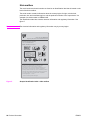
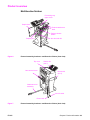
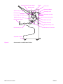

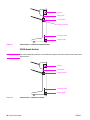


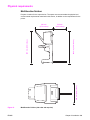
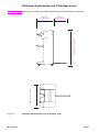
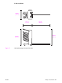


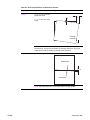


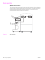
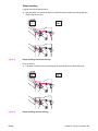
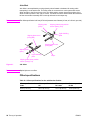


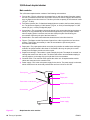
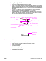


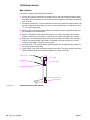
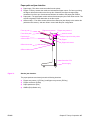
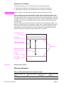
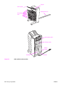
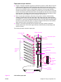

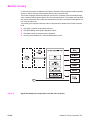


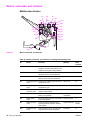


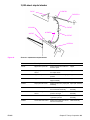
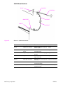
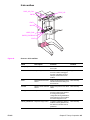


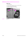

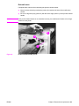
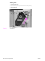


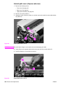
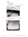


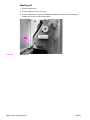
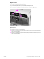
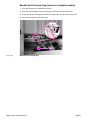
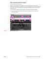

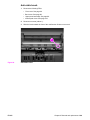

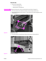

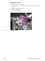

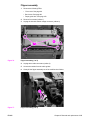
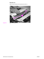
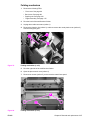
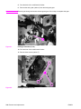
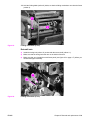
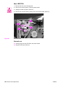
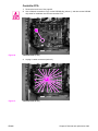
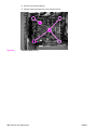
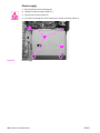
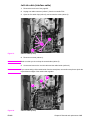
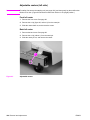

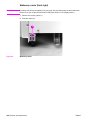

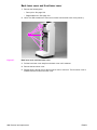


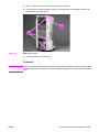
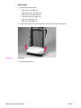
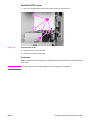


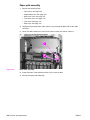
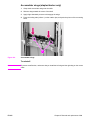
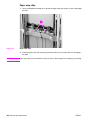

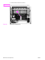
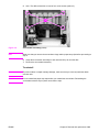

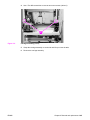
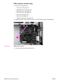
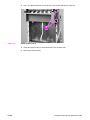
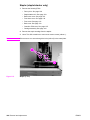
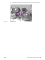
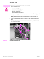

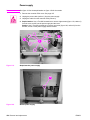
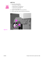

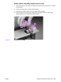
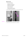
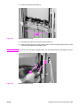
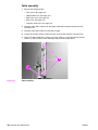
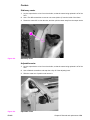

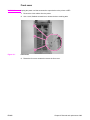
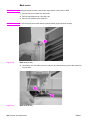
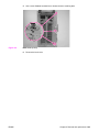


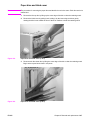

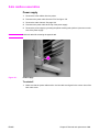


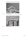
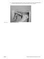
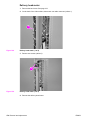
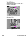


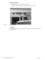
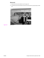

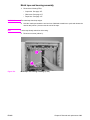

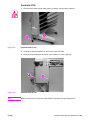
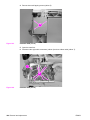
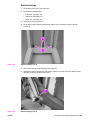


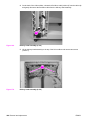


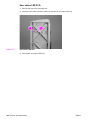
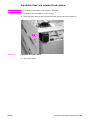
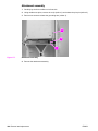

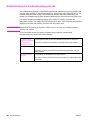

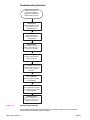


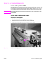

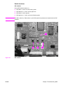
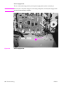

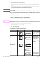


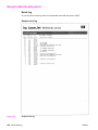
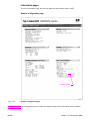


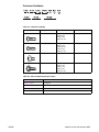
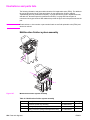

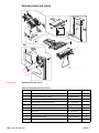

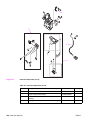

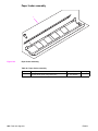

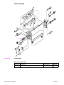
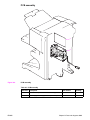

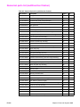

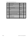
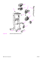
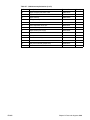
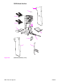
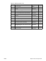


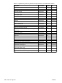
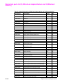


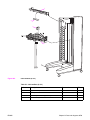
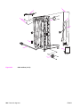

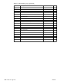


![IL 2.003.01 [Delta MK2]e-pag1.ai](http://vs1.manualzilla.com/store/data/005753338_1-488e124ad81f3853ba4b74f093f13849-150x150.png)