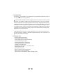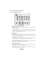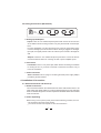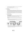
1
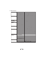
SAFETY RELATED SYMBOLS
External Connection
CAUTION
Always use proper ready-made insulated
mains cabling (power cord). Failure to do
so could result in shock/death or fire. If
in doubt, seek advice, from a registered
electrician.
RISK OF ELECTRIC SHOCK
DO NOT OPEN
This symbol, wherever used, alerts
you to the presence of un-insulated
and dangerous voltages within the
product enclosure. These are voltages
that may be sufficient to constitute the
risk of electric shock or death.
Do not Remove any Covers
Within the product are areas where high
voltages may present. To reduce the risk
of electric shock do not remove any
covers unless the AC mains power cord
is removed.
Covers should be removed by qualified
service personnel only.
No user serviceable parts inside.
This symbol, wherever used, alerts
you to important operating and maintenance instructions. Please read.
Protective Ground Terminal
AC mains (Alternating Current)
Hazardous Live Terminal
Fuse
ON: Denotes the product is turned on.
OFF: Denotes the product is turned off.
To prevent fire and damage to the
product, use only the recommended
fuse type as indicated in this manual.
Do not short-circuit the fuse holder.
Before replacing the fuse, make sure
that the product is OFF and disconnected
from the AC outlet.
WARNING
Describes precautions that should be
observed to prevent the possibility of
death or injury to the user.
CAUTION
Protective Ground
Describes precautions that should be
observed to prevent damage to the
product.
Before turning the product ON, make sure
that it is connected to Ground. This is to
prevent the risk of electric shock.
Never cut internal or external Ground wires.
Likewise, never remove Ground wiring
from the Protective Ground Terminal.
WARNING
Power Supply
Ensure that the mains source voltage (AC
outlet) matches the voltage rating of the
product. Failure to do so could result in
damage to the product and possibly the user.
Unplug the product before electrical storms
occur and when unused for long periods of
time to reduce the risk of electric shock or
fire.
Operating Conditions
Always install in accordance with the
manufacturer's instructions.
To avoid the risk of electric shock and
damage, do not subject this product to
any liquid/rain or moisture. Do not use this
product when in close proximity to water.
1
Do not install this product near any direct
heat source.
Do not block areas of ventilation. Failure
to do so could result in fire.
Keep product away from naked flames.
IMPORTANT SAFETY INSTRUCTIONS
Read these instructions
Follow all instructions
Keep these instructions. Do not discard.
Heed all warnings.
Only use attachments/accessories
specified by the manufacturer.
Power Cord and Plug
Do not tamper with the power cord or plug.
These are designed for your safety.
Do not remove Ground connections!
If the plug does not fit your AC outlet seek
advice from a qualified electrician.
Protect the power cord and plug from any
physical stress to avoid risk of electric shock.
Do not place heavy objects on the power
cord. This could cause electric shock or fire.
Cleaning
When required, either blow off dust from
the product or use a dry cloth.
Do not use any solvents such as Benzol
or Alcohol.
For safety, keep product clean and free
from dust.
Servicing
Refer all servicing to qualified service
personnel only.
Do not perform any servicing other than
those instructions contained within the
User's Manual.
2
Preface
Dear Customer:
Thank you for choosing the LTO TOPVerb 40 bit digital effects module which is the result
of our LTO AUDIO TEAM's endeavours.
For LTO AUDIO TEAM music and audio are much more than a job, they are a passion
and an obsession!
We have, in fact, been designing professional audio products for a number of years in
cooperation with many of the world's major brands.
The LTO line represents unparalleled analogue and digital products made by musicians,
for musicians. With our design centres in Italy, the Netherlands, and the United Kingdom
we provide you with world-class designs, while our software development teams continue
to develop and impressive range of audio specific algorithms.
By purchasing our LTO products you become the most important member of our LTO
AUDIO TEAM. We would like to share with you our passion for what we design and we
invite you to make suggestions, which will aid us in developing future products for you.
We guarantee you our commitment to quality, continual research and development, and
of course the best performance/price ratio.
Our LTO TOPVerb is the result of many hours of listening and tests involving common
people, area experts, musicians and technicians.
The result of this effort is the realization of effects such as reverb, chorus, flanger and delay that are today available in the best guitar amplifiers and studio equipment in the world,
effects that we collected in our small, efficient and easy to use LTO TOPVerb.
We would like to thank all the people that worked with us to make a vision real! Our designers and LTO staff made the LTO TOPVerb 40 bit digital effects module, a very
reliable and high quality product. And thanks to their passion for music and professional
audio it has been possible for us to offer you, our most important team member, our continued support too.
Thank you very much.
LTO AUDIO TEAM
3
Table of Contents
1. Introduction ........................................................................................................... 5
2. Feature List ............................................................................................................ 5
3. Front and Back Panels Description ................................................................. 6
3.1 Control Panel (Front Panel)
a. Program and Variations Selections
b. Analog Levels
c. Digital Saturation LED and Power LED
3.2 Analog Connections (Back Panel)
a. Analog Inputs/Outputs
b. Effects Bypass Pedal Input
c. Power Connector
4. Installation & Connection .................................................................................. 7
4.1 Audio Connections and Power Up
a. Audio Connections
b. Power Up Setting
4.2 Installation
a. Standard Use
b. Application Examples
- Line Instrument
- Mixer
5. Preset Functions Descriptions ....................................................................... 10
5.1 Presets
5.2 Effects Summary Table
6. Technical Specifications .............................................................................................. 19
7. Warranty ..............................................................................................................................
4
21
1. Introduction
Purchasing LTO TOPVerb, you purchased a very powerful effect processor, easy to
use and contained in a very small box.
LTO TOPVerb is divided in 16 effects algorithms and 16 variations for each of these
algorithms. The variations modify the most important parameter of the current algorithm.
The first 8 algorithms are reverb algorithms and have been designed following theory
of different reverberation algorithms, taking care about the density and the body of the
reverberated sound. The second 8 algorithms have been designed following the theory
of modulation effects as chorus, flanger and rotary speakers. Within this second group
of algorithms are included also the delay, tremolo and combined effects as delay/reverb,
flanger/reverb and chorus/reverb.
All the algorithms are based on classical algorithms for the effects generation and environment response modeling, modified and optimized thanks to the experience of
LTO AUDIO TEAM researchers.
2. Feature List
Robust and Compact Design
40 bits Digital Audio Processor
Automatic Bypass Foot Switch Detection
16 Great Sounding Programs
Variation Adjust Knob (16 positions)
Analog Mix (Dry/Wet) Potentiometer
Variable Input/Output Gain
Stereo/Mono Jack Inputs on 1/4" phone jacks
Digital Saturation LED
Up to 9dBu Line Level
Easy to Operate Front Panel Controls
SMT Design for Greater Reliability
Manufactured Under QS9000, VDA6.1 Quality System
5
3. Front and Back Panels Description
3.1 Control Panel (Front Panel)
R
LTO
TOPVerb
TM
40 bit Digital Effects Module
1 HALL1
8 PLATE2
15 CHORUS / REV.
22
~
29
~
36
~
2 HALL2
9 TREMOLO
16 ROTARY
23
~
30
~
37
~
3 HALL3
10 CHORUS
17
~
24
~
31
~
38
~
4 SPRING1
11 FLANGER
18
~
25
~
32
~
39
~
5 SPRING2
12 DELAY
19
~
26
~
33
~
40
~
6 TAPE
13 DELAY / REV.
20
~
27
~
34
~
41
~
7 PLATE1
14 FLANGER / REV.
21
~
28
~
35
~
42
~
0
10
16
1
16
2
15
3
14
5
13
6
12
7
11
0
10
10
INPUT
PEAK
9
2
3
14
4
5
13
6
12
7
11
8
PROGRAM
1
15
4
10
9
8
VARIATIONS
OUTPUT
DRY
PWR
WET
MIX
a. Program and Variations Selections
- Program Select Knob: The Program Select Knob is used to choose the program
you wish to perform.
- Variations Select Knob: Each program on this apparatus has one parameter
which can be adjusted. Depending on the type of program selected, this knob
might alter reverb decay, chorus depth, etc.
b. Analog levels
- Analog Input Level Potentiometer: The input level control sets the main input
Gain, before the signal reaches the input bus. It controls both the Left (Mono)
and Right input levels simultaneously.
- Analog Output Level Potentiometer: The output level control sets the level
of the output signal going to the amplifier or mixer from TOPVerb.
- Dry/Wet Mix Potentiometer: Adjusts the balance between the dry signal coming
into the input and the effects generated by TOPVerb.
c. PEAK LED and Power LED
- PEAK LED: This LED lights up when the input signal is too strong. In case of
the unit being muted, this LED also lights up.
- Power LED: when this unit is connected to mains, this LED will turn red, which
means the unit is in the state of standby.
6
3.2 Analog Connections (Back Panel)
A102
INPUT
OUTPUT
9 VAC~
POWER
FOOT SWITCH
R
L
R
L (MONO)
a. Analog Inputs/Outputs
- Inputs: These are 1/4" unbalanced phone jacks which connect to sources such
as the effects sends of mixing console. They may be used with nominal input
level.
For mono application, use the Left / Mono input. The Left / Mono input jack is
normal to the Right jack. This means that when nothing is plugged into the Right
input jack, the signal present at the Left / Mono input is routed to the Right as
well.
- Outputs: These are 1/4" unbalanced phone jacks which connect to devices
such as the effects returns on a mixing console or power amplifier inputs.
b. Foot switch
- Foot Switch: This is a 1/4" phone jack, which allows connecting a footswitch
for muting the unit. If you want to activate or inactivate the effects, only to
touch the footswtich.
c. Power Connector
- Power connector: This is a plug for connecting the 9VAC power supply adaptor
provided by the manufacturer.
4. Installation & Connection
4.1 Audio Connections and Power Up
a. Audio Connections
The connections between the TOPVerb and the other audio devices have to be
made using high quality cables so to prevent bad performances of the TOPVerb
itself. So it should be good to use low-capacitance shielded cables with a flexible
internal conductor.
b. Power Up Setting
Before turning on the system's power, please use the following procedure, check if:
All connections have been made correctly.
The volume controls of the amplifier or mixer are turned down.
7
Insert the Power plug into the POWER input on the rear panel of the TOPVerb and
plug the power adapter into an AC outlet.
Turn on the power of the amplifier/mixer, and adjust the volume.
4.2. Installation
a. Standard Use
The TOPVerb may be placed almost anywhere: on a table, on top of an amp,
next to a mixing console. If it will be on furniture, check the rubber feet provided
to the bottom of the unit. Make sure to place the TOPVerb's power supply away
from other audio equipment that may induce fields, and away from the signal
wiring. It is possible that TOPVerb may pick up noise fields generated by other
equipment such as large power amplifiers; in this case, move the TOPVerb until
the noise goes away.
b. Application Examples
- LINE INSTRUMENT
When connecting audio cables and/or power cord to mains, make sure that all
devices in your system have their volume controls turned down.
The TOPVerb has two 1/4" unbalanced inputs and two 1/4" unbalanced outputs.
These input/output configuration may provide three different audio connections
options:
MONO. Connect an audio cable to the [LEFT] INPUT of the TOPVerb from a
mono source, and another audio cable from the [LEFT] output of the TOPVerb
to an amplification system or mixer input.
To Amplifier or Mixing Console
From Instrument or Effects Send
Left Input
Left Output
A102
INPUT
OUTPUT
9 VAC~
POWER
FOOT SWITCH
R
L
R
L (MONO)
MONO IN, STEREO OUT. While still using a mono input, you could connect
two audio cables to the [LEFT] and [RIGHT] outputs of the TOPVerb to a stereo
amplification system or two mixer inputs.
8
To Amplifier or Mixing Console
From Instrument or Effects Send
Left Input
Right Output Left Output
A102
INPUT
OUTPUT
9 VAC~
POWER
FOOT SWITCH
R
L (MONO)
R
L
STEREO. Connect two audio cables to the [LEFT] and [RIGHT] INPUTS of
the TOPVerb from a stereo source, and two other audio cables from the [LEFT]
and [ RIGHT] OUTPUTS of the TOPVerb to a stereo amplification system
or two mixer inputs.
To Amplifier or Mixing Console
Right Output
From Instrument or Effects Send
Right Input
Left Output
A102
Left Input
INPUT
OUTPUT
9 VAC~
POWER
FOOT SWITCH
R
L (MONO)
R
L
- MIXER
Interfacing to a Mixing Console
The TOPVerb can accept mono or stereo sends at all system levels. The input
circuitry of the TOPVerb can easily accept professional +8/9dBu levels while
having enough input and output gain to interface with the low signal levels of
home recording systems.
Aux Send
Aux Return
A102
INPUT
OUTPUT
9 VAC~
POWER
MIXING CONSOLE
FOOT SWITCH
R
L
R
L (MONO)
The TOPVerb may be connected to a mixing console in several different ways.
It can be used to with multiple channels at once by using the auxiliary send
and return controls of the mixer. Another way of interfacing is to connect the
TOPVerb directly to the insert send and return of a single channel that is to be
effected. More, TOPVerb could be to connected to a mixer or recording console
9
in-line between the output of the mixing console and the input of a tape deck
or power amplifier. This last setup would effect the entire mix output.
5. Preset Functions Descriptions
5.1 Presets
1). Hall 1
This is a large bright hall program with 54ms predelay, and can be used for almost anything.
2). Hall 2
This is a warmer hall program with 54ms predelay, and adds depth and character
to acoustic instruments.
3). Hall 3
The third program is a medium bright hall with no predelay, and can be used on
rock snares and percussions.
4). Spring1
This program is suitable for organs and will still find them in many guitar amplifiers.
5). Spring2
This program is similar to the previous one, and also be used in organs and
guitar amplifiers.
6). Tape
This program allows you to create more complex patterns that can add a rhythmic quality to the instrument.
7). Plate1
The plate algorithm simulates the "sound" of a classic plate reverb. The plate1
is a classic bright vocal plate.
8). Plate2
A warmer variation of the previous program, sounding very well on acoustic guitar
and strings.
9). Tremolo
This program provides an amplitude modulation of the input signal and is normally
used as "WET" effect without adding direct sound or adding a few percentage
of it, so to avoid the direct sound to cover the amplitude modulation.
10). Chorus
This program tries to recreate the illusion of more than one instrument from a
single instrument sound. Typical modulated effect suitable for vocals, guitar and
keyboards.
10
11). Flanger
Typical flanging effect, particularly effective on guitar and other string instruments.
12). Delay
This program provides a delay of up to 650ms. The delay time can be adjusted
in terms of delay and the decay time depends automatically from the delay time.
This is a useful utility program which can add space to vocals or instruments.
13). Delay + Reverb
The multi-effects program adds a room to the different delay presets. Particularly suitable for the use with vocals.
14). Flanger + Reverb
The multi-effects program is a layered stereo flange and large room reverb. It
works great on guitars, synths and electric pianos.
15). Chorus + Reverb
The multi-effects program is a layered stereo chorus and large room reverb.
Also that one works great on guitars, synths and electric pianos.
16). Rotary
The rotary speaker effect simulates the sound effect achieved by rotating horn
speakers and a bass cylinder. It can be used for organs and guitar amplification.
5.2 Effects Summary Table
TOPVerb PRESET LEST
01. Hall 1
No.
Rev Time Room Size Rev. Type Pre-Delay Hi Damp
1
2
3
4
5
6
7
8
9
10
11
12
13
14
15
16
0.70
0.70
0.70
0.70
1.20
1.20
1.20
1.20
2.10
2.10
2.10
2.10
2.90
2.90
2.90
2.90
8.00
9.03
10.06
11.08
12.11
13.14
14.17
15.19
8.00
9.03
10.06
11.08
12.11
13.14
14.17
15.19
Hall
Hall
Hall
Hall
Hall
Hall
Hall
Hall
Hall
Hall
Hall
Hall
Hall
Hall
Hall
Hall
11
54
54
54
54
54
54
54
54
54
54
54
54
54
54
54
54
-12
-12
-12
-12
-12
-12
-12
-12
-12
-12
-12
-12
-12
-12
-12
-12
Efx
Connect type
100
98
96
94
92
90
88
86
84
82
80
78
76
74
72
70
D(D)
D(D)
D(D)
D(D)
D(D)
D(D)
D(D)
D(D)
D(D)
D(D)
D(D)
D(D)
D(D)
D(D)
D(D)
D(D)
02. Hall 2
No.
Rev Time Room Size Rev. Type Pre-Delay Hi Damp
1
2
3
4
5
6
7
8
9
10
11
12
13
14
15
16
3.6
3.6
3.6
3.6
4.0
4.0
4.0
4.0
4.5
4.5
4.5
4.5
6.1
6.1
6.1
6.1
16.22
17.25
18.28
19.31
20.33
21.36
22.39
23.42
16.22
17.25
18.28
19.31
20.33
21.36
22.39
23.42
Hall
Hall
Hall
Hall
Hall
Hall
Hall
Hall
Hall
Hall
Hall
Hall
Hall
Hall
Hall
Hall
54
54
54
54
54
54
54
54
54
54
54
54
54
54
54
54
-12
-12
-12
-12
-12
-12
-12
-12
-12
-12
-12
-12
-12
-12
-12
-12
03. Hall 3
No.
Rev Time Room Size Rev. Type Pre-Delay Hi Damp
1
2
3
4
5
6
7
8
9
10
11
12
13
14
15
16
0.70
0.70
0.70
0.70
1.20
1.20
1.20
1.20
2.10
2.10
2.10
2.10
2.90
2.90
2.90
2.90
24.44
25.47
26.50
27.53
28.56
29.58
30.61
31.64
32.67
33.69
34.72
35.75
36.78
37.81
40.89
45.00
Hall
Hall
Hall
Hall
Hall
Hall
Hall
Hall
Hall
Hall
Hall
Hall
Hall
Hall
Hall
Hall
12
0
0
0
0
0
0
0
0
0
0
0
0
0
0
0
0
-12
-12
-12
-12
-12
-12
-12
-12
-12
-12
-12
-12
-12
-12
-12
-12
Efx
Connect type
100
98
96
94
92
90
88
86
84
82
80
78
76
74
72
70
D(D)
D(D)
D(D)
D(D)
D(D)
D(D)
D(D)
D(D)
D(D)
D(D)
D(D)
D(D)
D(D)
D(D)
D(D)
D(D)
Efx
Connect type
100
98
96
94
92
90
88
86
84
82
80
78
76
74
72
70
D(D)
D(D)
D(D)
D(D)
D(D)
D(D)
D(D)
D(D)
D(D)
D(D)
D(D)
D(D)
D(D)
D(D)
D(D)
D(D)
04. Spring 1
No.
Rev Time Room Size Rev. Type Pre-Delay Hi Damp
1
2
3
4
5
6
7
8
9
10
11
12
13
14
15
16
0.70
0.70
0.70
0.70
1.20
1.20
1.20
1.20
2.10
2.10
2.10
2.10
2.90
2.90
2.90
2.90
8.00
9.03
10.06
11.08
12.11
13.14
14.17
15.19
16.22
17.25
18.28
19.31
20.33
21.36
22.39
23.42
Spring
Spring
Spring
Spring
Spring
Spring
Spring
Spring
Spring
Spring
Spring
Spring
Spring
Spring
Spring
Spring
3
3
3
3
3
3
3
3
3
3
3
3
3
3
3
3
-0.16
-0.16
-0.16
-0.16
-0.16
-0.16
-0.16
-0.16
-0.16
-0.16
-0.16
-0.16
-0.16
-0.16
-0.16
-0.16
05. Spring 2
No.
Rev Time Room Size Rev. Type Pre-Delay Hi Damp
1
2
3
4
5
6
7
8
9
10
11
12
13
14
15
16
3.6
3.6
3.6
3.6
4.0
4.0
4.0
4.0
4.5
4.5
4.5
4.5
6.1
6.1
6.1
6.1
26.50
27.53
28.56
29.58
30.61
31.64
32.67
33.69
34.72
35.75
36.78
37.81
38.83
39.86
40.89
45.00
Spring
Spring
Spring
Spring
Spring
Spring
Spring
Spring
Spring
Spring
Spring
Spring
Spring
Spring
Spring
Spring
13
9
9
9
9
9
9
9
9
9
9
9
9
9
9
9
9
-12
-12
-12
-12
-12
-12
-12
-12
-12
-12
-12
-12
-12
-12
-12
-12
Efx
Connect type
100
98
96
94
92
90
88
86
84
82
80
78
76
74
72
70
D(D)
D(D)
D(D)
D(D)
D(D)
D(D)
D(D)
D(D)
D(D)
D(D)
D(D)
D(D)
D(D)
D(D)
D(D)
D(D)
Efx
Connect type
100
98
96
94
92
90
88
86
84
82
80
78
76
74
72
70
D(D)
D(D)
D(D)
D(D)
D(D)
D(D)
D(D)
D(D)
D(D)
D(D)
D(D)
D(D)
D(D)
D(D)
D(D)
D(D)
06. Tape
No.
1
2
3
4
5
6
7
8
9
10
11
12
13
14
15
16
Rev Time Room Size Rev. Type Pre-Delay Hi Damp
Efx
Connect type
Tape
Tape
Tape
Tape
Tape
Tape
Tape
Tape
Tape
Tape
Tape
Tape
Tape
Tape
Tape
Tape
100
98
96
94
92
90
88
86
84
82
80
78
76
74
72
70
D(D)
D(D)
D(D)
D(D)
D(D)
D(D)
D(D)
D(D)
D(D)
D(D)
D(D)
D(D)
D(D)
D(D)
D(D)
D(D)
Efx
Connect type
100
98
96
94
92
90
88
86
84
82
80
78
76
74
72
70
D(D)
D(D)
D(D)
D(D)
D(D)
D(D)
D(D)
D(D)
D(D)
D(D)
D(D)
D(D)
D(D)
D(D)
D(D)
D(D)
0.70
0.80
0.90
1.00
1.20
1.50
1.70
1.70
2.10
2.40
2.40
2.90
3.60
4.00
4.50
6.10
8.00
8.00
8.00
8.00
8.00
8.00
8.00
8.00
8.00
8.00
8.00
8.00
8.00
8.00
8.00
8.00
19
19
19
19
19
19
19
19
19
19
19
19
19
19
19
19
-12
-12
-12
-12
-12
-12
-12
-12
-12
-12
-12
-12
-12
-12
-12
-12
07. Plates 1
No.
Rev Time Room Size Rev. Type Pre-Delay Hi Damp
1
2
3
4
5
6
7
8
9
10
11
12
13
14
15
16
0.70
0.70
0.70
0.70
1.20
1.20
1.20
1.20
2.10
2.10
2.10
2.10
2.90
2.90
2.90
2.90
8.00
9.03
10.06
11.08
12.11
13.14
14.17
15.19
16.22
17.25
18.28
19.31
20.33
21.36
22.39
23.42
Plate
Plate
Plate
Plate
Plate
Plate
Plate
Plate
Plate
Plate
Plate
Plate
Plate
Plate
Plate
Plate
14
19
19
19
19
19
19
19
19
19
19
19
19
19
19
19
19
-12
-12
-12
-12
-12
-12
-12
-12
-12
-12
-12
-12
-12
-12
-12
-12
08. Plates 2
No.
Rev Time Room Size Rev. Type Pre-Delay Hi Damp
26.50
27.53
28.56
29.58
30.61
31.64
32.67
33.69
34.72
35.75
36.78
37.81
38.83
39.86
40.89
45.00
1.20
1.20
1.20
1.20
2.10
2.10
2.10
2.10
2.40
2.40
2.40
2.40
2.90
2.90
2.90
2.90
1
2
3
4
5
6
7
8
9
10
11
12
13
14
15
16
09. Tremolo
No. Mod Freq. Amplit Mod Efx
1
2
3
4
5
6
7
8
9
10
11
12
13
14
15
16
0.3
0.6
0.9
1.2
1.5
1.8
2.1
2.4
2.7
3.0
3.3
3.6
3.9
4.2
4.5
5.0
95
95
95
75
75
75
75
75
55
55
55
55
35
35
35
35
100
100
100
100
100
100
100
100
100
100
100
100
100
100
100
100
Plate
Plate
Plate
Plate
Plate
Plate
Plate
Plate
Plate
Plate
Plate
Plate
Plate
Plate
Plate
Plate
-0.16
-0.16
-0.16
-0.16
-0.16
-0.16
-0.16
-0.16
-0.16
-0.16
-0.16
-0.16
-0.16
-0.16
-0.16
-0.16
19
19
19
19
19
19
19
19
19
19
19
19
19
19
19
19
Efx
Connect type
100
98
96
94
92
90
88
86
84
82
80
78
76
74
72
70
D(D)
D(D)
D(D)
D(D)
D(D)
D(D)
D(D)
D(D)
D(D)
D(D)
D(D)
D(D)
D(D)
D(D)
D(D)
D(D)
10. Chorus
Connect type No. Mod Freq. Pitch Depth
C(M)
C(M)
C(M)
C(M)
C(M)
C(M)
C(M)
C(M)
C(M)
C(M)
C(M)
C(M)
C(M)
C(M)
C(M)
C(M)
15
1
2
3
4
5
6
7
8
9
10
11
12
13
14
15
16
0.10
0.21
0.32
0.60
0.76
0.96
1.37
2.16
0.11
0.94
1.61
2.13
1.78
2.50
3.33
3.50
100
100
100
100
100
100
100
100
75
75
75
75
75
75
75
75
Efx
Connect type
100
100
100
100
100
100
100
100
100
100
100
100
100
100
100
100
C(M)
C(M)
C(M)
C(M)
C(M)
C(M)
C(M)
C(M)
C(M)
C(M)
C(M)
C(M)
C(M)
C(M)
C(M)
C(M)
11. Flange
No. Mod Freq. Amplit Mod Feedback L/R Dir Level Efx
1
2
3
4
5
6
7
8
9
10
11
12
13
14
15
16
0.07
0.07
0.07
0.16
0.16
0.16
0.16
0.16
0.22
0.33
0.57
0.76
1.00
1.33
1.42
1.88
100
100
100
100
100
100
100
100
100
100
100
100
100
100
100
100
67
75
82
60
72
82
89
92
82
82
82
82
82
82
82
82
100
100
100
100
100
100
100
100
100
100
100
100
100
100
100
100
40
40
40
40
40
40
40
40
40
40
40
40
40
40
40
40
Connect type
C(M)
C(M)
C(M)
C(M)
C(M)
C(M)
C(M)
C(M)
C(M)
C(M)
C(M)
C(M)
C(M)
C(M)
C(M)
C(M)
12. Delay
No. Delay R/L
1
2
3
4
5
6
7
8
9
10
11
12
13
14
15
16
Feedback L/R
30
40
50
60
70
82
104
204
304
354
400
450
500
550
600
650
13. Delay/Rev
Delay R/L Feedback L/R Rev Time Room Size Hi Damp
No.
1
2
3
4
5
6
7
8
9
10
11
12
13
14
15
16
30
40
50
60
70
82
104
204
304
354
400
450
500
550
600
650
0
0
0
0
0
0
40
40
40
40
40
40
40
40
40
40
0.70
0.80
0.90
1.00
1.20
1.50
1.70
1.70
2.10
2.40
2.40
2.90
3.60
4.00
4.50
6.10
16
8
8
8
8
8
8
8
8
8
8
8
8
8
8
8
8
-12
-12
-12
-12
-12
-12
-12
-12
-12
-12
-12
-12
-12
-12
-12
-12
0
0
0
0
0
0
40
40
40
40
40
40
40
40
40
40
Efx
100
100
100
100
100
100
100
100
100
100
100
100
100
100
100
100
Connect type
C(D)
C(D)
C(D)
C(D)
C(D)
C(D)
C(D)
C(D)
C(D)
C(D)
C(D)
C(D)
C(D)
C(D)
C(D)
C(D)
Efx
Connect type
100
98
96
94
92
90
88
86
84
82
80
78
76
74
72
70
C(D)
C(D)
C(D)
C(D)
C(D)
C(D)
C(D)
C(D)
C(D)
C(D)
C(D)
C(D)
C(D)
C(D)
C(D)
C(D)
14. Flange/Rev
No. Mod Freq. Pitch Depth Feedback L/R Dir Level Rev Time Room Size Hi Damp Connect type Efx
1
2
3
4
5
6
7
8
9
10
11
12
13
14
15
16
0.07
0.07
0.07
0.16
0.16
0.16
0.16
0.16
0.22
0.33
0.57
0.76
1.00
1.33
1.42
1.88
100
100
100
100
100
100
100
100
100
100
100
100
100
100
100
100
15. Chorus/Rev
Delay R/L
No.
1
2
3
4
5
6
7
8
9
10
11
12
13
14
15
16
0.10
0.21
0.32
0.60
0.76
0.96
1.37
2.16
0.11
0.94
1.61
2.13
1.78
2.50
3.33
3.50
67
75
82
60
72
82
89
92
82
82
82
82
82
82
82
82
Feedback (L/R)
100
100
100
100
100
100
100
100
75
75
75
75
75
75
75
75
40
40
40
40
40
40
40
40
40
40
40
40
40
40
40
40
0.70
0.80
0.90
1.00
1.20
1.50
1.70
1.70
2.10
2.40
2.40
2.90
3.60
4.00
4.50
6.10
8
8
8
8
8
8
8
8
8
8
8
8
8
8
8
8
Rev Time Room Size Hi Damp
0.70
0.80
0.90
1.00
1.20
1.50
1.70
1.70
2.10
2.40
2.40
2.90
3.60
4.00
4.50
6.10
17
8
8
8
8
8
8
8
8
8
8
8
8
8
8
8
8
-12
-12
-12
-12
-12
-12
-12
-12
-12
-12
-12
-12
-12
-12
-12
-12
-12
-12
-12
-12
-12
-12
-12
-12
-12
-12
-12
-12
-12
-12
-12
-12
C(M)
C(M)
C(M)
C(M)
C(M)
C(M)
C(M)
C(M)
C(M)
C(M)
C(M)
C(M)
C(M)
C(M)
C(M)
C(M)
100
98
96
94
92
90
88
86
84
82
80
78
76
74
72
70
Efx
Connect type
100
98
96
94
92
90
88
86
84
82
80
78
76
74
72
70
C(M)
C(M)
C(M)
C(M)
C(M)
C(M)
C(M)
C(M)
C(M)
C(M)
C(M)
C(M)
C(M)
C(M)
C(M)
C(M)
16. Rotary
Mod Freq Pitch Depth Feedback Dir Level
No.
1
2
3
4
5
6
7
8
9
10
11
12
13
14
15
16
1
4
1
4
1
4
1
4
3
5
3
5
3
5
3
5
10
20
30
40
50
60
70
80
10
20
30
40
50
60
70
80
40
40
40
40
40
40
40
40
40
40
40
40
40
40
40
40
P.S.
A: 1 input - 2 mono output
B: 2 input - 2 mono output
C: 1 input - 1 stereo output - paralle.efx
D: 1 input - 1 stereo output - series.efx
E: 2 input - 1 stereo output
(M): Modulator
(D): Delay
18
40
40
40
40
40
40
40
40
40
40
40
40
40
40
40
40
Efx
Connect type
100
100
100
100
100
100
100
100
100
100
100
100
100
100
100
100
C(M)
C(M)
C(M)
C(M)
C(M)
C(M)
C(M)
C(M)
C(M)
C(M)
C(M)
C(M)
C(M)
C(M)
C(M)
C(M)
6.2 Specifications
Electrical
Input
Frequency Response:
+0.5 / -1.5 dB from 20Hz to 20 kHz
S/N Ratio (process)
80 dB "A" wtg, 20 Hz-22kHz
S/N Ratio (bypass)
>90 dB "A" wtg, 20 Hz-22kHz
THD+Noise:
<0.008% @ 1kHz (0dBV, bypass)
Number of Channels:
2
Format:
1/4" unbalanced
Maximum Level (bypass):
+9 dBu
Impedance:
>500 Kohms
A/D - D/A
Conversions
A/D converter:
1 bit Sigma-Delta
D/A converter:
1 bit Sigma-Delta
Output
Number of Channels:
2
Format:
1/4" unbalanced
Maximum Level (bypass):
+9 dBu
Output Impedance:
<500 ohms
Controls
IN/OUT levels (ANALOG)
Front Panel
PROGRAM selections (2 knobs)
Power, Signal clip LED
Indicators
Rear Panel
Input (LEFT/MONO, RIGHT) 1/4" 2-conductor (mono)
Output (LEFT, RIGHT)
1/4" 2-conductor (mono)
BYPASS
1/4" 2-conductor (auto-sense pedal type)
for momentary footswitches
9 Volt AC Power Transformer
Power
Processing and Processor Speed:
Memory
12 MIPs (million instructions per second)
Internal DSP resolution:
52 bit MPY accumulator
Main Preset Programs
16
Preset Total Combinations 256
Physical
Internal digital audio memory:
3000 milliseconds
Net Weight:
0.57kg(1.26lb)
Dimension:
19
175(W)
130(D)
(6.89"
5.12"
42(H)mm
1.65")
7. WARRANTY
7.1 Warranty registration card
To obtain Warranty Service, the buyer should first fill out and return the enclosed
Warranty Registration Card within 10 days of the Purchase Date.
All the information presented in this Warranty Registration Card gives the manufacturer a better understanding of the sales status, so as to purport a more effective
and efficient after-sales warranty service.
Please fill out all the information carefully and genuinely, miswriting or absence of
this card will void any of your warranty service.
7.2 Return notice
a. In case of return for any warranty service, please make sure that the product is
well packed in its original shipping carton, and it can protect your unit from any
other extra damage.
b. Please provide a copy of your sales receipt or other proof of purchase with the
returned machine, and give detail information about your return address and
contact telephone number.
c. A brief description of the defect will be appreciated.
d. Please prepay all the costs involved in the return shipping, handling and insurance.
7.3 Terms and conditions
a.
LTO warrants that this product will be free from any defects in materials and/or
workmanship for a period of 1 year from the purchase date if you have completed
the Warranty Registration Card in time.
b. The warranty service is only available to the original consumer, who purchased
this product directly from the retail dealer, and it can not be transferred.
c. During the warranty service, LTO may repair or replace this product at its own
option at no charge to you for parts or for labor in accordance with the right side
of this limited warranty.
d. This warranty does not apply to the damages to this product that occurred as the
following conditions:
Instead of operating in accordance with the user's manual thoroughly, any
abuse or misuse of this product.
Normal tear and wear
The product has been altered or modified in any way .
Damage which may have been caused either directly or indirectly by another
product/force/etc.
Abnormal service or repairing by anyone other than the qualified personnel or
technician. And in such cases, all the expenses will be charged to the buyer.
20
e. In no event shall LTO be liable for any incidental or consequential damages.
Some states do not allow the exclusion or limitation of incidental or consequential
damages, so the above exclusion or limitation may not apply to you.
f. This warranty gives you the specific rights, and these rights are compatible with
the state laws, you may also have other statutory rights that may vary from state
to state.
21