1
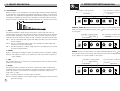
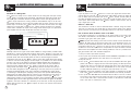
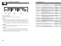
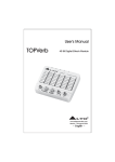
R
LTO
User's Manual
Verb II
TM
40-BIT DIGITAL EFFECTS MODULE
SEIKAKU TECHNICAL GROUP LIMITED
NO. 1, Lane 17, Sec. 2, Han Shi West Road, Taichung 40151, Taiwan
http://www.altoproaudio.com Tel: 886-4-22313737
email: [email protected] Fax: 886-4-22346757
All rights reserved to ALTO. All features and content might be changed
without prior notice. Any photocopy, translation, or reproduction of part of this
manual without written permission is forbidden. Copyright c 2007 Seikaku Group
NF02160-1.4
www.altoproaudio.com
Version 1.0 JUNE 2007
English
9. WARRANTY
1. WARRANTY REGISTRATION CARD
To obtain Warranty Service, the buyer should first fill out and return the enclosed
Warranty Registration Card within 10 days of the Purchase Date.
All the information presented in this Warranty Registration Card gives the
manufacturer a better understanding of the sales status, so as to provide a
more effective and efficient after-sales warranty service. Please fill out all the
information carefully and genuinely, miswriting or absence of this card will void
your warranty service.
2. RETURN NOTICE
2.1 In case of return for any warranty service, please make sure that the
product is well packed in its original shipping carton, and it can protect your
unit from any other extra damage.
2.2 Please provide a copy of your sales receipt or other proof of purchase with
the returned machine, and give detail information about your return address
and contact telephone number.
2.3 A brief description of the defect will be appreciated.
2.4 Please prepay all the costs involved in the return shipping, handling and
insurance.
3. TERMS AND CONDITIONS
3.1 LTO warrants that this product will be free from any defects in materials
and/or workmanship for a period of 1 year from the purchase date if you
have completed the Warranty Registration Card in time.
3.2 The warranty service is only available to the original consumer, who purchased
this product directly from the retail dealer, and it can not be transferred.
3.3 During the warranty service, LTO may repair or replace this product at its
own option at no charge to you for parts or for labor in accordance with the
right side of this limited warranty.
3.4 This warranty does not apply to the damages to this product that occurred
as the following conditions:
Instead of operating in accordance with the user's manual thoroughly, any abuse
or misuse of this product.
Normal tear and wear.
The product has been altered or modified in any way.
Damage which may have been caused either directly or indirectly by another
product / force / etc.
Abnormal service or repairing by anyone other than the qualified personnel or
technician.
And in such cases, all the expenses will be charged to the buyer.
3.5 In no event shall LTO be liable for any incidental or consequential damages.
Some states do not allow the exclusion or limitation of incidental or
consequential damages, so the above exclusion or limitation may not apply to
you.
3.6 This warranty gives you the specific rights, and these rights are compatible
with the state laws, you may also have other statutory rights that may vary
from state to state.
15
IMPORTANT SAFETY INSTRUCTION
CAUTION
RISK OF ELECTRIC SHOCK
DO NOT OPEN
TO REDUCE THE RISK OF ELECTRIC SHOCK
PLEASE DO NOT REMOVE THE COVER OR
THE BACK PANEL OF THIS EQUIPMENT.
THERE ARE NO PARTS NEEDED BY USER
INSIDE THE EQUIPMENT. FOR SERVICE,
PLEASE CONTACT QUALIFIED SERVICE
CENTERS.
WARNING
To reduce the risk of electric shock
and fire, do not expose this equipment
to moisture or rain.
Dispose of this product should
not be placed in municipal waste
and should be separate collection.
11. Move this Equipment only with a cart,
stand, tripod, or bracket,
This symbol, wherever used, alerts you to the
specified by the
presence of un-insulated and dangerous voltages
manufacturer, or
within the product enclosure. These are voltages that
sold with the
may be sufficient to constitute the risk of electric
Equipment. When
shock or death.
a cart is used, use
This symbol, wherever used, alerts you to
caution when
important operating and maintenance instructions.
moving the cart /
Please read.
equipment
Protective Ground Terminal
combination to
AC mains (Alternating Current)
avoid possible
Hazardous Live Terminal
injury from tip-over.
ON: Denotes the product is turned on.
12. Permanent hearing loss may be caused by
OFF: Denotes the product is turned off.
exposure to \ extremely high noise levels.
CAUTION
The US. Government's Occupational Safety
Describes precautions that should be observed to
and Health Administration (OSHA) has
prevent damage to the product.
specified the permissible exposure to noise
1. Read this Manual carefully before operation.
level.
2. Keep this Manual in a safe place.
These are shown in the following chart:
3. Be aware of all warnings reported
with this symbol.
HOURS X DAY SPL EXAMPLE
4. Keep this Equipment away from water and
90 Small gig
8
moisture.
92 train
6
5. Clean it only with dry cloth. Do not use
95 Subway train
4
solvent or other chemicals.
97 High level desktop monitors
3
6. Do not damp or cover any cooling opening.
100 Classic music concert
2
Install the equipment only in accordance with
102
1,5
the Manufacturer's instructions.
105
1
7. Power Cords are designed for your safety. Do
110
0,5
not remove Ground connections! If the plug
0,25 or less 115 Rock concert
does not fit your AC outlet, seek advice from
a qualified electrician. Protect the power
According to OSHA, an exposure to high SPL in
cord and plug from any physical stress to
excess of these limits may result in the loss of
avoid risk of electric shock. Do not place
heat. To avoid the potential damage of heat, it is
heavy objects on the power cord. This could
cause electric shock or fire.
recommended that Personnel exposed to
equipment capable of generating high SPL use
8. Unplug this equipment when unused for long
hearing protection while such equipment is
periods of time or during a storm.
under operation.
9. Refer all service to qualified service personnel
The apparatus shall be connected to a mains
only. Do not perform any servicing other than
those instructions contained within the
socket outlet with a protective earthing
User's Manual.
connection.
10. To prevent fire and damage to the product,
use only the recommended fuse type as
indicated in this manual. Do not short-circuit
the fuse holder. Before replacing the fuse,
make sure that the product is OFF and
disconnected from the AC outlet.
The mains plug or an appliance coupler is used
as the disconnect device, the disconnect device
shall remain readily operable.
IN THIS MANUAL:
1.
2.
3.
4.
5.
6.
7.
8.
9.
INTRODUCTION.............................................................................1
FEATURES.....................................................................................1
CONTROL ELEMENTS....................................................................2
INSTALLATION AND CONNECTION.................................................4
PRESET DESCRIPTION..................................................................9
PRESET LIST..............................................................................12
BLOCK DIAGRAM.......................................................................13
TECHNICAL SPECIFICATIONS........................................................14
WARRANTY.................................................................................15
1. INTRODUCTION
Thank you for your purchasing the Verb II digital multi-effect. It is just one of the
many LTO products that a talented, multinational Team of Audio Engineers and
Musicians have developed with their great passion for music. The verb II has been
created with no economies thinking at the challenges of the digital era. It is made
in roadworthy and durable package for live and recording studio applications. The
Verb II includes 16 Factory Presets including Reverbs, Chorus, Flanger and Delay,
as well as 16 variations of the basic preset for each one of them for a total of
256 powerful and flexible different preset sounds.
Enjoy your Verb II and make sure to read this Manual carefully before operation!
2. FEATURES
Robust and Compact Design
40-bit Digital Audio Processor
16 Great Sounding Programs
Variation adjust knob (16 positions)
256 presets in total
Analog Mix (Dry/Wet) control
User adjustable Input and Output Gain
Stereo/Mono Jack Inputs
LED control for digital overdrive
Easy to operate Front Panel controls
SMT Design for greater reliability
Short Signal Path and no internal cabling to provide superior sound
Manufactured under QS9000, VDA6.1 Quality System
1
8. TECHNICAL SPECIFICATION
Electrical
Frequency Response:
S/N Ratio (process)
S/N Ratio (bypass)
THD+Noise:
Input
Number of Channels:
Format:
Maximum Level (bypass):
Impedance:
A/D - D/A Conversions
A/D converter:
D/A converter:
Output
Number of Channels:
Format:
Maximum Level (bypass):
Output Impedance:
Front Panel
Controls
Indicators
Rear Panel
Input (LEFT/MONO, RIGHT)
Output (LEFT, RIGHT)
BYPASS
Power
Processing and Memory
Processor Speed:
Internal DSP resolution:
Main Preset Programs
Preset Total Combinations
Internal digital audio memory:
Physical
Net Weight:
Dimension:
+0.5 / -1.5 dB from 20 Hz to 20 kHz
80 dB "A" wtg, 20 Hz-22 kHz
>90 dB "A" wtg, 20 Hz-22 kHz
<0.008% @ 1 kHz (0 dBv, bypass)
2
1/4" unbalanced
+9 dBu
>500 kOhms
1 bit Sigma-Delta
1 bit Sigma-Delta
2
1/4" unbalanced
+9 dBu
<500 Ohms
IN/OUT levels (ANALOG)
PROGRAM selections (2 knobs)
Power, Signal clip LED
1/4" 2-conductor (mono)
1/4" 2-conductor (mono)
1/4" 2-conductor (auto-sense pedal type)
for momentary footswitches
9 Volt AC Power Adaptor
12 MIPs (million instructions per second)
52-bit MPY accumulator
16
256
3000 milliseconds
0.76 kg(1.26lb)
197(W) 131(D) 44(H)mm (7.76"
5.12" 1.73")
14
7. BLOCK DIAGRAM
SP
OT
L
IG
3. CONTROL ELEMENTS
HT
Front Panel:
R
LTO
Verb
TM
40 bit Digital Effects Module
Tremolo
Chorus
8
7
Flange
6
Delay
Delay/Rev 5
Flange/Rev 4
Chorus/Rev 3
2
Rotary
Plate 2
Plate 1
Tape
Spring 2
Spring 1
0
10
0
10
0
10
SIGNAL
INPUT
MIX
OUTPUT
2
5
4
3
Hall 3
Hall 2
Hall 1
9
10
11
12
13
1
16
14
15
PWR
VARIATIONS
6
7
1
1 POWER LED
This LED will light up when the AC adaptor is plugged into your
AC outlet.
Verb II and the
2 INPUT
This control adjusts the analog input signal level. It controls both the Left (Mono)
and Right input levels simultaneously.
3 SIGNAL LED
The LED will light up if the input level is too high. In this case you will experience
audible distortion. If the Signal LED lights up, turn the INPUT control down until
the LED does not light up at all. Alternatively you can reduce the output level at
the instrument source.
4 OUTPUT
This control adjusts the analog output signal level going to the amplifier or mixer
from your Verb II.
5 MIX
This control adjusts the balance between the dry signal at the input stage and
the signal processed by your Verb II. If you turn it down completely, you will not
hear and process the signal at all. In center position you will hear the original
(DRY) signal and the processed signal (WET) in equal parts, and if you turn it up
fully, you will only hear the processed (WET) signal.
6 PROGRAMS
With this big selection knob you access one of the built-in 16 Factory Presets. Choose
among a wide range of reverbs, chorus, flanger, delays and combination of them.
7 VARIATIONS
Through this control you can apply 16 different modifications for each of the original
16 Programs selected. See Section 5 "Description of Presets" for further information.
In total you have available 256 different Presets in your Verb II.
13
2
SP
OT
L
IG
3. CONTROL ELEMENTS
6. PRESET LIST
HT
NO.
Rear Panel
9 VAC~
POWER
A102
LEFT
8
11
Description
RIGHT
LEFT(MONO)
HALL1
Simulate a stage space of the sound.
Decay time
Pre-delay
0.7~2.9s
54ms
2
HALL2
Simulate a large acoustic space of the sound.
Decay time
Pre-delay
3.6~6.1s
77ms
3
HALL3
Simulate a medium bright hall with no pre-delay
of the sound.
Decay time
Pre-delay
0.7~2.9s
0ms
4
SPRING1
Suitable for organs and also be used in organs
and guitar amplifiers.
Decay time
Pre-delay
0.7~2.9s
3ms
5
SPRING2
Similar to the previous one, and also be used in
organs and guitar amplifiers.
Decay time
Pre-delay
3.6~6.1s
9ms
6
TAPE
Create more complex patterns that can add a
rhythmic quality to the instrument.
Decay time
Pre-delay
7
PLATE1
Simulate the transducers sound like classic bright
vocal plate.
Decay time
Pre-delay
0.7~6.1s
19ms
0.7~2.9s
19ms
8 POWER CONNECTOR
To Plug-in the AC adaptor included with your
8
PLATE2
Simulate a warmer variation of the previous program, Decay time
sounding very well on acoustic guitar and strings.
Pre-delay
1.2~2.9s
19ms
9
TREMOLO
Provide an amplitude modulation of the input signal
and is used as "WET" effect.
Rate
0.3~5.0Hz
10
CHORUS
Recreate the illusion of more than one instrument
from a single instrument sound.
Rate
0.1~3.5Hz
11
FLANGER
Simulate to play with another person carrying
out same the notes on the same instrument.
Rate
0.07~1.88Hz
12
DELAY
Reproduce the sound input on the output after a
lapse of time.
Decay period
30~650ms
13
REV.+DELAY
Delay with room effect
Decay period
Rev.decay time
30~650ms
0.7~6.1s
14
REV.+FLANGER Stereo flanger and large room reverb
Flanger Rate 0.07~1.88Hz
Rev.decay time
0.7~6.1s
15
REV.+CHORUS
Stereo chorus and large room reverb
Chorus rate
Rev.decay time
16
Rotary
Simulate the sound effect achieved by the
rotating horn speakers and a bass cylinder
RIGHT
9
10
Verb II.
9 INPUT
These 1/4" unbalanced phone jacks connect to sources such as the effects sends of
mixing console. They may be used with a nominal input level up to 9 dBu. For mono
application, use the Left (Mono) input. In this case, the Left (Mono) input jack is in
parallel to the Right jack. This means that when nothing is plugged into the Right input
jack, the signal present at the Left (Mono) input is routed to the Right input as well.
10 OUTPUT
These are 1/4" unbalanced phone jacks to connect your
on a mixing console or power amplifier inputs.
Controllable Parameter
Parameter
Variable range
1
INPUT
OUTPUT
BYPASS
Preset
Verb II to the effects returns
Rate
0.3~3.5Hz
0.7~6.1s
1.0~5.0Hz
11 BYPASS
This is a 1/4" phone jack to connect an optional footswitch. With the footswitch is in
"ON" position, you will hear the Input signal without any digital processing. When the
footswitch is in "OFF" position, you will hear the processed signal with the amount of
DRY/WET proportion you have set from the front panel.
3
12
4.
AND CONNECTION
3. INSTALLATION
CONTROL ELEMENTS
5. PRESET DESCRIPTION
d. ROTARY (SPEAKERS)
4.1 AUDIO CONNECTIONS AND POWER UP
Amp Mod
LPF
Input
HPF
Cyl%
a. Audio Connections
The connections between your Verb II and other audio devices have to be made
using high quality cables to prevent the bad performance. It is advisable to use
low-capacitance shielded cables with a flexible internal conductor. Connect the cables
to your Verb II properly following these tips:
Var Delay Line
LFO Sin
LFO Sin
LFO Sin
LFO Sin
Var Delay Line
Amp Mod
Horn%
The rotary speaker effect simulates the sound effect achieved by rotating horn
speakers and a bass cylinder, as first produced for organs. Leslie anybody? The
sound is altered by the Doppler effect, the directional characteristic of the speakers,
phase effects due to air turbulence, etc. The rotary speaker system is normally used
with organs, but can be used also for guitar amplification.
NOTE: When using the Rotary program, the Mix potentiometer has be turned all
right on "WET" position.
Rotary Parameters Adjust Rate - This control sets the amplitude modulation rate.
5.3 DELAY
Do not bundle audio cables with AC power cords.
Do not place audio cables and your Verb II near sources of electromagnetic
interference such as transformers, monitors, computers, etc.
Do not place cables where they can be stepped on.
Avoid twisting the cable or having it make sharp, right angle turns.
b. Power Up Setting
After making your connections, turn on the system's power using this procedure:
The volume controls of the amplifier or mixer must be turned down.
Insert the Power plug into the POWER input on the rear panel of your
and plug the power adapter into an AC outlet.
Turn on the power of your Verb II, pushing the ON/OFF button on the front panel.
Turn on the power of the amplifier/mixer, and adjust the volume.
Delay effect is a single echo repetition where the repetitions occur after a certain "delay
time" and where the number of repetitions depend on a "decay time", defining the time
necessary to decrease the amplitude of the repetition from the original sound level to
zero. This program provides a delay of up to 1000ms. The delay time can be adjusted
in terms of delay and the decay time depends automatically from the delay time. This is
a useful program which can add space and depth to vocals or instruments.
Inputs
LEFT/CH1
a. Delay+Reverb
b. Flanger+Reverb
c. Chorus+Reverb
Outputs
LEFT/CH1
RIGHT/CH2
Delay Parameters - This control sets the time between the input signal and the first
delay tap and the decay time.
5.4 Combined Effects
Verb II
LEFT/CH1
RIGHT/CH2
LEFT/CH1
RIGHT/CH2
4.2 ANALOG
a. Input Jack Wiring
The [LEFT] INPUT jack of your Verb II is also a mono input. If you only connect a
single mono cable to the [LEFT] INPUT jack, it will be also routed automatically to
the [RIGHT] INPUT. However, if you are using a stereo input signal. the LEFT INPUT
jack will feed only the LEFT INPUT, and the RIGHT INPUT jack will feed only the RIGHT
INPUT.
b. Level Setting
Proper setting of the input and output levels is crucial to get the maximum S/N ratio.
In general, you should set both input and output level controls at3/4 or 75% of full.
11
4
4.
AND CONNECTION
3. INSTALLATION
CONTROL ELEMENTS
This will decrease the possibility of distortion and keep the amount of background
noise to a minimum. If the signal LED of your Verb II starts to light-up ,turn down
the Input level or decrease the output volume of the source (instrument, mixer send,
etc.). If the output level of your Verb II is causing the mixer or amp to distort, turn
down the Output Level of your Verb II.
5. PRESET DESCRIPTION
5.2 MODULATIONS
a. TREMOLO
Amplitude Multiplier
Modulated by Ramp/Sin LFO.
c. Effects Mix Level Adjust
Whether a Preset of your Verb II contains a single effect or two or three effects,
you can adjust the Verb II [MIX] control to obtain a desirable balance between the
original signal and the processed one. Turning [MIX] to the right allow you to hear
more of the processed sound; turning it to the left let you hear more of the source
signal. When hooked up to an instrument setup, such as a guitar amp, the Mix setting
will typically be somewhere in the middle, balancing the processed sound with the
sound of the source instrument. If your Verb II is connected to a mixing console's
Aux Send, the [MIX] control should be set all the way to the right (effects only) so
that the balance can be controlled from the board.
LFO
Tremolo is an amplitude modulation of the signal. It is
useful for adding warmth and life to standing electric
piano or guitar's chords. It is normally used as "WET"
effect without adding direct sound or adding a few
percentage of it, so to avoid the direct sound to cover
the amplitude modulation.
b. CHORUS
Analog Input (Direct)
Input
Effect
Fixed Delay
Var Delay Line
Analog Mix
d. Effects Bypass
At any time you can bypass the sound processing, allowing the direct signal to pass
through your Verb II unchanged. This can be done in two ways: by turning the MIX
knob all the way to the left or by connecting a footswitch to the [BYPASS] jack and
pressing the footswitch. Your Verb II will automatically recognise the right "polarity"
of the pedal.
4.3 INSTALLATION
a. Normal Operation
Your Verb II may be placed almost anywhere: on a table, on top of an amp, next to
a mixing console or inside a standard 19" rack with optional rack mounting kit. If it will
be on a piece of furniture, fix the provided rubber feet to the bottom of the unit. Make
sure to place your Verb II AC adapter away from other audio equipment that may
induce magnetic fields, and away from the signal wiring, it is possible that your Verb II
may pick up noise fields generated by other equipment such as large power amplifiers.
in this case, move your Verb II away until the noise disappears.
b. Application examples
- LINE LEVEL INSTRUMENTS
When connecting audio cables and/or turning power on and off, make sure that all
devices in your system have their volume controls turned down. Your Verb II has two
1/4" unbalanced inputs and two 1/4" unbalanced outputs. The configuration will provide
three different options:
MONO: Connect an audio cable to the [LEFT] INPUT of your Verb II from a mono
source, and another audio cable from the [LEFT] output of your Verb II to an
amplification system or mixer input. Disregard [RIGHT] Input and Output.
5
LFO Sin/Ramp
The Chorus effect tries to recreate the illusion of more than one instrument from a
single instrument sound. Two musicians playing the same instrument never play in
perfect unison (both time and pitch wise). In order to build up the proper illusion using
an electronic device, the original sound is summed with a slightly delayed and detuned
version of itself. Instead of a constant pitch deviation, more natural results come from
a varying pitch deviation (two players never keep equal their relative pitch distance). In
this program we implement the variable delay and the detuning of it is modulated by an
LFO (low frequency oscillator) which causes the detuning to vary. The direct sound and
the detuned one are summed analogically on the outputs.
c. FLANGER
Regeneration%
LFO Sin/Ramp
Input
Delay
Var Delay line
Effect
Analog Mix
LFO Sin/Ramp
In the early days the flanger was a mechanical device: two identical tapes were run
in parallel while an Operator randomly controlled the speed of each unit, making minor
variations up and down the nominal tape speed. Mixing the sound from both tapes,
the signals sometimes aligned in phase, while other times aligned in counter phase,
resulting in a time varying filtering that has been named "flange"'. The structure of the
flanger is then that of the mix of two randomly delayed copies of a signal. Here the
detuning process is same as the one of the chorus, added with a "regeneration" part.
10
4.
AND CONNECTION
3. INSTALLATION
CONTROL ELEMENTS
5. PRESET DESCRIPTION
5.1 THE REVERBS
Reverb in nature, is the combination of a large number of distinct echoes generated
by the reflection of the original sound against obstacles (i.e. walls). In a real acoustic
environment, the amplitude and brightness of these reflections decays over time and
the decaying is depending on the room size, the position of the sound source in acoustic
space, the "nature" of obstacles (shape, material, dimension, etc.) and many other factors.
Left Output
9 VAC~
POWER
INPUT
OUTPUT
LEFT
RIGHT
LEFT(MONO)
RIGHT
MONO IN, STEREO OUT: While still using a mono input, you could connect two audio
cables to the [LEFT] and [RIGHT] outputs of your Verb II to the inputs of an amplifier
or mixing desk.
This preset simulates a large acoustic space (as a concert hall). Hall wants to
simulate large rooms with many reflective surfaces, where sounds can be reflected
and also hided, changing its "colour" over time. This is a classic reverb and can be
used with all sound sources as vocals, drums or acoustic and electric instruments.
To Amplifier or Mixing Console
Right Output
Left Output
Hall 1 - This is a large bright hall program with 54ms pre-delay, and can be used for
almost anything.
Hall 2 - This is a warmer hall program with 77ms pre-delay, and adds depth and
character to acoustic instruments.
Hall 3 - The third program is a medium bright hall with no pre-delay, and can be used
for snares and percussions.
Left Input
BYPASS
A102
a. HALLS
From Instrument or Effects Send
To Amplifier or Mixing Console
9 VAC~
POWER
A102
LEFT
Left Input
INPUT
OUTPUT
BYPASS
From Instrument or Effects Send
RIGHT
LEFT(MONO)
RIGHT
b. SPRING
Spring 1- This program is suitable for organs and will still be found in many guitar amplifiers.
Spring 2- This program is similar to the previous one, and also be used in organs and
guitar amplifiers.
STEREO: Connect two audio cables to the [LEFT] and [RIGHT] INPUTS of the Verb II
from a stereo source, and two other audio cables from the [LEFT] and [RIGHT] OUTPUTS
of your Verb II to a stereo amplifier or mixer inputs.
c. TAPE
To Amplifier or Mixing Console
This program allows you to create more complex patterns that can add a rhythmic
quality to the instrument.
Right Output
From Instrument or Effects Send
Left Input
Right Input
Left Output
d. PLATES
This algorithm wants to simulate the "sound" of a classic plate reverb, obtained using
suspended sheet of metal with transducers at either end. This kind of reverb, commonly
used in the 1970's, it is still useful for its transparent sound and it works well for
vocals, piano, or guitar.
9 VAC~
POWER
A102
INPUT
OUTPUT
BYPASS
LEFT
RIGHT
LEFT(MONO)
RIGHT
Plate 1- The first program is a classic bright vocal plate.
Plate 2- A warmer variation of the previous program, sounding very well on acoustic
guitar and strings.
9
6
4.
AND CONNECTION
3. INSTALLATION
CONTROL ELEMENTS
4.
AND CONNECTION
3. INSTALLATION
CONTROL ELEMENTS
- MIXER
Mono In - Stereo Out
Connection to a Mixing Desk
Your Verb II can accept mono or stereo sends from the mixing desk. The input circuitry
of your Verb II can easily accept professional +8/9 dBu levels while having enough input
and output gain to interface with the low signal levels of home recording systems. Your
Verb II may be connected to a mixing console in several different ways. It can be used
with multiple channels at once by using the auxiliary send and return controls of the mixer.
another way is to connect your Verb II directly to the insert send and return of a single
channel of your mixing desk. In addition, your Verb II could be connected to a recording
console "in-line" between the output of the mixing console and the input of a tape deck or
power amplifier. This last setup would effect the entire mix output.
If you only want to use your Verb II for a mono input signal and connect both of its
outputs back to the mixer, you will need three audio cables. Connect an audio cable
from an effect send to the LEFT input of the Verb II, another 2 audio cables from
the LEFT and RIGHT outputs of the Verb II to a couple of effect returns or other
mixer inputs. With reverb effects your Verb II creates a stereo output, even though
only a single input is used.
Stereo In - Stereo Out
This connection is similar to the one described above. However, using two sends from
the mixer, you need one more audio cable to send a stereo signal to the Verb II's
inputs. The use of a stereo input is especially useful for a true stereo reverb program.
How to Set Aux Send and Return Levels on the Mixer.
Aux Return
In the above connections, it is necessary to set proper levels on the mixer's individual
AUX Sends, AUX Masters, and AUX Return masters (as well as the Verb II's own
controls) to get good, clean, quiet signal.
Aux Send
R
LTO
Verb
TM
40 bit Digital Effects Module
Plate 2
Plate 1
Tape
Spring 2
Spring 1
0
10
0
10
0
10
SIGNAL
INPUT
MIX
OUTPUT
Hall 3
Hall 2
Hall 1
Tremolo
Chorus
8
7
Flange
6
Delay
Delay/Rev 5
Flange/Rev 4
Chorus/Rev 3
2
Rotary
9
10
11
12
13
1
16
14
15
PWR
VARIATIONS
Using Aux Sends and Returns
Generally, there are two types of AUX sends available on mixing consoles: pre-fader sends
(headphone or monitor) and post-fader sends for effects units. Typically, if a mixer has more
than two sends per channel (4, 6 or 8, perhaps), the first two sends are reserved for the
pre-fader sends, while the remaining sends are used to send the signal to external
multi-effects units such as your Verb II. Using a mixer's AUX sends allows each channel
to have its own level control going to the AUX output. It is possible to mix all the channels
we want to be sent to the effects by using the individual channel's AUX send levels on
the mixer. Most consoles also have AUX master controls, which set the overall level of
each AUX output. Sending signal to your Verb II is only half of the process. With a
mixing console, the output of your Verb II must go back to the mixer and turn up in
the mixer before being able to hear it. Depending on the mixer, there are two options for
returning the effected signal to the mixer: connecting to dedicated AUX return inputs,
or connecting to channel inputs. Everything is easy if the mixer provides dedicated inputs
(called returns) for effect devices like your Verb II. If the mixer does not have these, or
all available returns have already been used, it is possible to connect your Verb II to
channel inputs (if there are any remaining). The effect returns generally should only contain
processed signal, and non "DRY" signal mixed with it (since these two signals are blended
together in the mixer). Therefore, it is necessary to set the mixer, so that only processed
("WET") signal is present at your Verb II outputs. To do this, turn the Mix control all the
way to the right.
7
NOTE: Improper level setting is the most common cause of noise and distortion
problems. By having the correct level at every point in the send/return chain, it is
possible to avoid overloading distortion and minimize noise. The most common mistake
using effect units like your Verb II is to have too low the input signal level and to
increase too much the output level to compensate the input and reach the desired
effects level: this amplifies the noise reducing headroom. Here is a procedure that will
give good results with most standard equipment:
1. Set your mixer's input levels correctly.
2. Turn up the mixer channels' AUX Sends and AUX MASTER (if applicable) to a nominal
level (this is usually between "noon" and "3:00" on a rotary knob).
3. Play the source.
4. Turn up the Verb II's [INPUT] level until you see the SIGNAL LED start lighting on
peaks; then reduce it slightly until the LED stops lighting. The ideal input level, to
minimize the noise, is just below the clipping level. But if other instruments will be
added to the mix later, or levels are unpredictable (as in a live show), it's preferable
to leave additional headroom by turning the input level down a bit more.
5. Depending on the input sensitivity of the mixer's channels or AUX Returns, the OUTPUT
knob of the Verb II should be set somewhere between "2:00" and fully clockwise "5:00".
6. Turn up the AUX RETURN level until desired level of effect in the mix is reached.
The control in the chain that may need to be set to a low level is the AUX Return
on the mixer itself. Here is where should increase or decrease the overall effect
level in the mixer to minimize the noise.
8
4.
AND CONNECTION
3. INSTALLATION
CONTROL ELEMENTS
4.
AND CONNECTION
3. INSTALLATION
CONTROL ELEMENTS
- MIXER
Mono In - Stereo Out
Connection to a Mixing Desk
Your Verb II can accept mono or stereo sends from the mixing desk. The input circuitry
of your Verb II can easily accept professional +8/9 dBu levels while having enough input
and output gain to interface with the low signal levels of home recording systems. Your
Verb II may be connected to a mixing console in several different ways. It can be used
with multiple channels at once by using the auxiliary send and return controls of the mixer.
another way is to connect your Verb II directly to the insert send and return of a single
channel of your mixing desk. In addition, your Verb II could be connected to a recording
console "in-line" between the output of the mixing console and the input of a tape deck or
power amplifier. This last setup would effect the entire mix output.
If you only want to use your Verb II for a mono input signal and connect both of its
outputs back to the mixer, you will need three audio cables. Connect an audio cable
from an effect send to the LEFT input of the Verb II, another 2 audio cables from
the LEFT and RIGHT outputs of the Verb II to a couple of effect returns or other
mixer inputs. With reverb effects your Verb II creates a stereo output, even though
only a single input is used.
Stereo In - Stereo Out
This connection is similar to the one described above. However, using two sends from
the mixer, you need one more audio cable to send a stereo signal to the Verb II's
inputs. The use of a stereo input is especially useful for a true stereo reverb program.
How to Set Aux Send and Return Levels on the Mixer.
Aux Return
In the above connections, it is necessary to set proper levels on the mixer's individual
AUX Sends, AUX Masters, and AUX Return masters (as well as the Verb II's own
controls) to get good, clean, quiet signal.
Aux Send
R
LTO
Verb
TM
40 bit Digital Effects Module
Plate 2
Plate 1
Tape
Spring 2
Spring 1
0
10
0
10
0
10
SIGNAL
INPUT
MIX
OUTPUT
Hall 3
Hall 2
Hall 1
Tremolo
Chorus
8
7
Flange
6
Delay
Delay/Rev 5
Flange/Rev 4
Chorus/Rev 3
2
Rotary
9
10
11
12
13
1
16
14
15
PWR
VARIATIONS
Using Aux Sends and Returns
Generally, there are two types of AUX sends available on mixing consoles: pre-fader sends
(headphone or monitor) and post-fader sends for effects units. Typically, if a mixer has more
than two sends per channel (4, 6 or 8, perhaps), the first two sends are reserved for the
pre-fader sends, while the remaining sends are used to send the signal to external
multi-effects units such as your Verb II. Using a mixer's AUX sends allows each channel
to have its own level control going to the AUX output. It is possible to mix all the channels
we want to be sent to the effects by using the individual channel's AUX send levels on
the mixer. Most consoles also have AUX master controls, which set the overall level of
each AUX output. Sending signal to your Verb II is only half of the process. With a
mixing console, the output of your Verb II must go back to the mixer and turn up in
the mixer before being able to hear it. Depending on the mixer, there are two options for
returning the effected signal to the mixer: connecting to dedicated AUX return inputs,
or connecting to channel inputs. Everything is easy if the mixer provides dedicated inputs
(called returns) for effect devices like your Verb II. If the mixer does not have these, or
all available returns have already been used, it is possible to connect your Verb II to
channel inputs (if there are any remaining). The effect returns generally should only contain
processed signal, and non "DRY" signal mixed with it (since these two signals are blended
together in the mixer). Therefore, it is necessary to set the mixer, so that only processed
("WET") signal is present at your Verb II outputs. To do this, turn the Mix control all the
way to the right.
7
NOTE: Improper level setting is the most common cause of noise and distortion
problems. By having the correct level at every point in the send/return chain, it is
possible to avoid overloading distortion and minimize noise. The most common mistake
using effect units like your Verb II is to have too low the input signal level and to
increase too much the output level to compensate the input and reach the desired
effects level: this amplifies the noise reducing headroom. Here is a procedure that will
give good results with most standard equipment:
1. Set your mixer's input levels correctly.
2. Turn up the mixer channels' AUX Sends and AUX MASTER (if applicable) to a nominal
level (this is usually between "noon" and "3:00" on a rotary knob).
3. Play the source.
4. Turn up the Verb II's [INPUT] level until you see the SIGNAL LED start lighting on
peaks; then reduce it slightly until the LED stops lighting. The ideal input level, to
minimize the noise, is just below the clipping level. But if other instruments will be
added to the mix later, or levels are unpredictable (as in a live show), it's preferable
to leave additional headroom by turning the input level down a bit more.
5. Depending on the input sensitivity of the mixer's channels or AUX Returns, the OUTPUT
knob of the Verb II should be set somewhere between "2:00" and fully clockwise "5:00".
6. Turn up the AUX RETURN level until desired level of effect in the mix is reached.
The control in the chain that may need to be set to a low level is the AUX Return
on the mixer itself. Here is where should increase or decrease the overall effect
level in the mixer to minimize the noise.
8
4.
AND CONNECTION
3. INSTALLATION
CONTROL ELEMENTS
5. PRESET DESCRIPTION
5.1 THE REVERBS
Reverb in nature, is the combination of a large number of distinct echoes generated
by the reflection of the original sound against obstacles (i.e. walls). In a real acoustic
environment, the amplitude and brightness of these reflections decays over time and
the decaying is depending on the room size, the position of the sound source in acoustic
space, the "nature" of obstacles (shape, material, dimension, etc.) and many other factors.
Left Output
9 VAC~
POWER
INPUT
OUTPUT
LEFT
RIGHT
LEFT(MONO)
RIGHT
MONO IN, STEREO OUT: While still using a mono input, you could connect two audio
cables to the [LEFT] and [RIGHT] outputs of your Verb II to the inputs of an amplifier
or mixing desk.
This preset simulates a large acoustic space (as a concert hall). Hall wants to
simulate large rooms with many reflective surfaces, where sounds can be reflected
and also hided, changing its "colour" over time. This is a classic reverb and can be
used with all sound sources as vocals, drums or acoustic and electric instruments.
To Amplifier or Mixing Console
Right Output
Left Output
Hall 1 - This is a large bright hall program with 54ms pre-delay, and can be used for
almost anything.
Hall 2 - This is a warmer hall program with 77ms pre-delay, and adds depth and
character to acoustic instruments.
Hall 3 - The third program is a medium bright hall with no pre-delay, and can be used
for snares and percussions.
Left Input
BYPASS
A102
a. HALLS
From Instrument or Effects Send
To Amplifier or Mixing Console
9 VAC~
POWER
A102
LEFT
Left Input
INPUT
OUTPUT
BYPASS
From Instrument or Effects Send
RIGHT
LEFT(MONO)
RIGHT
b. SPRING
Spring 1- This program is suitable for organs and will still be found in many guitar amplifiers.
Spring 2- This program is similar to the previous one, and also be used in organs and
guitar amplifiers.
STEREO: Connect two audio cables to the [LEFT] and [RIGHT] INPUTS of the Verb II
from a stereo source, and two other audio cables from the [LEFT] and [RIGHT] OUTPUTS
of your Verb II to a stereo amplifier or mixer inputs.
c. TAPE
To Amplifier or Mixing Console
This program allows you to create more complex patterns that can add a rhythmic
quality to the instrument.
Right Output
From Instrument or Effects Send
Left Input
Right Input
Left Output
d. PLATES
This algorithm wants to simulate the "sound" of a classic plate reverb, obtained using
suspended sheet of metal with transducers at either end. This kind of reverb, commonly
used in the 1970's, it is still useful for its transparent sound and it works well for
vocals, piano, or guitar.
9 VAC~
POWER
A102
INPUT
OUTPUT
BYPASS
LEFT
RIGHT
LEFT(MONO)
RIGHT
Plate 1- The first program is a classic bright vocal plate.
Plate 2- A warmer variation of the previous program, sounding very well on acoustic
guitar and strings.
9
6
4.
AND CONNECTION
3. INSTALLATION
CONTROL ELEMENTS
This will decrease the possibility of distortion and keep the amount of background
noise to a minimum. If the signal LED of your Verb II starts to light-up ,turn down
the Input level or decrease the output volume of the source (instrument, mixer send,
etc.). If the output level of your Verb II is causing the mixer or amp to distort, turn
down the Output Level of your Verb II.
5. PRESET DESCRIPTION
5.2 MODULATIONS
a. TREMOLO
Amplitude Multiplier
Modulated by Ramp/Sin LFO.
c. Effects Mix Level Adjust
Whether a Preset of your Verb II contains a single effect or two or three effects,
you can adjust the Verb II [MIX] control to obtain a desirable balance between the
original signal and the processed one. Turning [MIX] to the right allow you to hear
more of the processed sound; turning it to the left let you hear more of the source
signal. When hooked up to an instrument setup, such as a guitar amp, the Mix setting
will typically be somewhere in the middle, balancing the processed sound with the
sound of the source instrument. If your Verb II is connected to a mixing console's
Aux Send, the [MIX] control should be set all the way to the right (effects only) so
that the balance can be controlled from the board.
LFO
Tremolo is an amplitude modulation of the signal. It is
useful for adding warmth and life to standing electric
piano or guitar's chords. It is normally used as "WET"
effect without adding direct sound or adding a few
percentage of it, so to avoid the direct sound to cover
the amplitude modulation.
b. CHORUS
Analog Input (Direct)
Input
Effect
Fixed Delay
Var Delay Line
Analog Mix
d. Effects Bypass
At any time you can bypass the sound processing, allowing the direct signal to pass
through your Verb II unchanged. This can be done in two ways: by turning the MIX
knob all the way to the left or by connecting a footswitch to the [BYPASS] jack and
pressing the footswitch. Your Verb II will automatically recognise the right "polarity"
of the pedal.
4.3 INSTALLATION
a. Normal Operation
Your Verb II may be placed almost anywhere: on a table, on top of an amp, next to
a mixing console or inside a standard 19" rack with optional rack mounting kit. If it will
be on a piece of furniture, fix the provided rubber feet to the bottom of the unit. Make
sure to place your Verb II AC adapter away from other audio equipment that may
induce magnetic fields, and away from the signal wiring, it is possible that your Verb II
may pick up noise fields generated by other equipment such as large power amplifiers.
in this case, move your Verb II away until the noise disappears.
b. Application examples
- LINE LEVEL INSTRUMENTS
When connecting audio cables and/or turning power on and off, make sure that all
devices in your system have their volume controls turned down. Your Verb II has two
1/4" unbalanced inputs and two 1/4" unbalanced outputs. The configuration will provide
three different options:
MONO: Connect an audio cable to the [LEFT] INPUT of your Verb II from a mono
source, and another audio cable from the [LEFT] output of your Verb II to an
amplification system or mixer input. Disregard [RIGHT] Input and Output.
5
LFO Sin/Ramp
The Chorus effect tries to recreate the illusion of more than one instrument from a
single instrument sound. Two musicians playing the same instrument never play in
perfect unison (both time and pitch wise). In order to build up the proper illusion using
an electronic device, the original sound is summed with a slightly delayed and detuned
version of itself. Instead of a constant pitch deviation, more natural results come from
a varying pitch deviation (two players never keep equal their relative pitch distance). In
this program we implement the variable delay and the detuning of it is modulated by an
LFO (low frequency oscillator) which causes the detuning to vary. The direct sound and
the detuned one are summed analogically on the outputs.
c. FLANGER
Regeneration%
LFO Sin/Ramp
Input
Delay
Var Delay line
Effect
Analog Mix
LFO Sin/Ramp
In the early days the flanger was a mechanical device: two identical tapes were run
in parallel while an Operator randomly controlled the speed of each unit, making minor
variations up and down the nominal tape speed. Mixing the sound from both tapes,
the signals sometimes aligned in phase, while other times aligned in counter phase,
resulting in a time varying filtering that has been named "flange"'. The structure of the
flanger is then that of the mix of two randomly delayed copies of a signal. Here the
detuning process is same as the one of the chorus, added with a "regeneration" part.
10
4.
AND CONNECTION
3. INSTALLATION
CONTROL ELEMENTS
5. PRESET DESCRIPTION
d. ROTARY (SPEAKERS)
4.1 AUDIO CONNECTIONS AND POWER UP
Amp Mod
LPF
Input
HPF
Cyl%
a. Audio Connections
The connections between your Verb II and other audio devices have to be made
using high quality cables to prevent the bad performance. It is advisable to use
low-capacitance shielded cables with a flexible internal conductor. Connect the cables
to your Verb II properly following these tips:
Var Delay Line
LFO Sin
LFO Sin
LFO Sin
LFO Sin
Var Delay Line
Amp Mod
Horn%
The rotary speaker effect simulates the sound effect achieved by rotating horn
speakers and a bass cylinder, as first produced for organs. Leslie anybody? The
sound is altered by the Doppler effect, the directional characteristic of the speakers,
phase effects due to air turbulence, etc. The rotary speaker system is normally used
with organs, but can be used also for guitar amplification.
NOTE: When using the Rotary program, the Mix potentiometer has be turned all
right on "WET" position.
Rotary Parameters Adjust Rate - This control sets the amplitude modulation rate.
5.3 DELAY
Do not bundle audio cables with AC power cords.
Do not place audio cables and your Verb II near sources of electromagnetic
interference such as transformers, monitors, computers, etc.
Do not place cables where they can be stepped on.
Avoid twisting the cable or having it make sharp, right angle turns.
b. Power Up Setting
After making your connections, turn on the system's power using this procedure:
The volume controls of the amplifier or mixer must be turned down.
Insert the Power plug into the POWER input on the rear panel of your
and plug the power adapter into an AC outlet.
Turn on the power of your Verb II, pushing the ON/OFF button on the front panel.
Turn on the power of the amplifier/mixer, and adjust the volume.
Delay effect is a single echo repetition where the repetitions occur after a certain "delay
time" and where the number of repetitions depend on a "decay time", defining the time
necessary to decrease the amplitude of the repetition from the original sound level to
zero. This program provides a delay of up to 1000ms. The delay time can be adjusted
in terms of delay and the decay time depends automatically from the delay time. This is
a useful program which can add space and depth to vocals or instruments.
Inputs
LEFT/CH1
a. Delay+Reverb
b. Flanger+Reverb
c. Chorus+Reverb
Outputs
LEFT/CH1
RIGHT/CH2
Delay Parameters - This control sets the time between the input signal and the first
delay tap and the decay time.
5.4 Combined Effects
Verb II
LEFT/CH1
RIGHT/CH2
LEFT/CH1
RIGHT/CH2
4.2 ANALOG
a. Input Jack Wiring
The [LEFT] INPUT jack of your Verb II is also a mono input. If you only connect a
single mono cable to the [LEFT] INPUT jack, it will be also routed automatically to
the [RIGHT] INPUT. However, if you are using a stereo input signal. the LEFT INPUT
jack will feed only the LEFT INPUT, and the RIGHT INPUT jack will feed only the RIGHT
INPUT.
b. Level Setting
Proper setting of the input and output levels is crucial to get the maximum S/N ratio.
In general, you should set both input and output level controls at3/4 or 75% of full.
11
4
SP
OT
L
IG
3. CONTROL ELEMENTS
6. PRESET LIST
HT
NO.
Rear Panel
9 VAC~
POWER
A102
LEFT
8
11
Description
RIGHT
LEFT(MONO)
HALL1
Simulate a stage space of the sound.
Decay time
Pre-delay
0.7~2.9s
54ms
2
HALL2
Simulate a large acoustic space of the sound.
Decay time
Pre-delay
3.6~6.1s
77ms
3
HALL3
Simulate a medium bright hall with no pre-delay
of the sound.
Decay time
Pre-delay
0.7~2.9s
0ms
4
SPRING1
Suitable for organs and also be used in organs
and guitar amplifiers.
Decay time
Pre-delay
0.7~2.9s
3ms
5
SPRING2
Similar to the previous one, and also be used in
organs and guitar amplifiers.
Decay time
Pre-delay
3.6~6.1s
9ms
6
TAPE
Create more complex patterns that can add a
rhythmic quality to the instrument.
Decay time
Pre-delay
7
PLATE1
Simulate the transducers sound like classic bright
vocal plate.
Decay time
Pre-delay
0.7~6.1s
19ms
0.7~2.9s
19ms
8 POWER CONNECTOR
To Plug-in the AC adaptor included with your
8
PLATE2
Simulate a warmer variation of the previous program, Decay time
sounding very well on acoustic guitar and strings.
Pre-delay
1.2~2.9s
19ms
9
TREMOLO
Provide an amplitude modulation of the input signal
and is used as "WET" effect.
Rate
0.3~5.0Hz
10
CHORUS
Recreate the illusion of more than one instrument
from a single instrument sound.
Rate
0.1~3.5Hz
11
FLANGER
Simulate to play with another person carrying
out same the notes on the same instrument.
Rate
0.07~1.88Hz
12
DELAY
Reproduce the sound input on the output after a
lapse of time.
Decay period
30~650ms
13
REV.+DELAY
Delay with room effect
Decay period
Rev.decay time
30~650ms
0.7~6.1s
14
REV.+FLANGER Stereo flanger and large room reverb
Flanger Rate 0.07~1.88Hz
Rev.decay time
0.7~6.1s
15
REV.+CHORUS
Stereo chorus and large room reverb
Chorus rate
Rev.decay time
16
Rotary
Simulate the sound effect achieved by the
rotating horn speakers and a bass cylinder
RIGHT
9
10
Verb II.
9 INPUT
These 1/4" unbalanced phone jacks connect to sources such as the effects sends of
mixing console. They may be used with a nominal input level up to 9 dBu. For mono
application, use the Left (Mono) input. In this case, the Left (Mono) input jack is in
parallel to the Right jack. This means that when nothing is plugged into the Right input
jack, the signal present at the Left (Mono) input is routed to the Right input as well.
10 OUTPUT
These are 1/4" unbalanced phone jacks to connect your
on a mixing console or power amplifier inputs.
Controllable Parameter
Parameter
Variable range
1
INPUT
OUTPUT
BYPASS
Preset
Verb II to the effects returns
Rate
0.3~3.5Hz
0.7~6.1s
1.0~5.0Hz
11 BYPASS
This is a 1/4" phone jack to connect an optional footswitch. With the footswitch is in
"ON" position, you will hear the Input signal without any digital processing. When the
footswitch is in "OFF" position, you will hear the processed signal with the amount of
DRY/WET proportion you have set from the front panel.
3
12
7. BLOCK DIAGRAM
SP
OT
L
IG
3. CONTROL ELEMENTS
HT
Front Panel:
R
LTO
Verb
TM
40 bit Digital Effects Module
Tremolo
Chorus
8
7
Flange
6
Delay
Delay/Rev 5
Flange/Rev 4
Chorus/Rev 3
2
Rotary
Plate 2
Plate 1
Tape
Spring 2
Spring 1
0
10
0
10
0
10
SIGNAL
INPUT
MIX
OUTPUT
2
5
4
3
Hall 3
Hall 2
Hall 1
9
10
11
12
13
1
16
14
15
PWR
VARIATIONS
6
7
1
1 POWER LED
This LED will light up when the AC adaptor is plugged into your
AC outlet.
Verb II and the
2 INPUT
This control adjusts the analog input signal level. It controls both the Left (Mono)
and Right input levels simultaneously.
3 SIGNAL LED
The LED will light up if the input level is too high. In this case you will experience
audible distortion. If the Signal LED lights up, turn the INPUT control down until
the LED does not light up at all. Alternatively you can reduce the output level at
the instrument source.
4 OUTPUT
This control adjusts the analog output signal level going to the amplifier or mixer
from your Verb II.
5 MIX
This control adjusts the balance between the dry signal at the input stage and
the signal processed by your Verb II. If you turn it down completely, you will not
hear and process the signal at all. In center position you will hear the original
(DRY) signal and the processed signal (WET) in equal parts, and if you turn it up
fully, you will only hear the processed (WET) signal.
6 PROGRAMS
With this big selection knob you access one of the built-in 16 Factory Presets. Choose
among a wide range of reverbs, chorus, flanger, delays and combination of them.
7 VARIATIONS
Through this control you can apply 16 different modifications for each of the original
16 Programs selected. See Section 5 "Description of Presets" for further information.
In total you have available 256 different Presets in your Verb II.
13
2
IN THIS MANUAL:
1.
2.
3.
4.
5.
6.
7.
8.
9.
INTRODUCTION.............................................................................1
FEATURES.....................................................................................1
CONTROL ELEMENTS....................................................................2
INSTALLATION AND CONNECTION.................................................4
PRESET DESCRIPTION..................................................................9
PRESET LIST..............................................................................12
BLOCK DIAGRAM.......................................................................13
TECHNICAL SPECIFICATIONS........................................................14
WARRANTY.................................................................................15
1. INTRODUCTION
Thank you for your purchasing the Verb II digital multi-effect. It is just one of the
many LTO products that a talented, multinational Team of Audio Engineers and
Musicians have developed with their great passion for music. The verb II has been
created with no economies thinking at the challenges of the digital era. It is made
in roadworthy and durable package for live and recording studio applications. The
Verb II includes 16 Factory Presets including Reverbs, Chorus, Flanger and Delay,
as well as 16 variations of the basic preset for each one of them for a total of
256 powerful and flexible different preset sounds.
Enjoy your Verb II and make sure to read this Manual carefully before operation!
2. FEATURES
Robust and Compact Design
40-bit Digital Audio Processor
16 Great Sounding Programs
Variation adjust knob (16 positions)
256 presets in total
Analog Mix (Dry/Wet) control
User adjustable Input and Output Gain
Stereo/Mono Jack Inputs
LED control for digital overdrive
Easy to operate Front Panel controls
SMT Design for greater reliability
Short Signal Path and no internal cabling to provide superior sound
Manufactured under QS9000, VDA6.1 Quality System
1
8. TECHNICAL SPECIFICATION
Electrical
Frequency Response:
S/N Ratio (process)
S/N Ratio (bypass)
THD+Noise:
Input
Number of Channels:
Format:
Maximum Level (bypass):
Impedance:
A/D - D/A Conversions
A/D converter:
D/A converter:
Output
Number of Channels:
Format:
Maximum Level (bypass):
Output Impedance:
Front Panel
Controls
Indicators
Rear Panel
Input (LEFT/MONO, RIGHT)
Output (LEFT, RIGHT)
BYPASS
Power
Processing and Memory
Processor Speed:
Internal DSP resolution:
Main Preset Programs
Preset Total Combinations
Internal digital audio memory:
Physical
Net Weight:
Dimension:
+0.5 / -1.5 dB from 20 Hz to 20 kHz
80 dB "A" wtg, 20 Hz-22 kHz
>90 dB "A" wtg, 20 Hz-22 kHz
<0.008% @ 1 kHz (0 dBv, bypass)
2
1/4" unbalanced
+9 dBu
>500 kOhms
1 bit Sigma-Delta
1 bit Sigma-Delta
2
1/4" unbalanced
+9 dBu
<500 Ohms
IN/OUT levels (ANALOG)
PROGRAM selections (2 knobs)
Power, Signal clip LED
1/4" 2-conductor (mono)
1/4" 2-conductor (mono)
1/4" 2-conductor (auto-sense pedal type)
for momentary footswitches
9 Volt AC Power Adaptor
12 MIPs (million instructions per second)
52-bit MPY accumulator
16
256
3000 milliseconds
0.76 kg(1.26lb)
197(W) 131(D) 44(H)mm (7.76"
5.12" 1.73")
14
9. WARRANTY
1. WARRANTY REGISTRATION CARD
To obtain Warranty Service, the buyer should first fill out and return the enclosed
Warranty Registration Card within 10 days of the Purchase Date.
All the information presented in this Warranty Registration Card gives the
manufacturer a better understanding of the sales status, so as to provide a
more effective and efficient after-sales warranty service. Please fill out all the
information carefully and genuinely, miswriting or absence of this card will void
your warranty service.
2. RETURN NOTICE
2.1 In case of return for any warranty service, please make sure that the
product is well packed in its original shipping carton, and it can protect your
unit from any other extra damage.
2.2 Please provide a copy of your sales receipt or other proof of purchase with
the returned machine, and give detail information about your return address
and contact telephone number.
2.3 A brief description of the defect will be appreciated.
2.4 Please prepay all the costs involved in the return shipping, handling and
insurance.
3. TERMS AND CONDITIONS
3.1 LTO warrants that this product will be free from any defects in materials
and/or workmanship for a period of 1 year from the purchase date if you
have completed the Warranty Registration Card in time.
3.2 The warranty service is only available to the original consumer, who purchased
this product directly from the retail dealer, and it can not be transferred.
3.3 During the warranty service, LTO may repair or replace this product at its
own option at no charge to you for parts or for labor in accordance with the
right side of this limited warranty.
3.4 This warranty does not apply to the damages to this product that occurred
as the following conditions:
Instead of operating in accordance with the user's manual thoroughly, any abuse
or misuse of this product.
Normal tear and wear.
The product has been altered or modified in any way.
Damage which may have been caused either directly or indirectly by another
product / force / etc.
Abnormal service or repairing by anyone other than the qualified personnel or
technician.
And in such cases, all the expenses will be charged to the buyer.
3.5 In no event shall LTO be liable for any incidental or consequential damages.
Some states do not allow the exclusion or limitation of incidental or
consequential damages, so the above exclusion or limitation may not apply to
you.
3.6 This warranty gives you the specific rights, and these rights are compatible
with the state laws, you may also have other statutory rights that may vary
from state to state.
15
IMPORTANT SAFETY INSTRUCTION
CAUTION
RISK OF ELECTRIC SHOCK
DO NOT OPEN
TO REDUCE THE RISK OF ELECTRIC SHOCK
PLEASE DO NOT REMOVE THE COVER OR
THE BACK PANEL OF THIS EQUIPMENT.
THERE ARE NO PARTS NEEDED BY USER
INSIDE THE EQUIPMENT. FOR SERVICE,
PLEASE CONTACT QUALIFIED SERVICE
CENTERS.
WARNING
To reduce the risk of electric shock
and fire, do not expose this equipment
to moisture or rain.
Dispose of this product should
not be placed in municipal waste
and should be separate collection.
11. Move this Equipment only with a cart,
stand, tripod, or bracket,
This symbol, wherever used, alerts you to the
specified by the
presence of un-insulated and dangerous voltages
manufacturer, or
within the product enclosure. These are voltages that
sold with the
may be sufficient to constitute the risk of electric
Equipment. When
shock or death.
a cart is used, use
This symbol, wherever used, alerts you to
caution when
important operating and maintenance instructions.
moving the cart /
Please read.
equipment
Protective Ground Terminal
combination to
AC mains (Alternating Current)
avoid possible
Hazardous Live Terminal
injury from tip-over.
ON: Denotes the product is turned on.
12. Permanent hearing loss may be caused by
OFF: Denotes the product is turned off.
exposure to \ extremely high noise levels.
CAUTION
The US. Government's Occupational Safety
Describes precautions that should be observed to
and Health Administration (OSHA) has
prevent damage to the product.
specified the permissible exposure to noise
1. Read this Manual carefully before operation.
level.
2. Keep this Manual in a safe place.
These are shown in the following chart:
3. Be aware of all warnings reported
with this symbol.
HOURS X DAY SPL EXAMPLE
4. Keep this Equipment away from water and
90 Small gig
8
moisture.
92 train
6
5. Clean it only with dry cloth. Do not use
95 Subway train
4
solvent or other chemicals.
97 High level desktop monitors
3
6. Do not damp or cover any cooling opening.
100 Classic music concert
2
Install the equipment only in accordance with
102
1,5
the Manufacturer's instructions.
105
1
7. Power Cords are designed for your safety. Do
110
0,5
not remove Ground connections! If the plug
0,25 or less 115 Rock concert
does not fit your AC outlet, seek advice from
a qualified electrician. Protect the power
According to OSHA, an exposure to high SPL in
cord and plug from any physical stress to
excess of these limits may result in the loss of
avoid risk of electric shock. Do not place
heat. To avoid the potential damage of heat, it is
heavy objects on the power cord. This could
cause electric shock or fire.
recommended that Personnel exposed to
equipment capable of generating high SPL use
8. Unplug this equipment when unused for long
hearing protection while such equipment is
periods of time or during a storm.
under operation.
9. Refer all service to qualified service personnel
The apparatus shall be connected to a mains
only. Do not perform any servicing other than
those instructions contained within the
socket outlet with a protective earthing
User's Manual.
connection.
10. To prevent fire and damage to the product,
use only the recommended fuse type as
indicated in this manual. Do not short-circuit
the fuse holder. Before replacing the fuse,
make sure that the product is OFF and
disconnected from the AC outlet.
The mains plug or an appliance coupler is used
as the disconnect device, the disconnect device
shall remain readily operable.