1
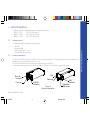
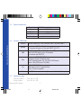
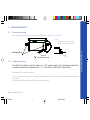
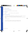
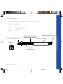
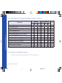
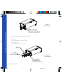
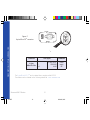
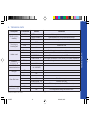
WMO2 Modem Series
GSM 900 / 1800 / 1900
USER MANUAL
GUIDE
1
19/04/99, 9:20
SUMMARY
1. PRODUCT DESCRIPTION
1
Package content
Product presentation
Physical characteristics
Functions - GSM Modes
Temperature range
1
1
2
2
2
2. INSTALLATION/START-UP
3
2.1 Mounting the modem
2.2 Installing the modem
2.3 Electrical characteristics
2.3.1 Switching the GSM modem on/off
2.3.2 Voltage range
2.3.3 Overvoltage/undervoltage
2.3.4 Power supply cable
2.3.5 Input/output electrical characteristics defined for all external connections
2.3.6 Protection/on-board network connection
3
3
4
4
4
4
5
6
6
3. DESCRIPTION OF THE INTERFACES
7
3.1 LED Function
3.2 Connectors
7
7
4. TECHNICAL DATA
11
Wavecom WMO2 Modem
GUIDE
2
19/04/99, 9:20
SUMMARY
1.1
1.2
1.3
1.4
1.5
5. TROUBLESHOOTING:
Specific defaults possibly encountered
5.1 The modem does not answer through the serial link
5.2 The modem always returns «Error» when trying to issue a communication
5.3 The modem always returns «No carrier» when trying to issue a communication
6. NOTES ON SAFETY
6.1
6.2
6.3
6.4
12
13
14
16
General safety
Vehicle safety
Car And Maintenance
Your responsibility
16
17
17
18
19
SUMMARY
7. GENERAL INFORMATIONS
Wavecom WMO2 Modem
GUIDE
12
3
19/04/99, 9:20
1. PRODUCT DESCRIPTION
The Wavecom WMO2 modem exist under three different references:
- WMO2-G900
: GSM 900 MHz version
- WMO2-G1800 : GSM 1800 MHz version
- WMO2-G1900 : GSM 1900 MHz version
Package content
The Wavecom WMO2 modem package comprises:
- 1 Modem
- 2 holding bridles
- 1 Power supply cable + fuse
- 1 User manual (this document)
1.2
Product presentation
The Wavecom WMO2 modem is a terminal for fax and data transmission, short message service mobile originated, short
message service mobile terminated and voice calls.
The connectors binded to the body guarantee output and input connections.
An extractible holder is used to insert the SIM card (Micro-SIM type). A LED indicates the operating mode.
T M
LED
Micro-Fit
connector
Back cap
Front cap
SUB HD
connector
Figure 1
Modem presentation
Wavecom WMO2 Modem
GUIDE
SMA
connector
Extractible
SIM holder
1
4
19/04/99, 9:20
PRODUCT DESCRIPTION
1.1
1.3
Physical characteristics
Dimensions
Overall dimensions
Weight
Volume
Housing
PRODUCT DESCRIPTION
1.4
Functions - GSM Modes
Standard
900 MHz Class 4 (2W) - 1800 / 1900 MHz Class 1 (1W) GSM Phase 2
Interface
Serial interface RS232 V.24/V.28 Autobauding function
AT command set based on V.25ter and GSM 07.05 & 07.07
SMS
Mobile Originated (MO) and Mobile Terminated (MT).
Mode Text & PDU point to point. Cell broadcast.
In accordance with GSM 07.05.
Data
Asynchronous 2400, 4800, 9600 bits/s.
Transparent and Non Transparent mode .
In Non Transparent Mode only: 300, 1200, 1200/75 bauds.
Mode 3.1 KHz (PSTN) and V110 (ISDN).
Fax
2400/4800/7200/9600 bits/s
GSM teleservice 62 in Transparent Mode.
Class 1. Groupe 3 compatible.
Audio
1.5
FR + EFR - Accessories: 1 : Head set (future options) 2 : Car kit (future options)
Temperature range
Operating conditions
Storage conditions
:
:
From -20°C to +55°C
From -25°C to +70°C
Wavecom WMO2 Modem
GUIDE
98x54x25 mm (excluding connectors)
110x54x25 mm
< 140 grams
13.23 cm3
Aluminium profiled
2
5
19/04/99, 9:20
2
INSTALLATION/START-UP
2.1
Mounting the modem
For mounting the modem, bind to the body the holding bridles according to the schema below
:
Figure 2
Modem mounting
2.2
m
m
2
2
mm
Holding bridles
Installing the modem
To install the modem, plug the device on a DC power supply (for automotive application,
connect the device on the permanent « + » and insert the SIM card in the holder).
Make sure that an antenna is connected.
In order to extract or to insert the Micro SIM card, it is necessary to press the SIM holder ejector with a sharp element (a pen
for example).
If this sequence is not respected, the SIM holder could be damaged.
Wavecom WMO2 Modem
GUIDE
3
6
19/04/99, 9:21
INSTALLATION/START-UP
Note:
- To be attached to a plain surface
- Screw head max. height: 2mm
2.3
Electrical characteristics
2.3.1 Switching the GSM modem on/off
The device is permanently powered (when connected to the power supply).
2.3.2 Voltage range
Voltage range
GND
:
:
5 to 32V DC (GSM 900) - 6 to 32V DC (GSM 1800/1900)
0V
2.3.3 Overvoltage/undervoltage
INSTALLATION/START-UP
Correct operation of the Wavecom WMO2 modem in communication mode is not guaranteed if input voltage
fall below 5V (GSM 900) - 6V (GSM 1800/1900). The modem is protected against voltage over 32V.
When input voltages exceed 32V, the supply voltage is disconnected in order to protect the electronic components from an
overvoltage.
TWO CASES ARE POSSIBLE:
- IF THE OVERVOLTAGE IS CONTINUOUS, THE PROTECTION IS GUARANTEED BY THE FUSE.
- IN THE CASE OF TRANSIENT PEAKS, THE MODEM GUARANTEES ITS OWN PROTECTION.
Wavecom WMO2 Modem
GUIDE
4
7
19/04/99, 9:21
2.3.4 Power supply cable
A cable, included in the package shall be used for power supply connection.
The wires are marked as follows:
:
:
:
1 wire
tinned copper 24x0.2 mm
0.75 mm2
Cables stripped over 200 mm,
protected by their own sheath
TM
Connector Molex Micro-Fit 3.0
Stripped wire, tinned over 5 mm
Standard cable sheath
Side view
-
-
++
Figure 3
Power supply cable
Wavecom WMO2 Modem
GUIDE
5
8
19/04/99, 9:21
INSTALLATION/START-UP
Cable
Ame
Section
2.3.5 Input/output electrical characteristics defined for all external connections
GSM 900
Parameters
Min.
Power supply :
- Input supply voltage
- Input supply voltage with Car Kit option
- Input peak supply current
- Input average supply current in communication mode
5
- Input average supply current in idle mode
Serial link : - RS232
Audio (head set) :
- Microphone input current @2V/2KΩ
- Absolute microphone input voltage
- Speaker output current 150Ω/1nF
- Absolute speaker impedance
SIM
INSTALLATION/START-UP
Typ.
GSM 1800/1900
Max.
Min.
32
18
2.5
450
6
Typ.
30
0.5
3 or 5
mA
32
3 or 5
6
9
35
16
32
The modem is protected by a fuse directly binded on the power supply cable.
GUIDE
V
V
A
mA
100
16
19/04/99, 9:21
Unit
32
18
1
200
0.5
100
2.3.6 Protection/on-board network connection
Wavecom WMO2 Modem
Max.
mA
mVp
mA
Ω
V
3. DESCRIPTION OF THE INTERFACES
The modem comprises several interfaces:
- LED function indicating operating status
- External antenna (via SMA)
- Serial and control link (via 15 pins SUB D)
- Power supply (via 4 pins Micro-FitTM)
- SIM card holder
LED Function
3.2
LED off
LED on
LED flashing slowly
LED flashing rapidly
Device switched off - Not ready
Device switched on - Connecting to network
Device switched on - Idle mode
Device switched on - Transmission mode
Connectors
Connector
Function
SMA
RF antenna connector
15 pins SUB D
(high density)
RS232 link
AUDIO link
BOOT
RESET
4 pins Micro-FitTM
Power supply connector
« SIM » connector
SIM card connection
Wavecom WMO2 Modem
GUIDE
7
10
19/04/99, 9:21
DESCRIPTION OF THE INTERFACES
3.1
Figure 4
SMA connector
DESCRIPTION OF THE INTERFACES
SMA connector
(antenna connector)
A SIM card is needed to operate on a GSM network.
To install the card:
- Press the yellow button to eject the holder.
- Insert the SIM card.
- Check that it fits into place correctly.
SIM card
Extractible
SIM card holder
Figure 5
SIM card holder
Yellow button to
eject the holder
(with a sharp element)
Wavecom WMO2 Modem
GUIDE
8
11
19/04/99, 9:21
RS
232
Pins assignment for
15 pins SUB D Connector
Audio
GUIDE
1
10
15
6
11
PIN
EIA
CCIT
Designation
1
DCD
109
Data Carrier Detect
Receive Data (out)
6
RX
104
2
TX
103
Transmit Data
8
DTR
108.2
Data Terminal Ready
9
GND
7
DSR
107
Data Set Ready
Request to send
Signal ground
12
RTS
105
11
CTS
106
Clear to send
13
RI
125
Ring indicator
4
MICROPHONE (+)
5
MICROPHONE (-)
10
SPEAKER (+)
15
SPEAKER (-)
Boot
3
BOOT
Reset
14
RESET
Wavecom WMO2 Modem
5
9
12
19/04/99, 9:22
DESCRIPTION OF THE INTERFACES
Figure 6
15 pins SUB D connector
(high density)
1 2
3 4
DESCRIPTION OF THE INTERFACES
Figure 7
4 pins Micro-FitTM connector
Pins layout
1
2
3-4
V+ BATTERY
GROUND
AUXI
Comments
Power
supply
NC
The 4 pins Micro-Fit 3.0TM can be ordered from a supplier called MOLEX.
The address can be obtained on the following internet site : www.wavecom.com
Wavecom WMO2 Modem
GUIDE
10
13
2
3 4
Connector
4 pins
Micro-Fit 3.0TM
1
19/04/99, 9:22
4. TECHNICAL DATA
Description
AT commands
Module
Comments
AT+CREG ?
CREG=<mode>, 1
Modem synchronized on the network
CREG=<mode>, 2
Synchronization lost, re-synchronization attempt
CREG=<mode>, 0
Network synchronization attempt
Module synchro
checking
RING
Receiving an
incoming call
Answer the call
ATA
OK
ATD1234;
Initiate an
emergency call
Communication established
CME ERROR : 11
PIN code not entered (with +CMEE : 1 mode)
CME ERROR : 3
AOC credit exceeded or a communication is already established
ATD112;
Don't forget the « ; » at the end for « voice » call
OK
Communication loss
NO CARRIER
ATH
Hang up
OK
AT+CPIN=1234
OK
Enter PIN Code
Store the
parameters in E2P
Incorrect PIN Code
+CME ERROR : 3
PIN already entered (with +CMEE : 1 mode)
OK
The configuration settings are stored in E2P
AT&W
Wavecom WMO2 Modem
GUIDE
PIN Code accepted
+CME ERROR : 16
11
14
19/04/99, 9:22
TECHNICAL DATA
Initiate a call
Don't forget the « ; » at the end for « voice » call
OK
5. TROUBLESHOOTING: Specific defaults possibly encountered
5.1
The modem does not answer through the serial link
A) Is the modem correctly powered on?
❏ If not, the correct power supply is 5 to 32V (GSM 900) - 6 to 32V (GSM 1800/1900).
B) Is the serial cable suitable and adjusted in the modem and PC sockets?
❏ A suitable cable must follow pin assignment described on figure 6.
❏ Check in particular, that Rx et Tx are properly connected.
TROUBLESHOOTING
C) Check that your communication program is properly configured:
❏ Modem factory setting for the character framing are:
➫
Data Bits : 8
➫
Parity
: None
➫
Stop Bits : 1
❏
The factory setting for baud rate is autobauding mode.
D) Does any other program interfere with your communication program (conflict on communication port access)?
❏ If yes, close any application likely to interfere (e.g. mouse or printer driver).
Wavecom WMO2 Modem
GUIDE
12
15
19/04/99, 9:22
5.2
The modem always returns «Error» when trying to issue a communication
A) Issue AT+CMEE=1 to have extended error cause and retry
Diagnostic
0
Phone failure
Hint
Call your technical support
3
Operation not allowed
4
Operation not supported
10
SIM not inserted
→ Insert the SIM card in the SIM holder of the modem,
→ If SIM card is inserted, insure that it is properly inserted.
11
SIM PIN required
Enter PIN code
12
SIM PUK required
Enter PUK code (call your network provider if you don’ t know this code)
13
SIM Failure
16
Incorrect password
Check the code you entered
17
SIM PIN2 required
Enter PIN2 code
18
SIM PUK2 required
Enter PUK2 code (call your network provider if you don’ t know this
code)
26
Dial string too long
Check your phone number (max 20 digits)
30
No network service
Check validity of your SIM card. If SIM damaged, call your network
provider
For all other codes, and/or details, see AT commands manual.
B) Additional hints
❏ Is the modem registered on the network?
Does the AT-Command AT + CREG? answers 0,1 (registered) or 0,5 (registered roaming)?
➫
If not, check that the received signal is strong enough to synchronize on the Network (use AT+CSQ).
Wavecom WMO2 Modem
GUIDE
13
16
19/04/99, 9:22
TROUBLESHOOTING
Cause
value
❏
5.3
Is the modem receiving an incoming call or already in communication?
➫
With some software versions, you must release any incoming or active call (with ATH) before being able
to make an outgoing call.
The modem always returns «No carrier» when trying to issue a communication
TROUBLESHOOTING
A) After a failed attempt (“no carrier”), issue AT+CEER to have extended error cause
Cause value
Diagnostic
1
Unallocated phone number
16
Normal call clearing
17
User busy
18
No user responding
19
User alerting, no answer
21
Call rejected
22
Number changed
31
Normal, unspecified
50
Requested facility not subscribed
68
ACM equal or greater than ACMmax
252
Call baring on outgoing calls
253
Call baring on incoming calls
3, 6, 8, 29, 34, 38, 41, 42,
43, 44, 47, 49, 57, 58, 63,
65, 69, 70, 79, 254
Network causes
Hint
Check your subscription (data subscription
available?)
Credit of your pre-paid SIM card expired
See AT commands manual for further details
or call network provider
For all other codes, and/or details, see AT commands manual.
Wavecom WMO2 Modem
GUIDE
14
17
19/04/99, 9:22
B) Additional hints
❏ Is the antenna properly connected?
➫ For GSM 900 : use a 870 to 960 MHz / 50 Ohms antenna.
➫ For GSM 1800 : use a 1710 to 1880 MHz / 50 Ohms antenna.
➫ For GSM 1900 : use a 1850 to 1990 MHz / 50 Ohms antenna.
Is the received signal strong enough?
➫ With the AT-Command AT+CSQ check that the received signal (1st parameter of the response) is strong
enough to be able to establish a call.
AT+CSQ response
(RSSI)
Signal quality
11 to 31
→
Should be sufficient*
0 to 10
and +99
→
Could be insufficient*
* based on general observations.
❏
The modem always returns «No carrier» when trying to issue a voice communication?
➫ Insure the character «semicolon» is present straight after the phone number on the AT-Command
ATD######;
❏
The modem always returns «No carrier» when trying to issue a data communication?
➫ Insure the selected bearer type is supported by the called party.
➫ Then, insure the selected bearer type is supported by the Network.
➫ If no success, try bearer selection type: AT+CBST=0,0,3.
➫ Insure the SIM Card is available for Data/Fax calls.
Wavecom WMO2 Modem
GUIDE
15
18
19/04/99, 9:22
TROUBLESHOOTING
❏
6. NOTES ON SAFETY
6.1
General Safety
It is important to follow any special regulations regarding the use of radio equipment due in particular to the possibility of radio
frequency, RF, interference. Please follow the safety advice given below carefully.
❏ Switch OFF your GSM Modem when in an aircraft. The use of cellular telephones in an aircraft may endanger the
operation of the aircraft, disrupt the cellular network and is illegal. Failure to observe this instruction may lead to suspension
or denial of cellular telephone services to the offender, or legal action or both.
NOTES ON SAFETY
❏ Switch OFF your GSM Modem when at a refueling point.
❏ Switch OFF your GSM Modem in hospitals and any other place where medical equipment may be in use.
❏ Respect restrictions on the use of radio equipment in fuel depots, chemical plants or where blasting operations are in
progress.
❏ There may be a hazard associated with the operation of your GSM Modem close to in adequately protected personal
medical devices such as hearing aids and pacemakers. Consult the manufactures of the medical device to determine if it is
adequately protected.
❏ Operation of your GSM Modem close to other electronic equipment may also cause interference if the equipment is
inadequately protected. Observe any warning signs and manufacturers recommendations.
Wavecom WMO2 Modem
GUIDE
16
19
19/04/99, 9:22
6.2
Vehicle Safety
❏ Do not use your GSM Modem while driving, unless equipped with a correctly installed vehicle kit allowing ‘Hands-Free’
Operation.
❏ Respect national regulations on the use of cellular telephones in vehicles. Road safety always comes first.
❏ If incorrectly installed in a vehicle, the operation of GSM Modem telephone could interfere with the correct functioning of
vehicle electronics. To avoid such problems, ensure that the installation has been performed by a qualified personnel.
Verification of the protection of vehicle electronics should form part of the installation.
6.3
Car And Maintenance
Your GSM Modem is the product of advanced engineering, design and craftsmanship and should be treated with care. The
suggestion below will help you to enjoy this product for many years.
❏ Do not expose the GSM Modem to any extreme environment where the temperature or humidity is high.
❏ Do not attempt to disassemble the GSM Modem. There are no user serviceable parts inside.
❏ Do not expose the GSM Modem to water, rain or spilt beverages, It is not waterproof.
❏ Do not abuse your GSM Modem by dropping, knocking, or violent shaking. Rough handling can damage it.
❏ Do not place the GSM Modem alongside computer discs, credit or travel cards or other magnetic media. The information
contained on discs or cards may be affected by the phone.
Wavecom WMO2 Modem
GUIDE
17
20
19/04/99, 9:22
NOTES ON SAFETY
❏ The use of an alert device to operate a vehicle’s lights or horn on public roads is not permitted.
❏ The use of third party equipment or accessories, not made or authorized by Wavecom may invalidate the warranty of GSM
Modem.
❏ Do contact an authorized Service Center in the unlikely event of a fault.
6.4
Your Responsibility
NOTES ON SAFETY
This GSM Modem is under your responsibility. Please treat it with care respecting all local regulations. It is not a toy therefore
keep it in a safe place at all times and out of the reach of children.
Try to remember your Unlock and PIN codes. Become familiar with and use the security features to block unauthorized use and
theft.
Wavecom WMO2 Modem
GUIDE
18
21
19/04/99, 9:22
GSM reference documents
:
GSM 03.40, GSM 03.45, GSM 04.11,
GSM 04.21, GSM 05.08, GSM 07.01,
GSM 07.02, GSM 07.05, GSM 07.07.
ETSI contact
:
ETSI Secretariat
F-06921 Sophia Antipolis Cedex, France
e-mail : [email protected]
Service
:
The AT commands manual is avalable on Wavecom web site:
http://www.wavecom.com
Disclaimer
Modem and GSM-unit specifications and manuals are subject to change without notice. Wavecom assumes no liability for
damage incurred directly or indirectly from errors, omissions or discrepancies between the modem or GSM-unit and their
manuals.
Trademarks
Some mentioned products are registred trademarks of them respective companies.
Copyright
This manual is copyrighted by Wavecom with all rights reserved. No part of this manual may be reproduced in any form without
the prior written permission of Wavecom.
No patent liability is assumed with respect to the use of the information contained herein.
Wavecom WMO2 Modem
GUIDE
19
22
19/04/99, 9:22
GENERAL INFORMATIONS
7. GENERAL INFORMATIONS
WAVECOM S.A. - 39 rue du Gouverneur Gal. Eboué, F-92130 Issy-les-Moulineaux - France
Tel: +33 1 46 29 08 00 - Fax: +33 1 46 29 08 08
WAVECOM Inc. - 5405 Morehouse Drive, Suite 330 - San Diego, CA 92121 - USA
Tel: +1 619 450 1778 - Fax: +1 619 450 1636
WAVECOM Asia Pacific Ltd. - 2 nd floor, Shui On Center, 6/8 Harbour Road - Hong Kong
Tel: +852 2824 8973 - Fax: +852 2824 8929
GUIDE
23
19/04/99, 9:23