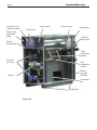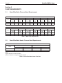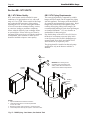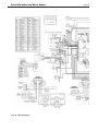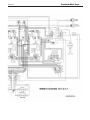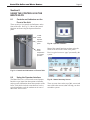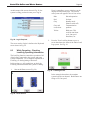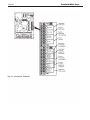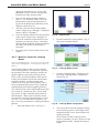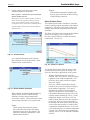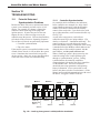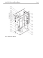
1
Installation and Operation Instructions
Document 1266A
Installation and
Operation Instructions for
Brute Elite LC
Modulating Boiler Water Heater
Model BNTH1000
Model BNTV1000
1,000 MBTU/h
1,000 MBTU/h
Model BNTH1700
Model BNTV1700
1,700 MBTU/h
1,700 MBTU/h
FOR YOUR SAFETY: This product must be installed and serviced by a professional service technician,
qualified in hot water boiler and heater installation and maintenance. Improper installation and/or operation
could create carbon monoxide gas in flue gases which could cause serious injury, property damage, or
death. Improper installation and/or operation will void the warranty.
WARNING
If the information in this manual is not
followed exactly, a fire or explosion may
result causing property damage, personal
injury or loss of life.
Do not store or use gasoline or other
flammable vapors and liquids in the vicinity
of this or any other appliance.
WHAT TO DO IF YOU SMELL GAS
• Do not try to light any appliance.
• Do not touch any electrical switch; do not
use any phone in your building.
• Immediately call your gas supplier from a
nearby phone. Follow the gas supplier’s
instructions.
• If you cannot reach your gas supplier, call
the fire department.
Ne pas entreposer ni utiliser d’essence ni d’autres
vapeurs ou liquides inflammables dans le
voisinage de cet appareil ou de tout autre appareil.
QUE FAIRE SI VOUS SENTEZ UNE ODEUR DE GAZ:
• Ne pas tenter d’allumer d’appareils.
• Ne touchez à aucun interrupteur. Ne pas vous
servir des téléphones dansle bâtiment où vous
vous trouvez.
• Appelez immédiatement votre fournisseur de
gaz depuis un voisin. Suivez les instructions du
fournisseur.
• Si vous ne pouvez rejoindre le fournisseur de
gaz, appelez le sservice des incendies.
L’installation et l’entretien doivent être assurés par
un installateur ou un service d’entretien qualifié ou
par le fournisseur de gaz.
H2360900A
Installation and service must be performed
by a qualified installer, service agency, or gas
supplier.
AVERTISSEMENT
Assurez-vous de bien suivres les instructions
données dans cette notice pour réduire au
minimum le risque d’incendie ou d’explosion ou
pour éviter tout dommage matériel, toute blessure
ou la mort.
238-50567-00B REV 7/14
Bradford White Corp.
Brute Elite Boilers and Water Heaters
Table of Contents
Section 1 - General Information.........................................1
1.1Introduction.......................................................1
1.2
About the Brute Elite Control System...............1
1.3
Safety Notes...................................................... 3
1.4
Model Identification.......................................... 3
1.5Warranty............................................................3
1.6
Unit Overview................................................... 4
1.7Dimensions........................................................ 5
1.8Unpacking......................................................... 5
Section 2 - Locating the Unit..............................................7
2.1
Locating the Unit............................................... 7
2.2
Locating Unit for Correct Vent Distance
from Outside Wall or Roof Termination............ 7
Section 3 - Venting and Combustion Air............................ 8
3.1
Combustion Air.................................................8
3.1.1 Combustion Air From Room.............................8
3.1.2Ducted Combustion Air.....................................9
3.2Venting............................................................ 10
3.2.1Common Venting.............................................10
3.2.2Condensate Drain Trap.................................... 10
3.2.3 Venting Requirements Unique to Canada....... 11
3.3
Locating the Vent and Combustion Air
Terminals.........................................................13
3.3.1 Side Wall Vent Terminal..................................13
3.3.2 Side Wall Combustion Air Terminal............... 14
3.3.3 Vertical Vent Terminal.....................................14
3.3.4Vertical Combustion Air Terminal..................14
3.3.5 Installations in the Commonwealth of
Massachusetts.................................................. 14
3.4
Common Vent Test..........................................15
3.5
Outdoor Installation.........................................15
Section 4 - Gas Supply and Piping...................................16
4.1
Gas Supply and Piping.................................... 16
Section 5 - Pump Requirements........................................ 18
5.1
Brute Elite Boiler Flow and Head
Requirements...................................................18
5.2
Brute Elite Water Heater Flow and Head
Requirements...................................................18
Section 6 – Water Connections.........................................19
Section 6A - NTH Units.................................................... 19
6A.1
NTH System Piping: Hot Supply
Connections..................................................... 19
6A.2
NTH Cold Water Make-Up.............................19
6A.3
NTH Freeze Protection....................................19
6A.4
NTH Suggested Piping Schematics.................20
Section 6B - NTV Units.................................................... 26
6B.1
NTV Water Quality......................................... 26
6B.2
NTV Piping Requirements..............................26
6B.3
NTV Cold Water Make-Up.............................27
6B.4
NTV Freeze Protection....................................27
6B.5
NTV Suggested Piping Schematics................. 27
6B.6
NTV Suggested Pumps...................................28
Section 7 - Electrical Connections.................................... 29
7.1
Main Power.....................................................29
7.2
Pump Connections...........................................29
7.3
24 VAC Transformer with Integral
Circuit Breaker................................................ 31
7.4
Signal Connections..........................................31
7.5
Optional Field Connections............................. 31
7.6
Ladder and Wiring Diagrams..........................31
Section 8 –Using the Controls
on the Brute Elite........................................... 36
8.1
Controls and Indicators on the Front
of the Unit........................................................ 36
8.2
Using the Operator Interface........................... 36
8.3
While Operating – Checking Lead/Lag
Operating Information..................................... 38
8.4
Checking Lead/Lag Master.............................39
8.5
While Operating - Checking Individual
Parameters.......................................................39
8.6
Checking Individual Details............................40
8.7
Configuring Parameters on Individual
Controllers....................................................... 40
8.8
Verification Process for Safety-Related
Parameters.......................................................42
i
Section 9 – Setup and Configuration................................ 44
9.1
Review of Lead/Lag Control System..............44
9.1.1 About Lead/Lag Operation.............................. 44
9.1.2 Lead/Lag Modulation Cycle............................45
9.1.3 NTH Lead/Lag with Indirect
Domestic Hot Water........................................ 46
9.2
Connection Terminals...................................... 46
9.3
Brute Elite System Configurations.................. 48
9.4
Installation Jobs...............................................55
A
Note for Systems Using Common
Venting............................................................ 55
B
Naming the Controllers................................... 55
C
Make One Control the Lead/Lag
Master.............................................................. 56
D
Disable the Lead/Lag Master Function
on the Lead/Lag Slaves................................... 57
E
Set up the Modbus Control Addressing...........58
F
Set the Flap Valve IDs.....................................59
G
Disconnect Unused Operator
Interfaces.........................................................63
H
Connect the Modbus Wiring...........................63
I
Set the Parameters Used by the
Lead/Lag System............................................. 64
About the “Time of Day” Function.................68
J
Install the System Sensor and Adjust
the Setpoint......................................................68
K
Set the Lead/Lag Outdoor Reset and
Warm Weather Shutdown................................ 68
About “Outdoor Reset”...................................69
L
Building Automation or Multiple Boiler
Control Thermostat Demand..........................70
M
Building Automation or Multiple Boiler
4-20mA Setpoint Control............................... 70
N
Building Automation or Multiple Boiler
4-20mA Modulation Control...........................71
O
Combustion Setup Procedure..........................71
P
Setting the Date and Time on the
System Display................................................ 76
9.5
Setup for Domestic Hot Water on a
Lead/Lag System............................................. 77
Setup Type 1.................................................... 77
Setup Type 2.................................................... 78
Setup Type 3.................................................... 79
9.6
Gateway Connections to a
Building Automation System..........................80
9.7
Setup for High Altitude Operation NT 1700 Only.................................................. 80
9.8
Installer Parameters......................................... 81
Bradford White Corp.
Section 10 - Operating Instructions.................................. 88
10.1
Filling the Boiler System.................................88
10.2
Initial Operation.............................................. 89
10.2.1 Initial Burner Operation.................................. 89
10.2.2 Combustion Setup Procedure..........................89
10.3
Shutting Down the Brute Elite........................ 89
10.4
Restarting the Brute Elite................................ 89
Section 11 – Maintenance.................................................90
11.1
System Maintenance.......................................90
11.2
Maintenance Notes..........................................90
11.2.1Burner.............................................................. 90
11.2.2 Modulating Gas Valve/ Venturi.......................90
11.2.3Controllers....................................................... 91
11.2.4 Ignitor Assembly............................................. 91
11.2.5 Flame Sensor................................................... 91
11.2.6 Transformer with Integral
Circuit Breaker................................................ 91
11.2.7Blower............................................................. 92
11.2.8 Heat Exchanger Coils...................................... 92
11.2.9 Gas Pressure Switches (optional).................... 92
11.2.10 Natural/Propane Gas Conversion..................93
Section 12 – Troubleshooting........................................... 94
12.1
Potential Setup and Synchronization
Problems.......................................................... 94
12.1.1 Controller Synchronization............................. 94
12.1.2 Flap Valve Status Checks................................95
12.2
About Lockouts, Holds, and Alerts.................95
12.2.1 Responding to a Lockout, Hold,
or Alert............................................................. 95
12.2.2 Viewing the Lockout and Alert
Histories.......................................................... 96
12.3
Troubleshooting Table..................................... 98
12.4
Diagnostic Tests and Input/Output
Indicators....................................................... 113
12.5
Lead/Lag Slave Diagnostics.......................... 114
12.6Statistics........................................................ 114
12.7Analysis......................................................... 114
12.8
Control Snapshot........................................... 115
12.9
Operating Sequence....................................... 115
Section 13 – Replacement Parts...................................... 118
13.1
General Information...................................... 118
13.2
Parts List........................................................ 118
13.3
Parts Illustrations...........................................124
ii
Page 1
Brute Elite Boilers and Water Heaters
Section 1
General Information
1.1Introduction
This manual includes information which will help
you to install, operate, and maintain the Brute Elite
1000 and 1700 systems. Please read this manual
completely before proceeding with the installation.
If you have any questions regarding this equipment,
please consult the Bradford White factory, or a local
factory representative. Many operating problems are
caused by improper installation.
Touch Screen Display
(behind the plastic cover
which slides downward)
WARNING
Brute Elite’s must be installed in accordance
with the procedures detailed in this manual,
or the Bradford White Corporation warranty
will be voided. The installation must conform
to the requirements of the local jurisdiction
having authority, and, in the United States,
to the latest edition of the National Fuel Gas
Code, ANSI Z223.1/NFPA54. In Canada, the
installation must conform to the latest edition
of CSA B149.1 Natural Gas and Propane Gas
Installation Code, and/or local codes. Where
required by the authority having jurisdiction, the
installation of Brute Elite boilers must conform to
the Standard for Controls and Safety Devices for
Automatically Fired Boilers, ANSI/ASME CSD-1.
Any modifications to the boiler, its gas controls,
or wiring may void the warranty. If field conditions
require modifications, consult the factory
representative before initiating such modifications.
Power switch
Pressure and
temperature
gauge
Page 2
Bradford White Corp.
1.2About the Brute Elite Control
System
This unit includes an advanced control system
which can perform many functions. This is part of
the reason why the Brute Elite 1000 or 1700 can
deliver such outstanding performance. There are
several “branches” in the control software, and many
different display screens. For clarity, throughout
this manual we have made a special effort to show
you how to reach each of the important setup and
operating functions. We have done this in two ways:
•
In many cases, we have shown you the actual
screen display you will see while performing a
function.
•
Sometimes, instead of showing the screens, we
have just listed the series of choices you should
make in order to reach the section you want.
The arrangement of the control software is actually
quite logical, and after you have worked with it a bit,
you will not have any problems “finding your way
around.” We just want to give you some help with
the first part of the process, when you are “getting
used to” the control system.
Later in this manual, we will detail information on
the setup and operating procedures. There are a
couple of concepts you will need to understand right
from the start.
Each boiler has two controllers and two
•
burners, as shown in Fig. 1. A single Operator
Interface is used to communicate with both
controllers.
Press here for
system setup
Press here to
see current
Lead/ Lag
performance
Boiler 1
Operator
interface
Primary
controller
Primary
burner
Gas
valve
Secondary
controller
Addr
2
Lead Lag
Master and
Slave 1
Slave 2
Secondary
burner
Control Arrangement in a Single-Boiler
Installation
Each controller and burner work together. Each
boiler includes two of these controller/burner
combinations.
Notice the different terms we are using here.
The term boiler refers to the whole unit – the
complete Brute Elite 1000 or 1700. Each
boiler includes two separate controller/burner
Boiler 2
Boiler 3
Boiler 4
Operator
interface
Addr
1
Gas
valve
Press here
for Lead/ Lag
setup
pairs.
•
Brute Elite 1000 and 1700 units are always set
up for “Lead/Lag” operation. The term “Lead/
Lag” means that, as the heating load increases,
the control system brings additional burners on
automatically.
On a multiple-boiler installation, each of the
individual boilers is still set up as shown in Fig.
1 above. The controller/burner pairs on all of the
boilers are arranged in a “daisy chain.” Up to four
boilers, with up to eight controller/burner pairs, can
be connected in this way. See Fig. 2.
Boiler 1
Fig. 1 –
Press here
for individual
controller/
burner pairs
Addr
3
Addr
4
Slave 3
Slave 4
Addr
5
Addr
6
Slave 5
Slave 6
Addr
7
Addr
8
Slave 7
Slave 8
Fig. 2 –Lead/Lag Arrangement in a MultipleBoiler Installation
In a multiple-boiler installation, just one of the
operator interfaces is active. It can communicate
with all of the controller/burner pairs in the system,
so it displays information from all of the burners. A
single system sensor provides the control input for
the system.
Actually, even a Brute Elite 1000 or 1700 unit set
up as a single boiler still uses Lead/Lag operation.
If the heating load becomes too great for the first
burner, the control system automatically starts the
Page 3
Brute Elite Boilers and Water Heaters
second burner.
To work with this control system, you will need
to understand the difference between two kinds of
control functions:
•
Some of the functions control all of the
controller/burner pairs, working together as
part of the Lead/Lag system. As an example,
the setpoint for a whole multiple-boiler system
is set by a single value: “Central Heat Lead/
Lag Setpoint.” By changing this one value,
you change the setpoint used by the whole
system. The action of all of the controller/
burner pairs will refer back to that single value.
On the Operator Interface, from the Home
screen you can reach all of the Lead/Lag
functions by pressing the View Lead Lag
button. See Fig. 3.
•
Other functions apply only to each separate
controller/burner pair. As an example, each
controller/burner has a name, and this can be
changed.
The Home screen on the Operator Interface
will show icons for each of the controller/
burner pairs connected to the system. To
reach one of the functions for an individual
controller/burner, press the icon for that
controller/burner. On the following screen,
press the Configure button. This will take
you to all of the configuration options for that
individual controller/burner.
Fig. 3 –
Going to Lead/Lag and Individual
Functions
Note – For individual functions, if you want to make
a change on all of the controller/burner pairs in the
system, you will have to go to each controller/burner
separately and repeat the change for each of them.
If there are eight controller/burners in the system,
and you want to make the same change on all of
them, go to each of the eight controller/burner pairs
separately.
As we go through the explanations in this manual,
we will point out whether a control function affects
the whole Lead/Lag system, or just an individual
controller/burner pair.
This has been just a quick introduction, but this
manual includes two longer sections that will help
you to work with the control system:
•
Section 8 – “Using the Controls on the Brute
Elite.”
This is an introduction to the Operator
Interface. It explains how to “get along” with
the interface: how to move through the various
screens, enter and change values, and so on.
•
Section 9 – “Setup and Configuration”
The first part of this section includes a more
complete explanation of the Lead/Lag system.
The rest of the section includes detailed setup
instructions.
If you are not familiar with the control system, the
installation and setup process will go much more
smoothly if you read through these three sections
before beginning work.
1.3
Safety Notes
WARNING
Fire or Explosion Hazard
Improper configuration can cause fuel buildup and
explosion. Improper user operation may result in
property loss, severe physical injury, or death.
Any changes to safety-related configuration
parameters must only be done by experienced and/or
licensed burner/boiler operators and mechanics.
If any odor of gas is detected, or if the gas burner
does not appear to be functioning in a normal
manner, close the main gas shutoff valve. Do not
shut off the power switch. Contact your heating
contractor, gas company, or factory representative.
The Brute Elite is protected against overpressurization. A pressure relief valve is included
with each Brute Elite.
The inlet gas pressure to the appliance must not
exceed 13” W.C. (3.2 kPa).
All installations must be made in accordance with
1) American National Standard Z223.1/NFPA54Latest Edition “National Fuel Gas Code” or 2) CSA
B149.1 “Natural Gas and Propane Installation Code”
Page 4
and with the requirement of the local utility or other
authorities having jurisdiction. Such applicable
requirements take precedence over the general
instructions contained herein.
1.4
Model Identification
Consult the rating plate on the unit. The following
information describes the model number structure.
(1-3) Model Series Designation
B N T = Brute Elite
(4) Usage
H = Hydronic
V = Volume Water
(5-8) Size
1 0 0 0 = 1,000,000 BTU/hr input
1 7 0 0 = 1,700,000 BTU/hr input
(9) Fuel
N = Natural Gas
P = LP Gas
(10) Options Code
J = CSD1 Version
X = Standard Unit
(11) Pump Options
X = No pump (configuration available for all sizes)
(12) Revision
1 = First version
WARNING
Carbon Monoxide Hazard
Improper adjustment of the burners may lead to poor
combustion quality, increasing the amount of carbon
monoxide produced. Excessive carbon monoxide
levels may lead to personal injury or death.
WARNING
Electrical Shock Hazard
Electrical shock can cause severe injury, death or
property damage. Disconnect the power supply
before beginning installation or changing the
wiring to prevent electrical shock or damage to the
equipment. It may be necessary to turn off more than
one power supply disconnect.
All electrical wiring is to be done in accordance with
local codes, or in the absence of local codes, with:
1) The National Electrical Code ANSI/NFPA No.
70 - latest Edition, or 2) CSA STD. C22.1 “Canadian
Electrical Code - Part 1.” This appliance must be
electrically grounded in accordance with these
codes.
Bradford White Corp.
1.5
Unit Overview
See Figure 4.
1.6Warranty
Bradford White appliances are covered by a
limited warranty.
All warranty claims must be made to an authorized
Bradford White wholesale rep / distributor. To find
information about the wholesalers in your area,
please go to www.bradfordwhite.com. and
click on ‘Wholesalers’.
Claims must include the serial number and model
(this information can be found on the rating plate),
installation date, and name of the installer. Shipping
costs are not included in the warranty coverage.
Some accessory items may be shipped in separate
packages. Verify receipt of all packages listed on
the packing slip. Inspect everything for damage
immediately upon delivery, and advise the carrier of
any shortages or damage. Any such claims should be
filed with the carrier. The carrier, not the shipper,
is responsible for shortages and damage to the
shipment whether visible or concealed.
Model Nomenclature
1
2
3
4
B
N
N
6
7
8
9
10
11
T
SERIES
B
5
T
12
1
USAGE
H -HYDRONIC
V -VOLUME
WATER
SIZE
MBTU/h
1 0 0 0
1 7 0 0
FUEL
OPTIONS CODE
N -NATURAL
J - CSD1
P - PROPANE
X -STANDARD
PUMP OPTIONS
X - NO PUMP
REVISION
1 - FIRST
Page 5
Brute Elite Boilers and Water Heaters
1.6
Unit Overview
Protective Cover
(slides downward)
Touch Screen
Display
Power switch
Ducted air inlet
Electrical box
Pressure and
temperature
gauge
PRV and
flow switch
Blower 1
(under bezel)
Automatic
gas valves
Outlet
temperature
sensors
Manual
gas valve
Inlet
temperature
sensors
Blower 2
Condensate
trap
Leveling feet
Model 1000
Page 6
Protective Cover
(slides downward)
Pressure and
temperature
gauge
Power switch
Bradford White Corp.
Ducted air inlet
Touch Screen
Electrical box
PRV and
flow switch
Blower 1
(behind bezel)
Outlet
temperature
sensors
Automatic
gas valves
Inlet
temperature
sensors
Manual
gas valve
(on back)
Blower 2
Condensate
trap
Leveling feet
Model 1700
Page 7
Brute Elite Boilers and Water Heaters
Fig. 5 - Dimensions - BNT 1000
1.7Dimensions
The dimensions are shown in Fig. 5 and
Fig. 6.
1.8Unpacking
The Brute Elite is shipped in a single crate. The
standard outdoor/system sensor kit is packed inside
the same crate.
1. Remove all packing and tie-down materials.
2. Check that the outdoor/system sensor kit is
included.
DANGER
• Water temperature over 125°F (52°C) can cause
severe burns instantly or death from scalds.
• Children, disabled and elderly are at highest risk of
being scalded.
• See instruction manual before
setting temperature at
heating appliance.
• Feel water before
bathing or showering.
• If this appliance is used
to produce water that
could scald if too hot,
such as domestic hot water
use, adjust the outlet
control (limit) or use temperature limiting valves
to obtain a maximum water temperature of 125°F
(52°C).
Page 8
Fig. 6 - Dimensions - BNT 1700
Bradford White Corp.
Page 9
Brute Elite Boilers and Water Heaters
Section 2
Locating the UNIT
2.1Locating the Unit
The Brute Elite may be installed indoors or
outdoors. The unit may only be installed outdoors
in a location which will never experience freezing
temperatures. Choose a location for the unit which
allows clearances on all sides for maintenance and
inspection. See Table 1. Always install the unit on a
firm, level surface. Level the unit using the leveling
feet.
The unit should not be located in an area where
leakage of any connections will result in damage to
the area adjacent to the appliance, or to lower floors
of the structure.
When this type of location is not available, install
a suitable drain pan, adequately drained, under the
appliance.
The appliance is design-certified by CSAInternational for installation on combustible flooring;
in basements; in closets, utility rooms or alcoves.
Brute Elite boilers must never be installed on
carpeting. The location for the appliance should
be chosen with regard to the vent pipe lengths and
external plumbing.
The unit shall be installed such that the gas ignition
system components are protected from water (dripping,
spraying, rain, etc.) during operation and service
(circulator replacement, control replacement, etc.).
When vented vertically, the Brute Elite must be
located as close as practical to the vertical section
of the vent. If the vent terminal and/or combustion
air terminal terminate through a wall, and there is
potential for snow accumulation in the local area,
both terminals should be installed at an appropriate
level above grade or the maximum expected snow
line.
The dimensions and requirements that are shown in
Table 1 should be met when choosing the locations
for the appliance.
2.2Locating Unit for Correct Vent
Distance from Outside Wall or
Roof Termination
The forced draft combustion air blower in the
appliance has sufficient power to vent properly when
the guidelines in Table 2 are followed.
Note - When located on the same wall, the Brute
Elite combustion air intake terminal must be installed
a minimum of 12” below the exhaust terminal. There
must also be a minimum horizontal distance from
intake to the exhaust terminal of 36.”
Appliance
SUGGESTED SERVICE Access Clearance
Surfaceinches
cm
Front
24
60.9
Left Side
12
30.5
Right Side
18
45.7
Back
24
60.9
Top
24
60.9
Appliance
REQUIRED Clearance TO COMBUSTIBLES
Surfaceinches
cm
Front
2
5.1
Left Side
0
0
Right Side
0
0
Back
0
0
Top
8
20.3
Vent
12.6
Table 1 - Clearances
INTAKE / EXHAUST
Standard
Max Equiv.
SizeVentft.
m
10006”100
17008”
30
10030
Installations in the U.S. require exhaust vent pipe that is PVC or
CPVC complying with ANSI/ASTM D1785 F441, polypropylene
complying with ULC-S636, or stainless steel complying with
UL1738. Installations in Canada require exhaust vent pipe that is
certified to ULC S636.
Intake (air) pipe must be PVC or CPVC that complies with ANSI/
ASTM D1785 F441, ABS that complies with ANSI/ASTM D1527,
stainless steel, or galvanized material.
Closet and alcove installations do not allow the use of PVC under
any circumstances
To calculate max equivalent length, measure the linear feet of the
pipe, and add 5 feet (1.5 m) for each elbow used.
Table 2 - Vent / Air Pipe Sizes
For the concentric vent terminal kit (optional), follow
the installation instructions included with the kit.
Page 10
Bradford White Corp.
Section 3
Venting and Combustion Air
3.1
Combustion Air
Brute Elite boilers and water heaters must have
provisions for combustion and ventilation air in
accordance with the applicable requirements for
Combustion Air Supply and Ventilation in the
National Fuel Gas Code, ANSI Z223 1; or in Canada,
the Natural Gas and Propane Installation Code, CSA
B149.1. All applicable provisions of local building
codes must also be adhered to.
A Brute Elite can take combustion air from the
space in which it is installed, or the combustion
air can be ducted directly to the unit. Ventilation
air must be provided in either case.
3.1.1 Combustion Air From Room
In the United States, the most common requirements
specify that the space shall communicate with the
outdoors in accordance with Method 1 or 2. (See the
following descriptions.) Where ducts are used, they
PVC
shall be of the same cross-sectional area as the free
area of the openings to which they connect.
Method 1: Two permanent openings, one
commencing within 12” (300 mm) of the top and
one commencing within 12” (300 mm) of the
bottom, of the enclosure shall be provided. The
openings shall communicate directly, or by ducts,
with the outdoors or spaces that freely communicate
with the outdoors. When directly communicating
with the outdoors, or when communicating to the
outdoors through vertical ducts, each opening shall
have a minimum free area of 1 square inch per
4000 Btu/hr (550 square mm/kW) of total input
rating of all equipment in the enclosure. When
communicating to the outdoors through horizontal
ducts, each opening shall have a minimum free
area of not less than 1 square inch per 2000 Btu/
hr (1100 square mm/kW) of total input rating of all
equipment in the enclosure.
CPVC
Stainless Steel
Polypropylene
Model
Ducted Air
Exhaust
Ducted Air
Exhaust
Ducted Air
Exhaust
Ducted Air
Exhaust
1,000
CA008100
CA008300
CA008100
CA008300
CA008200
D2004500
CA008500
CS008500
1,700
CA010700
CA010900
CA010700
CA010900
CA011000
CA011100
CA011000
CA011100
Table 3a - Horizontal Terminations for Indoor Use
PVC
CPVC
Stainless Steel
Polypropylene
Model
Ducted Air
Exhaust
Ducted Air
Exhaust
Ducted Air
Exhaust
Ducted Air
Exhaust
1,000
CA008400
CA008300
CA008400
CA008300
CA008500
CA008500
CA008500
CA008500
1,700
CA010800
CA010900
CA010700
CA010900
CA011300
CA011200
CA011200
CA011200
Table 3b - Vertical Terminations for Indoor Use
Model
Ducted Air
Exhaust
1,000
CA008700
CA008900
1,700
CA010400
CA011500
Table 3c - Outdoor Terminations
Material
United States
ABS
ANSI/ASTM D1527
PVC, sch. 40
ANSI/ASTM D1785 or D2665
CPVC, sch. 40
ANSI/ASTM F441
Single wall galv. steel
26 gauge
Polypropylene
ULC-S636 Class 2C
Canada
The air pipe material must be chosen based upon
the intended application of the boiler, and must
be installed according to the vent manufacturer’s
installation instructions.
Table 4 - Required Combustion Air Pipe Material
Page 11
Brute Elite Boilers and Water Heaters
Method 2: One permanent opening, commencing
within 12” (300 mm) of the top of the enclosure,
shall be permitted. The opening shall directly
communicate with the outdoors or shall
communicate through a vertical or horizontal duct
to the outdoors or spaces that directly communicate
with the outdoors and shall have a minimum free
area of 1 square inch per 3000 Btu/hr (734 square
mm/kW) of the total input rating of all equipment
located in the enclosure. This opening must not be
less than the sum of the areas of all vent connectors
in the confined space.
Other methods of introducing combustion and
ventilation air are acceptable, providing they
conform to the requirements in the applicable codes
listed above.
In Canada, consult local building and safety codes
or, in absence of such requirements, follow CAN/
CSA B149.
3.1.2 Ducted Combustion Air
The combustion air can be taken through the wall, or
through the roof. When taken from the wall, it must
be taken from out-of-doors by means of the Bradford
White horizontal wall terminal, shown in Table 3a.
See Table 2 to select the appropriate diameter air
pipe. When taken from the roof, a field-supplied
rain cap or an elbow arrangement must be used to
prevent entry of rain water. (See Fig. 7).
Use ABS, PVC, CPVC, polypropylene, stainless
steel, or galvanized pipe for the combustion air
intake. (See Table 4.) The intake must be sized per
Table 2. Route the intake to the boiler as directly
as possible. Seal all joints. Provide adequate
hangers. The unit must not support the weight of the
combustion air intake pipe. The maximum linear
pipe length allowed is 100 feet (39 m). Subtract 5
allowable linear ft. (1.5 m) for every elbow used.
When using polypropylene or stainless steel
materials in horizontal duct configurations, a single
elbow must be installed on the end of the air inlet
to act as an outdoor terminal. In vertical duct
applications, two elbows must be installed on the
end of the inlet to act as a vent terminal. In both
installation types, Bradford White part number
CA008500 (for Model 1,000) or CA011300 (for
Model 1,700) can then be installed into the elbow
to prevent foreign objects from entering the air inlet
system. The elbow(s) required to complete the vent
terminal is not included.
The connection for the intake air pipe is on the back
panel.
In addition to air needed for combustion, air shall
also be supplied for ventilation, including air
required for comfort and proper working conditions
for personnel. Refer to the applicable codes.
*
*
*
*
* In Canada, refer to CAN/CSA B199.1
*
Fig. 7 - Combustion Air and Vent Through Roof
Installation Standards
Material
United States
Stainless steel
UL 1738
PVC*, sch 40
ANSI/ASTM D178
CPVC, sch 40
ANSI/ASTM F441
Polypropylene
UL-S636 Class 2C
* PVC cannot be used for the first 12 inches of vent material
Table 5 - Required Exhaust Vent Material
Canada
Venting must be ULC-S636 certified for use as
venting material. The venting material class must
be chosen based upon the intended application
of the boiler, and must be installed according to
the maximum flue gas temperature and the vent
manufacturer’s instructions.
*
Page 12
3.2Venting
(90°C) or higher. When installing polypropylene
vent systems, please, refer to the vent supplier’s
installation instructions for proper installation
techniques.
When using PVC/CPVC for the vent material, the
first 12 inches or 305 mm (for Model 1000) or 36”
or 915 mm (for Model 1700) of the vent must be
connected to the CPVC section included with the
Brute Elite. The CPVC vent section included with
the Brute Elite may be broken by CPVC fittings if
necessary, but never reduced in total length. See
Table 2 to select the appropriate vent pipe diameter.
When using polypropylene, all vent material must be
from the same manufacturer and UL-S636 rated.
All installations must be done following the vent
supplier’s recommended installation techniques. If
these are not available, refer to the Bradford White
recommendations for the material used.
The vent pipe must pitch upward, toward the
vent terminal, not less than 1/4” per foot, so that
condensate will run back to the Brute Elite to drain.
Route the vent pipe to the heater as directly as
possible. Seal all joints. Provide adequate hangers
as required in the venting system manufacturer’s
Installation Instructions. Horizontal portions of the
venting system must be supported to prevent sagging
and may not have any low sections that could trap
condensate. The unit must not support the weight of
the vent pipe. Please see Table 2 for proper diameter
vs. length allowed.
WARNING
Selection of improper vent materials for installations
that are installed in closets, or will be operated
in high ambient temperature levels, may lead to
property damage, personal injury, or death.
WARNING
A 12” or 305 mm section (for Model 1000) or 36” or
915 mm section (for Model 1700) of CPVC must be
connected directly to the boiler before a PVC vent
system can be used. Connecting PVC directly to the
boiler’s flue collar may cause vent failure, leading to
property damage, personal injury, or death.
WARNING
Failure to use the appropriate vent material,
installation techniques, or glues and sealants could
lead to vent failure causing property damage,
personal injury or death.
WARNING
All venting must be installed according to this
manual and any other applicable local codes,
including but not limited to, ANSI Z223.1/NFPA 54,
CSA B149.1, CSAB149.2 and ULC-S636. Failure to
follow this manual and applicable codes may lead to
property damage, severe injury, or death.
The flue temperature of the Brute Elite changes
dramatically with changes in operating water
temperature. Therefore, it is necessary to assess
the application of the boiler to determine the
required certified vent class. If the Brute Elite
is installed in an application where the ambient
temperature is elevated, and/or installed in
a closet/alcove, CPVC, polypropylene, or
stainless steel material is required. If the system
temperatures are unknown at the time of
installation, class IIC or higher venting material
is recommended.
The Brute Elite is a Category IV appliance and may
be installed with PVC, CPVC that complies with
ANSI/ASTM D1785 F441, or polypropylene that
complies with ULC-S636 Class 2C, or a stainless
steel venting system that complies with the UL
1738 Standard. (See Table 5.) The unit’s vent can
terminate through the roof, or through an outside
wall.
The use of polypropylene vent material has
been accepted by CSA for use with exhaust and
combustion. The polypropylene vent manufacturer
shall have ULCS636 Class 2C approval or higher
with a recognized listing agency for all components
used in the venting system. All components used
must be from the same manufacturer and designed
for use with exhaust temperatures of 195°F
Bradford White Corp.
3.2.1 Common Venting
A single vent that is shared by multiple Brute
Elite’s must be engineered by a competent venting
specialist, and could involve the selection of
draft inducing equipment, hardware and controls
to properly balance flue gas pressures. Do not
common vent Brute Elite’s unless the vent
system meets this requirement. Brute Elite’s are
never permitted to share a vent with Category I
appliances.
3.2.3
Venting Requirements Unique to
Canada
Brute Elite boilers and water heaters are Vent
Category IV appliances. Per the requirements of
CAN/CSA-B149.1, only BH vent systems can be
connected to these units and such vent systems,
either ULC S636 certified stainless steel or other
ULC S636 certified BH vent (eg. plastics) must
be installed per the vent manufacturer’s certified
installation instructions.
It is the responsibility of the appropriately licensed
technician installing this Brute Elite to use ULC
Page 13
Brute Elite Boilers and Water Heaters
S636 certified vent material consistent with the
requirements as described in the Venting and
Combustion Air section.
Class I venting systems are suitable for gas-fired
appliances producing flue gas temperature of more
than 135°C, but not more than 245°C.
Class II venting systems are suitable for gas-fired
appliances producing flue gas temperatures of 135°C
or less.
Class II venting systems are further classified into
four temperature ratings as follows:
A
Up to and including 65°C
B
Up to and including 90°C
C
Up to and including 110°C, and
D
Up to and including 135°C
Flue Gas Sampling Port It is also the responsibility of the installer to ensure
that a flue gas sampling port is installed in the vent
system. This flue gas sampling port must be installed
near the flue connection of the Brute Elite: within
2 feet of the flue connection. There is no flue gas
sampling port internal to the Brute Elite, so one
must be installed in the vent system external to the
Brute Elite. A flue gas sampling port available as a
component of the ULC S636 certified vent system is
preferred. However, if one is not available with the
certified vent system, Bradford White suggests using
a tee with the branch connection sized to allow for
insertion of a flue gas analyzer probe. The branch
connection must be resealable with a cap or other
means to ensure the vent system remains sealed.
(See Fig. 8.)
Consideration must be given to the placement and
orientation of the flue gas sampling port to ensure
that condensate is free to flow back into the Brute
Elite and not collect anywhere in the vent system including in the flue gas sampling port.
Exhaust Vent Terminal An exhaust vent terminal must be installed. If an
exhaust vent terminal is not available with the
certified vent system, Bradford White suggests
the use of a coupler fitting from the certified vent
system into which the vent terminal screen can be
installed. Be sure to install and terminate both vent
Fig. 8 - Test Port
and combustion air pipes per the instructions in this
section.
3.3Locating the Vent and Combustion
Air Terminals
3.3.1 Side Wall Vent Terminal
The appropriate Bradford White side wall vent
terminal must be used. The terminal must be located
in accordance with ANSI Z223.1/NFPA 54 and
applicable local codes. In Canada, the installation
must be in accordance with CSA B149.1 or .2 and
local applicable codes.
Consider the following when installing the terminal:
1. Figure 9 shows the requirements for
mechanical vent terminal clearances for the
U.S. and Canada.
2. Vent terminals for condensing appliances or
appliances with condensing vents are not
permitted to terminate above a public walkway,
or over an area where condensate or vapor
could create a nuisance or hazard.
3. Locate the vent terminal so that vent gases
cannot be drawn into air conditioning system
inlets.
4. Locate the vent terminal so that vent gases
cannot enter the building through doors,
windows, gravity inlets or other openings.
Whenever possible, avoid locations under
windows or near doors.
5. Locate the vent terminal so that it cannot
be blocked by snow. The installer may
Page 14
Bradford White Corp.
U.S. Installations (see note 1)
Canadian Installations (see note 2)
A= Clearance above grade, veranda, porch, deck, or balcony
12 inches (30 cm)
See note 6
12 inches (30 cm)
See note 6
B= Clearance to window or door that may be opened
Direct vent only: 12 inches (30 cm); Other than Direct vent: 4 ft (1.2m) below or to
side of opening; 1 ft (30 cm) above opening
36 inches (91 cm)
C= Clearance to permanently closed window
See note 4
See note 5
D=
Vertical clearance to ventilated soffit located
above the terminal within a horizontal See note 4
distance of 2 feet (61 cm) from the center
line of the terminal
See note 5
E= Clearance to unventilated soffit
See note 4
See note 5
F= Clearance to outside corner
See note 4
See note 5
G= Clearance to inside corner
See note 4
See note 5
H= Clearance to each side of center line
extended above meter/regulator assembly See note 4
3 feet (91 cm) within a height 15 feet
above the meter/regulator assembly
I=
3 feet (91 cm)
Clearance to service regulator vent outlet
See note 4
J= Clearance to nonmechanical air supply
inlet to building or the combustion air inlet
to any other appliance
Direct vent only: 36” (91cm)
Other than Direct vent: 4 ft (1.2m) below
36 inches (91 cm)
or to side of opening; 1 ft (30 cm) above opening
K= Clearance to a mechanical air supply inlet
3 feet (91 cm) above if within 10 feet (3 m)
horizontally
6 feet (1.83 m)
L= Clearance above paved sidewalk or paved Vent termination not allowed in this location
driveway located on public property
for category IV appliances.
7 ft (2.1 m)
See note 5
M= Clearance under veranda, porch, deck, See note 4
or balcony
12 inches (30 cm)
See note 5
Notes:
1. In accordance with the current ANSI Z223.1 / NFPA 54 National Fuel Gas Code.
2. In accordance with the current CAN/CSA-B149 Installation Codes.
3. Permitted only if veranda, porch, deck, or balcony is fully open on a minimum of two sides beneath the floor.
4. For clearances not specified in ANSI Z223.1 / NFPA 54, clearance is in accordance with local installation codes and the
requirements of the gas supplier.
5. For clearances not specified in CAN/CSA-B149, clearance is in accordance with local installation codes and the requirements of the
gas supplier.
6. IMPORTANT: All terminals must be placed so that they remain a minimum 12” above expected snow line. Local codes may have
more specific requirements, and must be consulted.
*When vent terminal is less than 10 feet (3 m) horizontally
from a forced air inlet, the terminal must be at least 3 feet
(0.9 m) above the air inlet. (US only)
Fig. 9 - Combustion Air and Vent Through Side Wall
Page 15
Brute Elite Boilers and Water Heaters
IMPORTANT: All terminals must be placed so that they remain at least
12” above the expected snow line. Local codes may have more specific
requirements, and must be consulted. Refer to the NFPA54 National Fuel
Gas Code and your local codes for all required clearances for venting.
Fig. 10 - Multiple Side-Wall Terminals, Air and
Vent
6.
7.
determine that a vent terminal must be
higher than the minimum shown in codes,
depending upon local conditions.
Locate the terminal so the vent exhaust does
not settle on building surfaces or other nearby
objects. Vent products may damage surfaces or
objects.
If the boiler or water heater uses ducted
combustion air from an intake terminal located
on the same wall, see Figures 10 and 11 for
proper spacing and orientation.
If the vent termination is located in an area exposed
to high winds, an optional PVC tee (the same
diameter as the vent pipe) may be used. The tee’d
vent termination offers greater protection from wind
related operating issues.
Fig. 11 - Minimum Venting Distance
3.3.2 Side Wall Combustion Air Terminal
The Bradford White side wall combustion air
terminal must be used when the heater takes air
from a side wall. (See Table 3.) Contact Bradford
White for AL29-4C termination fittings. Consider the
following when installing the terminal. (See Figures
10 and 11).
1. Do not locate the air inlet terminal near a
source of corrosive chemical fumes (e.g.,
cleaning fluid, chlorine compounds, etc.).
2. Locate the terminal so that it will not be subject
to damage by accident or vandalism. It must be
at least 7 feet ( 2.1 m) above a public walkway.
3. Locate the combustion air terminal so that it
cannot be blocked by snow. The National Fuel
Gas Code requires that it be at least 12 inches
(30 cm) above grade, but the installer may
determine it should be higher, depending upon
local conditions.
4. If the Brute Elite is side-wall vented to the
same wall, locate the vent terminal at least 1
foot (0.3 m) above the combustion air terminal.
5. Multiple vent kits should be installed such that
the horizontal distance between outlet group
and inlet group is 36” (90 cm). (See Figure
10.)
6. The vent outlet must be at least 12” above the
top of the air inlet, and must be at least 36” (90
cm) horizontally from the air inlet. (See Figure
10.)
3.3.3 Vertical Vent Terminal
Page 16
When the unit is vented through the roof, the vent
must extend at least 3 feet (0.9 m) above the point at
which it penetrates the roof. It must extend at least
2 feet (0.6 m) higher than any portion of a building
within a horizontal distance of 10 feet (3.0 m), and
high enough above the roof line to prevent blockage
from snow. The vent terminal offered with the Brute
Elite can be used in both vertical and horizontal
applications. When the combustion air is taken from
the roof, the combustion air must terminate at least
12” (30 cm) below the vent terminal.
thirty (30) days to comply with the above requirements, provided, however, that during said
thirty (30) day period, a battery operated carbon
monoxide detector with an alarm be installed.
2. Approved Carbon Monoxide Detectors
Each carbon monoxide detector shall comply
with NFPA 720 and be ANSI/UL 2034 listed
and IAS certified.
3. Signage
A metal or plastic identification plate shall be
permanently mounted to the exterior of the
building at a minimum height of eight (8) feet
above grade directly in line with the exhaust
vent terminal for horizontally vented gas fueled
heating appliance or equipment. The sign shall
read, in print no less than one-half (1/2) inch in
size: “GAS VENT DIRECTLY BELOW, KEEP
CLEAR OF ALL OBSTRUCTIONS.”
4. Inspection
The state or local gas inspector of the side-wall
horizontally vented gas fueled appliance shall
not approve the installation unless, upon inspection, the inspector observes carbon monoxide
detectors and signage installed in accordance
with the provisions of 248 CMR 5.08(2)(a) 1-4.
3.3.4 Vertical Combustion Air Terminal
When combustion air is taken from the roof, a fieldsupplied rain cap or an elbow arrangement must be
used to prevent entry of rain water. The opening on
the end of the terminal must be at least 12” (30 cm)
above the point at which it penetrates the roof, and
high enough above the roof line to prevent blockage
from snow. When the vent terminates on the roof, the
combustion air must terminate at least 12” (30 cm)
below the vent terminal.
3.3.5 Installations in the Commonwealth
of Massachusetts
In Massachusetts the following items are required
if the side-wall exhaust vent termination is less than
seven (7) feet above finished grade in the area of
the venting, including but not limited to decks and
porches. (From Massachusetts Rules and regulations
248 CMR 5.08.)
1. Installation of Carbon Monoxide Detectors
At the time of installation of the side wall vented
gas fueled appliance, the installing plumber or
gas-fitter shall observe that a hard-wired carbon
monoxide detector with an alarm battery back-up
is installed on the floor level where the gas appliance is to be installed. In addition, the installing
plumber or gasfitter shall observe that a battery
operated or hard-wired carbon monoxide detector with an alarm is installed on each additional
level of the dwelling, building or structure served
by the side-wall horizontally vented gas fueled
equipment. It shall be the responsibility of the
property owner to secure the services of qualified
licensed professionals for installation of hardwired carbon monoxide detectors.
a. In the event that the side-wall horizontally
vented gas fueled equipment is installed in a
crawl space or an attic, the hard-wired carbon
monoxide with alarm and battery back-up may
be installed on the next adjacent floor level.
b. In the event that the requirements of the subdivision cannot be met at the time of completion
of installation, the owner shall have a period of
3.4
Bradford White Corp.
Common Vent Test
Note -This section does not describe a method
for common venting Brute Elite’s. It describes
what must be done when a unit is removed from a
common vent system. Brute Elite’s require special
vent systems and fans for common vent. Contact
the factory if you have questions about common
venting Brute Elite’s.
When an existing boiler is removed from a common
venting system, the common venting system is
likely to be too large for proper venting of the
appliances remaining connected to it.
At the time of removal of an existing boiler,
the following steps shall be followed with each
appliance remaining connected to the common
venting system placed in operation, while the other
appliances remaining connected to the common
venting system are not in operation.
1. Seal any unused openings in the common
venting system.
2. Visually inspect the venting system for proper
size and horizontal pitch and determine there is
no blockage or restriction, leakage, corrosion or
other deficiencies which could cause an unsafe
Brute Elite Boilers and Water Heaters
3.
4.
5.
6.
7.
condition.
As much as possible, close all building doors
and windows. Also close all doors between
the space in which the appliances remaining
connected to the common venting system are
located and other spaces of the building. Turn
on any clothes dryers or other appliances not
connected to the common venting system.
Turn on any exhaust fans, such as range hoods
and bathroom exhausts, so they will operate
at maximum speed. Do not operate a summer
exhaust fan. Close any fireplace dampers.
Place in operation the appliance being inspected.
Follow the lighting instructions. Adjust the
thermostat so the appliance will operate
continuously.
Test for spillage at the draft hood relief opening
after five minutes of main burner operation. Use
the flame of a match or candle, or smoke from a
cigarette, cigar or pipe.
After it has been determined that each appliance
remaining connected to the common venting
system properly vents when tested as outlined
above, return the doors, windows, exhaust fans,
fireplace dampers and any other gas burning
appliances to their previous conditions of use.
Any improper operation of the common venting
system should be corrected so that the installation conforms to the National Fuel Gas Code,
ANSI Z223.1/NFPA 54 and/or CSA B149.1,
Installation Codes. When resizing any portion
of the common venting system, the common
venting system should be resized to approach the
minimum size as determined using the appropriate tables and guidelines in the National Fuel
Gas Code, ANSI Z223.1 NFPA 54 and/or CSA
B149.1, Installation Codes.
3.5Outdoor Installation
The Brute Elite may only be installed in applications
where the outdoor temperature doesn’t drop
below freezing. For proper operation in outdoor
installations, the boiler must be equipped with the
inlet air and exhaust terminal kits listed in Table
Page 17
3C. The bottom panel cover plate must be removed.
Additional instructions are supplied with the
terminal kits.
Page 18
Bradford White Corp.
Section 4
Gas Supply and Piping
4.1
Gas Supply and Piping
Gas piping should be supported by suitable hangers
or floor stands, not the appliance.
Installers should refer to local building and safety
codes or, in the absence of such requirements, follow
the National Fuel Gas Code, ANSI Z223.1 NFPA 54
and/or CSA B149.1, Installation Codes.
Review the following instructions before proceeding
with the installation.
1.
2.
3.
4.
5.
6.
7.
Verify that the appliance is fitted for the proper
type of gas by checking the rating plate. Brute
Elite will function properly without the use of
high altitude modification at elevations up to
10,000 feet (3050 m).
The maximum inlet gas pressure must not
exceed 13” W.C. (3.2 kPa). The minimum inlet
gas pressure is 4” W.C. (1.0 kPa).
Refer to Tables 6A, 6B, 6C and 6D to size the
piping.
Run the gas supply line in accordance with all
applicable codes.
Locate and install manual shutoff valves in
accordance with state and local requirements.
A sediment trap must be provided upstream of
the gas controls.
All threaded joints should be coated with
piping compound resistant to the action of
liquefied petroleum gas.
8.
The appliance and its individual shutoff valve
must be disconnected from the gas supply
piping during any pressure testing of that
system at test pressures in excess of 1/2 PSIG
(3.45 kPa).
9. The unit must be isolated from the gas supply
system by closing its individual manual shutoff
valve during any pressure testing of the gas
supply piping system at test pressures equal to
or less than 1/2 PSIG (3.45 kPa).
10. The appliance and its gas connection must be
leak tested before placing it in operation.
11. Purge all air from gas lines.
WARNING
Open flame can cause gas to ignite and result in
property damage, severe injury, or loss of life.
Note - The Brute Elite appliance and all other gas
appliances sharing the gas supply line must be firing
at maximum capacity to properly measure the inlet
supply pressure. The pressure can be measured at
the supply pressure port on the gas valve. Low gas
pressure could be an indication of an undersized
gas meter, undersized gas supply lines and/or an
obstructed gas supply line. Some Brute Elite’s are
equipped with low and high gas pressure switches
that are integrally vent limited. These types of devices do not require venting to atmosphere.
Page 19
Brute Elite Boilers and Water Heaters
Brute Elite
NATURAL GAS
REQUIRED
SIZE
CU FT
/ HR.
1000 1000
1700 1700
To size piping:
Measure linear distance from meter outlet
to last boiler. Add total input of all boilers
and divide by 1000 to obtain cu ft / hr
required. Add total equivalent length of
fittings used according to Table 6B. Align
total length (pipe and fittings) on left side
column of Table 6C with highest cubic feet
of gas required.
Notes:
Consult and confirm with Applicable Fuel
Gas Code before beginning work.
Verify gas inlet pressure is between 4 and
13 in W.C. before starting boiler.
sch 40 metal pipe capacity for 0.60 specific gravity
natural gas
Nominal pipe size @ 0.30” w.c. pressure drop
length 1/2”
3/4”
1”
1-1/4”
1-1/2”
2”
ft
CUBIC feet of gas per hour
20
92 190 350
730
1100 2100
40
130 245
500
760 1450
60
105 195
400
610 1150
80
90 170
350
530
990
100
150
305
460
870
Table 6C - Pipe Capacity for Natural Gas
Table 6A - Natural Gas Requirements
EQUIVALENT LENGTHS OF STRAIGHT PIPE FOR TYPICAL
SCH 40 FITTINGS
fitting 1/2”
Nominal pipe size
3/4”
1”
1-1/4”
LINEAR FEET
90° ELBOW 3.6
4.4
5.2
TEE 4.2 5.3 6.6
6.6
8.7
1-1/2”
2”
7.4
8.5
9.9 12
Table 6B - Equivalent Pipe Lengths
Sched 40 Metal Pipe Capacity for 1.50 Specific
Gravity Undiluted Propane
Nominal pipe size @ 11” w.c. INLET AND 0.5” W.C.
pressure drop
SIZE1/2”3/4” 1” 1-1/4”1-1/2” 2”
LENGTH MAXIMUM CAPACITY IN Thousands of BTU per
HOUR
20 200418787161624224664
40 137287541 1111 16643205
60
110 231 434
892 1337 2574
80
94 197 372
763
1144 2203
100
84
175 330
677
1014 1952
Notes:
1.Follow all local and national LP gas codes for line sizing and
equipment requirements.
2.Verify that inlet gas pressure remains between 4 and 13 inches
of water column before and during operation.
Source: ANSI Z223.1-80 National Fuel Gas Code.
Table 6D - Pipe Capacity for Propane
Page 20
Bradford White Corp.
Section 5
Pump Requirements
5.1
Brute Elite Boiler Flow and Head Requirements
Temperature Rise in °F
20°F
25°F
30°F
35°F
40°F
45°F
Model
Flow
GPM
H/L-Ft
Flow
GPM
H/L-Ft
Flow
GPM
H/L-Ft
Flow
GPM
H/LFt
Flow
GPM
H/LFt
Flow
GPM
H/L-Ft
1,000
95
30
75
20
62
15
54
11
48
9
42
7
1,700
161
41
129
27
107
19
92
14
81
11
72
9
Temperature Rise in °C
11.0°C
Model
Flow
LPM
1,000
1,700
13.7°C
16.5°C
19.3°C
22.0°C
Flow
LPM
H/L-m
Flow
LPM
H/L-m
Flow
LPM
H/L-m
Flow
LPM
H/L-m
Flow
LPM
H/L-m
359
9.0
283
6.0
234
4.5
204
3.3
182
2.7
159
2.1
609
12.3
488
8.1
405
5.7
348
4.3
306
3.3
272
2.7
Table 7 - Water Flow Requirements
5.2
Brute Elite Water Heater Flow and Head Requirements
Temperature Rise
Model
24.7°C
H/L-m
20°F
Flow GPM
11.0°C
H/L-Ft
Flow LPM
H/L-m
1,000
95
30
359
9.0
1,700
161
41
609
12.3
Notes Figures listed are for soft/normal water.
Maximum hardness of 10 grains per gallon allowed.
Table 8 - Brute Elite Water Heater Flow Data
Page 21
Brute Elite Boilers and Water Heaters
Section 6 Water Connections
Section 6 is divided into two parts. Section
6A covers NTH units designed for hydronic
heating. Many installations include
indirect domestic hot water. Section 6B
covers NTV models, which are designed
exclusively for “volume water” domestic
hot water applications. Refer to the proper
section for instructions on installing and
piping your product. Refer to Table 9 for
the connection pipe sizes required.
Section 6A - NTH Units
6A.1 NTH System Piping: Hot Supply Connections
Note -This appliance must be installed in a closed
pressure system with a minimum of 12 psi (82.7
kPa) static pressure at the boiler.
The hot water piping should be supported by suitable
hangers or floor stands. Do not support the piping
with this appliance. The hangers used should allow
for expansion and contraction of copper pipe. Rigid
hangers may transmit noise through the system
resulting from the piping sliding in the hangers. We
recommend that padding be used when rigid hangers
are installed. Maintain 1” (2.5 cm) clearance to
combustibles for all hot water pipes.
Pipe the discharge of the relief valve (full size) to a
drain or in a manner to prevent injury in the event
of pressure relief. Install an air purger, an air vent,
a diaphragm-type expansion tank, a hydronic flow
check in the system supply loop, and any other
devices required by local codes. The minimum fill
pressure must be 12 psig (82.7 kPa). Install shutoff
valves where required by code.
Suggested piping diagrams are shown in Figures
12 through 16. These diagrams are meant only as
guides. Components required by local codes must be
properly installed.
The Brute Elite’s efficiency is higher with lower
return water temperatures. Therefore, to get the
best low return temperature with multiple boilers,
pipe as shown in Figures 15 and 16.
6A.2 NTH Cold Water Make-Up
1.
2.
3.
Connect the cold water supply to the inlet
connection of an automatic fill valve.
Install a suitable back flow preventer between
the automatic fill valve and the cold water
supply.
Install shut off valves where required.
In some installations, a hot water heating boiler is
connected to heating coils located in an air handling
appliance where the coils may be exposed to
refrigerated air circulation. In these cases, the boiler
piping system must be equipped with flow control
valves or other automatic means to prevent gravity
circulation of the boiler water during the cooling
cycle.
A boiler installed above radiation level, or as
required by the authority having jurisdiction,
must be provided with a low water cutoff device
either as a part of the boiler or at the time of boiler
installation.
6A.3 NTH Freeze Protection
WARNING
Glycol must not be used in domestic hot water
applications. Refer to Section 6B.4 for instructions
on freeze protection for NTV units (domestic hot
water).
Brute Elite’s may be installed indoors or outdoors.
If installed outdoors, the NTH unit must never
be installed in a location which may experience
freezing temperatures. If installed indoors, and there
is an event such as a power outage, interruption of
gas supply, failure of system components, activation
of safety devices, etc., this may prevent a boiler from
firing. Any time a boiler is subjected to freezing
conditions, and the boiler is not able to fire, and/
or the water is not able to circulate, there is a
NTH
PIPE SIZE,NTV
PIPE SIZE,
risk of freezing in the boiler or in the pipes in
SIZEINCHES
SIZE INCHES
the system. When water freezes, it expands. This
1000 2
1000 2
may result in bursting of pipes, or damage to the
1700
2.5
1700
2.5
boiler, and this could result in leaking or flooding
Table 9 - Water Connection Pipe Sizes
conditions.
Page 22
Do not use automotive antifreeze. To help prevent
freezing, Bradford White recommends the use
of inhibited glycol concentrations between 20%
and 35% glycol. Typically, this concentration will
serve as burst protection for temperatures down
to approximately -5°F (-20°C). If temperatures
are expected to be lower than -5°F (-20°C), glycol
concentrations up to 50% can be used. When
concentrations greater than 35% are used, water
flow rates must be increased to maintain a 20°F to
25°F temperature rise through the boiler.
Different glycol products may provide varying
degrees of protection. Glycol products must
be maintained properly in a heating system, or
they may become ineffective. Consult the glycol
specifications, or the glycol manufacturer, for
information about specific products, maintenance
of solutions, and set up according to your particular
conditions.
The following manufacturers offer glycols,
inhibitors, and anti foamants that are suitable for use
in the Brute Elite. Please refer to the manufacturers
instructions for proper selection and application.
•
•
•
Sentinel Performance Solutions Group
Hercules Chemical Company
Dow Chemical Company
Bradford White Corp.
6A.4 NTH Suggested Piping Schematics
Figures 12 through 16 show suggested piping
configurations for NTH boilers. These diagrams
are only meant as guides. All components or piping
required by local code must be installed.
Page 23
Brute Elite Boilers and Water Heaters
Low temp. radiant zone
Space heating zone circuits
Space heating zone circuit
Air vent
System pump
Water feed
controls
4 pipe dia. max.
4 pipe dia. max.
4 pipe dia. max.
Note This drawing is a schematic
representation of a piping style,
and is not intended to be used
as a working installation drawing.
Local code requirements
must be met.
Fig. 12 - Hydronic Piping — Single Boiler, Multiple Temperature Zones
Zoning with circulators
4 pipe dia. max.
Page 24
4 pipe dia. max.
Air vent
Expansion tank
Bradford White Corp.
Water feed
controls
4 pipe
dia. max.
Anti-scald
mixing valve
Domestic
hot water
out
Indirect DHW tank
Note This drawing is a schematic
representation of a piping style,
and is not intended to be used
as a working installation drawing.
Local code requirements
must be met.
Cold
water
Fig. 13 - Hydronic Piping — Single Boiler, Zoning with Circulators, Indirect DHW Tank with Zone Pumps
Indirect tank directly off of boiler
Page 25
Brute Elite Boilers and Water Heaters
Note This drawing is a schematic
representation of a piping style,
and is not intended to be used
as a working installation drawing.
Local code requirements
must be met.
Low temp. radiant zone
Low temp. radiant zone
Air vent
Water feed controls
Expansion tank
4 pipe dia. max.
Anti-scald
mixing
valve
Indirect DHW tank
Domestic
hot water
out
Cold water
Fig. 14 - Hydronic Piping — Single Boiler with Low Temperature Zones and Indirect DHW Tank
Indirect tank directly off of boiler
Page 26
Note This drawing is a schematic
representation of a piping style,
and is not intended to be used
as a working installation drawing.
Local code requirements
must be met.
Bradford White Corp.
Space heating
zone circuits
Low temp. radiant zone
Space heating zone circuit
Air vent
Water feed controls
4 pipe dia. max.
4 pipe dia. max.
Expansion tank
4 pipe dia. max.
Common piping must be sized for the
combined water flow of all of the boilers.
Fig. 15 - Hydronic Piping — Multiple Boilers, Multiple Temperature Zones, Reverse Return
Zoning with circulators
Page 27
Brute Elite Boilers and Water Heaters
Space heating zone circuits
High temp. space heating zone circuit
Space heating zone circuit
Air vent
Water feed
controls
4 pipe dia. max.
4 pipe dia. max.
Expansion tank
4 pipe dia. max.
Common piping must be sized for the
combined water flow of all the boilers.
Note Indirect pump
must be sized
for boiler and
indirect
Note This drawing is a schematic
representation of a piping style,
and is not intended to be used
as a working installation drawing.
Local code requirements
must be met.
Anti-scald
mixing valve
Indirect
DHW tank
Domestic
hot water
out
Cold
water
Note In this piping arrangement,
the boiler pump must turn off
during DHW operation.
Fig. 16 - Hydronic Piping — Multiple Boilers, Indirect DHW Off of One Boiler
Page 28
Bradford White Corp.
Section 6B - NTV Units
6B.1 NTV Water Quality
NTV water heaters must be installed in water
conditions of 10 gpg hardness or less, with a pH
range of 6.5 to 9.5 pH. Values outside of this range
may reduce the life expectancy of the product.
Operating the NTV in water with higher hardness
levels will cause heat exchanger fouling, erosion,
or corrosion, leading to premature component
failure, reduced efficiency, heat exchanger failure
or system failure. Failure of this type will not be
warranted. If the water in use exceeds the conditions
recommended, water softeners or other devices
should be installed to improve water quality.
6B.2 NTV Piping Requirements
The water piping should be supported by suitable
hangers and floor stands. Do not support the piping
with this appliance. The hangers used should allow
for expansion and contraction of copper pipe. Rigid
hangers may transmit noise through the system
resulting from piping sliding in the hangers. We
recommend that padding be used when rigid hangers
are installed. Maintain 1” (2.5 cm) clearance to
combustibles for hot water pipes.
Pipe the discharge of the relief valve (full size) to
the drain or in a manner to prevent injury in the
event of pressure relief. Install a diaphragm-type
expansion tank, flow check, and shutoff valves
where needed or as required by code.
The piping should be installed so that each pump
supplies flow only to the heater to which it is
attached.
4
Expansion
tank
1
3
Location
of pump
WARNING: This drawing shows
suggested piping configuration and
valving. Check with local codes and
ordinances for additional requirements.
Supply
Building
return
TPRV
Expansion
tank
2
3
4
NOTES:
1. Optional CWMU & recirculation line location.
2. Locate NTV DHW sensor or remote aquastat well
in lower 1/3 of tank.
3. Back flow preventer may be required - check local codes.
4. Thermal expansion tank may be required - check local codes.
Fig. 17 - DHW Piping - One Heater, One Vertical Tank
Cold
water
supply
Page 29
Brute Elite Boilers and Water Heaters
6B.3 NTV Cold Water Make-Up
6B.5 NTV Suggested Piping
Schematics
The cold water make-up may be connected to the
tank or to the inlet of the boiler as shown in Figures
17-19. Install back-flow preventers and shut-offs
where needed or required by code.
Figures 17-19 show suggested piping
configurations for NTV boilers. These diagrams
are only meant as guides. All components or
piping required by local code must be installed.
6B.4 NTV Freeze Protection
The NTV unit must never be installed outdoors
in a location which may experience freezing
temperatures. If installed indoors, and there is an
event such as a power outage, component failure or
other issue when freezing is likely, the heater and
system must be drained to avoid the risk of damage
due to freezing. Glycol must not be used in volume
water heating applications.
Building
return
3
Cold water
supply
NOTES:
1. Optional CWMU & recirculation line location.
2. Locate the NTV DHW sensor or remote aquastat well
in lower 1/3 of tank.
3. Back flow preventer may be required - check local
codes.
4. Thermal expansion tank may be required check local codes.
5. Caution: Pump sizing must be based upon water
hardness at job site.
Supply
Expansion
tank
TPRV
1
2
4
Pump
Ball valve
(typical)
TPRV
2
WARNING: This drawing shows
suggested piping configuration and
valving. Check with local codes and
ordinances for additional requirements.
Fig. 18 - DHW Piping - One Heater, Two Vertical Tanks
Page 30
Bradford White Corp.
Building
return
NOTES:
1. Optional CWMU & recirculation
line location.
3
2. Locate the NTV DHW sensor
Cold water
or remote aquastat well
supply
in lower 1/3 of tank.
3. Back flow preventer may be
4
required - check local codes.
Expansion
4. Thermal expansion tank may be
tank
required - check local codes.
5. Caution: Pump sizing must
be based upon water
hardness at job site.
1
4
Check valve
Supply
TPRV
3
Pump
WARNING: This drawing shows
suggested piping configuration and
valving. Check with local codes and
ordinances for additional requirements.
2
Ball valve
(typical)
TPRV
2
Pump
Check valve
Fig. 19 - DHW Piping - Two Heaters, Two Vertical Tanks
6B.6 NTV Suggested Pumps
See Table 8 for water flow and head requirements.
Note - The head loss for the piping, fittings, and
accessories must be calculated and added to the
heater head loss to get the total required pump head.
An undersized pump will result in insufficient flow.
The can result in scale buildup and failure of the
heat exchanger.
6B.7
Condensate Drain Trap
A condensate drain trap is included with the boiler
and is supplied to drain the boiler of condensate.
The vent condensate should be drained through a
drain tee located in the vent line. This will help
prevent excessive condensate from entering the
boiler condensate trap and preventing the boiler
from operating.
Connect a 3/4” PVC pipe between the drain
connection and a floor drain (or condensate pump if
a floor drain is not accessible).
The condensate drain must be installed to
prevent the accumulation of condensate. When
a condensate pump is not used, the tubing must
continuously slope downward toward the drain with
no spiraling.
Consult local codes for the disposal method.
Caution
Condensate is mildly acidic (pH=5), and may
harm some floor drains and/or pipes, particularly
those that are metal. Ensure that the drain,
drainpipe, and anything that will come in
contact with the condensate can withstand the
acidity, or neutralize the condensate before
disposal. Damage caused by failure to
install a neutralizer kit or to adequately treat
condensate will not be the manufacturer’s
responsibility.
Page 31
Brute Elite Boilers and Water Heaters
Section 7
Electrical Connections
WARNING
The appliance must be electrically grounded in
accordance with the requirements of the authority
having jurisdiction or, in the absence of such
requirements, with the latest edition of the National
Electrical Code, ANSI/NFPA 70, in the U.S. and
with latest edition of CSA C22.1 Canadian Electrical
Code, Part 1, in Canada. Do not rely on the gas
or water piping to ground the metal parts of the
boiler. Plastic pipe or dielectric unions may isolate
the boiler electrically. Service and maintenance
personnel who work on or around the boiler, may
be standing on wet floors and could be electrocuted
by an ungrounded boiler. Electrocution can result in
severe injury or death.
Single pole switches, including those included in
safety controls and protective devices, must not be
wired in a grounded line.
All electrical connections are made on the terminal
blocks that are located inside the control panel.
Note - All internal electrical components have been
prewired. No attempt should be made to connect
electrical wires to any other locations except the
terminal blocks.
The wiring connections are shown in Figures 19 and 21.
Note - Do not make and break the line voltage to the
Brute Elite as a signal to call for heat.
On a system operating as a Lead/Lag installation A “call for heat/ end call for heat” must be connected
to the Primary TT or Interlock terminals (terminals 5
and 6 on TB7) on the controller which is acting as the
Lead/Lag master.
On a boiler operating individually A “call for heat/ end call for heat” must be connected
to the Primary Thermostat terminals (terminals 5
and 6 on TB7). Any jumper to the System terminals
(terminals 3 and 4 on TB6) must be removed. For
details, see Section 9.
Some Brute Elite components are designed to have
constant voltage during normal operation. If the
Brute Elite’s supply voltage is toggled as a call for
heat signal, premature failure of these components
may result.
The Brute Elite does not recognize 4 mA as a signal to
shut off. If the call for heat is not connected between the
field interlock terminals, Brute Elite will remain in low fire
when it sees 4 mA as a modulating signal.
Caution
The supply voltage to the Brute Elite must not
be disengaged, except for service or isolation, or
unless otherwise instructed by procedures outlined
in this manual. To signal a call for heat, use the
correct terminals as instructed in Section 9.
7.1Main Power
For the convenience of the installer, a junction box
has been placed at the rear of the boiler (internal)
for power connections. These connections include
three pre-stripped wires (black, white and green) for
power connections.
For Model 1000 use a single 120-volt 15 Amp fused
supply. For Model 1700 use a single 120-volt 30
Amp fused supply.
7.2
Pump Connections
The Brute Elite energizes the appropriate pump
contacts when it receives a call for heat or domestic
hot water. Once the call for heat or DHW is satisfied,
the pump will remain on for the defined pump
overrun time.
Note - The contacts for the System and DHW
pumps are dry contacts. Appropriate voltage must
be supplied to the System and DHW pumps for
proper operation.
The Boiler pump is controlled in two different ways,
depending on the Brute Elite model:
• On Brute Elite 1000 units the appliance will supply
120V single-phase power to the Boiler pump. The
current supplied by this source cannot exceed
7.4 FLA. If more current is required, an additional
relay/pump contactor must be installed. Wire the
relay so it is energized from the contacts on the
boiler to allow the pump to be turned on and off
with the demand.
• On Brute Elite 1700 units the appliance will include
a dry contact to operate the Boiler pump. The
current from an alternate power source through
this contact cannot exceed 7.4 FLA at 120V. If
more current is required, then an additional relay/
pump contactor must be installed and controlled
by the boiler pump dry contacts.
Page 32
TB9
TB2
Bradford White Corp.
TB1
TB5
TB3
TB6
TB4
TB7
TB10
Secondary controller
Primary controller
(lower burner)
(upper burner)
Fig. 20 - Electronics Panel Layout
Page 33
Brute Elite Boilers and Water Heaters
Model
1,000
1,700
Voltage
120 V AC
120 V AC
Current - FLA
12 A
30 A
Current - Nominal
5A
16 A
Table 10 - Electrical Data
The System pump connections are located on
terminal block 5 (5-6 on TB5) in the control panel.
(See Figure 20.) The System pump contacts are rated
for 120 VAC, 7.4 Amps. To use the contacts, power
must be supplied on one terminal with the other
terminal wired to the relay controlling the pump.
The DHW pump connections are located on terminal
block 5 (7-8 on TB5) in the control panel and are
rated for 120 VAC, 7.4 Amps. To use the contacts,
power must be supplied on one terminal, and the
other terminal wired to the relay controlling the
pump.
Additional 120 VAC circuits may be required for the
pumps.
7.3
24 VAC Transformer with Integral
Circuit Breaker
24 VAC is supplied by a transformer mounted on the
control panel. All 24 VAC power is supplied through
a circuit breaker that is part of the transformer. The
transformer is then connected to terminal blocks 1
and 2 (TB1 and TB2).
7.4
Signal Connections
See Section 9 for details on the following
connections:
• System sensor
• Call for heat/thermostat
• Outdoor air temperature sensor
• Aquastat for domestic hot water
• External control connections
7.5Optional Field Connections
Optional components, such as low water cutoffs,
flow switches, additional high limits and other field
supplied devices can be installed as shown on the
wiring diagram (Fig. 22).
7.6 Ladder and Wiring Diagrams
See Figures 21 and 22.
Caution
When servicing controls, label all wires prior to
disconnection. Wiring errors can cause improper
and dangerous operation. Verify proper operation
after servicing
Page 34
Fig. 21 - Ladder Diagram
Bradford White Corp.
Brute Elite Boilers and Water Heaters
Fig. 22 - Wiring Diagram
Page 35
Page 36
Bradford White Corp.
Page 37
Brute Elite Boilers and Water Heaters
Section 8
USING THE CONTROLS ON THE
Brute Elite
8.1 Controls and Indicators on the
Front of the Unit
There are only a few controls and indicators on the
front of the unit. See Fig. 23. Most of the control
functions are done using the Operator Interface
panel.
On/Off
switch
Operator
interface
panel
Boiler
outlet
temperature
and system
pressure
Fig. 24 - Operator Interface
Most of the control functions are done using the
touch screen area in the center of the panel.
Here’s a typical screen or “page” presented by the
system:
Fig. 23 - Controls and Indicators on Front of Unit
8.2 Using the Operator Interface
The Brute Elite uses a color touch screen Operator
Interface to get input from the operator or installer,
and to present information about the operation of the
boiler. Each boiler includes a touchscreen, but in a
typical installation, only the touchscreen on one of
the boilers will be active.
Fig. 25 - Status Summary Screen
There are some icons at the top of this screen (and
most of the other screens) that will help you move
around the system:
Page 38
Home
Bell
Padlock
Back
Upper
left-hand
corner
Upper
left-hand
corner
Upper
right-hand
corner
Upper
right-hand
corner
Return to Home page
System in Lockout,
Reset required
Login
1
2
3
4
5
6
7
8
9
0
-
q
w
e
r
t
y
u
i
o
p
[
a
s
z
Shows whether a
password has been
entered so parameters
can be changed
Return to previous screen
Sometimes a screen is used to present a list, and
often the list is too long to present on a single screen
view. To see the rest of the list, pull down on the
bar on the right side of the screen, or use the up- and
down-arrows.
To make a change, or to get more information about
one of the items on the list, press on the line for that
item.
If you are installing the system you will find many
situations where you will need to enter a name or
password. The control system includes three levels
of password protection:
Setup and parameter changes
made at the factory.
Installer Password Setup and parameter changes
made when the system is
installed, and some diagnostic
and troubleshooting functions.
The installer level password is
“lnt” (lower case “LNT.”)
User Level
Non-critical adjustments and
functions, including adjusting
the Central Heat and Domestic
Hot Water setpoints, monitoring
the input and output variables,
reading parameters from the
controller, and reading the error
log
(For some special safety-related functions, besides
entering the correct password, the system will
ask you to go through an additional “verification”
process. For more information, see the section on
“Configuration.”)
When a password is necessary, the system will
present the keyboard screen. See Fig. 26.
OEM Password
Bradford White Corp.
d
x
f
c
g
v
h
b
j
n
k
m
Shift
OK
l
,
:
.
=
]
*
/
Backspace
Clear
Cancel
Fig. 26 - Keyboard Screen
The passwords used by this system are “case
sensitive” – it matters whether a letter in the
password is capitalized or not. Pressing the Shift
key changes all of the keys to produce capital letters.
Press Shift again to go back to lower-case letters.
“BS” stands for “Back Space,” and also works as a
Delete key.
It may be difficult for some operators to press the
small keys on this screen. In this case, use the back
of a plastic pen, or the eraser section at the back of
a pencil. (Do not use sharp metal tools – these will
scratch the plastic surface of the screen.) You can
also tap a key with the tip of your finger, using the
fingernail. Each time you press a key, the system
will respond with a beep. If you are entering a
password, an asterisk (*) will appear for each
character you enter. The beeps and asterisks will
help you to enter the correct number of characters
for your password.
The process would be the same if you wanted to
change a numerical value, except that system would
present a numeric entry screen. See Fig. 27.
Fig. 27 - Numeric Entry Screen
Anyone can view all of the parameters. However,
to change most of the parameters, you will need a
password.
Page 39
Brute Elite Boilers and Water Heaters
At the bottom of the screen shown in Fig. 28, the
system is telling you that it wants you to log in.
Up to 8 controllers, or up to 4 boilers, can be
displayed on the Home page. The icon for
each system will appear in one of four colors:
Blue
Red
Gray
Gray and
crossed out
Yellow
Fig. 28 - Login Required
2.
The screen used to Login is similar to the Keyboard
screen shown in Fig. 26.
8.3 Normal operation
Lockout
Standby mode
(Burner switch off)
Communication
problem
Hold state. This
could be Anti short
cycle, fan speed
transitions, etc.
Press the View Lead Lag button to go to a
screen that shows the status of the whole Lead/
Lag system. See Fig. 30.
While Operating - Checking
Lead/Lag Operating Information
The Lead/Lag function controls the operation of all
of the boilers connected to the system, and some
system components. For a complete explanation of
Lead/Lag, see the beginning of Section 9.
In this section, we will explain how to check the
Lead/Lag information while the system is running.
1.
Start at the Home screen (Fig. 29).
Fig. 30 - Lead/Lag Screen
Fig. 29 - Home Screen
In the example shown here, the complete
system includes two burners. Both burners are
firing at 35% fan speed.
Page 40
8.4
Checking the Lead/Lag Master
Bradford White Corp.
1.
The system also gives you a way to check some of
the details of the Lead/Lag setup.
1.
From the Home screen (Fig. 33), press the
icon for the individual controller you want to
check. In this example, we will press the icon
on the left.
From the Home screen (Fig. 29), press the
button for Lead/Lag Master.
Fig. 33 - Home Screen
Fig. 31 - Lead/Lag Master Screen
2.
2.
You can change the setpoints from this
screen. When you press the yellow box beside
Setpoint, the controller presents this screen:
The Status Summary page for that controller
will appear. This shows the current operating
condition of that controller, and also shows
some of the configuration settings. See Fig. 34.
Fig. 32 - Setpoints Screen
3.
8.5
Select the setpoint you want to change, then
enter the new value
If you press the Details button, the control
software leads you to a “ring” of screens that
include some information about the way the
Lead/Lag system is set up. The screens in
this section are “read only” – you can read
the values, but you cannot change them using
these screens.
While Operating - Checking
Individual Parameters
As we said, the Lead/Lag functions control the
operation of the whole system. You might also
want to check the functions on one of the individual
controllers, and the system gives you a way to do
this.
Fig. 34 - Status Summary Screen Showing
Setpoint Information
Notice the four buttons at the bottom of each
Status Summary screen:
• Configure – Allows an installer to change
some of the setup parameters used by the
system. A password may be required.
• Operation – Used to adjust the setpoints,
change the fan speed, turn a burner on or
off, or turn the pumps on or off.
• Diagnostics – Allows you to run diagnostic
tests, or check the inputs and outputs used
by the system.
• Details – Allows you to check the status of
all of the setup parameters on the control
system.
Page 41
Brute Elite Boilers and Water Heaters
3.
You can also press the button for Modulation
(on the right side of the screen) to bring
up another version of this screen showing
modulation information. See Fig. 35.
Fig. 35 - Status Summary Screen Showing Modulation Information
or right-arrow at the top of the screen. Here are the
screens which are included in the loop:
Burner Control
Demand and Modulation
Fan
DHW Pump
Boiler Pump
System Pump
Flame Detection
Statistics
Stack Limit
CH Frost Protection
Lead Lag Slave
Lead Lag Master
8.6
8.7
Checking Individual Details
The Details button on the Status Summary screen
leads to a series of screens that show all of the setup
parameters entered for the controller you have selected.
Let’s say that the first screen presented in this series is
the screen for Frost Protection. See Fig. 36.
Fig. 36 - Typical Details Screen – Frost Protection
The list presented here is too long to fit onto a single
screen, so you must scroll down to see the rest. The
bar graph on the left side of the screen shows the
current performance in relation to a setpoint or the
total load or signal range.
You can get more detailed information on a
parameter by touching the line for that parameter.
The screens presented under Details are “read
only” – you can read the parameters, but you can’t
change them from these screens. (To go to screens
that allow you to change the parameters, use the
Configure button.)
The screen shown in Fig. 36 is part of a large loop
that covers all of the parameters used by the system.
To go to another part of the loop, press the left-arrow
Configuring Parameters on
Individual Controllers
In this section, we will just give you a quick
explanation of how to change parameters on one of
the controllers. (This is an individual function. You
would set this kind of parameter on one controller at
a time.)
The Brute Elite is always set up for “Lead/Lag”
operation, so most of your configuration changes
would be made using the Lead/Lag section of the
control software, and this uses a different procedure.
(A Lead/Lag parameter controls a collective
function. You change one parameter that controls
the whole Lead/Lag system, and all of the controllers
at once.) For an explanation of the Lead/Lag setup,
see Section 9.1.
For now, we’ll explain how to change a setting on
just a single controller.
1.
From the Home Page screen (Fig. 37),
press the icon for the controller you want to
configure. In this example, we will change
some settings for the Primary controller, so we
will press the icon on the left.
Page 42
Bradford White Corp.
4.
Next, we will show you how to change one
of these parameters. Let’s turn on the Central
Heat function. On the Configuration Screen
(Fig. 39), scroll down and press the line for
CH – Central Heat Configuration. Figure 40
shows the screen which follows.
Fig. 37 - Home Page Screen
2.
The Status Summary page for that controller
will appear. See Fig. 38.
Fig. 40 - Central Heat Configuration
5.
Fig. 38 - Status Summary Page
3.
Press the Configure button to start a
configuration session for the selected
controller. See Fig. 39.
On the screen, you can see the Central Heat
function is currently disabled. To turn on the
Central Heat function, press the space beside
CH Enable. The system will tell you that you
must login and enter a password to change this
entry.
The process would be the same if you wanted
to change a numerical value, except that
system would present a numeric entry screen.
See Fig. 41.
Fig. 41 - Numeric Entry Screen
Fig. 39 - Configuration Screen
This screen lists all of the configuration
groups. (The list is actually longer – scroll
down using the bar on the right side of the
screen.) Many of the items will not be useful
to an installer or end-user.
Page 43
Brute Elite Boilers and Water Heaters
8.8
1.
Verification Process for SafetyRelated Parameters
When you start to change a parameter that
is related to safety, the system will present a
warning which looks like this:
Notes –
• Once you change one of these safety-related
parameters, you must finish the verification
process for the group that includes the parameter,
or the control system will not let the boiler
operate. You can wait to do the verification until
you have changed parameters in other groups,
but before you return the boiler to service, you
have to do the verification for all of the groups you
changed.
• At the end of the verification process, you
must press the Reset button on the front of the
controller. See Fig. 44. You have to do this within
30 seconds, or the verification will be cancelled.
To make it easy to reach the Reset button, open
the door on the front of the boiler and slide out the
control panel before beginning the verification.
Fig. 42 - Parameter Safety Warning
2.
Press OK to continue. The system will ask
you to login before you make a change. (For
more information on logging in, see Section
8.2.)
Note that any changes you make will apply
only to one controller – the controller you
have already selected. If you want the same
change to apply to other controllers, you must
change each of them separately.
If you make a change in any group that could
affect the safe operation of the unit, the control
system will ask you to “verify” the change
before it is accepted. As an example, let’s say
that we wanted to change the configuration
for one of the flap valves. See Fig. 43. A
line printed in red at the bottom of the screen
indicates that the system wants to do a safety
verification. (All of the parameters in this
group have safety-related functions. If you
change any of them, you will have to do the
verification for the whole group.)
Fig. 43 - Verification Needed
Fig. 44 - Reset Button on Controller
3.
4.
Don’t press the Reset button yet. We just want
to show you where the Reset button is located.
Change the parameter(s) you want to change.
When you are done entering parameters, the
next job is to do the verification. Login to the
system and press Begin.
Page 44
Bradford White Corp.
6.
For each group, check the list carefully. Press
Yes if all of the parameters in the group have
been entered correctly.
If you made changes in other safety-related
groups, verify the entries in those groups in
the same way. When the process is complete,
the system will tell you to reset the control
system.
Fig. 45 - Edit Safety Data
5.
Once you are done changing safety
parameters, press Confirm. The system will
present a listing for each group of parameters
which includes a changed safety parameter.
See Fig. 46.
Fig. 47 - Safety Parameter Reset
7.
Fig. 46 - Safety Parameter Confirmation
As we said, the Reset button is located on the
front of the controller. See Fig. 44. You must
press the Reset button within 30 seconds, or
the verification will be cancelled.
Page 45
Brute Elite Boilers and Water Heaters
Section 9
Setup and Configuration
9.1Review of Lead/Lag Control
System
9.1.1About Lead/Lag Operation
The boilers in this series are always set up for Lead/
Lag operation. In a single-boiler installation, there
are two controllers and two burners, as shown in Fig.
49. The controller for the upper burner is set up as
the Primary control. For control purposes, this is
the Lead/Lag Master and also operates as Lead/Lag
Slave 1. The control for the lower burner is set up
as the Secondary control and operates as Lead/Lag
Slave 2.
On a multiple-boiler installation, each individual
boiler is still set up as shown in Fig. 48. The boiler
controls are arranged in a “daisy chain” using a
Modbus connection, with the Secondary control
of one boiler connected to the Primary control of
the next boiler. Up to four boilers, with up to eight
controllers, can be connected in this way. See Fig. 49.
Boiler 1
Operator
interface
Primary
controller
Primary
burner
Gas
valve
Gas
valve
Secondary
controller
Secondary
burner
Fig. 48 – Lead/Lag Arrangement in a Single-Boiler Installation
Boiler 1
Boiler 2
Boiler 3
Boiler 4
Operator
interface
Addr
1
Addr
2
Lead Lag
Master and
Slave 1
Slave 2
Addr
3
Addr
4
Slave 3
Slave 4
Addr
5
Addr
6
Slave 5
Slave 6
Addr
7
Addr
8
Slave 7
Slave 8
Fig. 49 – Lead/Lag Arrangement in a Multiple-Boiler Installation
Page 46
In either kind of installation, a system sensor is
usually used to monitor the demand. The input from
this sensor is used to control the modulation rates of
the operating burners.
Let’s consider the following example:
Four Brute Elite boilers are tied together via Modbus
connections. Here are the Master/Slave assignments
and the Modbus control addresses:
Bradford White Corp.
Table 11 – Master/Slave Assignments and Modbus Control Addresses
Boiler
Burner
Position
Control
Master/Slave
Assignment
Modbus
Control
Address
1
Upper
Primary
Lead/Lag Master,
also Slave 1
1
1
Lower
Secondary
Slave 2
2
2
Upper
Primary
Slave 3
3
2
Lower
Secondary
Slave 4
4
3
Upper
Primary
Slave 5
5
3
Lower
Secondary
Slave 6
6
4
Upper
Primary
Slave 7
7
4
Lower
Secondary
Slave 8
8
9.1.2Lead/Lag Modulation Cycle
Note - We will explain the modulation cycle here,
in case you need to understand how the Lead/Lag
system actually operates. If you are just installing
the unit(s) and want to skip this section, just
remember that, as the heating demand increases,
the Lead/Lag system puts more burners on-line.
As the heating demand is reduced, the Lead/Lag
system shuts off some of the burners.
A Run sequence is initiated when the system
temperature falls to the setpoint less the On
Hysteresis value. The default setting for On
Hysteresis is -5°F, but this is adjustable. The
setpoint used to initiate the Run sequence is the
Lead/Lag Central Heat setpoint.)
The Lead/Lag controller decides which burner is
assigned to start first. This assignment is rotated
across all of the available burners so that any one
burner does not run significantly longer than the
others. The Lead/Lag controller tracks the run
times for all of the available burners, and uses this
to calculate the starting order for the burners. This
means that each time the system starts up, a different
burner may start first. It also means that the Primary
burner on a particular boiler may start first one time,
and the Secondary burner for that boiler may start
first the next time.
When the Run sequence is initiated, the burner with
the least amount of runtime will fire. If the heating
demand increases so that the firing rate of that first
burner rises to 65% fan speed (the Base Load value),
the next burner in the sequence will start up and
begin firing at 35% fan speed. After this, both of the
active burners will modulate up or down together, in
reaction to the changes in demand. See Fig. 50.
If the system loop temperature rises above
the LL CH setpoint, then the two burners will
simultaneously drop their fan speeds. If both boilers
drop to their minimum fan speeds (29%), then the
second burner will drop out.
If the heating demand continues to increase, and
the system loop temperature continues to drop,
then the two burners will increase their fan speeds
together. When they reach 65%, the next burner in
the sequence will start up and be added to the group.
All three boilers will continue to fire simultaneously
at equal input rates.
If the modulation rate for all three burners drops
to the minimum fan speed (29%), the last burner
started will drop out. If the demand continues to
drop, the second burner started will also drop out.
If the system temperature reaches the LL CH
setpoint value plus the Off Hysteresis figure, all of
the burners will shut off. (The default setting for Off
Hysteresis is +5°F, but this is adjustable.)
If any of the boilers approaches its high limit
temperature, that boiler will modulate back to stay
below the high limit.
As the heating demand continues to change, the
Lead/Lag Master will continue to add, remove, or
modulate the additional boilers in the system.
Page 47
Brute Elite Boilers and Water Heaters
Boiler X
Boiler Y
Low demand The first burner* in
sequence fires at
less than 65%
Second
First
burner* burner*
Third
Fourth
burner* burner*
Demand increases Once the first burner
reaches 50%,
the second burner*
switches on, and
both modulate
together between 29%
and 65%
Demand increases Once the first two
burners reach 65%,
the third burner*
switches on, and all
three modulate together
between 29% and 65%
Nearing max. demand The fourth burner* is
active. Once all four
reach 65%, all are
allowed to go over
65%
* - The Lead/Lag controller will change the firing order of the
burners, based on the run time of each burner.
Fig. 50 –Lead/Lag Activity in a Multi-Boiler
System
9.1.3NTH Lead/Lag with Indirect
Domestic Hot Water
So far, we have been describing a system which
handles the Central Heat function only. There are
several ways the Domestic Hot Water can be set up
on a Lead/Lag system. For a detailed description,
see Section 9.5.
9.2
Connection Terminals
Figure 51 shows some of the connection terminals
on the circuit board inside the cabinet.
WARNING
Before connecting or disconnecting any wiring
inside a boiler, be absolutely sure to turn off all
electrical power to the unit. Failure to do this
could result in property damage, serious injury or
death.
Page 48
Fig. 51 – Connection Terminals
Bradford White Corp.
Page 49
Brute Elite Boilers and Water Heaters
9.3 Brute Elite System Configurations
Brute Elite’s can be installed in many different
arrangements. The steps in the installation will be
different, depending on the number of boilers in the
system, the venting arrangements, the control signals
used, and so on. In this section, we will list the steps
necessary to do the most common installations.
1. Table 12 lists most of the common
configurations for Brute Elite systems. Look
through the table until you find a line that
exactly describes your system. Make a note of
the system number shown in the left column.
2.
Following the table, look up the specific
installation jobs for your system in Section
9.4. The jobs are identified using letters (Job
A through Job P).
If you are not familiar with the Brute Elite’s
or the Lead/Lag control system, you may want
to review the information in Section 9.1. This
may be helpful as you read the installation
instructions which follow.
Table 12 – Installations for Special Options
System
Multiple
or single
boilers
System
or local
boiler
control
Common
vent
Setpoint
control
4-20 ma
Modulation
control, 4-20
ma
Outdoor
reset
1
Single
boiler
Local
No
No
No
No
2
Single
boiler
Local
No
No
No
Yes
3
Multiple
boiler
Local
No
No
No
No
4
Multiple
boiler
Local
No
No
No
Yes
5
Multiple
boiler
Local
Yes
No
No
No
6
Multiple
boiler
Local
Yes
No
No
Yes
7
Single
boiler
System
No
No
No
No
8
Single
boiler
System
No
No
No
Yes, from
system
9
Multiple
boiler
System
No
No
No
No
10
Multiple
boiler
System
No
No
No
Yes, from
system
11
Single
boiler
System
No
Yes
No
No
12
Single
boiler
System
No
Yes
No
Yes, from
system
13
Multiple
boiler
System
No
Yes
No
No
14
Multiple
boiler
System
No
Yes
No
Yes, from
system
Page 50
Bradford White Corp.
Table 12 – Installations for Special Options (continued)
System
Multiple
or single
boilers
System
or local
boiler
control
Common
vent
Setpoint
control
4-20 ma
Modulation
control, 4-20
ma
Outdoor
reset
15
Single
boiler
System
No
No
Yes
No
16
Single
boiler
System
No
No
Yes
Yes, from
system
17
Multiple
boiler
System
No
No
Yes
No
18
Multiple
boiler
System
No
No
Yes
Yes, from
system
19
Multiple
boiler
System
Yes
Yes
No
No
20
Multiple
boiler
System
Yes
Yes
No
Yes, from
system
21
Multiple
boiler
System
Yes
No
Yes
No
22
Multiple
boiler
System
Yes
No
Yes
Yes, from
system
System 1 –
Single boiler, Local control
Set the parameters used by the Lead/Lag system
Job I
Job J
Install the System sensor and adjust the setpoint
Job O
Set up the combustion on each of the burners
Job P
Set the date and time on the system
System 2 –
Single boiler, Local control, Outdoor reset
Set the parameters used by the Lead/Lag system
Job I
Job J
Install the System sensor and adjust the setpoint
Job K
Lead/Lag outdoor reset and warm weather shutdown
Job O
Set up the combustion on each of the burners
Job P
Set the date and time on the system
System 3 –
Multiple boilers, Local control
Job B
Set up the names for each of the controllers
Job C
Make one control the Lead/Lag master
Job D
On each of the controllers that will act as a slave, disable the Lead/Lag Master
Job E
Set up the Modbus control addressing to assign addresses for each of the controls
Job F
Set up the addresses for the flap valves
Job G
Disconnect the Operator Interfaces that will not be used
Job H
Connect the Modbus wiring
Job I
Set the parameters used by the Lead/Lag system
Job J
Install the System sensor and adjust the setpoint
Job O
Set up the combustion on each of the burners
Job P
Set the date and time on the system
Brute Elite Boilers and Water Heaters
Page 51
System 4 –
Multiple boilers, Local control, Outdoor reset
Job B
Set up the names for each of the controllers
Job C
Make one control the Lead/Lag master
Job D
On each of the controllers that will act as a slave, disable the Lead/Lag Master
Job E
Set up the Modbus control addressing to assign addresses for each of the controls
Job F
Set up the addresses for the flap valves
Job G
Disconnect the Operator Interfaces that will not be used
Job H
Connect the Modbus wiring
Job I
Set the parameters used by the Lead/Lag system
Job J
Install the System sensor and adjust the setpoint
Job K
Lead/Lag outdoor reset and warm weather shutdown
Job O
Set up the combustion on each of the burners
Job P
Set the date and time on the system
System 5 –
Multiple boilers, Local control, Common vent
Job A
Note on common venting
Job B
Set up the names for each of the controllers
Job C
Make one control the Lead/Lag master
Job D
On each of the controllers that will act as a slave, disable the Lead/Lag Master
Job E
Set up the Modbus control addressing to assign addresses for each of the controls
Job F
Set up the addresses for the flap valves
Job G
Disconnect the Operator Interfaces that will not be used
Job H
Connect the Modbus wiring
Job I
Set the parameters used by the Lead/Lag system
Job J
Install the System sensor and adjust the setpoint
Job O
Set up the combustion on each of the burners
Job P
Set the date and time on the system
System 6 –
Multiple boilers, Local control, Common vent, Outdoor reset
Job A
Note on common venting
Job B
Set up the names for each of the controllers
Job C
Make one control the Lead/Lag master
Job D
On each of the controllers that will act as a slave, disable the Lead/Lag Master
Job E
Set up the Modbus control addressing to assign addresses for each of the controls
Job F
Set up the addresses for the flap valves
Job G
Disconnect the Operator Interfaces that will not be used
Connect the Modbus wiring
Job H
Job I
Set the parameters used by the Lead/Lag system
Job J
Install the System sensor and adjust the setpoint
Job K
Lead/Lag outdoor reset and warm weather shutdown
Job O
Set up the combustion on each of the burners
Set the date and time on the system
Job P
Page 52
Bradford White Corp.
System 7 –
Single boiler, System control
Job I
Set the parameters used by the Lead/Lag system
Job L
Building automation or multiple boiler control thermostat demand
Job O
Set up the combustion on each of the burners
Job P
Set the date and time on the system
System 8 –
Single boiler, System control, Outdoor reset
Job I
Set the parameters used by the Lead/Lag system
Job L
Building automation or multiple boiler control thermostat demand
Job K
Lead/Lag outdoor reset and warm weather shutdown
Job O
Set up the combustion on each of the burners
Job P
Set the date and time on the system
System 9 –
Multiple boiler, System control, Outdoor reset
Job B
Set up the names for each of the controllers
Job C
Make one control the Lead/Lag master
Job D
On each of the controllers that will act as a slave, disable the Lead/Lag Master
Job E
Set up the Modbus control addressing to assign addresses for each of the controls
Job F
Set up the addresses for the flap valves
Job G
Disconnect the Operator Interfaces that will not be used
Job H
Connect the Modbus wiring
Job I
Set the parameters used by the Lead/Lag system
Job L
Building automation or multiple boiler control thermostat demand
Job O
Set up the combustion on each of the burners
Job P
Set the date and time on the system
System 10 –
Multiple boiler, System control, Outdoor reset
Job B
Set up the names for each of the controllers
Job C
Make one control the Lead/Lag master
Job D
On each of the controllers that will act as a slave, disable the Lead/Lag Master
Job E
Set up the Modbus control addressing to assign addresses for each of the controls
Job F
Set up the addresses for the flap valves
Job G
Disconnect the Operator Interfaces that will not be used
Job H
Connect the Modbus wiring
Job I
Set the parameters used by the Lead/Lag system
Job L
Building automation or multiple boiler control thermostat demand
Job K
Lead/Lag outdoor reset and warm weather shutdown
Set up the combustion on each of the burners
Job O
Job P
Set the date and time on the system
Brute Elite Boilers and Water Heaters
Page 53
System 11 –
Single boiler, System control, 4-20 mA setpoint control
Job I
Set the parameters used by the Lead/Lag system
Job M
Building automation or multiple boiler control 4-20 mA setpoint control
Job O
Set up the combustion on each of the burners
Job P
Set the date and time on the system
System 12 –
Single boiler, System control, 4-20 mA setpoint control, Outdoor reset
Job I
Set the parameters used by the Lead/Lag system
Job M
Building automation or multiple boiler control 4-20 mA setpoint control
Job K
Lead/Lag outdoor reset and warm weather shutdown
Job O
Set up the combustion on each of the burners
Job P
Set the date and time on the system
System 13 –
Multiple boiler, System control, 4-20 mA setpoint control
Job B
Set up the names for each of the controllers
Job C
Make one control the Lead/Lag master
Job D
On each of the controllers that will act as a slave, disable the Lead/Lag Master
Job E
Set up the Modbus control addressing to assign addresses for each of the controls
Job F
Set up the addresses for the flap valves
Job G
Disconnect the Operator Interfaces that will not be used
Job H
Connect the Modbus wiring
Job I
Set the parameters used by the Lead/Lag system
Job L
Building automation or multiple boiler control thermostat demand
Job M
Building automation or multiple boiler control 4-20 mA setpoint control
Job O
Set up the combustion on each of the burners
Job P
Set the date and time on the system
System 14 –
Multiple boiler, System control, 4-20 mA setpoint control, Outdoor reset
Job B
Set up the names for each of the controllers
Job C
Make one control the Lead/Lag master
Job D
On each of the controllers that will act as a slave, disable the Lead/Lag Master
Job E
Set up the Modbus control addressing to assign addresses for each of the controls
Job F
Set up the addresses for the flap valves
Job G
Disconnect the Operator Interfaces that will not be used
Job H
Connect the Modbus wiring
Job I
Set the parameters used by the Lead/Lag system
Job M
Building automation or multiple boiler control 4-20 mA setpoint control
Job K
Lead/Lag outdoor reset and warm weather shutdown
Job O
Set up the combustion on each of the burners
Job P
Set the date and time on the system
Page 54
Bradford White Corp.
System 15 –
Single boiler, System control, 4-20 mA modulation control
Job N
Building automation or multiple boiler control 4-20 mA modulation control
Set up the combustion on each of the burners
Job O
Job P
Set the date and time on the system
System 16 –
Single boiler, System control, 4-20 mA modulation control, Outdoor reset
Job N
Building automation or multiple boiler control 4-20 mA modulation control
Job O
Set up the combustion on each of the burners
Job P
Set the date and time on the system
System 17 –
Multiple boiler, System control, 4-20 mA modulation control
Job N
Building automation or multiple boiler control 4-20 mA modulation control
Job O
Set up the combustion on each of the burners
Job P
Set the date and time on the system
System 18 –
Multiple boiler, System control, 4-20 mA modulation control, Outdoor reset
Job N
Building automation or multiple boiler control 4-20 mA modulation control
Job O
Set up the combustion on each of the burners
Job P
Set the date and time on the system
System 19 –
Multiple boiler, System control, Common vent, 4-20 mA setpoint control
Job A
Note on common venting
Job B
Set up the names for each of the controllers
Job C
Make one control the Lead/Lag master
Job D
On each of the controllers that will act as a slave, disable the Lead/Lag Master
Job E
Set up the Modbus control addressing to assign addresses for each of the controls
Job F
Set up the addresses for the flap valves
Job G
Disconnect the Operator Interfaces that will not be used
Job H
Connect the Modbus wiring
Job I
Set the parameters used by the Lead/Lag system
Job M
Building automation or multiple boiler control 4-20 mA setpoint control
Set up the combustion on each of the burners
Job O
Job P
Set the date and time on the system
Brute Elite Boilers and Water Heaters
Page 55
System 20 –
Multiple boiler, System control, Common vent, 4-20 mA setpoint control, Outdoor reset
Job A
Note on common venting
Job B
Set up the names for each of the controllers
Job C
Make one control the Lead/Lag master
Job D
On each of the controllers that will act as a slave, disable the Lead/Lag Master
Job E
Set up the Modbus control addressing to assign addresses for each of the controls
Job F
Set up the addresses for the flap valves
Job G
Disconnect the Operator Interfaces that will not be used
Job H
Connect the Modbus wiring
Job I
Set the parameters used by the Lead/Lag system
Job M
Building automation or multiple boiler control 4-20 mA setpoint control
Job K
Lead/Lag outdoor reset and warm weather shutdown
Job O
Set up the combustion on each of the burners
Job P
Set the date and time on the system
System 21 –
Multiple boiler, System control, Common vent, 4-20 mA modulation control
Job A
Note on common venting
Job B
Set up the names for each of the controllers
Job C
Make one control the Lead/Lag master
Job D
On each of the controllers that will act as a slave, disable the Lead/Lag Master
Job E
Set up the Modbus control addressing to assign addresses for each of the controls
Job F
Set up the addresses for the flap valves
Job G
Disconnect the Operator Interfaces that will not be used
Job H
Connect the Modbus wiring
Job I
Set the parameters used by the Lead/Lag system
Job N
Building automation or multiple boiler control 4-20 mA modulation control
Job O
Set up the combustion on each of the burners
Job P
Set the date and time on the system
System 22 –
Multiple boiler, System control, Common vent, 4-20 mA modulation control, Outdoor reset
Job A
Note on common venting
Job B
Set up the names for each of the controllers
Job C
Make one control the Lead/Lag master
Job D
On each of the controllers that will act as a slave, disable the Lead/Lag Master
Job E
Set up the Modbus control addressing to assign addresses for each of the controls
Job F
Set up the addresses for the flap valves
Job G
Disconnect the Operator Interfaces that will not be used
Connect the Modbus wiring
Job H
Job I
Set the parameters used by the Lead/Lag system
Job N
Building automation or multiple boiler control 4-20 mA modulation control
Job K
Lead/Lag outdoor reset and warm weather shutdown
Job O
Set up the combustion on each of the burners
Set the date and time on the system
Job P
Page 56
9.4
Bradford White Corp.
Installation Jobs
Note – To install your system, you will not need to do
all of the installation jobs listed here. Please refer
to Section 9.3 for a list of specific installation jobs
necessary to install your system.
Job A –Note for Systems Using Common
Venting
If multiple Brute Elite’s share a single vent, the
system must be engineered by a competent venting
specialist. The design involves the selection of
draft-inducing equipment, hardware and controls to
properly balance flue gas pressures. Do not common
vent Brute Elite’s unless the vent system meets this
requirement. Brute Elite’s are never permitted to
share a vent with Category I appliances.
Fig. 53 – Status Summary Screen
3.
Select the “Configure” button in the bottom
left-hand corner of the display. Figure 54
shows the Configuration menu.
Job B - Naming the Controllers
(This is an individual function – do this for each of the controls.
Use the separate Operator Interface on each boiler.)
Each boiler includes two separate controls, as shown
in Fig. 48. In a system with four boilers, there will
be eight separate controls. See Fig. 49. The first job
is to name each of these controllers.
1. We will start by entering a name for the first
controller in the line – the Primary controller
on Boiler 1. Start at the “Home” screen. Press
the icon for the Primary control.
Fig. 54 – Configuration Menu
Fig. 52 – Home Screen
Fig. 55 - System Identification and Access
2.
The system will present the Status Summary
screen for that controller. See Fig. 53.
4.
5.
Select the line for System Identification and
Access.
Go down to the line for Boiler Name to change
the name of the control. In this example,
we are working with the Primary control on
Boiler 1, so the name here should be “Boiler
1 Primary.” To change the entry, press on
the line for Boiler Name. The system will
Page 57
Brute Elite Boilers and Water Heaters
6.
7.
8.
9.
present the keyboard screen. Use the “BS”
(BackSpace) key to erase the existing name.
Enter the new name, then press OK.
Now you can rename the other control on
Boiler 1 – the Secondary control. Press the
Home button in the top left-hand corner to
go back to the Home screen which shows the
different controls (Fig. 52).
This time, press the icon for the Secondary
control. Repeat steps 1 through 5. Change the
name to “Boiler 1 Secondary.”
Go to the Operator Interface for the next boiler
in the system. Repeat steps 1 through 7 for
each of the controllers on that boiler. Be sure
the names you enter are correct – each name
should indicate the Boiler number and whether
the control will operate as the Primary or
Secondary.
Repeat the process for any other boilers in the
system.
Fig. 56 – Home Screen
2.
Press the button for Lead Lag Master. Fig. 57
shows the screen that follows.
Job C –Make One Control the Lead/Lag
Master
(This is an individual function – do this once for the control that
will act as the Lead/Lag Master. Use the Operator Interface on
Boiler 1.)
The Lead/Lag control system uses one controller
as the Lead/Lag Master. This controller supervises
the operation of the other controllers, and they all
operate together as part of the Lead/Lag system.
There is only one Lead/Lag Master in the system.
Usually, the controller used for this is the Primary
controller on Boiler 1. (Other controls in the
system can be set as the Lead/Lag Master, but we
do not recommend this because it may complicate
troubleshooting and technical support questions.)
The controller used as the Lead/Lag Master will also
do a second job, operating as Slave 1 in the Lead/
Lag system. A single controller performs both of
these functions. When it arrives from the factory,
the controller used for this should already be set up
as a slave – we will check that in a moment. For
now, we will just concentrate on enabling the Master
function.
1.
Start at the Home screen. See Fig. 56.
Fig. 57 – Lead/Lag Master Screen
3.
Press the Configure button. The display will
present the Lead/Lag Master Configuration
Screen (Fig. 58).
Fig. 58 – Lead/Lag Master Configuration
4.
This screen shows the most important settings
for the Lead/Lag system. The settings can be
changed from this screen. Some of them will
require passwords.
We will enter all of the Lead/Lag control
values in a moment. For now, just press on the
line for Master Enable. Change the setting to
Enable.
Page 58
Job D - Disable the Lead/Lag Master
Function on the Lead/Lag Slaves
Bradford White Corp.
3.
(This is an individual function – do this for each of the controls,
except the one used as the Lead/Lag Master. Use the separate
Operator Interface on each boiler.)
At the beginning of this section, we described
the Master and Slave arrangement used with the
Lead/Lag system. In the previous section, we
explained how to set up one controller as the Lead/
Lag Master. As we said, the controller used as the
Master (usually the Primary controller for Boiler 1)
also serves as a Slave (usually Slave 1). A single
controller performs both functions.
When the controllers arrive from the Bradford White
factory, they will all be configured as slaves. Your
job in this step is to disable the Lead/Lag Master
function on each of the controls, except for the one
control that will be used as the Lead/Lag Master –
usually the Primary control on Boiler 1.
1.
To disable the Master function on this
controller, press the Configure button. Figure
61 shows the Configuration screen.
Fig. 61 – Configuration Screen
4.
Scroll down through the list until you find the
line for LL Master Configuration. See Fig. 62.
From the Home screen (Fig. 59), press the
icon for the controller you want to work
with. In this example, we will start with the
Secondary controller for Boiler 1, and make
sure this is not set up as a Master.
Fig. 62 – Lead/Lag Master Configuration
Fig. 59 – Home Screen
2.
The system will take you to the Status
Summary screen.
5.
6.
Fig. 60 – Status Summary Screen
Press on the line for Master Enable. The
system will go to a separate screen and ask
you to login using a password. Enter the
password (see Section 8.2), return to the
Master Configuration screen, then press the
line for Master Enable again. Change the
entry to Disabled.
Don’t change any of the other entries on this
screen.
At this point, you have disabled the Master
function on one of the controllers. You will
need to repeat the process for each of the other
controllers in the system (except the Primary
Controller on Boiler 1).
Go to the Operator Interface on the next boiler.
Repeat steps 1 through 4 for the first controller
on that boiler.
Repeat the steps listed above for each of the
other controllers on the system. Disable the
Master function on each of them.
Page 59
Brute Elite Boilers and Water Heaters
Job E –Set Up the Modbus Control
Addressing
5.
Press the Control Setup button. Figure 65
shows the Control Setup screen.
(This is an individual function – do this for each of the controls
Use the separate Operator Interface on each boiler.)
Do this on any system with multiple boilers.
Note – Do not connect the Modbus wiring yet. The
controls must be set up and addressed correctly
before the wiring is complete. If the wiring is
attached before the control Modbus addresses are
changed, there will be multiple controls with the
same address, and the system will not work.
1.
2.
3.
When the system is operating under the
control of the Lead/Lag system, the Lead/Lag
Master needs a way to identify each controller
in each of the boilers. On a system with four
boilers there will be eight separate controllers.
You will need to give each of these controllers
a unique Modbus address. (Notice that this is
different from the name of the controller. We
set the controller names in a previous step.)
Power up all of the boilers in the system. It
will take a minute for each Operator Interface
to “synchronize” with its two controllers.
Start at the Home screen on the first boiler.
See Fig. 63.
Fig. 65 – Control Setup Screen
6.
7.
8.
The first number on each line (01, 02, etc.) is
the Modbus control address. Let’s set up the
Modbus address for the first controller in the
line - the Primary controller on Boiler 1. Press
the top line – Brute Elite Primary.
Press the Change Address button. You need to
know the installer-level password to change
the address, so the system will ask you to log
in. (For more information on the passwords
and logging in, see the section on “Using the
Touchscreen.”) Press the padlock symbol in
the upper right-hand corner of the screen, then
type in the installer-level password and press
the OK button.
Press the Change Address button again. The
system will present a screen that lets you
change the address.
Fig. 63 – Home Screen
4.
Press the Setup button in the lower right-hand
corner to go to the Setup screen.
Fig. 66 – Changing Modbus Address
9.
Fig. 64 – Setup Screen
Table 13 shows how the Modbus control
addressing should be set up. The system is
simple, but it is important to only use the
correct address listed in the table. Do not
use any other address than the one listed in
the table for the control you are addressing.
In this example, the correct address for the
Page 60
Bradford White Corp.
Job F - Set the Flap Valve IDs
Primary Control on Boiler 1 is “1.” If this
is not already set to “1”, enter the correct
number, then press OK.
(These are individual functions. Make the flap valve assignment
on each of the controllers. Use the Operator Interface on each
of the boilers.)
Do this on any system with multiple boilers.
Each boiler includes two burners, and each burner
has a flap valve. See Fig. 67.
WARNING
If the addresses are not assigned properly, the
system could fail to operate correctly, or it might
operate in an unsafe manner. This could lead to
property damage, personal injury or death.
A flap valve acts like a one-way valve or check
valve. If one burner in a boiler is operating, and
the other is not, one of the flap valves will close to
prevent exhaust air from moving backwards through
the burner that is not operating.
Before the Lead/Lag Master controller will allow
the system to operate, it must be able to determine
whether each of these flap valves is open or closed.
If the controller cannot find a signal from one of the
flap valves, the control system will act to prevent
backflow by energizing the blower of the control
with the bad flap valve. (The positive pressure from
the blower will prevent the exhaust air from moving
back through the burner.) If this cannot be done, the
Lead/Lag Master controller will not allow the whole
system to run. For this reason, it is important that all
of the flap valves be identified correctly.
Each controller in the system needs to know how
many controllers are included in the whole system.
You will need to enter this information in each of the
controllers separately.
10. Now you can use the same process to set the
address for the Secondary control for Boiler
1. On the Control Setup screen (Fig. 65),
press the second line – Brute Elite Secondary.
Change the address to the correct address
taken from Table 3. In this case, the correct
address would be “2.”
11. Go to the Operator Interface for Boiler 2.
Repeat the process to change the addresses for
Boiler 2 Primary (address = 3) and Boiler 2
Secondary (address = 4).
12. Repeat steps 3 - 10 for each of the other
controllers connected to the system.
Boiler 1
Operator
interface
Primary
controller
Primary
burner
Flap
valve
Flap
valve
Secondary
controller
Secondary
burner
Fig. 67 - Flap Valve Arrangement
Table 13 – Modbus Control Addressing
Boiler 1
Boiler 2
Boiler 3
Boiler 4
Primary control
1
3
5
7
Secondary control
2
4
6
8
Page 61
Brute Elite Boilers and Water Heaters
WARNING
If the flap valve identifications are not configured
correctly, this could cause the equipment to
malfunction. This could lead to personal injury or
death, and could damage the equipment. If the
configuration is not correct, the control system
will present an error – “HOLD 119 – Control
Interaction Fault” on the display, and will prevent
the boiler(s) from operating.
1.
Let’s start by setting the Flap Valve ID for
the Primary control for Boiler 1. To do this,
start at the Home screen (Fig. 68). (To reach
the Home screen, press the Home icon in the
upper left corner of any screen.)
Fig. 68 – Home Screen
2.
Press the icon for the controller you want to
work with. The system will take you to the
Status Summary screen for that controller.
Fig. 69 – Status Summary Screen
3.
Press the Configure button. Figure 70 shows
the Configuration screen.
Fig. 70 – Configuration Screen
4.
Scroll through the listing on the Configure
menu to Flap Valve Configuration, and select
that line. See Fig. 71.
Fig. 71 – Flap Valve Configuration Screen
Two of the items on this screen can be
changed:
Controller ID This is the ID number of the flap valve
associated with this controller. (We will set
the ID number for the other controller in this
boiler in a moment.)
Number of controllers This is the total number of controllers
in the whole system. (For example, in a
system with four boilers, there will be eight
controllers.) See Table 14.
You need to set both of these values on the
Flap Valve Configuration screen for each
controller in the system.
Page 62
Table 14 – Number of Controls
Number of
boilers
5.
Bradford White Corp.
Number of
controls
2
4
3
6
4
8
In this example, we are still working with the
Primary control for Boiler 1. From the table,
you can see that this control should have a flap
valve ID of “1.” Enter the correct ID from
Table 5 in this field.
WARNING
If the controller cannot find a signal from one
of the flap valves, the control system will act to
prevent backflow by energizing the blower of the
control with the bad flap valve. If this cannot be
done the control will not allow the whole system to
run. For this reason, it is important that all of the
flap valves be identified correctly.
For example, if your system has three boilers,
there would be a total of six controllers (two
for each boiler), so you would enter “6” for
Number of Controls.
Press the line for Controller ID. Because you
are changing a parameter that is related to
safety, the system will present a warning that
looks like this:
7.
8.
Set the address for the other controller on this
boiler in the same way.
At this point, you have set the flap valve ID’s
for both controllers on this boiler. Before you
leave, you must finish the verification process,
or the control system will not let the boiler
operate.
Press the Back arrow to return to the
Configuration screen.
Fig. 72 – Parameter Safety Warning
6.
Press OK to continue. The system will ask
you to login before you make a change.
Note that any changes you make will apply
only to one controller – the controller you
have already selected. If you want the same
change to apply to other controllers, you must
change each of them separately.
Once you change one of these safety-related
parameters, you must finish the verification
process, or the control system will not let the
boiler operate. Each control in a boiler must
be verified separately.
Press again on the line for Controller
ID. Table 15 shows how the Primary and
Secondary controls should be numbered for
each of the boilers.
Fig. 73 – Configuration Screen
9.
In a moment, you will need to reset the
controller by pressing a button on the front of
the unit. See Fig. 74. The controllers for the
two boilers are mounted behind the door on
the front of the unit.
Table 15 – Flap Valve Controller ID Addressing
Boiler 1
Boiler 2
Boiler 3
Boiler 4
Primary control
1
3
5
7
Secondary control
2
4
6
8
Page 63
Brute Elite Boilers and Water Heaters
Fig. 76 – Safety Parameter Confirmation
Fig. 74 – Reset Button on Controller
The control system allows 30 seconds to press
the reset button. Do not press the Reset button
yet! You will need to do this in a moment.
At this point, we just want to alert you to
something: In order to be able to reach the
controller within 30 seconds, it will be helpful
to open the door and slide out the control
panel first.
When you are ready, press the Verify button on
the Configuration screen.
10. To begin the verification, login to the system
and press Begin.
Check the list carefully. Press Yes if all of
the parameters in the group have been entered
correctly.
12. The system will tell you to reset the control
system.
Fig. 77 – Safety Parameter Reset
Fig. 75 – Edit Safety Data
11. The system will present a listing of a group
which includes the parameter you changed
(the flap valve ID). See Fig. 76.
You must press the Reset button within 30
seconds, or the verification will be cancelled.
13. At this point, you have set the flap valve
address for one of the controllers in the
boiler. The next job is to set the flap valve
identification for the other control on this
boiler. (In this example, this would be the
Secondary control on Boiler 1). Press the
Home button in the upper left-hand corner of
the display.
14. Press the icon for the Secondary control.
Repeat steps 3 through 12 for the Secondary
control for Boiler 1. (From Table 15, you can
see that the address for this control should be
“2.”)
15. At this point, you have set the flap valve ID’s
for both controllers on one of the boilers.
Now you must repeat the process for all of the
controllers on each of the other boilers.
Page 64
Job G –Disconnect Unused Operator
Interfaces
Once a Lead/Lag system is set up and operating,
the monitoring functions will all be handled from
one Operator Interface – the one connected to the
controller operating as the Lead/Lag Master. If the
extra displays remain connected to the Lead/Lag
system, this will slow down the communications
through the system. (Each display would be
considered a leader on the Lead/Lag system.) To
eliminate this slowdown, disconnect the power from
all of the displays on the network except the display
that is connected to the controller operating as the
Lead/Lag Master.
Here is the procedure for disconnecting power to one
of the displays:
1. Turn off the power to the boiler which
includes the display you want to disconnect.
2. Open the front door to get access to the
electronics panel.
3. Locate terminal block 10 (TB10). See Fig. 78.
Remove the jumper connecting pins 1 and 2
on TB10.
Job H - Connect the Modbus Wiring
Fig. 78 – Disconnecting an Unused Operator
Interface
4.
Close the front door and turn on power to the
boiler.
Bradford White Corp.
(This is an individual function – do this on each of the controls.)
In an installation with multiple boilers, the
controllers are arranged in a “daisy chain.” The
wiring from the Secondary controller on one boiler
(TB9 - pins 7 through 12) to the Primary controller
on the next boiler (TB9 - pins 1 through 6). See
Fig. 79. Use 22 AWG or thicker shielded twisted
pair wire with drain. Two twisted pairs or three
conductors are needed.
Fig. 79 - Modbus Connections
Note – The Modbus wiring should be done last. The
controllers must be set up and addressed correctly
before the wiring is complete. If the wiring is attached
before the Modbus addresses for the controllers
are set up, there might be multiple controls with the
same address, and the system will not work.
1.
2.
Turn off the power to all of the boilers to
which you will be making connections. On
each boiler, open the front door to gain access
to the electronics panel. Locate terminal block
9 (TB9) on each panel.
Figure 79 shows how to make the connections.
The following table lists the connections from
Boiler 1 to Boiler 2.
Page 65
Brute Elite Boilers and Water Heaters
Boiler 1
(Lead/Lag Master)
Boiler 2
SecondaryPrimary
TB9, pin 7
connect to TB9, pin 1
TB9, pin 8
connect to
TB9, pin 2
TB9, pin 9
connect to
TB9, pin 3
TB9, pin 10 connect to
TB9, pin 4
TB9, pin 11 connect to
TB9, pin 5
TB9, pin 12 connect to
TB9, pin 6
3. Repeat the process for Boiler 2 and 3, and
Boiler 3 and 4. The connections to the other
boilers follow the pattern we just described.
Use Fig. 79 as your reference.
4. Connect the drain wires from all of the wire
assemblies together and ground the drain wire
on one end of the assembly only.
5. Turn on the power to all of the boilers when
you are finished.
Fig. 81 – Lead/Lag Master Screen
2.
Press the Configure button. The display will
present the Lead/Lag Master Configuration
Screen (Fig. 82).
Job I – Set the Parameters Used by the
Lead/Lag System
(This is a Lead/Lag function – do this once for the whole Lead/
Lag system. Use the controller set up as the Lead/Lag Master –
usually the Primary controller on Boiler 1.)
We have already explained how the Lead/Lag
Master controls the operation of the Lead/Lag
system. Your job at this point is to enter the control
values that the Lead/Lag system will use.
Fig. 80 - Home Screen
1.
From the Home screen (Fig. 80), press the
Lead Lag Master button. Figure 81 shows the
screen that follows.
Fig. 82 – Lead/Lag Master Configuration
3.
This screen shows the most important settings
for the Lead/Lag system. The settings can be
changed from this screen. Some of them will
require passwords.
Here are the settings on this screen:
Master enable Enabled = Lead/Lag system enabled
CH setpoint Setpoint for LL Central Heating
CH time of day setpoint Separate Time-of-Day Setpoint for Central
Heating (See the material on “About the
‘Time of Day’ Function at the end of this
section)
Page 66
Bradford White Corp.
On hysteresis The system will not fire the burners until
the System sensor reaches the LL CH
Setpoint minus an additional “hysteresis”
value.
P, I, D Gain These control the “damping” used by the
temperature control. The three control
values are P (proportional), I (integral)
and D (derivative). If you understand how
these variables affect the function of the
unit, you can change them to adjust for
unusual operating conditions. The default
settings for the Lead/Lag configuration are:
P = 30, I = 20, and D = 0.
DHW setpoint Setpoint for Domestic Hot Water
DHW time of day setpoint Separate Time-of-Day Setpoint for Domestic
Hot Water (See the material on “About the
‘Time of Day’ Function at the end of this
section)
Modbus port Always use MB1
4.
5.
To see the other settings related to the Lead/
Lag functions, press the button for Advanced
Settings. This leads to a “ring” of related
screens, and you can scroll through the list
by pressing one of the left- or right-arrow
symbols. The screens in this ring are:
Modulation
Central Heat
Domestic Hot Water
Frost Proection
Outdoor Reset
Warm Weather Shutdown
Algorithms
Rate Allocation
Add Stage
Drop Stage
Press the left-arrow or right-arrow until you
see the Modulation screen (Fig. 83).
Fig. 83 – Modulation
Three of the items on this screen can be
changed:
Off hysteresis The system will not shut off the burners
until the System sensor reaches the CH
Setpoint plus an additional “hysteresis”
value.
6.
Press the left-arrow or right-arrow until you
see the Central Heat screen (Fig. 84).
Fig. 84 – Central Heat
Setpoint source This sets the source of the System sensor
input used to control the system. The
options here are Local and 4-20 mA.
(For instructions on setting up for a 4-20
mA input, see Job #5 in the section on
“Installation Options.”)
Setpoint This is the same as the LL CH Setpoint on
the Lead/Lag Master Configuration screen
(Fig. 82).
Time of day setpoint This is the same as the LL CH Time-OfDay Setpoint on the Lead/Lag Master
Configuration screen (Fig. 82). (See the
material on “About the ‘Time of Day’
Function at the end of this section)
Page 67
Brute Elite Boilers and Water Heaters
4 mA water temperature If a 4 – 20 mA input is used to adjust the
setpoint, this entry sets the low limit of the
control range. (In the example shown here,
an input of 4 mA would result in a setpoint
of 90°F.)
20 mA water temperature If a 4 – 20 mA input is used to adjust the
setpoint, this entry sets the high limit of the
control range. (In the example shown here,
an input of 20 mA would result in a setpoint
of 120°F.)
7.
DHW has priority over CH? Choose Central Heating priority or Domestic
Hot Water priority.
8.
Press the left-arrow or right-arrow until you
see the Outdoor Reset screen (Fig. 86).
Press the left-arrow or right-arrow until you
see the Domestic Hot Water screen (Fig. 85).
Fig. 86 – Outdoor Reset
Fig. 85 – Domestic Hot Water
The arrangement for Domestic Hot Water can
be set up in several ways. For details, see the
section on “Lead/Lag Domestic Hot Water.”
DHW Setpoint This is the same as the DHW Setpoint on
the Lead/Lag Master Configuration screen.
DHW Time of day setpoint This is the same as the DHW Time-OfDay Setpoint on the Lead/Lag Master
Configuration screen. (See the material on
“About the ‘Time of Day’ Function at the
end of this section.)
DHW Priority method This determines the way the system gives
priority to the DHW demand (if DHW is
given priority on the bottom line of the
screen.)
DHW priority override time If Domestic Hot Water has priority (see
the next line below), this sets how long
the DHW loop will have priority before
returning to control by the Lead/Lag Central
Heat setpoint.
“Outdoor Reset” allows the system to adjust
the Central Heat setpoint to compensate
for changes in the outdoor temperature.
This allows the whole system to run more
efficiently. For details, see the section on
“About Outdoor Reset.”
Enable Enable = Outdoor Reset feature turned on
Max. outdoor temp. If the outdoor temperature reaches this value
or above, the system will use the Low Water
Temp value as the setpoint. In the example
shown in Fig. 86, the Max. Outdoor Temp.
is set to 70°F. If the outdoor temperature is
70°F or above, the system will use 100°F
(the Low Water Temp.) as the setpoint.
Min. outdoor temp. If the outdoor temperature reaches this value
or below, the system will not compensate
for the outdoor temperature. In the example
shown in Fig. 86, the Min. Outdoor Temp.
is set to 32°F. If the outdoor temperature
reaches 32°F or below, the system will
use the normal Lead/Lag System setpoint
(120°F in this example).
Page 68
9.
Low water temp. If the outdoor temperature reaches the Max.
Outdoor Temp. or higher, the system will
use the Low Water Temp value as the new
setpoint. In the example shown in Fig. 86,
the Max. Outdoor Temp. is set to 70°F. If
the outdoor temperature reaches 70°F or
above, the system will use the Low Water
Temp. value (100°F) as the setpoint.
Min. boiler water temperature If a value is entered here, the temperature
in the boiler will never be allowed to drop
below this temperature. This will protect
the boiler against possible damage due to
expansion of ice inside the unit.
The Show Line button at the bottom of the
screen displays a curve which shows how
the system will behave at different outdoor
temperatures. See Fig. 87. (This screen
is also explained in the section on “About
Outdoor Reset.”)
Bradford White Corp.
When enabled, the Warm Weather Shutdown
feature will turn off the Central Heating
functions when the outdoor temperature
exceeds the setpoint. This prevents the system
from running when there is no need for heat.
Enable These options determine how quickly
the system shuts down after the outdoor
temperature rises above the setpoint. The
options are Shutdown immediately/ After
demand ends/ Disabled.
Setpoint If the outdoor temperature is higher than
this, the system will shut off the Lead/Lag
Central Heating functions.
11. Press the left-arrow or right-arrow until you
see the Rate Allocation screen (Fig. 89).
Fig. 89 – Rate Allocation
Fig. 87 – Outdoor Reset Display
10. From the Outdoor Reset screen, press the leftarrow or right-arrow until you see the Warm
Weather Shutdown screen (Fig. 88).
Fig. 88 – Warm Weather Shutdown
As the load on the system increases, the first
boiler in the Lead/Lag chain will increase the
fan speed until it reaches a certain percentage
of the total output (the “base load”). At that
point, the controller will start the second boiler
in the lead/lag chain. See the explanation at
the beginning of this section and Fig. 50.
Base Load Common As the demand increases, this sets the point
at which the controller starts another burner
in the Lead/Lag chain.
To prevent short-cycling, the base load setting
should be set at the values shown in Table 16,
or set to higher values.
Page 69
Brute Elite Boilers and Water Heaters
Table 16 – Base Load Settings
Number
of boilers
Installed
Base load min.
1
65%
2
50%
3
30%
4
30%
Job J - Install the System Sensor and
Adjust the Setpoint
(This is a Lead/Lag function – do this once for the whole Lead/
Lag system. Make the connections to the controller set up as the
Lead/Lag Master – usually the Primary controller on Boiler 1.)
1.
About the “Time of Day” Function
If the “time of day” function is enabled, the control
system can be set to maintain different temperatures
for central heat and domestic hot water (other than
the normal setpoints) in the system at certain times
of the day. Normally this function is used to switch
to lower temperatures at night, when the central
heating or domestic hot water demand is reduced.
When the controller acting as the Lead/Lag Master
receives a time of day input, the controller shifts
to the special setpoints entered for central heat and
domestic hot water.
The input for the Time of Day function must be
wired to pins 2 and 3 on connector J10.
2.
Install the System sensor at the location shown
in Fig. 91. Connect the System sensor to the
System terminals on the controller acting as
the Lead/Lag Master (usually the Primary
controller on Boiler 1.) Use terminals 3 and 4
on TB6.
Adjust the Lead/Lag Central Heat Setpoint
to the desired temperature to be used by the
system.
How to get there – Adjust CH Setpoint
Home Page <Press View Lead Lag button> Lead Lag
Screen <Press Lead Lag Master button> Lead Lag
Screen <Press Configure button> Lead Lag Master
Configuration Screen
Line 2 = CH Setpoint
Fig. 91 – Mounting Location for System Sensor
Job K - Set the Lead Lag Outdoor Reset and
Warm Weather Shutdown
(This is a Lead/Lag function – do this once for the whole Lead/
Lag system. Use the controller set up as the Lead/Lag Master –
usually the Primary controller on Boiler 1.)
Pins 2 and 3 on
connector J10
Fig. 90 – Connections for “Time of Day” Function
For more information on the outdoor reset function,
see the explanation which follows.
1. Install the outdoor air temperature sensor and
make the connections to the outdoor air sensor
terminals on the controller acting as the Lead/
Lag Master (usually the Primary controller on
Boiler 1.) Use terminals 1 and 2 on TB7.
Page 70
2.
Set the outdoor reset and warm weather
shutdown parameters as desired.
How to get there – Outdoor Reset Screen and Warm
Weather Shutdown Screen
Home Page <Press View Lead/ Lag button> Lead/ Lag
Screen <Press Lead/ Lag Master button> Lead/ Lag
Screen <Press Configure button> Lead/ Lag Master
Configuration Screen <Press Advanced Settings button>
Select the Outdoor Reset Screen or the Warm Weather
Shutdown Screen
Bradford White Corp.
Setpoint If the outdoor temperature is higher than
this, the system will shut off the Lead/Lag
Central Heating functions.
About Outdoor Reset
The Outdoor Reset feature calculates a correction
for the Lead/Lag setpoint depending on the outdoor
temperature. This allows the system to adjust for
changes in the outdoor temperature and run more
efficiently.
The Show Line button at the bottom of the Outdoor
Reset screen displays a curve which shows
how the system will behave at different outdoor
temperatures. See Fig. 94.
Fig. 92 – Outdoor Reset
For a detailed explanation of the Outdoor
Reset function, see the section titled “About
Outdoor Reset” which follows.
Fig. 93 – Warm Weather Shutdown
When enabled, the Warm Weather Shutdown
feature will turn off the Central Heating
functions when the outdoor temperature
exceeds the setpoint. This prevents the system
from running when there is no need for heat.
Enable These options determine how quickly
the system shuts down after the outdoor
temperature rises above the setpoint. The
options are Shutdown immediately/ After
demand ends/ Disabled.
Fig. 94 – Show Line Screen
The display shown above show the action of the
system with one possible group of settings. The
green line shows the setpoint used by the system.
• Without Outdoor Reset, this would be a
constant 120°F (or whatever value you chose),
regardless of the outdoor temperature. The
green line in the graph would run straight
across the display.
• However, with the Outdoor Reset feature
turned on, the system will adjust for changes
in the outdoor temperature. Let’s take a
detailed look at behavior of the setpoint,
shown by the green line in the display. For
cold outdoor temperatures (below 32°F), the
setpoint remains unchanged (120°F). As the
temperature begins to rise above 32°F, the
Outdoor Reset function causes the setpoint to
be lowered. At these warmer temperatures,
the heating load on the system is not as great,
so the system does not have to reach as high
a temperature to handle the load. As you can
see from the display, at an outdoor temperature
of about 70°F, the system stops adjusting the
setpoint. Above 70°F, the setpoint is constant
at 100°F.
Page 71
Brute Elite Boilers and Water Heaters
When Outdoor Reset is enabled, and the outdoor
temperature falls between the maximum and
minimum outdoor temperatures (70° and 32° in
the example above), the setpoint will be adjusted
down by about 1° for every 2° increase in the
outdoor temperature. For example, if the outdoor
temperature rises by 10°, the Outdoor Reset function
will adjust the setpoint down by about 5°. (This
ratio between outdoor temperature and water
temperature is adjustable.)
When you set up the Outdoor Reset feature, you
can set the “turning points” on the adjusted setpoint
curve. If you go back to Fig. 91, the Outdoor Reset
screen, you see that the system records these values:
Enable Enable = Outdoor Reset feature turned on
Max. outdoor temp. If the outdoor temperature reaches this value
or above, the system will use the Low Water
Temp value as the setpoint. In the example
shown in Fig. 91, the Max. Outdoor Temp.
is set to 70°F. If the outdoor temperature is
70°F or above, the system will use 100°F
(the Low Water Temp.) as the setpoint.
Min. outdoor temp. If the outdoor temperature reaches this value
or below, the system will not compensate
for the outdoor temperature. In the example
shown in Fig. 91, the Min. Outdoor Temp.
is set to 32°F. If the outdoor temperature
reaches 32°F or below, the system will
use the normal Lead/Lag System setpoint
(120°F in this example).
Low water temp. If the outdoor temperature reaches the Max.
Outdoor Temp. or higher, the system will
use the Low Water Temp value as the new
setpoint. In the example shown in Fig. 91,
the Max. Outdoor Temp. is set to 70°F. If
the outdoor temperature reaches 70°F or
above, the system will use the Low Water
Temp. value (100°F) as the setpoint.
There is one other part of this system, and it is
located on a different screen:
LL CH setpoint On a system set up for Outdoor Reset, this
will be the maximum water temperature
setting. This is located on the main Lead/
Lag Configuration screen.
How to get there – Lead/Lag Master Configuration
Screen
Home Page <Press Lead/ Lag Master button> Lead/
Lag Screen <Press Configure button> Lead/ Lag Master
Configuration Screen
Job L - Building Automation or Multiple
Boiler Control Thermostat Demand
(This is a Lead/Lag function – do this once for the whole Lead/
Lag system. Make the connections to the controller set up as
the Lead/Lag Master – usually the Primary controller on Boiler
1.)
1.
2.
Supply the controller which is acting as
the Lead/Lag Master (usually the Primary
controller on Boiler 1) with a thermostat
closure from the Building Automation
System or multiple boiler control. Connect to
terminals 5 and 6 on TB7.
Adjust the Lead Lag Central Heat setpoint.
How to get there – Lead/ Lag Central Heat Setpoint
Home Page <Press Lead/ Lag Master button> Lead/
Lag Screen <Press Configure button> Lead/ Lag Master
Configuration Screen
Line 2 = CH Setpoint
Note - Bradford White offers “gateways” to
allow connections to BACnet, LON, and other
communications protocols. See Section 9.6.
Job M - Building Automation or Multiple
Boiler 4-20 mA Setpoint Control
(This is a Lead/Lag function – do this once for the whole Lead/
Lag system.)
In this type of installation, the CH Setpoint is
changed or modulated by a source outside of the
boiler. The low limit of the 4-20 mA signal (4 mA)
sets the low limit of the setpoint, and the high limit
of the 4-20 mA signal (20 mA) sets the high limit of
the setpoint.
1. Supply the controller which is acting as
the Lead/Lag Master (usually the Primary
controller on Boiler 1) with the 4-20 mA input
from the Building Automation System or
multiple boiler control. Connect to terminals 3
and 4 on TB7.
2. On the Lead/Lag Master settings, change the
setpoint source to 4-20 mA.
How to get there – Lead/ Lag Setpoint Control
Home Page <Press Lead/ Lag Master button> Lead/
Lag Screen <Press Configure button> Lead Lag Master
Configuration Screen <Press Advanced Settings button>
<Press Left- or right-arrow button> Central Heat
Setpoint Source = 4-20 mA
Page 72
Bradford White Corp.
How to get there – Central Heat Enable
Home Page <Press the icon for one of the controllers>
Brute Elite Primary Screen <Press Configure button>
Primary Configuration Menu <Select line - CH Central
Heat Configuration>
4.
Fig. 96 shows the setup screen.
Fig. 95 – Lead Lag Central Heat Configuration
3.
Change the 4 mA water temperature to match
the lowest water temperature setting on the
Building Automation System or multiple
boiler control.
4. Change the 20mA water temperature to match
the highest water temperature setting on the
Building Automation System or Multiple
boiler control.
Note - Bradford White offers “gateways” to
allow connections to BACnet, LON, and other
communications protocols. See Section 9.6.
Job N - Building Automation or Multiple
Boiler 4-20 mA Modulation Control
(This is an individual function – do this on each of the controls.)
In this type of installation, the fan speed of each
boiler is changed or modulated by a source outside
of the boiler. All active burners must operate at the
same modulation rate while operating. The system
will not operate correctly if some of the burners
are being asked to operate at full rate while other
burners are operating at minimum rates.
Note - The system can also operate using 0 - 10V
dc using a converter (Bradford White part number
CA006100.)
1. On each controller in the system, check
terminals 5 and 6 on TB7 to ensure that the
System sensor is not connected. (For this type
of operation, the Lead/Lag system is disabled.)
2. Connect the 4-20 mA input to each controller
in the system.
• On the Primary controller in each boiler,
connect to terminals 3 and 4 on TB7.
• On the Secondary controller in each boiler,
connect to terminals 7 and 8 on TB7.
3. Enable a central heat call for each control
on the system. This function must be set up
for each controller separately. This function
operates outside of the Lead/Lag system.
Fig. 96 - Central Heat Configuration
5.
Enable the Central Heat function on the top
line. Give the CH function the priority using
the lower line.
Note - Bradford White offers “gateways” to
allow connections to BACnet, LON, and other
communications protocols. See Section 9.6.
Job O –Combustion Setup Procedure
(These are individual functions. Do the combustion setup for
each of the burners.)
In this section, we will explain how to set up the gas
valve so both burners in each boiler run efficiently
at both the High Fire and Low Fire conditions. As
we said, a boiler includes two controllers (Primary
and Secondary), which control two burners (Primary
and Secondary). See Fig. 97. Each burner has
a separate gas valve, and each of these must be
set up separately. Here’s a quick summary of the
procedure:
• You shut off one controller/burner
combination, and work with the other.
• You set the working burner to run at High Fire,
and adjust the gas valve to get the correct CO2
reading.
• Next you set the same burner to run at Low
Fire, and make another adjustment on the gas
valve to get the desired CO2 reading.
• When you are through, you shut off the
controller/burner you have been working with,
turn on the other controller/burner, and make
the same adjustments there.
Page 73
Brute Elite Boilers and Water Heaters
Boiler 1
Operator
interface
Primary
controller
Primary
burner
Gas
valve
Gas
valve
Secondary
controller
Secondary
burner
Fig. 97 – Primary and Secondary Burners in a Boiler
High fire adjustment
Low fire adjustment
High fire adjustment
Low fire adjustment
Fig. 98 – High and Low Fire Adjustments on
Gas Valve - BNT 1000
Fig. 99 – High and Low Fire Adjustments on
Gas Valve - BNT 1700
WARNING
Improper adjustment may lead to poor
combustion quality, increasing the amount of
carbon monoxide produced. Excess carbon
monoxide levels may lead to personal injury or
death.
Note – If you are setting up an BNT 1700 unit for
high-altitude operation, you must change the “low
fire” RPM setting (“Minimum Modulation Rate”). See
the instructions in Section 9.7.
Page 74
Required tools: Screwdrivers, Torx bits, combustion
analyzer
In the rest of this section we will explain the setup
procedure in more detail.
1. On the gas valve for the Primary burner on the
boiler, locate the adjustments for the high fire
CO2 and low fire CO2. See Fig. 98 and 99.
Table 17 lists the CO2 readings you should see
at high fire and low fire.
2. To start the setup, turn on the call for heat.
3. Before you can set up the Primary burner, you
must shut off the Secondary burner. Go to the
Home screen on the display. Press the icon for
the control labeled Secondary.
Bradford White Corp.
5.
Fig. 102 – Operation Screen
6.
7.
Fig. 100 – Home Screen
4.
The system will present the Status Summary
screen.
Press the Operation button. The system will
present the Operation screen for the Secondary
burner.
8.
Press the Burner Enable switch in the upper
left-hand corner of the screen. Since you
selected the Secondary control for this boiler,
this will turn off the Secondary burner. The
system will ask you to log in as you do this.
Now you can work with the Primary burner
for this boiler. Press the Home icon to go back
to the Home screen on the display (Fig. 100).
Press the icon for the control labeled Primary.
The system will present the Status Summary
screen for the Primary burner. Press the
Operation button.
The system will present the Operation screen
for the Primary burner.
Fig. 103 – Operation Screen
Fig. 101 – Status Summary Screen
Table 17 – CO2 Range and Pressure Differential
Model
1,000
1,700
Gas Type
High Fire CO2
Low Fire CO2
Pressure Differential
Natural
8.5% ± 0.2
0.5% lower than high fire CO2
0.5” to 1.2” wc*
Propane
9.5% ± 0.2
0.5% lower than high fire CO2
0.5” to 1.2” wc*
Natural
9.0% ± 0.2
0.5% lower than high fire CO2
0.5” to 1.2” wc*
Propane
10.0% ± 0.2
0.5% lower than high fire CO2
0.5” to 1.2” wc*
* - Only check the pressures if there are problems getting the CO2 and CO values in range.
Page 75
Brute Elite Boilers and Water Heaters
9.
You can change the fan speed of the burner
by adjusting the value entered for Firing Rate
on the right side of the display. (Remember, a
moment ago you selected the Primary control
for this boiler, so this change will only affect
the Primary burner.) Press the yellow box
beside the Firing Rate label.
10. The system will ask you to log in using a
password. Enter the installer-level password,
then press OK.
11. Press the box for Firing Rate again. The
controller will present the Manual Firing Rate
screen shown in Fig. 104.
Positive connection point
Negative connection point
Fig. 104 - Manual Firing Rate
12. Notice the three options on the left side of the
screen:
Auto The firing rate will be set automatically by
the controller, based on the heat load. Set this
item to Auto at the end of the test.
Manual in Run The Manual in Run control will only set the
fan speed when the control has proven flame
and the unit has entered the Run mode.
Manual in Run and Standby Using this setting, the manual control will set
the fan speed whether the boiler is operating
or not.
For this test, select Manual in Run.
13. Type in a value for high fire RPM. Enter 8000
RPM. (The actual RPM will not go this high
– the control will limit the fan speed to the
maximum set at the factory.)
By using the manual control, and entering a
high RPM value, this forces the burner to run
at full combustion so you can adjust the gas
valve for the correct CO2 output.
Figures 105 and 106 show the adjusting points
on the gas valve. Adjust the High Fire screw
to get the proper CO2 level for high fire. See
Table 17. To raise the high fire CO2 level,
Fig. 105 –Connections for
Pressure Gauge - BNT 1000
Negative
connection
point
Positive
connection
point
Fig. 106 –Connections for
Pressure Gauge - BNT 1700
Page 76
14.
15.
16.
17.
18.
turn the High Fire adjustment screw counterclockwise. To lower the high fire CO2 level,
turn the screw clockwise.
(Make the adjustment in small steps of 1/8
turn to avoid “overshooting” the correct
setting. The valve is built with a bit of
“backlash.” This makes it appear that
changing the adjustment does not change
the CO2 level when you first stop turning the
control in one direction, and start turning it the
other way. Once the backlash has been taken
up, the control will be quite sensitive.)
Repeat step 13, except this time set the fan
speed RPM to 1200rpm. (Again, the actual
RPM will not go this low – the control will
limit the fan speed to the minimum set at the
factory.) This will force the boiler to operate
in low fire. Adjust the Low Fire screw so the
CO2 is 0.5% lower than the high fire CO2.
To raise the low fire CO2, turn the Low Fire
adjustment screw clockwise. To lower the low
fire CO2, turn the screw counter-clockwise.
The adjustment you made for the Low Fire
setting could affect the High Fire setting, so
you need to re-check the High Fire setting.
Go back to the Operations screen and set the
Firing Rate back to 8000 RPM. The CO2
should still be about at the level listed in Table
17. If the CO2 is not correct, repeat the steps
listed above.
Set the Firing Rate back to 1200 RPM, and recheck the CO2 during Low Fire.
Once the CO2 values are correct for both High
Fire and Low Fire, go back to the Operation
screen and select Automatic operation. At this
point, you have set up the Primary burner for
this boiler.
Now you can do the same setup for the
Secondary burner on this boiler. To do this,
you need to shut off the Primary burner. On
the Secondary control, you set the High and
Low Fire RPM and check the CO2 output for
each condition. We will review the process
quickly here:
• On the Home screen, press the icon for the
Primary controller.
• On the Status Summary screen, press the
Operation button.
• On the Operation screen, turn off the
Primary burner by pressing the Operation
Enable button.
• On the Home screen, press the icon for the
Secondary controller.
• On the Status Summary screen, press the
Operation button.
Bradford White Corp.
• On the Operation screen for the Secondary
burner, press the yellow box for the Firing
Rate. Login using the installer-level password,
then press OK.
• Now you can change the Firing Rate entry
for the Secondary burner. Enter 8000 RPM
for the High Fire value. Adjust the High Fire
screw to get the CO2 level listed in Table 17.
• Set the Firing Rate to 1200rpm. Adjust the
Low Fire screw so the CO2 level reaches the
CO2 level listed in Table 17.
• Re-check the High Fire setting at 8000
RPM. The CO2 should still be about 8.5% or
9.0%, depending on the model size.
• Re-check the CO2 during Low Fire at 1200
RPM.
• Once the CO2 values are correct for both
High Fire and Low Fire, go back to the
Operation screen for the Secondary burner
and select Automatic operation. At this point,
you have set up the Secondary burner for this
boiler.
• Go back to the Home screen and press the
icon for the Primary control. On the Status
Summary screen, press the Operation button.
On the Operation screen, press the Burner
button to turn on the Primary burner.
19. Once both burners are set up properly, operate
both burners together as described below, and
check the CO2 levels with the unit operating at
high fire and at low fire. The final CO2 values
at high fire should be as listed in Table 17
±0.2%. At low fire, the CO2 should be about
0.5% lower than the high fire CO2 reading.
(The offset is more important than the actual
CO2 value)
Monitor the CO2 and CO levels for one
complete operating cycle. The CO should
never be more than 150 ppm. The CO2 level
should also track between the high and low
limits listed in the table.
Setting the fan speed RPMs for both burners
operating together • It is important that both burners operate at
the same fan speed. Before changing the fan
speeds, turn off the call for heat.
• Set the fan speed for each burner separately,
using the procedure we described earlier steps 6 though 11 for the Primary burner, and
step 18 for the Secondary burner. On each
burner, enter a value of 8000 RPM for the high
fire test.
• Once you have set both burners to run at
8000 RPM, turn on the call for heat, and check
the results as described above.
Page 77
Brute Elite Boilers and Water Heaters
• Turn off the call for heat, and set both
burners to run at 1200 RPM for low fire. Turn
on the call for heat, and check the performance
again.
20. If the CO2 doesn’t track between the correct
limits, there is a possibility that one of the
burners has not been set up correctly. If
this occurs, repeat the setup procedure to
confirm that each burner is set up correctly.
If this condition persists, call the factory for
assistance. Before calling, be prepared to
supply the factory with the conditions at the
site where the boiler is installed - for example,
vent lengths, gas supply pressures with all
boilers operating, CO2 and CO for each burner
individually and together, etc. Be able to
describe the ignition characteristics and the
color of the flame seen through the sight glass
of each burner.
21. When troubleshooting a burner setup, it is
sometimes helpful to watch the pressure
differential between the gas inlet and outlet.
To measure this, install a differential pressure
gauge capable of reading negative 0.01 inches
W.C. (0.002kPa). Attach the gauge to the
positive and negative ports shown in Fig. 104.
When the testing is complete, remove the
pressure gauge, and plug the ports. Repeat the
test setup on each burner.
Job P -Setting the Date and Time on the
System Display
(This is a Lead/Lag function – do this once for the whole Lead/
Lag system. Use the controller set up as the Lead/Lag Master –
usually the Primary controller on Boiler 1.)
The display acting as the Lead/Lag Master includes
an internal clock, which keeps track of the date and
time. This setting is important, because all of the
log entries for any Lockouts and Alerts include time
listings. If the Date and Time setting for the Lead/
Lag Master is not correct, the listings in the Lockout
and Alert logs will be incorrect.
The current version of the display does not include a
battery backup. This means that, if the boiler which
includes the display loses power, the Date and Time
setting for the system will be lost. (Any Faults or
Alerts recorded before the boiler lost power will
have the correct date and time listed.)
For this reason, it is important that you set the Date
and Time in two situations:
• When you first set up the Lead/Lag system.
• After each occasion when the power to the
boiler is interrupted.
Here is the procedure:
1. Start at the Home screen.
Fig. 107 – Home Screen
2.
Press the Setup button. The system will
present the Setup screen.
Fig. 108 – Setup Screen
3.
Press the Display Setup button. The Display
Setup screen is shown in Fig. 106.
Fig. 109 – Display Setup Screen
Page 78
4.
The setup for this is all done from within the Lead/
Lag system. You will need to set up an LL CH
setpoint and a separate LL DHW setpoint, and assign
the priority to the DHW demand.
Select Date and Time. Figure 107 shows the
setup screen.
Bradford White Corp.
The input from the aquastat is brought to terminals
5 and 6 on TB6 on the controller which is acting as
the Lead/Lag Master. (Usually, this is the Primary
controller on Boiler 1.)
1.
From the Home screen (Fig. 111), press the
View Lead Lag button.
Fig. 110 – Date and Time
9.5
Setup for Domestic Hot Water on
a Lead/Lag System
There are three ways that a Brute Elite system can
be set up to provide domestic hot water. Two of
them involve the use of an indirect water heater.
In a system including an indirect water heater, hot
water is circulated through a piping loop which
runs through an insulated water tank. Heat from
the water in the loop is transferred to the water in
the tank, and the heated water in the tank is used as
domestic hot water.
Setup Type 1 –
All of the boilers in the system can be set up to react
together if there is a call for domestic hot water.
This arrangement can be used for NTH or NTV
units. When NTH units are used in this kind of
setup, the demand for domestic hot water (DHW) is
given priority over the demand for central heat (CH).
If the system is producing heat for a CH demand,
and a call for DHW arrives, all of the boilers will
stop producing heat for CH, and the whole system
will respond to the DHW demand. The DHW pump
will start circulating water through the loop in the
indirect water heater. The System sensor is used to
control modulation in this configuration, so sensor
placement is critical.
This arrangement can be cumbersome if the demand
for domestic hot water is a lot less than the demand
for central heating. This can result in multiple
boilers “idling” as they wait for the DHW demand to
be satisfied.
Caution
For NTH units - This arrangement can only be
used in applications where all of the components
in the system are rated for both the maximum
hydronic temperature and the maximum DHW outlet
temperature.
Fig. 111 – Home Screen
2.
Press the button for Lead Lag Master. Fig.
112 shows the screen that follows.
Fig. 112 – Lead/Lag Master Screen
3.
Press the Configure button. The display will
present the Lead/Lag Master Configuration
Screen (Fig. 113).
Page 79
Brute Elite Boilers and Water Heaters
Fig. 113 – Lead/Lag Master Configuration
4.
Entries on this screen allow you to set the CH
setpoint and DHW setpoint.
Press the button for Advanced Settings. This
leads to a “ring” of related screens, and you
can scroll through the list by pressing one of
the left- or right-arrow symbols. Press the
left-arrow or right-arrow until you see the
Domestic Hot Water screen (Fig. 114).
Fig. 114 – Domestic Hot Water
An entry on this screen allows you to give
priority to the DHW function.
Setup Type 2 –
As a second option, a system can be set up so that
only one or two boilers respond to a demand for
domestic hot water. This allows the other boilers
in the system to continue to service the demand for
central heating. This system is more flexible, but the
setup is a bit more complicated:
• All of the boilers are tied together in the
normal way, using the Modbus connections.
• The DHW demand must switch over a whole
boiler (including both burners), not just a
single burner. Both burners in a boiler should
always use the same setpoint.
• The plumbing must be set up so that, during
DHW demand, each boiler used for DHW
is pumped by the DHW pump, and the
boiler pump is turned off. This will keep the
temperature zones separate.
• Each of the boilers that will handle DHW is
wired with an input from the aquastat used to
indicate DHW demand. The aquastat demand
should be jumpered from the Primary control
in each boiler (terminals 5 and 6 on TB6 to
terminals 7 and 8 on TB6).
• The LL CH setpoint used by all of the boilers
is set in the normal way, working from the
Lead/Lag section of the software.
• On each of the boilers used for DHW, priority
is given to the DHW function. Because this
affects individual boilers, rather than the
whole system, this part of the setup is done
from outside the Lead/Lag system.
• On each of the boilers used for DHW, the two
burners in that boiler will operate in Lead/Lag
mode. You can think of each of these boilers
as a separate two-burner Lead/Lag system.
Once a system is set up this way, if there is no DHW
demand, the system will operate like any other
Lead/Lag system. If a demand for DHW arrives,
the boilers used for DHW will stop providing heat
for central heat. On the DHW boilers, the pump(s)
for the DHW loops will start, and those boilers will
provide heat to just the indirect water heaters.
Because this affects an individual boiler, and not the
whole Lead/Lag system, the configuration is done
from outside the Lead/Lag section of the software.
Remember that the boiler includes two controller/
burner combinations. You have to set the DHW
priority on both of the controller/burners.
1. Start at the Home screen. Press the icon for
the controller you want to configure.
2. The Status Summary page for that controller
will appear. Press the Configure button.
3. The system will present the Configuration
Menu screen. Scroll down until you see the
line labeled “DHW Priority vs CH.”
Fig. 115 – DHW Configuration Screen
Page 80
4.
5.
6.
Bradford White Corp.
Select that line by pressing it. If you want
to change the DHW priority, the system will
ask you to log in using the installer-level
password. For this kind of installation, the
entry should be “DHW> CH.”
Go to the line for “DHW Priority vs Lead
Lag.” For this kind of installation, the entry
should be “DHW> LL.”
Remember to change the settings on the other
controller/burner for this boiler.
Setup Type 3 –
The third possibility is to set up a single boiler that just
provides domestic hot water. The model NTV unit is
designed for this kind of “volume water” service. The
water is heated as it moves through the boiler, and that
same water is supplied directly for domestic use. This
is really like a conventional Lead/Lag setup, except
priority is given to domestic hot water, and there is no
input for the central heating function.
• On each boiler which will operate this way,
connect a DHW sensor or the input from the
aquastat to terminals 5 and 6 on TB6. Be
sure there is no thermostat connected (check
terminals 5 and 6 on TB7).
• The two burners in each boiler will operate
in the Lead/Lag mode. You can think of each
boiler as a separate two-burner Lead/Lag
system.
• The setpoint used is the LL DHW setpoint, set
as part of the Lead/Lag system.
• In the Lead/Lag setup, DHW is given priority.
1.
Fig. 117 – Lead/Lag Master Screen
3.
Press the Configure button. The display will
present the Lead/Lag Master Configuration
Screen (Fig. 118). Set the DHW setpoint on
this screen.
Fig. 118 – Lead/Lag Master Configuration
4.
Start at the Home screen (Fig. 116).
Press the button for Advanced Settings. This
leads to a “ring” of related screens, and you
can scroll through the list by pressing one of
the left- or right-arrow symbols. Press the
left-arrow or right-arrow until you see the
Domestic Hot Water screen (Fig. 119).
Fig. 116 – Home Screen
2.
Press the Lead Lag Master button. Fig. 117
shows the screen that follows.
Fig. 119 – Domestic Hot Water
Set the last line to give priority to the DHW
function.
Page 81
Brute Elite Boilers and Water Heaters
9.6
Gateway Connections to a
Building Automation System
Brute Elite boilers can be controlled and monitored
through the included Modbus ports. The
Modbus wiring should be completed according
to the instructions in this manual. If alternate
communication protocols are desired, Bradford
White offers “gateways” to allow BACnet, LON,
and other communications protocols. Signals from
a Building Automation System can be connected
to TB10. See Fig. 120. For additional information
on setting up Modbus and other communication
protocols, contact the factory.
Enabling Modbus Port 2 For this system to work correctly, Modbus Port 2
on the unit operating as the Lead/Lag Master must
be enabled. From the Home screen, press the Setup
button to go to the Setup screen. Press the Display
Setup button to go to the Display Setup screen. On
the Display Setup screen, press the COM2 tab to
bring up the setup screen for the COM2 function.
Click the box labeled “Enable COM2 Port.” See
Fig. 121.
9.7
Setup for High Altitude
Operation - BNT 1700 Only
(This is an individual function – do this for each of the controls
Use the separate Operator Interface on each boiler.)
When setting up a BNT 1700 unit in a high altitude
environment, a low fire adjustment must be made.
The Minimum Modulation rate (RPM) must be
increased from 2100 RPM to 2500 RPM. You will
need to do this in the primary control, then again in
the secondary control on each boiler.
How to get there – Minimum Modulation Rate
Fig. 120 - BAS Connections
Home Page < Select one of the controller icons > Brute Elite
Primary (or Secondary) screen < Press Configure button
> Configuration Menu screen < Press line for Modulation
Configuration > Modulation Configuration screen < Go to line
for Minimum Modulation Rate, press box > < System asks you
to login, press Lock symbol at top of screen > Keyboard screen
< Type in installer-level password, then Enter > < Return to line
for Minimum Modulation Rate, press Clear, type “2500”, then
Enter >
Remember to do this for both the primary and
secondary controls on each of the boilers.
Fig. 121 - Enabling COM2
Page 82
9.8
Bradford White Corp.
Installer Parameters
This is a list of all of the parameters which can be accessed using the Installer password.
Label
4 mA water
temperature
20 mA
water
temperature
Anti Short
Cycle Time
Boiler pump
control
Boiler Pump
Cycle Count
Boiler Name
Burner
Cycle Count
Burner
Enable
Switch
Burner Run
Time
CH (Central
Heat) D gain
CH (Central
Heat)
Enable
CH (Central
Heat) Frost
Protection
Enable
Description
If a 4 – 20 mA input is used to adjust the
setpoint, this entry sets the low limit of the
control range. (In the example shown here,
an input of 4 mA would result in a setpoint of
90°F.)
If a 4 – 20 mA input is used to adjust the
setpoint, this entry sets the high limit of the
control range. (In the example shown here, an
input of 20 mA would result in a setpoint of
120°F.)
This can be set to prevent the system from
cycling on and off quickly if the heat demand
is near the setpoint and changes quickly.
How to Reach
<Home screen> Lead Lag Master button
<Lead Lag Master screen> Configure
button <Lead Lag Master Configuration
screen> Advanced Settings button <Central
Heat screen>
<Home screen> Lead Lag Master button
<Lead Lag Master screen> Configure
button<Lead Lag Master Configuration
screen> Advanced Settings button<Central
Heat screen>
<Home screen> Select a controller <Status
Summary screen> Configure button
<Configuration Menu> Select System
Configuration <System Configuration screen>
<Home screen> Select a controller <Status
The Boiler pump (Pump A) can be turned
Summary screen> Configuration button
on manually, or it can be set to operate
<Pump Configuration> Left- or Rightautomatically. If it is turned on, then it
arrow buttons <Boiler Pump screen>
remains on until the control is changed back
to Auto. In Auto mode it operates according to Control Settings button
the demand and overrun time.”
<Home screen> Select a controller <Status
Boiler pump cycle count. Can be written to
Summary screen> Configure button
a new value (e.g. if the pump or controller is
<Configuration Menu> Select Statistics
replaced).
Configuration line
This parameter allows the installer to give
<Home screen> Select a controller <Status
each controller a unique name.
Summary screen> Configuration button
<Configuration Menu> System ID and
Access
<Home screen> Select a controller <Status
This is incremented on each entry to Run. It
Summary screen> Configure button
can be written to a with a new value if the
<Configuration Menu> Select Statistics
burner or controller is replaced.
Configuration line
This parameter enables or disables the burner <Home screen> Select a controller <Status
control. When it is off, the burner will not fire. Summary screen> Operation button
<Operation screen>
This measures the time spent in the Run state. <Home screen> Select a controller <Status
Summary screen> Configure button
It can be written to with a new value if the
<Configuration Menu> Select Statistics
burner or controller is replaced.
Configuration line
This gain is applied to the Differential term of <Home screen> Select a controller <Status
the PID equation for the CH loop.
Summary screen> Configuration button
<Central Heat Configuration> Arrow keys
<Modulation screen>
This parameter determines whether the Central Home screen/ Select controller/ Status
Summary screen/ Configuration button/
Heat loop is enabled or disabled. When it is
Central Heat Configuration/ Arrow keys/
disabled, heat demand caused by the input
Central Heat screen
assigned to the CH loop is ignored. It may be
disabled to turn it off temporarily, or because
the application does not use this feature.
Home screen/ Select controller/ Status
The CH frost protection feature can be
Summary screen/ Configuration button/
enabled to run a pump (or pumps) and
Anti-Condensation Configuration/
possibly fire the burner whenever the CH
input sensor is too cold.
Brute Elite Boilers and Water Heaters
Label
CH (Central
Heat) has
priority over
LL (Lead/
Lag)
Description
This controls whether a local Central Heat
demand has priority over the control asserted by
the LL Master, when this controller is enabled as
a slave.
Page 83
How to Reach
If Lead/Lag enabled –
<Home screen> Lead/Lag Master button
<Lead/Lag Master screen> Configure
button <Lead/Lag Master Configuration
screen> Advanced Settings button Leftand Right-arrow buttons <Domestic Hot
Water screen>
CH (Central This gain is applied to the Integral term of the
<Home screen> Select a controller
Heat) I gain PID equation for the CH loop.
<Status Summary screen> Configuration
button <Central Heat Configuration
screen> Left- and Right arrow buttons
<Modulation screen>
CH (Central This selects the sensor used for modulation and <Home screen> Select a controller
Heat)
burner demand for the CH loop.
<Status Summary screen> Configuration
Modulation
button <Central Heat Configuration>
Sensor
Left- and Right-arrow buttons
<Modulation screen>
CH (Central This parameter provides the CH Outdoor Reset <Home screen> Lead/Lag Master button
Heat)
setpoint when the outdoor temperature is at
<Lead/Lag Master screen> Configure
Outdoor
or above the maximum specified by the Max.
button <Lead/Lag Master Configuration
Reset Low
Outdoor Temperature.
screen> Advanced Settings button/ LeftWater
or Right- arrow buttons <Outdoor Reset
Temperature
screen>
CH (Central This parameter determines the maximum
<Home screen> Lead/Lag Master button
Heat) ODR
outdoor temperature for the CH outdoor reset
<Lead/Lag Master screen> Configure
(Outdoor
graph. At or above the maximum outdoor
button <Lead/Lag Master Configuration
Reset) Max. temperature, the water temperature setpoint will screen> Advanced Settings button/ LeftOutdoor
be at the low water temperature.
or Right- arrow buttons <Outdoor Reset
Temperature
screen>
CH (Central The off hysteresis is added to the CH setpoint to <Home screen> Select controller <Status
Heat) Off
determine the temperature at which the burner
Summary screen> Configuration button
Hysteresis
demand turns off.
<Central Heat Configuration> Arrow keys
<Modulation screen>
CH (Central The on hysteresis is subtracted from the CH
<Home screen> Select a controller
Heat) On
Setpoint to determine the temperature at which <Status Summary screen> Configuration
Hysteresis
the burner demand turns on.
button <Central Heat Configuration
screen> Arrow keys <Modulation screen>
CH (Central If outdoor reset is enabled, then the current
<Home screen> Lead/Lag Master button
Heat)
outdoor temperature is used to determine
<Lead/Lag Master screen> Configure
Outdoor
the setpoint by interpolation using the CH
button <Lead/Lag Master Configuration
Reset Enable Setpoint (or the CH Time-Of-Day Setpoint if
screen> Advanced Settings button/ Leftthe Time-Of-Day feature is on), the low water
or Right- arrow buttons <Outdoor Reset
temperature, and the min. and max. outdoor
screen>
temperatures.
CH (Central This gain is applied to the proportional term of
<Home screen> Select a controller
Heat) P gain the PID equation for the CH loop.
<Status Summary screen> Configuration
button <Central Heat Configuration
screen> Arrow keys <Modulation screen>
CH (Central The CH pump (System pump – Pump C) can be <Home screen> Select a controller
Heat) Pump turned on manually, or it can be set to operate
<Status Summary screen> Configuration
Control
automatically. If it is turned on then it remains
screen <Pump Configuration screen>
on until changed back to Auto. In Auto mode it Left- or Right- arrow buttons <System
operates according to the demand sources listed Pump screen> Control Settings button
above and the overrun time.
Page 84
Label
CH (Central
Heat)
Setpoint
CH (Central
Heat) “Time
of Day”
Setpoint
DHW
(Domestic
Hot Water) D
Gain
DHW
(Domestic
Hot Water)
Enable
DHW
(Domestic
Hot Water)
has priority
over CH
(Central
Heat)
DHW
(Domestic
Hot Water) I
gain
DHW
(Domestic
Hot Water)
off hysteresis
DHW
(Domestic
Hot Water)
on hysteresis
DHW
(Domestic
Hot Water) P
gain
DHW
(Domestic
Hot Water)
priority
override time
Description
This setpoint is used when the time-of-day input
is off. If the outdoor reset function is active, this
setpoint provides one coordinate for the outdoor
reset curve. See the section for the CH Outdoor
Reset parameter.
This setpoint is used when the time-of-day input
is on. If the outdoor reset function is active,
this Setpoint provides one coordinate for the
shifted outdoor reset curve, because the timeof-day switch is on. See the section for the CH
Outdoor Reset parameter.”
This gain applied to the Differential term of the
PID equation for the DHW loop.
Bradford White Corp.
How to Reach
If Lead/Lag enabled –
<Home screen> Lead/Lag Master button
<Lead/Lag Master screen> Configure
button <Lead/Lag Master Configuration
screen>
If Lead/Lag enabled –
<Home screen> Lead/Lag Master button
<Lead/Lag Master screen> Configure
button <Lead/Lag Master Configuration
screen>
<Home screen> Select a controller
<Status Summary screen> Configure
button <Domestic Hot Water
Configuration screen>
This parameter determines whether the
<Home screen> Select a controller
Domestic Hot Water loop is enabled or disabled. <Status Summary screen> Configure
When it is disabled, the demand caused by the
button <Domestic Hot Water
DHW sensor is ignored. It may be disabled to
Configuration screen>
turn it off temporarily or because the application
does not use this feature.
This parameter determines the priority of
<Home screen> Lead Lag Master <Lead
Domestic Hot Water vs. Central Heat call-forLag Master screen> Configure button
heat, when both of these are enabled and active. <Lead Lag Master Configuration screen>
(The DHW priority also may shift for a period
Advanced Settings button/ Left- and
of time, as specified by DHW Priority time and Right- arrow buttons <Domestic Hot
method parameters.)”
Water screen>
This gain applied to the Integral term of the PID <Home screen> Select a controller
equation for the DHW loop.
<Status Summary screen> Configure
button <Domestic Hot Water
Configuration>
The off hysteresis is added to the Domestic Hot <Home screen> Select a controller
Water Setpoint to determine the temperature at <Status Summary screen> Configure
which the DHW burner demand turns off.
button <Domestic Hot Water
Configuration screen>
The on hysteresis is subtracted from the
<Home screen> Select a controller
Domestic Hot Water Setpoint to determine the
<Status Summary screen> Configure
temperature at which the DHW burner demand button <Domestic Hot Water
turns on.
Configuration>
This gain applied to the Proportional term of the <Home screen> Select a controller
PID equation for the DHW loop.
<Status Summary screen> Configure
button <Domestic Hot Water
Configuration screen>
If this parameter is non-zero then a Domestic
<Home screen> Lead Lag Master button
Hot Water demand will shift its priority vs.
<Lead Lag Master screen> Configure
other demand sources according to the specified button <Lead Lag Master Configuration
time. The priority override timing is reset when screen> Advanced Settings button
demand from the DHW source turns off.
<Domestic Hot Water screen>
Brute Elite Boilers and Water Heaters
Label
DHW
(Domestic
Hot Water)
pump control
DHW
(Domestic
Hot Water)
pump cycle
count
DHW
(Domestic
Hot Water)
Setpoint
DHW
(Domestic
Hot Water)
TOD (Time
of Day)
Setpoint
Flap valve
controller ID
Page 85
Description
The DHW pump (Pump C) can be turned
on manually, or it can be set to operate
automatically. If it is turned on then it remains
on until changed back to Auto. In Auto mode
it operates according to the DHW demand, the
start delay timer and the overrun time.
This can be written to a new value if the pump
or controller is replaced.
How to Reach
<Home screen> Select a controller
<Status Summary screen> Configure
button <Configuration Menu> Pump
Configuration/ Left- or Right- arrow
buttons <DHW Pump screen> Control
Settings button
<Home screen> Select a controller
<Status Summary screen> Configure
button <Configuration Menu> Select
Statistics Configuration line
This setpoint is used for Domestic Hot Water
whenever the Time-Of-Day switch is off or not
connected (unused).
If Lead/Lag enabled –
<Home screen> Lead/Lag Master button
<Lead/Lag Master screen> Configure
button <Lead/Lag Master Configuration
screen>
If Lead/Lag enabled –
<Home screen> Lead/Lag Master button
<Lead/Lag Master screen> Configure
button <Lead/Lag Master Configuration
screen>
This setpoint is used for Domestic Hot Water
when the Time-Of-Day switch is on.
Each flap valve has a unique ID number. On
a system with 4 boilers, there would be 8 flap
valves, numbered 1 through 8.
Lead lag CH This line is used to turn on the Outdoor Reset
outdoor reset function when the Lead/Lag system is enabled.
enable
<Home screen> Select a controller
<Status Summary screen> Configurate
button <Flap Valve Configuration screen>
If Lead/Lag enabled –
<Home screen> Lead/Lag Master button
<Lead/Lag Master screen> Configure
button <Lead/Lag Master Configuration
screen> Advanced Settings button/ Leftor Right- arrow buttons <Outdoor Reset
screen>
Lead lag CH This is the setpoint used for Central Heat when If Lead/Lag enabled –
setpoint
the Lead/Lag system is enabled.
<Home screen> Lead/Lag Master button
<Lead/Lag Master screen> Configure
button <Lead/Lag Master Configuration
screen>
Lead lag
When Lead/Lag is enabled, this sets the source Home screen/ View Lead/Lag button/
CH setpoint of the System sensor input used to control the
Lead/Lag screen/ Lead/Lag Master
source
system. The options here are Local and 4-20
button/ Lead/Lag Master screen/
mA.
Configure button/ Lead/Lag Master
Configuration screen/ Advanced Settings
button/ Left- or Right- arrow buttons/
Central Heat screen
Lead lag CH This is a different setpoint used for Central Heat If Lead/Lag enabled –
TOD setpoint when the Lead/Lag system is enabled and the
<Home screen> Lead/Lag Master button
input from the Time Of Day switch is “true.”
<Lead/Lag Master screen> Configure
button <Lead/Lag Master Configuration
screen>
Page 86
Label
Lead lag D
gain
Description
This is part of the damping function
(“Derivative”) used when the controller
interprets the input from the System sensor.
Lead lag
DHW
demand
switch
This indicates source of the aquastat signal used
to control the Domestic Hot Water loop.
Lead lag
DHW has
priority over
CH
Choose Central Heating priority or Domestic
Hot Water priority.
Lead Lag
If Domestic Hot Water has priority, this sets
DHW
how long the DHW loop will continue to have
priority
control after the DHW demand stops.
override time
Lead lag
DHW
setpoint
This is the setpoint used for Domestic Hot Water
when the Lead/Lag system is enabled.
Lead lag
DHW TOD
setpoint
This is a different setpoint used for Domestic
Hot Water when the Lead/Lag system is enabled
and the input from the Time Of Day switch is
“true.”
This is part of the damping function (“Integral”)
used when the controller interprets the input
from the System sensor.
Lead lag I
gain
Lead lag
master
enable/
disable
Lead lag off
hysteresis
One of the controllers must be set up as the
Lead/Lag Master to supervise the Lead/lag
system. Usually this is the Primary controller on
Boiler 1. The master function must be disabled
on all of the other controllers. See the section
on “About Lead/Lag.”
When the Lead/Lag function is enabled, the
control system will not shut off the boilers until
the temperature at the System sensor rises to the
Lead/Lag CH setpoint plus a hysteresis value
(normally about 10°F).
Bradford White Corp.
How to Reach
<Home screen> Lead/Lag Master button
<Lead/Lag Master screen> Configure
button <Lead/Lag Master Configuration
screen> Advanced Settings button/ Leftor Right- arrow buttons <Modulation
screen>
<Home screen> Lead/Lag Master button
<Lead/Lag Master screen> Configure
button <Lead/Lag Master Configuration
screen> Advanced Settings button/ Leftor Right- arrow buttons <Domestic Hot
Water screen>
<Home screen> Lead/Lag Master button
<Lead/Lag Master screen> Configure
button <Lead/Lag Master Configuration
screen> Advanced Settings button/ Leftor Right- arrow buttons <Domestic Hot
Water screen>
<Home screen> Lead/Lag Master button
<Lead/Lag Master screen> Configure
button <Lead/Lag Master Configuration
screen> Advanced Settings button/ Leftor Right- arrow buttons <Domestic Hot
Water screen>
<Home screen> Lead/Lag Master button
<Lead/Lag Master screen> Configure
button <Lead/Lag Master Configuration
screen>
<Home screen> Lead/Lag Master button
<Lead/Lag Master screen> Configure
button <Lead/Lag Master Configuration
screen>
<Home screen> Lead/Lag Master button
<Lead/Lag Master screen> Configure
button <Lead/Lag Master Configuration
screen> Advanced Settings button/ Leftor Right- arrow buttons <Modulation
screen>
<Home screen> Lead/Lag Master button
<Lead/Lag Master screen> Configure
button <Lead/Lag Master Configuration
screen>
<Home screen> Lead/Lag Master button
<Lead/Lag Master screen> Configure
button <Lead/Lag Master Configuration
screen> Advanced Settings button/ Leftor Right- arrow buttons <Modulation
screen>
Brute Elite Boilers and Water Heaters
Label
Lead lag on
hysteresis
Lead lag P
gain
Description
When the Lead/Lag function is enabled, the
control system will not fire the boilers until the
temperature at the System sensor drops to the
Lead/Lag CH setpoint minus a hysteresis value
(normally about 10°F).
This is part of the damping function
(“Proportional”) used when the controller
interprets the input from the System sensor.
Lead/Lag
Select Enable Slave for Built-in Lead/Lag
Slave Enable Master. Be sure this is turned on for each
controller in the system.
Lead/
Lag Slave
Sequence
Order
Enter the position of this Slave in the sequence.
Be sure to enter this for each Slave in the
system.
Lead/
Lag Slave
Modbus
Address
Each slave must have a unique Modbus address.
Be sure to enter this for each controller in the
system.
Lead/Lag
Enable = Outdoor Reset feature turned on
Outdoor
Reset Enable
Lead/Lag
Outdoor
Reset
low water
temperature
This parameter is used as the normal setpoint
above the point where Outdoor Reset stops
adjusting for a higher outdoor temperature (the
Max. Outdoor Temperature value)
Lead/Lag
Outdoor
Reset max
outdoor
temperature
If Lead/Lag is enabled, this is the maximum
outdoor temperature at which the Outdoor Reset
feature will be active.
Lead/Lag
Outdoor
Reset min
outdoor
temperature
If Lead/Lag is enabled, this is the minimum
outdoor temperature at which the Outdoor Reset
feature will be active.
Page 87
How to Reach
If Lead/Lag enabled –
<Home screen> Lead/Lag Master button
<Lead/Lag Master screen> Configure
button <Lead/Lag Master Configuration
screen>
<Home screen> Lead/Lag Master button
<Lead/Lag Master screen> Configure
button <Lead/Lag Master Configuration
screen> Advanced Settings button/ Leftor Right- arrow buttons <Modulation
screen>
<Home screen> Select a controller
<Status Summary screen> Configure
button <Configuration Menu> Select line
for LL Slave Configuration <Lead/Lag
Slave Configuration screen>
<Home screen> Select a controller
<Status Summary screen> Configure
button <Configuration Menu> Select line
for LL Slave Configuration <Lead/Lag
Slave Configuration screen>
<Home screen> Select a controller
<Status Summary screen> Configure
button <Configuration Menu> Select line
for LL Slave Configuration <Lead/Lag
Slave Configuration screen>
<Home screen> Lead/Lag Master button
<Lead/Lag Master screen> Configure
button <Lead/Lag Master Configuration
screen> Advanced Settings button/ Leftor Right- arrow buttons <Outdoor Reset
screen>
<Home screen> Lead/Lag Master button
<Lead/Lag Master screen> Configure
button <Lead/Lag Master Configuration
screen> Advanced Settings button/ Leftor Right- arrow buttons <Outdoor Reset
screen>
<Home screen> Lead/Lag Master button
<Lead/Lag Master screen> Configure
button <Lead/Lag Master Configuration
screen> Advanced Settings button/ Leftor Right- arrow buttons <Outdoor Reset
screen>
<Home screen> Lead/Lag Master button
<Lead/Lag Master screen> Configure
button <Lead/Lag Master Configuration
screen> Advanced Settings button/ Leftor Right- arrow buttons <Outdoor Reset
screen>
Page 88
Label
Modbus
address
Description
Each controller must have a unique Modbus
address.
Bradford White Corp.
How to Reach
<Home screen> Setup button <Setup
screen> Control setup button/ Change
address button
Number of
Each controller needs to know how many flap
<Home screen> Select a controller
controllers in valves are included in the whole system. On a
<Status Summary screen> Configure
Flap Valve
system with 4 boilers, there would be a total of 8 button <Configuration Menu> Select Flap
system
flap valves.
Valve Configuration
This configures which source is used to provide <Home screen> Select a controller
Outdoor
temperature outdoor temperature data: S5 sensor, S10 sensor, <Status Summary screen> Configure
button <Configuration Menu> Select
source
Enviracom sensor, or Modbus communication”
Sensor Configuration
System
System pump cycle count. Can be written to
<Home screen> Select a controller
pump cycle a new value (e.g. if the pump or controller is
<Status Summary screen> Configure
count
replaced).
button <Configuration Menu> Select
Statistics Configuration
Temperature This parameter determines whether temperature <Home screen> Select a controller
units
is represented in units of Fahrenheit or Celsius
<Status Summary screen> Configure
degrees.
button <Configuration Menu> Select
System Configuration
Lead/
When the Lead/Lag system is enabled, and this
If Lead/Lag enabled –
Lag Warm
feature is enabled, this feature will turn off the
<Home screen> Lead/Lag Master button
Weather
whole system (for Central Heating functions)
<Lead/Lag Master screen> Configure
Shutdown
when the outdoor temperature is warm enough.
button <Lead/Lag Master Configuration
Enable
This prevents the system from running when
screen> Advanced Settings button/ Leftthere is no need for heat.
or Right- arrow buttons
Warm
If the outdoor temperature is higher than this,
If Lead/Lag enabled –
weather
the system will be shut off for Central Heating
Home screen/ View Lead/Lag button/
shutdown
functions.
Lead/Lag screen/ Lead/Lag Master
setpoint
button/ Lead/Lag Master screen/
Configure button/ Lead/Lag Master
Page 89
Brute Elite Boilers and Water Heaters
Section 10
Operating Instructions
10.1Filling the Boiler System
1.
Ensure the system is fully connected. Close all
bleeding devices and open the make-up water
valve. Allow the system to fill slowly.
11. Shut down the entire system and vent all
radiation units and high points in the system
piping, as described in Step 4.
2.
If a make-up water pump is employed, adjust
the pressure switch on pumping system to
provide a minimum of 12 psi (81.8 kPa) at the
highest point in the heating loop.
12. Close the make-up water valve. Check the
strainer in the pressure reducing valve for
sediment or debris from the make-up water
line. Reopen the make-up water valve.
3.
If a water pressure regulator is provided on
the make-up water line, adjust the pressure
regulator to provide at least 12 psi (81.8 kPa) at
the highest point in the heating loop.
4.
Open any bleeding devices on all radiation
units at the high points in the piping throughout
the system, unless automatic air bleeders are
provided at those points.
13. Check the gauge for correct water pressure, and
also check the water level in the system. If the
height indicated above the boiler ensures that
water is at the highest point in the circulating
loop, then the system is ready for operation.
Note - There is an air bleed located on the right side
of the Brute Elite, on top of the water manifold.
5.
To remove all air from the heat exchanger,
cycle the boiler pump on and off 10 times, 10
seconds on and 10 seconds off. Then run the
System and Boiler pumps for a minimum of 30
minutes with the gas shut off.
WARNING
Failure to remove all air from the heat exchanger
could lead to property damage, severe injury or
death.
6.
Open all strainers in the circulating system,
check the operation of the flow switch (if
equipped), and check for debris. If debris is
present, clean out the strainers to ensure proper
circulation.
7.
Recheck all air bleeders as described in Step 4.
8.
Check the liquid level in the expansion tank.
With the system full of water and under normal
operating pressure, the level of water in the
expansion tank should not exceed ¼ of the
total, with the balance filled with air.
9.
Start up the boiler following the procedure
in this manual. Operate the entire system,
including the pump, boiler, and radiation units
for one hour.
10. Recheck the water level in the expansion tank.
If the water level exceeds ¼ of the volume of
the expansion tank, open the tank drain, and
drain to that level.
14. Refer to local codes and the make-up water
valve manufacturer’s instructions as to whether
the make-up water valve should be left open or
closed.
15. After placing the unit in operation, the ignition
system safety shutoff device must be tested.
First, shut off the manual gas valve, and call the
unit for heat. The main gas terminals will be
energized, attempting to light, for four seconds,
and then will de-energize. The unit will go into
lockout after the required number of trial for
ignition periods.
Second, turn the power off, press the manual
reset button on the boiler control, or the user
display, open the manual gas valve and allow
the unit to light. While the unit is operating,
close the manual gas valve and ensure that
power to the main gas valve has been cut.
16. Within three days of start-up, recheck all air
bleeders and the expansion tank as described in
Steps 4 and 8 above.
Note - The installer is responsible for identifying to
the owner/operator the location of all emergency
shutoff devices.
WARNING
Do not use this appliance if any part has been
under water. Immediately call a qualified service
technician to inspect the appliance and to replace
any part of the control system and any gas control
that may have been under water.
Page 90
10.2
Initial Operation
The initial setup must be checked before the unit is
put into operation. Problems such as failure to start,
rough ignition, strong exhaust odors, etc. can be due
to improper setup. Damage to the boiler resulting
from improper setup is not covered by the limited
warranty.
10.2.1 Initial Burner Operation
1.
2.
3.
4.
5.
6.
Using this manual, make sure the installation
is complete and in full compliance with the
instructions and all local codes.
Determine that the unit and system are filled
with water and all air has been bled from both.
Open all valves.
Observe all warnings on the Operating
Instructions label and turn on gas and electrical
power to the unit.
The Brute Elite will enter the start sequence.
The blower and pump will energize for prepurge, then the ignition sequence will start.
After all safety devices are verified, the gas
valve will open. If ignition doesn’t occur, turn
off the Brute Elite. Check that there is proper
supply of gas. Wait five minutes and start the
unit again.
If ignition starts normally, leave the Brute Elite
turned on.
After placing the unit in operation, the Burner
Safety Shutoff Device must be tested:
(a) Close the gas shutoff valve with the
burner operating.
(b) The flame will go out, and the blower will
continue to run for the post purge cycle.
A few additional attempts to light will
follow including pre-purge, ignitor on,
valve/flame on and post purge. Ignition
will not occur because the gas is turned
off. The ignition control will lockout.
(c) Open the gas shutoff valve. Reset the
boiler control by pressing the Reset
button on the control. Restart the
appliance. The ignition sequence will
start again and the burner will start. The
appliance will return to its previous mode
of operation.
Bradford White Corp.
Caution
If any odor of gas is detected, or if the gas burner
does not appear to be functioning in a normal
manner, close the main gas shutoff valve.
Do not shut off the power switch. Contact your
heating contractor, gas company, or factory
representative.
10.2.2 Combustion Setup Procedure
See the detailed instructions in Section 9.
WARNING
Improper adjustment may lead to poor
combustion quality, increasing the amount of
carbon monoxide produced. Excessive carbon
monoxide levels may lead to personal injury or
death.
10.3
Shutting Down the Brute Elite
10.4
Restarting the Brute Elite
This step must be performed by a qualified
service person.
1. Turn off the main electrical disconnect switch.
2. Close all manual gas valves.
3. If freezing is anticipated, drain the Brute Elite
and be sure to also protect the building piping
from freezing. All water must be removed
from the heat exchanger or damage from
freezing may occur.
If the system has been drained, see Section 10.1 for
instructions on proper filling and purging.
1.
2.
3.
4.
5.
6.
7.
8.
Turn off the main electrical disconnect switch.
Close all manual gas valves.
Wait five minutes.
Set the aquastat or thermostat to its lowest
setting.
Open all manual gas valves.
Reset all safety switches (pressure switch,
manual reset high limit, etc.).
Set the temperature controller to the desired
temperature setting and switch on the electrical
power.
Each burner will go through a prepurge period
and ignitor warm-up period, followed by
ignition.
Page 91
Brute Elite Boilers and Water Heaters
Section 11
Maintenance
WARNING
Disconnect all power to the unit before attempting
any service procedures. Contact with electricity
can result in severe injury or death.
11.1 System Maintenance
Do the following once a year:
1. Lubricate the System pump, if required, per the
instructions on the pump.
2. Inspect the venting system for obstruction or
leakage. Periodically clean the screens in the
vent terminal and combustion air terminal
(when used).
3. Keep the area around the unit clear and free
of combustible materials, gasoline, or other
flammable vapors or liquids.
4. If the unit is not going to be used for extended
periods in locations where freezing normally
occurs, it should be isolated from the system
and completely drained of all water.
5. Low water cutoffs, if installed, should be
checked every year. Float type low water
cutoffs should be flushed periodically.
6. Inspect and clean the condensate collection,
float switch and disposal system yearly.
7. When a means is provided to neutralize
condensate, ensure that the condensate is being
neutralized properly.
8. Inspect the flue passages, and clean them using
brushes or vacuums, if necessary. Sooting in
flue passages indicates improper combustion.
Determine the cause of the problem and correct
it.
9. Inspect the vent system and air intake system,
and ensure that all joints are sealed properly.
If any joints need to be resealed, completely
remove the existing sealing material, and clean
with alcohol. Apply new sealing material, and
reassemble.
10. Once a year, the items listed below should be
inspected by a qualified service technician:
a. Appliance control
f. Flow switch
b.Automatic gas valve g.Low water cutoff
c. Pressure switches
h.Burner
d.Blower
i. Heat exchanger
e.Pump
Do the following once every six months:
1. If a strainer is employed in a pressure reducing
valve or the piping, clean it every six months.
11.2 Maintenance Notes
Use only genuine Bradford White replacement parts.
Caution
When servicing the controls, label all wires before
disconnecting them. Wiring errors can cause improper and dangerous operation. Verify proper operation
after servicing.
The gas and electric controls in the Brute Elite are
engineered for long life and dependable operation,
but the safety of the equipment depends on their
proper functioning.
11.2.1 Burner
Check the burner for debris. Remove the blower
arm assembly to access the burner. Remove the 4
bolts connecting the blower to the arm. (See Figure
34). Remove the 5 bolts which hold the burner
arm in place. Pull the burner up and out. Clean the
burner, if necessary, by blowing compressed air
from the outside of the burner into the center of the
burner, and wipe the inside of the burner clean with
glass cleaner. A dirty burner may be an indication
of improper combustion or dirty combustion air.
Determine the cause of the problem, and correct
it. If the burner gasket is damaged, replace it when
replacing the burner.
Note - When installing the burner, make sure the
flange is aligned with the mating surface, as each is
keyed to control fit.
11.2.2 Modulating Gas Valve/ Venturi
The modulating gas valve consists of a valve body
that incorporates the On/Off gas flow control and
a negative pressure regulator. It provides the air/
gas ratio control in combination with the Venturi to
the unit. It is designed to operate with gas supply
pressure between 4 and 13 inches w.c.. To remove
the gas valve and or Venturi, shut off the 120 Volt
Page 92
power supply to the boiler. Turn off all manual gas
valves connecting the boiler to the main gas supply
line. Remove the front door of the boiler to gain
access to the gas valve and Venturi. Disconnect the
four flange bolts connecting the gas manifold pipe
to the gas valve. Remove the electrical connections
to the gas valve. Remove the bolts connecting the
Venturi flange to the blower. This allows the entire
gas valve/Venturi assembly to be removed as an
assembly to facilitate inspection and cleaning.
After the valve has been removed, reassemble in
reverse order making sure to include all gaskets and
O-rings. Turn on the manual gas valves and check
for gas leaks. Turn on the 120 Volt power. Place the
unit in operation following the instructions in Section
10. Once the boiler is operating, check for leaks
again and confirm all fasteners are tight.
Check the setup for the unit according to the
instructions in Section 9.
11.2.3 Controllers
Each Brute Elite has two integrated controllers that
incorporate manual reset high limit control, operating
temperature control, modulating control, ignition
control, outdoor reset control, pump control and
many other features. If any of these features are
thought to be defective, please consult the factory for
proper troubleshooting practices before replacing a
control.
If it is necessary to replace a controller, turn off
all power to the unit and shut off all manual gas
valves to the unit. Remove the front door to the
unit and the control panel plastic bezel. Remove
all wire connections from the control board. The
control board connections are keyed to only allow
connection in the proper location, but proper
handling techniques should be used to avoid damage
to the wiring or connectors. To remove the control,
undo the mounting screws. To replace the control
repeat the steps listed above in the reverse order
making sure to connect all wires in the proper
locations. Place the unit in operation following the
steps outlined in Section 10.
11.2.4 Ignitor Assembly
The ignitor assembly is a two rod system that
consists of a ground rod and a sense rod. To remove
the ignitor assembly, shut off the 120 Volt power
supply to the unit. Turn off all manual gas valves
connecting the unit to the main gas supply line.
Remove the front door of the boiler to gain access
to the ignitor assembly. Remove the two wires
connected to the assembly. Then remove the two
bolts connecting the ignitor assembly to the burner
door. Remove and replace the old ignitor assembly
Bradford White Corp.
gasket. If the old assembly is determined to be
defective, install a new ignitor assembly in the
reverse order. Replace the gasket if necessary.
11.2.5 Flame Sensor
The flame sensor is a single rod system. To replace
the flame sensor electrode, shut off the 120 Volt
power supply to the boiler. Turn off all manual gas
valves connecting the boiler to the main gas supply
line. Remove the front door of the boiler to gain
access to the flame sensor electrode. Remove the
flame sensor wire from the electrode. Remove the
two bolts fastening the electrode to the burner doors.
Remove and replace the old flame sensor gasket.
If the old electrode is determined to be defective,
reinstall a new flame sensor electrode in the reverse
order.
Caution
The igniters and sensors get become very hot. If
you touch these parts accidentally, this can cause
burns or injury.
11.2.6 Transformer with Integral Circuit Breaker
The appliance has a 24 VAC transformer with
integral 4 amp circuit breaker installed for supplying
the control voltage required for the unit only. The
transformer is sized for the load produced by the
unit only and should not be used to supply power
to additional field devices. If additional loads are
added or a short occurs during installation, the
integral circuit breaker may trip. If this happens, be
sure to reset the circuit breaker before replacing the
transformer.
If the transformer must be replaced, turn off the 120
VAC power to the unit. Remove the transformer
wires from the terminal blocks. Remove the
fasteners holding the transformer, and remove the
transformer. Replace with a new transformer in
reverse order.
If the transformer is replaced with a part other
than the OEM transformer, be sure to add circuit
protection if it is not integral to the new transformer.
WARNING
Failure to include proper circuit protection may
lead to premature component failure, fire, injury or
death.
Page 93
Brute Elite Boilers and Water Heaters
11.2.7 Blower
The combustion air blower is a high-pressure
centrifugal blower with a variable speed motor. The
speed of the motor is determined by the control
logic. 120 Volts are supplied to the blower at all
times.
If it is necessary to replace the blower, turn off the
120 Volt power and the gas supply to the unit. Take
the front panel off. Disconnect the 120 Volt and
control signal connections to the blower. Disconnect
the bolts connecting the Venturi to the blower
housing. Disconnect the fan outlet bolts from the
burner door blower arm. If the fan is determined to
be defective replace the existing fan with a new one
reversing the steps listed above. Be sure to install
all of the required O-rings and gaskets between the
blower arm and the blower and blower face and
Venturi flange.
11.2.8 Heat Exchanger Coils
Black carbon soot buildup on the external surfaces
of the heat exchanger is caused by one or more of
the following; incomplete combustion, combustion
air problems, venting problems or heater short
cycling. Soot buildup or other debris on the heat
exchanger may restrict the flue passages.
If black carbon soot buildup on the heat exchanger
is suspected, disconnect the electrical supply to
the unit, and turn off the gas supply by closing
the manual gas valve on the unit. Access the heat
exchanger through the burner door at the front of
the boiler, and inspect the tubing using a flashlight.
If there is a buildup of black carbon soot or
other debris on the heat exchanger, clean per the
following:
Caution
Black carbon soot buildup on a dirty heat
exchanger can be ignited by a random spark or
flame. To prevent this from happening, dampen
the soot deposits with a wet brush or fine water
spray before servicing the heat exchanger.
1.
Shut off the 120 Volt power supply to the
boiler.
2.
Turn off all manual gas valves connecting the
boiler to the main gas supply line.
3.
Remove the nuts located on the outside
diameter of the burner door to the heat
exchanger.
4.
Remove the burner door/burner assembly from
the heat exchanger.
5.
Disconnect the condensate drain line.
6.
Attach a longer hose to the drain and run it to a
bucket.
7.
Clean the heat exchanger by brushing away
any light accumulations of soot and debris. Use
a non metallic brush with soft bristles to avoid
damaging the surfaces of the heat exchanger
tubes.
8.
Once the tubes have been brushed clean, rinse
the tubes and combustion chamber with a small
amount of water to rinse all of the debris out
of the bottom of the flue collector and into the
longer condensate trap line, which is being
diverted into a separate container.
Note - The Warranty does not cover damage
caused by lack of required maintenance, lack of
water flow, or improper operating practices.
WARNING
Failure to rinse the debris from the heat
exchanger and temporary drain line may lead to
clogged condensate lines, traps and neutralizers.
Condensate pumps (if used) may also be
damaged from the debris left behind, possibly
causing property damage.
9.
To place the unit back in operation, install all
removed components in the reverse order. Be
sure all gaskets are in place as the components
are installed. Replace any damaged gaskets. Do
not reuse damaged gaskets.
10. Place the appliance in operation according to
Section 9, checking all gas connections for
leaks. Confirm all fasteners are tight.
11.2.9 Gas Pressure Switches (optional)
The high and low gas pressure switches are 24V
manual reset switches that act to cut power to the gas
valves if the gas pressure is too low or too high for
proper operation. The gas pressure switches used are
integrally vent limited, and do not require venting to
atmosphere. To remove a switch, remove the screw
on the plastic housing and pull the clear cover off.
Disconnect the two wires from the screw terminals.
Twist the switch off the pipe nipple. Reassemble
in reverse order. For natural gas, set the low gas
pressure switch to 3” w.c. For propane, set the
low gas pressure switch to 5” w.c. For natural and
propane, set the high gas pressure switch to 14.”
Page 94
11.2.10 Natural/Propane Gas Conversion
Brute Elite’s can easily be converted from natural to
propane gas or from propane to natural gas. If a gas
conversion is performed, the unit must be identified
with the appropriate gas labels and a conversion
sticker to allow technicians performing maintenance
in the future to properly identify the gas type of the
appliance.
Bradford White Corp.
NT size (mbtu)
Kit Number
1000
CA006207
1700
CA006207
Table 18 - Gas Conversion Kit
Page 95
Brute Elite Boilers and Water Heaters
Section 12
Troubleshooting
12.1 Potential Setup and
Synchronization Problems
12.1.1 Controller Synchronization
On a multiple-boiler installation, the individual
boiler controllers are arranged in a “daisy chain”
using a Modbus connection, with the Secondary
control of one boiler connected to the Primary
control of the next boiler. Up to four boilers, with
up to eight controllers, can be connected in this way.
See Fig. 122.
As part of the setup process, each of these
controllers must be given a unique address. (For
details, see Section 9 - Installation and Setup.” The
controls must be set up and addressed correctly
before the Modbus wiring is completed. If the wiring
is attached before the Modbus control addresses are
changed, there will be multiple controls with the
same address, and the system will not work.
When a Lead/Lag system is first powered up, the
controller acting as the Lead/Lag Master goes
through a “synchronization” process. During
synchronization, the controller establishes
communications with each of the Slave controllers
via the Modbus link. The Slave controllers
download some setup parameters and operating
history information. (On a system with several
boilers, this phase can take several minutes.) If the
Master cannot establish communications with one of
the Slaves, it triggers a Hold or Lockout.
Because the Brute Elite uses a sophisticated control
system, it can constantly perform a series of selfchecks. For example, as a burner is lighted, the
controller checks each stage of the purge and
ignition process. If part of the process does not
happen on time, or takes too long to occur, the
controller stops the process. We have detailed these
self-checks in the section on “Operating Sequence.”
Two of these self-checks are particularly important:
• Controller synchronization
• Flap valve status
If the control system is not satisfied with the results
of both of these checks, it will not allow the system
to run. Sometimes the reason for this may not be
obvious at first – that’s why we are describing them
at the start of this section on Troubleshooting.
Boiler 1
Boiler 2
Boiler 3
Boiler 4
Operator
interface
Addr
1
Addr
2
Lead Lag
Master and
Slave 1
Addr
3
Addr
4
Slave 3
Slave 4
Addr
5
Addr
6
Slave 5
Slave 6
Addr
7
Addr
8
Slave 7
Slave 8
Slave 2
Fig. 122 – Lead/Lag Arrangement in a Multiple-Boiler Installation
Page 96
12.1.2 Flap Valve Status Check
Each boiler includes two burners, and each burner
has a flap valve. See Fig. 123.
If one burner in a boiler is operating, and the other
is not, the flap valve for the burner that is off will
remain closed to prevent air from moving backwards
through the burner that is not operating. Before the
Lead/Lag Master controller will allow the system
to operate, it must be able to determine whether
each of these flap valves is open or closed. If the
controller cannot find a signal from one of the
flap valves, the control system will act to prevent
backflow by energizing the blower of the control
with the bad flap valve. If this cannot be done the
control will not allow the whole system to run. If
the flap valve identifications are not set correctly, the
control system will present a “HOLD 119 – Control
Interaction Fault” on the display. For this reason, it
is important that all of the flap valves be identified
correctly.
Bradford White Corp.
•
•
12.2 About Lockouts, Holds, and
Alerts
The control system on the Brute Elite responds to
three kinds of trouble indications:
• A “lockout” is caused by a serious problem
that might involve a safety issue. Once
the controller enters a lockout, the burners
will shut down, and will not be allowed to
run again until the cause of the problem is
corrected, and you reset the control system.
The controller will also trigger a lockout if you
change a safety-related parameter, but do not
finish the “verification” process. (For more
information on verification, see Section 8.8)
During a lockout condition, the image of the
affected controller on the Home screen will
appear in red. A bell symbol will appear in the
upper left-hand corner of the control screen.
The system maintains a “history” of the 15
most recent lockouts.
The system may enter a “hold” for a period
of time before locking out. This allows the
controller to see if the error becomes resolved
prior to the hard lockout. Holds can occur
while the boiler is operating.
An “alert” indicates that some feature of the
control system’s operation was not correct,
delayed or waiting for a response. This
indicates a change in state of the control
system and doesn’t necessarily mean there
is a problem. For example, Alerts occur as
the fan speed transitions from the pre-purge
RPM to the startup RPM. This indicates that
the control system is waiting for a condition
to be satisfied. No Reset is required to
recover from an alert. The system maintains
a “history” of the 15 most recent alerts.
Sometimes it can be helpful to check this list
as a troubleshooting aid.
12.2.1 Responding to a Lockout, Hold, or
Alert
1. If a problem occurs while the system is
starting up, the system will declare a Hold.
A brief explanation of the cause of the Hold
will appear in an orange bar across the bottom
of the screen. If you tap the orange bar, the
system will present more information about
the Hold.
Boiler 1
Operator
interface
Primary
controller
Primary
burner
Flap
valve
Flap
valve
Secondary
controller
Fig. 123 - Flap Valve Arrangement
Secondary
burner
Page 97
Brute Elite Boilers and Water Heaters
2.
3.
4.
Correct the cause of the problem, and press the
button on the screen to clear the Hold.
If a serious problem continues, the system will
declare a Lockout. A brief explanation of the
cause of the Lockout will appear in an orange
bar across the bottom of the screen. If you tap
the orange bar, the system will present more
information about the Lockout.
Correct the cause of the problem, and press the
Reset button.
If an Alert occurs while the system is running,
the system will present a note across the
bottom of the screen. If you tap the orange
bar, the system will present more information
about the Alert.
Press the OK button to indicate that you have
seen the Alert.
If an audible alarm on the display is active,
you can use the Silence button to stop it.
3.
If you press the Details button, the control
software will present a screen similar to this
(Fig. 126).
Fig. 126 – Typical Details Screen
4.
12.2.2 Viewing the Lockout and Alert
Histories
1. To view the Lockout history, start at the Home
screen (Fig. 124).
To see a record of the recent lockouts and
alerts, press the History button. The system
will present the Lockout History screen (Fig.
127).
Fig. 127 – Lockout History Screen
Fig. 124 – Home Screen
2.
Press the Lead/ Lag Master button. Figure 125
shows the Lead/ Lag Master screen.
5.
6.
The most recent lockouts appear at the top of
the list. Any lockout that has not been cleared
will appear in red.
You can see more detailed information on any
lockout by touching the entry on the screen.
Correct the cause of the problem, then press
Clear Lockout to clear the lockout.
You can also press the Alerts button to see a
list of recent alerts. See Fig. 128.
Note – The Alert Log only lists the most recent
occurrence for each type of alert.
Fig. 125 – Lead/ Lag Master Screen
Page 98
Fig. 128 – Alert Log Screen
To get more information on a particular alert,
touch the entry for that alert on the screen.
Bradford White Corp.
Page 99
Brute Elite Boilers and Water Heaters
12.3 Troubleshooting Table
This table includes a listing of the faults that might be generated by the controllers, and displayed on the
Operator Interface. Some of these can be corrected by an installer changing a parameter, while other
conditions are more complicated, and will require a service technician.
The first column lists the code number that will appear at the beginning of the Lockout or Hold message in
the orange bar at the bottom of the screen. The second column lists the text as it will appear on the Operator
Interface. The third column shows whether the condition will cause a Hold, or Lockout, or both. The fourth
column lists some suggestions for corrective action.
Code
Description
L or
H
L
1
Unconfigured safety data
2
Waiting for safety
data verification
L
3
Internal fault:
Hardware fault
H
4
Internal fault:
Safety Relay key feedback error
H
5
Internal fault:
Unstable power (DC DC) output
H
6
Internal fault:
Invalid processor clock
H
7
Internal fault:
Safety relay drive error
H
8
Internal fault:
Zero crossing not detected
H
9
Internal fault:
Flame bias out of range
H
10
Internal fault:
Invalid burner control state
L
Procedure
1. New device, complete device configuration and
safety verification.
2. If fault repeats, replace module
1. Device in Configuration mode and safety
parameters need verification and a device
needs reset to complete verification.
2. Configuration ended without verification, re
enter configuration, verify safety
parameters and reset device to complete
verification.
3. If fault repeats, replace module.
Internal fault
1. Reset module
2. If fault repeats, replace module.
Internal fault
1. Reset module
2. If fault repeats, replace module.
Internal fault
1. Reset module
2. If fault repeats, replace module.
Internal fault
1. Reset module
2. If fault repeats, replace module.
Internal fault
1. Reset module
2. If fault repeats, replace module.
Internal fault
1. Reset module
2. If fault repeats, replace module.
Internal fault
1. Reset module
2. If fault repeats, replace module.
Internal fault
1. Reset module
2. If fault repeats, replace module.
Page 100
Code
Description
L or
H
L
11
Internal fault:
Invalid burner control state flag
12
Internal fault:
Safety relay drive cap short
H
13
Internal fault:
PII (Pre-Ignition Interlock) shorted to
ILK (Interlock)
H or
L
15
Internal fault:
Safety relay test failed due to feedback
ON
L
16
Internal fault:
Safety relay test failed due to safety
relay OFF
L
17
Internal fault:
Safety relay test failed due to safety
relay not OFF
L
18
Internal fault:
Safety relay test failed due to feedback
not ON
L
19
Internal fault:
Safety RAM write
L
20
Internal fault:
H
Internal fault: Flame ripple and overflow
21
Internal fault:
Flame number of sample mismatch
H
22
Internal fault:
Flame bias out of range
H
23
Internal fault:
Bias changed since heating cycle starts
H
24
Internal fault:
Spark voltage stuck low or high
H
25
Internal fault:
Spark voltage changed too much during
flame sensing time
H
Bradford White Corp.
Procedure
Internal fault
1. Reset module
2. If fault repeats, replace module.
Internal fault
1. Reset module
2. If fault repeats, replace module.
Internal fault
1. Reset module
2. If fault repeats, replace module.
Internal fault
1. Reset module
2. If fault repeats, replace module.
Internal fault
1. Reset module
2. If fault repeats, replace module.
Internal fault
1. Reset module
2. If fault repeats, replace module.
Internal fault
1. Reset module
2. If fault repeats, replace module.
Internal fault
1. Reset module
2. If fault repeats, replace module.
Internal fault
1. Reset module
2. If fault repeats, replace module.
Internal fault
1. Reset module
2. If fault repeats, replace module.
Internal fault
1. Reset module
2. If fault repeats, replace module.
Internal fault
1. Reset module
2. If fault repeats, replace module.
Internal fault
1. Reset module
2. If fault repeats, replace module.
Internal fault
1. Reset module
2. If fault repeats, replace module.
Page 101
Brute Elite Boilers and Water Heaters
Code
Description
L or
H
H
26
Internal fault:
Static flame ripple
27
Internal fault:
Flame rod shorted to ground detected
H
28
Internal fault:
A/D linearity test fails
H
29
Internal fault:
Flame bias cannot be set in range
H
30
Internal fault:
Flame bias shorted to adjacent pin
H
31
Internal fault:
SLO electronics unknown error
H
32-46 Internal fault:
Safety Key 0 through 14
L
47
Flame Rod to ground leakage
H
48
Static flame (not flickering)
H
49
24 VAC voltage low/high
H
50
Modulation fault
H
51
Pump fault
H
52
Motor tachometer fault
H
Procedure
Internal fault
1. Reset module
2. If fault repeats, replace module.
Internal fault
1. Reset module
2. If fault repeats, replace module.
Internal fault
1. Reset module
2. If fault repeats, replace module.
Internal fault
1. Reset module
2. If fault repeats, replace module.
Internal fault
1. Reset module
2. If fault repeats, replace module.
Internal fault
1. Reset module
2. If fault repeats, replace module.
Internal fault
1. Reset module
2. If fault repeats, replace module.
Internal fault
1. Reset module
2. If fault repeats, replace module.
Internal fault
1. Reset module
2. If fault repeats, replace module.
1. Check the module and display connections.
2. Check the module power supply and make
sure that frequency, voltage and VA meet the
specifications.
Internal sub-system fault.
1. Review alert messages for possible trends.
2. Correct possible problems.
Internal sub-system fault.
1. Review alert messages for possible trends.
2. Correct possible problems.
Internal sub-system fault.
1. Review alert messages for possible trends.
2. Correct possible problems.
Page 102
Code
Description
53
AC input phases reversed
L or
H
L
59
Internal Fault: Mux pin shorted
L
61
62
63
Anti short cycle
Fan speed not proved
LCI (Limit Control Input) OFF
H
H
H
64
PII (Pre-Ignition Interlock) OFF
H or
L
67
ILK (Interlock) OFF
H or
L
68
ILK (Interlock) ON
H or
L
70
Wait for leakage test completion
H
78
Demand Lost in Run
H
Bradford White Corp.
Procedure
1. Check the module and display connections.
2. Check the module power supply and make
sure that both frequency and voltage meet the
specifications.
3. On 24 VAC applications, assure that J4 terminal
10 and J8 terminal 2 are connected together.
Internal Fault.
1. Reset module.
2. If fault repeats, replace module.
Will not be a lockout fault. Hold Only.
Will not be a lockout fault. Hold Only.
1. Check wiring and correct any faults.
2. Check Interlocks connected to the LCI to assure
proper function.
3. Reset and sequence the module; monitor the
LCI status.
4. If code persists, replace the module
1. Check wiring and correct any faults.
2. Check Preignition Interlock switches to assure
proper functioning.
3. Check the valve operation.
4. Reset and sequence the module; monitor the PII
status.
5. If code persists, replace the module.
1. Check wiring and correct any possible shorts.
2. Check Interlock (ILK) switches to assure
proper function.
3. Verify voltage through the interlock string to
the interlock input with a voltmeter.
4. If steps 1-3 are correct and the fault persists,
replace the module.
1. Check wiring and correct any possible shorts.
2. Check Interlock (ILK) switches to assure
proper function.
3. Verify voltage through the interlock string to
the interlock input with a voltmeter.
4. If steps 1-3 are correct and the fault persists,
replace the module.
1. Internal Fault. Reset module.
2. If fault repeats, replace module.
1. Check wiring and correct any possible errors.
2. If previous steps are correct and fault persists,
replace the module.
Page 103
Brute Elite Boilers and Water Heaters
Code
Description
L or
H
H or
L
79
Outlet high limit
80
DHW (Domestic Hot Water) high limit
H or
L
81
Delta T limit
H or
L
82
Stack limit
H or
L
91
Inlet sensor fault
H
92
Outlet sensor fault
H
93
DHW (Domestic Hot Water) sensor fault H
94
Header sensor fault
H
95
Stack sensor fault
H
96
Outdoor sensor fault
H
Procedure
1. Check wiring and correct any possible errors.
2. Replace the outlet high limit.
3. If previous steps are correct and fault persists,
replace the module.
1. Check wiring and correct any possible errors.
2. Replace the DHW high limit.
3. If previous steps are correct and fault persists,
replace the module.
1. Check inlet and outlet sensors and pump
circuits for proper operation.
2. Recheck the Delta T Limit to confirm proper
setting.
3. If previous steps are correct and fault persists,
replace the module.
1. Check wiring and correct any possible errors.
2. Replace the Stack high limit.
3. If previous steps are correct and fault persists,
replace the module.
1. Check wiring and correct any possible errors.
2. Replace the Inlet sensor.
3. If previous steps are correct and fault persists,
replace the module.
1. Check wiring and correct any possible errors.
2. Replace the Outlet sensor.
3. If previous steps are correct and fault persists,
replace the module.
1. Check wiring and correct any possible errors.
2. Replace the DHW sensor.
3. If previous steps are correct and fault persists,
replace the module.
1. Check wiring and correct any possible errors.
2. Replace the header sensor.
3. If previous steps are correct and fault persists,
replace the module.
1. Check wiring and correct any possible errors.
2. Replace the stack sensor.
3. If previous steps are correct and fault persists,
replace the module.
1. Check wiring and correct any possible errors.
2. Replace the outdoor sensor.
3. If previous steps are correct and fault persists,
replace the module.
Page 104
Code
Description
L or
H
L
97
Internal Fault: A2D mismatch.
98
Internal Fault: Exceeded VSNSR
voltage tolerance
L
99
Internal Fault: Exceeded 28V voltage
tolerance
L
100
Pressure Sensor Fault
H
105
Flame detected out of sequence
H or
L
106
Flame lost in MFEP
L
107
Flame lost early in run
L
Bradford White Corp.
Procedure
Internal Fault.
1. Reset module.
2. If fault repeats, replace module.
Internal Fault.
1. Reset module.
2. If fault repeats, replace module.
Internal Fault.
1. Reset module.
2. If fault repeats, replace module.
1. Verify the Pressure Sensor is a 4-20 ma source.
2. Check wiring and correct any possible errors.
3. Test Pressure Sensor for correct operation.
4. Replace the Pressure sensor.
5. If previous steps are correct and fault persists,
replace the module.
1. Check that flame is not present in the
combustion chamber. Correct any errors.
2. Make sure that the flame detector is wired to
the correct terminal.
3. Make sure the F & G wires are protected from
stray noise pickup.
4. Reset and sequence the module, if code
reappears, replace the flame detector.
5. Reset and sequence the module, if code
reappears, replace the module.
1. Check main valve wiring and operation correct any errors.
2. Check the fuel supply.
3. Check fuel pressure and repeat turndown tests.
4. Check ignition transformer electrode, flame
detector, flame detector siting or flame rod
position.
5. If steps 1 through 4 are correct and the fault
persists, replace the module.
Page 105
Brute Elite Boilers and Water Heaters
Code
Description
108
Flame lost in run
L or
H
L
109
Ignition failed
L
110
Ignition failure occurred
H
111
Flame current lower than weak
threshold
H
113
Flame circuit timeout
L
119
122
Control Interaction Fault
Lightoff rate proving failed
H
L
123
Purge rate proving failed
L
128
Fan speed failed during prepurge
H or
L
Procedure
1. Check main valve wiring and operation correct any errors.
2. Check the fuel supply.
3. Check fuel pressure and repeat turndown tests.
4. Check ignition transformer electrode, flame
detector, flame detector siting or flame rod
position.
5. If steps 1 through 4 are correct and the fault
persists, replace the module.
Hold time of recycle and hold option. Will not be
a lockout fault. Hold Only. Internal hardware test.
Not a lockout.
Hold time of recycle and hold option. Will not be
a lockout fault. Hold Only. Internal hardware test.
Not a lockout.
Flame sensed during Initiate or off cycle, hold 240
seconds, if present after 240 seconds, system will
lockout.
Flap valve identifications configured incorrectly.
1. Check wiring and correct any potential wiring
errors.
2. Check VFD’s (Variable-speed Fan Drive)
ability to change speeds.
3. Change the VFD
4. If the fault persists, replace the module.
1. Check wiring and correct any potential wiring
errors.
2. Check VFD’s (Variable-speed Fan Drive)
ability to change speeds.
3. Change the VFD
4. If the fault persists, replace the module.
1. Check wiring and correct any potential wiring
errors.
2. Check the VFDs (Variable-speed Fan Drive)
ability to change speeds.
3. Change the VFD
4. If the fault persists, replace the module.
Page 106
Code
Description
L or
H
H or
L
129
Fan speed failed during preignition
130
Fan speed failed during ignition
H or
L
131
Fan movement detected during standby
H
132
Fan speed failed during run
H
137
ILK (Interlock) failed to close
H
149
Flame detected
150
Flame not detected
H or
L
H
154
Purge Fan switch On
H or
L
Bradford White Corp.
Procedure
1. Check wiring and correct any potential wiring
errors.
2. Check the VFDs (Variable-speed Fan Drive)
ability to change speeds.
3. Change the VFD
4. If the fault persists, replace the module.
1. Check wiring and correct any potential wiring
errors.
2. Check the VFDs (Variable-speed Fan Drive)
ability to change speeds.
3. Change the VFD
4. If the fault persists, replace the module.
1. Check wiring and correct any potential wiring
errors.
2. Check the VFDs (Variable-speed Fan Drive)
ability to change speeds.
3. Change the VFD
4. If the fault persists, replace the module.
1. Check wiring and correct any potential wiring
errors.
2. Check the VFDs (Variable-speed Fan Drive)
ability to change speeds.
3. Change the VFD
4. If the fault persists, replace the module.
1. Check wiring and correct any possible shorts.
2. Check Interlock (ILK) switches to assure
proper function.
3. Verify voltage through the interlock string to
the interlock input with a voltmeter.
4. If steps 1-3 are correct and the fault persists,
replace the module.
Holds if flame detected during Safe Start check up
to Flame Establishing period.
Sequence returns to standby and restarts sequence
at the beginning of Purge after the HF switch
opens if flame detected during Safe Start check up
to Flame Establishing period.
1. Purge fan switch is on when it should be off.
2. Check wiring and correct any errors.
3. Inspect the Purge Fan switch J6 terminal 3 and
its connections. Make sure the switch is working
correctly and is not jumpered or welded.
4. Reset and sequence the relay module.
5. If the fault persists, replace the relay module.
Page 107
Brute Elite Boilers and Water Heaters
Code
Description
L or
H
H or
L
155
Purge fan switch OFF
156
Combustion pressure and flame ON
H or
L
157
Combustion pressure and flame OFF
L
158
Main valve ON
L
159
Main valve OFF
L
160
Ignition ON
L
161
Ignition OFF
L
Procedure
1. Purge fan switch is off when it should be on.
2. Check wiring and correct any errors.
3. Inspect the Purge Fan switch J6 terminal 3 and
its connections. Make sure the switch is working
correctly and is not jumpered or welded.
4. Reset and sequence the relay module.
5. If the fault persists, replace the relay module.
1. Check that flame is not present in the
combustion chamber. Correct any errors.
2. Make sure that the flame detector is wired to
the correct terminal.
3. Make sure the F & G wires are protected from
stray noise pickup.
4. Reset and sequence the module, if code
reappears, replace the flame detector.
5. Reset and sequence the module, if code
reappears, replace the module.
1. Check Main Valve terminal wiring and correct
any errors.
2. Reset and sequence the module. If fault
persists, replace the module.
1. Check Main Valve terminal wiring and correct
any errors.
2. Reset and sequence the module. If fault
persists, replace the module.
1. Check Ignition terminal wiring and correct any
errors.
2. Reset and sequence the module. If fault
persists, replace the module.
1. Check Ignition terminal wiring and correct any
errors.
2. Reset and sequence the module. If fault
persists, replace the module.
Page 108
Code
Description
164
Block intake ON
L or
H
L
165
Block intake OFF
L
172
Main relay feedback incorrect
L
174
Safety relay feedback incorrect
L
175
Safety relay open
L
176
Main relay ON at safe start check
L
178
Safety relay ON at safe start check
L
184
Invalid BLOWER/ HSI output setting
L
185
Invalid Delta T limit enable setting
L
186
Invalid Delta T limit response setting
L
Bradford White Corp.
Procedure
1. Check wiring and correct any errors.
2. Inspect the Block Intake Switch to make sure it
is working correctly.
3. Reset and sequence the module.
4. During Standby and Purge, measure the
voltage across the switch. Supply voltage should
be present. If not, the Block Intake Switch is
defective and needs replacing.
5. If the fault persists, replace the relay module.
Internal Fault.
1. Reset module.
2. If fault repeats, replace module.
Internal Fault.
1. Reset module.
2. If fault repeats, replace module.
Internal Fault.
1. Reset module.
2. If fault repeats, replace module.
Internal Fault.
1. Reset Module.
2. If fault repeats, replace module.
Internal Fault.
1. Reset module.
2. If fault repeats, replace module.
1. Return to Configuration mode and recheck
selected parameters, reverify and reset module.
2. If fault repeats, verify electrical grounding.
3. If fault repeats, replace module.
1. Return to Configuration mode and recheck
selected parameters, reverify and reset module.
2. If fault repeats, verify electrical grounding.
3. If fault repeats, replace module.
1. Return to Configuration mode and recheck
selected parameters, reverify and reset module.
2. If fault repeats, verify electrical grounding.
3. If fault repeats, replace module.
Page 109
Brute Elite Boilers and Water Heaters
Code
Description
L or
H
L
187
Invalid DHW (Domestic Hot Water)
high limit enable setting
188
Invalid DHW (Domestic Hot Water)
high limit response setting
L
189
Invalid flame sensor type setting
L
192
Invalid igniter on during setting
L
193
Invalid ignite failure delay setting
L
194
Invalid ignite failure response setting
L
195
Invalid ignite failure retries setting
L
196
Invalid ignition source setting
L
197
Invalid interlock open response setting
L
198
Invalid interlock start check setting
L
199
Invalid LCI (Limit Control Input) enable L
setting
Procedure
1. Return to Configuration mode and recheck
selected parameters, reverify and reset module.
2. If fault repeats, verify electrical grounding.
3. If fault repeats, replace module.
1. Return to Configuration mode and recheck
selected parameters, reverify and reset module.
2. If fault repeats, verify electrical grounding.
3. If fault repeats, replace module.
1. Return to Configuration mode and recheck
selected parameters, reverify and reset module.
2. If fault repeats, verify electrical grounding.
3. If fault repeats, replace module.
1. Return to Configuration mode and recheck
selected parameters, reverify and reset module.
2. If fault repeats, verify electrical grounding.
3. If fault repeats, replace module.
1. Return to Configuration mode and recheck
selected parameters, reverify and reset module.
2. If fault repeats, verify electrical grounding.
3. If fault repeats, replace module.
1. Return to Configuration mode and recheck
selected parameters, reverify and reset module.
2. If fault repeats, verify electrical grounding.
3. If fault repeats, replace module.\
1. Return to Configuration mode and recheck
selected parameters, reverify and reset module.
2. If fault repeats, verify electrical grounding.
3. If fault repeats, replace module.
1. Return to Configuration mode and recheck
selected parameters, reverify and reset module.
2. If fault repeats, verify electrical grounding.
3. If fault repeats, replace module.
1. Return to Configuration mode and recheck
selected parameters, reverify and reset module.
2. If fault repeats, verify electrical grounding.
3. If fault repeats, replace module.
1. Return to Configuration mode and recheck
selected parameters, reverify and reset module.
2. If fault repeats, verify electrical grounding.
3. If fault repeats, replace module.
1. Return to Configuration mode and recheck
selected parameters, reverify and reset module.
2. If fault repeats, verify electrical grounding.
3. If fault repeats, replace module.
Page 110
Code
Description
200
Invalid lightoff rate setting
L or
H
L
201
Invalid lightoff rate proving setting
L
202
Invalid MFEP (Main Flame Establishing L
Period) time setting
203
Invalid MFEP (Main Flame Establishing L
Period) flame failure response setting
204
Invalid NTC sensor type setting
L
205
Invalid Outlet high limit response
setting
L
207
Invalid PII (Pre-Ignition Interlock)
enable setting
L
210
Invalid Postpurge time setting
L
211
Invalid Power up with lockout setting
L
212
Invalid Preignition time setting
L
213
Invalid Prepurge rate setting
L
Bradford White Corp.
Procedure
1. Return to Configuration mode and recheck
selected parameters, reverify and reset module.
2. If fault repeats, verify electrical grounding.
3. If fault repeats, replace module.
1. Return to Configuration mode and recheck
selected parameters, reverify and reset module.
2. If fault repeats, verify electrical grounding.
3. If fault repeats, replace module.
1. Return to Configuration mode and recheck
selected parameters, reverify and reset module.
2. If fault repeats, verify electrical grounding.
3. If fault repeats, replace module.
1. Return to Configuration mode and recheck
selected parameters, reverify and reset module.
2. If fault repeats, verify electrical grounding.
3. If fault repeats, replace module.
1. Return to Configuration mode and recheck
selected parameters, reverify and reset module.
2. If fault repeats, verify electrical grounding.
3. If fault repeats, replace module.
1. Return to Configuration mode and recheck
selected parameters, reverify and reset module.
2. If fault repeats, verify electrical grounding.
3. If fault repeats, replace module.
1. Return to Configuration mode and recheck
selected parameters, reverify and reset module.
2. If fault repeats, verify electrical grounding.
3. If fault repeats, replace module.
1. Return to Configuration mode and recheck
selected parameters, reverify and reset module.
2. If fault repeats, verify electrical grounding.
3. If fault repeats, replace module.
1. Return to Configuration mode and recheck
selected parameters, reverify and reset module.
2. If fault repeats, verify electrical grounding.
3. If fault repeats, replace module.
1. Return to Configuration mode and recheck
selected parameters, reverify and reset module.
2. If fault repeats, verify electrical grounding.
3. If fault repeats, replace module.
1. Return to Configuration mode and recheck
selected parameters, reverify and reset module.
2. If fault repeats, verify electrical grounding.
3. If fault repeats, replace module.
Page 111
Brute Elite Boilers and Water Heaters
Code
Description
214
Invalid Prepurge time setting
L or
H
L
215
Invalid Purge rate proving setting
L
216
Invalid Run flame failure response
setting
L
217
Invalid Run stabilization time setting
L
218
Invalid Stack limit enable setting
L
219
Invalid Stack limit response setting
L
220
Unconfigured Delta T limit setpoint
setting
L
221
Unconfigured DHW (Domestic Hot
Water) high limit setpoint setting
L
222
Unconfigured Outlet high limit setpoint
setting
L
223
Unconfigured Stack limit setpoint
setting
L
224
Invalid DHW (Domestic Hot Water)
demand source setting
L
Procedure
1. Return to Configuration mode and recheck
selected parameters, reverify and reset module.
2. If fault repeats, verify electrical grounding.
3. If fault repeats, replace module.
1. Return to Configuration mode and recheck
selected parameters, reverify and reset module.
2. If fault repeats, verify electrical grounding.
3. If fault repeats, replace module.
1. Return to Configuration mode and recheck
selected parameters, reverify and reset module.
2. If fault repeats, verify electrical grounding.
3. If fault repeats, replace module.
1. Return to Configuration mode and recheck
selected parameters, reverify and reset module.
2. If fault repeats, verify electrical grounding.
3. If fault repeats, replace module.
1. Return to Configuration mode and recheck
selected parameters, reverify and reset module.
2. If fault repeats, verify electrical grounding.
3. If fault repeats, replace module.
1. Return to Configuration mode and recheck
selected parameters, reverify and reset module.
2. If fault repeats, verify electrical grounding.
3. If fault repeats, replace module.
1. Return to Configuration mode and recheck
selected parameters, reverify and reset module.
2. If fault repeats, verify electrical grounding.
3. If fault repeats, replace module.
1. Return to Configuration mode and recheck
selected parameters, reverify and reset module.
2. If fault repeats, verify electrical grounding.
3. If fault repeats, replace module.
1. Return to Configuration mode and recheck
selected parameters, reverify and reset module.
2. If fault repeats, verify electrical grounding.
3. If fault repeats, replace module.
1. Return to Configuration mode and recheck
selected parameters, reverify and reset module.
2. If fault repeats, verify electrical grounding.
3. If fault repeats, replace module.
1. Return to Configuration mode and recheck
selected parameters, reverify and reset module.
2. If fault repeats, verify electrical grounding.
3. If fault repeats, replace module.
Page 112
Code
Description
L or
H
L
225
Invalid Flame threshold setting
226
Invalid Outlet high limit setpoint setting L
227
Invalid DHW (Domestic Hot Water)
high limit setpoint setting
L
228
Invalid Stack limit setpoint setting
L
229
Invalid Modulation output setting
L
230
Invalid CH (Central Heat) demand
source setting
L
231
Invalid Delta T limit delay setting
L
232
Invalid Pressure sensor type setting
L
234
Invalid Outlet high limit enable setting
L
235
Invalid Outlet connector type setting
L
236
Invalid Inlet connector type setting
L
Bradford White Corp.
Procedure
1. Return to Configuration mode and recheck
selected parameters, reverify and reset module.
2. If fault repeats, verify electrical grounding.
3. If fault repeats, replace module.
1. Return to Configuration mode and recheck
selected parameters, reverify and reset module.
2. If fault repeats, verify electrical grounding.
3. If fault repeats, replace module.
1. Return to Configuration mode and recheck
selected parameters, reverify and reset module.
2. If fault repeats, verify electrical grounding.
3. If fault repeats, replace module.
1. Return to Configuration mode and recheck
selected parameters, reverify and reset module.
2. If fault repeats, verify electrical grounding.
3. If fault repeats, replace module.
1. Return to Configuration mode and recheck
selected parameters, reverify and reset module.
2. If fault repeats, verify electrical grounding.
3. If fault repeats, replace module.
1. Return to Configuration mode and recheck
selected parameters, reverify and reset module.
2. If fault repeats, verify electrical grounding.
3. If fault repeats, replace module.
1. Return to Configuration mode and recheck
selected parameters, reverify and reset module.
2. If fault repeats, verify electrical grounding.
3. If fault repeats, replace module.
1. Return to Configuration mode and recheck
selected parameters, reverify and reset module.
2. If fault repeats, verify electrical grounding.
3. If fault repeats, replace module.
1. Return to Configuration mode and recheck
selected parameters, reverify and reset module.
2. If fault repeats, verify electrical grounding.
3. If fault repeats, replace module.
1. Return to Configuration mode and recheck
selected parameters, reverify and reset module.
2. If fault repeats, verify electrical grounding.
3. If fault repeats, replace module.
1. Return to Configuration mode and recheck
selected parameters, reverify and reset module.
2. If fault repeats, verify electrical grounding.
3. If fault repeats, replace module.
Page 113
Brute Elite Boilers and Water Heaters
Code
Description
L or
H
L
237
Invalid DHW (Domestic Hot Water)
connector type setting
238
Invalid Stack connector type setting
L
239
Invalid Header connector type setting
L
240
Invalid Outdoor connector type setting
L
Procedure
1. Return to Configuration mode and recheck
selected parameters, reverify and reset module.
2. If fault repeats, verify electrical grounding.
3. If fault repeats, replace module.
1. Return to Configuration mode and recheck
selected parameters, reverify and reset module.
2. If fault repeats, verify electrical grounding.
3. If fault repeats, replace module.
1. Return to Configuration mode and recheck
selected parameters, reverify and reset module.
2. If fault repeats, verify electrical grounding.
3. If fault repeats, replace module.
1. Return to Configuration mode and recheck
selected parameters, reverify and reset module.
2. If fault repeats, verify electrical grounding.
3. If fault repeats, replace module.
Page 114
12.4 Diagnostic Tests and Input/
Output Indicators
Bradford White Corp.
3.
Two kinds of screens are grouped together in this
section:
• Detailed indications of the input and output
signals
• Diagnostic tests of the pumps and burner
modulation
Note that these functions apply to just one selected
controller.
The button for Analog I/O displays items that
change continuously between two limits. See
Fig. 131.
How to get there –
Home Page <Select icon> Status Summary Screen
<Diagnostics button>
1.
The buttons at the bottom of the screen select
the types of inputs and outputs displayed. The
Burner Control I/O button leads to Fig. 129.
Fig. 131 - Analog I/O Screen
4.
Press the button for Diagnostic Tests. The
Modulation test allows you to change the
rate at which the burner fires, and watch the
results. See Fig. 132.
Fig. 129 - Burner Control I/O Screen
2.
A green dot indicates a function that is “on.”
Press the Digital I/O button to look at
functions where the functions are either “on”
of “off.” See Fig. 130.
Fig. 132 – Modulation Test
5.
Press the Pump Test button. The Pump test
shows detailed information on the activity
of the three pumps that may be used by the
system.
Fig. 130 – Digital I/O Screen
Fig. 133 – Pump Test
Page 115
Brute Elite Boilers and Water Heaters
12.5 Lead/Lag Slave Diagnostics
12.7Analysis
The control system includes a diagnostic screen that
lists some information on the Lead/Lag slaves in the
system. See Fig. 134.
The control system includes an Analysis branch
that can display the behavior over a period of time
for several different parameters: fan speed, outlet
temperature, inlet temperature, etc.
How to get there –
Home Page <View Lead Lag button> Lead Lag
Screen <Lead Lag Master button> Lead Lag Screen
<Diagnostics button> Lead Lag Slave Status Screen
How to get there –
Home Page <Select icon> Status Summary Screen
<Details button> Any Configuration Screen <Analysis
button> Analysis Setup Screen
Fig. 134 - Lead/Lag Diagnostics
Fig. 136 – Analysis Setup Screen
Use the left- and right-arrows to see all of the
columns in the display.
To use this function, select the parameter you want
to track from the pull-down list. The system will
present a graph that tracks that variable.
To see the graph for the currently-selected function,
press the View button.
12.6Statistics
The controller can present some summary information
about the operation of the system – number of pump
cycles, number of burner cycles, etc.
How to get there –
Home Page <Select icon> Status Summary Screen
<Configure button> Configuration Menu <Select
Statistics Configuration line> Statistics Configuration
Screen
Fig. 137 – Trend Analysis Graph
The time scale can be adjusted by pressing the
Seconds button in the lower left-hand corner.
Fig. 135 – Statistics Configuration Screen
Page 116
12.8
12.9 Operating Sequence
Control Snapshot
The software allows you to take a “snapshot” of
the current state of the controller, including setup
information and operating information. This
information can be helpful during troubleshooting.
How to get there –
Home Page <Setup button> Setup Screen <Control
Snapshot button> Control Snapshot Screen
Figure 138 shows the Control Snapshot screen.
Fig. 138 - Control Snapshot List Screen
Select one of the controllers listed on the right side
of the screen. Press one of the buttons below the
right column to see the snapshot. See Fig. 139.
Fig. 139 - Typical Control Snapshot
The Show Status button captures the current status
of the I/O of the control only. Show Configuration
captures the current parameter settings and the
control setup. You can save the snapshot, give it a
name, or send a copy to the USB port.
Bradford White Corp.
Initiation
Each controller enters the Initiation sequence after
one of these conditions:
• Initial power up
• Voltage fluctuations vary +10% or -15%
• Frequency fluctuations vary ±10%
• The demand, limit control input, or TT signals
are interrupted during the prepurge period.
• After the Reset button is pressed.
• After a Fault is cleared using the displays.
The Initiation sequence also delays the boiler
demand from being energized and re-energized from
an intermittent AC line input or control input. If
an AC problem exists for more than 240 seconds, a
lockout will occur.
Start-Up Checks in a Lead/Lag System
For an explanation of Lead/Lag operation, see the
first part of Section 9. In this section, we will focus
on the aspects of Lead/Lag that might be helpful in
troubleshooting.
When a Lead/Lag system is first powered up, the
controller acting as the Lead/Lag Master goes
through a “synchronization” process. During
synchronization, the controller establishes
communications with each of the Slave controllers
via the Modbus link. The Slave controllers
download some setup parameters and operating
history information. (On a system with several
boilers, this phase can take several minutes.) If the
Master cannot establish communications with one of
the Slaves, it triggers a Hold or Lockout.
The Master also checks the status of each of the flap
valves. If the Master cannot determine whether a
flap valve is open or closed, or if it cannot locate the
correct number of flap valves, it triggers a lockout or
hold.
If the system passes the checks described above,
each of the individual controller and burner
combinations is free to operate in the normal
way. The self-check and firing sequence for each
individual controller and burner combination is
described in the following section.
Page 117
Brute Elite Boilers and Water Heaters
Burner Ignition Sequence
Here is the start-up sequence following a Lead Lag
(LL) Central Heating request:
1. The thermostat used for the LL Central Heat
function calls for heat. On a system set up for
Lead/Lag operation, this will be the System
sensor. (The setpoint or modulation can
also be controlled by an external 4 – 20 mA
control.)
2. The Boiler pump and System pump are
energized. The water temperature in the
System loop drops until it reaches the LL
Central Heat Setpoint minus the LL Central
Heat On Hysteresis value.
3. The controller prepares to start the burner.
The controller does a system check, flap valve
check, and safety chain test. The blower fan is
switched on.
4. The air pressure switch is closed, and the
purge rate proving fan rpm is reached. The
Pre-Purge time starts.
5. When the Purge time is complete, the purge
fan rpm is changed to the Lightoff Rate.
6. When the fan rpm reaches the light-off rpm,
the Pre-Ignition time begins.
7. During the Pre-ignition time, the controller
energizes the igniter and checks for flame.
8. After Pre-ignition, the control enters the
ignition sequence and the gas valve is
energized. The flame signal is compared with
a preset flame threshold value. If the flame
signal is higher than the flame threshold, the
gas valve remains on and the burner is allowed
to continue to the Run phase. If the flame
signal is below the threshold, the controller
returns to the Pre-Purge phase and starts the
ignition process again.
9. The igniter is turned off at the end of the
ignition period.
10. During the Run period, the speed of the
burner fan and the firing rate of the burner(s)
is modulated in response to changes in
demand. (See the next section – “Modulation
Sequence.”)
11. The demand ends when System sensor
temperature equals the Lead/Lag Central Heat
Setpoint plus the Lead/Lag Central Heat Off
Hysteresis value (approx. +10°F).
12. At the end of the Lead/Lag Central Heat
request, the burner is switched off. The fan
stays on until Post Purge is complete.
13. Any new Lead/Lag Central Heat request is
blocked for the Anti Short Cycle time.
14. The Boiler pump and System pump remain on
during their pump overrun times.
15. At the end of the pump overrun times, the
Boiler and System pumps are turned off.
Lead/Lag Modulation Sequence
For a detailed explanation, see Section 9.
Domestic Hot Water Priority
The start-up sequence for a Domestic Hot Water
request, on a system with Domestic Hot Water
priority, is essentially the same as the process we
have just described. The Domestic Hot Water loop
can be considered as just another heating loop on the
system, except the controller can be set to give this
loop priority. The input is supplied by an aquastat,
rather than a thermostat. Circulation in the Domestic
Hot Water loop is provided by a separate pump.
When a Domestic Hot Water demand appears at the
same time as a call for heat by Central Heating, the
priority feature forces the system to switch to the
Domestic Hot Water demand for the priority time.
The Domestic Hot Water priority demand forces the
controller to operate using the DHW setpoint.
For a detailed explanation, see the material on
Domestic Hot Water in Section 9.
Safety Shutdown Functions
Each controller has extensive self-checking and
safety features. The controller will shut down the
burner and lock it out under any of the following
conditions:
During the Synchronization Period:
• Locks out if the Lead/Lag Master cannot
locate any of the boilers, or cannot download
information from any of the controllers.
• Locks out if the Lead/Lag Master cannot
locate any of the flap valves, or cannot
determine the status of a valve (Open or
Closed).
• Locks out if a safety-related parameter has
been changed, but the change has not been
verified and the controller has not been reset
using the button on the front of the control.
Page 118
During the Initiate Period:
• All of the checks made under Synchronization,
plus:
• Locks out if A/C line power errors occur.
• Locks out if four-minute Initiate period has
been exceeded.
During the Pre-Ignition Time:
• All of the checks made under Synchronization,
plus:
• Locks out if the Main Valve terminal is
energized.
During the Standby Period:
• All of the checks made under Synchronization,
plus:
• Locks out if the Flame signal is present after
240 seconds.
• Locks out if the Preignition Interlock is open
for more than 30 seconds.
• Locks out if the Interlock Start check feature
is enabled and the Interlock String (including
the Airflow Switch) is closed for 120 seconds
with the controller closed, perhaps indicating a
jumpered or welded Interlock.
• Locks out if the Main Valve terminal is
energized.
• Locks out if an internal system fault occurs.
During the Prepurge Period:
• All of the checks made under Synchronization,
plus:
• Locks out if the Preignition Interlock opens
anytime during the Prepurge period.
• Locks out if the Flame signal is detected for
more than 10 seconds during Prepurge.
• Locks out if the Light Off Rate Fan RPM or
Low Fire Switch is not reached within four
minutes and fifteen seconds after the blower
is commanded to drive to the light off rate fan
RPM at the end of Prepurge.
• Locks out if the Main Valve terminal is
energized.
• Locks out if an internal system fault occurs.
Bradford White Corp.
During the Main Flame Establishing Period
(MFEP):
• All of the checks made under Synchronization,
plus:
• Locks out if no flame is present at the end of
the appropriate number of ignition retries.
• Locks out if an internal system fault occurs.
During the Run Period:
• All of the checks made under Synchronization,
plus:
• Locks out if an internal system fault occurs.
• Locks out if a safety-related parameter has
been changed, but the change has not been
verified and the controller has not been reset
using the button on the front of the control.
During the Postpurge Period.
• All of the checks made under Synchronization,
plus:
• Locks out if the Preignition Interlock does not
close in five seconds.
• Locks out if the Main Valve terminal is
energized.
• Locks out if an internal system fault occurs.
• Locks out if flame is sensed 240 seconds after
the Run period.
Brute Elite Boilers and Water Heaters
Page 119
Section 13
Replacement Parts
Use only genuine Bradford White replacement parts.
13.1
General Information
To order or purchase parts for the Bradford White Brute Elite, contact your nearest Bradford White dealer or
distributor. If they cannot supply you with what you need, contact Customer Service. (See the back cover for
addresses, and for telephone and fax numbers.)
13.2
Parts List
Key
No.
Part No. 1000
1
10J1213
RAIL, FRONT LEG, JACKET
2
E2334702
SWITCH, PRESSURE, AIR/GAS, 0.18” SET POINT
3
E2334900
SWITCH, PRESSURE, AIR/GAS, 0.15” SET POINT
4
10J7212
SPARK GENERATOR
5
10J7014
PANEL, MOUNTING, SPARK GENERATOR
6
10J1212
RAIL, SIDE TOP, JACKET
7
10J1214
RAIL, TOP, FRONT
8
10J7007
BRACKET, SLIDE, TOP
9
RS2073903
GASKET, STRIP, FOAM, ADHESIVE, 3/8 X 1/8 X 27.00 LG
10
10J3038
BRACKET, PIPE
11
10J7006
BRACKET, MOUNTING, SLIDE, TOP
12
10J1270
BRACKET, ANGLE, STIFFENING, CONTROL MOUNT
13
10J7013
BRACKET, MOUNTING, SIDE, BOTTOM
14
10J1204
CROSS BRACE, HX, BASE
15
10J1205
SUPPORT
16
10J1207
BRACKET, LIFT, BNT 1.0
17
10J1203
CHANNEL, BASE
18
10J1206
RAIL, HX
19
10J1238
BRACKET, LEVELING, HEX.
20
F2031500
MOUNT, LEVELING, HEX. 1/2-13 THD X 2-11/16 LG
21
10J1210
WELDMENT, BASE
22
10J1246
BRACKET, ANTI-RACKING, LEFT FRONT
23
10J1247
BRACKET, ANTI-RACKING, LEFT SIDE
24
E2341200
BOX, ELECTRICAL, SQUARE, 4 X 1.5 IN
25
R2074402
GASKET, CLOSED CELL, .75” X .06” X 4.5” CUT LG.(QTY 2).
26
10J3025
COVER, ACCESS, FIELD CONNECTIONS
27
10J2520
PLATE, VENT ADAPTER ASS’Y
28
RS2073903
GASKET, STRIP, FOAM, 3/8 X 1/8, ADH X 36”
29
10J3018
COVER
30
RS2073903
GASKET, STRIP, FOAM, 3/8 X 1/8, ADH X 21”
31
S2116500
GROMMET, 2” PIPE, FLEX
32
10J3017
COVER, ACCESS, HX OUTLET SENSOR
33
R10J1218
REAR PANEL, ASSY WITH GASKET
RS2073903
GASKET, STRIP, FOAM, ADHESIVE, 3/8 X 1/8 X 27.00 LG
10J1216
REAR PANEL
S2014100
GROMMET, SEALING, PIPE, 3/4” DIA.
34
Part No. 1700
Description
Page 120
Key
No.
Part No. 1000
Part No. 1700
35
10J3019
COVER
36
S2116600
GROMMET, 1 1/2” PIPE, FLEX
37
10J3031
PLATE, RETAINER, GASKET, HX
38
10J3030
GASKET, HX OUTLET
Bradford White Corp.
Description
39
17J1205
SUPPORT, HX
40
17J1231
CROSS BRACE, FRONT
41
17J1010
BASE, WELDMENT
42
F2032800
CABLE TIE, PUSH MOUNT, HIGH TEMP, BLACK
43
17J7014
PANEL, MOUNTING, SPARK GENERATOR
44
E2348200
SWITCH, PRESSURE, 1.90 W.C. SET POINT
46
E2348100
SWITCH, PRESSURE, AIR/GAS 0.07 IN W.C.
47
17J1203
CHANEL, BASE
49
17J1214
RAIL, TOP, FRONT
50
17J1018
BRACKET, GAS PIPE
51
F2033800
CLAMP, U-BOLT, FOR 2” PIPE, 5/16”-18
52
17J1212
RAIL, SIDE TOP, JACKET
53
17J3001
SUPPORT, JACKET
54
R2073903
GASKET, STRIP, FOAM, ADHESIVE, 3/8 X 1/8 X 27.00 LG
55
17J3038
BRACKET, PIPE
56
R2073904
GASKET, STRIP, FOAM, ADHESIVE, 3/8 X 1/8 X 44.25 LG
57
R17J1216
REAR PANEL
58
17J3025
COVER, ACCESS, FIELD CONNECTIONS
59
S2008000
GASKET, CLOSED CELL, .75” X .06” X 4.5” CUT LG.
60
17J3030
GASKET, HX OUTLET, BNT 1.7
61
17J3031
PLATE, RETAINER, GASKET
62
17J2520
PLATE ASSY, CONNECTION, INLET,
63
S2117200
GROMMET, 2 1/2” PIPE, FLEX
64
S2116500
GROMMET, 2” PIPE, FLEX
65
F0035900
SCREW, PHIL,PAN HD. #6-32 X 5/8”LG.
66
E2350300
ELECTRICAL CONNECTOR
67
E2348300
OUTLET BOX/DUAL RECEPTACLE
PANEL ASSY, DOOR
68
10J1265
10J1265
69
10J1268
10J1268
CLAMP, ATTACHING, BEZEL
70
10J1262
10J1262
BEZEL, CONTROL
71
F2032400
F2032400
BUTTON PLUG
72
A2117600
A2117600
2” GAUGE, PRESS/TEMP, REMOTE
73
R10J1251
R10J1251
PANEL, FRONT, TOP WITH GASKETS & SCREWS
74
R2073804
R2073804
GASKET, D-SHAPE, RUBBER, .75 X 46.5” LG
76
10J1240
10J1240
BRACKET, T & P GAUGE MOUNTING
77
E2339800
E2339800
DISPLAY, TOUCH CONTROL, HONEYWELL, LARGE
78
10J1243
10J1243
BRACKET, MOUNTING, LARGE DISPLAY
79
E2349900
E2349900
ROCKER SWITCH, 30 AMP, DOUBLE POLE SINGLE THROW
80
17J1241
17J1241
BRACKET, SWITCH MOUNTING
81
R10J3057
R17J3057
FRONT PANEL, GASKET ASSY WITH GASKET & SCREWS
Brute Elite Boilers and Water Heaters
Key
No.
Part No. 1000
Part No. 1700
Description
82
R2073812
R2073812
GASKET, D-SHAPE, RUBBER,
R2073903
R2073903
GASKET, STRIP, FOAM, ADHESIVE, 3/8 X 1/8
83
10J1231
17J1231
Cross brace, Front HX, BASE
84
R10J1221
R17J1221
PANEL, SIDE, ASSY WITH GASKE TS
85
R2074405
R2074405
GASKET, CLOSED CELL, .75” X .06” X 47”
R2073909
R2073909
GASKET, STRIP, FOAM, ADHESIVE, 3/8 X 1/8 X 53” LG
R10J1234
10J1234
TOP CENTER SUPPORT
R2073903
R2073903
GASKET STRIP, FOAM 3/8”X1/8”X5.75”L
R10J1245
R10J1245
BRACKET, SEALING, BEZEL
R2074503
R2074503
EDGE GRIP RUBBER SEAL 3/64 -9/64 X 26.625 LG
86
87
F2022100
F2022100
SCREW, SELF TAPPING, #8 X 3/8” LG. TYPE A, HEX HEAD
88
R10J1219
R17J1219
TOP, CASE ASSY
89
R2073812
R2073815
GASKET, D-SHAPE, RUBBER, 14’
R2074405
R2074405
GASKET, CLOSED CELL, .75” X .06” X 26.75”
A0063600
A0063600
PRESSURE RELIEF VALVE (75PSI)
A2114802
A2114802
PRESSURE RELIEF VALVE (125PSI)
90
91
S2117900
O-RING, 1 7/16” OD X 1/16, BUNA-N
92
A2116700
VENTURI. GAS/AIR MIXING
93
RS2105200
O-RING, 4MM THICK X 110MM ID
94
RA2113100
BLOWER, COMBUSTION AIR
100
S2116800
GASKET, FAN FLANGE
101
102
P0026800
PLUG, PIPE, BRASS, 1/4” NPT
P2080300
PLUG, PIPE, STAINLESS STEEL, 1/4” NPT
P0071500
PLUG, 3/4” STEEL
P2080200
Page 121
PLUG, 3/4” STAINLESS STEEL
103
RE2319900
RE2319900
SENSOR, TEMPERATURE, WATER, DUPLEX
104
R1-592
R1-592
COIN VENT VALVE
105
F2029100
TIE, CABLE, 14-3/4 LONG X 0.31” WIDE, HEAT STABILIZED
106
S2117801
HEAT EXCHANGER, GIANNONI TRIO
107
10J4047
CLIP, QUICK DISCONNECT
108
S2116900
O-RING, 61mm x 53mm x 4mm
109
E2339400
E2339400
THERMISTOR, NTC, 1/8” NPT, STAINLESS STEEL WELL
110
E2340000
E2340000
SENSOR, TEMPERATURE, STACK, 1/4” NPT
111
P2079200
P2079200
PLUG, PIPE, 1” NPT, CI (NTH)
P0001100
P0001100
BUSHING 1” NPT X 3/4” NPT BLK (NTH CSD-1)
P2080400
P2080400
PLUG, PIPE, 1” NPT, STAINLESS STEEL (NTV)
P2081700
P2081700
BUSHING 1” NPT X 3/4” NPT STAINLESS STEEL (NTV CSD-1)
112
P2079000
P2079000
VALVE, CHECK, 1/2” X 1/4 BSPP
113
RP2078900
RP2078900
WELL, IMMERSION, 1/2” NPT, 2” LONG W/ CLIP
114
P2079100
P2079100
CLIP, LOCKING, IMMERSION WELL
115
P2016000
P2016000
PLUG, 1/2” STEEL (NTH)
P2080500
P2080500
PLUG, 1/2”, STAINLESS STEEL (NTV)
116
10J4040
Key
No.
Part No. 1000
PIPE, WATER OUTLET ASSY (NTH)
10J4060
PIPE, WATER OUTLET STAINLESS STEEL, ASSY (NTV)
Part No. 1700
Description
Page 122
118
119
Bradford White Corp.
10J4050
PIPE, WATER INLET ASSY(NTH)
10J4080
PIPE, WATER INLET, STAINLESS STEEL, ASSY (NTV)
70-236
70-236
PIPE PLUG, MALLEABLE IRON, BLACK, 1/8 NPT (NTH)
P2042300
P2042300
PIPE PLUG, STAINLESS STEEL, 1/8 NPT (NTV)
120
V2000200
VALVE, GAS, MANUAL, BALL TYPE, 3/4” NPT
121
10J6005
NIPPLE, 1 1/2 NPT, SCHED 40, W/ 3/4 NPT PORT
122
10J6001
NIPPLE, FLANGED, 3/4 NPT, BNT 1000
123
S2117900
O-RING, 1 7/16” OD X 1/16, BUNA-N
124
V2019600
VALVE, GAS, DUNGS, GB-ND 057 XP
125
P2068500
FLANGE, GAS VALVE, HONEYWELL 3/4” NPT
126
10J6001
NIPPLE, FLANGED, 3/4 NPT
127
F2023300
SCREW, M5-.8 X 12MM, ALLEN SOC HD
128
F2023700
WASHER, M5, LOCK, INTERNAL TOOTH
129
10J6006
PIPE, GAS, U SHAPE, 3/4 NPT
130
P2076500
NIPPLE, 1-1/2” NPT X 30” LG. BLK
131
P0030700
1.5 INCH UNION NPT THREADS
132
P2036800
CAP, PIPE, BLK IRON, 1-1/2” NPT
133
10J6002
TEE,1-1/2 NPT, MALE, W 1/4 PORT
134
R0384800
VALVE, GAS, MANUAL, BALL TYPE, 1-1/2” NPT
135
F2026400
SCREW, M4 X 30MM, CHEESE HD
136
P2014200
PLUG, HD. 1/4” NPT, SQ SOCKET, BLK
137
R10J5150
TRANSITION ASSEMBLY, VENTURI W/ PARTS
V2018600
ADAPTER, 4MM HOSE BARB X M5-.8 W/WASHER
Q0068441
1/4” TUBE, PRESSURE SENSING, BNT 6.26” LONG
P2081000
COUPLING, NO-HUB, SHIELDED, 2”
P0004101
FITTING, 1/4 COMP X 1/4 NPT, DRILLED OUT
10J5153
ELBOW ASSY, VENTURI TRANSITION
139
S2107500
GASKET, PLEMUN TO FAN
140
S2113100
GASKET, FAN FLANGE
141
P0026800
PLUG, PIPE, BRASS, 1/4” NPT (NTH)
P2080300
PLUG, PIPE, STAINLESS STEEL, 1/4” NPT (NTV)
P2080200
PLUG, PIPE, 3/4” STAINLESS STEEL (NTV)
P0071500
PLUG, 3/4” STEEL (NTH)
143
S2114700
HEAT EXCHANGER
144
17J4047
CLIP, QUICK DISCONNECT
147
F2029100
TIE, CABLE, 14-3/4 LONG X 0.31” WIDE, HEAT STABILIZED
154
17J4003
PIPE, OUTLET, NT (NTH)
17J4013
PIPE, OUTLET, STAINLESS STEEL (NTV)
155
60D5001
NT 1.7, VENTURI SPACER
156
F2032300
SCREW, CAP, M8-1.25 X 22MM HEX HEAD SOCKET
157
A2115000
VENTURI, GAS AIR
158
17J5002
AIR, CONNECTOR, PLATE
159
P0015100
NIPPLE, 1” NPT X CLOSE, BLACK
160
RV2003000
VALVE, GAS, MANUAL BALL TYPE
142
161
Key
No.
162
Part No. 1000
17J6002
PIPE, GAS, VENTURI BNT 1.7
Part No. 1700
Description
P0012300
NIPPLE CLOSE 1/4 NPT (CSD-1)
Brute Elite Boilers and Water Heaters
164
V2018600
ADAPTER, 4MM HOSE BARB X M5-.8 W/ WASHER
165
P2032400
BUSHING, REDUCER, 1/4X1/8 NPT BLACK IRON
166
RP2050100
FLANGE KIT, GAS VALVE
168
S0064900
BUSHING NYLON 7/8” SLIT
169
R2004100
SWITCH, LOW GAS PRESSURE (CSD-1)
170
V2019700
VALVE, GAS, SERVO-REGULATED
171
P2076400
NIPPLE, 3/4X1 3/4, BLACK IRON
172
F2011300
SCREW, HEX HEAD, #10-24 UNC X .75”LG
174
S2104900
GASKET, VENTURI GAS VALVE, CORK
177
P203200
CAP, PIPE, BLACK IRON, 2” NPT
178
P0026800
PLUG, PIPE, BRASS 1/4 NPT (NON-CSD-1)
179
17J6003
PIPE SUPPLY GAS, BNT 1.7
180
P0030800
UNION 2” NPT
181
17J6005
PIPE, GAS, MAIN BNT 1.7
182
S2120100
O-RING 2-7/8”OD x 2-5/8”ID
183
17J4005
PIPE INLET, BNT 1.7, SCH 40, STEEL (NTH)
17J4015
PIPE INLET, BNT 1.7, SCH 40, 316 STAINLESS STEEL (NTV)
184
RS2116200
RS2114300
TRANSITION, “FLAPPER”
185
RF2029200
RF2012800
SCREW, M5-0.8 X 16 MM, SOC HD
186
S2117100
S2117100
GASKET, BURNER
187
R2071700
RL20202
BURNER W/ GASKET
188
R2071500
R2071500
IGNITOR, SPARK, W/ GASKET
189
RW2013300
RW2013300
GASKET, IGNITOR
190
S2112600
S2112600
FLANGE NUT, M6 SERRATED
191
RS2114200
RS2114200
ASSEMBLY, DOOR, HEAT EXCHANGER
192
T2110600
T2110600
TILE, REFRACTORY, FRONT, COMBUSTION CHAMBER
193
T2110700
T2110700
TILE, REFRACTORY, REAR
194
S2114501
S2114700
HEAT EXCHANGER
195
S2112700
S2112700
SCREW, M4 X 8
196
R2071400
R2071400
FLAME SENSOR, W/ GASKET
197
RW2013400
RW2013400
GASKET, FLAME SENSOR, NT
198
10-596
TEE, 1/4” BARB, PLASTIC
199
Q0078806
TUBE, SILICONE, .188 ID X .32 OD X 3 FT
200
F2013000
201
R2074601
R2074701
CONTROL MODULE PRIMARY
R2074602
R2074702
CONTROL MODULE SECONDARY
R2074603
R2074703
CONTROL MODULE PRIMARY (CSD-1)
R2074604
R2074704
CONTROL MODULE SECONDARY (CSD-1)
202
10J7024
17J7024
BRACKET, SLIDE STOP, CONTROL PANEL
203
A0014300
A0014300
ALARM BELL OPTIONAL
204
RE2217700
RE2217700
HIGH LIMIT
205
E2327800
E2327800
RELAY
CLAMP, BAND, SPRING, 5/16” (8mm) INTERNAL DIAMETER
206
10J720700
10J720700
TRANSFORMER
Key
No.
Part No. 1000
Part No. 1700
Description
Page 123
Page 124
207
Bradford White Corp.
R10J7008
R10J7008
PANEL ASSY, CONTROL, SLIDING (WITH DECALS)
10J7019
10J7019
LABEL, HIGH VOLTAGE CONNECTIONS, TB1, TB2 & TB5
10J7021
10J7021
LABEL, LOW VOLTAGE CONNECTIONS, TB3, TB4
10J7025
10J7025
LABEL, LOW VOLTAGE CONNECTIONS, TB6 & TB7
F2028400
F2028400
TIE, CABLE, HEAT STABILIZED, 5”
208
RE2076500
RE2076500
LWCO KIT, NT
209
F2024900
F2024900
HOSE CLAMP, #12, 1.25-.68
210
A0114400
A0114400
HOSE, 90, .875 ID, RUBBER
211
A2119200
A2119200
SWITCH,SUBMINIATURE, LIQUID LEVEL CONTROL
212
A2119000
A2119000
CAP, CONDENSATE TRAP
213
A2119700
A2119700
TRAP, CONDENSATE
214
10J126900
10J126900
BRACKET, MOUNTING, TRAP
215
P2073200
P2073200
COUPLING, 3/4” TO 1/2”, REDUCING, PVC
216
P2067701
217
10J1237
218
A2119400
PIPE, PVC, 1/2” X 1.49 LONG, SCH 40
BRACKET, HOSE, TRAP
A2119400
SPHERE, 1.00 DIA
219
P2082201
TUBING, PVC, CLEAR FLEX, 3/4 I.D X 1” O.D. X 1/8 WALL
220
P2067604
PIPE, PVC, 3/4” SCH 40 x 37.5 LG.
221
P2083900
PIPE, PVC 3/4” SCH 40, 16.25 LONG W/HOLE
222
P2082202
TUBING, PVC, CLEAR FLEX, 3/4 I.D X 1” O.D. X 1/8 WALL
223
F2031800
F2031800
SCREW, #10 X 1/2, PHILLIPS PAN HEAD, STEEL, BLACK OXIDE, TYPE 25
224
F2032000
F2032000
RETAINER, SPLIT RING, #8
225
F2031900
F2031900
SCREW, CAPTIVE, #8-32 X 15/16”
226
10J126300
10J126300
COVER, CONTROL, SLIDING
227
10J4052
10J4052
FLOW SWITCH
Brute Elite Boilers and Water Heaters
13.3
PARTS ILLUSTRATIONS
Fig. 140 - Machine Frame - BNT1000
Page 125
Page 126
Fig. 141 - Rear Panel - BNT1000
Fig. 142 - Rear Panel - BNT1700
Bradford White Corp.
Brute Elite Boilers and Water Heaters
Fig. 143 - Machine Frame - BNT1700
Page 127
Page 128
Fig. 144 - Front Panels and Covers - BNT1000 and BNT1700
Bradford White Corp.
Brute Elite Boilers and Water Heaters
Fig. 145 - Burners and Combustion Chamber - BNT1000
Page 129
Page 130
Fig. 146 - Burners and Combustion Chamber - BNT1700
Bradford White Corp.
Brute Elite Boilers and Water Heaters
Fig. 147 - Heat Exchanger Components - BNT1000 and BNT1700
Fig. 148 Burner Detail - BNT1000
Page 131
Page 132
Fig. 149 - Burner Detail - BNT1700
Bradford White Corp.
Brute Elite Boilers and Water Heaters
Fig. 150 - Electronic Components
Fig. 151 Condensate Trap - BNT1000
Page 133
Page 134
Bradford White Corp.
Fig. 152 Condensate Trap - BNT1700
Fig. 153 Flow Switch - BNT1000 and BNT1700
Brute Elite Boilers and Water Heaters
This page intentionally left blank.
Page 135
Page 136
This page intentionally left blank.
Bradford White Corp.
H2360900A
Dimensions and specifications subject to change without notice in accordance with our policy of continuous product improvement.
Ambler, PA 19002
Tech. Service (800) 334-3393
Service Parts (800) 538-2020
Warranty Service (800) 531-2111
www.BradfordWhite.com
Litho in U.S.A. © Bradford White 1310
Document 1266A