1
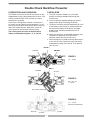
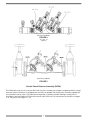
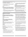
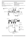
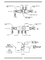
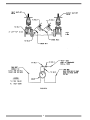
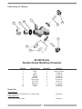
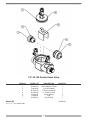
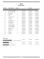
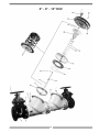
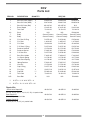
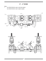
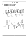
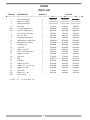
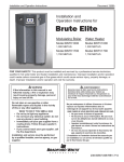
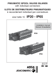
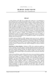
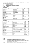
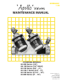
BFMM4001
1-08
MAINTENANCE MANUAL
COVERING MODELS:
40-300 Series (1/2”)
4S-100 Series (1/2” ONLY)
40-100 Series (3/4” - 2”)
40-100-T Series (3/4” - 2”)
40-100 Series (2-1/2” - 10”)
40-600 Series (3” - 10”)
Conbraco Industries, Inc.
P.O. Box 247
Matthews, NC 28106
Phone: (704) 841-6000
Fax 704-841-6020
www.conbraco.com
TABLE OF CONTENTS
Double Check Valve Backflow Preventer 1/2" - 10" &
Double Check Detector Assembly 3" - 10"
Section
Page
Description and Operation . . . . . . . . . . . . . . . . . . . . . . . . . . . . . . . . . . . . . . . . . . .2, 3
Installation . . . . . . . . . . . . . . . . . . . . . . . . . . . . . . . . . . . . . . . . . . . . . . . . . . . . . . . . .2
Trouble Shooting Guide . . . . . . . . . . . . . . . . . . . . . . . . . . . . . . . . . . . . . . . . . . . . . . .4
Maintenance Instructions 1/2" (40-103) . . . . . . . . . . . . . . . . . . . . . . . . . . . . . . . . . . .4
Maintenance Instructions 1/2" (4S-103) . . . . . . . . . . . . . . . . . . . . . . . . . . . . . . . . . .5
Maintenance Instructions 3/4" - 2" . . . . . . . . . . . . . . . . . . . . . . . . . . . . . . . . . . . . . .5
Maintenance Instructions 2-1/2" - 10" . . . . . . . . . . . . . . . . . . . . . . . . . . . . . . . . . . .6
Testing Procedure 1/2" - 10" . . . . . . . . . . . . . . . . . . . . . . . . . . . . . . . . . . . . . . .6 - 11
Parts Listing 40-300, 1/2” . . . . . . . . . . . . . . . . . . . . . . . . . . . . . . . . . . . . . . . . . . . .12
Parts Listing 4S-103, 1/2” . . . . . . . . . . . . . . . . . . . . . . . . . . . . . . . . . . . . . . . . . . . .13
Parts Listing 40-100, 3/4" - 2" . . . . . . . . . . . . . . . . . . . . . . . . . . . . . . . . . . . . .14 - 17
Parts Listing 2-1/2" - 10" . . . . . . . . . . . . . . . . . . . . . . . . . . . . . . . . . . . . . . . . .18 - 21
Parts Listing 3" - 10" DCDA . . . . . . . . . . . . . . . . . . . . . . . . . . . . . . . . . . . . . . .22 - 25
Warranty . . . . . . . . . . . . . . . . . . . . . . . . . . . . . . . . . . . . . . . . . . . . . . . . . . . . . . . . . .26
1
Double Check Backflow Preventer
I DESCRIPTION AND OPERATION
II INSTALLATION
The Double Check Valve (DCV) device consists of two
independently acting, spring loaded check valves. Two
resilient seated shut-off valves and four test cocks
complete the assembly.
Each check is designed to maintain a minimum of 1
psi across the valve during normal operation. If at any
time the pressure downstream of the device increases
above the supply pressure, both check valves will
close to prevent any backflow from occurring.
The various styles and sizes of Double Check
Valves are illustrated in figures 1, 2, 3, 4 and 5.
a. The DCV must be installed in an accessible
location to facilitate periodic field testing and
maintenance.
b. Flush all upstream piping thoroughly to remove
foreign matter prior to installing the device.
c. The device should be installed horizontally for ease
of maintenance and testing. A clearance between
the lower most portion of the device and flood
grade or floor should be provided for ease of
maintenance.
d. When shut-off valves are provided separately, they
should be installed with a test cock on the
upstream side of the inlet shut-off valve.
e. After installing the assembly and with downstream
or #2 shut-off valve closed, pressurize the device
and bleed air through test cock #4. Then open #2
shut-off valve.
99 PSIG
100 PSIG
98 PSIG
FIGURE 1
1/2" - 40-103
99 PSIG
100 PSIG
98 PSIG
FIGURE 2
(40 - 10X - A2)
Y - Pattern
(NO FLOW CONDITION)
FIGURE 3
1/2" - 4S-103
(NO FLOW CONDITION)
100 PSIG
98 PSIG
99 PSIG
2
(No Flow Condition)
FIGURE 4
40 - 10X - T2
Top Entry
(No Flow Condition)
FIGURE 5
Double Check Detector Assembly (DCDA)
The DCDA device consists of a mainline DCV and a by-pass assembly consisting of an approved DCV assembly
and water meter. Each device is equipped with test cocks for periodic field testing and is normally supplied with
inlet and outlet shut-off valves. For information on operation, installation, trouble shooting & testing refer to
Installation Instruction Booklet I476700 furnished with each DCDA unit. For maintenance instructions see pages
4 - 6. For parts list see pages 21 - 24.
3
III TROUBLE SHOOTING GUIDE
SYMPTOM
1. Check valve fails to hold
1 psid.
CAUSE
a. Shut-off valve not closed
completely.
b. Check valve fouled with
debris.
c. Check poppet stem not
moving freely in guide.
CORRECTIVE ACTION
a. Close #2 shut-off valve or
inspect for possible
through leakage.
b. Inspect and clean seat
disc and seat.
c. Inspect for debris or
deposit on poppet stem
or guide.
IV MAINTENANCE INSTRUCTIONS 1/2" (40-103)
A. Disassembly — Check Valves
1. Close #2 shut off valve, then close #1 shut-off valve.
2. Bleed pressure from the assembly by opening #2,
#3, and #4 test cock.
CAUTION:
Caps are spring loaded and should be removed
carefully to avoid personal injury.
3. Unscrew cap using hex head provided.
4. Remove spring and poppet assembly
from the body.
5. Remove the seat disc from the poppet.
B. Inspection
1. All parts should be carefully inspected for any
damage or excessive wear and thoroughly rinsed
in clean water prior to reassembly. Replace worn
parts as necessary.
C. Assembly — Check Valve Poppet
1. Install new disc in poppet.
NOTE:
Due to symmetry of the disc, the old disc may be
turned over to obtain an effective seal.
D. Assembly — Check Valve
1. Install the poppet assembly into the body.
2. Install the spring onto the poppet.
3. Apply a thin coat of FDA approved lubricant
on cap O-Ring.
4. Guide cap over spring and poppet stem and
tighten cap.
4
V MAINTENANCE INSTRUCTIONS 1/2" (4S-103)
Disassembly
1. Close inlet and outlet shut-off valves
2. Bleed pressure from the assembly by opening
#2, #3, and #4 test cock.
3. Unscrew and remove bronze cap.
4. Remove stainless steel spacer using lifting tab.
5. Remove first check module by pulling outward with
fingers (a small screwdriver may aid removal). Be
sure test cock #2 is open so as to prevent
hydraulic lock. Generally, the first check o-ring will
remain in the bore.
6. Remove second check assembly by sliding the
assembly out of its bore (a small screwdriver
placed in the groove provided will aid removal).
Be sure test cock #4 is open as to prevent
hydraulic lock.
Inspection
1. All parts should be carefully inspected for any
damage or excessive wear and thoroughly rinsed
in clean water prior to reassembly.
2. Replace all worn parts as necessary.
NOTE:
Check valve modules are not user serviceable. In
the event of check failure, replacement modules
are sold individually.
Assembly
1. Replace check modules, second check first then
first check. Make sure first check o-ring is installed.
(Tip: push o-ring to the bottom of the bore before
installing check module.) Press check module into
bore. A thin coat of FDA approved lubricant on
o-ring will aid insertion.
2. Replace stainless steel spacer.
3. Apply a thin coat of FDA approved lubricant on cap
o-ring. Replace Cap.
VI MAINTENANCE INSTRUCTIONS 3/4" - 2"
A. Disassembly — Check Valves
1. Close #2 shut off valve, then close #1 shut-off valve.
2. Bleed pressure from the assembly by opening
#2, #3 and #4 test cock.
CAUTION:
Caps are spring loaded and should be removed
carefully to avoid personal injury.
3. Unscrew cap using hex head provided.
4. Remove spring and poppet assembly from
the body.
B. Disassembly — Check Valve Poppet
CAUTION:
Do not use pliers or other tools which may
damage or scratch the plastic stem.
1. Holding the poppet assembly in one hand, remove
screw and retaining washer.
2. Remove the seat disc.
3. All parts should be carefully inspected for any
damage or excessive wear and thoroughly rinsed
in clean water prior to reassembly. Replace worn
parts as necessary.
C. Assembly — Check Valve Poppet
1. Install new disc in poppet and secure with washer
and screw.
D. Assembly — Check Valve
2. Place and center the poppet assembly in the body.
3. Install the spring onto the poppet.
4. Apply a thin coat of FDA approved lubricant on cap
O-Ring.
5. Guide cap over spring and poppet stem and
tighten cap.
5
VII MAINTENANCE INSTRUCTIONS 2-1/2" - 10"
A. Disassembly — Check Valves
1. Close #2 shut-off valve, then close #1 shut-off valve.
2. Bleed pressure from the assembly by opening #2,
#3, and #4 test cock.
3. Remove cover bolts and cover.
NOTE:
The spring load on the cover will be removed when
the cover bolts are backed off approximately 3/8".
4. Remove the complete check assembly straight out
of the valve body being careful not to damage the
seat ring.
5. The check valve seat is threaded into the body and
may be removed at this time if necessary (The seat
is bolted into the body on the 10" unit).
6. To remove the seat disc, remove the retaining plate
nut (On the 8" & 10" units remove the retaining
plate bolts) and retaining plate, remove disc.
WARNING:
The check valve spring is held in compression by
the stem nut on top. This nut should not be
removed unless the spring requires replacement.
B. Assembly — Check Valves
1. Install seat disc in holder and secure with retaining
plate and retaining nut or bolts as applicable.
NOTE:
Due to the symmetry of the disc, the old disc may
be turned over to obtain an effective seal.
2. Install the check valve assembly into the body.
3. Install the check valve cover and tighten bolts evenly.
VIII TESTING PROCEDURES
NOTE:
It is important that the DCV device be tested
periodically in compliance with local codes, but at
least once a year or more, as service conditions
warrant.
5. Slowly open by-pass valve #1 and lower the
pressure at test cock #2 approximately 2 psi below
the pressure at test cock #3. Note: Due to check
valve disc compression, both “high” and “low” side
gauges may drop at the same rate approximately
10-15 psi or more. After the check valve disc
compresses fully the required “high” side pressure
of 2 psi below the “low” side should be obtainable.
If this pressure differential can be maintained then
check valve #1 is reported as “tight” or “okay”.
Proceed to test no. 2. However, if this pressure
differential cannot be maintained proceed to step
no. 6.
6. Open #1 shut-off valve to repressurize the device.
7. Loosely attach the vent hose to test cock #1. Bleed
all air from the gauge and vent hose by opening
by-pass valve #2. Close by-pass valve #2, tighten
vent hose. Open test cock #1.
8. Close #1 shut-off valve.
9. Loosen the “low” side hose at test cock #3 and
lower the pressure in the assembly approximately
10 psi. Retighten hose.
10.Simultaneously open by-pass valves #1 and #2 very
slowly. If the check valve is holding tight the “high”
side gauge will begin to drop while the “low” side
gauge will rise. Close both by-pass valves. If a small
(no more than 5 psi) pressure differential is created
and held, then the check valve is reported as “tight”
or “okay.” If a pressure differential cannot be
maintained the check valve is reported as leaking.
METHOD 1 (Duplex Gauge)
NOTE:
Test set-up is illustrated in Figure 5 for 1/2"
through 2" and Figure 6 for 2-1/2 through 10".
EQUIPMENT REQUIRED:
Conbraco double check backflow preventer test kit.
NOTE:
All connections must be free from leaks in order to
achieve accurate readings during testing.
TEST NO. 1:
Purpose:
To test check valve #1 for tightness against reverse flow.
Requirement:
The valve shall permit no through leakage in a
direction reverse normal flow under all conditions
of a pressure differential.
PROCEDURE:
1. Bleed water through all four test cocks to flush any
foreign material.
2. Connect the “high” side hose to test cock #2.
Connect the “low” side hose to test cock #3.
3. Open test cocks #2 and #3. Bleed both hoses,
making sure to bleed the low side last.
4. Close #2 shut-off valve, then close #1 shut-off valve.
6
TEST NO. 2:
Purpose:
To test check valve #2 for tightness against reverse flow.
Requirement:
The valve shall permit no through leakage in a
direction reverse to normal flow under all conditions of
a pressure differential.
PROCEDURE:
Same as test #1 except the “high” side hose is
connected to test cock #3 and the “low” side
connected to test cock #4.
RESTORE OPERATION:
Close all test cocks. Remove testing equipment. Open
shut-off valves #1 and #2.
Check
#2
Check
#1
#1 Shut-Off
Valve
#2 Shut-Off
Valve
TC #1
TC #3
TC #2
TC #4
“Low” Side
Connect To:
TC #3 for Test #1
TC #4 for Test #2
“High” Side
Connect To:
TC #2 for Test #1
TC #3 for Test #2
“Vent” Hose
Connected in
Procedure
Steps
#7-#10 Only
“Vent” Hose
(Open to Atmosphere
During Test No. 1)
Legend
Hydraulic Hose
By-Pass (BP) Valve
TC
Test Cock
Duplex Gauge or Two
Bourdon Tube Gauges
BP #1
BP #2
“Drain” Hose
FIGURE 5
7
DOUBLE CHECK VALVE
8
METHOD 2
NOTE:
Test set-up is illustrated in Figure 7 for 1/2"
through 2" and Figure 8 for 2-1/2 through 10".
EQUIPMENT REQUIRED:
Differential pressure gauge type test kit such as
Conbraco Model No. 40-200-TKU or 40-200-TK5U.
NOTE:
For all testing, the gauge and open ends of hoses
not being used must be held at the same level as
the assembly being tested.
TEST NO. 1:
Purpose:
To determine the static pressure drop across check
valve No. 1.
Requirement:
The static Pressure drop across check valve No. 1
shall be at least 1 psid.
PROCEDURE:
1. To eliminate foreign material, flush all four test
cocks, one at a time.
2. Open test valves No. 1 and No. 2 on the gauge
and close test valve No. 3. Attach “high” side hose
to test cock No. 2.
3. Bleed all air from hose and gauge by slowly
opening test cock No.2. Then slowly close test
valve No. 2.
4. Close the outlet shut-off valve. Then close the inlet
shut-off valve.
5. Slowly open test cock No. 3. After the gauge
reading stabilizes and water stops running out of
test cock No. 3, the static pressure drop across the
check valve indicated by the gauge and is
recorded as such.
NOTE: If water continues to discharge from test
cock No. 3 then a leaky shut-off valve is evident
and should be repaired or bypassed before testing
continues. If the water recedes from the test cock
opening then move the gauge to a point level with
the centerline of the check seat area and record
the gauge reading as the static pressure
differential across check No. 1.
TEST NO. 2:
Purpose:
To determine the static pressure drop across check
valve No. 2.
Requirement:
The static pressure drop across check valve No. 2
shall be at least 1 psid.
PROCEDURE:
1. Open test valves No. 1 and No. 2 on the gauge
and close test valve No. 3. Attach "high" side hose
to test cock No. 3.
2. Bleed all air from hose and gauge by slowly
opening test cock No. 3. Then slowly close test
valve No. 2.
3. Close the outlet shut-off valve. Then close the inlet
shut-off valve.
4. Slowly open test cock No. 4. After the gauge
reading stabilizes and water stops running out of
test cock No. 4, the static pressure drop across the
check valve is indicated by the gauge and is
recorded as such.
NOTE: If water continues to discharge from test cock
No. 4 then a leaky shut-off valve is evident and should
be repaired or bypassed before testing continues. If
the water recedes from the test cock opening then
move the gauge to a point level with the centerline of
the check seat area and record the gauge reading as
the static pressure differential across check No. 2.
9
FIGURE 7
10
FIGURE 8
11
Parts Listing 1/2" (Bronze)
7
8
9
10
2
3
6
5
4
40-300 Series
Double Check Backflow Preventer
ITEM NO.
DESCRIPTION
QUANTITY
1
2
3
4
5
6
7
8
9
10
Body
Cap
Spring
Poppet
Seat Disc
Cap O-Ring
Test Cock
Union Nut
Tail Piece
Seal
1
2
2
2
2
2
3
1
1
1
PART NO.
1/2"
Consult Factory
F-3009-06
A-1750-00
K-3404-00
D-2600-00
D-2501-00
78-257-01
C-1778-06
L-5226-06
D-2607-00
Repair Kits
Major Repair Kit
(3 (2), 6 (2), part no. W-6759-06 (2)), n/s packet lube
Rubber Repair Kit
(5 (2), 6 (2)), n/s packet lube
40-300-02
40-300-01
12
1/2" 4S-103 Double Check Valve
ITEM NO.
PARTS LIST.
DESCRIPTION
QUANTITY
1
2
3
4
5
6
7
D-3885-00
F-3228-00
W-4302-00
D-2422-00
L-6104-00
F-3206-05
D-2568-00
Check Module O-Ring
1st Check Module
2nd Check Assembly
2nd Check O-Ring
Check Spacer
Cap
Cap O-Ring
1
1
1
1
1
1
1
Repair Kit
4S-003-01
1, 2, 3, 4, 7, n/s packet lube
13
Parts Listing 3/4" - 2" (Bronze)
2
4
5
6
7
3
10
1
11
9
8
14
40-100
Double Check Backflow Preventer
ITEM NO.
1
2
n/s
3
4
5
6
7
8
9
10
11
DESCRIPTION
QUANTITY
Body
1
Cap
Plug
Spring
Poppet
Seat Disc
Seat Retainer
Screw
Cap O-Ring
Test Cock
Check Seat
Check O-Ring
2
2
2
2
2
2
2
2
3
2
2
PART NO.
3/4" & 1"
Consult
Factory
F-310805*
K-301200*
A-170000
K-336200
D-250300
D-249900
B-175000
D-250000
78-257-01
L-486400
D-227400
1-1/4", 1-1/2", 2"
Consult
Factory
F-311505**
K301900**
A-170100
K-336700
D-250800
D-250900
B-175000
D-251000
78-258-01
L-486600
D-256500
40-004-A5
40-007-A5
40-004-A2
40-007-A2
40-004-A6
40-007-A6
40-004-A8
40-007-A8
Repair Kits
Major Repair Kit
(4 (2), 5 (2), 6 (2), 7 (2), 8 (2),
10 (2), 11 (2)), n/s packet lube
Check Valve Repair Kit
(4, 5, 6, 7, 8, 10, 11), n/s packet lube
Rubber Repair Kit
(5 (2), 8 (2), 11 (2)), n/s packet lube
Replaceable Seat Kit
(10 (2), 11 (2)), n/s packet lube
Accessories
Double Check Valve Test Kit
40-200-TKU (3-Valve)
40-200-TK5U (5-Valve)
* 1/8” NPT plub needed for units without top mounted test cocks.
** 1/4” NPT plug needed for units without top mounted test cocks.
15
Parts Listing 3/4" - 2" (Bronze) Top Entry
9
4
5
2
6
8
7
3
10
11
1
16
40-100-T SERIES
TOP ENTRY DOUBLE CHECK VALVE ASSEMBLY
ITEM NO.
DESCRIPTION
QUANTITY
1
Body
1
2
3
4
5
6
7
8
9
10
11
Cap
Spring
Poppet
Seat Disc
Seat Retainer
Screw
Cap O-Ring
Test Cock
Check Seat
Check O-Ring
2
2
2
2
2
2
2
3
2
2
PART NO.
3/4" & 1"
Consult
Factory
F-3108-05
A-1700-00
K-3362-00
D-2503-00
D-2499-00
B-1750-00
D-2500-00
78-257-01
L-4864-00
D-2274-00
1-1/4", 1-1/2", 2"
Consult
Factory
F-3115-05
A-1701-00
K-3367-00
D-2508-00
D-2509-00
B-1750-00
D-2510-00
78-258-01
L-4866-00
D-2565-00
40-004-A5
40-007-A5
40-004-A2
40-007-A2
40-004-A6
40-007-A6
40-004-A8
40-007-A8
Repair Kits
Major Repair Kit
(4 (2), 5 (2), 6 (2), 7 (2), 8 (2), 10 (2), 11 (2)), n/s packet lube
Check Valve Repair Kit
(4, 5, 6, 7, 8,10, 11), n/s packet lube
Rubber Repair Kit
(5 (2), 8 (2), 11 (2)), n/s packet lube
Replaceable Seat Kit
(10 (2), 11 (2)), n/s packet lube
Accessories
Double Check Valve Test Kit
40-200-TKU (3-Valve)
40-200-TK5U (5-Valve)
17
Parts Listing 2-1/2" - 10" (Ductile Iron)
2 1/2" - 3" - 4" DCV
18
DCV
Parts List
ITEM NO.
1
1
1
2
3
7
10
11
12
13
14
15
16
17
18
19
20
21
22
23
24
25
DESCRIPTION
QUANTITY
Shut-Off Valve (OS&Y)
Shut-Off Valve (NRS)
Shut-Off Valve (Ball)
Brass Nipple
Test Cock
Body
C.V. Seat O-Ring
C.V. Seat
C.V. Stem
C.V. Stem O-Ring
Retainer Nut
Retainer Washer
C.V. Seat Disc
Seat Disc Holder
1st Check Spring
2nd Check Spring
Spring Retainer
Jam Nut
Cap O-Ring
C.V. Cap
Cap Bolt
Test Cock
2
2
2
1
1
1
2
2
2
2
2
2
2
2
1
1
2
2
2
2
12
3
2-1/2"
W-6789-00
W-6785-00
6Q-209-01
K-3406-00
70-103-01
Q-4526-19
D-2576-00
L-4637-05
G-3239-06
D-2561-00
C-1756-00
E-2199-00
D-2560-00
F-3000-05
A-1741-00
A-1741-00
E-2198-05
C-1589-05
D-2566-00
Q-4530-19
B-1797-00
70-803-10
PART NO.
3"
W-6790-00
W-6786-00
6Q-200-01
K-3406-00
70-103-01
Q-4527-19
D-2567-00
L-4637-05
G-3239-00
D-2561-00
C-1756-00
E-2199-00
D-2560-00
F-3000-05
A-1741-00
A-1741-00
E-2198-05
C-1589-05
D-2566-00
Q-4530-19
B-1797-00
70-803-10
4"
W-6824-00
W-6743-00
6Q-20A-01
K-3406-00
70-103-01
Q-4534-19
D-2573-00
L-4640-05
G-3242-00
D-2561-00
C-1756-00
E-2204-00
D-2572-00
F-3001-05
A-1744-00
A-1744-00
E-2202-05
C-1589-05
D-2574-00
Q-4533-19
B-1801-00
70-803-10
40-009-02
40-009-02
40-00A-02
40-009-03
40-009-03
40-00A-03
40-009-04
40-009-04
40-00A-04
Repair Kits
1st Check Valve Repair Kit
(12, 13, 14, 15, 16, 17, 18, 20, 21, 22), n/s packet lube
Seat Repair Kit
(10, 11, 22), n/s packet lube
Rubber Repair Kit
2 each (10, 13, 16, 22), n/s packet lube
19
6" - 8" - 10" DCV
20
DCV
Parts List
ITEM NO.
1
1
1
2
3
6A
7
7A
10
11
12
13
14
15
16
17
18
19
20
21
22
23
24
25
N/S
***
****
DESCRIPTION
QUANTITY
Shut-Off Valve (OS&Y)
Shut-Off Valve (NRS)
Shut-Off Valve (Ball)
Brass Nipple
Test Cock
Stud
Body
Body
C.V. Seat O-Ring
C.V. Seat
C.V. Stem
C.V. Stem O-Ring
Retainer Nut/Bolt
Retainer Washer
C.V. Seat Disc
Seat Disc Holder
1st Check Spring
2nd Check Spring
Spring Retainer
Jam Nut
Cap O-Ring
C.V. Cap
Cap Bolt
Test Cock
Seat Bolt
2
2
2
1
1
2
1
1
2
2
2
2
***
2
2
2
1
1
2
2
2
2
****
3
12
6"
W-6825-00
W-6744-00
6Q-20C-01
K-3412-40
70-104-10
N/A
Consult Factory
Consult Factory
D-2576-00
L-4644-05
G-3246-00
D-2578-00
C-1760-00
E-2205-00
D-2575-00
F-3002-05
A-1746-00
A-1746-00
E-2203-05
C-1706-00
D-2577-00
Q-4537-19
B-1800-00
70-804-10
N/A
PART NO.
8"
W-6826-00
W-6827-00
6Q-20E-01
K-3412-00
70-104-10
N/A
Consult Factory
Consult Factory
D-2589-00
L-4653-05
G-3273-00
D-2587-00
B-1754-00
E-2208-00
D-2586-00
F-3008-05
A-1748-00
A-1748-00
E-2207-05
C-1763-00
D-2588-00
Q-4545-19
B-1690-00
70-804-10
N/A
10"
W-6859-00
W-6858-00
N/A
K-3412-00
70-104-10
B-2036-00
Consult Factory
Consult Factory
D-2588-00
L-4759-05
G-3305-00
D-2587-00
B-1754-00
E-2229-00
D-2649-00
F-3019-05
A-1779-00
A-1779-00
E-2228-05
C-1763-00
D-2651-00
Q-4574-19
B-1881-00
70-804-10
B184900
40-00E-02
40-00G-02
40-00E-03
40-00G-03
40-00E-04
40-00G-04
6" QTY = 2 / 8" & 10" QTY = 8
6" QTY = 12 / 8" & 10" QTY = 24
Repair Kits
Check Valve Repair Kit
40-00C-02
(12, 13, 14, 15, 16, 17, 18, 20, 21, 22), n/s packet lube
40-00C-03
Seat Repair Kit
(10, 11, 22), n/s packet lube
40-00C-04
Rubber Repair Kit
2 each (10, 13, 16, 22), n/s packet lube
21
3" - 4" DCDA
Notes:
1.
Use P/N W-7062-00 for meter in cubic feet register.
Use P/N W-7094-00 for meter in gallons register.
22
DCDA
Parts List
ITEM NO.
DESCRIPTION
1
2
3
N/S
N/S
6
7
8
9
9
10
11
12
13
N/S
15
16
17
18
22
23
24
25
N/S
N/S
N/S
N/S
N/S
N/S
N/S
Gate Valve (OS&Y)
DCDA Body
Test Cock
1st Chk Poppet Ass’y
2nd Chk Poppet Ass’y
By-Pass Shut-Off Valve
Tee, Reducing
Coupling, Water Meter
Water Meter in Cubic Feet
Water Meter in Gallons
3/4" DCV
Elbow, Street
By-Pass Shut-Off Valve
Swivel Nut
Washer, Meter
Coupling
3/4" Coupling
Nipple, Close
Test Cock
Cap
Cap Bolt
Nipple
Test Cock
Nipple, 3/4" x 3" Lg.
Elbow, 3/4" - 90°
Cap O-Ring
Seat O-Ring
Plug, 1/2"
Check Valve Seat
Meter to DCV Adapter
*
**
3" QTY = 3 / 4" QTY = 1
3" QTY = 2 / 4" QTY = 4
QUANTITY
2
1
3
1
1
1
1
1
1
1
1
*
1
1
1
1
2
**
1
2
12
1
1
2
1
2
2
1
2
1
23
PART NO.
3"
W679000
Contact Factory
7080310
W710705
W671805
7B10401
K350600
K350500
W706200
W709400
W378905
K350200
7B10431
N/A
N/A
N/A
N/A
K337000
7010310
Q453019
B179700
K340600
7825701
K341200
K350100
D256600
D256700
K300800
L463705
L522806
4"
W682400
Contact Factory
7080310
W710005
W673105
7B10401
K350600
K350500
W706200
W709400
W738905
K350200
7B10431
C186705
D261000
K379106
K350400
K337000
7010310
Q453319
B180100
K340600
7825701
N/A
N/A
D257400
D257300
K300800
L464005
N/A
6" - 8” - 10" DCDA
Notes:
1.
Use P/N W-7062-00 for meter in cubic feet register.
Use P/N W-7094-00 for meter in gallons register.
24
DCDA
Parts List
ITEM NO.
1
2
3
4
N/S
N/S
7
8
9
10
10
11
12
13
14
15
16
20
21
22
23
24
25
N/S
N/S
DESCRIPTION
Gate Valve (OS&Y)
Body (1st Check)
Body (2nd Check)
Ball Valve
1st Chk Poppet Ass’y
2nd Chk Poppet Ass’y
By-Pass Shut-Off Valve
Tee, 3/4" NPT
Coupling, Water Meter
Water Meter in Cubic Feet
Water Meter in Gallons
Coupling, 3/4"
3/4" DCV
Elbow, 3/4" NPT
By-Pass Shut-Off Valve
Nipple, 3/4" NPT
Ball Valve
Cap
Cap Bolt
Nipple, 3/4" NPT
Nipple, 3/4" x 5-1/2" Lg.
Nipple, 3/4" NPT
Test Cock
Elbow, 3/4" - 90°
Cap O-Ring
QUANTITY
2
1
1
3
1
1
1
1
2
1
1
1
1
1
1
2
1
2
*
1
1
1
1
1
* 6" QTY = 12 / 8" & 10" QTY = 24
25
6"
W682500
PART NO.
8"
10"
W682600
W685900
Contact Factory
Contact Factory
Contact Factory
Contact Factory
Contact Factory
Contact Factory
7080410
W706605
W674205
7B10401
K351100
K350500
W706200
W709400
K350400
W738905
K350100
7B10431
K350900
7010410
Q453719
B180000
K341200
K350900
K350900
7825701
K350100
7080410
W708505
W674605
7B10401
K351100
K350500
W706200
W709400
K350400
W738905
K350100
7B10431
K352700
7010410
Q454519
B169000
K341200
K350900
K350900
7825701
K350100
7080410
W711305
W685705
7B10401
K351100
K350500
W706200
W709400
K350400
W738905
K350100
7B10431
K356000
7010410
Q457419
B188100
K341200
K350900
K355900
7825701
K350100
Conbraco Industries Statement of
Warranty & Limitation of Liability
Conbraco Industries Inc. warrants, to its initial purchaser only, that its products which are delivered to this initial
purchaser will be of the kind described in the order or price list and will be free of defects in workmanship or
material for a period of two years from the date of delivery to you, our initial purchaser.
Should any failure to conform to this warranty appear within two years after the date of the initial delivery to our
initial purchaser, Conbraco will, upon written notification thereof and substantiation that the goods have been
stored, installed, maintained and operated in accordance with Conbraco’s recommendations and standard
industry practice, correct such defects by suitable repair or replacements at Conbraco’s own expense.
THIS WARRANTY IS EXCLUSIVE AND IS IN LIEU OF ANY IMPLIED WARRANTY OF MERCHANTABILITY,
FITNESS FOR A PARTICULAR PURPOSE OR OTHER WARRANTY OF QUALITY, WHETHER EXPRESSED OR
IMPLIED, EXCEPT THE WARRANTY OF TITLE AND AGAINST PATENT INFRINGEMENT. Correction of nonconformities in the manner and for the period of time provided above, shall constitute fulfillment of all liabilities of
Conbraco to our initial purchaser, with respect to the goods, whether based on contract, negligence, strict tort or
otherwise. It is the intention of Conbraco Industries, Inc. that no warranty of any kind, whether, express or
implied, shall pass through our initial purchaser to any other person or corporation.
LIMITATION OF LIABILITY: Conbraco Industries, Inc. SHALL NOT UNDER ANY CIRCUMSTANCES BE LIABLE
FOR SPECIAL OR CONSEQUENTIAL DAMAGES SUCH AS, BUT NOT LIMITED TO, DAMAGES OR LOSS OF
OTHER PROPERTY OR EQUIPMENT, LOSS OF PROFITS OR REVENUE, COST OF CAPITAL, COST OF
PURCHASED OR REPLACEMENTS GOODS, OR CLAIMS OF CUSTOMERS OF OUR INITIAL PURCHASER,
AND ALL OTHERS, SET FORTH HEREIN ARE EXCLUSIVE, AND THE LIABILITY OF CONBRACO WITH
RESPECT TO SAME SHALL NOT, EXCEPT AS EXPRESSLY PROVIDED HEREIN, EXCEED THE PRICE OF THE
GOODS UPON WHICH SUCH LIABILITY IS BASED.
26
SERVICE AND SALES DEPARTMENT
P.O. Box 247 • Matthews, NC 28106
Phone: 704-841-6000 • Fax: 704-841-6020
Southeast
Region
Florida
Georgia/Alabama
North Carolina/South Carolina/Tennessee-East
Virginia/Maryland/Washington, D.C./WV-East
[email protected]
[email protected]
[email protected]
[email protected]
813-792-5060
770-447-1227
864-578-4334
804-213-3801
813-792-5213
770-263-6899
864-578-4889
804-213-3802
Southern
Region
Southern Marketing Group
AVC Mechanical Sales, Inc.
Armstrong/Weatherly Associates
MS/TN-West/AR/Bowie Cty.-TX
Oklahoma/Texas-North
Texas-South/Louisiana
[email protected]
[email protected]
[email protected]
901-547-0042
214-201-0100
713-692-5566
901-547-0035
214-201-0104
713-692-6021
HEBCO, Inc.
New Tech Marketing
New Tech Marketing
Whitfill-McCarthy, LLC
V.E. Sales Co., Inc.
Fourmation Sales
WilIco, Inc.
Midwest Spec
Kansas/Missouri-West
IL/WI-East/IN-North/MI-Upper Peninsula/IA-/River Counties
Eastern Missouri/Southern Illinois
Kentucky/Indiana-South/Ohio-South
Michigan (Except Upper Peninsula)
Minnesota/North & South Dakota/Wisconsin-West
Nebraska/Iowa (Except River Counties)
Ohio-North/Pennsylvania-West/West Virginia-West
[email protected]
[email protected]
[email protected]
[email protected]
[email protected]
[email protected]
[email protected]
[email protected]
913-491-0797
630-378-4300
618-394-0329
502-459-4545
586-774-7760
763-262-4700
402-573-7000
330-538-0406
913-491-5126
630-378-0343
618-394-0427
502-459-9944
586-774-1490
763-262-4740
402-573-7371
330-538-0410
Elmco and Associates
Spec Management Group
Cisco Speciality Products, Inc.
Marshall-Rodeno Associated
Braley-Gray & Associates
Braley-Gray Washington
Southwestern Industrial Sales Co.
Jack Prust Sales
Active Sales Northwest, Inc
California-North
California-South (Irrigation), Hawaii (All Products)
California-South
CO/WY/MT/ID-SE/UT/NV-NE/NM/El Paso-TX
Oregon/SW Washington/Western Idaho
Alaska/Washington
Arizona/Nevada-SW
California-North (Irrigation)
Oregon, WA, Western Idaho (Irrigation)
[email protected]
[email protected]
[email protected]
[email protected]
[email protected]
[email protected]
[email protected]
[email protected]
[email protected]
916-383-0110
949-481-4225
714-921-9228
303-575-6701
503-249-6972
206-405-4370
480-458-5838
530-878-2922
541-726-0320
916-383-0181
949-487-0990
714-921-0442
303-575-6706
503-288-4464
206-405-4390
480-458-5843
530-878-2341
541-726-1148
Urell, Inc.
McMahon Marketing, Inc.
Continuous Sales Corporation
Layden Company
Keith Engle & Associates
Massachusetts/New England States
New York-Upstate/New York-West
New York-East/New Jersey-North
Pennsylvania-East/Delaware/New Jersey-South
OEM accounts
[email protected]
[email protected]
[email protected]
[email protected]
[email protected]
617-923-9500
518-792-3350
516-575-6800
610-363-6657
610-827-9560
617-926-9414
518-792-3351
516-349-8411
877-529-3361
610-827-9561
Conbraco Industries, Canada
Barclay Sales Ltd.
Dynamic Agencies, Ltd.
Tom Beggs Agencies Ltd.
Task Controls, Inc.
Agences J. Pierre Sylvain, Inc.
Kern Industries, Ltd.
Kern Industries Calgary, Ltd.
J. Levandier Sales, Inc.
[email protected]
[email protected]
[email protected]
[email protected]
[email protected]
[email protected]
[email protected]
[email protected]
905-761-6161
604-945-1010
306-343-1901
204-953-1900
416-291-3004
450-655-9588
780-451-2056
403-730-7791
905-761-6666
604-945-3030
306-343-1901
204-774-6915
416-754-3481
450-641-2737
780-454-6687
403-239-8179
Key to the North Sales Agency, Inc.
Steam and Industrial Equipment
160 Pennsylvania Ave., Unit 3, Concord, Ontario L4K 4A9
British Columbia
Saskatchewan
Manitoba/NW Ontario
Ontario
Quebec
Alberta-North
Alberta-South
Nova Scotia, New Brunswick, Prince Edward Island and
Newfoundland
Ontario-North
Ottawa
[email protected]
[email protected]
[email protected]
506-858-1615
705-524-6714
1-800-363-8482
506-858-1084
705-566-0148
514-457-7111
Rafael Rodriguez Barril, Inc.
Conbraco International Limited
Puerto Rico
Manchester, England
[email protected]
[email protected]
787-982-1550
44-161-212-3745
787-982-1570
+44-161-212-3747
Int’l./
Puerto Rico
Canada
B. Lynch & Associates
Spotswood Associates
Pro Marketing, Inc.
Mid South Marketing, Inc.
Midwestern Region
Fax
Western Region
Phone
Northeast
Region
E-Mail Address
For Representatives And Distributors In Your International Area
Please Contact The Closest Conbraco Industries International Office.
Conway, SC • Matthews, NC • Pageland, SC • Customer Service 1-704-841-6000 • www.apollovalves.com
Printed in USA COPYRIGHT 1/08
BP 5M
BFMM4001