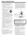
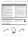
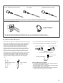
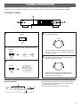
1
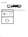
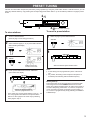
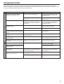
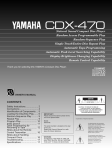
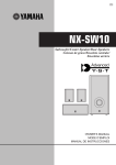
TX-470
Natural Sound AM/FM Stereo Tuner
40 Station Random Access Preset Tuning
Automatic Preset Tuning for FM Stations
Multi-Status Station Memory
Rotary Encoder Tuning
Direct PLL Synthesizer Tuning
Thank you for selecting this YAMAHA stereo tuner.
CAUTION
RISK OF ELECTRIC SHOCK
DO NOT OPEN
CAUTION: TO REDUCE THE RISK OF
ELECTRIC SHOCK, DO NOT REMOVE
COVER (OR BACK), NO USER-SERVICEABLE
PARTS INSIDE, REFER SERVICING TO
QUALIFIED SERVICE PERSONNEL.
OWNER’S MANUAL
IMPORTANT!
Please record the serial number of this
unit in the space below.
• Explanation of Graphical Symbols
CONTENTS
Safety Instructions ...................2
Supplied Accessories ..............3
Connections.............................4
Tuning Operations ...................7
Preset Tuning...........................9
Troubleshooting .....................11
Specifications ........................12
Model:
Serial No.:
The serial number is located on the rear
of the unit.
Retain this Owner’s Manual in a safe
place for future reference.
WARNING
TO REDUCE THE RISK OF FIRE OR
ELECTRIC SHOCK, DO NOT EXPOSE
THIS UNIT TO RAIN OR MOISTURE.
The lightning flash with arrowhead
symbol, within an equilateral triangle,
is intended to alert you to the
presence of uninsulated “dangerous
voltage” within the product’s
enclosure that may be of sufficient
magnitude to constitute a risk of
electric shock to persons.
The exclamation point within an
equilateral triangle is intended to alert
you to the presence of important
operating and maintenance
(servicing) instructions in the
literature accompanying the
appliance.
SAFETY INSTRUCTIONS
1
2
3
4
5
6
6A
7
8
9
10
11
12
13
14
15
A.
B.
C.
D.
E.
16
17
2
Read Instructions – All the safety and operating
instructions should be read before the unit is operated.
Retain Instructions – The safety and operating instructions
should be retained for future reference.
Heed Warnings – All warnings on the unit and in the
operating instructions should be adhered to.
Follow Instructions – All operating and other instructions
should be followed.
Water and Moisture – The unit should not be used near
water – for example, near a bathtub, washbowl, kitchen
sink, laundry tub, in a wet basement, or near a swimming
pool, etc.
Carts and Stands – The unit should be used only with a
cart or stand that is recommended by the manufacturer.
A unit and cart combination should
be moved with care. Quick stops,
excessive force, and uneven
surfaces may cause the unit and
cart combination to overturn.
Wall or Ceiling Mounting – The unit
should be mounted to a wall or ceiling only as
recommended by the manufacturer.
Ventilation – The unit should be situated so that its
location or position does not interfere with its proper
ventilation. For example, the unit should not be situated
on a bed, sofa, rug, or similar surface, that may block the
ventilation openings; or placed in a built-in installation,
such as a bookcase or cabinet that may impede the flow
of air through the ventilation openings.
Heat – The unit should be situated away from heat
sources such as radiators, stoves, or other appliances that
produce heat.
Power Sources – The unit should be connected to a power
supply only of the type described in the operating
instructions or as marked on the unit.
Power-Cord Protection – Power-supply cords should be
routed so that they are not likely to be walked on or
pinched by items placed upon or against them, paying
particular attention to cords at plugs, convenience
receptacles, and the point where they exit from the unit.
Cleaning – The unit should be cleaned only as
recommended by the manufacturer.
Nonuse Periods – The power cord of the unit should be
unplugged from the outlet when left unused for a long
period of time.
Object and Liquid Entry – Care should be taken so that
objects do not fall into and liquids are not spilled into the
inside of the unit.
Damage Requiring Service – The unit should be serviced
by qualified service personnel when:
The power-supply cord or the plug has been damaged;
or
Objects have fallen, or liquid has been spilled into the unit;
or
The unit has been exposed to rain; or
The unit does not appear to operate normally or exhibits a
marked change in performance; or
The unit has been dropped, or the cabinet damaged.
Servicing – The user should not attempt to service the unit
beyond those means described in the operating
instructions. All other servicing should be referred to
qualified service personnel.
Power Lines – An outdoor antenna should be located
away from power lines.
18 Grounding or Polarization – Precautions should be taken
so that the grounding or polarization is not defeated.
19 Outdoor Antenna Grounding – If an outside antenna is
connected to this unit, be sure the antenna system is
grounded so as to provide some protection against voltage
surges and built-up static charges. Article 810 of the
National Electrical Code, ANSI/NFPA 70, provides
information with regard to proper grounding of the mast
and supporting structure, grounding of the lead-in wire to
an antenna discharge unit, size of grounding conductors,
location of antenna discharge unit, connection to
grounding electrodes, and requirements for the grounding
electrode.
EXAMPLE OF ANTENNA GROUNDING
MAST
ANTENNA
LEAD IN
WIRE
GROUND
CLAMP
ANTENNA
DISCHARGE UNIT
(NEC SECTION 810–20)
ELECTRIC
SERVICE
EQUIPMENT
GROUNDING CONDUCTORS
(NEC SECTION 810–21)
GROUND CLAMPS
POWER SERVICE GROUNDING
ELECTRODE SYSTEM
(NEC ART 250. PART H)
NEC – NATIONAL ELECTRICAL CODE
Note to CATV system installer:
This reminder is provided to call the CATV system
installer's attention to Article 820-40 of the NEC that
provides guidelines for proper grounding and, in
particular, specifies that the cable ground shall be
connected to the grounding system of the building, as close
to the point of cable entry as practical.
CAUTION: READ THIS BEFORE OPERATING
YOUR UNIT
1
2
3
4
5
6
To ensure the finest performance, please read this
manual carefully. Keep it in a safe place for future
reference.
Install your unit in a cool, dry, clean place – away from
windows, heat sources, and too much vibration, dust,
moisture or cold. Avoid sources of hum (transformers,
motors). To prevent fire or electrical shock, do not
expose to rain and water.
Do not operate the unit upside-down. It may overheat,
possibly causing damage.
Never open the cabinet. If a foreign object drops into
the set, contact your dealer.
Do not use force on switches, knobs or cords. When
moving the set, first turn the unit off. Then gently
disconnect the power plug and the cords connecting to
other equipment. Never pull the cord itself.
Do not attempt to clean the unit with chemical solvents;
this might damage the finish. Use a clean, dry cloth.
7
To prevent lightning damage, pull out the power cord and
remove the antenna cable during an electrical storm.
8
Be sure to read the “TROUBLESHOOTING” section on
common operating errors before concluding that your unit
is faulty.
FCC INFORMATION
1. IMPORTANT NOTICE : DO NOT MODIFY THIS UNIT!
This product, when installed as indicated in the
instructions contained in this manual, meets FCC
requirements. Modifications not expressly approved by
Yamaha may void your authority, granted by the FCC, to
use the product.
2. IMPORTANT : When connecting this product to
accessories and/or another product use only high quality
shielded cables. Cable/s supplied with this product
MUST be used. Follow all installation instructions.
Failure to follow instructions could void your FCC
authorization to use this product in the USA.
3. NOTE : This product has been tested and found to
comply with the requirements listed in FCC Regulations,
Part 15 for Class “B” digital devices. Compliance with
these requirements provides a reasonable level of
assurance that your use of this product in a residential
environment will not result in harmful interference with
other electronic devices.
This equipment generates/uses radio frequencies and, if
not installed and used according to the instructions
found in the users manual, may cause interference
harmful to the operation of other electronic devices.
Compliance with FCC regulations does not guarantee that
interference will not occur in all installations. If this product
is found to be the source of interference, which can be
determined by turning the unit “OFF” and “ON”, please try
to eliminate the problem by using one of the following
measures:
Relocate either this product or the device that is being
affected by the interference.
Utilize power outlets that are on different branch (circuit
breaker or fuse) circuits or install AC line filter/s.
In the case of radio or TV interference, relocate/reorient the
antenna. If the antenna lead-in is 300 ohm ribbon lead,
change the lead-in to coaxial type cable.
If these corrective measures do not produce satisfactory
results, please contact the local retailer authorized to
distribute this type of product. If you can not locate the
appropriate retailer, please contact Yamaha Electronics
Corp., U.S.A. 6660 Orangethorpe Ave, Buena Park, CA
90620.
The above statements apply ONLY to those products
distributed by Yamaha Corporation of America or its
subsidiaries.
We Want You Listening For A Lifetime
YAMAHA and the Electronic Industries Association’s
Consumer Electronics Group want you to get the most out of
your equipment by playing it at a safe level. One that lets the
sound come through loud and clear without annoying blaring or
distortion – and, most importantly, without affecting your
sensitive hearing. Since hearing damage from loud sounds is
often undetectable until it is too late, YAMAHA
and the Electronic Industries Association’s
Consumer Electronics Group recommend you to
avoid prolonged exposure from excessive
volume levels.
SUPPLIED ACCESSORIES
After unpacking, check that the following parts are contained.
Indoor FM Antenna
AM Loop Antenna
Audio connection cord
3
CONNECTIONS
ANTENNA CONNECTIONS
●
●
Each antenna should be connected to the designated terminals correctly, referring to the following figure.
Both AM and FM indoor antennas are included with this unit. In general, these antennas will probably provide sufficient signal
strength. Nevertheless, a properly installed outdoor antenna will give clearer reception than an indoor one. If you experience
poor reception quality, an outdoor antenna may result in improvement.
U.S.A., CANADA AND GENERAL MODELS
Outdoor FM antenna
U.K. MODEL
Outdoor FM antenna
Outdoor AM antenna
Indoor FM
antenna
(included)
FM ANT
Indoor FM
antenna
(included)
AM loop
antenna
(included)
GND
Outdoor AM antenna
AM ANT
FM ANT
75Ω UNBAL.
GND AM ANT
75Ω UNBAL.
75-ohm
antenna
adapter
75-ohm
antenna
adapter
Ground
300-ohm
feeder
75-ohm
coaxial cable
75-ohm/300-ohm
antenna adapter
75-ohm
coaxial cable
AUSTRALIA AND EUROPE MODELS
Outdoor FM antenna
Outdoor AM antenna
Indoor FM
antenna
(included)
FM ANT
AM loop
antenna
(included)
GND AM ANT
75Ω UNBAL.
75-ohm
antenna
adapter
4
AM loop
antenna
(included)
75-ohm
coaxial cable
Ground
300-ohm
feeder
75-ohm/300-ohm
antenna adapter
Ground
300-ohm
feeder
75-ohm/300-ohm
antenna adapter
Connecting the indoor FM antenna
(U.S.A., Canada and General models)
(Australia and Europe models)
,,,,,,,
,,,,,
(U.K. model)
*If you connect an outdoor FM antenna to this unit, do not connect the indoor FM antenna to this unit.
Connecting the AM loop antenna
2
Orient so that the best
reception is obtained.
1
3
* The AM loop antenna should be placed apart from the main unit. The antenna may be hung on a wall.
* The AM loop antenna should be kept connected, even if an outdoor AM antenna is connected to this unit.
m Optional outdoor FM antenna
Consult with your dealer or authorized service center about the
best method of selecting and erecting an outdoor FM antenna.
The choice of the feeder cable is also important. Flat ribbonshaped twin-lead cable performs well electrically, and is
cheaper and somewhat easier to handle when routing it
through windows and around rooms. Coaxial cable is more
expensive, does a much better job of minimizing interference,
is less prone to the effects of weather and close-by metal
objects, and is nearly as good a signal conductor as feeder
cable, particularly for foam-type coaxial cables. Coaxial cable
is somewhat more difficult to install at the point where the
cable enters the building. If coaxial cable is selected, make
sure the antenna is designed to be used with that type of
cable.
300-ohm feeder
cable
75-ohm coaxial
cable
* Use a 75-ohm/300-ohm antenna adapter (not included) or a
75-ohm antenna adapter (not included) for connections.
300-ohm feeder cable
75-ohm coaxial cable
75-ohm/300-ohm antenna adapter
75-ohm coaxial cable
75-ohm antenna
adapter
Notes for FM antenna installation
● To minimize automobile ignition noise, locate the antenna
as far from heavy traffic as possible.
● Keep the feeder cable or coaxial cable as short as possible.
Do not bundle or roll up excess cable.
● The antenna should be at least two meters (6.6 feet) from
reinforced concrete walls or metal structures.
5
m Optional outdoor AM antenna
GND terminal
For maximum safety and minimum interference, connect
the GND terminal to a good earth ground. A good earth
ground is a metal stake driven into moist earth.
In steel buildings or at a great distance from the transmitter, it
may be necessary to install an outside long wire antenna.
CONNECTIONS TO THE AMPLIFIER
●
Before making any connections, switch OFF the power to
this unit and the amplifier or other component.
●
Be sure that the connections from the left (“L”) and right
(“R”) OUTPUT terminals are connected to the
corresponding (left and right) input terminals of the amplifier
or other component.
Amplifier
TUNER
Connection cord (included)
L
R
* This unit has a remote control sensor. It receives signals
from a remote control transmitter provided with a
YAMAHA amplifier.
OUTPUT
Remote control sensor
R
6
L
TUNING OPERATIONS
Normally, if station signals are strong and there is no interference, quick automatic-search tuning (AUTOMATIC TUNING) is
possible. However, if signals of the station you want to select are weak, you must tune to it manually (MANUAL TUNING).
AUTOMATIC TUNING
3
4,5
1
2
1
4
POWER
Tune to a desired station.
TUNING
2
Select the reception band (FM or AM) while watching
the display.
To tune to a higher frequency, slightly turn the control
to the right. To tune to a lower frequency, slightly turn
the control to the left.
FM/AM
FM
or
AM
5
3
If the station where tuning search stopped is not the
desired one, follow step 4 again.
TUNING
TUNING MODE
AUTO/MAN’L MONO
* If the tuning search does not stop at the desired
station, change to the MANUAL TUNING method as
described on the following page.
➀
➁
Display information
➀
➂
Displays the band and frequency of the received station.
Illuminates when an FM stereo broadcast with sufficient
signal strength is received.
Indicates the signal level of the received station.
➂
➁
7
MANUAL TUNING
3
2
1
Follow step 1 and 2 on the previous page.
2
TUNING MODE
AUTO/MAN’L MONO
“AUTO” goes off.
3
Tune to a desired station manually.
TUNING
8
Note
If you tune to an FM station manually, it is received in monaural
mode automatically to increase the signal quality.
PRESET TUNING
This unit can store station frequencies (selected by tuning operation) by using the preset station buttons. With this function, you can
select any desired station by only pressing the corresponding preset station button. Up to 40 stations (8 stations x 5 pages) can be
stored.
2,1
1
1
3
To recall a preset station
To store stations
1
4,2
2 (Preset station buttons)
Tune to a desired station.
(Refer to page 7–8 for tuning procedure.)
1
Select the page of preset station buttons.
A/B/C/D/E
2
Select a desired page (A – E) of preset station buttons
while watching the display.
A/B/C/D/E
2
3
MEMORY
MAN’L/AUTO FM
Flashes on and off
for about 5 seconds.
4
Press a preset station button before “MEMORY”
goes off from the display.
Shows the displayed station
has been programmed to A1.
*
*
In the same way, program other stations to A2, A3 ... A8.
You can program more stations to the preset station
buttons on other pages in the same way by selecting
other pages in step 2.
Select the desired preset station button.
Notes
● A new setting can be programmed in place of the former
one.
● For presets, the setting of the reception mode (stereo or
monaural) is stored along with the station frequency.
Memory back-up
The memory back-up circuit prevents the programmed data
from being lost even if the POWER switch is set off or the
power plug is disconnected from the AC outlet or the power is
cut due to temporary power failure. If, however, the power is
cut for more than one week, the memory may be erased. If
so, it can be re-programmed by simply following the PRESET
TUNING steps.
9
AUTOMATIC PRESET TUNING
You can also make use of an automatic preset tuning function for FM stations only. By this function,this unit performs automatic
tuning and stores FM stations with strong signals sequentially. Up to 40 stations are stored automatically to the preset station
buttons in the same way as in the manual preset tuning method on the previous page.
3
1 2
To store stations
1
After the automatic preset tuning is completed
FM/AM
FM
2
The display shows the frequencies of the first preset station
(stored to A1).
Check the contents and the number of preset stations by
following the procedure of the section “To recall a preset
station” on the previous page.
To recall a preset station
MEMORY
Simply follow the procedure of the section “To recall a preset
station” on the previous page.
MAN’L/AUTO FM
Press and hold for about 3 seconds.
Flashes.
3
Slightly turn the TUNING control to the right (or to the
left).
* When turned to the right, automatic tuning is
performed toward higher frequencies. When turned
to the left, automatic tuning is performed toward lower
frequencies.
TUNING
This unit performs automatic tuning and received FM stations
are programmed to A1, A2 ... A8 sequentially.
* If more than 8 stations are received, they are also
programmed to other pages (B, C, D and E) of preset
stations buttons in that order.
10
Notes
● The automatic preset tuning search will be performed
through all frequencies until 40 stations are stored. If the
number of received stations is less than 40, the search will
stop after searching through all frequencies.
● With this function, only FM stations with sufficient signal
strength are stored automatically. If the station you want
to program is week in signal strength, tune to it in
monaural manually and program it by following the
procedure of the section “To store stations” on the
previous page.
● You can replace a preset station by another FM or AM
station manually by simply following the procedure of the
section “To store stations” on the previous page.
TROUBLESHOOTING
If the unit fails to operate normally, check the following points to determine whether the fault can be corrected by the simple
measures suggested. If it cannot be corrected, or if the fault is not listed in the SYMPTOM column, disconnect the power cord and
contact your authorized YAMAHA dealer or service center for help.
SYMPTOM
Ignition noise from passing vehicles.
The FM antenna should be put up as high
as possible, away from the road, and a
coaxial cable used.
Noise from thermostats or other electrical
equipment.
Attach a noise suppressor to the equipment
causing the noise.
FM stereo reception is noisy.
Because of the characteristics of FM stereo
broadcasts, this is limited to cases where
the transmitter is far away or the antenna
input is poor.
Check the antenna connections.
Try using a multiple element FM antenna.
Set the TUNING MODE button to the
manual tuning mode.
The STEREO indicator flickers and
reception is noisy.
Insufficient antenna input.
Use an antenna appropriate for the
reception condition in your area.
Not tuned correctly.
Tune again.
There is distortion and clear reception
cannot be obtained even with a good FM
antenna.
There is multi path interference.
Adjust antenna placement to eliminate multipath interference.
No stereo effect even with a stereo
broadcast.
The TUNING MODE button is set to the
manual tuning mode.
Set the button properly.
A desired station cannot be tuned in with
Automatic tuning.
The station is too weak.
Use the manual tuning mode.
Use a high quality directional FM antenna.
Previously preset stations can no longer
be tuned in.
The tuner has been unplugged for a long
period.
Repeat the presetting procedure.
Insufficient sensitivity.
Weak signal or loose antenna connections.
Tighten the AM loop antenna connections
and rotate it for best reception.
FM
Crackling sounds from time to time
(especially in weak signal areas).
A desired station cannot be tuned in with
Automatic tuning.
AM
REMEDY
CAUSE
Use the manual tuning mode.
There are continuous crackling and
hissing noises.
These noises result from lightning,
fluorescent lamps, motors, thermostats and
other electrical equipment.
Use an outdoor antenna and a ground wire.
This will help somewhat but it is difficult to
eliminate all noise.
There are buzzing and whining noises
(especially in the evening).
Another station is interfering with the
received station.
This is impossible to remedy.
A television set is being used nearby.
Move the television away.
11
SPECIFICATIONS
FM SECTION
Tuning Range
[U.S.A. and Canada models]
.................................................................87.5 to 107.9 MHz
[U.K., Australia, Europe and General models]
....................................................................87.5 to 108 MHz
50 dB Quieting Sensitivity (IHF) [Except Europe model]
75 ohms Mono ..........................................1.6 µV (15.3 dBf)
75 ohms Stereo ..........................................21 µV (37.7 dBf)
Usable Sensitivity
[Except Europe model]
75 ohms, 1 kHz, 100% mod. (30 dB S/N Quieting)
...................................................................0.8 µV (9.3 dBf)
[Europe model] (DIN)
75 ohms Mono (S/N 26 dB) ......................................0.9 µV
75 ohms Stereo (S/N 46 dB) .....................................24 µV
Image Response Ratio
[Except Europe model] ................................................40 dB
[Europe model] ............................................................75 dB
IF Response Ratio
[Except Europe model] ................................................90 dB
[Europe model] ............................................................75 dB
Spurious Response Ratio..................................................70 dB
AM Suppression Ratio.......................................................55 dB
Capture Ratio ...................................................................1.5 dB
Alternate Channel Selectivity
[Except Europe model] ................................................85 dB
Selectivity (two signals, 40 kHz Dev., ±300 kHz)
[Europe model] ............................................................70 dB
Signal-to-Noise Ratio
[Except Europe model] (IHF)
Mono..........................................................................82 dB
Stereo ........................................................................76 dB
[Europe model] (DIN 40 kHz Dev.)
Mono..........................................................................75 dB
Stereo ........................................................................70 dB
Harmonic Distortion (1 kHz)
[Except Europe model]
Mono/Stereo ......................................................0.1%/0.2%
[Europe model (40 kHz Dev.)]
Mono/Stereo ......................................................0.1%/0.2%
Stereo Separation
[Except Europe model] ......................................1 kHz 52 dB
[Europe model] ..................................................1 kHz 45 dB
YAMAHA
YAMAHA
YAMAHA
YAMAHA
YAMAHA
YAMAHA
YAMAHA
Frequency Response
[Except Europe model]
30 Hz to 15 kHz....................................................0±1.5 dB
[Europe model]
20 Hz to 15 kHz....................................................0±0.5 dB
30 Hz to 13 kHz....................................................0±0.5 dB
AM SECTION
Tuning Range
[U.S.A., Canada and General models]
............................................................530 to 1,710 kHz
[U.K., Australia and Europe models]
............................................................531 to 1,611 kHz
Usable Sensitivity ........................................................200 µV/m
Selectivity ..........................................................................32 dB
Signal-to-Noise Ratio.........................................................50 dB
Image Response Ratio ......................................................40 dB
Spurious Response Ratio..................................................50 dB
Harmonic Distortion; 400 Hz...............................................0.3%
AUDIO SECTION
Output Level/Impedance
FM (100 % mod. 1 kHz)
[Except Europe model] ..........................50 mV/2.2 k-ohms
FM (40 kHz Dev.)
[Europe model] ....................................400 mV/2.2 k-ohms
AM (30% mod. 400 Hz)..........................150 mV/2.2 k-ohms
GENERAL
Power Supply
U.S.A. and Canada models ...............................120V, 60 Hz
Europe model ....................................................230V, 50 Hz
U.K. and Australia models .................................240V, 50 Hz
General model ........................110-120/220-240V, 50/60 Hz
Power Consumption ..............................................................7W
Dimensions (W x H x D) ...............................435 x 86 x 291 mm
(17-1/8” x 3-3/8” x 11-7/16”)
Weight ..........................................................3.2 kg (7 lbs. 1 oz.)
Accessories .............................................Audio connection cord
AM loop antenna
Indoor FM antenna
* Specifications subject to change without notice.
ELECTRONICS CORPORATION, USA 6660 ORANGETHORPE AVE., BUENA PARK, CALIF. 90620, U.S.A.
CANADA MUSIC LTD. 135 MILNER AVE., SCARBOROUGH, ONTARIO M1S 3R1, CANADA
ELECTRONIK EUROPA G.m.b.H. SIEMENSSTR. 22-34, 25462 RELLINGEN BEI HAMBURG, F.R. OF GERMANY
ELECTRONIQUE FRANCE S.A. RUE AMBROISE CROIZAT BP70 CROISSY-BEAUBOURG 77312 MARNE-LA-VALLEE CEDEX02, FRANCE
ELECTRONICS (UK) LTD. YAMAHA HOUSE, 200 RICKMANSWORTH ROAD WATFORD, HERTS WD1 7JS, ENGLAND
SCANDINAVIA A.B. J A WETTERGRENS GATA 1, BOX 30053, 400 43 VÄSTRA FRÖLUNDA, SWEDEN
MUSIC AUSTRALIA PTY, LTD. 17-33 MARKET ST., SOUTH MELBOURNE, 3205 VIC., AUSTRALIA
VQ03950-0 BWWO,B
Printed in Japan