1
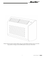
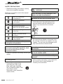
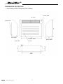
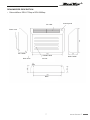
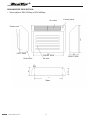
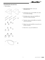
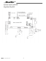
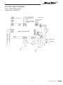
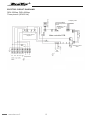
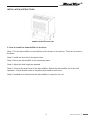
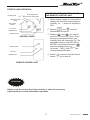
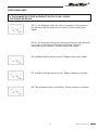
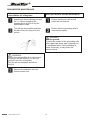
DEH-600wp, DEH-1000wp, DEH-1700wp, DEH-2000wp, DEH-2500wp, DEH-4000wp. Dehumidifiers Operation manual R Please read this manual carefully before using your dehumidifier and keep it well. If you have any question of using your dehumidifier please contact your local dealer. 1 www.danvex.fi R CONTENT Introduction................................................................................................................................3 Safety precautions.....................................................................................................................4 Dehumidifier description............................................................................................................6 Electric circuit diagrams...........................................................................................................10 Installation instructions............................................................................................................13 Start-up and operation.............................................................................................................15 Error messages.......................................................................................................................16 Denumidifier maintenance.......................................................................................................18 Technical specifications...........................................................................................................19 Warranty obligations................................................................................................................20 www.danvex.fi 2 R INTRODUCTION MODELS: DEH-600wp DEH-1000wp DEH-1700wp DEH-2000wp DEH-2500wp DEH-4000wp All the dehumidifiers described in this manual are designed to adjust the indoor relative humidity from 40% RH to 99 % RH at the ambient temperature from +1O°C up to +32°C. 3 www.danvex.fi R SAFETY PRECAUTIONS Read these safety precautions carefully WARNING before the humidifier operation. Meanings of symbols used in this manual are shown below. Don't do it under any circumstances Follow the instruction by all means There should be no any damages in the power cord and its extensions. Remove any dirt from the power cord. If dirt adheres to the power plug or the plug connection with the socket is nontight, it may cause the fire or electric shock. Be sure to ground Disconnect the power cable from the electric mains. Never put anything on the unit Danger of electric shock, be careful Never insert fingers or any objects Do not scratch or overbend the power cord. Do not put heavy objects on the power cord, do not heat it and do not expose it to any impacts. The cord may be damaged and it may cause the fire or electric shock. Do not disconnect/connect the power during the unit operation. When an abnormality (smell of burning. etc) occurs during the operation, stop the unit and disconnect it from the electric mains. If the unit operates abnormally consult your Consult your dealer for the unit installation. Do not insert your fingers or any objects in the air inlet/air outlet. dealer. Do not repair or reinstall of the unit by yourself. Use the ground. If this is done incorrectly, it may cause the fire, electric shock, water leakage, etc. Prevent the contact of the Contact your local dealer. grounding wire with a gas pipe, water pipe, lightning rod or telephone cable. If the grounding is made incorrectly, it may cause the electric shock. www.danvex.fi 4 R SAFETY PRECAUTIONS WARNING Do not pull the power cord. It can cause the short circuit and lead the Do not apply an insecticide or flammable spray. It may cause the fire or deformation of the electric shock or fire. Prior to the unit cleaning it should be switched. Disconnect the power cord from the electric mains. housing. Do not clean the unit with water. It may cause the electric shock. Since the fan rotates at high speed during operation, the cleaning of the operating unit may cause an injury. If the unit is installed in the wet place, provide its insulation against the moisture ingress. If the insulation against the moisture ingress isn't provided, it may cause the electric shock. When the unit is not going to be used for a long time, disconnect it from the electric mains. If not to do it, the dirt may collect in the unit and cause the fire. Do not install the unit where its operation is not safe. Do not install the unit where there is flammable gas. Don't try to install the unit by yourself. If this is done incorrectly, it may cause the Do not operate switches with wet hands. fire, electric shock, water leakage, etc. Contact your local dealer. It may cause the electric shock. 5 www.danvex.fi R DEHUMIDIFIER DESCRIPTION Dehumidifiers: DEH-600wp and DEH-1000wp Control panel Air outlet Power cord LEFT SIDE FRONT SIDE Drain hose Air inlet Base www.danvex.fi 6 RIGHT SIDE R DEHUMIDIFIER DESCRIPTION Dehumidifiers: DEH-1700wp и DEH-2000wp Air outlet Control panel Power cord LEFT SIDE FRONT SIDE Drain hose RIGHT SIDE Air inlet Base 7 www.danvex.fi R DEHUMIDIFIER DESCRIPTION Dehumidifiers: DEH-2500wp и DEH-4000wp Control panel Air outlet Power cord LEFT SIDE FRONT SIDE Drain hose Air inlet Base www.danvex.fi 8 RIGHT SIDE R DEHUMIDIFIER DESCRIPTION Dehumidifiers: 1. Wall mounting bracket, 2 pcs. per dehumidifier set. 2. Anchor bolt, 6 pcs. per humidifier set (used for unit wall mounting). 3. Mounting screw, 4 pcs. per humidifier set (used for unit wall mounting). 4. Floor foot, 4 pcs. per humidifier set (used for unit floor mounting). 5. Wheel, 4 pc. per humidifier set (used for unit mobile mounting). 6. Drain hose, 1 pc. per humidifier set. 9 www.danvex.fi R ELECTRIC CIRCUIT DIAGRAMS DEH-600wp, DEH-1000wp Single phase (1PH/5o Hz) Humidity sensor Internal temperature sensor To display PCB External temperature sensor Transformer Main controller PCB High pressure protection Low pressure protection Power supply Fan motor Compressor www.danvex.fi 10 R ELECTRIC CIRCUIT DIAGRAMS DEH-1700wp, DEH-2000wp Single phase (1PH/50 Hz) Humidity sensor To display PCB Internal temperature sensor External temperature sensor Transformer Main controller PCB High pressure protection Low pressure protection Power supply Fan motor Pressure control valve Compressor 11 www.danvex.fi R ELECTRIC CIRCUIT DIAGRAMS DEH-2500wp, DEH-4000wp Three phases (3PH/50 Hz) Humidity sensor Internal temperature sensor External temperature sensor Main controller PCB Transformer Low pressure protection High pressure protection PCB protection phases sequence To display PCB Pressure control valve Fan motor Red Black White Gray Green Compressor www.danvex.fi 12 R INSTALLATION INSTRUCTIONS WHEELS INSTALLATION 2. How to install the dehumidifier on the floor: Step 1: Put the dehumidifier on the platform as it's shown on the picture. There are 4 holes on the base. Step 2: Install the floor feet in the base holes. Step 3: Move the dehumidifier to the necessary place. Step 4: Adjust the feet height as required. Step 5: Connect the drain hose to the dehumidifier. Switch the dehumidifier on for the trial operation. Check whether there is any abnormal vibration and noise. Step 6: Installation is finished and the dehumidifier is ready for the use. 13 www.danvex.fi R INSTALLATION INSTRUCTIONS WHEELS INSTALLATION 3. How to install the dehumidifier on the wall: Step 1: Choose the right installation position for the wall mounting according to the size of mounting holes and position of the wall bracket holes. The installation position should guarantee the dehumidifier horizontal position. Drilling places should be marked. Step 2: Use the percussive drilling machines to drill holes with 8 cm±0.5cm depth. Then take the nuts and gaskets of the anchor bolts and install them into the holes with the hammer. Step 3: Install the wall bracket with the anchor bolts on the right position. Please take care to fix the bracket well with the nuts and gaskets. And don't forget to keep the bracket in the right direction during the installation. Step 4: Mount the dehumidifier on the wall bracket and locate it in such a way that the holes in the dehumidifier base are aligned with the bracket holes. Fix the dehumidifier on the bracket with the fixing screws and gaskets. Step 5: Connect the drain hose to the dehumidifier. Switch the dehumidifier on for the trial operation. Check whether there is any abnormal vibration and noise. Step 6: Installation is finished and the dehumidifier is ready for the use. www.danvex.fi 14 R STARTUP AND OPERATION Fault signal lamp Humidity level Electric heater signal lamp FUNCTIONS OF THE CONTROL PANEL AND REMOTE CONTROL UNIT 1. When electric supply is connected the display will show the current ambient humidity. i/ e. = indoor air humidity is 60%. Defrosting signal lamp RCU signal receiver UP button 2. Buttons and turn the dehumidifier on and off. DOWN button ON/OFF button 3. Buttons and are used to set the desired humidity level. Every time you press these buttons, the humidity level will change by 5%. The adjustable range is from 25% RH to 80%RH. If you press the button when the display shows , it will be shown --%RH , that means the nonstop dehumidification. CONTROL PANEL ON/OFF button UP button 4. Button is used to turn the electric heater (option) on and off. DOWN button REMOTE CONTROL UNIT ATTENTION! Please study the control functions carefully or make the necessary adjustments prior to the dehumidifier operation. 15 www.danvex.fi R ERROR MESSAGES IF THE HUMIDIFIED STOPS WORKING THE DIPLAY WILL SHOW THE ERROR MESSAGE E0: The defrosting system is not working correctly. Please contact your dealer. E1: The dehumidifying sensor is not working correctly. Please contact your dealer. E2: The external temperature sensor is not working correctly. Please contact your dealer. E3: Ambient temperature is over the working temperature. If the ambient temperature is over 32°C or below 10°C, it will display error message E3 too. Please contact your dealer. E4: The defrosting temperature sensor is not working correctly. Please contact your dealer. www.danvex.fi 16 R ERROR MESSAGES IF THE HUMIDIFIED STOPS WORKING THE DIPLAY WILL SHOW THE ERROR MESSAGE E5 (1): It is displayed when the unit is connected to the power for the first time and the phase error is found. Please contact your dealer. E5 (2): It is displayed during the running process and indicates that the current is exceeded or the phase is lacking. Clean the evaporator and condenser. Please contact your dealer. E6: Indicates the low pressure level. Please contact your dealer. E7: Indicates the high pressure level. Please contact your dealer. E8: The refrigerant level is insufficient. Please contact your dealer. 17 www.danvex.fi R DEHUMIDIFIER MAINTENANCE When you are going not to use the dehumidifier for a long time. When you want to use the dehumidifier. Start the air dehumidifying process for 3 – 4 hours installing the humidity level at 80% to dry the dehumidifier inside. Ensure that the air inlet and air outlet are not blocked. Turn off the dehumidifier and then the disconnect the plug from the socket. Ensure that the grounding wire is connected properly. WARNING Use the ground. Prevent the contact of the grounding wire with a gas pipe, water pipe, lightning rod or telephone cable. If the grounding is made incorrectly, it may cause the electric shock. WARNING Switch the dehumidifier off or disconnect the plug from the socket if you are not going to use it fro a long time. Dirt can be accumulated and cause the fire. Remove the batteries from the remote control unit. www.danvex.fi 18 R TECHNICAL SPECIFICATIONS NOTE: 1. Rated noise value is detected in the laboratory. 2. In case of the difference of the specifications indicated in the above table and the specifications indicated directly on the nameplate it's necessary to use the specifications of the nameplate. 3. Test data: ambient temperature is 30oC, and the ambient humidity is 80%RH. SPECIAL INSTRUCTIONS: 1. Customer should contact the special service department for the qualified installation and repair. 2. If any flexible cable is damaged, contact the special service department to replace it with the original cable. 19 www.danvex.fi R Warranty obligations DanVex warrants that all the equipment parts will answer the technical requirements for 12 months from the date of delivery (warranty period). The warranty does not cover wearable parts such as filters. The warranty covers the defects in workmanship and materials. During the warranty period DanVex repairs and replaces the part having a defect of material or an manufacturing error. DanVex completely fulfills its warranty obligations when it supplies the Customer a repaired or a spare part. Parts repair or replacement does not result in the warranty period extension. The parts and components replaced under the warranty belong to DanVex. DanVex or its distributor upon DanVex request has a right to inspect the defective parts and to check the correctness of the warranty claim. Warranty repair execution conditions: The damage occurred during the equipment normal operation. All recommendations and instructions of the manufacturer concerning the equipment installation, operation and maintenance were observed. Only original parts and materials were used for the equipment maintenance and repair. www.danvex.fi 20