1
United Kingdom
en
Installation and Service Manual
Wall Mounted Gas Condensing Boiler
Baxi MainEco Combi and System
24-28-35 / 18-24
These instructions include the Benchmark Commissioning Checklist and should be left with the
user for safe keeping. They must be read in conjunction with the Flue Installation Guide.
Dear customer,
Thank you for purchasing this appliance.
Please read this manual carefully before using the product and keep it in a safe place for future reference.
In order to ensure continued safe and efficient operation we recommend that the product is regularly maintained. Our Service
and After Sales organization can assist with this.
We hope you will receive many years of satisfactory service.
Contents
2
1.1
Building Regulations and the Benchmark
Commissioning Checklist ....................................6
1.2
The Benchmark Scheme ......................................6
1.3
Installer Notification Guidelines ..........................7
Introduction ................................................................................................8
2.1
Symbols used .......................................................8
2.2
Abbreviations ........................................................8
2.3
General ..................................................................8
2.3.1
2.3.2
2.3.3
2.4
Homologations ....................................................10
2.4.1
2.4.2
3
4
Manufacturer’s liability .............................................8
Installer’s liability .....................................................9
User’s liability ..........................................................9
Certifications .........................................................10
Additional Directives ..............................................10
Safety instructions and recommendations ............................................11
3.1
Safety instructions .............................................11
3.2
Recommendations ..............................................11
Technical description ..............................................................................13
4.1
General description ............................................13
4.2
Main parts ............................................................13
4.3
Skeleton Diagrams .............................................14
4.4
Operating principle .............................................14
4.4.1
4.4.2
4.4.3
4.4.4
4.4.5
4.4.6
4.4.7
4.4.8
02092014 - 7619497-02
Gas/air setting .......................................................14
Combustion ...........................................................15
Heating and domestic hot water production ..........15
Control system ......................................................15
Adjustment ............................................................15
Regulation of the water temperature .....................16
Protection against low water or no
circulation ..............................................................16
Overheat temperature protection ..........................16
1
Contents
5
4.5
Circulating pump (Available pump head) .........16
4.6
Technical specifications ....................................17
Installation ................................................................................................19
5.1
Regulations governing installation ...................19
5.2
Choice of the location ........................................20
5.2.1
5.2.2
Type plate .............................................................20
Location of the boiler .............................................20
5.3
Main dimensions .................................................22
5.4
Positioning the boiler .........................................23
5.5
Hydraulic connections .......................................23
5.5.1
5.5.2
5.5.3
5.5.4
5.5.5
5.5.6
5.5.7
5.5.8
Flushing the system ..............................................24
Water flow rate ......................................................24
Connection of the heating circuit ...........................24
Connection of the water circuit for domestic
use ........................................................................25
Connecting the expansion vessel .........................25
Connecting the safety valve discharge pipe ..........26
Connecting the condensate discharge pipe ..........26
Automatic air bleed ...............................................28
5.6
Gas connection ...................................................29
5.7
Connections for the air and exhaust
pipes ....................................................................29
5.7.1
5.7.2
5.7.3
5.7.4
5.7.5
5.8
Electrical connections ........................................32
5.8.1
5.8.2
5.8.3
5.8.4
5.9
Classification .........................................................29
Outlets ...................................................................30
Lengths of the air/flue gas pipes ...........................31
Additional Directives ..............................................32
Connection of the combustion gas exhaust
pipe .......................................................................32
Control unit ............................................................32
Recommendations ................................................33
Access to the connector block / Boiler HMI ...........34
Connection options ...............................................34
Electrical diagram ...............................................38
5.10 Filling the system ...............................................38
5.10.1
5.10.2
5.10.3
5.10.4
02092014 - 7619497-02
Water treatment ....................................................38
Filling the condensate trap ....................................39
Filling the system ..................................................40
Venting the system ................................................41
2
6
Commissioning ........................................................................................42
6.1
Control panel .......................................................42
6.2
Check points before commissioning ................43
6.2.1
6.2.2
6.2.3
6.3
Commissioning the boiler ..................................43
6.4
Gas settings ........................................................45
6.4.1
6.4.2
6.4.3
7
8
Preparing the boiler for commissioning .................43
Hydraulic circuit .....................................................43
Electrical connections ...........................................43
Gas circuit .............................................................45
Checking combustion ............................................45
Setting the air/gas ratio .........................................48
6.5
Finalizing work ....................................................49
6.6
Parameter descriptions ......................................50
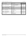
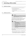
Switching off the boiler ............................................................................52
7.1
Installation shutdown .........................................52
7.2
Antifreeze protection ..........................................52
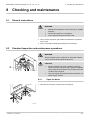
Checking and maintenance .....................................................................53
8.1
General instructions ...........................................53
8.2
Standard inspection and maintenance
operations ...........................................................53
8.2.1
8.2.2
8.2.3
8.2.4
8.2.5
8.2.6
8.2.7
8.2.8
8.2.9
8.2.10
8.3
Specific maintenance operations ......................58
8.3.1
8.3.2
8.3.3
8.3.4
8.3.5
8.3.6
02092014 - 7619497-02
Open the boiler ......................................................53
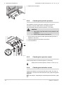
Checking the hydraulic pressure ...........................54
Checking the expansion vessel .............................54
Checking the ionization current .............................54
Checking the DHW transfer capacity ....................55
Checking the flue gas discharge and the air
supply ....................................................................55
Checking combustion ............................................55
Checking the automatic air vent ............................55
Checking the condensate trap ..............................56
Checking the burner and cleaning the heat
exchanger .............................................................57
Replacing the ionization/ignition electrode ............58
Replacing the 3-way valve ....................................59
Cleaning the plate heat exchanger .......................59
Cleaning the domestic water cartridge ..................60
Replacement of the expansion vessel ..................60
Re-assembling the boiler ......................................61
3
Contents
9
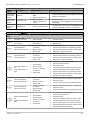
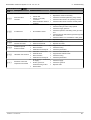
Troubleshooting .......................................................................................63
9.1
Error codes ..........................................................63
9.2
Shutdowns and lock-outs ..................................63
9.2.1
9.2.2
10
Blocking .................................................................63
Lock out .................................................................65
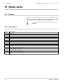
Spare parts ................................................................................................70
10.1 General ................................................................70
10.2 Spare parts ..........................................................70
11
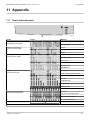
Appendix ...................................................................................................71
11.1 User instruction card ..........................................71
11.2 Gas boiler system commissioning
checklist ..............................................................72
11.3 Service record .....................................................73
02092014 - 7619497-02
4
EC declaration of conformity
The device complies with the standard type described in the EG
declaration of conformity. It was manufactured and commissioned in
accordance with European directives.
The original declaration of conformity is available from the
manufacturer.
02092014 - 7619497-02
5
Baxi MainEco Combi and System 24 - 28 - 35 / 18 - 24
1.1
Building Regulations and the Benchmark Commissioning Checklist
Building Regulations (England & Wales) require
notification of the installation of a heating appliance to the
relevant Local Authority Building Control Department.
This can be achieved via a Competent Persons Self
Certification Scheme as an option to notifying the Local
Authority directly.
The Health & Safety Executive operates the ’Gas Safe
Register’, a selfcertification scheme for gas heating
appliances.
This company is a member of the Benchmark initiative
and fully supports the aims of the programme. Its aim is
to improve the standards of installation and
commissioning of central heating systems in the UK and
to encourage the regular servicing of all central heating
systems to ensure safety and efficiency.
Building Regulations require that installations should
comply with manufacturer’s instructions. It is therefore
important that the commissioning checklist is completed
by the installer. The relevant section of Building
Regulations only relates to dwellings. Therefore the
checklist only applies if the appliance is being installed in
a dwelling or some related structure.
The flowchart opposite gives guidance for installers on the
process necessary to ensure compliance with Building
Regulations.
1.2
The Benchmark Scheme
R000725-A
Benchmark places responsibilities on both manufacturers
and installers. The purpose is to ensure that customers
are provided with the correct equipment for their needs,
that it is installed, commissioned and serviced in
accordance with the manufacturer’s instructions by
competent persons and that it meets the requirements of
the appropriate Building Regulations. The Benchmark
Checklist can be used to demonstrate compliance with
Building Regulations and should be provided to the
customer for future reference.
Installers are required to carry out installation,
commissioning and servicing work in accordance with the
Benchmark Code of Practice which is available from the
Heating and Hotwater Industry Council who manage and
promote the Scheme. Visit www.centralheating.co.uk
for more information.
6
02092014 - 7619497-02
Baxi MainEco Combi and System 24 - 28 - 35 / 18 - 24
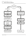
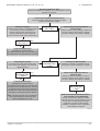
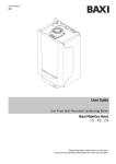
1.3
Installer Notification Guidelines
Choose Building
Regulations Notification
Route
Competent Person's
Self Certification Scheme
Building Control
Install and Commission this
appliance to manufacturer's
instructions
Contact your relevant Local
Authority Building Control
(LABC) who will arrange
an inspection or contact
a government approved
inspector
Complete the
Benchmark Checklist
If you notify via the ‘Gas Safe
Register’, the register will issue
the Building Regulations
certificate on members’ behalf
Install and Commission this
appliance to manufacturer's
instructions
Scheme Members only
Call ‘Gas Safe Register’ on:
0800 408 5577
or log onto:
www.gassaferegister.co.uk
within 10 days
Complete the
Benchmark Checklist
You must ensure that the
certificate number issued by
the ‘Gas Safe Register’ is written
onto the Benchmark Checklist
‘Gas Safe Register’ will issue a
Building Regulations Compliance
Certificate to the property owner
and inform the relevant LABC
LABC will record the data
and will issue a
certificate of compliance
R000696-01
02092014 - 7619497-02
7
2. Introduction
2
Introduction
2.1
Symbols used
Baxi MainEco Combi and System 24 - 28 - 35 / 18 - 24
In these instructions, various danger levels are employed to draw the
user’s attention to particular information. In so doing, we wish to
safeguard the user’s safety, highlight hazards and guarantee correct
operation of the appliance.
DANGER
Risk of a dangerous situation causing serious physical
injury.
WARNING
Risk of a dangerous situation causing slight physical
injury.
CAUTION
Risk of material damage.
Signals important information.
¼Signals a referral to other instructions or other pages in the
instructions.
2.2
Abbreviations
4 LTH: Low temperature heating
4 DHW: Domestic hot water
4 HRU: Heat Recovery Unit
4 PCU: Primary Control Unit - Electronic system to control burner
function
4 SCU: Secondary Control Unit - Additional electronic system
2.3
General
2.3.1.
Manufacturer’s liability
Our products are manufactured in compliance with the requirements
of the various applicable European Directives. They are therefore
delivered with [ marking and all relevant documentation.
8
02092014 - 7619497-02
Baxi MainEco Combi and System 24 - 28 - 35 / 18 - 24
2. Introduction
In the interest of customers, we are continuously endeavouring to
make improvements in product quality. All the specifications stated in
this document are therefore subject to change without notice.
Our liability as the manufacturer may not be invoked in the following
cases:
4 Failure to abide by the instructions on using the appliance.
4 Faulty or insufficient maintenance of the appliance.
4 Failure to abide by the instructions on installing the appliance.
2.3.2.
Installer’s liability
The installer is responsible for the installation and commissioning of
the appliance. The installer must respect the following instructions:
4 Read and follow the instructions given in the manuals provided
with the appliance.
4 Carry out installation in compliance with the prevailing legislation
and standards.
4 Perform the initial start up and carry out any checks necessary.
4 Explain the installation to the user.
4 If a maintenance is necessary, warn the user of the obligation to
check the appliance and maintain it in good working order.
4 Give all the instruction manuals to the user.
2.3.3.
User’s liability
To guarantee optimum operation of the appliance, the user must
respect the following instructions:
4 Read and follow the instructions given in the manuals provided
with the appliance.
4 Call on qualified professionals to carry out installation and initial
start up.
4 Get your installer to explain your installation to you.
4 Ensure the Appliance is serviced in accordance with the
manufacturer’s instructions by a suitable qualified person.
4 Keep the instruction manuals in good condition close to the
appliance.
This appliance is not intended to be used by persons (including
children) whose physcial, sensory or mental capacity is impaired or
persons with no experience or knowledge, unless they have the
benefit, through the intermediary of a person responsible for their
safety, of supervision or prior instructions regarding use of the
appliance. Care should be taken to ensure that children do not play
with the appliance.
If the mains power lead is damaged it must be replaced by the original
manufacturer, the manufacturer’s dealer or another competent
person to prevent hazardous situations.
02092014 - 7619497-02
9
2. Introduction
2.4
Baxi MainEco Combi and System 24 - 28 - 35 / 18 - 24
Homologations
2.4.1.
Certifications
CE identification no
PIN 0063CM3019
NOx classification
5 (Standards EN)
Type of connection (Flue gas outlet) C13, C33, C53
Gas Council number
2.4.2.
MainEco Combi 24: 47–075–93
MainEco Combi 28: 47–075–94
MainEco Combi 35: 47–075–95
MainEco System 18: 41–470–13
MainEco System 24: 41–470–14
Additional Directives
Apart from the legal provisions and Directives, the additional
Directives described in these instructions must also be observed.
For all provisions and Directives referred to in these instructions, it is
agreed that all addenda or subsequent provisions will apply at the
time of installation.
10
02092014 - 7619497-02
Baxi MainEco Combi and System 24 - 28 - 35 / 18 - 24
3. Safety instructions and recommendations
3
Safety instructions and
recommendations
3.1
Safety instructions
DANGER
If you smell gas:
1.
2.
3.
4.
5.
6.
Do not use a naked flame, do not smoke, do not
operate electrical contacts or switches ( doorbell,
light, motor, lift, etc..).
Shut off the gas supply.
Open the windows.
Report any leaks immediately.
Trace possible leaks and seal them immediately.
If the gas leak is before the gas meter, contact the
gas supplier.
DANGER
If you smell flue gases:
1.
2.
3.
4.
3.2
Switch the appliance off.
Open the windows.
Report any leaks immediately.
Trace possible leaks and seal them immediately.
Recommendations
WARNING
4
4
4
Installation and maintenance of the boiler must be
carried out by a qualified professional in compliance
with prevailing local and national regulations.
When working on the boiler, always disconnect the
boiler from the mains and close the main gas inlet
valve.
After maintenance or repair work, check all
installations to ensure that there are no leaks.
CAUTION
The boiler must be installed in a frost-free environment.
Keep this document close to the place where the boiler is
installed.
02092014 - 7619497-02
11
3. Safety instructions and recommendations
Baxi MainEco Combi and System 24 - 28 - 35 / 18 - 24
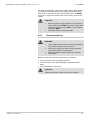
Casing components
Only remove the casing for maintenance and repair operations. Put
the casing back in place after maintenance and repair operations.
Instructions stickers
The instructions and warnings affixed to the appliance must never be
removed or covered and must remain legible during the entire lifespan
of the appliance. Immediately replace damaged or illegible
instructions and warning stickers.
Modifications
Modifications may only be made to the boiler after the written
permission of BAXI to do so.
12
02092014 - 7619497-02
Baxi MainEco Combi and System 24 - 28 - 35 / 18 - 24
4. Technical description
4
Technical description
4.1
General description
Wall-hung gas condensing boilers
4 High efficiency heating.
4 Low pollutant emissions.
4 Installation and connection facilitated by the mounting frame
delivered with the appliance.
4 Flue gas discharge via a forced flue or chimney type connection.
4 Baxi MainEco Combi 24 - 28 - 35: Heating and domestic hot
water production.
4 Baxi MainEco System 18 - 24: Heating only.
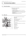
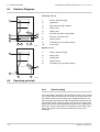
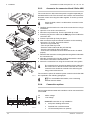
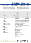
4.2
Main parts
2
1
Flue gas outlet/Air intake (Combustion air/flue gas
adapter 60/100)
2
Casing/air box
3
Outlet for measuring combustion gases
4
Ignition/ionization electrode
5
Flue gas discharge pipe
6
Gas/air system with a fan, gas block and automatic burner
unit
7
Air intake silencer
8
Plate heat exchanger (DHW) (Only for Combi models)
9
Connection box
10
Condensate trap
11
11
Circulation pump
10
12
3-way valve
13
Primary heat exchanger
14
Expansion vessel
15
Automatic air vent
1
3
15
4
5
14
6
7
13
12
8
9
T004783-A
02092014 - 7619497-02
13
4. Technical description
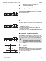
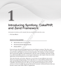
4.3
Baxi MainEco Combi and System 24 - 28 - 35 / 18 - 24
Skeleton Diagrams
Combi 24 - 28 - 35
1
Primary heat exchanger
2
Hydroblock
3
Plate heat exchanger (DHW)
4
Safety valve
5
Heating flow
9
6
Domestic hot water outlet (DHW)
10
7
Domestic cold water inlet
8
Heating return
9
Circulation pump (Central heating)
10
3-way valve
1
2
3
4
5
6
7
8
T003393-D
System 18 - 24
1
1
Primary heat exchanger
2
Safety valve
3
Heating flow
4
Heating return
5
Circulation pump (Central heating)
5
2
3
4
T003807-A
4.4
Operating principle
4.4.1.
Gas/air setting
The casing fitted to the boiler is also used as an air box. Air is sucked
in by the fan and gas injected into the venturi by the fan intake. The
fan rotation speed is set according to the settings parameters, the
thermal energy requirement and the temperatures measured by the
temperature sensors. The gas and air are mixed in the venturi. The
gas/air ratio ensures that the quantities of gas and air are adjusted to
each other. This provides optimum combustion on the entire output
range. The gas/air mixture is fed into the burner on top of the
exchanger.
14
02092014 - 7619497-02
Baxi MainEco Combi and System 24 - 28 - 35 / 18 - 24
4.4.2.
4. Technical description
Combustion
The burner heats the heating water circulating in the heat
exchanger. At a return temperature lower than around 55°C, the flue
gases cool down to a temperature lower than the dew point, thus
causing the condensation of the water vapour contained in the flue
gases in the lower section of the heat exchanger. The heat released
during this condensation process (the latent heat or condensing heat)
is also transferred to the heating water. The cooled combustion gases
are evacuated via the combustion gas outlet flue. The condensation
water is evacuated via a condensate trap.
4.4.3.
Heating and domestic hot water production
On combi boilers, an integrated plate exchanger heats the domestic
water. A 3-way valve determines whether the heated water is fed into
the heating system or the plate exchanger. A pick-up sensor signals
that a hot water tap is being opened. This signal is transmitted to the
control panel, which then switches the 3-way valve to the hot water
position and trips the heating pump. The 3-way valve is spring-loaded
but only consumes electricity when it switches to another position.
The heating water reheats the domestic water in the plate
exchanger. In comfort mode, if there is no hot water draw-off, the
boiler handles the periodic reheating of the plate exchanger. Any
limescale particles are kept out of the plate exchanger by a selfcleaning water filter (self-cleans once every 76 hours).
4.4.4.
Control system
Control of the boiler ensures reliable delivery of heat. This means that
the boiler treats external negative influences in a practical manner
(notably when the water-flow is insufficient or there are problems with
air supply). In the presence of such influences, the boiler doesn’t
switch into locking mode, but first reduces his power and, depending
on the nature of the circumstances, will be temporarily out of service
(blocking or stop). The boiler will continue to supply heat as long as
the situation does not become dangerous.
4.4.5.
Adjustment
The power of the boiler can be adjusted in the following ways:
4 On/Off setting
The output between the minimum and maximum values varies
based on the heating flow set point temperature.
4 Adjustable control
The output between the minimum and maximum values varies
based on the heating flow temperature determined by the
modulating control system.
02092014 - 7619497-02
15
4. Technical description
Baxi MainEco Combi and System 24 - 28 - 35 / 18 - 24
4.4.6.
Regulation of the water temperature
The boiler is fitted with an electronic temperature regulator having an
outlet and return temperature probe. The flow temperature can be set
between 20°C and 90°C. The boiler reduces its power when the set
outlet-temperature is attained. The cutout temperature is the set
heating outlet-temperature + 5 °C.
4.4.7.
Protection against low water or no
circulation
The boiler is fitted with a safety device to prevent the shortage of water
based on temperature measurements. By reducing its output when
the water flow rate is in danger of becoming insufficient, the boiler
continues to operate as long as possible. In case of insufficient ΔT
≥ 50°C flow or an excessive increase in flow temperature, the boiler
will enter shutdown mode for 10 minutes. When there is no water in
the boiler, or if the pump is not running, the system is locked
(breakdown)
In the event of a fault, the status signal for the B button on
the connection box flashes red.
¼For more detailed information, see chapter: "Shutdowns and
lock-outs", page 63.
4.4.8.
Overheat temperature protection
The maximum temperature protection locks the boiler if the water
temperature becomes too high (110°C).
In the event of a fault, the status signal for the B button on
the connection box flashes red.
¼For more detailed information, see chapter: "Shutdowns and
lock-outs", page 63.
Anticycle function is active when heat demand is active and
the flow temperature is too high with respect to the
setpoint. The anticycle time can be active between 3
and 9 minutes depending on system temperatures.
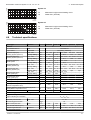
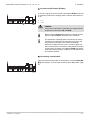
4.5
Circulating pump (Available pump head)
H (mbar)
The boiler is fitted with an on/off circulation pump.
700
600
500
2
1
400
300
30 kW
317
20 kW
253
200
100
0
0
24 kW
127
200
400
600
800
860
16
1000
1030
1200
1250
1400
1
Combi 24 - 28
2
Combi 35
H
Manometric height central heating circuit
Q
Water flow ( ΔT=20K)
1600
1500
Q (l/h)
R000684-A
02092014 - 7619497-02
H (mbar)
Baxi MainEco Combi and System 24 - 28 - 35 / 18 - 24
4. Technical description
System 18
600
500
400
300
18 kW
H
Manometric height central heating circuit
Q
Water flow ( ΔT=20K)
280
200
100
0
0
200
400
600
800
775
1000
1200
1400
1600
H (mbar)
Q (l/h)
R000685-A
System 24
600
500
400
300
20 kW
253
200
100
24 kW
127
0
0
200
400
600
800
860
4.6
1000
1030
1200
1400
H
Manometric height central heating circuit
Q
Water flow ( ΔT=20K)
1600
Q (l/h)
R000365-A
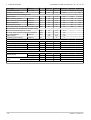
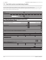
Technical specifications
Boiler type
MainEco
Combi 24
Combi 28
Combi 35
System 18 System 24
General
EC indentification no.
PIN
0063CM3019
Input control
Adjustable
Nominal output (Pn)
Heating System (80/60 °C)
min - max
kW
5.5 - 19.5
5.5 - 23.4
7.7 - 29.2
5.5 - 17.7
5.5 - 23.4
Factory setting
kW
19.5
19.5
29.2
17.7
23.4
Nominal output (Pn)
Heating System (50/30 °C)
min - max
kW
6.1 - 20.9
6.1 - 24.8
8.5 - 31.0
6.1 - 18.8
6.1 - 24.8
Factory setting
kW
20.9
20.7
31.0
18.8
24.8
Nominal output (Pn)
DHW System
min - max
kW
5.5 - 23.4
5.5 - 27.5
7.7 - 33.9
-
-
Factory setting
kW
23.4
27.5
33.9
-
-
Nominal input (Qn)
Heating System (Hi)
min - max
kW
5.6 - 20.0
5.6 - 24.0
7.8 - 30.0
5.6 - 18.0
5.6 - 24.0
Factory setting
kW
20.0
20.0
30.0
18.0
24.0
Nominal input (Qn)
Heating System (Hs)
min - max
kW
6.2 - 22.2
6.2 - 26.7
8.7 - 33.3
6.2 - 20.0
6.2 - 26.7
Factory setting
kW
22.2
22.2
33.3
20.0
26.7
Nominal input (Qnw)
DHW System (Hi)
min - max
kW
5.6 - 24.0
5.6 - 28.2
7.8 - 34.9
-
-
Factory setting
kW
24.0
28.2
34.9
-
-
Nominal input (Qnw)
DHW System (Hs)
min - max
kW
6.2 - 26.7
6.2 - 31.3
8.7 - 38.8
-
-
Factory setting
Modulating, Start/Stop
kW
26.7
31.3
38.8
-
-
Heating efficiency under full load (Hi) (80/60 °C)
%
97.6
97.6
97.2
98.2
97.6
Heating efficiency under full load (Hi) (50/30 °C)
%
104.5
103.3
103.3
104.5
103.3
Heating efficiency under partial load (Hi)
(Return temperature 60°C)
%
97.8
97.8
98.4
97.8
97.8
Heating efficiency under partial load (Hi) (92/42
EEG) (Return temperature 30°C)
%
109.2
109.2
108.8
109.3
109.2
SEDBUK
2005 - 2009
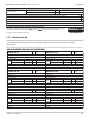
Data on the gases and combustion gases
%
90.4 - 89.4 90.3 - 89.3 90.1 - 89.1 90.4 - 89.4 90.3 - 89.3
Equipment categories
-
I2H
Type of air/flue gas connection
-
C13, C33, C53
Gas inlet pressure G20
min - max
Connecting pressure G20
Gas consumption G20
17 - 23
mbar
max
NOx annual emission (n=1)
Mass flue gas flow rate
mbar
m3/h
mg/kWh
maximum
kg/h
20
2.54
2.98
3.68
1.90
2.54
53
58
52
41
58
9.4 - 38.7
9.4 - 45.5
13.1 - 56.2
9.4 - 29.1
9.4 - 38.7
(1) Front panel removed
02092014 - 7619497-02
17
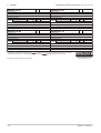
4. Technical description
Baxi MainEco Combi and System 24 - 28 - 35 / 18 - 24
Boiler type
MainEco
Flue gas temperature
min - max
Combi 24
Combi 28
Combi 35
°C
32 - 78
32 - 84
31 - 82
System 18 System 24
32 - 65
32 - 78
Maximum counter pressure
Characteristics of the heating circuit
Pa
80
116
105
-
80
Water content
l
1.6
1.6
1.7
1.4
1.4
minimum
bar
0.8
0.8
0.8
0.8
0.8
Water operating pressure (PMS) maximum
bar
2.5
2.5
2.5
2.5
2.5
Water temperature
maximum
°C
110
110
110
110
110
Operating temperature
maximum
Water operating pressure
°C
90
90
90
90
90
Manometric height central heating circuit (ΔT = 20K)
Characteristics of the domestic hot water circuit
mbar
253
127
317
280
275
Specific hot water flow Rate 35 °C Rise
l/min
9.8
11.4
14.3
-
-
Domestic water resistance (without flow restrictor)
mbar
96
123
215
-
-
Flow rate threshold
l/min
1.2
1.2
1.2
-
-
l
0.16
0.16
0.18
-
-
8
8
8
-
-
minimum
Water content
Operating pressure (Pmw)
Electrical characteristics
maximum
Power supply voltage
bar
VAC
230
230
230
230
230
Power consumption - Full load
maximum
W
105
117
145
92
103
Power consumption - Part load
maximum
W
82
82
101
82
82
Power consumption - Standby
maximum
W
3
3
3
3
3
Electrical protection index
Other characteristics
Weight (empty)
Acoustic level at 1
metre
IP
X4D
Total
kg
26
26
28.5
25
24.5
Mounting(1)
kg
24
24
27
23
23
maximum Heating System
dB(A)
38
38
42
38
40
maximum DHW System
dB(A)
40
42
45
-
-
(1) Front panel removed
18
02092014 - 7619497-02
Baxi MainEco Combi and System 24 - 28 - 35 / 18 - 24
5. Installation
5
Installation
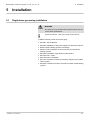
5.1
Regulations governing installation
WARNING
The engineer must be Gas Safe registered and have the
correct ACS qualifications.
Codes of Practice - refer to the most recent version.
In GB the following Codes of Practice apply:
4 BS 6891: Gas installation.
4 BS 5546: Installation of hot water supplies for domestic purposes.
4 BS EN 12828: Heating systems in buildings.
4 BS EN 14336: Installation & commissioning of water based
heating systems.
4 BS 6798: Installation of gas fired hot water boilers.
4 BS 5440 Part 1: Flues.
4 BS 5440 Part 2: Ventilation.
4 BS 7074: Expansion vessels and ancillary equipment for sealed
water systems.
4 BS 7593: Treatment of water in domestic hot water central heating
systems.
02092014 - 7619497-02
19
5. Installation
5.2
Baxi MainEco Combi and System 24 - 28 - 35 / 18 - 24
Choice of the location
5.2.1.
Type plate
The identification plate on top of the boiler features the boiler serial
number and important boiler specifications, for example the model
and unit category. The dF and dU codes are also stated on the type
plate.
R000697-A
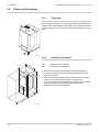
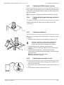
5.2.2.
5
5
36
(1)
8
5
≥2
00
55
4
Location of the boiler
(1)
Clearance when operating
(2)
Clearance for maintenance
4 Before mounting the boiler, decide on the ideal position for
mounting, bearing the Directives and the dimensions of the
appliance in mind.
4 Ensure that there is sufficient space under the boiler to fit and
remove the condensate trap and the connection box.
4 To ensure adequate accessibility to the appliance and facilitate
maintenance, leave enough space around the boiler.
4 Mount the boiler onto a flat surface.
≥2
50
36
0
10
0
4
(2)
R000698-A
20
02092014 - 7619497-02
Baxi MainEco Combi and System 24 - 28 - 35 / 18 - 24
5. Installation
When choosing the position for mounting the boiler, bear
in mind the authorised position of the combustion gas
discharge outlets and the air intake opening.
¼For more information, see chapter: "Connections for
the air and exhaust pipes", page 29.
)For more detailed information, see: Flue Accessories
& Fitting Guide.
WARNING
4
4
4
4
Fix the appliance to a solid wall capable of bearing
the weight of the appliance when full of water and fully
equipped.
Do not place the appliance above a heat source or a
cooking appliance.
Do not locate the boiler in direct sunlight.
It is forbidden to store inflammable products and
materials in the boiler room or close to the boiler,
even temporarily.
CAUTION
4
4
4
The boiler must be installed in a frost-free
environment.
An earthed electrical connection must be available
close to the boiler.
A connection to the mains drainage system for the
discharge of condensate must be available close to
the boiler.
n Safety rating
Z
1
0
2
3
OZ
Z
Zones
OZ
Breakdown of the exterior zone
B
Bathtub or shower tray
225
For safety rating IP X4D, installation in the bathroom is possible in
zones 2 and 3 and in the breakdown of the exterior zone.
In this case, connect the 230 V power supply as a fixed connection
to a fused spur.
B
60
240
T000756-A
CAUTION
In the case of a fixed connection to the power cord, you
must always install a main bipolar switch with an opening
gap of at least 3 mm (EN 60335-1).
02092014 - 7619497-02
21
5. Installation
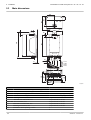
5.3
Baxi MainEco Combi and System 24 - 28 - 35 / 18 - 24
Main dimensions
243
364
90
184
541
664
76
46
368
35
52
5 (1)
1
2
1
3
2
3
4
187
209
230
4
= 117
= 184
= 251
= 316
151
R000699-B
Boiler
i
h
ê
j
{
Connection kit
Connection of the combustion gas exhaust pipe; Ø 60 mm
Connection of the air intake pipe; Ø 100 mm
Safety valve outlet pipe; Ø 15 mm
To Ø 15 mm using supplied adapter
Condensates discharge; Ø 25 mm
To Ø 21.5 mm using supplied adapter
Heating circuit flow; G¾"
Pipe diameter; Ø 22 mm
Domestic hot water outlet; G½"
y
Gas / Gaz Gas connection; G½"
x
z
(1)
22
Pipe diameter; Ø 15 mm
Pipe diameter; Ø 22 mm
Domestic cold water inlet; G½"
Pipe diameter; Ø 15 mm
Heating circuit return; G¾"
Pipe diameter; Ø 22 mm
Clearance when operating; ≥ 5 mm
02092014 - 7619497-02
Baxi MainEco Combi and System 24 - 28 - 35 / 18 - 24
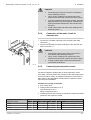
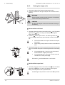
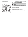
5.4
5. Installation
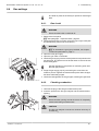
Positioning the boiler
The following components are supplied as standard with the boiler:
4 Mounting rail and mounting accessories for wall mounting
4 Connection kit comprising sleeves and clamping rings
4 Condensate trap with drain hose
4 PRV hose
4 Set rubber hose connectors and clips
4 Filling loop
4 Air/Exhaust adapter
4 Thermo-pressure gauge
4 Connection box
Please fit these components in the order described in this manual.
A suspension clamp situated at the rear of the casing enables the
boiler to be directly suspended on the mounting bracket.
CAUTION
1
During mounting, cover up the connection points for the
air supply and the combustion gas exhaust, to protect the
boiler and its connections from dust. Only remove this
protection at the time when these connections are made.
2
3
1. Determine the position of the two fixing holes. Make sure that the
holes are level. Drill 2 holes with a Ø of 8 mm.
2. Insert the rawplugs with a Ø of 8 mm. Secure with Ø 6 mm bolts
and corresponding washers.
3. Mount the boiler using the suspension bracket on the back of the
boiler.
R000409-A
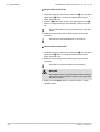
5.5
Hydraulic connections
°C
bar
≥ 250 mm
235 mm
CAUTION
When fitting pipes, remember that the condensate trap will
need to be installed and removed. Maintain at least 25 cm
distance from the boiler to allow for bends or taps to be
installed.
R000410-B
02092014 - 7619497-02
23
5. Installation
Baxi MainEco Combi and System 24 - 28 - 35 / 18 - 24
5.5.1.
Flushing the system
Installing the boiler in new installations (installations less than
6 months old)
4 Clean the installation with a universal cleaner to eliminate debris
from the system (copper, hemp, flux).
4 Thoroughly flush the installation until the water runs clear and
shows no impurities.
Installing the boiler in existing installations
4 Remove sludge from the installation.
4 Flush the installation.
4 Clean the installation with a universal cleaner to eliminate debris
from the system (copper, hemp, flux).
4 Thoroughly flush the installation until the water runs clear and
shows no impurities.
5.5.2.
Water flow rate
The boiler’s modulating control system limits the maximum difference
in temperature between the heating flow and return and the maximum
speed at which the flow temperature increases. In this way, the boiler
does not require a minimum water flow rate.
If using a heating and domestic hot water production type
boiler on an installation in which the flow can be fully
disconnected from the return (e.g. by using thermostatic
valves), you should either fit a bypass or fit an expansion
vessel to the heating flow conduit.
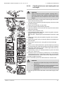
5.5.3.
1. Connect the heating water return pipe to the heating return
connection z.
2. Install a filling and drainage valve on the installation for filling and
draining the boiler.
3. Connect the heating water outlet pipe to the heating flow
connection {.
4. Mount the supplied thermomanometer onto the central heating
flow connection. Place the thermomanometer no more than 0.5 m
away from the boiler.
1
3
4
Connection of the heating circuit
A PRV safety valve is fitted to the flow side of the boiler as
standard.
2
R000737-A
24
02092014 - 7619497-02
Baxi MainEco Combi and System 24 - 28 - 35 / 18 - 24
5. Installation
CAUTION
4
4
4
4
5.5.4.
The heating pipe must be mounted in accordance
with prevailing provisions.
Carry out any soldering work required at a safe
distance from the boiler or before the boiler is fitted.
If you are installing a service shut-off valve, place the
filling and drain cock, the expansion vessel and the
thermomanometer between the shut-off valve and
the boiler.
Install a drain under the safety valve leading to the
drainage system ê.
Connection of the water circuit for
domestic use
1. Connect the cold water inlet pipe to the domestic cold water
connection k.
2. Connect the domestic hot water outlet pipe to the domestic hot
water connection m.
CAUTION
1
4
2
4
4
The domestic water pipes must be connected in
accordance with prevailing provisions.
Carry out any soldering work required at a safe
distance from the boiler or before the boiler is fitted.
If using synthetic pipes, follow the manufacturer’s
(connection) instructions.
R000738-A
5.5.5.
Connecting the expansion vessel
The boiler is fitted as standard with an 8-litre expansion vessel.
If the water volume is greater than 100 litres or the static height of the
system exceeds 5 metres, an additional expansion vessel must be
fitted. Refer to the table below to determine the expansion vessel
required for the installation.
Conditions of validity of the table:
4 3-bar safety valve
4 Average water temperature: 70 °C
Flow temperature: 80 °C
Return temperature: 60 °C
4 The filling pressure in the system is lower than or equal to the initial
pressure in the expansion vessel
Initial pressure of the
expansion vessel
Volume of the expansion vessel depending on the volume of the installation (in litres)
100
125
150
175
200
250
300
> 300
0.5 bar
4.8
6.0
7.2
8.4
9.6
12.0
14.4
Volume of the installation x 0.048
1 bar
8.0(1)
10.0
12.0
14.0
16.0
20.0
24.0
Volume of the installation x 0.080
1.5 bar
13.3
16.6
20.0
23.3
26.6
33.3
39.9
Volume of the installationx 0.133
(1) Factory configuration
02092014 - 7619497-02
25
5. Installation
Baxi MainEco Combi and System 24 - 28 - 35 / 18 - 24
5.5.6.
Connecting the safety valve discharge pipe
1. Connect the safety valve pipe to the safety valve outlet ê.
CAUTION
4
4
Any soldering must be completed before fitting the
pipework to prevent damage from heat.
Do not fit the condensate trap until the discharge pipe
has been soldered and fitted.
1
R000739-A
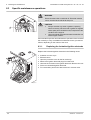
5.5.7.
Connecting the condensate discharge pipe
The condensate trap is supplied separately as standard with the
boiler (Includes flexible plastic drain hose and adapter). Fit these
parts underneath the boiler. To do this, proceed as follows:
1. Fill the condensate trap with water up to the mark.
CAUTION
Fill the condensate trap with water before starting the
boiler to avoid combustion products escaping from the
boiler.
2
2. Press the condensate trap firmly into the j opening provided for
it underneath the boiler. The condensate trap must click into place.
1
CAUTION
3
R000740-A
Check whether the condensate trap is solidly fitted in the
boiler.
3. Insert the flexible drain hose from the condensate trap into a drain
pipe.
4. Mount a trap or a siphon in the discharge pipe.
CAUTION
Do not make a permanent rigid connection owing to
maintenance work on the condensate trap.
4
Do not plug the condensate discharge pipe.
4
Do not drain condensation water into a roof gutter at
any time.
Connect the condensate discharge pipe in
accordance with prevailing standards.
4
26
02092014 - 7619497-02
Baxi MainEco Combi and System 24 - 28 - 35 / 18 - 24
5. Installation
≥ 450 (2)
Termination to an internal soil and vent pipe
≥ 2.5° (1)
(1)
Set the discharge pipe at a gradient of at least 50 mm per
metre, maximum horizontal length 5 metres.
(2)
450 mm is applicable to properties up to 3 storeys..
For multi-storey building installations consult BS 6798.
R000700-A
External termination via internal discharge branch e.g sink
waste - downstream
(1)
Set the discharge pipe at a gradient of at least 50 mm per
metre, maximum horizontal length 5 metres.
(2)
Pipe must terminate above water level but below
surrounding surface. Cut end at 45°.
≥ 2.5° (1)
It is not recommended to connect upstream of the sink or
other waste water receptacle!
(2)
R000701-A
Termination to a drain or gully
≥ 2.5° (1)
(1)
Set the discharge pipe at a gradient of at least 50 mm per
metre, maximum horizontal length 5 metres.
(2)
Pipe must terminate above water level but below
surrounding surface. Cut end at 45°.
(2)
R000702-A
Termination to a purpose made soakaway
≥ 500
≥ 2.5° (1)
(1)
Set the discharge pipe at a gradient of at least 50 mm per
metre, maximum horizontal length 5 metres.
(2)
Holes in the soak-away must face away from the building.
Further specific requirements for soakaway design are
referred to in BS 6798.
(2)
R000703-A
02092014 - 7619497-02
27
5. Installation
Baxi MainEco Combi and System 24 - 28 - 35 / 18 - 24
Pumped into an internal discharge branch (e.g. sink waste)
downstream of the trap
≥ 2.5° (1)
(2)
A
A
Basement or similar (heated).
(1)
Set the discharge pipe at a gradient of at least 50 mm per
metre, maximum horizontal length 5 metres.
(2)
Pipe must terminate above water level but below
surrounding surface. Cut end at 45°.
(3)
Condensate pump.
(3)
R000704-A
≥ 2.5°
Pumped into an external soil & vent pipe
(1)
B
A
Basement or similar (heated).
B
Unheated location (e.g. garage).
(1)
Set the discharge pipe at a gradient of at least 50 mm per
metre, maximum horizontal length 5 metres.
(2)
Condensate pump.
A
(2)
R000705-A
To a drain or gully with extended external run & trace heating
≥ 2.5° (1)
(1)
Set the discharge pipe at a gradient of at least 50 mm per
metre, maximum horizontal length 5 metres.
(2)
Pipe must terminate above water level but below
surrounding surface. Cut end at 45°.
The ’Trace Heating’ element must be installed in
accordance with the instructions supplied. External runs &
those in unheated locations still require insulation.
(2)
R000706-A
5.5.8.
Automatic air bleed
Check that the automatic bleed valve is open: This is visible on the
right on top of the boiler. If necessary, the air vent can be closed off
with the cap that can be found next to it.
R000350-A
28
02092014 - 7619497-02
Baxi MainEco Combi and System 24 - 28 - 35 / 18 - 24
5.6
5. Installation
Gas connection
1. Connect the gas inlet pipe GAS / GAZ.
The pipe must have a diameter of at least 22 mm.
WARNING
Close the main gas valve before starting work on the
gas pipes.
Before mounting, check that the gas meter has
sufficient capacity. To do this, you should keep in
mind the consumption of all domestic appliances.
If the gas meter has a too low capacity, inform the
energy supply company.
4
4
R000735-A
4
CAUTION
Connect the gas pipe in accordance with prevailing
standards and regulations.
Carry out any soldering work required at a safe
distance from the boiler or before the boiler is fitted.
Ensure that there is no dust in the gas pipe. Blow into
the pipe or shake it before mounting.
4
4
4
5.7
Connections for the air and exhaust pipes
Only use approved flue gas discharge and air supply
materials supplied by BAXI.
)For more detailed information, see: Flue Accessories
& Fitting Guide.
5.7.1.
Classification
The table specifies this classification in detail according to [.
Type Execution
C13
Description
Room sealed 4
4
C33
Room sealed 4
4
C53
Room sealed 4
Vent in the outside wall.
The opening for the air-supply inlet is located in the same pressure zone as the vent (For example, a
common passage through the outside wall).
Exhaust of combustion gases above the roof.
The opening for the air-supply inlet is located in the same pressure zone as the vent (For example, a
concentric passage to the roof).
Closed equipment.
4
Separate channelling for the air-supply.
4
Separate channelling for the combustion gases.
4
Terminating on different pressure surfaces.
02092014 - 7619497-02
29
5. Installation
Baxi MainEco Combi and System 24 - 28 - 35 / 18 - 24
5.7.2.
Outlets
When codes of practice dictate the use of a terminal guard
use a suitable guard of stainless steel construction. There
must be a clearance of at least 50 mm between any part of
the terminal and the guard.
T
J,K
U
N
R
M
I
D
E
C
I
A
I
F
S
I
F
J,K
B
L
A
A
G
H
H
I
Likely flue positions requiring a flue terminal guard
R000707-A
Terminal position with minimum distance
A(1)
Directly below an opening, air brick, opening windows, etc.
300 mm
B(1)
Above an opening, air brick, opening window etc.
300 mm
C(1)
Horizontally to an opening, air brick, opening window etc.
300 mm
D(2)
Below gutters, soil pipes or drain pipes.
E(2)
Below eaves.
25 (200) mm
F(2)
Below balconies or car port roof.
25 (200) mm
G(2)
From a vertical drain pipe or soil pipe.
25 (150) mm
H(2)
From an internal or external corner.
25 (300) mm
I
Above ground, roof or balcony level.
J
From a surface or boundary line facing a terminal.
600 mm
K
From a terminal facing a terminal (Horizontal flue).
From a terminal facing a terminal (Vertical flue).
1200 mm
600 mm
L
From an opening in carport (e.g. door, window) into the dwelling.
1200 mm
M
Vertically from a terminal on the same wall.
1500 mm
N
Horizontally from a terminal on the same wall.
300 mm
R
From adjacent wall to flue (vertical only).
300 mm
S
From an adjacent opening window (vertical only).
T
Adjacent to windows or openings on pitched and flat roofs.
U
Below windows or openings on pitched roofs.
25 (75) mm
300 mm
1000 mm
600 mm
2000 mm
(1) In addition, the terminal should be no nearer than 150 mm to an opening in the building fabric formed for the purpose of accommodating a
built-in element such as a window frame.
(2) Only one 25 mm clearance is allowed per installation. If one of the dimensions D, E, F, G or H is 25 mm then the remainder MUST be as
shown in brackets, in accordance with BS 5440-1
30
02092014 - 7619497-02
Baxi MainEco Combi and System 24 - 28 - 35 / 18 - 24
5. Installation
5.7.3.
Lengths of the air/flue gas pipes
To define the maximum final length, you must deduct the
pipe length in accordance with the reduction table.
n Room sealed flue
Concentric
If using a room sealed version, both the combustion gas exhaust
opening and the air supply opening must be connected
(concentrically). Refer to the table to determine the maximum pipe
length of the flue gas pipes in room sealed operation.
L=
Maximum chimney length for room sealed operation
Diameter
Combi 24 Combi 28 Combi 35 System 18 System 24
60-100 mm
R000415-A
80-125 mm
9m
12
m(1)
9m
12
5m
m(1)
12
m(1)
9m
12
m(1)
9m
12 m(1)
(1) With retention of the maximum chimney length it is possible to apply an extra
10 times 45° or 5 times 90° elbows
Eccentric
An 80/80 mm flue gas adapter (accessory) must be fitted
for this connection.
L=
If using a room sealed version, it is necessary to connect both the
combustion gas exhaust and the air-supply opening (parallel). The
pipes must be run in parallel and terminate in the same pressure zone
using the concentric vertical terminal.
Maximum chimney length for room sealed operation
R000719-A
Diameter
80-80 mm
Combi 24 Combi 28 Combi 35 System 18 System 24
15 m
15 m
15 m
15 m
15 m
n Reduction table
Pipe reductions per element used
Diameter
Elbow 45°
Elbow 90°
Pipe reduction Pipe reduction
60-100 mm
1,0 m
2,0 m
80-125 mm
1,0 m
2,0 m
80 mm
1.2
m(1)
4.0 m(1)
(1) Reduction for both air and exhaust
02092014 - 7619497-02
31
5. Installation
Baxi MainEco Combi and System 24 - 28 - 35 / 18 - 24
5.7.4.
Additional Directives
4 Please refer to the manufacturer’s instructions for the material in
question when installing the flue gas discharge and air supply
materials. If the flue gas discharge and air supply materials are not
installed according to the instructions (e.g. they are not leakproof,
not clamped in place etc.), this may cause hazardous situations
and/or result in bodily injury.
4 It must be possible to inspect the flue or chimney.
Please contact us for further information.
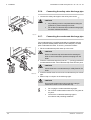
Connection of the combustion gas exhaust
pipe
5.7.5.
S
S
Insertion depth 30 mm
Mounting
Fit together the combustion gas exhaust pipes, without welding.
60/100mm
CAUTION
4
4
4
4
R000437-A
4
4
5.8
The flue gas discharge pipe must be smooth and
deburred.
Do not rest the pipes on the boiler.
Take in account the insertion depth of 30 mm when
measuring the length of pipe prior to cutting.
The pipes must allow no leakage of flue gases and be
resistant to corrosion.
Connect the pipes together without stress between
the sections.
The horizontal sections need to be constructed with a
gradient of 50 mm per metre: Back to the boiler.
Electrical connections
5.8.1.
Control unit
The boiler is not line- and neutral sensitive. The control unit is fully
integrated with the fan, venturi and gas block. The boiler is fully prewired. The PCB has a connection to the connection box with
instrument panel, via the HMI connector. The PCB has a RS232
connection for a PC/laptop via the RS232 connector. The main
characteristics of the control unit are described in the table below.
Power supply voltage
230 VAC/50Hz
Fuse rating F1 (230 VAC) 1,6 AT
32
02092014 - 7619497-02
Baxi MainEco Combi and System 24 - 28 - 35 / 18 - 24
5. Installation
The boiler is fitted with a 3-wire power supply cable (cable length 1,5
m) suitable for a 230VAC/50Hz power supply with phase/neutral/
earth system. The power supply cable is connected to the MAINS
connector. A spare fuse can be found in the housing of the control
system.
CAUTION
4
4
5.8.2.
When the power supply cable has to be replaced, it
must be ordered from BAXI. The power supply cable
should only be replaced by BAXI, or by an installer
certified by BAXI.
The switch must be easily accessible
Recommendations
WARNING
4
4
4
Only qualified professionals may carry out electrical
connections, always with the power off.
The boiler is entirely pre-wired. Do not modify the
connections inside the control panel.
Earth the appliance before making any electrical
connections.
Make the electrical connections of the boiler according to:
4 The instructions of the prevailing standards.
4 The instructions on the electrical diagrams provided with the
boiler.
4 The manufacturer’s instructions.
CAUTION
Separate the sensor cables from the 230 V cables.
02092014 - 7619497-02
33
5. Installation
Baxi MainEco Combi and System 24 - 28 - 35 / 18 - 24
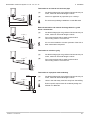
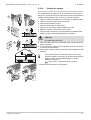
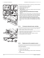
5.8.3.
Access to the connector block / Boiler HMI
The connection box with instrument panel is supplied separately as
standard with this unit. The connection box must be connected to the
automatic control unit using the cable supplied. To do this, proceed
as follows:
Under the boiler, there is a cable with a connector for the
control unit.
1
1. Carefully open the latch on the rear of the connection box using a
screwdriver.
2. Open the cover of the connection box.
3. Disconnect a pull relief clip. Turn the pull relief clip round.
4. Insert the plug from the cable into the HMI plug on the PCB for the
connection box.
5. Press the pull relief clip firmly into place.
6. Now connect the required external controllers to the remaining
connectors. To do this, proceed as follows:
- Disconnect a pull relief clip.
- Turn the pull relief clip round.
- Place the cable underneath the pull relief clip.
- Press the pull relief clip firmly into place.
- Connect the connection box and check that the box is sealed
properly.
7. Slide the User instruction card supplied into the guides underneath
the connection box.
8. Slide the connection box into the guides underneath the boiler
once all the connections have been made.
9. Secure the connection box using the screw found in the guides.
2
3
5
BUS
SCU
BUS On/of
OT
HMI
4
6
7
8
The connection box can also be attached to the wall using
the screw holes on the back of the connection box. The
connection box should be screwed to the wall using the
fixing points inside the unit.
9
R000411-C
The connection options for external system controls to the boiler HMI
are explained in the following paragraphs.
)For more detailed information, see: Connecting
External Controls Sheet.
5.8.4.
Connection options
Various external thermostats and controllers can be connected to the
control PCB.
4
+
3
2
1
Enable
- +
-
CH DHW
A
3
2
1
6
5
4
3
2
1
Status
Nc C No
2
BUS
Tout Tdhw BL
SCU
OT
B
R000734-A
34
Mains voltage
B
Low voltage
1
BUS On/off
HMI
A
On/off-OT connection is only suitable for:
4
24V power stealing thermostat
4
Potential free on/off thermostat
4
OT thermostat (iSense or qSense)
02092014 - 7619497-02
Baxi MainEco Combi and System 24 - 28 - 35 / 18 - 24
5. Installation
Please read in conjunction with separate sheet
"Connecting External Controls".
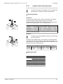
n Connecting modulating controller
The boiler is fitted with a OpenTherm connection as standard.
4
+
3
2
Enable
- +
1
-
CH DHW
3
2
1
6
5
4
3
2
1
2
Status
Nc C No
BUS
Tout Tdhw BL
SCU
1
BUS On/off
HMI
OT
R000450-A
As a result, modulating OpenTherm controllers can be connected
without further modifications.
4 In the case of a room temperature thermostat or a programmable
room thermostat, fit the thermostat in accordance with the
manufacturer’s instructions.
4 Connect the two-wire cable to terminals On/off-OT of the
connector.
n Connect on/off thermostat
The boiler is suitable for connecting a 2 wire on/off room thermostat
or weather compensator.
4
+
3
2
Enable
- +
1
-
CH DHW
3
2
1
6
5
4
3
2
1
2
Status
Nc C No
BUS
Tout Tdhw BL
SCU
1
BUS On/off
HMI
OT
R000450-A
4 In the case of a room temperature thermostat or a programmable
room thermostat, fit the thermostat in accordance with the
manufacturer’s instructions.
4 Connect the 2 wire 24V room thermostat to the On/off-OT
terminals of the connector.
4 Connect the power stealing thermostat to the On/off-OT terminals
of the connector.
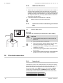
n Connecting the outside temperature sensor
An outside sensor can be connected to the Tout terminals of the
connector. In the case of an on/off thermostat, the boiler will control
the temperature with the set point from the internal heating curve.
4
+
3
2
Enable
- +
1
-
CH DHW
3
2
1
6
5
4
3
2
1
2
Status
Nc C No
BUS
Tout Tdhw BL
SCU
1
BUS On/off
HMI
OT
R000451-A
CAUTION
Check whether the outside sensor is suitable for this
boiler. A suitable outside sensor can be obtained as an
accessory.
A OpenTherm controller can also use this outside sensor.
The heating curve required must then be set on the
controller.
90
70
Heating curve setting
F
50
If an outside temperature sensor is connected, it is possible to adapt
the heating curve. The setting can be modified using parameters
p1, p"5, p"6 and p"7.
30
10
-20
-10
0
10
This is only possible with an iSense or qSense.
20
R000038-A
02092014 - 7619497-02
35
5. Installation
Baxi MainEco Combi and System 24 - 28 - 35 / 18 - 24
n Connect frost protection
Frost protection in combination with on/off thermostat
4
+
3
2
Enable
- +
1
-
CH DHW
3
2
1
6
5
4
3
2
1
Status
Nc C No
2
BUS
Tout Tdhw BL
SCU
1
If an on/off thermostat is used, it is advisable to protect any rooms
where there is risk of frost by using a frost thermostat. The radiator
valve in a room where there is a risk of frost must be open.
BUS On/off
HMI
OT
R000450-A
4 In rooms where there is a risk of frost, a frost thermostat (Tv)
should preferably be installed.
4 Connect the frost thermostat in parallel with an on/off room
thermostat (Tk) to the On/off-OT terminals of the connector.
When using a OpenTherm thermostat, a frost thermostat
cannot be connected in parallel to the On/off-OT
terminals. Implement frost protection for the central heating
system in combination with an external sensor.
Frost protection in combination with an outside sensor
4
+
3
2
Enable
- +
1
-
CH DHW
3
2
1
6
5
4
3
2
1
Status
Nc C No
2
BUS
Tout Tdhw BL
SCU
1
BUS On/off
HMI
OT
The central heating system can also be protected against frost in
combination with an outside sensor. The radiator valve in a room
where there is a risk of frost must be open. Connect the outside
sensor to the Tout terminals of the connector. The frost protection
functions as follows where an outside sensor is used:
R000451-A
4 At an outside temperature lower than -10°C (can be set with
parameter p30): the circulation pump switches on.
4 At an outside temperature higher than -10°C (can be set with
parameter p30): the circulation pump continues to run and then
switches off.
This is only possible with an iSense or qSense.
n Operation signal and failure signal (Status)
The alarm or operation signal is selected using parameter p40.
4
+
3
2
Enable
- +
1
-
CH DHW
3
2
1
6
5
4
3
2
1
Status
Nc C No
2
BUS
Tout Tdhw BL
SCU
1
BUS On/off
HMI
OT
R000453-A
36
4 If the boiler is operating, the operation signal can be switched via
a potential-free contact (maximum 230 VAC, 1 A) on the No and
C terminals of the connector.
4 If the boiler locks out, the alarm can be transmitted via a potentialfree contact (maximum 230 VAC, 1 A) on the Nc and C terminals
of the connector.
4 The external 3-way valve (230 VAC, 1 A) can be used when
connecting an indirectly heated calorifier via a volt-free contact.
The neutral position of the three-way valve can be set using
parameter p34. The three-way valve is connected as follows:
- Nc = Central heating
- No = Domestic hot water
- C = Phase on
4
This is only possible with an iSense or qSense.
4
Status connection can be used for standalone
condensate pump.
02092014 - 7619497-02
Baxi MainEco Combi and System 24 - 28 - 35 / 18 - 24
5. Installation
n Connect on/off contact (Enable)
A 10-230 V signal can be connected to the CH and DHW connectors
to switch the production of heating water or sanitary warm water on
or off.
4
+
3
2
Enable
- +
1
-
CH DHW
3
2
1
6
5
4
3
2
1
Status
Nc C No
2
BUS
Tout Tdhw BL
SCU
1
BUS On/off
HMI
OT
4 +=L
4 -=N
R000718-A
DANGER
If the power to the boiler is interrupted, a voltage will still
be present at connectors CH and DHW.
When using the Enable-CH connection a bridge must be
placed on the On/off-OT terminals of the connector.
The production of heating water or domestic hot water is
switched on as standard. The automatic control unit will
only respond to the switch and control the heating/
domestic hot water function once a 10-230 V signal has
been connected to the connectors. If the power to the boiler
is interrupted, the status of the CH and DHW input will be
reset to the factory setting (= enabled). Check whether this
is the status required.
n Connecting control panel
The control panel for the boiler is connected to connector BUS HMI.
4
+
3
2
Enable
- +
1
-
CH DHW
3
2
1
6
5
4
3
2
1
Status
Nc C No
2
BUS
Tout Tdhw BL
SCU
1
¼See chapter: "Access to the connector block / Boiler HMI", page
34
BUS On/off
HMI
OT
R000448-A
02092014 - 7619497-02
37
5. Installation
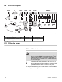
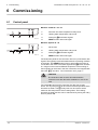
5.9
Baxi MainEco Combi and System 24 - 28 - 35 / 18 - 24
Electrical diagram
RS232
IT
PC
MAINS
PUMP
3WV
PUMP
1 2 3
1 2 3
1 2 3
1 2 3 4
GN/
YW
BR
BL
GN/
YW
BK
BL
BR
BK
BL
BK
BK
SENSORS
1
2 3 5
6
7
8
1
3 1
1
1
2
2
2
2
HL
FS
TR
TA
9 10 11 12 13
1 3 2
E
L N
P
230V, 50Hz
MAINS
PUMP
IT
PSU
3WV
PUMP PWM
PUMP A
3WV
PWM
PUMP
SENSORS
RS232
HMI
R000291-A
RS232 Connecting a computer
IT
Ignition transformer
E
P
PUMP A Circulation pump
3WV
3-way valve
Ignition/ionization electrode HL
FS
Power supply
TR
Return sensor
TA
Flow sensor
Safety thermostat PSU Storage parameter
HMI Connection box
Flow switch
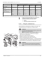
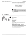
5.10 Filling the system
5.10.1.
Water treatment
WARNING
Do not add chemical products to the central heating water
without consulting BAXI. For example: antifreeze, water
softeners and/or products to increase or reduce the pH
value. These may cause faults in the boiler and damage
the heat exchanger.
Flush the central heating installation with at least 3x the
volume of the central heating installation. Flush the DHW
pipes with at least 20 times the volume of the pipes.
For an optimum functioning of the boiler, the water of the installation
must comply with following characteristics:
38
02092014 - 7619497-02
Baxi MainEco Combi and System 24 - 28 - 35 / 18 - 24
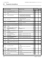
5. Installation
Total installed heat output (kW)
≤ 70
70 - 200
200 - 550
> 550
Degree of acidity (water
non-treated)
pH
7-9
7-9
7-9
7-9
Degree of acidity (water
treated)
pH
7 - 8.5
7 - 8.5
7 - 8.5
7 - 8.5
Conductivity at 25°C
µS/cm
≤ 800
≤ 800
≤ 800
≤ 800
Chlorides
mg/l
≤ 150
≤ 150
≤ 150
≤ 150
Other components
mg/l
<1
<1
<1
<1
°f
1 - 35
1 - 20
1 - 15
1-5
°dH
0.5 - 20.0
0.5 - 11.2
0.5 - 8.4
0.5 - 2.8
mmol/l
0.1 - 3.5
0.1 - 2.0
0.1 - 1.5
0.1 - 0.5
Total water
hardness(1)
(1) For installations that are heated at constant high temperatures with a total installed heat output; up to 200 kW a maximum total water hardness
of 8.4 °dH (1.5 mmol/l, 15 °f) applies and for above 200 kW a maximum total water hardness of 2.8 °dH (0.5 mmol/l, 5 °f) applies
Failure to flush and add inhibitor to the system will
invalidate the appliance warranty. Reputable
manufacturers and their products include:
5.10.2.
4
Fernox
4
Sentinel Performance Solution Ltd
Filling the condensate trap
Check whether the condensate trap is filled up to the mark. If the
condensate trap has to be topped up, proceed as follows:
CAUTION
First remove the front housing of the boiler so that you can
disconnect the condensate trap.
¼See paragraph: "Open the boiler", page 53
1
2
5
1. Move the lever underneath the hydroblock to the right to
disconnect the condensate trap.
2. Remove the condensate trap and clean it.
3. Replace the seal ring for the condensate trap.
4. Fill the condensate trap with water up to the mark.
5. Press the condensate trap firmly into the j opening provided for
it underneath the boiler. The condensate trap must click into place.
6. Check whether the condensate trap is solidly fitted in the boiler.
6
3
CAUTION
Fill the condensate trap with water before starting the
boiler to avoid combustion products escaping from the
boiler.
4
R000431-B
02092014 - 7619497-02
39
5. Installation
Baxi MainEco Combi and System 24 - 28 - 35 / 18 - 24
5.10.3.
Filling the system
CAUTION
4
4
Before filling, open the valves on every radiator in the
installation.
Ensure that the boiler is switched off.
1
2
3
4
T000181-B
1. Fill the system with clean tap water (advised water pressure is
between 1 and 2 bar).
2. Check the tightness of the water connections.
3. Turn the boiler on.
After the power is switched on, the boiler always runs
through an automatic venting programme lasting approx.
4 minutes (During filling, air can escape from the system
via the automatic air vent). If necessary, top up the water
level in the heating system (recommended hydraulic
pressure between 1 and 2 bar).
50
°C
100
20
120
bar
0
4
3
CAUTION
1
2
R000733-A
40
When venting, ensure that no water enters or makes
contact with the casing and electrical parts of the boiler.
02092014 - 7619497-02
Baxi MainEco Combi and System 24 - 28 - 35 / 18 - 24
5. Installation
5.10.4.
Venting the system
It is essential that you bleed any air in the calorifier, the conduits or
the taps to prevent the annoying noises likely to be produced during
heating or when tapping water. To do this, proceed as follows:
1
1.
2.
3.
4.
5.
6.
7.
1
2
3
4
2
3
11
Open the valves on all radiators connected to the heating system.
Set the room thermostat as high as possible.
Wait until the radiators are hot.
Ensure that the boiler is switched off.
Wait around 10 minutes until the radiators are cold.
Bleed the radiators. Start with the lower floors.
Open the bleed connection using the bleed key provided whilst
keeping a rag pressed against the bleed connection.
CAUTION
The water may still be hot.
5
8. Wait until water comes out of the bleed valve and then close the
bleed connection.
9. Turn the boiler on. A vent cycle of a duration of around 4 minutes
is carried out automatically.
10.After venting, check whether the pressure in the installation is still
sufficient.
4
6
C
A
B
If the water pressure is lower than 0.8 bar, more water
should be added. If necessary, top up the water level in the
heating system (recommended hydraulic pressure
between 1 and 2 bar).
¼See chapter: "Filling the system", page 40
11.Set the room thermostat or the regulator.
7
8
R000712-A
02092014 - 7619497-02
41
6. Commissioning
Baxi MainEco Combi and System 24 - 28 - 35 / 18 - 24
6
Commissioning
6.1
Control panel
MainEco Combi 24 - 28 - 35
1
2
3
4
T002247-D
1
Domestic hot water temperature rotary knob
2
Heating water temperature rotary knob
3
Sweep key B and Status signals
4
RESET-button and on/off signal
MainEco System 18 - 24
1
2
3
4
R000714-A
1
No function
2
Heating water temperature rotary knob
3
Sweep key B and Status signals
4
RESET-button and on/off signal
The instrument panel for the connection box has 2 push buttons with
signals. The signals provide information about the operating condition
of the boiler. The RESET button lights up green when the boiler is
connected to the mains. The status signal for the B button can flash
in a range of colours and at different frequencies. The meaning of
these signals can be found in the User instruction card supplied with
the boiler. ¼See also: "User instruction card", page 71
CAUTION
The instruction card must be slid underneath the
connection box after the boiler installation or use of the
card.
The instrument panel for the connection box also has 2 rotary
knobs. The N rotary knob can be used to set the temperature of the
domestic hot water. The D rotary knob can be used to set the
maximum flow temperature of the heating water. The heating/
domestic hot water function can be switched off by turning the rotary
knob to position off.
42
02092014 - 7619497-02
Baxi MainEco Combi and System 24 - 28 - 35 / 18 - 24
6.2
6. Commissioning
Check points before commissioning
6.2.1.
Preparing the boiler for commissioning
WARNING
Do not put the boiler into operation if the supplied gas is
not in accordance with the approved gas types.
Preparatory procedure for boiler commissioning:
4 Check that the gas type supplied matches the data shown on the
boiler’s data plate.
4 Check the hydraulic circuit.
4 Check the water pressure in the heating system.
4 Check the electrical connections to the thermostat and the other
external controls.
4 Check the other connections.
6.2.2.
Hydraulic circuit
4 Use the pressure gauge to check the water pressure in the heating
system. The hydraulic pressure must reach a minimum of 0.8
bar. If necessary, top up the water level in the heating system
(recommended hydraulic pressure between 1 and 2 bar).
4 Check the condensate discharge trap; it must be filled with clean
water up to the mark.
4 Check that there are no leaks on the hydraulic connections.
6.2.3.
Electrical connections
4 Check the electrical connections, particularly the earth.
4 Check the electrical connections to the thermostat and the other
external controls.
6.3
Commissioning the boiler
WARNING
Initial commissioning must be done by a qualified
professional.
02092014 - 7619497-02
43
6. Commissioning
Baxi MainEco Combi and System 24 - 28 - 35 / 18 - 24
CAUTION
On first firing the boiler, an odour may be present for a
short period.
1.
2.
3.
4.
Open the main gas supply.
Open the gas valve on the boiler.
Turn the boiler on.
Set the controls (thermostats, control system) so that they request
heat.
5. The boiler will begin an automatic venting-programme (which lasts
approx. 4 minutes) and will do this every time the power supply is
isolated. Both push buttons on the instrument panel light up green
during the venting cycle.
The boiler will begin an automatic venting-programme
(which lasts approx. 4 minutes) and will do this every time
the power supply is isolated.
6. Check the boiler pump venting. Remove the middle screw if
necessary before venting the pump (Central heating pump).
7. Check the gas connections into and out of the gas block in the
boiler for tightness.
The current operating condition of the boiler is shown by the status
signal on the instrument panel. The status signal for the B button
can flash in a range of colours and at different frequencies. The
meaning of these signals can be found in the User instruction card
supplied with the boiler.
See also:
¼ "User instruction card", page 71
¼ "Error codes", page 63
Error during the start-up procedure:
4 Both buttons on the instrument panel are in the out position:
- Check the mains supply voltage
- Check the main fuses
- Check the connection cable to the connection box.
- Check the fuses on the control panel: (F1 = 1,6 AT 230VAC)
- Check the connection between the mains lead and the
MAINS connector for the automatic control unit.
4 In the event of a fault, the status signal for the B button flashes
red. Press the J button for 5 seconds to restart the boiler.
44
02092014 - 7619497-02
Baxi MainEco Combi and System 24 - 28 - 35 / 18 - 24
6.4
6. Commissioning
Gas settings
The boiler is preset in the factory to operate on natural gas
G20.
6.4.1.
Gas circuit
WARNING
Ensure that the boiler is switched off.
1. Remove the front panel.
¼See paragraph: "Open the boiler", page 53
2. Check that the boiler is properly set for the type of gas used (See
the identification plate on top of the boiler ).
WARNING
¼To ascertain the gas types permitted, see chapter:
"Technical specifications", page 17
3. Open the main gas supply.
4. Open the gas valve on the boiler.
5. Check the gas supply pressure at the pressure test point C on the
gas inlet pipe. The pressure must be the same as the one shown
on the rating plate.
C
See the diagram for the position of measuring point C for
the inlet gas pressure.
6. Purge the gas supply pipe by unscrewing the screw from the
measure point C. Tighten the measurement point when the pipe
has been sufficiently purged.
7. Check the leak tightness of the gas pipe, including the gas block.
R000736-A
6.4.2.
Checking combustion
1. Unscrew the plug of the flue gas measurement point.
2. Insert the probe for the flue gas analyser into the measurement
opening.
WARNING
Ensure that the opening around the sensor is completely
sealed when taking measurements.
CAUTION
T003127-B
02092014 - 7619497-02
The flue gas analyser must have a minimum accuracy of
±0.25% CO2.
45
6. Commissioning
Baxi MainEco Combi and System 24 - 28 - 35 / 18 - 24
n Set the boiler to full load
1. Continue pressing for around 3 seconds on the B key. The status
signal for the B button is orange and always flashes green
briefly; Part load is set.
2. Press the B button again 2 times. The status signal for the B
button is orange and always goes off briefly 2 times; Full load is
set.
The full load status can only be reached via the part load
status.
3. Measure the percentage CO2 in the flue gases (Front panel
removed).
Full load CO2 must be between 9.15 and 9.50 %.
n Set the boiler to part load
1. Continue pressing for around 3 seconds on the B key. The status
signal for the B button is orange and always flashes green
briefly; Part load is set.
2. Measure the percentage CO2 in the flue gases (Front panel
removed).
Part load CO2 must be between 8.70 and 9.05 %.
WARNING
There MUST remain a "gap" between the full load and part
load values. The full load value must be 0.4% higher than
the part load value.
3. Briefly press the RESET button to return the boiler to normal
operating status.
46
02092014 - 7619497-02
Baxi MainEco Combi and System 24 - 28 - 35 / 18 - 24
6. Commissioning
Set Boiler to Maximum Rate
Allow the combustion to stabilise. Do not insert probe to avoid
‘flooding’ the analyser.
Perform Flue Integrity Combustion Check
Insert the analyser probe into the air inlet test point,
allowing the reading to stabilise.
Verify Flue Integrity
Indication that products of combustion & inlet
air are mixing - further investigation is
required. Check all flue components are
correctly assembled, fixed & supported.
Check the flue & terminal are unobstructed.
Is O2 ≥ 20.6% and
CO2 < 0.2% ?
No
Is O2 ≥ 20.6% and
CO2 < 0.2% ?
Yes
Check CO & Combustion Ratio at
Maximum Rate
Whilst the boiler is still operating at maximum
insert the analyser probe into the flue gas
test point, allowing the reading to stabilise.
No
Is CO < 350ppm
and CO/CO2 ratio
< 0.004 ?
Yes
Set Boiler to Minimum Rate
Allow the combustion to stabilise. Do not
insert probe to avoid ‘flooding’ the analyser.
Yes
No
TURN APPLIANCE OFF !
Call 0844 871 1555 for advice.
The appliance MUST NOT be commissioned
until all problems are identified and resolved.
Verify Integrity of Seals
Check all burner seals, internal flue seals,
door & case seals. Replace any seals that
appear unsound.
Is CO < 350ppm
and CO/CO2 ratio
< 0.004 ?
Yes
No
TURN APPLIANCE OFF !
Call 0844 871 1555 for advice.
The appliance MUST NOT be commissioned
until all problems are identified and resolved.
If commissioning cannot befully completed
the appliance must be disconnected from the
gas supply in accordance with the GSIUR.
Note: Check & record the CO & combustion
ratio at both maximum & minimum rates
before calling 0844 871 1555.
Check CO & Combustion Ratio at
Minimum Rate
Whilst the boiler is operating at minimum
insert the analyser probe into the flue gas
test point, allowing the reading to stabilise.
Is CO < 350ppm
and CO/CO2 ratio
< 0.004 ?
BOILER OPERATING SATISFACTORILY.
NO FURTHER ACTION REQUIRED
Ensure test points are capped, the boiler
case front panel is correctly fitted & secured
and all other commissioning procedures
completed. Complete the ‘Benchmark’
Checklist, recording the CO & combustion
ratio readings as required.
R000715-A
02092014 - 7619497-02
47
6. Commissioning
Baxi MainEco Combi and System 24 - 28 - 35 / 18 - 24
6.4.3.
Setting the air/gas ratio
1. Unscrew the plug of the flue gas measurement point.
2. Insert the probe for the flue gas analyser into the measurement
opening.
WARNING
Ensure that the opening around the sensor is completely
sealed when taking measurements.
CAUTION
T003127-B
The flue gas analyser must have a minimum accuracy of
±0.25% CO2.
n Set the boiler to full load
1. Continue pressing for around 3 seconds on the B key. The status
signal for the B button is orange and always flashes green
briefly; Part load is set.
2. Press the B button again 2 times. The status signal for the B
button is orange and always goes off briefly 2 times; Full load is
set.
4
4
The full load status can only be reached via the part
load status.
See drawing for the position of control screw A for full
load.
3. Set the percentage CO2 for the gas type being used to the nominal
value. This should always be inside the highest and lowest setting
limit.
A
B
4
4
If the percentage CO2 is too low, turn the screw A
anticlockwise for a higher percentage.
If the percentage CO2 is too high, turn the screw A
clockwise for a lower percentage.
R000592-B
Full load CO2 must be between 9.15 and 9.50 %.
n Set the boiler to part load
B
A
B
1. Continue pressing for around 3 seconds on the B key. The status
signal for the B button is orange and always flashes green
briefly; The low speed mode is parameterised.
See drawing for the position of control screw B for part load.
R000591-B
48
02092014 - 7619497-02
Baxi MainEco Combi and System 24 - 28 - 35 / 18 - 24
6. Commissioning
2. Set the percentage CO2 for the gas type being used inside the
highest and the lowest setting limit, as determined after the full
load setting. (Front panel removed).
4
4
If the percentage CO2 is too high, turn the screw B
anticlockwise for a lower percentage.
If the percentage CO2 is too low, turn the screw B
clockwise for a higher percentage.
Part load CO2 must be between 8.70 and 9.05 %.
WARNING
There MUST remain a "gap" between the full load and part
load values. The full load value must be 0.4% higher than
the part load value.
3. Briefly press the RESET button to return the boiler to normal
operating status.
6.5
Finalizing work
1.
2.
3.
4.
T001522-A
02092014 - 7619497-02
Remove the measuring equipment.
Put the flue gas sampling plug back in place.
Refit the front panel.
Raise the temperature in the heating system to approximately
70°C.
5. Shut down the boiler.
6. After about 10 minutes, vent the air in the heating system.
7. Switch on the boiler.
8. Check the tightness of the flue gases evacuation and air inlet
connections.
9. Checking the hydraulic pressure. If necessary, top up the water
level in the heating system (recommended hydraulic pressure
between 1 and 2 bar).
10.Tick the gas category used on the data plate.
11.Explain the operation of the installation, the boiler and the
regulator to the users.
12.Slide the User instruction card supplied into the guides underneath
the connection box.
13.Fill in Commissioning sheet, can be found in the appendix.
14.Give all the instruction manuals to the user.
49
6. Commissioning
6.6
Baxi MainEco Combi and System 24 - 28 - 35 / 18 - 24
Parameter descriptions
Factory setting
Parameter Description
Adjustment range
Combi
System
24
28
35
18
24
80
80
80
80
80
55
55
55
55
55
Heating / DHW mode
0 = Heating deactivated / DHW deactivated
1 = Heating activated / DHW activated
2 = Heating activated / DHW deactivated
3 = Heating deactivated / DHW activated
1
1
1
1
1
p4
ECO mode
0 = Comfort
1 = Energy-saving mode
2 = Management using a programmable
thermostat
2
2
2
2
2
p5
Post-circulation of the pump
1 to 98 minutes
99 minutes = continuous
2
2
2
2
2
p1
Flow temperature: TSET
20 to 90 °C
p2
Domestic hot water temperature:
TSET
40 to 65 °C
p3
p17
Maximum fan volume flow (Heating) G20 (x100)
39
39
60
36
47
p18
Maximum fan volume flow (DHW)
G20 (x100)
47
56
70
36
47
p19
Minimum fan volume flow (Heating
+DHW)
G20 (x100)
11
11
15
11
11
p20
Minimum fan volume flow (offset)
G20
80
80
60
80
80
p21
Starting volume flow
Do not modify (x100)
23
23
30
23
23
p23
Maximum flow temperature of
system
20 to 90 °C
90
90
90
90
90
p24
Time factor of average flow
calculation
Do not modify
(x10 seconds)
35
35
35
35
35
p25
Heat curve set point (Maximum
outside temperature)
0 to 30 °C
(Only with an outside temperature sensor)
20
20
20
20
20
p26
Heat curve set point (Flow
temperature)
0 to 90 °C
(Only with an outside temperature sensor)
20
20
20
20
20
p27
Heat curve set point (Minimum
outside temperature)
-30 to 0 °C
(Only with an outside temperature sensor)
-15
-15
-15
-15
-15
p28
Minimum pump speed for central
2 - 10 (x 10 %)
heating operation (Setting the pump
speed)
2
2
2
2
2
p29
Maximum pump speed for central
2 - 10 (x 10 %)
heating operation (Setting the pump
speed)
7
7
10
10
10
p30
Antifreeze temperature
-10
-10
-10
-10
-10
1
1
1
1
1
from - 30 to 0°C
0 = Stop
1 = Start(1)
2 = Management using a programmable
thermostat
p31
Legionella protection
p32
Set point increase for calorifier
0 to 25 °C
15
15
15
15
15
p33
DHW cut-in temperature DHW
sensor
from 2 to 15°C
4
4
4
4
4
p34
Control of external 3-way valve
0 = Normal
1 = Reverse
0
0
0
0
0
p35
Boiler type
0 = Heating and instant domestic hot water
1 = Heating only
0
0
0
1
1
(1) After commissioning, the boiler will operate once a week at 65°C for DHW.
50
02092014 - 7619497-02
Baxi MainEco Combi and System 24 - 28 - 35 / 18 - 24
6. Commissioning
Factory setting
Parameter Description
Adjustment range
Combi
System
24
28
35
18
24
1
1
1
1
1
p36
Shutdown input function
1 = Shutdown without frost-protection
2 = Shutdown with frost protection
3 = Lock-out with frost protection (Pump only)
p37
Minimum gas pressure switch (GpS)
0 = Not connected
1 = Connected
0
0
0
0
0
p38
Heat recovery unit (HRU)
0 = Not connected
1 = Connected
0
0
0
0
0
p39
Flue gas damper running time
0 to 255 seconds
0
0
0
0
0
p40
Fault relay function
0 = Operation signal
1 = Alarm signal
2 = External 3-way valve
2
2
2
2
2
p41
Maintenance message
Do not modify
0
0
0
0
0
p42
Service operating hours
Do not modify
175 175 175 175 175
p43
Service burning hours
Do not modify
30
30
30
30
30
Venting cycle
0 = Stop
1 = Multiple speed pump
2 = Modulating pump
1
1
1
1
1
p44
(1) After commissioning, the boiler will operate once a week at 65°C for DHW.
02092014 - 7619497-02
51
7. Switching off the boiler
Baxi MainEco Combi and System 24 - 28 - 35 / 18 - 24
7
Switching off the boiler
7.1
Installation shutdown
If the central heating system is not used for a long period, we
recommend switching the boiler off.
4 Switch off the boiler electrical power supply.
4 Shut off the gas supply.
4 Ensure that the boiler and system are protected against frost
damage.
7.2
Antifreeze protection
CAUTION
Drain the boiler and central heating system if you are not
going to use your home or the building for a long time and
there is a chance of frost.
Set the temperature control low, for example at 10°C.
To prevent radiators and the system from freezing in rooms where
there is a risk of frost (e.g. a garage or storage room), a frost
thermostat or outside sensor can be connected to the boiler.
¼See also: "Connection options", page 34.
CAUTION
4
4
4
4
The antifreeze protection does not function if the
boiler is switched off.
The integrated protection system only protects the
boiler, not the installation.
Open the valves on all radiators connected to the
heating system
If the boiler has been placed in a room at risk of frost,
the condensate drain and condensate trap should
preferably be protected against freezing with a frost
protection cable.
When the heating water temperature in the boiler falls by too much,
the integrated protection system in the boiler starts up. This protection
functions as follows:
4 If the water temperature is lower than 7°C, the heating pump starts
up.
4 If the water temperature is lower than 4°C, the boiler starts up.
4 If the water temperature is higher than 10°C, the boiler shuts down
and the circulation pump continues to run for a short time.
52
02092014 - 7619497-02
Baxi MainEco Combi and System 24 - 28 - 35 / 18 - 24
8. Checking and maintenance
8
Checking and maintenance
8.1
General instructions
WARNING
4
Maintenance operations must be done by a qualified
engineer.
An annual inspection is compulsory.
4
Only original spare parts must be used.
4
4 Carry out the inspection and standard maintenance operations
once a year.
4 Carry out specific maintenance operations if necessary.
8.2
Standard inspection and maintenance operations
WARNING
Ensure that the boiler is switched off. Electrical isolation
can be checked at the electrical test point.
CAUTION
4
R000695-B
4
8.2.1.
Always examine any seals or gaskets, replacing
where necessary. Where a seal or gasket is supplied
with a spare part it should be used, irrespective of the
condition of the original.
Use only original spare parts that are intended for use
with this type of boiler.
Open the boiler
1. Unscrew the 2 screws, located on the front panel.
1
1
R000346-A
02092014 - 7619497-02
53
8. Checking and maintenance
Baxi MainEco Combi and System 24 - 28 - 35 / 18 - 24
2. Remove the front panel.
3
2
2
R000405-A
8.2.2.
Checking the hydraulic pressure
The hydraulic pressure must reach a minimum of 0.8 bar. If
necessary, top up the water level in the heating system
(recommended hydraulic pressure between 1 and 2 bar).
CAUTION
4
4
Before filling, open the valves on every radiator in the
installation.
Ensure that the boiler is switched off.
1. Fill the system with clean tap water (advised water pressure is
between 1 and 2 bar).
2. Check the tightness of the water connections.
3. Turn the boiler on.
50
°C
100
20
120
bar
0
4
3
1
2
R000733-A
8.2.3.
Checking the expansion vessel
Check the expansion vessel and replace it if necessary.
Initial pressure of the expansion vessel is 1.0 bar (± 0.2).
8.2.4.
Checking the ionization current
Check the ionization current at full load and low load. The value is
stable after 1 minute. If the value lies below 3 µA, replace the ignition
electrode.
¼See chapter: "Replacing the ionization/ignition electrode", page
58.
54
02092014 - 7619497-02
Baxi MainEco Combi and System 24 - 28 - 35 / 18 - 24
8.2.5.
8. Checking and maintenance
Checking the DHW transfer capacity
If tap capacity falls significantly (due to insufficient temperature and/
or flow rate), clean the plate heat exchanger (hot water side) and the
tap water cartridge:
¼See chapter: "Cleaning the plate heat exchanger", page 59.
8.2.6.
Checking the flue gas discharge and the air
supply
Check the tightness of the flue gases evacuation and air inlet
connections.
R000406-A
8.2.7.
Checking combustion
Measure the percentage CO2 in the flue gases. To do this, proceed
as follows:
1. Heat the water in the boiler to a temperature of approx. 70 °C.
Allow the combustion to stabilise before inserting the
combustion analyser probe into the measurement
opening. This will prevent saturation of the analyser.
T003127-B
2. Unscrew the plug of the flue gas measurement point.
3. Insert the probe for the flue gas analyser into the measurement
opening.
4. Measure the percentage CO2 in the flue gases. Perform
measurements at full capacity and low capacity. Compare this with
the control value.
¼For further information: See chapter:
"Checking combustion", page 45
8.2.8.
Checking the automatic air vent
1. Check that the automatic bleed is working (This is visible on the
right on top of the boiler).
2. The air vent can be closed off with the cap that can be found next
to it.
3. If any leaks are detected, replace the air vent.
R000350-A
02092014 - 7619497-02
55
8. Checking and maintenance
Baxi MainEco Combi and System 24 - 28 - 35 / 18 - 24
8.2.9.
Checking the condensate trap
CAUTION
1
2
First remove the front housing of the boiler so that you can
disconnect the condensate trap.
1. Move the lever underneath the hydroblock to the right to
disconnect the condensate trap.
2. Remove the condensate trap and clean it.
3. Replace the seal ring for the condensate trap.
4. Fill the condensate trap with water up to the mark.
5. Press the condensate trap firmly into the j opening provided for
it underneath the boiler. The condensate trap must click into place.
6. Check whether the condensate trap is solidly fitted in the boiler.
5
6
3
4
R000431-B
56
02092014 - 7619497-02
Baxi MainEco Combi and System 24 - 28 - 35 / 18 - 24
8. Checking and maintenance
8.2.10.
Checking the burner and cleaning the heat
exchanger
CAUTION
Always examine any seals or gaskets, replacing where
necessary. Where a seal or gasket is supplied with a spare
part it should be used, irrespective of the condition of the
original.
3
5
6
2
5
4
2
7
8
10
12
9
11
13
1. Ensure that the boiler is switched off. Close the gas valve of the
boiler. Remove the front panel.
2. Take the bracket off the flue gas discharge pipe. Remove the flue
gas discharge pipe.
3. Remove the air inlet flue on the venturi.
4. Unscrew the gland underneath the gas block.
5. Open the protective cover for the fan on the top and remove all the
plugs from the PCB.
6. Close the fan’s protective cover.
7. Disassemble the ignition electrode. Check the ignition electrode
for wear. Replace if necessary.
¼See also: "Replacing the ionization/ignition electrode", page
58
8. Unclip the 2 locking clips that attach the gas/air unit to the heat
exchanger.
9. Remove the gas/air unit by moving the gas/air unit upwards and
then forwards.
10.Tilt the burner and remove it, along with the heat exchanger
gasket.
11.Use a vacuum cleaner fitted with a special endpiece (accessory)
to clean the top part of the heat exchanger (combustion chamber).
12.Thoroughly clean with the vacuum cleaner again without the top
cleaning brush on the endpiece.
13.Check (using a mirror, for example) whether any dust can still be
seen. If so, hoover it up.
14.The burner does not require any maintenance, it is self-cleaning.
Check that there are no cracks and/or other tears on the surface
of the dismantled burner. If this is not the case, replace the burner.
15.Install the ignition electrode.
16.To re-assemble, perform the above actions in reverse order.
CAUTION
14
15
16
17
4
4
Remember to replace the plugs on the PCB for the
gas/air unit.
Check that the gasket is correctly positioned between
the mixing elbow and the heat exchanger.
(Completely flat in the appropriate groove means it is
leak proof).
17.Open the gas inlet valves and switch on the mains supply to the
boiler.
T004777-B
02092014 - 7619497-02
57
8. Checking and maintenance
8.3
Baxi MainEco Combi and System 24 - 28 - 35 / 18 - 24
Specific maintenance operations
WARNING
Ensure that the boiler is switched off. Electrical isolation
can be checked at the electrical test point.
CAUTION
4
R000695-B
4
Always examine any seals or gaskets, replacing
where necessary. Where a seal or gasket is supplied
with a spare part it should be used, irrespective of the
condition of the original.
Use only original spare parts that are intended for use
with this type of boiler.
If the standard inspection and maintenance operations have revealed
the necessity to carry out additional maintenance work, proceed as
follows, depending on the nature of the work:
8.3.1.
Replacing the ionization/ignition electrode
Replace the ionization/ignition electrode in the following cases:
4 Ionization current <3 µA.
4 Electrode worn.
2
1.
2.
3.
4.
5.
3
2
Open the protective cover for the fan at the top.
Remove the ignition electrode plugs from the PCB.
Unscrew the 2 screws on the ignition electrode. Remove the unit.
Fit the new ionisation/ignition electrode.
To re-assemble, perform the above actions in reverse order.
1
R000433-A
58
02092014 - 7619497-02
Baxi MainEco Combi and System 24 - 28 - 35 / 18 - 24
8.3.2.
1
2
8. Checking and maintenance
Replacing the 3-way valve
If it becomes necessary to replace the 3-way valve, proceed as
follows:
1. Close the main water valve.
2. Drain the boiler:
- Open a domestic hot water tap to release the pressure and drain
any water from the circuit.
- Connect the filling loop to the heating return connection.
- Open the isolation tap and drain the circuit into a suitable
receptacle.
- When the water has stopped flowing, close all the isolation taps.
3. Open the protective cover for the fan at the top.
4. Disconnect the three-way valve cable from the automatic control
unit.
5. Unclip the locking clip that holds the 3-way valve.
6. Dismantle the 3-way valve by rotating a screwdriver.
7. Remove the 3-way valve.
8. To re-assemble, perform the above actions in reverse order.
4
3
7
CAUTION
Be careful of the positioning cams on the 3-way valve.
6
5
R000400-A
8.3.3.
Cleaning the plate heat exchanger
Depending on the water quality and the operating mode, limescale
deposits may form in the plate exchanger. As a general rule, a
periodic inspection, along with cleaning, if necessary, is sufficient.
The following factors may affect the periodicity:
4 Water hardness.
4 Composition of the limescale.
4 Number of hours’ operation of the boiler.
4 Draw-off rate.
4 Domestic hot water set point temperature.
02092014 - 7619497-02
59
8. Checking and maintenance
1
Baxi MainEco Combi and System 24 - 28 - 35 / 18 - 24
If descaling of the plate exchanger is necessary, proceed as follows:
2
Gas/Gaz
3
4
5
1.
2.
3.
4.
Ensure that the boiler is switched off.
Close the gas valve of the boiler.
Close the main water valve.
Drain the boiler:
- Open a domestic hot water tap to release the pressure and drain
any water from the circuit.
- Connect the filling loop to the heating return connection.
- Open the isolation tap and drain the circuit into a suitable
receptacle.
- When the water has stopped flowing, close all the isolation taps.
5. Unscrew the screw on the left-hand side of the heat exchanger.
6. Remove the plate heat exchanger by moving the left-hand side
forwards and tipping the right-hand side out of the bracket.
7. Clean the plate heat exchanger with a descaling product (citric
acid pH 3). To do this, a specific cleaning appliance is available
as an accessory. After cleaning, rinse thoroughly under running
water.
6
R000741-A
8.3.4.
The plate heat exchanger should be removed in order to clean the
tap water cartridge. Then proceed as follows:
1
a
Cleaning the domestic water cartridge
1.
2.
3.
4.
b
Dismantle the domestic water cartridge by rotating a screwdriver.
Remove the domestic water cartridge.
Clean or replace the domestic water cartridge if required.
Re-assemble all of the components.
2
3
R000401-A
8.3.5.
Replacement of the expansion vessel
The following procedures have to be carried out before the expansion
vessel can be replaced:
4 Close the gas valve of the boiler.
4 Close the main water valve.
4 Close the flow central heating pipe and the return central heating
pipe.
4 Drain the boiler.
60
02092014 - 7619497-02
Baxi MainEco Combi and System 24 - 28 - 35 / 18 - 24
8. Checking and maintenance
The expansion vessel is inside the boiler at the rear. To replace the
expansion vessel, the front section of the boiler should be removed
first.
n Removing the front section of the boiler
2
1
T005059-A
1. Disconnect the flue gas discharge and air flow pipes from the
boiler.
2. Remove the connection box.
3. Disconnect all incoming and outgoing pipes from the underside of
the boiler.
4. Disconnect the gas supply pipe GAS / GAZ from the boiler.
5. Remove the condensate trap and drain hose.
To check how to remove the condensate trap, see: ¼
"Checking the condensate trap", page 56.
6. Disconnect the expansion vessel hose from the underside of the
boiler.
7. Press down the mounting clip on top of the boiler and remove the
front of the boiler.
n Remove the expansion vessel
1. Bring the tab above the expansion vessel forwards and hold onto
it while disconnecting the expansion vessel.
2. Move the expansion vessel slightly upwards and lift the vessel
from the mounting bracket.
3. Tip the expansion vessel forwards and allow it drop slightly.
4. Carefully lift the expansion vessel out of the boiler.
5. Replace the defective expansion vessel.
6. To re-assemble, perform the above actions in reverse order.
2
3
1
CAUTION
4
4
Replace all removed gaskets.
4
Fill the system with clean tap water (advised water
pressure is between 1 and 2 bar). ¼ "Water
treatment", page 38
R000351-A
8.3.6.
Re-assembling the boiler
1. Follow the procedure in reverse to re-assemble all of the
components.
CAUTION
Always examine any seals or gaskets, replacing where
necessary. Where a seal or gasket is supplied with a spare
part it should be used, irrespective of the condition of the
original.
2. Fill the condensate trap with water up to the mark.
3. Put the condensate trap back in place.
02092014 - 7619497-02
61
8. Checking and maintenance
Baxi MainEco Combi and System 24 - 28 - 35 / 18 - 24
4. Carefully open the main water valve, fill the installation, vent it and,
if need be, top it up with water. The hydraulic pressure must be a
minimum of 0,8 bars. Check for any water leaks.
5. Check the seals on the gas and water connections.
6. Switch the boiler back on.
7. Check the setting of the gas/air ratio and, if necessary, correct it.
¼See chapter: "Checking combustion", page 45
¼See chapter: "Setting the air/gas ratio", page 48
62
02092014 - 7619497-02
Baxi MainEco Combi and System 24 - 28 - 35 / 18 - 24
9
Troubleshooting
9.1
Error codes
9. Troubleshooting
MainEco Combi 24 - 28 - 35
1
2
3
4
T002247-D
1
Domestic hot water temperature rotary knob
2
Heating water temperature rotary knob
3
Sweep key B and Status signals
4
RESET-button and on/off signal
MainEco System 18 - 24
1
2
3
4
R000714-A
1
No function
2
Heating water temperature rotary knob
3
Sweep key B and Status signals
4
RESET-button and on/off signal
The status signal for the B button can flash in a range of colours and
at different frequencies. The meaning of these signals can be found
in the User instruction card supplied with the boiler.
¼See also: "User instruction card", page 71.
CAUTION
The instruction card must be slid underneath the
connection box after the boiler installation or use of the
card.
9.2
Shutdowns and lock-outs
9.2.1.
Blocking
A (temporary) blocking mode is a boiler operating function caused by
an unusual situation. The boiler control will try to re-start several
times. The boiler will start up again after the blocking conditions have
been eliminated.
In the event of a shutdown, the status signal for the B button flashes
green. The meaning of the shutdown codes can be found in the
shutdown table.
02092014 - 7619497-02
63
9. Troubleshooting
Status signals
Baxi MainEco Combi and System 24 - 28 - 35 / 18 - 24
Description
Code
Shutdown code 1
Temperature protection
(1 times green signal)
5v[1 / 5v[2 / 5v[7
Shutdown code 2
Shutdown input
(2 times green signal)
5v[10 / 5v[11
Shutdown code 3
Flame loss
(3 times green signal)
5v[22
Shutdown code 4
Communication fault
(4 times green signal)
5v[12 / 5v[13 / 5v[21
Shutdown code 5
Parameter or identification fault 5v[0 / 5v[16 / 5v[17 / 5v[18 / 5v[19
(5 times green signal)
Shutdown code 6
Miscellaneous
(6 times green signal)
5v[15 / 5v[25
The boiler starts up again automatically when the reason
for the blocking has been removed.
The shutdown codes from the status signals are related to the
shutdown codes that can be read by the Recom software or a suitable
controller. The meaning of the shutdown codes can be found in the
shutdown table:
Shutdown
code
Description
Probable causes
5v[0
Parameter error
5v[1
Maximum flow temperature 4
exceeded
Non-existent or insufficient
circulation
Maximum increase of the 4
flow temperature has been
exceeded
4
Non-existent or insufficient
circulation
Sensor error
4
Parameters faulty
Checking / solution
4
Reset df and dV
4
4
Restore parameters with Recom
Check the circulation (direction, pump,
valves)
Reasons for the heat demand
Check the circulation (direction, pump,
valves)
Check the water pressure
4
4
4
5v[2
4
4
4
4
4
Maximum difference
between the flow and return
temperature exceeded
4
4
External cause
4
Check that the sensors are operating
correctly
Check that the sensor has been correctly
fitted
Check the cleanliness of the heat
exchanger
Suppress the external cause
4
Parameter error
4
Check the parameters
4
4
Bad connection
External cause
4
4
Check the wiring
Suppress the external cause
4
Parameter error
4
Check the parameters
4
Bad connection
4
Check the wiring
4
Connection box not
connected
4
Check the wiring
4
5v[7
Non-existent or insufficient
circulation
Sensor error
4
4
4
5v[10
5v[11
5v[12
Shutdown input is open
Shutdown input active or
frost protection active
Communication error with
the HMI PCB
Check that the sensors are operating
correctly
Check that the sensor has been correctly
fitted
Check the cleanliness of the heat
exchanger
Check the circulation (direction, pump,
valves)
Check the water pressure
(1) These lock-outs are not stored in the fault memory
64
02092014 - 7619497-02
Baxi MainEco Combi and System 24 - 28 - 35 / 18 - 24
Shutdown
code
5v[13
5v[15
Description
Communication error with
the SCU PCB
Gas pressure too low
9. Troubleshooting
Probable causes
Checking / solution
4
Bad connection with BUS
4
SCU PCB missing from
connection box
4
Non-existent or insufficient
circulation
Incorrect gas switch Gps
adjustment (connected to
PCB SCU)
4
4
Check the wiring
4
Carry out automatic detection
4
Check that the gas valve is fully opened
4
Check the supply pressure
4
Check whether the Gps gas pressure
control system has been correctly fitted
Replace the Gps gas pressure control
system if need be
Replace the gas/air unit
4
5v[16(1)
Configuration error
4
Internal fault in gas/air unit
5v[17(1)
Configuration fault or
default parameter table
incorrect
4
Parameter fault in gas/air unit 4
Replace the gas/air unit
5v[18(1)
Configuration error (Boiler/
4
PSU not recognised)
Incorrect PSU for this boiler 4
Replace the PSU
5v[19(1)
Configuration fault or
parameters df-dV
unknown
4
Reset df and dV
Reset df and dV
5v[20(1)
Configuration procedure
active
4
5v[21
Communication fault
4
Active for a short time after
4
switching on the boiler
Internal fault in gas/air unit 4
5v[22
No flame during operation 4
No ionization current
4
4
Purge the gas supply to remove air
4
Check that the gas valve is fully opened
4
Check the supply pressure
4
Check the operation and setting of the gas
valve unit
Check that the air inlet and flue gas
discharge flues are not blocked
Check that there is no recirculation of flue
gases
Replace the gas/air unit
4
Internal fault in gas/air unit
Replace the gas/air unit
4
4
5v[25
No action required (Normal behaviour)
4
(1) These lock-outs are not stored in the fault memory
9.2.2.
Lock out
If the blocking conditions still exist after several start up attempts, the
boiler will switch into locking mode (fault). The boiler can only start
operating again once the causes of the lock-out have been rectified
and after pressing the J key.
In the event of a fault, the status signal for the B button flashes
red. The meaning of the error codes is given in the error table:
Status signals
Description
Error code 1
Sensor error
(1 times red signal)
Code
e[02 / e[03 / e[04 / e[05 / e[06 / e[07 / e[08 /
e[09 / e[10 / e[11 / e[35
Error code 2
Overheat temperature protection e[12 / e[41
(2 times red signal)
Error code 3
Ignition fault
(3 times red signal)
02092014 - 7619497-02
e[14 / e[16 / e[36
65
9. Troubleshooting
Status signals
Baxi MainEco Combi and System 24 - 28 - 35 / 18 - 24
Description
Code
Error code 4
Fan fault
(4 times red signal)
e[34
Error code 5
Parameter error
(5 times red signal)
e[00 / e[01
Error code 6
Miscellaneous
(6 times red signal)
The fault codes can be read with the Recom service software, a suitable
controller or a service tool.
Press the J key for 5 seconds: The status signals will
flash red quickly and the boiler will start its reset
procedure. The boiler will also start an automatic venting
cycle lasting around 4 minutes. If the error code continues
to display, search for the cause in the error table and apply
the solution.
The fault codes from the status signals are related to the fault codes
that can be read by the Recom software or a suitable controller. The
meaning of the error codes is given in the error table:
Lock out (Status signals)
Status
signals
Description
Probable causes
4
Error code 1
(1 times red
signal)
4
Sensor fault,
temperature fault or 4
flow fault
4
4
4
4
Error code 2
(2 times red
signal)
Maximum
4
temperature of heat
4
exchanger or control
4
unit exceeded
4
4
Error code 3
(3 times red
signal)
Ignition fault:
4
4
5 burner start- 4
up failures
4
False flame
4
signal
4
5x Flame loss
Sensor not or badly
connected
Bad connection
Checking / solution
4
Check the wiring
4
Check that the sensors are operating correctly
4
Check that the sensor has been correctly fitted
4
Non-existent or
insufficient circulation
4
Water circulation direction 4
reversed
4
Sensor fault
4
4
Non-existent or
4
insufficient circulation
4
Sensor not or badly
4
connected
Vent the air in the heating system
Bad connection
4
Check the wiring
Sensor fault
4
Check that the sensors are operating correctly
No air supply or
insufficient air supply
No flue gas flow or
insufficient flue gas flow
Circulation
4
Check that the sensor has been correctly fitted
4
Replace the sensor if necessary
4
Check air supply
4
Check flue gas flow
4
4
Replace seals
Check the wiring
4
Check breakdown to earth
4
Check the condition of the burner set
No ignition
4
Ignition arc, but no flame 4
formation
4
Presence of the flame but
insufficient ionization (<1 4
µA)
4
4
4
66
Check the water pressure
Check the cleanliness of the heat exchanger
Check the circulation (direction, pump, valves)
Replace the sensor if necessary
Vent the air in the heating system
Check the water pressure
Check the cleanliness of the heat exchanger
Check the circulation (direction, pump, valves)
Check the earthing
Check that the gas valve is fully opened
Check the supply pressure
Purge the gas supply to remove air
Check the operation and setting of the gas valve unit
Check that the air inlet and flue gas discharge flues
are not blocked
Replace the ionization/ignition electrode
02092014 - 7619497-02
Baxi MainEco Combi and System 24 - 28 - 35 / 18 - 24
9. Troubleshooting
Lock out (Status signals)
Status
signals
Description
Error code 4
(4 times red
signal)
Fan fault
Error code 5
(5 times red
signal)
Parameter error
Error code 6
(6 times red
signal)
Miscellaneous
Probable causes
4
4
4
Checking / solution
External draught over the
4
boiler
4
Defective gas/air unit
4
Bad connection
Check for adequate draw on the chimney connection
Replace the gas/air unit
Check the wiring
4
Safety parameters not
found
4
ResetdF/dU code with Recom software, controller or
service tool
4
Several possible causes
4
The fault codes can be read with the Recom service
software, a suitable controller or a service tool
Lock out (Error code - e[KK)
Error
code
Description
e[00
Storage unit PSU
parameter not found
e[01
The safety parameters
are incorrect
e[02
Flow temperature
sensor short circuited
e[03
e[04
e[05
Flow temperature
sensor open circuit
Flow temperature too
low
Flow temperature too
high
Probable causes
4
Bad connection
4
Check the wiring
4
Bad connection
4
Check the wiring
4
PSU defective
4
Replace PSU
Check the wiring
4
Check that the sensors are operating correctly
4
Sensor not or badly
connected
Bad connection
4
4
4
Check that the sensor has been correctly fitted
4
Sensor fault
4
Replace the sensor if necessary
Check the wiring
4
Check that the sensors are operating correctly
4
Sensor not or badly
connected
Bad connection
4
4
4
Check that the sensor has been correctly fitted
4
Sensor fault
4
4
Replace the sensor if necessary
Vent the air in the heating system
No circulation
4
4
Check the water pressure
4
Bad connection
4
Check the wiring
Sensor not or badly
connected
Sensor fault
4
4
Check the circulation (direction, pump, valves)
4
Check the cleanliness of the heat exchanger
4
Check that the sensors are operating correctly
4
Check that the sensor has been correctly fitted
4
Replace the sensor if necessary
4
Check that the sensor has been correctly fitted
4
Check the wiring
4
Check that the sensors are operating correctly
4
Check that the sensor has been correctly fitted
4
Check the wiring
4
Check that the sensors are operating correctly
4
Vent the air in the heating system
4
Check the water pressure
4
Check the wiring
4
Check the circulation (direction, pump, valves)
4
Check the cleanliness of the heat exchanger
4
Check that the sensors are operating correctly
4
Check that the sensor has been correctly fitted
4
Replace the sensor if necessary
4
4
e[06
Return temperature
sensor short circuited
4
Return temperature
sensor open circuit
4
4
Sensor fault
4
e[08
e[09
Return temperature too
4
low
Return temperature too 4
high
4
02092014 - 7619497-02
Sensor not or badly
connected
Bad connection
Sensor fault
Sensor not or badly
connected
Bad connection
4
4
e[07
Checking / solution
No circulation
Bad connection
Sensor not or badly
connected
Sensor fault
67
9. Troubleshooting
Baxi MainEco Combi and System 24 - 28 - 35 / 18 - 24
Lock out (Error code - e[KK)
Error
code
e[10
e[11
Description
Probable causes
4
Difference between the
4
flow and return
temperatures too great
4
4
e[12
Temperature of heat
4
exchanger above
normal range (high-limit 4
thermostat STB)
4
4
e[14
5 burner start-up
failures
4
4
4
4
e[16
False flame signal
4
e[17
Problem on the gas
valve
e[34
Fan fault
4
Vent the air in the heating system
4
Check the water pressure
No circulation
4
Check the wiring
Sensor not or badly
connected
Sensor fault
4
Check the circulation (direction, pump, valves)
4
Check the cleanliness of the heat exchanger
4
Check that the sensors are operating correctly
4
Check that the sensor has been correctly fitted
4
4
Replace the sensor if necessary
Vent the air in the heating system
4
Check the water pressure
4
Check the wiring
4
Check the circulation (direction, pump, valves)
4
Check the cleanliness of the heat exchanger
4
Check that the sensors are operating correctly
4
Check that the sensor has been correctly fitted
4
4
Replace the sensor if necessary
Check cabling of ignition transformer
4
Replace the ionization/ignition electrode
4
Check breakdown to earth
4
Check the condition of the burner set
4
Check the earthing
4
4
Defective gas/air unit
Check that the gas valve is fully opened
4
Check the supply pressure
4
Purge the gas supply to remove air
4
4
Check the operation and setting of the gas valve
unit
Check that the air inlet and flue gas discharge flues
are not blocked
Check the wiring on the gas valve unit
4
4
Defective gas/air unit
Check that the gas valve is fully opened
No circulation
Bad connection
Sensor not or badly
connected
Sensor fault
No ignition
Ignition arc, but no flame
formation
4
Presence of the flame but 4
insufficient ionization (<1 4
µA)
4
Short-term fluctuations of
the mains
Ionization current present
even though there is no
flame
The burner remains very
hot: CO2 too high
Check the supply pressure
Replace the ionization/ignition electrode
Check the earthing
4
Check the wiring on the ionization/ignition electrode
4
Press the J key for 5 seconds
4
Replace the ionization/ignition electrode
4
Set the CO2
4
Check the gas/air unit and replace it if necessary
4
Defective gas/air unit
4
Defective gas/air unit
4
Replace the gas/air unit
4
External draught over the
boiler
Defective gas/air unit
4
Check for adequate draw on the chimney
connection
Check the gas/air unit and replace it if necessary
4
68
Checking / solution
4
02092014 - 7619497-02
Baxi MainEco Combi and System 24 - 28 - 35 / 18 - 24
9. Troubleshooting
Lock out (Error code - e[KK)
Error
code
e[35
Description
Flow and return
reversed
Probable causes
4
Bad connection
4
Sensor fault
4
4
Sensor not or badly
4
connected
Water circulation direction 4
reversed
4
4
e[36
5x Flame loss
Checking / solution
4
No ionization current
4
Replace the sensor if necessary
Check the circulation (direction, pump, valves)
Check that the sensors are operating correctly
Check that the sensor has been correctly fitted
Purge the gas supply to remove air
4
Check that the gas valve is fully opened
4
Check the supply pressure
4
Check the operation and setting of the gas valve
unit
Check that the air inlet and flue gas discharge flues
are not blocked
Check that there is no recirculation of flue gases
4
4
e[37
Communication fault
4
Internal fault in gas/air unit 4
Replace the gas/air unit
e[38
Communication error
with the SCU PCB
4
Bad connection
4
Check the wiring
Defective SCU PCB
External cause
4
4
Replace SCU PCB
Suppress the external cause
e[39
Shutdown input in
locked-out mode
4
4
4
Bad connection
4
Check the wiring
4
4
Parameter incorrectly set
HRU/URC unit test error
4
4
Check the parameters
Check the HRU/WTW unit
4
External cause
4
Suppress the external cause
4
Bad connection
4
Check the wiring
4
4
Parameter incorrectly set 4
No air supply or insufficient
4
air supply
No flue gas flow or
4
insufficient flue gas flow
4
Recirculation
e[40
e[41
HRU/URC unit test error
Maximum control unit
temperature exceeded
4
4
02092014 - 7619497-02
Check the parameters
Check air supply
Check flue gas flow
Replace seals
69
10. Spare parts
Baxi MainEco Combi and System 24 - 28 - 35 / 18 - 24
10 Spare parts
10.1 General
When it is observed subsequent to inspection or maintenance work
that a component in the boiler needs to be replaced, use only original
spare parts or recommended spare parts and equipment.
To order a spare part, give the reference number shown
on the list.
10.2 Spare parts
Code no. Description
__________________________________________________________________________
7616301
Sensor Kit
7216300
Airvent inc Clip
7216299
Electrode Set Inc Screw & Gasket
7216613
Pressure Gauge
7216292
Combustion Control Unit
7618106
Control & Fan Assy
7618108
Gas Valve & Outlet Assy
7216603
Pump inc Seal - 24 - 28 kW Combi - 18 - 24 kW System
7216604
Pump inc Seal - 35 kW Combi
7216602
User Interaction Controller Combi
7622585
User Interaction Controller System
7601283
Hydraulic Group 24 Kw Combi
7601060
Hydraulic Group 28 kW Combi
7601214
Hydraulic Group 35 kW Combi
7216624
Hydraulic Group 12 - 24 kW System
70
02092014 - 7619497-02
Baxi MainEco Combi and System 24 - 28 - 35 / 18 - 24
11. Appendix
11 Appendix
11.1 User instruction card
R000392-A
Group
Signal
Meaning
Boiler in service
(Intermittent green signal)
Central heating heat
Maintenance message(1)
(Flashing orange signal)
Code A
Hot tap water
Code B
Code C
Blockage
(Flashing green signal)
Temperature protection
Shutdown input
Flame loss
Communication fault
Parameter error
Miscellaneous
Repair
(Flashing red signal)
Sensor error
Overheat temperature protection
Ignition fault
Fan fault
Parameter error
Miscellaneous
Reinitialisation
Resetting...
Chimney-sweeping position
(Intermittent orange signal)
Part load
Full load Central heating heat
Full load Hot tap water
PC programming mode
_________________________________
_________________________________
(1) This function is not applicable to every type
02092014 - 7619497-02
71
11. Appendix
Baxi MainEco Combi and System 24 - 28 - 35 / 18 - 24
11.2 Gas boiler system commissioning checklist
This Commissioning Checklist is to be completed in full by the competent person who commissioned the boiler as a means of demonstrating
compliance with the appropriate Building Regulations and then handed to the customer to keep for future reference.
Failure to install and commission according to the manufacturer’s instructions and complete this Benchmark Commissioning Checklist will invalidate the
warranty. This does not affect the customer’s statutory rights.
Customer name:
Telephone number:
Address:
Boiler make and model:
Boiler serial number:
Commissioned by (PRINT NAME):
Gas Safe register number:
Company name:
Telephone number:
Company address:
Commissioning date:
CONTROLS (tick the appropriate boxes)
Room thermostat and programmer/timer
Programmable room thermostat
Load/weather compensation
Optimum start control
Cylinder thermostat and programmer/timer
Combination Boiler
Heating zone valves
Fitted
Not required
Hot water zone valves
Fitted
Not required
Thermostatic radiator valves
Fitted
Not required
Automatic bypass to system
Fitted
Not required
Time and temperature control to heating
Time and temperature control to hot water
Boiler interlock
Provided
ALL SYSTEMS
’s instructions
Yes
What system cleaner was used?
What inhibitor was used?
Quantity
Yes
litres
No
CENTRAL HEATING MODE measure and record:
Gas rate
m³/hr
OR
ft³/hr
Burner operating pressure (if applicable)
mbar
OR Gas inlet pressure
mbar
°C
Central heating return temperature
°C
COMBINATION BOILERS ONLY
Is the installation in a hard water area (above 200ppm)?
Yes
No
Yes
No
DOMESTIC HOT WATER MODE Measure and Record:
OR
Gas rate
m³/hr
Burner operating pressure (at maximum rate)
mbar OR Gas inlet pressure at maximum rate
ft³/hr
mbar
Cold water inlet temperature
Hot water has been checked at all outlets
°C
Yes
Temperature
°C
I/min
CONDENSING BOILERS ONLY
The condensate drain has been installed in accordance with the manufacturer’s instructions and/or BS5546/BS6798
72
Yes
02092014 - 7619497-02
Baxi MainEco Combi and System 24 - 28 - 35 / 18 - 24
11. Appendix
ALL INSTALLATIONS
Record the following:
At max. rate:
CO
ppm AND
At min. rate: (where possible)
CO
ppm AND
CO/CO²
CO/CO²
Ratio
Ratio
The heating and hot water system complies with the appropriate Building Regulations
Yes
The boiler and associated products have been installed and commissioned in accordance with the manufacturer’s instructions
Yes
The operation of the boiler and system controls have been demonstrated to and understood by the customer
Yes
The manufacturer’s literature, including Benchmark Checklist and Service Record, has been explained and left with the customer
Yes
Commissioning Engineer’s Signature
Customer’s Signature
*All installations in England and Wales must be
to Local Authority Building Control (LABC) either directly or through a
Competent Persons Scheme. A Building Regulations Compliance
will then be issued to the customer.
© Heating and Hotwater Industry Council (HHIC)
www.centralheating.co.uk
11.3 Service record
It is recommended that your heating system is serviced regularly and that the appropriate Service Interval Record is completed.
Service Provider
Before completing the appropriate Service Record below, please ensure you have carried out the service as described in the manufacturer’s instructions.
SERVICE 01
Date:
SERVICE 02
Engineer name:
Engineer name:
Company name:
Company name:
Telephone No:
Telephone No:
Gas safe register No:
Record:
Gas safe register No:
CO
ppm
AND
At min. rate: (Where Possible) CO
ppm
AND
At max. rate:
CO² %
CO² %
Record:
CO
ppm
AND
CO² %
At min. rate: (Where Possible) CO
ppm
AND
CO² %
At max. rate:
Comments:
Comments:
Signature
Signature
SERVICE 03
Date:
SERVICE 04
Engineer name:
Engineer name:
Company name:
Company name:
Telephone No:
Telephone No:
Gas safe register No:
Record:
ppm
AND
At min. rate: (Where Possible) CO
ppm
AND
CO² %
CO² %
Record:
CO
ppm
AND
CO² %
At min. rate: (Where Possible) CO
ppm
AND
CO² %
At max. rate:
Comments:
Comments:
Signature
Signature
SERVICE 05
Date:
SERVICE 06
Engineer name:
Engineer name:
Company name:
Company name:
Telephone No:
Telephone No:
Gas safe register No:
Gas safe register No:
Record:
CO
ppm
AND
At min. rate: (Where Possible) CO
ppm
AND
At max. rate:
CO² %
CO² %
Record:
Date:
CO
ppm
AND
At min. rate: (Where Possible) CO
ppm
AND
At max. rate:
Comments:
Comments:
Signature
Signature
02092014 - 7619497-02
Date:
Gas safe register No:
CO
At max. rate:
Date:
CO² %
CO² %
73
11. Appendix
Baxi MainEco Combi and System 24 - 28 - 35 / 18 - 24
SERVICE 07
Date:
SERVICE 08
Engineer name:
Engineer name:
Company name:
Company name:
Telephone No:
Telephone No:
Gas safe register No:
Record:
At max. rate:
Gas safe register No:
CO
ppm
AND
At min. rate: (Where Possible) CO
ppm
AND
CO² %
CO² %
Record:
CO
ppm
AND
At min. rate: (Where Possible) CO
At max. rate:
ppm
AND
Comments:
Comments:
Signature
Signature
SERVICE 09
Date:
SERVICE 10
Engineer name:
Engineer name:
Company name:
Company name:
Telephone No:
Telephone No:
Gas safe register No:
Record:
At max. rate:
Date:
CO² %
CO² %
Date:
Gas safe register No:
CO
ppm
AND
At min. rate: (Where Possible) CO
ppm
AND
CO² %
CO² %
Record:
CO
ppm
AND
At min. rate: (Where Possible) CO
At max. rate:
ppm
AND
Comments:
Comments:
Signature
Signature
CO² %
CO² %
to Local Authority Building Control (LABC) either directly or through a
*All installations in England and Wales must be
Competent Persons Scheme. A Building Regulations Compliance
will then be issued to the customer.
© Heating and Hotwater Industry Council (HHIC)
74
www.centralheating.co.uk
02092014 - 7619497-02
Baxi MainEco Combi and System 24 - 28 - 35 / 18 - 24
02092014 - 7619497-02
11. Appendix
75
11. Appendix
76
Baxi MainEco Combi and System 24 - 28 - 35 / 18 - 24
02092014 - 7619497-02
© Copyright
All technical and technological information contained in these technical instructions, as well as any drawings and technical de
scriptions supplied, remain our property and shall not be multiplied without our prior consent in writing. Subject to alterations.
For Baxi Customer Support and
Technical Advice, contact us at
0844
871 1525
Please note calls may be monitored or recorded
www.baxi.co.uk
Open Monday - Friday, 8am - 6pm
Weekends & Bank Holidays, 8.30am - 2pm
We are closed on Christmas Day and New Year’s Day.
Please note calls may be monitored or recorded.
Baxi, Brooks House
Coventry Road, Warwick, CV34 4LL.
Please ensure the boiler is installed in accordance with these
installation instructions and regulations adhered too.
e&oe
All descriptions and illustrations provided in this document have been
carefully prepared but we reserve the right to make changes and
improvements in our products which may affect the accuracy of the
information contained in this leaflet. All goods are sold subject to our
standard Conditions of Sale which are available on request.
7619497 - v.02 - 02092014
7619497