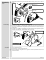
1
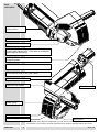
WCE 30
GB
Instruction for use
Please read and save these
instruction
D
Gebrauchsanleitung
F
Instruction d’utilisation
I
Istruzioni d’uso
DK
Brugsanvisning
N
Bruksanvisning
S
Bruksanvisning
Bitte lesen und aufbewahren
Prière de lire et de conserver
Vær venlight at læse og opbevare
Vennligst les og ta godt vare på
denne informasjonen
Var god läs och tag tillvara dessa
instruktioner
Si prega di leggere le istruzioni e
di conservarle
FIN
Käyttöohje
E
Instrucciones de uso
TR
Kullan∂m k∂lavuzu
P
Instruções de serviço
NL
Lea y conserve estas
instricciones por favor
Por favor leia e conserve em seu
poder
Gebruiksaanwijzing
Lees en let goed op deze advizen
RUS
Lue ja säilytö
Lütfen okuyun ve saklay∂n
Инструкция по
эксплуатации
Пожалуйста, прочтите и
сохраните данную инструкцию
a
(mm)
b
(mm)
c
(mm) m/sec
125
150
2,5
2,5
22,2
22,2
80
80
125
150
2,5
2,5
22,2
22,2
80
80
WCE
30
Id.-No. 4932-
a
c
b
•
•
•
•
•
3346 76
3671 27
•
3346 77
3671 26
•
3671 99
•
3627 78
•
3347 04
•
3627 77
•
3628 07
•
3293 97
Accessory ■ Zubehör ■ Accessoire ■ Accessorio ■ Accesorio ■ Acessório ■ Toebehoren ■ Tilbehør ■ Tilbehör ■ Lisälaite ■ Aksesuar ■ Принадлежности ■
You demand the best and buy quality - quality provided by Milwaukee. We have built
for you a reliable and lasting tool. Working effectively and without endangering your
health is only possible if this instruction for use is read carefully before first using the
tool. We want to satisfy our customers and would like you to buy again Electric
Power Tools from Milwaukee.
Introduction
Technical Data
Safety advice
Type
Nominal power (W)
No-load speed (min-1)
Grinding disk diameter (mm)
Cutting depth (mm)
Cutting width (mm)
with standard set of distance plates
with special set of distance plates
Weight (kg)
Smooth start
No-load speed limiter
Overload protection
Infinitely variable cutting width
adjustment
(110 V) WCE 30
1300
9500
125
8-30
WCE 30
1500
9500
125
8-30
15-26
6-14
3.8
15-26
6-14
3.8
•
•
•
•
•
•
•
•
■ Please pay attention to the safety instructions in the attached leaflet!
■ Do not pierce the motor housing as this could damage the double insulation (use
adhesives).
■ Always pull the plug from the mains before making any settings or carrying out maintenance.
■ Only plug-in when machine is switched off.
■ Keep mains lead clear from working range of the machine. Always lead the cable
away behind you.
■ Before use check machine, cable, and plug for any damages or material fatigue. Repairs should only be carried out by authorised service agents.
■ After switching off, the machine will not be idle immediately. (After-running of the
work spindle.) Allow the machine to come to a stop before putting down.
■ Never reach into the danger area of the machine when it is running.
■ Always wear safety goggles and ear protectors when working with this machine. It
is further recommended to wear safety gloves, apron, as well as sturdy non-slipping
shoes.
■ Always keep a safe footing and hold machine with both hands.
■ Always use the protective shields on the machine.
■ Always use the additional handle.
■ Only use the machine with a suitable dust-remover!
■ Immediately switch off the machine in case of considerable vibrations or if other malfunctions occur. Check the machine in order to find out the cause.
■ Only use and store diamond cutting discs according to the manufacturer's instructions.
■ Only use sharpened and flawless diamond cutting discs. Immediately exchange
bent or cracked diamond cutting discs. Carry out a test run without load for at least
30 seconds.
■ Only use tools whose permitted speed is at least as high as the highest no-load
speed of the machine.
ENGLISH
3
WCE 30
■ Pay attention to the dimensions of the cutting discs. The diameter of the centre hole
must fit the flange without play. Do not use any reduction pieces or adapters.
■ Only use the machine for dry cutting in stone.
■ Mind hidden electric lines, gas and water pipes. Check your working area, e.g. with
a metal detector.
Measured
sound value
Measured values determined according to EN 50 144.
Typically the A-weighted noise levels of the tool are:
Sound pressure level = 86 dB (A).
Sound power level =
99 dB (A).
Wear ear protectors!
Typically the hand-arm vibration is below 2.5 m/s2.
Measured
vibration value
Usage
The wall-chaser machine cuts slots for cables and pipes (masonry grooves) in any
kind of brickwork with two diamond cutting discs running parallel to each other.
The infinitely variable cutting width adjustment has the advantage that if the cutting
width was set correctly, the pipes or similar fit the slot exactly. They do not have to
be additionally secured with nails etc. against falling out.
Do not use this product in any other way as stated for normal use.
Mains
connection
Connect only to a single-phase AC current supply and only to the mains voltage
specified on the rating plate. Connection to sockets without earth protection is
possible as the appliance features protective insulation to DIN 57 740/ VDE 0740
and CEE 20. Radio suppression complies with the European standard EN 55014.
When fitting the plug, make sure that the brown (live) wire of this appliance is
connected to the plug terminal marked L or coloured red, and the blue (neutral) wire
of this appliance is connected to the plug terminal marked N or coloured black.
Under no circumstances must the wires of this appliance be connected to the earth
terminal of the plug marked either E, with the earth symbol, or coloured green or
green/yellow.
Electronics
The speed of rotation is adjusted electronically when the load increases.
In case of a longer overload period the speed is decreased electronically. The machine continues to run slowly to cool down the motor coil. After switching off and on
the machine can be used at rated load.
The duration of cooling-down period depends on the grade of overload.
Under the effect of extreme electromagnetic interferences from the outside, temporary variations in the speed of rotation could arise in particular cases.
Smooth start
ENGLISH
The electronic smooth start will prolong the life of both the motor and the gears.
Therefore do not run the machine under load for 2 sec. after switching on.
4
WCE 30
Brief
description
On/Off switch with
locking device
Spindle lock
Direction of rotation arrow
Infinitely variable cutting width adjustment 15-26 mm.
Cutting width adjustment 6-14 mm with set of distance
plates (special accessory).
Infinitely variable cutting depth adjustment with movable
supporting table.
No-load speed limit for low-noise operation
Electronic speed adjustment ensures constant speed
even when the load on the motor varies.
Suction channel/Handle
Additional side handle
Suction adapter
Depth gauge
Suction cover
Protective cap
Working tool
Modifications: Text, diagrams and data are correct at the time of printing. In the interest of continuous
improvement of our products, technical specifications are subject to alteration without prior notice.
ENGLISH
5
WCE 30
Switching on: Push the sliding switch forward. To lock, depress the front part of the
switch.
Switching on
and off
1
2
Switching off: To unlock, depress the back
part of the sliding switch. The switch will automatically move back to “O”.
Dust extraction
ENGLISH
Only use the machine with a suitable dust-remover!
Insert the suction hose connector into the
adapter until it sits firmly. Connect the other
end of the suction hose to a vacuum cleaner
which is suited for dust extraction.
6
WCE 30
Always disconnect the plug from the socket before carrying out any work on the machine.
Exchanging the
diamond cutting
discs
Spanntec-nut
Round nut with drilled holes
in one face
Disassembly
1. Loosen the screws and remove the protective cover.
2. Lock the work spindle by depressing the spindle lock. Open the round nut of the upper cutting disc with aid of a pin-type face spanner and remove it. Remove the upper
cutting disc.
3. Lock the work spindle by depressing the spindle lock. Remove the Spanntec-spindle
with aid of the Allen key and remove the back cutting disc.
Spanntec-spindle
Tension flange
Assembly
1. Insert the tension flange.
2. Assemble the machine in reverse order.
☞
ENGLISH
7
Arrow on diamond cutting discs must agree with arrow on protective hood cover-direction of rotation.
WCE 30
Loosen the Allen screw of the Spanntec-nut
with the T-key (to stop).
Setting the
cutting width
Move the outer diamond cutting disc to the
required cutting width.
Spanntec
To lock it in the required position fasten the
Allen screw tightly.
Set of distance
plates (special
accessory)
1. Loosen the screw and open and remove the
protective cover.
2. Lock the work spindle by depressing the
spindle lock. Open the round nut of the upper
cutting disc with aid of a pin-type face spanner and remove it. Remove the upper cutting
disc.
3. Loosen the Allen screw with the T-key and
remove the Spanntec-nut.
4. Fit the diamond cutting disc to the collar of
the reduction ring and push it together with
the distance plates over the Spanntec-spindle. The collar of the reduction ring must face
outside.
Spanntecspindle
Spacing
washers
Reduction ring
Spanntec-nut
Round nut with
drilled holes in one
face
5. Screw down the Spanntec nut on the Spanntec-spindle and the round nut on the Spanntec-nut.
6. Fasten the Spanntec-nut with aid of the spanner (to steady depress the spindle
lock).
☞
The number of the distance plates between the diamond cutting discs determines
the cutting width. Without distance plates (only with reduction ring) the cutting width
is 6 mm. The set of distance plates contains the following distance plates:
1 Spacing washer
2 Spacing washers
1 Spacing washer
☞
1 mm
2 mm
3 mm
Arrow on diamond cutting discs must agree with arrow on protective hood cover-direction of rotation.
7. Reassemble the tool (see above).
Setting the
cutting depth
Loosen the wing nut and set the depth gauge
to the required depth. Loosen the wing nut
and set the depth gauge to the required
depth.
☞
☞
ENGLISH
8
The cutting depth gets less as the diamond
cutting discs wear down.
In order to prevent edges from the remaining
cut strip breaking out, set the cutting depth
slightly deeper.
WCE 30
Only use the machine for dry cutting in stone.
Advices for
operation
Mind hidden electric lines, gas and water pipes. Check your working area, e.g. with
a metal detector.
1. Pre-select the cutting depth and width.
2. Switch the machine on.
3. Set the machine with the front edge of the
cutting support touching the masonry and
lower it gently in until the cutting support lies
flush.
4. Cut the masonry groove by pulling the machine towards you (in direction of arrow in illustration), guiding the machine with both
hands. Only cut straight lines radii are not
possible.
☞
☞
Always use the additional handle.
When cutting hard material, swing the machine slightly to and fro in the cut then the
diamond cutting discs stay sharper longer.
5. When you get to the end of the groove you
are cutting, lift the machine out first and then
switch off.
After switching off, the machine will not be
idle immediately. (After-running of the work
spindle.) Allow the machine to come to a stop before putting down.
The cutting discs get very hot when in use. Do not touch them before they have
cooled down.
6. Put the machine down and break out the remaining strip with the paring-out tool.
Tips
The infinitely variable cutting width adjustment has the advantage that if the cutting
width was set correctly, the pipes or similar fit the slot exactly. They do not have to
be additionally secured with nails etc. against falling out.
Cutting hard materials, especially concrete, requires a very high engine performance. If the feed rate is too high the load-rate motor protection slows the motor
down.
We recommend: When having to cut into the material very deeply, cut in two steps.
First, cut about half the required depth, and in a second step cut the full depth.
Blunt diamond cutting discs are recognisable by the large number of sparks that fly
during work, and can be resharpened by making a number of cuts in abrasive material (e.g. plaster).
Service
Keep the machine and the ventilation slots clean.
Use only Milwaukee accessories and spare parts. Should components which have
not been described need to be exchanged please contact one of our Milwaukee
service agents (see our list of guarantee/service addresses)
If needed, an exploded view of the tool can be ordered. Please state the ten-digit
No. as well as the machine type printed on the label and order the drawing at your
local service agents or directly at:
Atlas Copco Electric Tools GmbH, Postfach 320, D-71361 Winnenden.
Accessories
ENGLISH
Please refer to page 2 for range of accessories. Further accessories with part numbers are shown in our catalogues.
9
WCE 30