1
2004 Owners Manual
SERVICE
1. Service
2. Floor Plan and Features
3. Vehicle Operation
4. Chinook Cube Slide RoomTM
5. Automatic AirbagslJacks
5. Electrical System
6. Fresh Water System
7. Waste Water System
8. LP Gas System
9. Maintenance
10. Specifications
11. Frequently Asked Questions
SERVICE
Service is important to you ..., and it is equally important to us. When you buy a
Chinook, you can expect years of carefree service with regular but minimal maintenance. Our
reputation has been built on that premise.
DOUBLE SERVICE BACKUP
Your Chinook dealer's service department will promptly handle any operational difficulty
you may have with your motorhome. If such a problem is not resolved to your complete
satisfaction, please take these steps:
I.Discuss the problem with the general manager or owner of your dealership. Give him
the opportunity to work with his service crew in solving it.
2. If the difficulty cannot be resolved to your satisfaction by your local dealer, contact the
service manager at the Chinook factory for assistance by calling:
1-800-552-8886
This double service backup is your best assurance that you have made the right decision in
choosing a Chinook.
YOUR DEALER'S RESPONSIBILITIES
Your Chinook dealer has thoroughly inspected your motorhome, resetting the lighting,
plumbing, water and heating systems for any malfunctions that may have occurred during
shipment from the factory. All appliances are checked by the dealer at the time of purchase.
He is obligated to explain and demonstrate the operation of your equipment and accessories,
answer questions and make minor adjustments. For further instructions on operation,
maintenance and warranties please refer to the individual manuals or instruction sheets
provided in your owner's packet.
-
If you should require service and replacement of defective equipment, make your
request directly to the manufacturer of the appliance or accessory involved. In contacting any
manufacturer, dealer or Chinook factory for service or information, be sure to include all the
following:
1. Date of purchase along with stock or vehicle identification number.
2. Serial and model number and a complete description of the product.
3. Detailed explanation of the difficulty you are having.
Replacement parts should be purchased through the manufacturer or supplier or
through your local dealer or supply store. If you have difficulty obtaining parts or service,
contact the Chinook factory for assistance.
REGISTER YOUR WARRANTY TODAY!
Your first responsibility at the time of delivery is to register your warranty, so mail in your
completed warranty registration card today. Only by filling out and submitting your registration
card can you be assured of the guarantees it provides. This card is for your protection as a
consumer; use it now!
Rev. 1-1
2
SERVICE
Remember, warranties do not cover normal maintenance service or adjustments which may
become necessary through normal extended use. That is why. afteruiy have met your first
obligation by submitting your warranty card, you must be prepared for an on-going
responsibility: preventive maintenance.
You have just bought the finest mini-motorhome in the world, and we want you to enjoy
every mile of it. All you have to do is rely on the tips and recommendations offered on the
following pages.
m
SHELL WARRANTY:
Our unique fiberglass, one piece molded shell is covered by a lifetime warranty to the
original owner. Loss of time, inconvenience, loss of use of motorhome, towing charges, rental
cars or other consequential damages are not covered by this warranty.
WHAT IS COVERED:
FACTORY DEFECTS ONLY - Factory defects will be determined by the Chinook
Engineering Department or an authorized representative of Chinook.
WHAT IS NOT COVERED:
1.
2.
3.
4.
5.
6.
7.
GEL COAT FRACTURES
GEL COAT DISCOLORATION
ROCK CHIPS
COLLISION DAMAGE
VANDALISM
NATURAL DISASTER DAMAGE
FASTENER POINT DAMAGE FROM NON-FACTORY INSTALLED
COMPONENTS
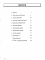
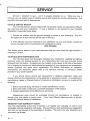
FLOOR PLANS & FEATURES
GENERAL
Your Chinook motorhome is a compact, yet versatile, recreational vehicle loaded with
features designed for your comfort and convenience. To help you in locating and identifying
these features see the drawing on pages 5-8. Note that, while only the dinette option is shown, all
other components are identical among the three floor plan options (dinette, club and twin-bed).
Also, many of the features shown are options and may or may not be in your motorhome.
SYSTEMS MONITOR PANEL
At the press of a button you can determine the fluid levels in the fresh water tank, waste
water holding tanks, and LP gas tank from the systems monitor panel located above the closet
door (refer to the chapter on the waste water system for false tank readings). This panel also
includes the monitoring of the charge level of the coach batteries.
APPLIANCES
Your motorhome is loaded with top-of-the-line, name brand appliances. Operating
instructions and specifications for these appliances can be found in your owner's packet.
Appliance specifications are also listed on a label located on the inside of the closet door.
COACH BATTERY SYSTEM
All models of the Chinook motorhome come with a state-of-the-art battery system that
includes a Low Voltage Disconnect (LVD) and a "Smart" solenoid. With the LVD, accidental
drainage of your coach batteries will be minimized, if not eliminated entirely. With the "Smart"
solenoid, you will be able to charge your coach batteries as well as your vehicle battery, while
eliminating the possibility of accidentally draining your vehicle battery through the coach batteries
or vice-versa. Refer to page 20 on the electrical system for more information.
TOWING PACKAGE
A towing package is included as a standard feature on the Chinook Motor home (Rated @
5000 Ibs. with a 500 Ib. Tongue weight). This includes the trailer hitch as well as tail light
electrical hook-ups. The tail light electrical hook-ups can be found on the extreme rear of the
driver's side frame rail. Review the section "Loading and Towing" in the next chapter for safe
towing procedures.
CLOCK
The clock in your motorhome is operated off a battery, which should last approximately one
year. To reset the clock, first remove the clock from the cabinet by twisting it counter-clock-wise,
and then turn adjustment knob on the back.
L
Rev. 1-1
I
L.
---
.. .
Rev. 1-1
- -
-
:
-
.
FLOOR PLANS & FEATURES
Rev. 1-1
FLOOR PLANS & FEATURES
Rev. 1-1
FLOOR PLANS & FEATURES
Rev. 1-1
8
FLOOR PLANS & FEATURES
FLOOR PLANS & FEATURES
SLEEPING ACCOMMODATIONS
Sleeping accommodations vary from model type and floor plan and may even be unique to your
motorhome, if you ordered it with special options. The sofa-bed, offered in the Club and Dinette
floor plans, is folded out to the sleeping position as shown below. On Dinette floor plans, the
sofa-bed forms a larger bed with the dinette seats when they are configured with the dinette table
lowered as shown below.
SOFA-BED
TO CONVERT SOFA-BED TO SLEEPING POSITION PULL U P AND OUT ON FRONT
BOTTOU EDGE OF SOFA AS INDICATED BY ARROWS.
DINETTE-BED
STEP 3.
LOWER T A B U TOP TO SUPPORT
CLEATS ON SEATS BY ROTATING
BRASS HINGE ASSEMBLY ABOUT
LOWER WALL SUPPORT.
STEP 2.
TILT TABLE TOP DOWN
TO DISENGAGE FROM
SUPPORT CLEAT
STEP 4.
PLACE SEAT BACK CUSHIONS
FROM BOTH SEATS ONTO THE
TABLE TOP TO FORM A LEVEL
SLEEPING SURFACE.
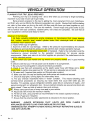
VEHICLE OPERA TlON
PLANNING YOUR TRIP, BEING PREPARED
Planning your trip is an exciting time - and a time when you are likely to forget something
last minirt~!
n ish tn net
..imnnrtant
. .r - . --. .. in
... vniir
--. .--.
a-- reariv
'---J.
Being properly prepared is the key to getting the most enjoyment from your motorhome,
and that's why we are offering the following suggestions as a guide. Review them before starting
out, refer to them when you are on the road, and then note the items you have forgotten so your
next trip will be even more fun. Plan your trip carefully. Consult maps and guide books so you
will be familiar with road conditions, roadside parks, rest areas and campsites. Be sure that all
your equipment is serviced and ready for travel.
. . , a ,
L
o w . -
. - - 9 .
.w
Check all of the following:
1. All fluids, including motorhome engine crankcase oil, transmission fluid, power steering
fluid, radiator reservoir level, master cylinder brake fluid, electrolyte level of batteries,
windshield water reservoir level.
2. Inspect wheel lugs for tightness.
3. Examine all tires for road damage. Inflate to the pressure recommended by the chassis
manufacturer and note that this pressure is for cold tires (see chassis operator's manual).
4. Check oil level in the generator power plant (if installed). Refer to the instructions and the
maintenance manual provided by the generator manufacturer for pre-use service
requirements. Make sure extra oil and other supplies are provided if the motorhome is to be
used for extended periods.
5. Make certain your jack handle and lug wrench are properly stowed and in good working
order.
6. Check to see that your 110-volt power cord is stowed in its compartment.
7. Be sure your fire extinguisher is secured and easily accessible.
8. Check to see that such accessories as the plastic sewer hose with fittings and a water
supply hose (a garden hose approved for 125 psi service is adequate) are on board.
9. Fill water tank, if required (see section on Chinook water system).
10. Make sure drain line cap and holding tank knife valves are closed and secured.
11. Check all stop lights, running lights and other safety items.
12. Put your Chinook motorhome items in "travel" condition. This means following such
common-sense procedures as securing any loose items that could shift while you are
traveling. For example, secure refrigerator contents- place lids on containers of liquids - and
secure locking latch on refrigerator door. Be sure cabinet contents are secured and doors are
tightly closed. Close and lock all exterior doors and windows.
13. Always carry spare fuses of every size used in your vehicle.
14. Adjust side view mirrors for maximum visibility.
15. Fill the fuel tank, using only the fuel recommended in the chassis operator's manual.
16. Fill the LP-gas tank if required.
17. Ensure that the antenna and/or satellite dish is retracted to the travel position.
WARNING!
ALWAYS EXTINGUISH PILOT LIGHTS AND OPEN FLAMES ON
APPLIANCES BEFORE FILLING YOUR GASOLINE OR LPG TANK.
WARNING DO NOT ATTEMPT TO MOVE VEHICLE WITHOUT RETRACTING SLIDE (S)
AND AUTO LEVELERS
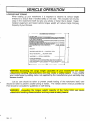
VEHICLE OPERA TlON
LOADING AND TOWING
When loading up your motorhome it is important to observe its various weight
limitations to ensure that it handles safely on the road. This includes not only the
cargo in the motorhome itself but also any vehicle or trailer that is towed. Dealer
installed equipment and towed vehicle tongue weight will reduce Cargo Carrying
Capacity of your Chinook.
MOTORHOME \kTlGlll IHFORLIATIOW
1
I1
1=
MINUS Ff4ESH WATER W f l t l l l OFHltillS LP C I S WEIGHT O
!&);US SCWR O F
GALLOIlS8 11 3 LBltAL
F GALLONS @ 4 5 L W L L
-PLRSOIIS O 154 L0,PERSOH
CCC FOR TIIIS MOTORIIOME'
_._
-
I
1
I
I
I I
I II
WARNING: Exceeding the cargo weight capacities of your motorhome can cause
undesirable handling characteristics and may create a safety hazard. If you modify
your motorhome b y adding racks not supplied by the manufacturer your warranty may
become invalid.
L
Just as care should be taken to prevent unsafe loading of the motorhome itself, care
should be taken to prevent unsafe towing of trailers. The vehicle owner's manual provided by
Ford should be consulted for guidelines on safe towing.
WARNING: Exceeding the tongue weight capacity of the trailer hitch can cause
undesirable handling characteristics and may create a safety hazard.
Rev. 1-1
VEHICLE OPERA TlON
STARTING UP AND READY TO LEAVE
With your preparation and final checkouts completed, you're ready to leave. However,
note the following before leaving:
MAKE DOUBLE SURE SLlDES ARE RETRACTED AND LEVELING JACKS ARE UP!!
1. When starting, warming up and operating your engine, you'll get the best results and the
performance you want by following the instructions in your chassis operator's manual.
2. Seat belts are a vital safety feature in your Chinook motorhome. All seat belts should be
fastened while your motorhome is in motion. Seats not equipped with belts should not be
occupied while the vehicle is in motion.
AT LAST, YOU'RE ON THE ROAD!
Once you've become accustomed to the feel of the controls and can accurately gauge
distances and the length and width of the vehicle, your Chinook motorhome is like driving your
family car. It's easy to handle, maneuver and park. However, be cautious when maneuvering so
you allow for the extra length and width of the motorhome. Check your side view mirrors
frequently for approaching traffic from the rear.
When on the road, remember that higher speeds may result in a sharp increase in fuel
consumption. Always allow for the extra height of your Chinook. It's approximately 10' without
roof air conditioning and 10%' with it. Avoid low overhead clearance areas such as low roofs at
service stations. This is especially important as you drive with the overhead vent open or if you
have a roof storage pod or air conditioner. When parking, remember that the rear wheels are
wider than the motorhome. Also, when parking on an incline, your front wheels should be turned
into the curb in the direction of the roll as an aid to your parking brake.
rn
Chanqinq a Tire
See your chassis operator's manual for tire changing instructions. Your fully loaded
motorhome is very heavy, and the lug nuts usually are set with a power torque wrench which
makes them extremely difficult to remove. Obtain road service (see Ford's service number below)
whenever possible, and only attempt to change tires yourself when it is an emergency situation.
FORD MOTOR HOME OWNERS SERVICE LOCATOR HOTLINE NUMBER
This service provides 24-hour, 7-day-a-week assistance in contacting a dealership, arranging a
service appointment and providing a dealership contact person name. This service can also
assist in locating towing service, if needed.
L
Rev. 1-1
VEHICLE OPERA TlON
WARNING: Loosening the rear lug nuts may release both outside and inside wheels.
Do not attempt to remove lugs without having your jack i n position to absorb the full
weight of the motorhome.
Fire and Life Safety
Your motorhome is equipped with the following pieces of safety equipment that should be
checked prior to your departure:
1. A properly rated fire extinguisher located just inside next to the coach door. Check your
extinguisher on a regular basis for proper charge and make sure it is operabie.
2. A CO (carbon monoxide) monitor located above the closet door.
3. An LP gas detector located at the bottom of the galley cabinet.
4. A smoke detector located on the ceiling near the bathltoilet cabinet.
Emerqencv Exits
The main coach entrance door is designated as the main emergency exit. The passenger door is
designated for use as an alternate emergency exit. These exits should be kept unobstructed and
free to open completely.
Emerqency Start
In the event that the vehicle (chassis) battery is drained, you can tap into the coach batteries with
the "Vehicle Boost Start" switch, located above the driver's seat to start the engine. Note that this
switch needs to be depressed while simultaneously turning the ignition key on.
Auxiliaw Liqhts (Optional)
Turning on driving lights is accomplished as follows:
1. To turn on driving lights, the switch should be in the "Driving Lights" position; this switch
operates independently from the headlamps (Located in the overhead switch cluster).
CAUTION: Traffic rules in many states require that fog lights only be used when the
headlamps are set in the low beam position and that driving lights only be used with
the headlamps set in the high-beam position.
L
Rev. 1- 1
CHINOOK CUBETMSLIDEROOM
Slide-out Operation
Slide Room Extend
1. Set Emergency Brake.
2. Insert key in slide panel and turn to the on position.
3. Wait until the amber light is on constantly (It flashes while the air seal is deflating)
rn
4. When the amber light is on constantly press and hold the button in the extend position (This
will retract the travel locks and extend the room)
5. Continue holding the button in the extend position until the room is fully extended (NOTE: DO
NOT RUN THE ROOM PART OF THE WAY OUT AND ATTEMPT TO RETRACT IT, THIS MAY
CAUSE THE SYSTEM TO FAIL)
6. Release the button and turn off the key (This will re-inflate the air seal)
Slide Room Retract
1. Set Emergency Brake.
2. Insert key in slide panel and turn to the on position.
3. Wait until the amber light is on constantly (It flashes while the air seal is deflating)
4. When the amber light is on constantly press and hold the button in the retract position.
L
5. Continue holding the button in the retract position until the room is fully retracted and the travel
locks have fully extended and the red pump indicator light turns off. (NOTE: DO NOT RUN THE
ROOM PART OF THE WAY IN AND ATTEMPT TO EXTEND IT BACK OUT, THIS MAY CAUSE
THE SYSTEM TO FAIL)
6. Turn the key to the off position (This will re-inflate the air seal)
Slide-out Manual Retraction
If for any reason the slide or auto levelers will not retract, DO NOT ATTEMPT TO FIX THEM
YOURSELF. Immediately call the Chinook Service Department at 1-800-552-8886. They will
walk you through the Manual Retraction Procedure.
L
Rev. 1-1
CHINOOK CUBETMSLIDEROOM
9
Chinook CubeTMComponents/Trou bleshooting
-
The following is a list of the major components of the hydraulic system in your Chinook
motorhome. This list should give you a better understanding of how your Chinook CubeTMworks.
(See page 16) If your motorhome exhibits any malfunction in these components please call the
Chinook Service Department immediately at 1-800-552-8886, or if it is after business hours call
Jason Schmidt at 509-949-0173 or Mike Undenvood at 509-930-2072
CAN (Controlled Area Network). System of computer operated switches and relays.
Connects all components of Auto Leveling Jacks, User Controls, and Slide operating
system. Located under the motorhome (in the drivers side front storage bin)
Air Seal. Fills area between Chinook CubeTMand the main fiberglass body. lnflates any
time the key to the room slide system is in the off position, sealing out weather or water.
Deflates to allow the room to slide in or out.
Air Compressor and Tank. lnflates the Air Seal and provides air for the Automatic Ride
Leveling Airbag System.
-
U.,rl-r..l:r. D . m m . . r
-r\rl D l r r l r - , m : r
nyuIauII~
r u I I I p a l l u ntsatzl VUII.
D v n ~ t i A n ethn m n n t t n r / n i l m r n e e a n r n \
r
IUVIUG~
LIIG
+n-nt,n
puvvc~\ V I I p ~ c a a u i c LV
j
IIIUVC
+hn Phinnnb
LIIC
ulIIIIuun
CubeTMin and out, as well as level the jacks. Located under the motorhome (in the drivers
side front storage bin)
User Interface. Allows the user (you) to operate the Chinook CubeTMsystem, and monitor
the status of the system. Located on the front drivers side overhead panel, (just above the
drivers seat.)
Room Locks. Locks the Chinook Cuben+Iin the "in" position while not in use, automatically
retract to allow the slide out procedure. Located on the top side of the room. Mounts to the
motorhome.
m
Hall Effect Sensor. Determines the position of the Room Locks to determine whether or
not they are deployed (locked) or retracted (unlocked). Located next to Room Locks on the
upper side of the Chinook CubeTMSlide Room.
Room In Sensor. Located on the Room Locks, detects the room in the "In" position.
Room Out Sensor. Located on the hydraulic ram (under slide room) detects the room in
C, ,I1
-,
,b
l u l l UUL pUSILIuI I.
L
Rev. 1-1
m
I
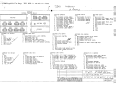
AUTOMA TIC LEVELING JACKS/AIRBAGS
Leveling Components
Your Chinook motorhome comes standard with two leveling systems. One works when the vehicle
is in motion, one when it is parked.
AIRBAGS
While in motion your Chinook motorhome is kept level and rigid on the road by an Automatic
Airbag System. This system consists of the onboard air compressor, connective tubing, sensors,
controls and independent air bladders. These components work together to compensate for
uneven loads, heavy towing, and uneven road surfaces. (See page 18)
LEVELING JACKS
After you arrive at your destination there is a second leveling system, the Automatic Leveling Jack
System is comprised of four Hydraulic Self- Deploying Jacks each attached to the underside of
your Chinook frame. They work with the following components of the Chinook CubeTMslide
system. (See page 16)
CAN (Controlled Area Network). System of computer operated switches and relays.
Connects all components of Auto Leveling Jacks, User Controls, and Slide operating
system. Located under the motorhome (in the drivers side front storage bin)
Hydraulic Pump and Reservoir. Provides the power (oil pressure) to move the Chinook
CubeTMin and out, as well as level the jacks. Located under the motorhome (in the drivers
side front storage bin)
User Interface. Allows the user (you) to operate the Chinook CubeTMsystem, and monitor
the status of the system. Located on the front drivers side overhead panel, (just above the
drivers seat.)
When used in the proper manner this system will detect the list of the motorhome of as little as
118 inch from corner to corner and with a push of a button, brace and level the Chinook.
Levelinq Jack Operation
1.
2.
3.
4.
Turn on ignition
Set emergency brake
Press the onlauto button on leveling jack panel (This turns the system on)
Press the onlauto button on the leveling jack panel a second time (This kicks the jacks to the
down position)
5. Press the onlauto button a third time to auto level the coach or press the upldown, Ieftlright
arrows to manually level the coach.
6. To store the jacks press the off button and then press the store button.
7. NOTE: BE SURE TO STORE THE JACKS BEFORE ATTEMPTING TO DRIVE THE COACH.
I
I
AUTOMATIC LEVELING JACKS/AIRBAGS
I ILLUSTRATION
Rev. 1-1
1
I
ILLUSTRATION
2
I
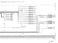
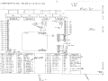
I
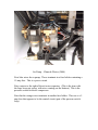
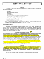
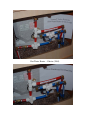
Air Pump – Chinook Glacier (2004)
Note blue wires above pump. These terminate in a fuse holder containing a
15 amp fuse. This is a power circuit.
Note canister to the right of the air/water separator. (This is the item with
the large brass nut on top, with wires coming out the bottom.) This is the
pressure switch for the air compressor.
Note that the orange wires terminate in another fuse holder. This one is a 5
amp fuse that appears to be the control circuit (part of the pressure switch
loop).
-
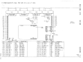
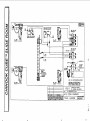
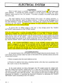
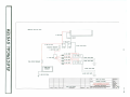
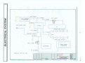
ELECTRICAL SYSTEM
GENERAL
The electrical system consists of IIOV AC and 12V DC appliances supplied by power
through a 100 amp converter and distribution panel. i t OV power is available either through a
1lOV receptacle provided at an RV park or campsite ("shore power") or through the optional
generator set as well as a I000 watt inverter. 12V power is available through the converter when
plugged into shore power or from two coach batteries. A schematic of the coach power system is
shown at the end of this chapter.
IIOV SYSTEM
Shore Power
The connection to IIOV shore power is made through a power cord located in the "servioe
center" on the driver's side towards the rear. To remove the cord, simply open the cover and pull
the cord out to the required length (26' is available). When leaving a campsite, be sure that the
cord is removed from the receptacle and stowed in its compartment. Failure to store it properly
could result in extensive damage.
Note: Shore power connections are rated for 30 amps Sewice.
2
CAUTION: Cord cap adapters should not be used, because this could result in
connecting the motorhome to an improperly rated source.
Generator Set
The optional generator set is located at the rear passenger side of the motorhome. The
manufacturer of this generator has provided complete operating instructions for the unit installed
by Chinook. These instructions, contained in the owner information and warranty package,
should be read completely before attempting to operate the generator. In addition to the switch
provided on the front panel of the Genset, all models have a generator start switch above the
wardrobe door and some models have a second optional generator start switch above the driver's
seat. The generator provides 4000 watts of power to charge your batteries as well as power your
IIOv and 12v appliances.
Breaker Panel
The 1 10V distribution panel is Iocated at the bottom of the wardrobe on Glacier models.
Breakers are used to protect the 110V electrical system. These circuit breakers do not reset
automatically and must be turned off, then returned to the *Onwposition. Continued tripping of the
breakers indicates an electrical problem that should be checked by a service technician. All
duplex outlets are GFCI protected by the GFCI outiet located just inside the side entry door.
There are dual buss panefs, one for shore power, and the other for the inverter.
Automatic Transfer Switch
An autarnatic transfer switch, located in the wardrube, senses which source of 110V power
is in use (shore power or generator) and will switch to that source. However, if both the generator
and shore power happen to be on at the same time, the generator will take priority- The owner's
manual for the generator should be reviewed for further information.
Rev. 1-1
ELECTRICAL SYSTEM
Appliances
110V power is used to run the following appliances and components (see 110V system at
the end of this section)
1. Converter
2. Microwave (run with inverter)
3. Refrigerator
4. Air Conditioner
5. GFI protected 110V Receptacles for portable appliances
6. Digital Satellite System (DSS) receiver (optional)
7. "Nu-Heat" floor heating pad (optional)
8. Television (s) (run with inverter)
9. Coach stereo system (run with inverter)
NOTE: The microwave and air conditioner (and optional DSS) will only operate o n
IIOV, while the refrigerator will operate on I I O V , 12V or LPG.
12V SYSTEM (COACH)
Most of the appliances in the Chinook motorhome run off of 12V power. As noted in the
previous section, the two exceptions are the microwave and air conditioner, which will only run off
of I10V power. 12V power is supplied through the 100 amp power converter (running off of 110V
shore power or the generator) or through two coach batteries. Some auxiliary 12V power is also
supplied from the roof mounted solar panel.
2000 Watt Prosine Inverter1Converter
The inverter allows you to run some 110v AC appliances without being connected to shore power.
Inverters work by producing a 60 hertz sine wave able to safely power any 110V appliance.
Prosine inverters come with a monitor which will shut down the inverter when battery voltage
reaches 12V DC, or when it detects shore power. Using the inverter can be a very power intensive
process and should be used with discretion. The built-in power converter is required to convert
110V power to 12V power. When shore power is available or the generator is turned on, 12V
power is supplied through the power converter to all appliances including power to charge the
coach batteries. As noted earlier, the power converter is located in the bottom of the wardrobe.
The converter supplies 100 amps to the 12V system. It has 4 stages, and automatically switches
between bulk, absorption, float, and quick charging stages, as needed
Fuse Panel
Ail 12V circuits are protected with properly rated fuses or automatic reset circuit breakers.
There are three exterior circuit breakers. One breaker is a 200 amp panel for the slide pump, one
100 amp panel for the generator, and one 100 amp panel for the main power network. If the
breaker continues to trip, however, the system should be checked by a service technician to
determine the cause.
The main 12V converter circuits are protected by fuses located inside the converter.
L
Rev. 1-1
ELECTRICAL SYSTEM
Coach Batteries
When no shore power is available, 12V power is supplied through two 6-volt deep cycle
coach batteries. To activate the system (whether or not the engine is running), the "Coach
Batteries" switch must be in the "On" position. This switch is located in the switch cluster above
the driver's seat.
The coach batteries can be charged through shore power, the optional generator, or
through the vehicle alternator, when the engine is running. In order to run the 12V system off of
the coach batteries or charge the batteries from 110V power, the "COACH BATTERIES" switch
must be in the "ON" position. The green light labeled "IN USEICHARGING" will be lit when the
coach batteries are in use or being charged.
h
To ensure that no battery power is lost over a long storage period the "COACH
BATTERIES" switch should be in the "STORE" position.
When the vehicle engine is running, the coach batteries will be charged through the alternator,
regardless of whether the "COACH BATTERIES" switch is in the "ON" or "STORE" positions.
Note, that the "Smart" solenoid (located under the hood) prevents the vehicle battery from being
drained by the coach 12V DC system. However, should the vehicle battery become drained for
some other reason, the vehicle can be started using power from the coach batteries by activating
the "VEHICLE BOOST START" switch while simultaneously turning the ignition key on.
NOTE: If the "COACH BATTERIES" switch is i n the "STORE" position when shore
power i s plugged in, an alarm will be activated and the red light labeled "SWITCH TO
ON IF LIT" will be illuminated. In this situation, turn the switch to the "ON" position;
the alarm will stop and the red light will turn off. Following this procedure will ensure
that the coach batteries are charged when 110V AC power is available.
m
Low Voltaqe Disconnect
An important feature of the 12V system is the Low Voltage Disconnect (LVD) module. The
LVD module, which is located inside the coach on the bottom of the wardrobe cabinet, serves the
following two functions:
1) Warns occupants when the coach batteries are low.
2) Prevents the batteries from being completely drained, when they have accidentally been
left on and no one is in the motorhome.
As the coach batteries are being discharged, the LVD module senses the voltage level.
When the voltage level reaches a preset value of 11.5 volts, the LVD activates an audible alarm.
This alarm is a signal to the occupant that the LVD module will disconnect the coach batteries
from the distribution panel within 60 seconds. The occupant has the choice of letting the LVD
disconnect the batteries, or overriding the disconnect procedure by depressing the "COACH
BATTERIES" switch momentarily to the "ON" position.
Rev. 1- 1
21
ELECTRICAL SYSTEM
NOTE: Overriding the LVD will only provide an additional 60 seconds of 12V power,
after which the LVD wllf again disconnect the coach batteries.
The coach batteries are located in a separate compartment below the water heater and
just behind the driver's door. Because these batteries produce hydrogen gas when under a
charge, the battery compartment has a vent at the top of the back wall. The compartment also
has vent at the bottom in order to drain any liquid leaking from the batteries. Note that this
mmpartment is for the storage of the coach batteries only; storage of other items in this
compartment may block the vents or short out the batteries.
Hours of use between charging depends on the current draw (amps) of the appliances in
use and the length of time they are used.
12V (AUTOMOTIVE)
The following optional 12V appliances are powered off ofthe vehicle electrical system:
I.
Rear-view mirror
2. Power side mirrors
3. Driving lights or combination driving & fog lights.
The fuses for these items are located in a fuse block under the driver's side dash. Note that pre
wired ignition hot and constant hot taps are available in the Glacier depending on installed
options.
r CAUTION: FUSES FOR THE PIE-WIRED IGNITION HOT AND
CONSTANT HOT TAPS SHOULD BE SIZED AS INDICATED.
h
Rev. 1-1
ELECTRICAL SYSTEM
Rev. 1-1
ELECTRICAL SYSTEM
FRESH WATER SYSTEM
GENERAL
Fresh water is supplied either from the on-board fresh water tank or through a hook-up to
municipal water when available at a campsite.
FRESH WATER TANK
The fresh water tank is located under the sofa-bed (or twin bed) on the driver's side. In
order to draw water from the fresh water tank. the water pump switch must be turned on. The
water pump switch is on the monitor panel on the wardrobe cabinet. Once the switch is turned
on, the water pump will cycle whenever a faucet is turned on or the toilet is flushed.
NOTE: The water pump cycles by sensing a drop i n water pressure. Normally this
occurs only when a faucet is opened or the toilet i s flushed. If the water pump cycles
at any other time, this may be an indication of a leak i n the water lines, which should be
checked immediately.
The fresh water tank is filled through the water tank fill port located on the lower right
corner of the Chinook CubeTMslide room. The water pump switch should be turned off when the
water system is not in use or hooked up to city water.
CITY WATER
A direct connection may be made to a city water pressure system through an inlet fitting in
the "service center" on the driver's side of the motorhome. When using the city water hookup, it is
not necessary to operate the water pump. The city water inlet fitting contains a pressure regulator
limiting the system pressure to 125 psi. This prevents damage to the piping caused by
excessively high supply pressures such as those encountered at some campsites.
WATER HEATER
All models are provided with a hot water heater located under the range cabinet. As a
standard, the water heater on Chinook motorhomes runs off of LP gas only (with electric ignition).
The specifications of the water heater in your motorhome can be found in the operating
instructions in your owner's packet.
If desired, water to the water heater can be by-passed by changing the positions of the two
valves located in front of the water heater. The valve positions for flow through the water heater
and for by-passing the water heater are available from the Chinook Service Department at
1-800-552-8886.
OUTSIDE SHOWER
The outside shower is located in the "service center" on the driver's side. The shower head
with flexible hose can be removed by opening the access panel located just above the left rear
wheel well.
I
Rev. 1-1
FRESH WATER SYSTEM
DRAINING THE FRESH WATER SYSTEM
Periodically it is necessary to drain the fresh water system. This is done by opening the
water tank drain petcock valve and the hot and cold line petcock valves located inside the coach,
under the sofa, or twin bed, on the drivers side. Pump must be on to drain coach.
If your motorhome is used frequently, you can leave water in the tank. Keep it sweet by
adding a teaspoonful of soda to every fourth or fifth tank of water. For long periods of time
between use, drain the tank completely except for a teaspoonful of soda and two gallons of water.
When you are ready to use the unit again, refill the tank and drain completely, then refill with fresh
water.
L
WINTERIZING
To winterize the fresh water system, first drain the fresh water lines and tank. Next, add a
recommended solution to prevent freezing in traps and other water filled cavities in the drainage
system only.
WARNING: Do not use antifreezes other than those recommended for plastic pipe and
recreational vehicles.
WATER PUMP SERVICING
If the water pump needs to be serviced or replaced, there is a three-way valve located
between the water tank and the pump that should be shut off. This allows the removal of the
water pump without having to drain the water tank.
L
Rev. 1- 1
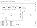
mCUM
INK
NOTE:
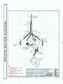
I . } WATER LINES ARE PEX 112" 1.D. AND
5/8" 0.0.
2.) INSTALLED PER W T E R 5 ANSI
A1 19.2 2002. € D m H
P
b
II
Hot Water Heater – Glacier (2004)
WASTE WATER SYSTEM
GENERAL
Two waste water holding tanks are installed on your motorhome. They are located under
the coach to the rear of the driver's side as shown in the Technical Drawing section. The "gray"
water tank holds waste water frcm the galley sink, shower sink and shower. The "black" water
tank holds waste from the toilet.
DRAINING THE WASTE HOLDING TANKS
When your holding tanks require emptying, follow these steps:
1. Locate an outlet where they may be drained. This may be a gas station which
has septic tank pumping facilities, a trailer park or a supply and service facility.
Guidebooks contain these locations.
2. Park next to the inlet where you will dump the waste.
3. Remove the flexible hose from its storage compartment. Make sure the drain
valves are closed, (T handles all the way in), remove the drainage cap, insert the
hose connector and tighten.
4. Insert the opposite end of the hose into the pump tank inlet.
5. Open the valves by pulling the T handles all the way out.
6. When the tanks are empty, close the valves and secure them. The system is
now completely drained and ready for use.
7. Utilize black tank flush each time tanks are emptied. (Located at left rear)
8. Return the flexible sewer hose to its storage tube and secure the cap.
NOTE: A false reading from the monitor panel indicating that a holding tank is full
even after it has been drained can occur (especially on the "black" water tank). This
i s usually caused by debris such as tissue paper lying across two or more probes
inside the tank resulting i n a short. This problem can be remedied by flushing the
tank until all debris i s cleared from the probes.
rn
CLEANING
From time to time add a gallon or two of water containing liquid detergent into the holding
tanks. The movement of the water and detergent when the vehicle is in motion will clean the
tanks. Use of a holding tank deodorant prevents excessive odor from the tanks. Several
products are generally available for this purpose.
WINTERIZING
After draining the waste water tanks, add a recommended solution to prevent freezing in
traps and other water filled cavities in the drainage system only.
WARNING: Do not use antifreezes other than those recommended for plastic pipe and
recreational vehicles.
b
Rev. 1-1
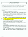
LP GAS SYSTEM
GENERAL
LP-gas is supplied to your appliances from a storage tank located under the motorhome
around the center of the couch. The high pressure of the storage tank is reduced to appliance
operating pressure by a two-stage regulator attached to the main supply valve. LP vapor passes
through this regulator to a steel pipe manifold and is then distributed to LP appliances. IN ORDER
TO USE THE PROPANE SYSTEM THE ELECTRIC SWITCH LOCATED ON THE PROPANE
TANK (ACCESS TO THE TANK IS AVAILABLE UNDER THE DRIVERS SIDE OF THE
COACH BEHIND THE SMALLEST DOOR) MUST BE IN THE "ON" POSITION. ALSO, IT IS
IMPORTANT WHEN NOT IN USE TO TURN THE PROPANE SWITCH BACK TO THE "OFF"
POSITION.
The following appliances operate on LP-gas:
1. Furnace
2. Water Heater
3. Rangeloven
4. Refrigerator (LP gas is an optional fuel source for the refrigerator, which can also run
on 12V or 1 1OV power).
5. Generator as supplied on Diesel models.
To assure safe, troublefree operation, read the manufacturer operating instructions for
each appliance completely before use. Each appliance manual can be found in the owner's
packet provided with your motorbome.
SAFETY
To ensure safe operation of your LP appliances, you should be aware of the following
warnings and warning labels:
WARNING: LP-Gas containers shall not be placed or stored inside the vehicle.
LP-Gas containers are equipped with safety devices that relieve excessive
pressure by discharging gas to the atmosphere. FAILURE TO COMPLY COULD
RESULT IN DEATH OR SERIOUS INJURY.
The following warning label has been located in the cooking area to remind the user to provide an
adequate supply of fresh air for combustion:
WARNING: IT IS NOT SAFE TO USE COOKING APPLIANCES FOR COMFORT
HEATING.
I
Cooking appliances need fresh air for safe operation. Before operation:
IOpen the overhead vent or turn on the exhaust fan, and
2. Open a window.
Rev. 1-1
LP GAS SYSTEM
Unlike homes, the amount of oxygen supply is limited due to the size of the recreational vehicle,
and proper ventilation when using the cooking appliance(s) will avoid the danger of asphyxiation.
It is especially important that cooking appliances not be used for comfort heating as the danger of
asphyxiation is greater when the appliance is used for long periods of time.
I WARNING: THE GAS PIPING SYSTEM IS DESIGNED FOR USE WITH LP-GAS
ONLY. DO NOT CONNECT NATURAL GAS TO THE SYSTEM.
r
Unlike natural gas used in homes, LP-gas is heavier than air. This means that if a leak
should occur in the system the escaping gas will seek the lowest level in a contained area.
Simply opening windows wilt not lessen the danger of explosion. If a leak is suspected, be sure to
open all windows, doors, cupboards and drawers to allow any accumulated gas to flow to the
exterior.
A warning label has been focated near the LP-Gas container- This label reads:
W A R N I N G : DO NOT FILL CONTAINER(S) TO MORE THAN 80 PERCENT OF
CAPACITY FAILURE TO COMPLY COULD RESULT IN DEATH OR SERIOUS INJURY.
Overfilling the LP-Gas container can result in uncontrolled gas flow, which can cause fire or
explosion. A properly fiIled container will contain approximately 80 percent of its volume as liquid
LP-Gas.
WARNING: Do not use fuel-burning equipment, including wood and charcoal
grills and stoves inside the motorhome. The use of this equipment inside the motorhome
may cause fires or asphyxiation.
, WARNING:
Do not bring or store LP-Gas containers, gasoline, or other
flammable liquids inside the vehicle because a fire or expIosion may result.
r
The following label has been placed in the vehicle near the range area:
L
c WARNING IF YOU SMELL GAS:
1. Extinguish any open flames, pilot lights, and all smoking materials.
2. Do not touch electrical switches.
3. Shut ofF the gas supply at the tank valve(s) or gas supply, connection.
4. Open doors and other ventilating openings.
5. Leave the area until odor dears.
6. Have the gas systems cheeked and leakage source corrected before using again.
LP GAS SYSTEM
LP-Gas regulators must always be installed with the diaphragm vent facing downward.
Regulators that are not in compartments have been equipped with a protective cover. Make sure
that the regulator vent faces downward and that the cover is kepi in place to minimize vent
blockage that could result in excessive gas pressure causing fire or explosion.
OPERATION AND MAlNTENANCE
Below are some additional procedures you should follow in the operation and maintenance of the
LPG system:
1. Familiarize yourself with the distinctive odor of LP-gas.
2. Check the entire system for possible leaks and missing or damaged parts before and
after each trip, when filling the storage tank and any time you suspect trouble. Your
Chinook motorhome is designed so all joints and connections in its LP-gas system are
accessible for inspection, You should check these connections periodically by brushing a
solution of water and liquid detergent on the frttings under pressure and watching for
bubbles an indication of escaping gas.
-
8
WARNING: Do not use a lighted match or similar device to detect LPgas leaks.
3. If a leak is suspected, immediately turn off the main service valve on the tank and ask
your LP-gas dealer to check the system.
4, In an emergency, the tank senrice valve must be readily accessible. Never attach a lock
or device requiring a key, special tools or knowledge to open or close this valve.
5.When the LPgas system is not in use, turn off the gas supply at the tank.
6. Never use a wrench to tighten the tank senrice valve. It is designed to be dosed leak
tight by hand, If a wrench is required to close or open the valve, it must be repaired or
replaced.
7. Read and observe the tank manufacturer's instructions. They will explain the operation
of all tank controls.
8. Do not tamper with LP-gas piping System, pressure regulator or appliances. Exercise
caution when drilling holes or attaching objects to walls or floor area.
9. Be sure appliance, plumbing and outside vents are free of obstructions when operating
any LP-gas appliance.
10. The LPgas tank should be filled only by qualified personnel at an LPqas dealer
senrice station. Note that tho LPgas tanks are initially pressurized with air which
must be bled off before the tank can be filled.
LP GAS SYSTEM
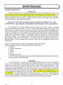
MAINTENANCE
GENERAL MAINTENANCE
Exterior Care
Care for the exterior of your motorhome as you would for an automobile or boat finish. The
Chinook surface may be cleaned using car shampoo, mild detergents or household cleaners - but
be sure to check the list which follows. Strong soaps and abrasive cleaners should not be used.
Dirt or grime that has been ground into surfaces is easily removed with a good quality rubbing or
polishing compound. Rinse well after washing.
CAUTION: DO NOT USE GASOLINE OR PAINT THINNERS TO REMOVE TAR -THEY
SOFTEN PAINT. USE A SPECIAL TAR REMOVER AND RINSE WELL WITH CLEAR WATER.
The fiberglass and enamel surfaces may be waxed at any time, require no special
methods, and do not rust or corrode. You do not have to wax before traveling to the ocean. Only
metal surfaces are subject to salt air corrosion, so waxing them before driving to the seashore will
improve their resistance. Wash the surface before waxing with automotive or household waxes.
A paste wax provides the best protection from abrasion and minor scratches because dirt slides
readily from a well-waxed surface. The fiberglass becomes slightly dull or faded after long
exposure to weather. You can easily restore it to its original luster and gloss by cleaning with a
good rubbing compound and then waxing. The exterior color key trim should be cared for as
described above. Do not use gasoline or solvents. Clean with mild detergents and then wax to
restore luster.
Agents not recommended for cleaning the fiberglass include the following:
(Contact manufacturer before using any solution that is not listed)
1. Gasoline
2. Carbon tetrachloride
3. Lestoil
4. Pine-sol
5. Lysol
6. Abrasives (cleaners)
7. Paint thinners or solvents containing aromatic and halogenated hydro-carbons (ketones,
benzene, toluene! perchlorethylene).
Interior Care
For wood surfaces the same care and cleaning methods used in your home should be
used in your motorhome. Strong soaps and abrasives should not be used, but cleaners
containing small amounts of ammonia may be suitable. Cabinet fronts need very little care. Treat
them as you would any fine piece of furniture in your home. The shower stall of your unit is
constructed of rugged fiberglass. The finish will not chip or crack, but it can be cut or scratched.
In the event that it is cut or scratched, use a good grade of rubbing or polishing compound. The
color is cast into the fiberglass and will not fade. Never use steel wool or abrasive cleaners on
your fiberglass - you simply add serious scratches by doing so. Your floor is covered with topgrade carpeting. Maintain it exactly as you maintain your carpets at home. The upholstery in
your Chinook motorhome is a fine quality material and should be treated accordingly.
Rev. 1-1
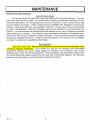
MAINTENANCE
L
PREVENTIVE MAINTENANCE
rn
Some Thinqs to Check
Your privacy blinds will retain their color and beauty with occasional cleaning. You may
order extra sets from your dealer. You should make a general maintenance inspection of your
motorhome periodically. Non-drying caulking csmpounds, available in tubes, may be used to seal
around moldings and seams. These compounds are compatible with fiberglass and aluminum
surfaces. Epoxy-resin patch kits, also available in tube form, may be used to fill any small cracks
or holes in the fiberglass. Patch and fiberglass care kits are available at most boat shops and
marinas. It is recommended that all chassis bolts be checked once a year for tightness to prevent
rattles resulting from vibration. If the exterior of your motorhome is punctured, immediately cover
the puncture with a piece of waterproof material and tape. This will prevent moisture from getting
through and damaging the interior. Keep the puncture patched in this manner until your dealer
can repair it or refer you to a qualified service facility.
Roof Inspection
Take care of your roof. Sealing around stacks and vents should be accomplished using
non-drying caulking compounds. Hot summer sun can dry out caulking, and pronounced
temperature changes can cause varying degrees of expansion and contraction with various
materials used in your roof and its components. These conditions may cause leaks, which is why
you should inspect the sealants around the vents and other components regularly. By catching a
problem in its early stages you can avoid serious repairs in the future.
C
Rev. 1-1
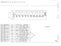
TECHNICAL SPECIFACATIONS
Specification
GLACIER 25'
Length
Exterior Width
Exterior Height
l nterior Height
Wheel Base
ECW'
GVWR~
GCWR~
25'
8' 6 "
10' 3 " (with AC)
6' 5 "
176"
11,5001b.
14,050 Ib.
20,0001b.
SUMMIT 27'
27'
8' 6 "
1 0 ' 3" (with AC)
6' 5"
176 "
13,000 Ib.
1 4 , 0 5 0 Ib.
20,0001b.
1. ECW (Estimated Curb Weight) - The weight of this motorhome as built at the factory with full fuel, engine oil, and
coolants. The UVW does not include cargo, fresh water, LP gas, occupants, or dealer installed accessories.
2. GVWR (Gross Vehicle Weight Rating) - The maximum permissible weight of the motorhome. The GVWR is equal
to or greater than the sum of the Unloaded Vehicle Weight plus the Net Carrying Capacity.
3. GCWR (Gross Combination Weight Rating) means the value specified by the motorhome manufacturer as the
maximum allowable loaded weight of this motorhome with its towed trailer or towed vehicle.
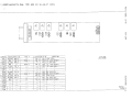
Specification
SLIDEOUT
GAS TANK
FRESH WATER TANK
WATER HEATER
GRAY WATER TANK
BLACK WATER TANK
REFRIGERATOR
FURNACE
RANGE
LIGHTING
SUMMIT 27'
GLACIER 25'
(1) 7 9 " ~ 6 6 " 4"
~1
55 GAL
40 GAL
6 GAL
40 GAL
20 GAL
6 CU FT
16,000 BTU/HR
2-BURNER COOKTOP
1211 1OV SYSTEMS
INVERTERJCONVERTER
2 0 0 0 ~ ~/ l1TO ~ A M P
TWIN BED
SOFA SLEEPER
DINElTE
72"~32"
76"~56"
72"~36"
(2) 7 9 " ~ 6 6 ~" 1 4 " . 6 6 " ~ 6 6~" 2 4
55 GAL
40 GAL
6 GAL
40 GAL
20 GAL
6 cu FT
1 9 , 0 0 0 BTU/HR
2-BURNERCOOKTOP
1211 1OV SYSTEMS
2 0 0 0/ 1
~o o~ ~ ~
tvl~
72"x3211
76"~56"
76"~36"
SPECIFICATIONS SUBJECT TO CHANGE WITHOUT NOTICE
-
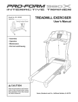
FREQUENTLY ASKED QUESTIONS
i
Problem: If at 3 campground, what kind of Amp Service is used - 15, 30 or 50?
Suggestion: Our Motor Home shore power cords are designed for 30 Amp service.
Problem: Batteries will not hold charge
Suggestion: Check the water levels. Deep Cycle Batteries need a
charge if they go dead;
a 3 Amp trickle for 2 or 3 days. A higher Amp charging rate will only give the battery a surface
charge that will not hold.
Problem: The house battery goes dead.
Suggestion: The battery may not be charging from the engine alternator. Check the fuse in the
power distribution panel (See Ford Owners Manual). Check the water levels in the batteries.
Problem: Furnace does not run overnight.
Suggestion: The batteries are low. The Furnace and Refrigerator are the two biggest draws on
the battery system.
Problem: The furnace is inoperable.
Suggestion: 1) Low batteries. 2) The furnace fan has to run at a pre-set RPM before the gas
valve will open and allow the furnace to light. 3) Check the heat vents to make sure the
"butterflies" are open. Closed vents can cause low RPM's.
Problem: The furnace blows cold air.
Suggestion: 1) Check the LP bottle to make sure that it is on. 2) Check the thermostat for the
temperature setting. 3) Check the butterflies in the heat vents to make sure that they are open all
the way.
Problem: Will not switch from generator to shore power.
Suggestion: There is a built-in transfer switch on the converter that performs this function. This
would need to be checked by a Service Center.
Problem: The Generator will not start.
Suggestion: The Generator is wired to the house batteries. The batteries may be low enough
that the Generator will not start. Start the motorhome and try starting the Generator. Check the
80 Amp Breaker located on the passenger side of the firewall (not on all models).
Problem: The Generator rattles when running.
Suggestion: 1) Check the exhaust pipe to see if it is loose. 2) The fuel line may be sucking air.
i
FREQUENTLY ASKED QUESTIONS
Problem: The propane gauge reads incorrectly.
Suggestion: Float in the tank may be stuck - take to an Authorized Propane Dealer for repair.
The tank has an 80% shut-off valve in it which is required by iaw. This means your tank, when
filled, will only read about 3/4 full.
Problem: The propane gauge is inoperable.
Suggestion: There are two gauges on the propane system. There is a sight gauge at the tank
itself, and an indicator on the Monitor Panel. If the Monitor Panel is not working, check the wire
connections at the sight gauge. Note that the gauges are in different increments - one gauge in
X'S and the other reads in 113's.
Problem: The LP Detector keeps going off.
Suggestion: This device has two functions - it will indicate a low battery as well as an LP leak.
If your LP Detector goes off, do not assume that it is a low battery condition. CHECK FOR LP
LEAKS.
Problem: No power at the outlets in Coach.
Suggestion: Check the GFCl outlet located on the shower wall just inside the back door
Problem: The TV has no reception except when on cable.
Suggestion: 1) Check the A/B switch to make sure it is on N setting. This switch is located in
the front overhead storage. This switch has 2 functions: the "A" side (which is the upper button)
controls the antenna & VCP; the "6"side (lower button) is for cable hook-up and may also be
used for a DSS antenna. 2) Check the TV menu screen for setting TV in Antenna Mode. 3)
Check the N antenna booster to make sure it is turned on.
Problem: The Roof Vent leaks air, rattles andlor will not close all the way.
Suggestion: There is an adjustment that can be made. We do have a flyer showing how to do
this; however, it is best done at a Service Center.
Problem: How do you drain the fresh water tank?
Suggestion: You can open the tank drain valve or open both line drains and turn the water pump
on and pump the water out. Be careful not to let the water pump run for an extended amount of
time without water in it.
Problem: How do you drain the black water tank?
Suggestion: Connect the drain hose to the 3" black plastic fitting. Open the 3" dump valve
manually.
Problem: The water heater is inoperable.
Suggestion: Make sure that there is water in the water heater. Check the bypass valves to
ensure they are in the proper position.
Problem: Where is the phone jack located?
Suggestion: It is located in the front overhead compartment behind the VCR.
1
FREQUENTLY ASKED QUESTIONS
Problem: What is the recommended tire pressure?
Suggestion: 70 PSI for front tires and 65 PSI in the back. You can adjust as necessary; some
suggest around 75 all around.