1
Owner's
Manual
Permanently Lubricated
Single Stage
Horizontal Portable
AIR COMPRESSOR
Model No.
919.165180
•
Safety
Guidelines
•
Assembly
•
Operation
•
Maintenance
•
Service
•
Troubleshooting
•
Repair
•
Espa_ol
CAUTION:
and
All
Operating,
and Adjustments
Parts
Read
Instructions
the
Safety
Guidelines
Carefully
Before
Sears, Roebuck and Co., Hoffman Estates, IL 60170 U.S.A.
Visit our Craftsmen
D245_0
Rsv. 0
19/11/01
website:
www.sears.€om/¢raftsman
WARRANTY
.............................................
SPECIFICATION
SAFETY
CHART
GUIDELINES
GLOSSARY
ASSEMBLY
.........
OPERATION
•
9
. ..................................
9
,
.
°
,
.
•
,
•
.
.
_
,
=
.............
.
°
,
.
.
....
,
...........................
PARTS
ESPAI_IOL
GUIDE
20
............................
21-23
.......................................
FULL
REPAIR
ONE
PARTS
YEAR
11-12
18-19
24-27
............................................
TO ORDER
.
16-17
..............................................
TROUBLESHOOTING
°
13-15
.......................................
AND ADJUSTMENTS
STORAGE
.
10
..........................................
MAINTENANCE
HOW
9
.............................................
INSTALLATION
REPAIR
3
3-8
..........................................
CYCLE
SERVICE
....................................
....................................
..............................................
ACCESSORIES
DUTY
2
28-49
.....................
WARRANTY
back cover
AIR
COMPRESSOR
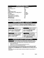
If this air compressor fails due to a defect in material or workmanship
within
one year from the date of purchase, RETURN IT TO THE NEAREST SEARS
REPAIR CENTER THROUGHOUT
THE UNITED STATES AND SEARS WILL
REPAIR IT, FREE OF CHARGE. If purchased from Orchard Supply Hardware,
return to the nearest Orchard Store and Orchard will repair it, free of charge.
If this air compressor
is used for commercial or rental purposes,
will apply for ninety days from the date of purchase•
This warranty gives you specific
which vary from state to state,
Sears,
D24580
Robebuck
legal rights
and Co., Dept.
and you may have other rights
817WA,
2-ENG
the warranty
Hoffman
Estates,
II 60179
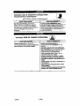
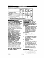
Model
No.
Max. Developed
Bore
Stroke
919-165180
HP
Voltage-Single
Phase
Minimum
Branch Circuit
Fuse Type
5.5
2.38"
1.35"
120
15 amps
Time Delay
Requirement
Air Tank Capacity
Approximate
Cut-in Pressure
Approximate
Cut-out Pressure
SCFM @ 40 psig
SCFM @ 90 psig
Refer to Glossary
25 gallons
110
135
8.4
6.2
for abbreviations,
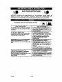
This manual contains information that is important for you to know and understand_ This information
relates to protecting YOUR S&FETY and PREVENTING EQUIPMENT PROBLEM8. To help you
recognize this information, we use the symbols below. Please read the manual and pay attention to
these sections.
Indicates an
imminently haZardous
situation which, if not avoided, will
result in _ath
or serious injury,
Indicates a potentially
_
I_l_Jllndicates
hazardous
hazardous
situation
which, if not avoided, may result in
mirror or moderate
iojury.
a potentially
situation
which, if not avoided, _
death or serious iniurv.
result in
indicates
a potentially
hazardous
situation which, if not avoided, may
result in Dt_oertv
damage.
_Some
dust cn_ted
by contains
power sanding,
sawing,
grinding,
other to
construction
activities
chemicals
known
(to the drilling,
St_e of and
California)
cause cancer, birth defects or other reproductive harm, Some example of these chemicals are:
•
lead from lead-based paints
•
crystal!Ine silica from bdcks and cement and other masonry products
•
arsenic end chromium from chemically-treated lumber
Your Hsk from these exposures vades, depending on how often you do this type of work. To reduce
your exposure to these chemicals: work in a well ventilated area, and work with approved safety
equipment, always wear MSHAJNIOeH approved, prepedy fitting face mask or respirator when using
such tools.
When using air tools, basic safety precautions should always be followed to reduce the dsk of of
personal injury.
3-ENG
D24580
SAVE THESEINSTRUCTIONS
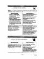
IMPROPER OPERATION OR MAINTENANCE OF THIS PRODUCT COULD RESULT IN
SERIOUS INJURY AND PROPERTY DAMAGE_ READ AND UNDERSTAND ALL
WARNINGS AND OPERATING INSTRUCTIONS BEFORE USING THIS EQUIPMENT
I: Y-'_'_F-'_I_
WARNING:
RISK OF EXPLOSION
OR FIRE
i
WHAT CAN HAPPEN
HOW TO PREVENT
IT
IT IS NORMAL FOR ELECTRICAL CONTACTS
WITHIN THE MOTOR AND PRESSURE SWITCH
TO SPARK.
ALWAYS OPERATE THE COMPRESSOR IN A
WELL VENTILATED AREA FREE OF
COMBUSTIBLE MATERIALS, GASOLINE OR
SOLVENT VAPORS.
IF ELECTRICAL SPARKS FROM
COMPRESSOR COME INTO CONTACT WITH
FLAMMABLE VAPORS, THEY MAY IGNITE.
CAUSING FIRE OR EXPLOSION.
IF SPRAYING FLAMMABLE MATERIALS,
LOCATE COMPRESSOR AT LEAST 20 FEET
AWAY FROM SPRAY AREA. AN ADDmONAL
LENGTH OF HOSE MAY BE REQUIRED.
STORE FLAMMABLE MATERIALS IN A
SECURE LOCATION AWAY FROM
COMPRESSOR.
NEVER PLACE OBJECTS AGAINST OR ON
TOP OF COMPRESSOR. OPERATE
COMPRESSOR IN AN OPEN AREA AT LEAST
12 INCHES AWAY FROM ANY WALL OR
OBSTRUCTION THAT WOULD RESTRICT THE
FLOW OF FRESH AIR TO THE VENTILATION
OPENINGS.
H_U'I RICTING ANY OF THE COMPRESSOR
VENTILATION OPENINGS WILL CAUSE
SERIOUS OVERHEATING AND COULD CAUSE
FIRE.
UNATTENDED OPERATION OF THIS
PRODUCT COULD RESULT IN PERSONAL
INJURY OR PROPERTY DAMAGE, TO
REDUCE THE RISK OF FIRE, DO NOT ALLOW
THE COMPRESSOR TO OPERATE
UNATTENDED.
024580
OPERATE COMPRESSOR IN A CLEAN, DRY.
WELL VENTfLATED AREA. DO NOT OPERATE
UNIT INDOORS OR IN ANY CONFINED AREA.
ALWAYS REMAIN IN ATTENDJU_CE WITH THE
PRODUCT WHEN IT IS OPERATING.
ALWAYS DISCONNECT ELECI_IICAL POWER
BY MOVING PRESSURE SWITCH LEVER TO
THE OFF POSITION AND DRAIN TANK DALLY
OR AFTER EACH USE.
4- ENG
WARNING:
RISK OF BURSTING
[_1
THE FOLLOWING CONDITIONS COULD LEAD TO A WEAKENING OF THE
TANK, AND RESULT IN A VIOLENT TANK EXPLOSION AND COULD CAUSE
PROPERTY DAMAGE OR SERIOUS INJURY.
WHAT CAN HAPPEN
FAILURE TO PROPERLY DRAIN
CONDENSED WATER FROM THE
TANK, CAUSING RUST AND THINNING
OF THE STEEL TANK.
HOW TO,, PREVENT
IT
i
DRAIN TANK DAILY OR AFTER EACH USE. JF
TANK DEVELOPS A LEAK, REPLACE iT
IMMEDIATELY WITH A NEW TANK OR REPLACE
THE ENTIRE COMPRESSOR.
2.
MODIFICATIONS OR ATTEMPTED
REPAIRS TO THE TANK.
3.
UNAUTHORIZED MODIFICATIONS TO
THE UNLOADER VALVE, SAFETY
VALVEj OR ANY OTHER COMPONENTS
WHICH CONTROL TANK PRESSURE,
4.
EXCESSIVE VIBRATION CAN WEAKEN
THE AIR TANK AND CAUSE RUPTURE
OR EXPLOSION.
NEVER DRILL INTO, WELD, OR MAKE ANY
MODIFICATIONS TO THE TANK OR ITs
A'I'TACHMF_J'4TS.
THE TANK IS DESIGNED TO WITHSTAND
SPECIFIC OPERATING PRESSURES. NEVER
MAKE ADJUSTMENTS OR PARTS
SUBSTITUTIONS TO ALTER THE FACTORY
SET OPERATING PRESSURES.
1.
ATTACHMENT_
&ACCESSORIES:
EXCEEDING THE PRESSURE RATING OF AIR
TOOLS, SPRAY GUNS, AIR OPERATED
ACCESSORIES, TIRES AND OTHER
INFLATABLES CAN CAUSE THEM TO
EXPLODE OR FLY APART, AND COULD
RESULT IN SERIOUS INJURY.
WARNING:
RISK FROM
FOR ESSENTIAL CONTROL OF A{R
PRESSURE,YOU MUST INSTALL A PRESSURE
REGULATOR AND PRESSURE GAUGE TO
THE AiR OUTLET (IF NOT EQUIPPED) OF
YOUR COMPRESSOR. FOLLOW THE
EQUrPMENT MANUFACTURERS
RECOMMENDATION AND NEVER EXCEED THE
MAXIMUM ALLOWABLE PRESSURE RATING OF
ATTACHMENTS. NEVER USE COMPRESSOR
TO INFLATE SMALL LOW-PRESSURE
OBJECTS SUCH AS CHILDREN'S TOYS,
FOOTBALLSj BASKETBALLS, ETC,
FLYING
OBJECTS
,J,,i
WHAT
CAN HAPPEN
HO W TO PREVENT,IT
THE COMPRESSED AIR STREAM CAN
CAUSE SOFT TISSUE DAMAGE TO EXPOSED
SKIN AND CAN PROPEL DIRT, CHIPS, LOOSE
PARTICLES AND SMALL OBJECTS AT HIGH
SPEED, RESULTING IN PROPER'W DAMAGE
OR PERSONAL INJURY,
ALWAYS WEAR ANSI Z87.1 APPROVED
SAFETY GLASSES WITH SIDE SHIELDs WHEN
USING THE COMPRESSOR.
NEVER POINT ANY NOZZLE OR SPRAYER
TOWARD ANY PART OF THE BODY OR AT
OTHER PEOPLE OR ANIMALS,
ALWAYS TURN THE COMPRESSOR OFF AND
BLEED PRESSURE FROM THE AIR HOSE AND
TANK BEFORE ATI--/=MPTINGMAINTENANCE,
ATrACHING TOOLS OR ACCESSORIES.
5-ENG
024580
WARNING:
WHAT
RISK OF ELECTRICAL
CAN HAPPEN
SHOCK
H,OW TO PREVENT
IT
NEVER OPERATE THE COMPRESSOR
OUTDOORS WHEN iT IS RAINING OR IN WET
CONDITIONS.
YOUR AIR COMPRESSOR 16 POWERED BY
ELECTRICITY. LIKE ANY OTHER
ELECTRICALLY POWERED DEVICE, IF IT IS
NOT USED PROPERLY IT MAY CAUSE
ELECTRIC SHOCK.
NEVER OPERATE COMPRESSOR WI'(H
PROTECTIVE COVERS REMOVED OR
DAMAGED.
REPAIRS ATTEMPTED BY UNQUALIFIED
PERSONNEL CAN RESULT IN SERIOUS
INJURY OR DEATH BY ELECTROCUTION.
ANY ELECTRICAL WIRING OR REPAIRS
REQUIRED ON THIS PROOUCT SHOULD BE
PERFORMED BY AUTHORIZED SERVICE
CENTER PERSONNEL IN ACCORDANCE WITH
NATIONAL AND LOCAL ELECTRICAL CODES.
ELECTRICAL GROUNDING: FAILURE TO
PROVIDE ADEOUATI_ GROUNDING TO THIS
PRODUCT COULD RESULT IN SERIOUS
INJURY OR DEATH FROM ELECTROCUTION.
SEE GROUNDING INSTRUCTIONS,
MAKE CERTAIN THAT THE ELECTRICAL
CIRCUIT TO WHICH THE COMPRESSOR IS
CONNECTED PROVIDES PROPER
ELECTRICAL GROUNDING, CORRECT
VOLTAGE AND ADEQUATE FUSE
PROTECTION.
WARNING:
WHAT
CAN
RISK TO BREATHING
HAPPEN
HOW, TO PREVENT IT,
THE COMPRESSED AIR DIRECTLY FROM
YOUR COMPRESSOR IS NOT SAFE FOR
BREATHING. THE AIR STREAM MAY
CONTAIN CARBON MONOXIDE, TOXIC
VAPORS, OR SOLID PARTICLES FROM THE
TANK. BREATHING THESE CONTAMINANTS
CAN CAUSE SERIOUS INJURY OR DEATH.
AIR OBTAINED DIRECTLY FROM THE
COMPRESSOR SHOULD NEVER BE USED TO
SUPPLY AIR FOR HUMAN CONSUMPTION. IN
ORDER TO USE AIR PRODUCED BY THIS
COMPRESSOR FOR BREATHING, SUITABLE
RLTERS AND IN-LINE SAFETY EQUIPMENT
MUST BE PROPERLY INSTALLED. IN-LINE
FILTER8 AND SAFETY EQUIPMENT USED IN
CONJUNCTION WITH THE COMPRESSOR
MUST BE CAPABLE OF TREATING AIR TO
ALL APPUCABLE LOCAL AND FEDERAL
CODES PRIOR TO HUMAN CONSUMPTION.
SPRAYED MATERIALS SUCH AS PAINT, PAINT
SOLVENTS, PAINT REMOVER, INSECTICIDES,
WEED KILLERS, MAY CONTAIN HARMFUL
VAPORS AND POISONS.
WORK IN AN AREA WITH GOOD CROSSVENTILATION• READAND FOLLOWTHE
SAFETY INGTRUCTIONS PROVIDED ON THE
LABEL OR SAFEW DATA SHEETS FOR THE
MATERIAL YOU ARE SPRAYING. USE A
NIOSWMSHA APPROVED RESPIRATOR
DESIGNED FOR USE WITH YOUR SPECIFIC
APPUCATION_
D24580
6- ENG
WARNING:
WHAT
RISK OF BURNS
HOW TO PREVENT IT
CAN HAPPEN
TOUCHING EXPOSED METAL SUCH AS THE
COMPRESSOR HEAD OR OUTLET TUBES,
CAN RESULT IN SERIOUS BURNS.
WARNING:
RISK
FROM
NEVER TOUCH ANY EXPOSED METAL
PAIRTS ON COMPRESSOR DURING OR
IMMEDIATELY AFTER OPERATION.
COMPRESSOR WILL REMAIN HOT FOR
SEVERAL MINUTES AFTER OPERATION.
DO NOT REACH AROUND PROTECTIVE
SHROUDS OR AI"rEMPT MAINTENANCE
UNTIL UNIT HAS BEEN ALLOWED TO COOL.
MOVING
PARTS
WHAT CAN HAPPEN
HOW TO pREVENT
IT
MOVING PARTS SUCH AS THE PULLEY,
FLYWHEEL AND BELT CAN CAUSE SERIOUS
INJURY IF THEY COME INTO CONTACT WiTH
YOU OR YOUR CLOTHING,
NEVER OPERATE THE COMPRESSOR WITH
GUARDS OR COVERS WHICH ARE DAMAGED
OR REMOVED.
AI"rEMPTING TO OPERATE COMPRESSOR
WITH DAMAGED OH MI,SSING PARTS OR
ATTEMPTING TO REPAIR COMPRESSOR
WITH PROTECTIVE SHROUDS REMOVED CAN
EXPOSE YOU TO MOVING PARTS AND CAN
RESULT IN SERIOUS INJURY.
ANY REPAIRS REQUIRED ON THIS PRODUCT
SHOULD BE PERFORMED BY AUTHORIZED
SERVICE CENTER PERSONNEL
WARNING:
RISK OF FALUNG
WHAT CAN HAPPEN
A PORTABLE COMPRESSOR CAN FALL
FROM A TABLE, WORKBENCH OR ROOF
CAUSING DAMAGE TO THE COMPRESSOR
AND COULD RESULT IN SERIOUS INJURY
OR DEATH TO THE OPERATOR,
I_OW TO PREVENT
IT
ALWAYS OPERATE COMPRESSOR IN A
STABLE 8ECURE POSITION TO PREVENT
ACCIDENTAL MOVEMENT OF THE UNIT.
NEVER OPERATE COMPRESBOR ON A ROOF
OR OTHER ELEVATED PosITION. USE
ADDITIONAL AIR HOSE TO REACH HIGH
LOCATIONS.
7-ENG
D24580
WARNING:
RISK
TRANSPORTING
OF PROPERTY
COMPRESSOR
DAMAGE
WHEN
(Fire, Inhalation, Damage to Vehicle Surfaces)
m,,.
i
WHAT
• iiii
CAN HAPPEN
OIL CAN LEAK OR SPILL AND COULD
RESULT IN FIRE OR BREATHING HAZARD,
SERIOUS INJURY OR DEATH CAN RESULT.
OIL LEAKS WILL DAMAGE CARPET, PAINT OR
OTHER SURFACES IN VEHICLES OR
TRAILERS.
=1 i
ii
HOW TO PREVENT
IT
ALWAYS PLACE COMPRESSOR ON A
PROTECTIVE MAT WHEN TRANSPORTING TO
PROTECT AGAINST DAMAGE TO VEHICLE
FROM LEAKS. REMOVE COMPRESSOR FROM
VEHICLE IMMEDIATELY UPON ARRIVAL AT
YOUR DESTINATION_
WARNING: RISK OF UNSAFE OPERATION
WHAT
i
CAN HAPPEN
UNSAFE OPERATION OF YOUR AIR
COMPRESSOR COULD LEAD TO SERIOUS INJURY OR DEATH TO YOU OR OTHERS-
HOW TO PREV]ENT
IT
REVIEW AND UNDERSTAND ALL
INSTRUCTIONS AND WARNINGS IN THIS
MANUAL
BECOME FAMILIAR WITH THE OPERATION
AND CONTROLS OF THE AIR COMPRESSOR.
KEEP OPERATING AREA CLEAR OF ALL
PERSONS. PETS. AND OBSTACLES.
KEEP CHILDREN AWAY FROM THE AIR
COMPRESSOR AT ALL TIMES.
DO NOT OPERATE THE PRODUCT WHEN
FATIGUED OR UNDER THE INFLUENCE OF
ALCOHOL OR DRUG6. STAY ALERT AT ALL
TIMES,
NEVER DEFEAT THE SAFETY FEATURES OF
THIS PRODUCT.
EQUIP AREA OF OPERATION WITH A FIRE
EXTINGUISHER.
DO NOT OPERATE MACHINE WITH MISSING,
BROKEN, OR UNAUTHORIZED PARTS.
D24580
8-ENG
Become familiar with these terms
before operating the unit.
CFM:
Cubic feet per minute.
SCFM:
Standard cubic feet per
minute; a unit of measure of air
delivery.
PSIG: Pounds per square inch
gauge; a unit of measure of pressure.
Code Certification:
Products that
bear one or more of the following
marks: UL, CUL, ETL, CETL, have
been evaluated by OSHA certified
independent safety laboratories and
meet the applicable Underwriters
Laboratories Standards for Safety.
Cut-In Pressure:
While the motor is
off, air tank pressure drops as you
continue to use your accessory.
When the tank pressure drops to a
certain low level the motor will restart
automatically.
The low pressure at
which the motor automatically
restarts is called "cut-in" pressure.
Cut-Out Pressure:
When an air
compressor is turned on and begins
to run, air pressure in the air tank
begins to build. It builds to a certain
high pressure before the motor
automatically
shuts off, protecting
your air tank from pressure higher
than its capacity. The high pressure
at which the motor shuts off is called
"cut-out"
pressure.
Branch Circuit: Circuit carrying
electricity from electrical panel to
outlet.
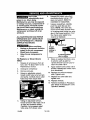
This unit is capable of powering the following Accessories.
The accessories
are
available through the current Power and Hand Tool Catalog or fuU-line Sears
stores.
Accessories
•
Oil Fog Lubricators
•
In Line Filter
•
Air Hose:l/4",
•
Tire Air Chuck
•
Quick Connector
sizes)
•
Air Pressure
various
Sets (various
Regulators
Air compressors should be operated
on not more than a 50% duty cycle.
This means an air compressor that
pumps air more than 50% of one
hour is considered misuse, because
3/8" or 1/2" I.D. in
lengths
Refer to the selection chart located
on the unit to select the tools this unit
is capable
of powering.
the air compressor is undersized for
the required air demand.
Maximum
compressor pumping time per hour is
30 minutes.
9-ENG
D24580
Contents
Air Compressor
1-
Handle
4 -
Self Tapping
2-
Wheels
2 -
Shoulder
2 -
Hex Nuts, 3/8-16
I -
Rubber
1 - 9/16"
one side of the air compressor
when installing the wheels because
the air compressor
will have a
Screw
Bolts,
tendency
3/8-16
1.
socket
1 - 1/2" socket
2.
for Assembly
or open end wrench
1.
.
3.
Handle
Install the four screws, two on
each side.
The wheels and
handle do not
provide adequate
clearance,
stability or support for pulling the
unit up and down stairs or steps.
The unit must be lifted, or pushed
up a ramp,
Strip
Clean and dry underside of air
tank leg opposite wheels.
2.
Remove the protective paper
strip from the adhesive backed
rubber foot strip.
3.
Attach the rubber foot strip to
the bottom of leg. Press firmly
into place.
securely.
Wheel
Rubber
1.
Shoulder
Bolt
Rubber Strip
D24580
Tighten securely. NOTE: The air
compressor will sit level if the
wheels are properly installed.
Assemble
Insert the handle inside the
compressor saddle and line up
the two bolt holes on each side.
Tighten
Attach wheels with shoulder
or open end wrench
Unpacking
1. Remove unit from carton and
discard all packaging. NOTE:
Save all parts bags.
Assemble
to tip.
bolts and nuts as shown.
Strip
Required
Wheels
It will be necessary
to brace or support
1 -
Tools
Assemble
of Carton
10-ENG
HOW
TO SET UP YOUR
Make sure the outlet being used
has the same configuration as
the grounded plug. DO NOT
USE AN ADAPTER.
See
illustration.
2.
UNIT
Location
of the
Air Compressor
Locate the air compressor in a clean,
dry and well ventilated area. The air
compressor should be located at
least 12" away from the wall or other
obstructions that will interfere with
the flow of air. The air compressor
pump and shroud are designed to
allow for proper cooling. The
ventilation
openings
on the
compressor are necessary to
maintain proper operating
temperature,
Do not place rags or
other containers
on or near these
openings,The
air filter must be kept
clear of obstructions
which could
reduce
Grounded
_Outlets
.
signs of damage.
4,
air flow to the air compressor.
GROUNDING
In the event of a short
circuit, grounding
reduces the risk
of shock by providing an escape
wire for the electric current, This
air compressor
must be properly
grounded.
The portable air compressor is
equipped with a cord having a
grounding wire with an appr0pdate
grounding plug (see following
illustrations). The plug must be used
with an outlet that has been installed
and grounded in accordance with all
local codes and ordinances.
1.
If these grounding
instructions
are not completely
understood,
or if in doubt as to whether the
compressor
is propedy
grounded, have the installation
checked by a qualified
electrician,
INSTRUCTIONS
RISK OF
ELECTRICAL
SHOCK.
Inspect the p,lug and cord before
each use. Do not use if there are
_
RESULT
IMPROPER
GROUNDING
CAN
IN ELECTRICAL
SHOCK.
Do not modify the plug provided. If
it does not fit the available outlet, a
correct outlet should be installed
by a qualified electrician.
Repairs to the cord set or plug
MUST be made by a qualified
electrician,
The cord set and plug with this
unit contains a grounding pin.
This plug MUST be used with a
grounded outlet.
IMPORTANT:
The outlet being used
must be installed and grounded in
accordance with all local codes and
ordinances.
11 - t=NG
D24580
Extension
Cords
Voltage
Using extension cords is not
recommended.
The use of extension
Certain air compressors can be
operated on a 15 amp circuit if the
following
conditions are met.
Instead of using extension cords
attach extra air hoses to each other
Q
1.
at the air outlet.
Jf an extension
be sure it is:
a 3-wire
cord
must be used,
extension
in good condition
no longer than 50 feet
12 gauge (AWG) or larger. (Wire
size increases as gauge number
decreases.
10 AWG and 8 AWG
DO NOT USE
Voltage supply through branch
circuit is 15 amps.
.
Circuit is not used to supply any
other electrical needs (lights,
appliances, etc.).
.
Extension cords comply
specifications.
cord that has
a 3-blade grounding
plug, and a
3-slot receptacle
that will accept
the plug on the product
may also be used.
14 OR 16 AWG.)
Protection
Refer to the specification table for the
voltage and minimum branch circuit
requirements.
cords will cause voltage to drop
resulting in power loss to the motor
and overheating.
starting
and Circuit
4.
with
Circuit is equipped with a 15
amp circuit breaker or 15 amp
time delay fuse. NOTE: If
compressor is connected to a
circuit protected
by fuses, use
only time delay fuses. Time delay
fuses should be marked "D" in
Canada and "T" in the US.
If any of the above conditions cannot
be met, or if operation of the
compressor
repeatedly causes
interruption of the power, it may be
necessary to operate it from a 20
amp circuit. It is not neoessary to
change the cord set.
D245S0
12-ENG
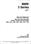
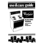
Know
Your Air Compressor
READ THIS OWNER'S
MANUAL AND SAFETY RULES BEFORE OPERATING
YOUR UNIT. Compare the illustrations with your unit to familiarize yourself with
the location of vanous controls and adjustments. Save this manual for future
reference.
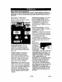
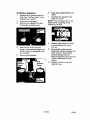
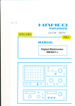
Description
Become
before
Outlet
of Operation
Gauge:
The outlet
pressure gauge indicates the air
pressure available at the outlet side
of the regulator. This pressure is
controlled by the regulator and is
familiar with these controls
operating
Pressure
the unit.
On/Auto/G.
Switch
always less than or equal to the tank
pressure.
Safety
Valve
Tank Pressure
Gauge:
The tank
pressure gauge indicates the reserve
air pressure in the tank.
Tank
Pre,_sure
Gauge
Regulator;
Controls
the air pressure
shown on the outlet pressure gauge.
Pull the knob out and turn clockwise
to increase pressure and
counterclockwise
to decrease
pressure. When the desired pressure
is reached push knob in to lock in
place.
On/Auto/Off
Switch:
Turn this
switch ON to provide automatic
power to the pressure switch and
OFF to remove power at the end of
each use.
Pressure Switch: The pressure
switch automatically
starts the
motor when the air tank pressure
drops below the factory set "cut-in"
pressure. It stops the motor when
the air tank pressure reaches the
factory set "cut-out"
pressure.
Safety
Valve: If the pressure
switch
does not shut off the air compressor
at its "cut-out" pressure setting, the
safety valve will protect against high
pressure by "popping
out" at its
factory set pressure (slightly higher
than the pressure switch "cut-out"
setting).
The drain
is located at
the base of the
air tank and is
used to drain
condensation
Drain
Valve
at the end of each use.
Cooling System (not shown):
This
compressor contains an advanced
design cooling system. At the heart
of this cooling system is an
engineered fan. It is perfectly normal
for this fan to blow air through the
vent holes in large amounts, You
know that the cooling system is
working when air is being expelled.
Air Compressor
Pump (net shown):
Compresses air into the air tank.
Working air is not available until the
compressor has raised the air tank
pressure above that required at the
air outlet.
13- ENG
D24580
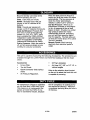
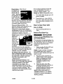
Check
Valve:
If the overload protector shuts the
motor off frequently, check for a
When the air
compressor is
operating, the
check valve is
possible voltage problem,
Low
voltage can also be suspected
when:
"open", allowing
compressed air
to enter the air
tank. When the
1.
The motor does not get up to full
power or speed.
2,
Fuses blow out when starting
the motor; lights dim and remain
dim when motor is started and is
air compressor
reaches "cut-our'
pressure, the check
valve "closes",
allowing air pressure
to remain inside the air tank.
running.
Pressure Release Valve: The
pressure release valve located on the
side of the pressure switch, is
designed to automatically release
compressed
air from the compressor
head and the outlet tube when the air
How to Use Your Unit
compressor reaches "cut-out"
pressure or is shut off. The pressure
release valve
allows the
motor to
restart freely.
When the
motor stops
running, air
will be heard
escaping
from this valve for a few seconds.
No air should be heard leaking when
the motor is running or after the unit
reaches "cut-out"
pressure.
Air Intake Filter (not shown); This
filter is designed to clean air coming
into the pump. This filter must always
be clean and ventilation openings
free from obstructions. See
"Maintenance".
Motor Overload Protector:. The
motor has an automatic reset thermal
Before First Start Up:
How to Stop:
1.
Set the On/Auto/Off
"OFF".
lever to
Serious damage
may result if the
following break-in instructions
are
not closely followed,
This procedure is required before the
air compressor is put into service and
when the check valve or a complete
compressor pump has been
replaced.
1.
Make sure the On/Auto/Off
is in the "OFF" position.
NOTE: If quick connect is installed,
pull coupler back until it clicks to
prevent air from escaping through the
quick connect.
2.
overload protector, If the motor
overheats for any reason, the
overload protector will shut off the
motor. The motor must be allowed to
cool clown before restarting. The
compressor will automatically
restart
after the motor cools.
Plug the power cord into the
correct branch cimuit receptacle.
(Refer to Voltage and Circuit
Protection
paragraph in the
Installation section of this
manual.)
3.
Open the drain valve fully
(counterclockwise) to permit air
to escape and prevent air
pressure build up in the air tank
during the break-in period.
NOTE- Always drain tank on a
washable surface or in a suitable
container to prevent damaging
staining surfaces,
D24580
lever
14- ENG
or
.
5.
6.
.
tank pressure
pressure.
2.
reaches
"cut-out"
Pull the regulator knob out and
turn clockwise to increase
NOTE: Always operate the air
compressor in well-ventilated areas
free of gasoline or other combustible
vapors. If the compressor is being
used to operate a sprayer DO NOT
Each Start-Up:
lever
lever to
pressure. When the desired
pressure is reached push knob in
to lock in place. The compressor
is ready for use.
is now ready for use.
Place On/Auto/Off
"OFF".
Turn the OnlAuto/Off
"AUTO" and allow tank pressure
to build. Motor will stop when
After 15 minutes, close the drain
valve (clockwise). The air receiver
will fill to "cut-out"
pressure and
the motor will stop.
Before
.
1.
Run the compressor for 15
minutes. Make sure the drain
valve is open and there is
minimal air pressure build-up in
tank,
The compressor
1.
How to Start:
Move the On/Auto/Off
lever to
"ON/AUTO"
position. The
compressor will start.
to
Pull regulator knob out, turn
counterclockwise
until it stops.
Push knob in to lock in place.
place near the spray area.
Attach hose and accessodes.
NOTE: The hose or accessory
will require a quick connect plug
if the air outlet is equipped with a
quick connect.
_Too
much air
pressure causes a
hazardous
risk of bursting. Check
the manufacturer's
maximum
pressure rating for air tools and
accessories.
The regulator
outlet
pressure must never exceed the
maximum pressure rating.
15- ENG
D24580
Customer
Responsibilities
Before
_ach
Jse
Check
Safety Valve
Daily or
after
Every
each
40
use
hours
Yearly
•
" Drain Tank
•
Air Filter
1(1)
Air compressor pump
and exhaust valves
1- more frequent
Every
100
hours
intake
•
in dusty
or humid
conditions
Unit cycles
automatically
when
power is on. When performing
maintenance,
you may be exposed
to voltage sources, compressed
air, or moving parts. Personal
injuries can occur. Before
performing
any maintenance
or
repair, disconnect
power source
from the compressor
and bleed off
all air pressure,
To ensure efficient operation
To Check
Safety Valve
If the safety valve
does not work
properly, over-pressurization
may
occur, causing air tank rupture or
an explosion.
1.
and
longer life of the air compressor
outfit, a routine maintenance
Before starting compressor, pull
the ring on the safety valve to
make sure that the safety valve
operates freely. If the valve is
stuck or does not operate
smoothly, it must be replaced
with the same type of valve.
To Drain Tank
schedule should be prepared and
followed, The following
routine
maintenance
schedule is geared to
1.
.
an outfit in a normal working
environment operating on a daily
basis. If necessary, the schedule
should be modified to suit the
Set the On/Auto/Off
"OFF",
,
lever to
Pull the regulator knob out and
turn clockwise to set the outlet
pressure
conditions
under which your
compressor
is used. The
to zero.
Remove the air tool or
accessory.
4.
modifications
will depend upon the
hours of operation
and the working
environment.
Compressor
outfits in
an extremely dirty and/or hostile
environment
will require a greater
frequency of all maintenance
checks.
NOTE: See "Operation"
the location of controls.
•
Pull ring pn safety valve allowing
air to bleed from the tank until
tank pressure is approximately
20 psi Release safety valve ring.
,
Drain water from air tank by
opening drain valve (counterclockwise) on bottom of tank.
section for
I__
Water will
condense in the air
tank. if not drained, water will
corrode and weaken the air tank
causing
[3_4F,_t3
1_-
I_N 1":1
a risk of air tank rupture.
.
After the water
has been drained,
close the drain valve (clockwise),
The air compressor can now be
stored.
Air Filter - Inspection and
Replacement
Risk
Compressor
heads are exposed
when filter cover is removed,
Allow compressor
servicing.
to cool prior to
!
I
2.
Remove the air filter and make
sure it is clean.
3.
If dirty, rinse air filter with warm
water and squeeze dry.
4.
Replace air filter and air filter
retainer.
NOTE; If the air filter is extremely
dirty it will need to be replaced. Refer
to the "Repair Parts" for the correct
part number.
Air Compressor
Pump
and Exhaust Valves
A dirty air filter will not allow the
compressor to operate at full
capacity. Keep the air filter clean
all times.
Remove the air filter retainer,
IMPORTANT:
Do not operate the
compressor with the air filter
removed.
NOTE: If drain valve is plugged,
release all air pressure. The valve
can then be removed, cleaned, the
reinstalled.
Hotbum.
surfaces.
of
Air
1.
at
Intake
Once a year have a Trained Service
Technician check the air compressor
pump intake and exhaust valves.
Filter
Retainer
I
17- ENG
D24580
Unscrew the check valve (turn
counterclockwise)
using a 7/8"
open end wrench. Note the
orientation for reassembly.
.
Unit cycles
automatically
when
power is on. When doing
Maintenance,
you may be exposed
to voltage sources, compressed
air
or moving parts. Personal injuries
can occur. Before performing
any
Maintenance
or repair, unplug the
compressor
and bleed off all air
pressure.
Using a screwdriver, carefully
push the valve disc up and
down. NOTE: The valve disc
,
should move freely up and down
on a spring which holds the valve
disc in the closed position; if not
the check valve needs to be
ALL MAINTENANCE
AND REPAIR
OPERATIONS
NOT LISTED MUST
BE PERFORMED
BY A TRAINED
SERVICE TECHNICIAN.
Before
•
cleaned or replaced.
servicing:
open
position
nothing is
visible.
Unplug or dlsconnect
electrica
supply to the air compressor.
Bleed tank of pressure.
Allow the air compressor
to
cool.
o
•
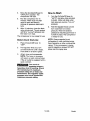
To Replace
Valve
1.
.
3.
4.
or Clean
In closed position
disc is visible.
Check
Release all air pressure from air
tank. See "To Drain Tank" in the
Maintenance
section.
8.
Clean or replace the check valve.
A solvent, such as paint or
varnish remover can be used to
clean the check valve.
9.
Apply sealant to the check valve
threads. Reinstall the check valve
Unplug air compressor.
Remove shrouds.
(turn clockwise).
10.
Using an adjustable wrench,
loosen outlet tube nut at air tank
Replace the pressure
tube. Tighten nuts.
release
1 1. Replace the outlet tube and
tighten nuts.
and pump. Carefully move outlet
tube away from check valve.
12. Replace shrouds.
13. Perform the Break-in Procedure.
See "Break-in Procedure"
in the
Operation
5.
Using an adjustable wrench,
loosen pressure relief tube nut at
air tank and pressure switch.
Carefully move pressure relief
tube away from check valve.
D_4SS0
18-ENG
section,
6.
To Replace Regulator
1.
2.
3.
Apply pipe sealant tape to the
nipple.
Assemble the regulator and
orient as shown_
Release all air pressure from air
tank. See '=To Drain Tank" in the
Maintenance section.
7.
Unplug air compressor,
Remove the regulator ring and
remove the console cover.
NOTE: Arrow indicates flow of air.
Make sure it Is pointing in the
direction of air flow,
Reg
.
4.
5.
Remove the outlet pressure
gauge, tank pressure gauge, and
quick connect (if equipped) from
the regulator.
Remove
9.
Reassemble
outlet pressure
gauge,tank
pressure gauge, and
quick connect. Orient outlet
pressure gauge and tank
pressure gauge to read correctly.
-Rghten quick connect with
wrench.
10,
Replace console
regulator ring.
the regulator.
Pressure
Gauge
lg-
Reapply pipe sealant to outlet
pressure gauge and quick
connect.
ENG
cover
and
O24580
Before you store the air compressor,
make sure you do the following:
1.
Water will
condense
in the air
tank. If not drained,
corrode and weaken
Review the "Maintenance"
section on the preceding pages
and pen_orm scheduled
maintenance
as necessary.
2,
3.
Set the On/Auto/Off
"OFF".
Turn the regulator
counterclockwise
outlet pressure
4.
Remove
causing
7.
NOTE; If drain valve is plugged,
release all air pressure,
The valve
can then be removed, cleaned, then
reinstalled.
and set the
to zero.
the air tool or
.
Store the air compressor
and dry location.
Drain water from air tank by
opening drain valve on bottom of
tank.
D24580
Protect the electrical cord and air
hose from damage (such as
being stepped on or run over).
Wind them loosely around the
compressor handle.
Pull ring on safety valve allowing
air to bleed from the tank until
tank pressure is approximately
20 psi. Release safety valve ring.
6.
a risk of air tank rupture.
After the water has been drained,
close the drain or drain valve.
lever to
accessory.
5.
water will
the air tank
20- ENG
in a clean
compressed
any repairs,
pressure.
Performing
repairs may expose voltage sources, moving
parts or compressed
air sources, moving parts or
air sources. Personal injury may occur. Prior to attempting
unplug the air compressor
and bleed off all air tank air
PROBLEM
Excessive
tank
pressure - safety
valve pops off.
CAUSE
CORRECTION
Pressure switch does
shut off motor when
compressor reaches
out" pressure.
not
"cut-
Pressure switch "cut-out"
too high.
Air leaks at
fittings.
Tube fittings are not tight
enough.
Move On/Auto/Off
lever to
the "OFF" position,
if the
outfit does not shut off
contact a Trained Service
Technician.
Contact a Trained Service
Technician.
Tighten fittings where air can
be heard escaping. Check
fittings with soapy water
solution. Do Not
Overti_lhten.
Air leaks at or
inside check
valve
Check
valve seat damaged.
A defective check valve
results in a constant air leak
at the pressure release valve
when there is pressure in the
tank and the compressor is
shut off. Replace check
valve. Refer to the "To
Replace or Clean Check
Valve" in the "Service and
Adjustment"
Air leaks at
pressure switch
release valve.
Air leaks in air
tank or at air
tank welds.
section_
Defective pressure switch
release valve.
Contact a Trained Service
Technician.
Defective
Air tank must be replaced.
Do not repair the leak_
air tank.
Do not drill into, weld or
otherwise
modify air tank
or it will weaken. The tank
can rupture
Air leaks
between head
or explode.
Contact a Trained Service
Technician.
Leaking seal.
and valve plate.
21-ENG
D24580
PROBLEM
Pressure reading
on the regulated
CAUSE
CORRECTION
It is normal for "some"
If there is an excessive
_ressure drop to occur.
amount of pressure drop
when the accessory is used,
pressure gauge
drops when an
accessory
used.
adjust the regulator following
the instructions in the
is
"Description
of Operation"
paragraph in the "Operation
Section.
NOTE: Adjust the regulated
_ressure under flow
conditions
(while accessory
is bein_l used).
Knocking
Noise.
Possible
valve.
defect
in safety
..
Operate safety valve
manually by pulling on ring.
If valve still leaks, it should
be replaced.
Compressor
is
not supplying
enough air to
operate
accessories.
Defective
check valve.
Prolonged
air.
excessive
Remove and clean, or
replace.
use of
Decrease
amount of air
Usage.
Compressor
is not large
enough for air requirement.
Check the accessory
air
requirement.
If it is higher
than the SCFM or pressure
supplied by your air
compressor, you need a
larger compressor.
Hole in hose.
Check and replace if
required.
Check valve restricted.
i Remove
and clean, or
replace.
Air leaks,
Restricted
Tighten
air intake filter
fittings.
Clean or replace air intake
filter. Do not operate the air
compressor with the filter
removed. Refer to the "Air
Filter" paragraph in the
"Maintenance"
section.
Regulator knob
has continuous
air leak.
D24580
Damaged
regulator
22- ENG
Replace
CAUSE
PROBLEM
CORRECTION
Replace
Damaged regulator
Regulator witl
not shut off air
outlet.
=ill
J
Motor
run_
will not
Motor overload protection
switch has tdpped
Let motor cool off and
overload switch will
automatically reset.
Tank pressure exceeds
_ressure switch "cut-in"
Motor will start automatically
when tank pressure drops
below "out-in" pressure of
_ressure switch.
_ressure:
Extension cord is wrong
length or gauge.
Check for proper gauge wire
and cord length_
Check
Remove
valve stuck
open.
and clean, or
replace.
Loose electrical
Possible
defective
connections
motor or
starting capacitor.
Paint spray on internal
motor
}arts.
Pressure
Jressure
release valve on
switch has not
unloaded
head pressure.
Fuse blown,
circuit breaker
tripped.
Check wiring connection
inside pressure switch and
terminal box area.
Have checked by a Trained
Service Technician.
Have checked by a Trained
Service Technician.
Do not
operate the compressor in
the paint spray area. See
flammable vapor warning.
Bleed the line by pushing the
lever on the pressure switch
to the "off" position; if the
valve does not open, replace
switch.
1. Check fuse box for blown
fuse and replace as
necessary_ Reset circuit
breaker, Do not use a fuse
or circuit breaker with
higher rating than that
specified for your particular
branch circuit.
2. Check for proper fuse. You
should use a time delay
fuse.
3. Check for low voltage
conditions and/or proper
extension cord.
4. Disconnect the other
electrical appliances from
circuit or operate the
compressor on its own
branch circuit.
23- ENG
D24580
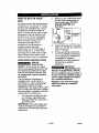
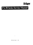
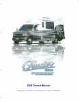
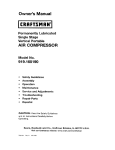
Air Compressor
Model
Number
919.165180
46
D24580
24-ENG
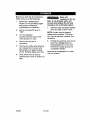
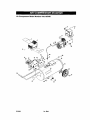
Air Compressor
Model
Number
919.165180
KEY
NO.
1
2
3
4
5
6
7
+ 8
+ 9
10
11
12
13
14
15
16
17
19
22
23
24
26
27
PART NO.
CAC-1317
AC-0029
LA_3367
D24584
LA-3162
ACG-408
SSF-981
CAC-1373
CAC-1372
AC-0012
CAC-61
Z-AC-0009-1
Z-AC-0010-1
AC-0027-2
SSP-480
LA-3021
AC-0631
AC-0007
97503734
H-2101
7-AC-0758
SSP-7811
AC-0028
DESCRIPTION
Front Shroud
Rear Shroud
31
32
33
34
37
38
39
40
41
SSP-782141
SSG-3105
SSP-7813
AC-0097
SUDL-413-2
ACG-18
91895680
ACG-19
Z-D22655
Compression Nut (Torque 100-120
O-Ring
Nut Sleeve Assembly 3/8"
Outlet Tube
42
43
44
45
46
47
48
49
50
LA-3069
LJk-3027
SSP-470-1
SS-2707
SUDL-6-I
CAC-60
D23138
SSF-8080-ZN
AC-0564
Label, Performance
Label, Billboard
Label, Maintenance
Fastener Assembly (3 used-Torque 15-25 in.-Ibs.)
Screw Hex Head Self Tapping (4 used)
Filter Retainer
Foam Filter
Console
Ring, Panel Mounting
Gauge, Right Hand
Gauge, Left Hand
Manifold
Nipple, 1/4 x 2.5"
Label, Warning
Check Valve
Regulator
Safety Valve
Adapter
Pressure Switch
Nut Sleeve Assembly
Pressure Relief Tube
1/4" (2 used)
in.-Ibs.)
Cord Assembly
Cap, Saddle Mount (2 used)
Screw, 1/4-20 x .75" (2 used- Torque 9-12 ft.-Ibs.)
isolator (3 used)
Tank, 25 Gallon
Label, Craftsman
Label, Drain Tank
Hex Reducer Bushing
Drain Valve
Strip, Rubber Foot
Shoulder Bolt (2 used)
Wheel (2 used)
Hex Nut 3/8" (2 used)
Handle
25- ENG
D245B0
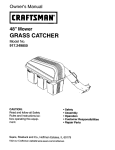
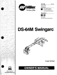
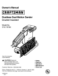
Air Compressor
Model
Number
919o165180
68
66
_-------
6S
(_'_
53
63
_
56--------_
D24580
26-ENG
57
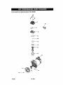
Air Compressor
Model
Number
919.165180
KEY
NO.
52
53
PART NUMBER
Z-D23360
Z-AC-0140
DESCRIPTION
Motor
54
AC-0108
Eccentric
Fan
Beadng
56
SSF-586
Screw
1/4-20
UNC
x ,75"
57
>x58
SSF-615
Screw
1/4-20
UNC
x 1,25"
Cylinder
Sleeve
Connecting
Rod Assembly
> 59
>x60
DAC-308
Formed
> 61
ACG-29
>x62
>x63
SSF-3158-1
SSG-8156
Connecting
Rod Cap
Screw 10 - 24 x .75", T25
64
Z-AC-0032
>x65
ACG-45
66
CAC-1371
67
68
AC-0037
SSF-927
Not Illustrated
D24580
x
>
K-0650
KK-4835
+
KK-5041
Compression
Ring
(2 used)
O-Ring
Valve Plate Assembly
O-Ring
Muffler
Head
Screw
1/4-20
x 1,125"
THD (4 used)
Owners Manual
Compression Ring Kit
Connecting Rod Kit
Muffler/Foam Kit
27-ENG
D24580