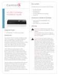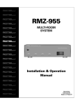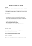
1
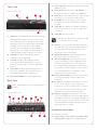
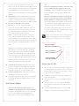
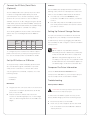
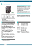
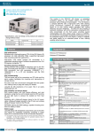
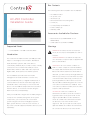
™
Box Contents
The following items are included in the HC-250 box:
• HC-250 Controller
HC-250 Controller
Installation Guide
• AC power cord
• IR emitters (4)
• Universal Television Mounting Plate
• Screws (4)
• Contact/Relay Terminal Block
• Ferrite clamps (4)
• Warranty Card
Accessories Available for Purchase
• Rack Mount Kit (C4-1URMK1B-B or C41URMK2B-B)
• Serial Cable Kit (C4-CBL3.5-DB9B)
Supported Model
• C4-HC250-BL – HC-250 Controller, Black
Introduction
Warnings
WARNING! To reduce the risk of electrical
shock, do not expose this apparatus to rain or
moisture.
AVERTISSEMENT! Pour réduire le risque de
The Control4® HC-250 Controller (HC-250) provides
choc électrique, n’exposez pas cet appareil à la
ways to control lights, home theaters, distributed
pluie ou à l’humidité.
audio and video systems, and other devices
controlled by Infrared (IR), IP, Serial, Contact, or Relay
CAUTION: In an over-current condition on
connections. The Controller has a fast processor,
USB or contact output the software disables
built-in WiFi, HDMI for audio and video, improved
the output and then blinks the power LED for
ZigBee radio, and is perfect for smaller systems!
10 seconds. When a USB overcurrent fault is
detected, you will see the power light blink the
The HC-250 also provides extensive media
LED five (5) times per second. When a contact
management for audio and video content: CDs,
overcurrent fault is detected, you will see the
DVDs, and Blu-ray Discs, or digital media stored on
power light blink the LED 12 times a second.
connected devices. Use an external storage device
After the 10-second blinking period is over the
with USB or NAS connectivity to store music and
over-current circuit will be re-enabled. If the
photos. The HC-250 fits easily behind a TV, stacked
over-current condition remains, then the same
with AV devices, or mounted on a rack using the
sequence will repeat itself.
Rack Mount Kit (sold separately).
ATTENTION : Dans une condition de
surintensité sur USB ou sortie de contact le
After you install and configure the HC-250 (using the
logiciel désactive sortie, puis le DEL Power
Composer Pro software) along with other system
clignote pendant 10 secondes. Quand une
components, your customers can control their
erreur de condition de surintensité sur USB
system using the On-Screen Navigator, MyHome
est détectée, vous verrez le DEL Power
apps, System Remote Controls, Touch Screens, or
clignoté le DEL (5) fois par seconde et puis
any other Control4-supported interface devices (sold
quand un défaut de condition de surintensité
separately).
sur contact est détecté, vous verrez le DEL
1
™
The software required to configure this device is
Composer Pro. See the Composer Pro User Guide for
details.
HC-250 Specifications
HC-250 Controller
Installation Guide
Model Number
C4-HC250-BL
Network
Ethernet—required
WiFi (only supported
when the unit is used in a
single-Controller system or as a
Secondary Controller)
Media Recognition
Online CD/DVD/Blu-ray
recognition and media information
service. Supports MP3, AAC, FLAC.
Video
HDMI 1.4 output; Component
Video output; SD 480I; HD 720p,
50-60Hz.
Audio Playback Formats
MP3: 32kbps to 320kbps, CBR,
VBR, AAC, and FLAC
Display
LED indicators
Power Requirements
100-240 VAC, 60/50 Hz, 0.25 A
PoE requirement: 13W
Power Consumption
Max: 44W, 150 BTUs/hour.
Idle: 24W, 82 BTUs/hour
Operating Temperature
32˚ - 104˚ F (0˚ - 40˚ C)
Storage Temperature
-4˚ - 149˚ F (-20˚ - 65˚ C)
IR Out
5V 27 mA max/output
IR Capture
0-60 KHz
Contact (1)
DC - 36V maximum operation (low
voltage)
Maximum output current for 12V
rail: 125mA
Relay (1)
AC - 36V, 2A
DC - 24V, 2A
maximum operation (low voltage)
Dimensions (H x W x D)
1.23” (31.19 mm) x 8.59” (218.13 mm)
x 4.92” (125.01 mm)
have a two-prong AC power cord. You can find
Weight
1.3 lbs/0.589 kg
additional PoE information on the Control4
Shipping Weight
2.7 lbs/1.224 kg
clignoté 12 fois par seconde. Après la période
de 10 secondes de clignotement, le circuit de
sur-courant sera réactivé. Si la condition de
surintensité reste donc la même, la séquence
se répète.
For more information, refer to the Products or
Documentation pages at www.control4.com.
Requirements and Specifications
NOTES:
(1) We recommend using Ethernet rather than
WiFi for the best network connectivity.
(2) The Ethernet or WiFi network should
be installed prior to starting the HC-250
installation.
(3) The HC-250 is only compatible with PoE
injectors that have DC ground isolated from
AC ground. The easiest way to determine if
this is the case is to use PoE injectors that only
Knowledgebase.
(4) Ferrite clamp installation. When installing
Additional Resources
a Control4® HC-250 Controller, also install the
enclosed ferrite clamps as described in this
The following resources are available for more
document.
support.
Ethernet cable. Install two (2) ferrite clamps
on the Ethernet cable no farther than 6 inches
• Control4 Knowledgebase and Forums
from the HC-250 Ethernet jack.
• Control4 Technical Support
Video cable. Install two (2) ferrite clamps on
• Control4 website: http://www.control4.com
each end of the HDMI or Component video
• Composer documentation in online help or PDF
cable no farther than 6 inches from the HC250 and the TV.
2
format available on the Dealer portal
Front View
1
Power Plug Port. AC power receptacle for an IEC
Figure 1. Front View
2
Ethernet/PoE. RJ-45 jack for a 10/100 BaseT
320 power cord.
Ethernet connection. Supports PoE (802.3af).
5
2
1
3
3
Audio In (1). 3.5 mm jack for stereo channel input
(line level) for one (1) stereo analog source.
4
Audio Out (1). 3.5 mm jack for stereo channel
line output (line level) for amplifiers or audio
switches.
5
Video Out. An HDMI port to display navigation
menus on a monitor or TV. Also an Audio Out
over HDMI.
4
1
6
WiFi LED. This LED blinks first Red, then Orange,
NOTE: Use only an HDMI or Component cable
and finally Blue during the boot process. When
in one of these ports, not both.
the operating system is running, the WiFi driver
changes the LED color depending on the signal
7
strength of its connection to its associated
See “Using External Storage Devices” in this
Orange=Fair to Good, Blue=Excellent, Red=Poor
Signal Strength, and No Light=No connection.
document for more information.
8
Data LED. The Blue LED indicates that the
9
Link LED. The Blue LED indicates that the
emitters and serial devices. Ports 1 and 2 can
Composer project and is communicating with
be configured independently for serial control,
Director.
e.g., receivers or disc changers, or for IR control.
Power LED. The Blue LED indicates that AC or
See “Set Up IR Emitters or IR Blaster” in this
PoE power is present. The Controller turns on
document for more information.
immediately after power is applied to it.
5
10 Factory Restore Button. Restores the Controller
IR Window/IR Blaster. For learning IR codes.
to its factory defaults. This also reboots the
Controller.
Back View
11 Contact (1). Pluggable terminal block connector
for one (1) dry contact closure, logic input
NOTE: Audio cables are not provided with this
connection, e.g., door contact sensor, or motion
product.
sensor. Provides power for small devices (12V),
signal input (SIG), and return path (GND).
Figure 2. Back View
1
2
IR and Serial Outs (4). 3.5 mm jacks for up to
four (4) IR emiiters or for a combination of IR
Controller has been identified in a Control4
4
Identification Button. Easily-pressed button to
identify the device in Composer Pro.
Controller is streaming audio.
3
USB. One (1) port for an external storage device
or a USB drive (e.g., FAT32-formatted devices).
access point. Color/signal strength indicators:
2
Video Out. Component port.
3
12 Relay (1). Pluggable terminal block connector
4
5
6
7
for one (1) Normally Closed or Normally Opened
9
8
switchable connection, e.g., a blind, a fireplace, or
a projector screen. The set contains a connection
for Normally Opened (NO), Normally Closed
(NC), and Common (COM).
Installation Instructions
10
11
12
To install the Controller:
1
Ensure that the home network is in place before
starting system setup. The HC-250 requires a
3
wall.
network connection (Ethernet - preferred or
WiFi) to use all of the features as designed. When
• Mount the HC-250 horizontally or vertically using
connected, the Controller can access web-based
one (1) standard double-gang back box (sold
media databases, communicate with other IP
separately). Install a standard double-gang back
devices in the home, and access Control4 system
box allowing the screws to protrude .08” from
the wall.
updates.
2
Mount options. The HC-250 can be mounted or
• Mount the HC-250 horizontally or vertically (see
placed behind a TV, mounted on a wall, placed
Figure 3) using four (4) screws (not provided)
in a rack, or stacked on a shelf. See “Wall Mount
placed directly into a wall stud or studs. Using
Options” below if mounting the HC-250 on a wall.
the mounting plate as a template, screw the four
Connect the HC-250 to the network.
(4) screws into a stud to align with the four (4)
• Ethernet. To connect using an Ethernet
center slots for vertical positioning or into two
3
connection, plug the data cable from the home
(2) studs to align with the four (4) corner slots
network connection into the Controller’s RJ-45
for horizontal positioning and allowing the screws
port (labeled “Ethernet”) and the network port
to protrude .08” from the wall.
on the wall or at the network switch.
• WiFi. To connect using WiFi, first connect the
NOTE: To check the fit of the screws, place the
unit to Ethernet, and then use Composer Pro’s
wall mounting plate over the screws before
System Manager to reconfigure the unit for WiFi.
attaching it to the bottom of the Controller.
You can find sample instructions in the Composer
Pro User Guide, “Configuring Speaker Point for
Figure 3. Screw Location
WiFi.”
Slots for mounting
Controller horizontally
WiFi LED. The LED blinks Orange and then Blue
during the boot process. When the operating
Holes for attaching
plate to Controller
system starts running, the WiFi driver changes
the LED color depending on the signal strength
of its connection to its associated access point.
Colors for signal strength: Orange=Fair to Good,
Slots for mounting
Controller vertically
Blue=Excellent, No Light=No connection or not
enabled, and Red=Poor signal strength.
4
Power up the Controller. Plug the power cord
into the Controller’s power plug port and then
into an electrical outlet. If you are powering the
Mount the HC-250
1
mounting plate to the bottom of the Controller.
Controller using PoE, you can skip this step.
5
6
Set up any external storage devices as described
in “Setting Up External Storage Devices” in this
document.
Wall Mount Options
• Mount the HC-250 horizontally using one (1)
standard single-gang back box (sold separately).
The wall mounting plate has four (4) horizontal
sets of slots. Install a single-gang back box
allowing the screws to protrude .08” from the
4
Ensure that the narrow end of the slots is on top
Connect system devices. Attach the devices as
described in “Connect the Devices.”
Use the four (4) screws (provided) to attach the
when the device is installed.
2
Arrange the wires to fit in the wire channels on
the mounting plate.
3
Line up the slots on the mounting plate with the
screws.
4
Press the device onto the screws and slide it
down until the screws are in the narrow end of
the slots.
5
Connect all applicable devices to the HC-250
using the connection options described next.
Connect the IR Ports/Serial Ports
(Optional)
IR Blaster
The HC-250 provides four (4) IR ports; Ports 1 and
learning codes, which is located just left of the front
2 can be reconfigured independently for serial
communication. If not used for serial, they can be
The HC-250 is also equipped with an IR blaster, for
LEDs. To use the blaster rather than an IR emitter:
1
Controller to the IR In for the device you want to
used for IR. Connect a device to the HC-250, for
example, a receiver or disc changer, using the special
serial cable (optional, C4-CBL3.5-DB9B). Serial ports
control.
2
Test and verify that the HC-250 is positioned in
such a way that the blaster can reach the device
support many different baud rates (acceptable range:
you want to control.
1200 to 115200 baud for odd and even parity).
The following table shows the serial communication
In Composer, connect the IR Blaster of the
Setting Up External Storage Devices
values. Also see Knowledgebase article #268 for
You can store and access media from an external
pinouts.
storage device, for example, a network hard drive
Hardware
Flow
Control
Odd
Parity
Even
Parity
No
Parity
Serial Port 1
X
X
X
Serial Port 2
X
X
X
Other
or USB memory device, by plugging the USB drive
into the USB port and configure or scan the media in
Composer Pro.
NOTES:
(1) We support only USB drives that are
To configure a port for serial or IR, make the appro-
externally powered or USB sticks (solid state).
priate connections in your project using Composer
Self-powered USB drives are not supported.
Pro. See the Composer Pro User Guide for details.
(2) When using USB storage devices on an
HC-250, you can only use one (1) partition with
Set Up IR Emitters or IR Blaster
a 2TB maximum size. This limitation applies to
the USB storage on all other Controllers also.
Your system may contain third-party products that
are controlled through IR commands. To provide
a way for the Controller to control a device that
only recognizes IR commands, complete one of the
following setups:
• IR Emitters
• IR Blaster
IR Emitters
1
Composer Pro Driver Information
Select the Home Controller HC250 driver in
Composer Pro and add it to your Composer project.
See the Composer Pro User Guide for details.
Troubleshooting
Factory Restore Button
Plug the 3.5 mm connector end of one of the four
CAUTION! The Factory Restore process will
(4) IR stick-on emitters provided into an IR Out
remove the Composer project.
port on the HC-250.
2
Place the stick-on emitter end over the IR
receiver on the Blu-ray player, TV, or other target
device to drive IR signals from the HC-250 to the
target.
To restore the HC-250 for system recovery to the
factory default image, perform the following steps:
1
Disconnect power to the HC-250.
2
Insert one (1) end of a paper clip into the small
hole on the back of the HC-250 that is labeled
‘Factory Restore.’
5
3
While pressing and holding the Factory Restore
button, power on the HC-250.
4
Hold the button until the WiFi Status LED blinks
Orange. This should take five (5) to seven (7)
seconds. The Status LED will blink Orange while
the restore is running.
Factory Resets
• Press the Factory Restore button, but do not hold
it down. The Controller will reset.
Identification Button (Network Reset)
To reset the HC-250 network settings to the default,
perform the following steps:
1
Disconnect power to the HC-250.
2
While pressing and holding the ID button on the
back of the HC-250, power on the HC-250.
3
Hold the ID button until the Data, Link and Power
LEDs are solid Blue, then immediately release the
button.
4
If during the boot sequence the Status LED stays
Orange, press and hold the Identification button
until the LED blinks Blue, and then release it.
Regulatory/Safety Information
To review regulatory information for your particular
Control4 products, see the information located on
the Control4 website at: http://www.control4.com/
regulatory/.
Warranty
Go to http://www.control4.com/warranty for details.
About This Document
Part number: 200-00240, Rev. D 08/17/2012
control4.com |
6
™
©2012 Control4. All rights reserved. Control4, the Control4 logo, the Control4 iQ logo and the Control4 certified logo are registered trademarks or trademarks of Control4 Corporation in
the United States and/or other countries. All other names and brands may be claimed as the property of their respective owners.