1
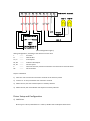
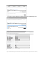
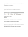
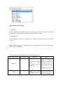
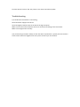
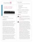
Wireless Puck Switch User Manual
Overview
This is a Non-Proxy driver that implements no Control4 Proxy. We need to add
“inSona_NonDimmable_Light” driver and then make connections between them. With the use of
the additional light driver, puck switch supports all of the Light (V2) proxy commands and events.
Product Features
1) Seamlessly dock Control4 Home Controllers, such as HC200, HC300, HC250, HC800,etc;
2) Work as a Zigbee router so that other device can join the mesh via the puck switch;
3) Provide two contact inputs, two indicator LED outputs, as well as two line voltage outputs;
4) Work with 12V keypad and achieve light control in Control4 system;
5) OTA support to update firmware through Zigbee;
6) Support all of Control4 Light V2 commands and events;
7) Standard or high Radio power level is selectable by modifying driver property;
Installation Guide
1) Installation position of Equipment must meet the following requirements
Within the range of Zigbee communicating network
Avoid 2.4G communication channel conflict with Wi-Fi, Bluetooth.
Keep away from metal objects
Important: Strictly follow the requirements above so that the product can work efficiently!
K2
K1
C
D2
D1
NC
L2
L1
L
N
Puck Switch Terminal
Lamp 1 Lamp 2
Live
External Switch
+12V
------ Common
Netural
LOAD 1
LOAD 2
LED 2
LED 1
Button/Switch 2
Button/Switch 1
(Wire Configuration Figure)
Wiring Configuration, according to the silkscreen on the shell
L
------Line Wire
N
------Neutral Wire
L1, L2
------Load outputs
D1, D2 ------Indicator LED outputs
K1, K2 ------Contact inputs
C
------Common terminal, must be connected to 12V terminal on external switch
NC
------Not connected
Steps to installation
1) Short the ‘12V’ terminal and ‘common’ terminal on the auxiliary switch
2) Connect ‘C’ on the puck switch with ‘Common’ terminal
3) Match the ‘K1’,’K2’ with switch outputs on auxiliary switches
4) Match the ‘D1’,’D2’ with indicator LED inputs on auxiliary switches
Driver Setup and Configuration
1) Add Driver
Device type is ‘others’, Manufacture is ‘inSona’, double click to add puck switch driver
Device type is ‘Light V2”, Manufacture is ‘inSona’, double click to add additional light driver
2) Driver Properties
Light 1 Status/Light 2 Status: Show current status of light;
Light 1 Default Status/Light 2 Default Status: Set the default status of light when device reboots;
Button 1 Attach/Button 2 Attach: Set to “AUTO ATTACH” to achieve keypad function, otherwise
Light control;
Debug Mode: Control the output log of driver;
Radio Power Level: Set the Zigbee Radio Power level to enhance link quality;
Firmware Update: Display the current firmware version and OTA update information;
Properties mentioned above are the main setting options which user must know;
3) Connections
Make connections between the two drivers, now user can control puck switch
through Control4 Light V2 Proxy;
4) Actions
Update Firmware: - button used to update the firmware. If "Firmware Update" in the
Properties tab reads "xxxx is available", users shall press this button to update firmware;
Force Update Firmware: - button used to force a firmware update included in this driver. User
can also use this button to force downgrade the firmware to an older one;
Set Radio Power:
- Button used to modify the current Zigbee radio power level of this device;
Get Radio Power: - Button used to show the current Zigbee radio power level of this device in
the lua tab when Debug Mode is true;
Notice: Standard power level is used in most cases, be careful when you change it.
5) Events
When ‘Button xx Attach’ property is set to ‘Attach Nothing’, puck switch can be used as a keypad
device, we have the same button events as Control4 device;
Operation and Display
1) Identify
Press the ID button (Identify Button) 4 times for identifying, the Green LED starts to blink. When
the device successfully joined the network, Green LED will be turned off.
2) Leave Mesh
Press the ID button 9 times to leave Zigbee mesh. When the device goes offline, the Red LED
turns on.
Note: button beside the “inSona” logo on the puck switch and the first auxiliary
switch work as ID Button;
This table describes the ID Button functions and LED status
Button Tap Function
Button Sequence
LED status
Remarks
Power On
Red LED and Green LED
binks
once
successively, and red
LED turns on
When the relay has
joined the network and
powered on again, the
green LED will turn on a
while and turn off,
indicating rejoin process
Identify
Green
LED
starts
blinking then goes off.
If Green LED doesn’t
blink, you shall press the
button 4 times again
4
Leave Zigbee Mesh
9
Red LED turns on
1. If Red LED remains
off, then the operation
has failed. Please press
the button 9 times
again.
2. Uers can’t control the
device until rejoining the
Zigbee Mesh
OTA Update
Device support OTA (Over The Air), that means you can update firmware through Zigbee.
The “Firmware Update” in Properties Tab will indicate the latest firmware version when new
updates are available.
If you want to update the firmware, switch to Action tab
Click Update Firmware button to start updating. The “Firmware Update” in Properties Tab will
display the update progress. The new firmware will be downloaded in proximately 10 minutes.
File verification will be performed after downloading.
IMPORTANT!: The device will restart automatically and load the new firmware after
verfication. Do not cut off the power during the process as it may lead to non-repairable damage.
Usually the loading process will finish in 1 minutes.
After the loading process, Firmware Update will display “Firmware is updated”, showing the
operating firmware has been updated to the version of the driver.
If the update fails or you need to redo update or downgrade, use the Force Update
Firmware button in Action Tab. The process is the same to Firmware Update.
Troubleshooting
1) if the Wireless Puck Switch is not working,
Check the Power Supply of the device
Check the Zigbee network status of the device through Composer.
Make sure the Connections between drivers are connected according to the instructions.
Make sure the light works normally.
2) If you find the green LED is always on after the device is powered on, please press the button 9
times to leave the former Zigbee mesh. Then press 4 times to join the network.