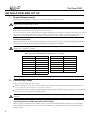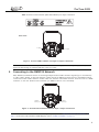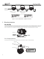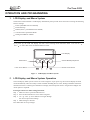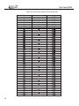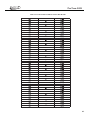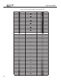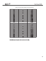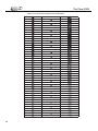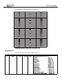
1
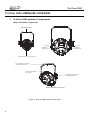
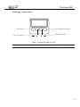
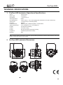
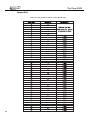
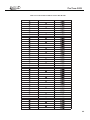
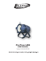
ProTron LED
USER MANUAL
Version 2.0 24-004-3533-00
ProTron LED
TABLE OF CONTENTS
TABLE OF CONTENTS
PREFACE
About this Manual ........................................................................................................................................ 3
Included Items .............................................................................................................................................. 3
Accessories ................................................................................................................................................. 3
ProTron LED Luminaire Power Input Cables (North American Models Only) .................................................. 3
ProTron LED Luminaire Accessories ........................................................................................................ 3
ProTron LED LUMINAIRE OVERVIEW
ProTron LED Luminaire Components .............................................................................................................. 4
Major Luminaire Components .................................................................................................................. 4
LCD Display / Menu System ................................................................................................................... 5
INSTALLATION AND SET UP
Power Requirements ...................................................................................................................................... 6
AC Power Operation ............................................................................................................................... 6
Connecting Power ......................................................................................................................................... 6
Connecting ProTron LED Luminaires to AC Power .................................................................................... 6
Connecting to the DMX512 Network................................................................................................................ 7
Mounting Luminaire ...................................................................................................................................... 8
OPERATION AND PROGRAMMING
LCD Display and Menu System ..................................................................................................................... 9
LCD Display and Menu System Operation ....................................................................................................... 9
Edit a Preset ................................................................................................................................ 9
Chase ....................................................................................................................................... 9
Settings ....................................................................................................................................... 9
Status ......................................................................................................................................... 9
ProTron LED Luminaires Menu Tree ................................................................................................................ 11
Dimming Curve Selection ............................................................................................................................... 12
Master / Slave Operational Mode ................................................................................................................... 13
DMX CONTROL
Single Channel Mode .................................................................................................................................... 14
Three Channel Mode .................................................................................................................................... 14
Four Channel Mode ...................................................................................................................................... 15
16-Bit Mode ............................................................................................................................................... 16
Custom Mode............................................................................................................................................... 17
Zone Mapping Mode ................................................................................................................................... 18
ProTron LED Luminaire RDM Parameter IDs ................................................................................................... 18
CLEANING AND CARE
Special Cleaning and Care Instructions ............................................................................................................. 22
Front Lens Cleaning ..................................................................................................................................... 22
Service and Maintenance ............................................................................................................................... 22
TECHNICAL SPECIFICATIONS
ProTron LED Luminaire Operational Specifications ........................................................................................... 23
ProTron LED Luminaire Dimensions ............................................................................................................... 23
APPENDIX
APPENDIX I .............................................................................................................................................. 24
APPENDIX II .............................................................................................................................................. 30
APPENDIX II .............................................................................................................................................. 35
2
ProTron LED
PREFACE
1. About this Manual
The document provides installation and operation instructions for the following products:
ProTron LED Luminaire
Please read all instructions before installing or using this product. Retain this manual for future reference. Additional
product information and descriptions may be found on the product specification sheet.
Note: The ProTron LED Luminaire is universal voltage 100 to 240 VAC (auto-ranging).
2. Included Items
Each ProTron LED Luminaire includes the following items:
ProTron LED Luminaire
Installation and User’s Manual (this document)
3. Accessories
ProTron LED Luminaire Power Input Cables (North American Models Only)
Part Number
Description
PC1BE
ProTron LED Luminaire AC Power Input Cable (39 inches / 1 meter), Powercon with Bare
End* (*Note, user supplies and installs own AC input connector)
PC1GP
ProTron LED Luminaire AC Power Input Cable (39 inches / 1 meter), Powercon with Stagepin Connector
PC1GTL
ProTron LED Luminaire AC Power Input Cable (39 inches / 1 meter), Powercon with Twistlock Connector
PC1GR
ProTron LED Luminaire AC Power Input Cable (39 inches / 1 meter), Powercon with Edison Connector
PC3BE
ProTron LED Luminaire AC Power Input Cable (9.8 Feet / 3 meter), Powercon with Bare End
PC8BE
ProTron LED Luminaire AC Power Input Cable (26 Feet / 8 meter), Powercon with Bare End
PC8GR
ProTron LED Luminaire AC Power Input Cable (26 Feet / 8 meter), Powercon with Edison Connector
ProTron LED Luminaire Accessories
Part Number
Description
MC
Mega Claw, Black, Anodized
SC
Molded Yoke C-Clamp
HC
Light Weight Half Coupler
82003
Safety Cable
3
ProTron LED
ProTron LED LUMINAIRE OVERVIEW
1.
ProTron LED Luminaire Components
Major Luminaire Components
Yoke Assembly
AC Input
DMX512 /
RDM Input
AC Output
DMX512 /
RDM Output
High Intensity LED Array
Truss Hook / Clamp*
Attachment Point
Luminaire Head
Assembly
Yoke(Tilt) Position
Locking handle
Safety cable anchor point
Figure 1: ProTron LED Luminaire Components
4
ProTron LED
LCD Display / Menu System
EXIT Button
LEFT Arrow Button
CHECK MARK(OK) Button
RIGHT Arrow Button
Figure 2: LCD Display & Menu System
Note: For Menu operation and programming details, refer to "LCD Display and Menu System" on page 9.
5
ProTron LED
INSTALLATION AND SET UP
1. Power Requirements
The ProTron LED Luminaire operates on AC input voltages from 100 to 240 VAC.
WARNING! This unit does not contain an ON/OFF switch. Always disconnect power input cable to completely
remove power from unit when not in use.
Note: The ProTron LED Luminaires has to be cooled down for 20min after it continuously works for 30 minutes.
Keep working continuously will do great harm to the luminaire.
Or there will be an power reduction function added, when the power output is at 100% continuously for 30 min,
the power output will be deduced to 50% gradually; when the power output is lower than 100%, the power
output will also be deduced to 50% gradually, but will take more than 30 min to finish the deduction.
AC Power Operation
When connected to an AC source, the unit operates on 100 to 240 volts AC (+/- 10%, auto-ranging). The luminaire
contains an auto-ranging power supply. Each luminaire can draw up to 150 Watts.
WARNING! Maximum amount of units that may be daisy-chained is (A) 10 units 100 ~ 120VAC (15 Amps) or (B)
20 units 230 ~ 240VAC (15 Amps).
Table 1: ProTron LED Luminaire Voltage (VAC) vs. Current*
Voltage (AC)
Total Current (A)
Voltage (AC)
Total Current (A)
100
1.50
180
0.83
110
1.36
190
0.79
120
1.25
200
0.75
130
1.15
210
0.70
140
1.07
220
0.68
150
1.00
230
0.65
160
0.94
240
0.63
170
0.88
Note: For wiring of AC input connector, refer to "Connecting ProTron LED Luminaires to AC Power" on page 6 .
2. Connecting Power
Units can be powered in one of two ways:
Direct connection to an AC power sour ce using an AC input cable. For wiring of AC input connector, refer to "Connecting ProTron LED Luminaires to AC Power" on page 6 .
Connection from the AC output of another ProTron LED Luminaire. When using this method, it is very important
not to connect any other type of equipment device.
WARNING! Only connect other ProTron LED Luminaires to the AC Output (Thru) connector of an ProTron LED
Luminaire.
Connecting ProTron LED Luminaires to AC Power
Table 2 on page 7 describes how to connect power to your ProTron LED Luminaire. Field wiring of the ProTron
LED Luminaire is straight forward. A total of 3 wires/conductors is supplied from the unit. The following wiring
scheme is used:
6
ProTron LED
Table 2: ProTron LED Luminaire (IP65 Rated Models) AC Input Connections
Back of Unit
AC Input
AC Output
Figure 3: ProTron LED Luminaire AC Input & Output Connections
CAUTION: In the event the AC input cable of this luminaire is damaged, it must be replaced, by the user, with an
approved cable through an Authorized Dealer or Service Center.
3. Connecting to the DMX512 Network
Basic DMX512 installation consists of connecting multiple ProTron LED Luminaires together (up to 32 luminaires)
in "daisy-chain" fashion. A cable runs from the control console (or DMX512 control source) to the DMX connector
on the first ProTron LED Luminaire. Another cable runs from the other DMX connector on the first unit to a DMX
connector on the next ProTron LED Luminaire (or DMX512 device to be controlled).
DMX512 /
RDM Input
DMX512 /
RDM Output
Figure 4: ProTron LED Luminaire DMX512 Input / Output Connections
Note: For more information on DMX512 networking and systems, refer to"Additional Resources for DMX512" on
page 1. For ProTron LED Luminaire DMX Mapping, refer to "DMX CONTROL" on page 13.
7
ProTron LED Luminaires
ProTron LED
DMX512
(from console or
control device)
DMX512 (out from first
DMX512 (out to the next
to second luminaire)
luminaire or DMX512
controlled device)
Figure 5: ProTron LED Luminaire - DMX512 Connections
4. Mounting Luminaire
The ProTron LED Luminaires are designed to sit directly on its yoke assembly in a floor installation application. When used
in this type of application, loosen the locking handle securing the inner portion of the yoke assembly and out (as shown in
Figure 6). Be sure to leave enough soace around the luminaire to allow proper, uninterrupted airflow for cooling.
Yoke(Tilt) Position
Locking handle
Figure 6: Floor Mounting
Truss / Hanging Applications
The ProTron LED is provided with the ability to hang via truss hooks, clamps, etc. (sold separately).
Truss Hook or Clamp
(sold separately)
Safety Cable Anchor Point
8
ProTron LED
OPERATION AND PROGRAMMING
1. LCD Display and Menu System
The ProTron LED Luminaire’s LCD Display and Menu System provides local control for accessing the following
fixture’s settings:
Presets (Standard and User Defined)
Fixture Settings
Effects(Chases - preloaded and user defined)
Current Fixture Operational Status
Setting the DMX512 Address
Note: If there are multiple luminaires in a system, changes would need to be made at each LCD Menu as desired.
Upon power up, the LCD will display the main screen showing menu of ProTron LED. User can use “
and “ ” to select then enter the desired function menu.
”
LCD Display
EXIT Button
CHECK MARK(OK) Button
LEFT Arrow Button
RIGHT Arrow Button
Figure 7: LCD Display and Menu System
2. LCD Display and Menu System Operation
The LCD Display Menu system consists of several categories. Upon power up, the LCD will display the main
menu automatically. There are totally 4 menus available including Preset, Chase, Settings and Status. When the
desired menu item is reached, press OK button to display the menu options and to navigate and configure the
menu options as required.
To navigate and access menu settings/selections:
Step 1. Make sure unit is powered and turned on.
Step 2. Press the desired button to access menu categories.
Step 3. Use “ ” and “ ” arrow buttons to navigate through
the various options and settings.
Step 4. Make changes as desired.
Press OK button to accept changes.
9
ProTron LED
3.
Press CHECK MARK(OK)button to access Preset Select.
Use LEFT and RIGHT arrow buttons to scroll through all presets
and select Preset x(0 thru 31).
..Preset Edit
1. Intensity
Press CHECK MARK(OK)button to select the desired menu among
Intensity, Strobe Rate, Duration and Effects, Zone1, Zone2,
Zone3 and Zone4.
Once at desired preset, use LEFT and RIGHT arrow buttons to
adjust parameter value as desired. Once all values are adjusted as
desired, press CHECK MARK(OK)button.
Save preset menu option will appear. Use LEFT and RIGHT arrow
buttons to select preset number.
If saving preset, press CHECK MARK(OK) button. Confirm choice.
Chase
Press CHECK MARK(OK)button to access Chase.
Use LEFT and RIGHT arrow buttons to scroll through all menus,
including Chase Select, Master Intensity, Strobe Rate, Strobe
Duration and Edit Userchase.
Press CHECK MARK(OK)button to select the desired menu.
..Chase
1. Chase Select
Once at desired menu, use LEFT and RIGHT arrow buttons to
adjust parameter value as desired. Once all values are adjusted as
desired, press CHECK MARK(OK)button.
Settings
Press CHECK MARK(OK)button to access Settings.
Settings
1. General
Use LEFT and RIGHT arrow buttons to scroll through all menus.
Press CHECK MARK(OK)button to select the desired menu
among General, Factory Default, DMX and Display.
Once at desired menu, use LEFT and RIGHT arrow buttons to
adjust parameter value as desired. Once all values are adjusted as
desired, press CHECK MARK(OK)button.
Status
To check the fixture operational status:
Press CHECK MARK(OK)button to access Status.
Status
1. LED Level
Use LEFT and RIGHT arrow buttons to scroll through all menus.
Press CHECK MARK(OK)button to select the desired menu
among LED Current Level, Temperature, and Other Information.
Once at desired menu, use LEFT and RIGHT arrow buttons to
check the related fixture information.
Note: For more information about Preset, Settings and Status, please refer to “ ProTron LED Luminaire Menu Tree”
on page 11.
10
ProTron LED
4. ProTron LED Luminaire Menu Tree
Figure 8: ProTron LED Luminaire Menu Tree
11
ProTron LED
5. Dimming Curve Selection
Through the menu, you are able to select one of four dimming curves:
Linear Curve
PL_Curve
S_Curve
Square Curve
0
Lumen Output
PL_Curve *
Lumen Output
Linear Curve
DMX Value
0
DMX Value
*PL Curve follows the dimming curve of Philips Selecon PL
series LED luminaries.
Square Curve
0
Lumen Output
Lumen Output
S_Curve
DMX Value
0
Figure 9: ProTron LED Luminaire Dimmer Curves
12
DMX Value
ProTron LED
6. Master / Slave Operational Mode
The Master / Slave Operational Mode allows one ProTron LED Luminaire to act as the "Master" unit and all other
connected units are controlled by this unit. When a unit is set to "Slave" mode, it will only listen to and follow any
commands sent from a "Master" unit. Only one "Master" unit is allowed in this type of operation.
To setup a master / slave network:
Step 1. Set the first device in the DMX512 chain to Master Mode through the unit’s menu system.
Step 2. Set all other connected units to Slave Mode.
Step 3. The master unit can be controlled via DMX512, RDM or through standalone operation (self-contained
network utilizing on-board effects). The slave units will mimic the master unit’s operation in all cases.
Note: For ProTron LED Luminaire DMX Mapping, refer to "DMX CONTROL" on page 14.
Master Unit
Slave Unit
Slave Unit
DMX512
(from console or
control device)
DMX512 (out from first
DMX512 (out to the next
to second luminaire)
luminaire or DMX512
controlled device)
Figure 10: ProTron LED Luminaire - Master / Slave Configuration
13
ProTron LED
DMX CONTROL
This section contains information for operating the luminaire using DMX control in Single Channel, Three Channel,
Four Channel, 16-bit Control and Zone Mapping modes. For Menu options and detailed information, see "LCD Display
and Menu System" on page 9.
Note: These tables assume a DMX start address of 1. When a different starting address is used, this address becomes
channel 1 function and other functions follow in sequence.
1. Single Channel Mode
Table 3 provides DMX channel mapping of all DMX512 control values when the ProTron LED Luminaire is in Single
Channel mode (as set by the luminaire’s menu system).
Table 3: ProTron LED Luminaire DMX Channel Mapping (Single Channel Mode)
1
DMX
2. Three Channel Mode
Table 4 provides DMX channel mapping of all DMX512 control values when the ProTron LED Luminaire is in Three
Channel mode (as set by the luminaire’s menu system).
Table 4: ProTron LED Luminaire DMX Channel Mapping (Three Channel Mode)
1
Intensity
2
Strobe Duration
3
Strobe Rate
8 bit control for Intensity of LED settings.
Strobe's duration, Range is 0-255
White light mode (when strobe rate is also at 255)
Please refer to the Strobe Duration Detail
Strobe rate slow to fast.
White light mode (when strobe duration is also at 255)
Please refer to the Strobe Rate detail.
14
ProTron LED
3. Four Channel Mode
Table 5 provides DMX channel mapping of all DMX512 control values when the ProTron LED Luminaire is in Four
Channel mode (as set by the luminaire’s menu system).
Table 5: ProTron LED Luminaire DMX Channel Mapping (Four Channel Mode)
1
Intensity
2
Strobe Duration
8 bit control for Intensity of LED settings.
Strobe's duration,Range is 0-255
White light mode (when strobe rate is also at 255)
Please refer to the Strobe Duration Detail.
Strobe rate slow to fast.
3
Strobe Rate
White light mode (when strobe duration is also at 255)
Please refer to the Strobe Rate detail.
Controls strobe operations as follows . . .
4
Effects
DMX 0
No Effect
= DMX 0 - 5
Ramp Up
= DMX 6 - 42
Ramp Down
= DMX 43 - 85
Ramp up/down
= DMX 86 - 128
Random
= DMX 129 - 171
Top row only
= DMX 172 - 173
Bottom row only
= DMX 174 - 175
Left zone only
= DMX 176 - 179
Right zone only
= DMX 180 - 182
Checker pattern A
= DMX 183 - 184
Checker pattern B
= DMX 185 - 186
Random zones
= DMX 187 - 214
Circle zone chase clockwise
= DMX 215 - 235
Circle zone chase counter-clockwise = DMX 236 - 255
15
ProTron LED
4. 16-Bit Mode
Table 6 provides DMX channel mapping of all DMX512 control values when the ProTron LED Luminaire is in 16-Bit
Mode (as set by the luminaire’s menu system).
Table 6: ProTron LED Luminaire DMX Channel Mapping (16-Bit Control Mode)
1
Instensity High
0-65535
0-100%
2
Instensity Low
0-255
0-100%
3
Effects
0-255
0
0-100%
DMX 0
16 bit control for Intensity of LED settings.
Controls strobe operations as follows . . .
No Effect
=
Ramp Up
=
Ramp Down
=
Ramp up/down
=
Random
=
Top row only
=
Bottom row only
=
Left zone only
=
Right zone only
=
Checker pattern A
=
Checker pattern B
=
Random zones
=
Circle zone chase clockwise
=
Circle zone chase counter-clockwise =
DMX 0 - 5
DMX 6 - 42
DMX 43 - 85
DMX 86 - 128
DMX 129 - 171
DMX 172 - 173
DMX 174 - 175
DMX 176 - 179
DMX 180 - 182
DMX 183 - 184
DMX 185 - 186
DMX 187 - 214
DMX 215 - 235
DMX 236 - 255
Functions of the E Series products. Set control
channel value to desired action,Hold value for at
least 5 seconds ,then turn to 0.
Set control channel value to 0 without any scaling.
Default Setting on Console
= DMX 0-4
4
Control Channel
0-255
0-100%
0
Dimming Curve_linear
= DMX 30 - 34
Dimming Curve_Square
= DMX 35- 39
Dimming Curve_S-Curve
= DMX 40 - 44
Dimming Curve_PL-Curve
= DMX 45 - 49
The following is only available for "Zones Mapping" protocol
The following is instantly active and does not require the 5
second hold:
Combined zone control-(all zones follow zone 1 setting)
Reserves( Future use)
16
= DMX 100 - 104
= DMX 105 - 250
5
Strobe Duration
0-255
0-100%
0
Strobe's duration,Range is 0-255
White light mode (when strobe rate is also at 255)
Please refer to the Strobe Duration Detail.
6
Strobe Rate
0-255
0-100%
0
Strobe rate slow to fast.
White light mode (when strobe duration is also at 255)
Please refer to the Strobe Rate detail.
ProTron LED
5. Custom Mode
Table 7 provides DMX channel mapping of all DMX512 control values when the ProTron LED Luminaire is in Custom
Mode (as set by the luminaire’s menu system).
Table 7: ProTron LED Luminaire DMX Channel Mapping (Custom Mode)
17
ProTron LED
6. Zone Mapping Mode
Table 8 provides DMX channel mapping of all DMX512 control values when the ProTron LED Luminaire is in Zone mapping
Mode (as set by the luminaire’s menu system).
Table 8: ProTron LED Luminaire DMX Channel Mapping (Zone Mapping Mode)
1
Master Intensity Hight
2
Master Intensity Low
0 - 65535
0 - 100%
0
16 bit control for Intensity of LED settings.
3
Effects
0 - 255
0 - 100%
0
Effects.(refer to the Effects detail)
4
Control Channel
0 - 255
0 - 100%
0
Control Channel(reference the Control Channel detail)
5
Zone 1 Intensity
0 - 255
0 - 100%
0
8 bit control for zone Intensity.
6
Zone 1 Strobe Duration
0 - 255
0 - 100%
0
Strobe's duration,( reference the Strobe Duration Detail.)
7
Zone 1 Strobe Rate
0 - 255
0 - 100%
0
Strobe rate slow to fast.(reference the Strobe Rate detail)
8
Zone 2 Intensity
0 - 255
0 - 100%
0
8 bit control for zone Intensity.
9
Zone 2 Strobe Duration
0 - 255
0 - 100%
0
Strobe's duration,( reference the Strobe Duration Detail.)
Strobe rate slow to fast.(reference the Strobe Rate detail)
10
Zone 2 Strobe Rate
0 - 255
0 - 100%
0
11
Zone 3 Intensity
0 - 255
0 - 100%
0
8 bit control for zone Intensity.
12
Zone 3 Strobe Duration
0 - 255
0 - 100%
0
Strobe's duration,( reference the Strobe Duration Detail.)
13
Zone 3 Strobe Rate
0 - 255
0 - 100%
0
Strobe rate slow to fast.(reference the Strobe Rate detail)
14
Zone 4 Intensity
0 - 255
0 - 100%
0
8 bit control for zone Intensity.
15
Zone 4 Strobe Duration
0 - 255
0 - 100%
0
Strobe's duration,( refer to the Strobe Duration Detail.)
16
Zone 4 Strobe Rate
0 - 255
0 - 100%
0
Strobe rate slow to fast.(refer to the Strobe Rate detail)
7. ProTron LED Luminaire RDM Parameter IDs
The following tables outline and describe all the RDM parameters IDs associated with ProTron LED Luminaires.
Table 9, “ProTron LED Luminaire RDM Product Parameters IDs”
Table 10, “ ProTron LED Luminaire RDM UID”
Table 11, “ ProTron LED Luminaire RDM Parameters IDs,”on page18
Table 12, “ ProTron LED Luminaire RDM Manufacturer Status IDs,”on page19
Table 13 , “ProTron LED Luminaire RDM Manufacturer Specific PIDs for Root Device,”on page 20
Table 9: ProTron LED Luminaire RDM Product Parameters IDs
Model ID
Manufacturer
Model Description
Elation Lighting
0x2018
ProTron LED
Product Category
0x0509
Table 10: ProTron LED Luminaire RDM UID
UID
MSB of ESTA
22H
18
LSB of ESTA
A6H
MSB of
Unique Seq.
LSB of
Unique Seq.
MSB of
Unique Seq.
LSB of
Unique Seq.
ProTron LED
Table 11: ProTron LED Luminaire RDM Parameters IDs
Get
Allowed
Set
Allowed
RDM Parameter IDs
Value
Comment
Implemented
Category - Network Management
DISC_UNIQUE_BRANCH
0x0001
■
DISC_MUTE
0x0002
■
DISC_UN_MUTE
0x0003
■
■
PROXIED_DEVICES
0x0010
■
PROXIED_DEVICES_COUNT
0x0011
COMMS_STATUS
0x0015
■
■
Category - Status Collection
■
QUEUED_MESSAGE
0x0020
■
■
STATUS_MESSAGES
0x0030
■
■
STATUS_ID_DESCRIPTION
0x0031
■
CLEAR_STATUS_ID
0x0032
■
SUB_DEVICE_STATUS_REPORT_THRESHOLD
0x0033
■
■
■
Category - RDM Information
■
SUPPORTED_PARAMETERS
0x0050
Support required only if
supporting Parameters
beyond the minimum required
set.
■
■
PARAMETER_DESCRIPTION
0x0051
Support required for
Manufacturer-Specific PIDs
exposed in SUPPORTED_
PARAMETERS message.
■
■
DEVICE_INFO
0x0060
■
PRODUCT_DETAIL_ID_LIST
0x0070
■
DEVICE_MODEL_DESCRIPTION
0x0080
■
■
MANUFACTURER_LABEL
0x0081
■
DEVICE_LABEL
0x0082
■
■
Category - Product Information
■
■
■
■
FACTORY_DEFAULTS
0x0090
LANGUAGE_CAPABILITIES
0x00A0
LANGUAGE
0x00B0
SOFTWARE_VERSION_LABEL
0x00C0
■
BOOT_SOFTWARE_VERSION_ID
0x00C1
■
BOOT_SOFTWARE_VERSION_LABEL
0x00C2
■
■
■
■
■
■
Category - DMX512 Setup
■
■
■
■
■
DMX_PERSONALITY
0x00E0
DMX_PERSONALITY_DESCRIPTION
0x00E1
DMX_START_ADDRESS
0x00F0
■
■
Required if device uses a
DMX Slot
■
■
SLOT_INFO
0x0120
■
■
SLOT_DESCRIPTION
0x0121
■
■
DEFAULT_SLOT_VALUE
0x0122
■
SENSOR_DEFINITION
0x0200
■
SENSOR_VALUE
0x0201
■
Category - Sensors 0x02xx
■
■
19
ProTron LED
Table 11: ProTron LED Luminaire RDM Parameters IDs
Get
Allowed
Set
Allowed
RDM Parameter IDs
Value
■
RECORD_SENSORS
0x0202
Comment
Implemented
Category - Dimmer Settings 0x03xx - FUTURE USE
Category - Power / Lamp Settings 0x04xx
■
■
DEVICE_HOURS
0x0400
■
■
LAMP_HOURS
0x0401
■
■
LAMP_STRIKES
0x0402
■
■
LAMP_STATE
0x0403
■
■
LAMP_ON_MODE
0x0404
■
■
DEVICE_POWER_CYCLES
0x0405
Category - Display Settings 0x05xx
■
■
DISPLAY_INVERT
0x0500
■
■
DISPLAY_LEVEL
0x0501
■
Category - Configuration 0x06xx
■
■
PAN_INVERT
0x0600
■
■
TILT_INVERT
0x0601
■
■
PAN_TILT_SWAP
0x0602
■
■
REAL_TIME_CLOCK
0x0603
Category - Control 0x10xx
■
■
IDENTIFY_DEVICE
0x1000
■
RESET_DEVICE
0x1001
■
■
POWER_STATE
0x1010
■
■
PERFORM_SELFTEST
0x1020
SELF_TEST_DESCRIPTION
0x1021
■
CAPTURE_PRESET
0x1030
■
PRESET_PLAYBACK
0x1031
■
■
■
Table 12: ProTron LED Luminaire RDM Manufacturer Status IDs
Manufacturer Specific messages are in the range of 0x8000 - 0xFFDF. Each Manufacturer-specific Status ID shall have a
unique meaning, which shall be consistent across all products having a given Manufacturer ID. See Table B-2, ANSI E1.202010.
Status ID Message
8100H
20
Value
Data Value 1
Data Value 2
Status ID Description
00H
00H
ALL OK
ProTron LED
Table 13: ProTron LED Luminaire RDM Manufacturer Specific PIDs for Root Device
Get
Allowed
Set
Allowed
RDM
Parameter IDs
Type
Length
Unit
Prefix
Min
Max
Default
Description
Category - Manufacturer Defined PIDs - Range is 0x8000-0xffdf (See ANSI E1.20-2010 Standard, Table A-3)
■
■
8A00H
U8
1
None
None
0
100
■
■
■
■
8AB2H
U8
1
None
None
1
8AB1H
U8
1
None
None
0
■
■
8A92H
U8
1
None
None
■
■
8A94H
U8
1
None
■
■
8A40H
S8
1
100
DIMMER
18
1
Chase
31
0
Preset
0
255
0
Strobe
None
0
85
DB
None
0
1
0
Link Mode
0
Duration
■
■
8AA1H
S8
1
DB
None
0
3
0
Dimming Curve
■
■
8A0CH
S8
1
DB
None
0
3
0
DMX FAIL MODE
■
■
8AA0H
U8
1
None
None
0
4
0
Backlight Off Time
■
■
8AA2H
U8
1
None
None
0
50
0
Power Up Setup
■
■
■
■
8A97H
U8
1
None
None
0
1
0
8A98H
U8
1
None
None
0
255
Fan AUTO/OFF Setup
0
EFFECT
21
ProTron LED
CLEANING AND CARE
WARNING! All cleaning should be performed with power completely removed from the luminaire. Never remove
protective covers when luminaire is powered. Wear appr opriate protective eye wear and gloves when cleaning the
fixture. All service and maintenance, other than described herein, should be performed by a qualified technician or
Authorized Service Center.
1. Special Cleaning and Care Instructions
Being a solid-state fixture, and unlike most fixtures, the ProTron LED Luminaire requires very little routine
maintenance by the user. This section covers portions of the luminaire that can be removed for cleaning.
The ProTron LED Luminaire special care when it comes to cleaning front lens assembly. Additional care needs to
be taken with the plastic components because they are much easier to scratch or damage than glass.
The following is a list of cleaning materials required to care for your ProTron LED Luminaire:
Lint free lens tissue
Lint or powder free gloves
Reagent grade isopropyl alcohol*
A mild soap solution.
Note: *Reagent grade isopropyl alcohol is good to use on the ProTron LED Luminaire plastic optics with
anti-reflection coatings.
If the lens is still dirty after using isopropyl alcohol, for instance if fingerprints or oil is just redistributed and not
cleaned off the optic, then a mild soapand water solution can be used to gently wash the lens. Repeat the cleaning
with isopropyl alcohol to eliminate streaks and soap residue.
WARNING! Under no circumstances should ammonia-based cleaners, acetone, or other harsh solvents be used on or
near the ProTron LED Luminaire. These types of cleaners or solvents can permanently damage the optics or housings
of the fixture.
If you have any questions regarding the use or care of your ProTron LED Luminaire, please contact
technical support or your local Authorized Dealer.
2.
Front Lens Cleaning
To clean the front lens:
Step 1. Disconnect luminaire from power and allow to cool completely.
Step 2. Apply a small amount of reagent gradeisopropyl alcohol to lint-free lens tissue.
Step 3. Wipe all debris, dirt, fingerprints, etc. from lens.
Step 4. Using a second lint-free lens tissue, wipe off any alcohol residue.
3. Service and Maintenance
For all other service and maintenance issues, please contact your local office or an Authorized Service Center.
WARNING! Disassembly (other than as described herein), alterations, unauthorized service, etc. will void the
product warranty. Contact your local office or an Authorized Service Center for technical support and service.
22
ProTron LED
TECHNICAL SPECIFICATIONS
1. ProTron LED Luminai re Operational Specifications
Source:
Beam Angle:
Light Output:
Color Temperature:
Input Voltage (AC):
Current (AC):
Frequency:
Control Protocols:
Ambient Temperature:
Humidity:
Cooling:
CW LED Array
120 Degrees
> 28,000 lumens
6500K
100V to 240V (+/- 10%, auto-ranging)(120V, 50/60Hz is for US and Canada Only)
1.5 Amps (100V) / 0.625 Amps (240V)
50/60Hz
DMX512 (1990) / DMX512A (RDM) / On-Board Menu
-20 to 40 Degrees C (-4 to 104 Degrees F)
5%-95% Non condensing
Forced Air Cooling
Housing:
Compliance:
IP Rating:
Die Cast Aluminium with Powder Coating
CE Marked (International models)
IP65
Note: Common model specifications shown. For specific model specifications, features, and accessories, refer to the
product specification sheet for more details.
2. ProTron LED Luminaire Dimensions
23
ProTron LED
Appendix I
Table 14: ProTron LED Luminaire Strobe Rate Details
24
ProTron LED
Table 14: ProTron LED Luminaire Strobe Rate Details
25
ProTron LED
Table 14: ProTron LED Luminaire Strobe Rate Details
26
ProTron LED
Table 14: ProTron LED Luminaire Strobe Rate Details
27
ProTron LED
Table 14: ProTron LED Luminaire Strobe Rate Details
28
ProTron LED
Table 14: ProTron LED Luminaire Strobe Rate Details
29
ProTron LED
Appendix II
Table 15: ProTron LED Luminaire Strobe Duration
30
ProTron LED
Table 15: ProTron LED Luminaire Strobe Duration
31
ProTron LED
Table 15: ProTron LED Luminaire Strobe Duration
32
ProTron LED
Table 15: ProTron LED Luminaire Strobe Duration
33
ProTron LED
Table 15: ProTron LED Luminaire Strobe Duration
34
ProTron LED
Table 15: ProTron LED Luminaire Strobe Duration
Appendix III
Table 16: ProTron LED Luminaire Effects Details
35