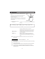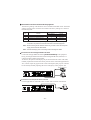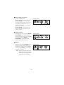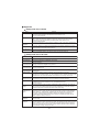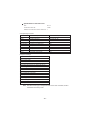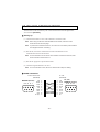
1
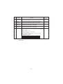
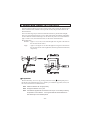
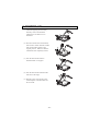
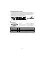
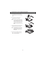
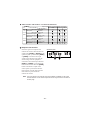
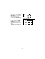
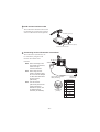
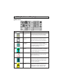
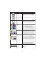
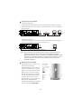
VISUAL PRESENTER
HV-8500SX
cev.fr
INSTRUCTION MANUAL
VISUAL PRESENTER
Please read this instruction manual carefully before using this Visual Presenter and
keep it for future reference.
CONTENTS
1. PART NAMES AND FUNCTIONS .................................................... 8
Appearance .................................................................................................. 8
Front Panel .................................................................................................. 8
Operation Panel .......................................................................................... 9
Rear Panel .................................................................................................. 10
Wireless Remote Contro ............................................................................. 12
2. WIRELESS REMOTE CONTROL ................................................... 13
Preparation .................................................................................................. 13
3. MOUSE ........................................................................................... 14
4. SETTING UP ................................................................................... 15
Connection to the monitor and the projector ...............................................
Connection to the analogue RGB-in terminal ........................................
Connection to the composite video-in terminal ......................................
Connection to the S video-in terminal ....................................................
Analogue RGB signal ..................................................................................
Signal allocation .....................................................................................
Pin assignment ......................................................................................
16
16
16
17
17
17
17
5. STORING THE PRESENTER ......................................................... 18
6. OPERATION PROCEDURES ......................................................... 19
Simple steps for presenting printed material ............................................... 19
Simple steps for showing transparent material, such as overhead
transparencies or slide film .......................................................................... 20
7. VARIOUS FUNCTIONS .................................................................. 21
Lighting ........................................................................................................
Zoom ...........................................................................................................
Input selection .............................................................................................
Table of Video- and Audio-in/out Terminal Selections ...........................
Output to the monitor ...................................................................................
Table of Corresponding Signals ............................................................
Electronic enlargement ................................................................................
Color/B&W selection ...................................................................................
Posi/Nega conversion .................................................................................
Image rotation .............................................................................................
Pause ..........................................................................................................
Contrast .......................................................................................................
White Balance .............................................................................................
Iris ................................................................................................................
Focus ...........................................................................................................
Auto Focus .............................................................................................
Powered Manual Focus .........................................................................
About the preset and move operation .........................................................
LCD monitor bracket socket ........................................................................
Connecting to the LCD monitor out terminal ...............................................
PC link software “Image Mate” ....................................................................
-6-
21
22
22
23
23
24
25
25
26
26
26
27
27
28
29
29
30
30
31
31
32
8. OSD (On-Screen Display) ............................................................. 33
Main menu ...................................................................................................
When the white balance is set .....................................................................
When the gamma is set ...............................................................................
When the microphone volume is set ...........................................................
When the IP address is displayed ...............................................................
33
34
34
34
34
9. NETWORK FUNCTIONS ................................................................ 36
Preparation for connection ..........................................................................
Preparation before setting up ................................................................
Connection to the network .....................................................................
Setting up of the network .......................................................................
Initialization of the network settings .......................................................
Web server functions ...................................................................................
Display of quasi-moving images ............................................................
Display of static images .........................................................................
Operation of remote control ...................................................................
FTP client function .......................................................................................
Setting up ...............................................................................................
Operation ...............................................................................................
FTP server functions ...................................................................................
telnet server functions .................................................................................
Appendix .....................................................................................................
Setting items of the network ..................................................................
Setting items of the FTP client ...............................................................
Specifications of the FTP server ............................................................
36
36
37
37
39
39
40
40
41
41
42
43
43
43
44
44
44
45
10. RS-232C SPECIFICATIONS ......................................................... 46
Setting up ....................................................................................................
Cable connection .........................................................................................
Table of the communication commands ......................................................
Data format specifications ...........................................................................
Trasnmission Command (PC Visual Presenter) .................................
Responce data format (Visual Presenter PC) ....................................
Transmission specifications ........................................................................
Connection ..................................................................................................
46
46
47
48
49
49
50
50
11. TROUBLESHOOTING HINTS ...................................................... 51
Replacement of fluorescent lamp ................................................................ 51
12. SPECIFICATIONS ........................................................................ 52
General ..................................................................................................
Network Specifications ..........................................................................
Main camera ..........................................................................................
Lighting ..................................................................................................
Supplied accessories .............................................................................
Options ..................................................................................................
-7-
52
52
53
54
54
54
1. PART NAMES AND FUNCTIONS
Appearance
3. Camera Head
12. Infrared Sensor
6. Lighting Unit Arm
5. Lighting Unit
4. Column Lock
Rerease Button
9. Carryng Handle
2. Column
Press this button
to raise/fold the
column.
6. Lighting Unit Arm
5. Lighting Unit
11. Power Switch
13. Mic Jack (MIC)
10. LCD Monitor
Bracket Socket
1. Stage
7. Front Panel
15. Scroll Mouse
8. Operation Panel
14. Wireless Remote Control
Usually, this panel is kept inside the main body.
When the PUSH part is pushed, this panel becomes
ready for operation.
Front Panel
16. Lamp Buttons 17. Zoom Buttons
18. Auto Focus Button
Name
Function
Reference Page
16.
Lamp Buttons
To turn ON/OFF the lighting.
17.
Zoom Buttons
To change the image size.
P.19, P.29
18.
Auto Focus Button
To focus automatically (One-shot auto focus).
(FOCUSFREE)
P.19, P.29
-8-
P.20, P.21
Operation Panel
20. Monitor Output Buttons
25. Freeze Button
24. Image Rotation Button
30. Focus Buttons
26. Image Transfer Button
28. Contrast Button
27. White Balance
21. Magnification Button
Button
19. Input Selection Buttons
22. Color/B&W Selection Button
29. Iris Buttons
23. Posi/Nega Conversion Button
Name
Function
Reference
Page
19.
Input Selection Buttons
To change the input line.
P.22
20.
Monitor Output Buttons
To select the signal for outputting to the NTSC/PAL monitor.
P.23
21.
Magnification Button
To double the image size.
P.25
22.
Color/B&W Selection Button To present black-and-white material, such as documents.
P.25
23.
Posi/Nega Conversion Button To show negative films.
24.
Image Rotation Button
To rotate the image. Every time this button is pressed,
the image rotates counterclockwise by 90°.
P.26
25.
Freeze Button
To freeze the image temporarily.
P.26
26.
Image Transfer Button
To save the static image file in the host (e.g., PC)
on the network.
P.43
27.
White Balance Button
Auto/ One-Push
To change the mode between AUTO and
ONE-PUSH.
P.27
28.
Contrast Button
To make characters in documents, etc. visible clearly.
P.27
29.
Iris Buttons
To adjust the brightness of the screen.
P.28
30.
Focus Buttons
To adjust focus (powered).
-9-
P.20, P.26
P.29, P.30
Rear Panel
31. Power Cord
Receptacle
[AC IN]
33. 12VDC Out Terminal 35. RS-232C Terminal 40. Audio-out Terminal 43. Audio-in Terminal 1
[DC12V]
[RS-232C]
41. Video-in Terminal 1
AUDIO
(L/R)1
AC IN
POWER
ON
DC12V
RS-232C
VIDEO
L AUDIO R
S-VIDEO
RGB OUT
RGB1
RGB2
AUDIO
(L/R)2
OFF
Ethernet
32. Power Switch
[POWER]
USB
MOUSE
OUTPUT
37. USB Terminal [USB]
ABCD
INPUT
42. Video-in Terminal 1
34. Mouse Terminal [MOUSE] 38. Analogue RGB-out Terminal
[OUTPUT.RGB OUT]
39. Vide-out Terminal
44. Audio-in Terminal 2
.
36. Ethernet Terminal
[OUTPUT S-VIDEO/VIDEO]
[Ethernet]
S-Video (mini DIN 4P), Composite video (RCA pinjack) 45. DIP Switch
Name
Function
Reference
Page
31. Power Cord Receptacle [AC IN] Connected to the power cord connector.
32. Power Switch [POWER] To turn ON/OFF the power supply.
P.19
33. 12VDC Out Terminal
[DC12V]
P.31
To output 12VDC and the image. Can be connected to
the LCD monitor (LM-5011N) (option) by using
the LCD monitor connection cable (attached).
P.19
Note: Do not connect the equipment other than LM-5011N.
34. Mouse Terminal [MOUSE] To connect the mouse (supplied accessory).
To connect the RS-232C cable when controlling the
35. RS-232C Terminal
main unit from the PC.
[RS-232C]
P.14
36. Ethernet Terminal [Ethernet] To connect the Ethernet cable when the network function is used.
To connect the USB cable (attached) to transfer the image or
37. USB Terminal [USB]
P.37
P.46
Note: This terminal cannot be used when the USB terminal
is used to control the main unit.
control the main unit with the CD-ROM “Image Mate” (attached).
P.32
Note: This terminal cannot be used when the RS-232C is
used to control the main unit.
38. Analogue RGB-out Terminal Image is output when this terminal is connected to RGB input
equipment (e.g., liquid crystal projector, multi-sync monitor).
[OUTPUT.RGB OUT]
P.23
39. Vide-out Terminal
Image is output when these terminals are connected
[OUTPUT.S-VIDEO/VIDEO] to the NTSC/PAL monitor (e.g., TV monitor).
S-Video (mini DIN 4P)
Composite video (RCA pinjack)
P.23
Audio signal is output when this terminal is connected
to audio-in equipment.
P.23
40. Audio-out Terminal
- 10 -
Name
Function
Reference
Page
P.22, P23
41. Video-in
Terminal 1
Video signal from this terminal is output through the analogue
RGB-out terminal when the input selection is set at RGB1.
42. Video-in
Terminal 2
Video signal from this terminal is output through the analogue
RGB-out terminal when the input selection is set at RGB2.
P.22, P23
43. Audio-in
Terminal 1
Audio signal from this terminal is output through the audio-out
terminal when the input selection is set at RGB1.
P.22, P23
44. Audio-in
Terminal 2
Audio signal from this terminal is output through the audio-out
terminal when the input selection is set at RGB2.
P.22, P23
45. DIP Switch
The functions can be switched as follows:
[A] key: To switch the resolution of video output through the RGB-out terminal [RGB OUT].
. SXGA . XGA
[B] key: To switch the TV output.
. NTSC
. PAL
[C] key: To switch the screen size of the TV output.
. Over scan . Under scan
[D] key: To initialize the setting of the network function to its factory setting.
. Normal operation . Initialization
Key alignment and functions:
A
B
C
D
0
SXGA
NTSC
Over scan
Normal operation
1
XGA
PAL
Under scan
Initialization
Note: Before switching the DIP switch key, be sure to turn OFF the power supply to
the Presenter.
- 11 -
Wireless Remote Control
IRIS OPEN
LAMP
IRIS CLOSE
MOVE
IRIS NORMAL
PRESET
FOCUS NEAR
FOCUS FAR
46. [IRIS OPEN]
54. [LAMP]
47. [IRIS CLOSE]
55. [MOVE]
48. [IRIS NORMAL]
56. [PRESET]
49. [FOCUS NEAR]
50. [FOCUS FAR]
TELE
WIDE
ZOOM
51. [ZOOM TELE]
52. [ZOOM WIDE]
INPUT
AF
53. [INPUT]
57. [AF]
Button Name
Function
Reference
Page
46.
IRIS OPEN
To open the AUTO iris.
P.28
47.
IRIS CLOSE
To close the AUTO iris.
P.28
48.
IRIS NORMAL
To reset the AUTO iris to the initial value.
P.28
49.
FOCUS NEAR
To move the focus near.
P.29, P.30
50.
FOCUS FAR
To move the focus far.
P.29, P.30
51.
ZOOM TELE
To zoom in.
P.19, P.22,
P.29
52.
ZOOM WIDE
To zoom out.
P.19, P.22
53.
INPUT
To change the input system.
P.22
54.
LAMP
To turn ON/OFF the lamp.
P.20, P.21
55.
MOVE
To call the operating status of the Presenter
saved in [PRESET].
56.
PRESET
To save the operating status of the Presenter.
57.
AF
To focus automaticaly.
- 12 -
P.30
P.30
P.19, P.29
2. WIRELESS REMOTE CONTROL
30
30
30
30
30
30
30
30
Point the infrared emitting part of the wireless remote control unit at the infrared sensor
of the Visual Presenter, located on the top of the column, and press the button for the
desired function.
The receivable range may be narrowed when the Presenter is placed under sunlight,
near an inverter fluorescent lamp or in any other unfavorable surroundings. Depending
on the conditions of fluorescent lamps, etc. the sensor may fail to receive the infrared
light. In such a case, relocate the Presenter, or take other countermeasures.
Receivable range
Distance : Approx. 7 m (23 ft.) or less from the light receiving area to the front of
the wireless remote control
Angle : Approx. 30° degrees or less from the light receiving area to the front of
the wireless remote control rightward, leftward, upward and downward,
respectively
Preparation
Remove the battery case cover by pressing downward on the [ OPEN] mark part in
the direction as indicated by the arrow. Install 2 pcs of batteries (type R03, AAA) into
the case in the direction as indicated there.
Note: Install the batteries with the right polarity.
Note: Change the batteries once a year.
Note: The batteries supplied with the Presenter are only for use in initially confirming
the operation of the Presenter. It is not guaranteed that these batteries can
work effectively for the indicated period.
- 13 -
3. MOUSE
Connect the mouse to the mouse terminal on the rear
panel.
The mouse can control the display and operation of
the OSD Menu screen, mouse pointer and the
Electronic enlargement.
When the left button of the mouse is clicked, the OSD
menu and the pointer are displayed. Set each function
with the mouse.
Mouse
Right button
Left button
Center button
Mouse wheel
The mouse is operated as follows:
• Left button........................ To display or clear the pointer and menu alternately by
clicking.
The pointer
is displayed
Click
The menu Click
is displayed
The menu
is cleared
Click
The pointer
is cleared
Click
To set each item on the OSD menu while the menu is
in display. When the image is in electronic
enlargement, the image scroll function is activated by
dragging the mouse while holding down this button.
• Mouse wheel ............... To scroll the enlarged screen up/down when the image is in
electronic enlargement.
• Right button ..................... When this button is clicked when the pointer is in
display, the electronic image enlargement function is
activated with the position indicated by the pointer as a
center.
Note: When the right button is clicked on the OSD menu, the menu functions are
given priority.
Reference Page
· Electronic enlargement
P.25
Note: When using the mouse, connect the mouse before turning ON the power supply
to the Presenter.
Note: Use the attached mouse.
If a mouse on the market is used, the normal operation cannot be guaranteed.
Note: The OSD display is assumed to be used for large projection sizes with a
projector or the like. Therefore, the display on a monitor or a TV on hand may
not be hard to see.
- 14 -
4. SETTING UP
(1) Unfold the lighting unit arms fully
until they come to the deadend.
Unfold arm 1 and then arm 2 as
illustrated.
(2) Press the column lock release button,
and raise the column until the column
lock release button returns to the
original position. Make sure that the
column has been completely locked.
(3) Turn the main camera head as
illustrated until it is stopped.
(4) Turn the main camera head until the
lens faces to the stage.
(5) Plug the power cord into the power
cord receptacle of the Presenter and
the AC outlet.
- 15 -
Connection to the monitor and the projector
The following settings of the Presenter can be switched with the DIP switch. Switch the
settings according to the connection environment. The factory settings are as shown in
the following table:
Key
A
B
C
D
Initial setting
Function
Key selection
0
0
0
0
To switch the image output
To switch the TV output method
To switch the TV output screen size
To initialize the network function settings
Content
SXGA output
NTSC
Over scan
Normal operation
Note: Be sure to turn OFF the power supply to all equipment before making any
connections to protect the Presenter and all the connected equipment.
Note: When switching the I/O selection switch key, be sure to turn OFF the power
supply to the Presenter beforehand.
Note: Hold the cable plug when connecting or disconnecting the cables.
Connection to the analogue RGB-in terminal
Connect the analogue RGB-out terminal [OUTPUT·RGBOUT] to the equipment
having an analogue RGB-in terminal with the analogue RGB cable (attached) or a
connection cable available on the market.
At this time, the position of the display may be deviated from the center. If deviated,
manually adjust the horizontal and vertical positions on the connected equipment side.
Also, vertical stripes may appear on the screen of the liquid crystal projector. That can
be alleviated by manually adjusting the dot clock frequency on the projector side.
Liquid crystal projector
AUDIO
(L/R)1
AC IN
POWER
ON
DC12V
RS-232C
VIDEO
S-VIDEO
L AUDIO R
RGB OUT
RGB1
RGB2
Monitor
AUDIO
(L/R)2
OFF
Ethernet
USB
MOUSE
OUTPUT
INPUT
Connection to the composite video-in terminal
Use the supplied RCA video/audio cable or a BNC cable available on the market.
AUDIO
(L/R)1
AC IN
POWER
ON
DC12V
RS-232C
VIDEO
S-VIDEO
L AUDIO R
RGB OUT
RGB1
RGB2
OFF
Ethernet
USB
MOUSE
OUTPUT
- 16 -
INPUT
AUDIO
(L/R)2
Monitor
Connection to the S video-in terminal
Connect the S video-out terminal (mini DIN 4P) of the Presenter to the S video-in
terminal of the TV/video monitor. For the S video mode, use an S video connection
cable available on the market. If the equipment to be used is provided with a Y/C
separate connector, a conversion adapter is necessary.
Monitor
AUDIO
(L/R)1
POWER
AC IN
ON
DC12V
RS-232C
VIDEO
L AUDIO R
S-VIDEO
RGB OUT
RGB1
RGB2
AUDIO
(L/R)2
OFF
Ethernet
USB
MOUSE
OUTPUT
INPUT
Analogue RGB signal
Signal allocation
5
4
3
2
1
Video signal
10
9
8
7
6
Analogue 0.7V(p-p) 75
terminated
Horizontal synchronized signal TTL level (positive/negative polarity)
15 14 13 12 11
Vertical synchronized signal
TTL level (positive/negative polarity)
DSUB 15P shrink terminal (Female)
Pin assignment
Pin No.
Name
Pin No.
Name
Pin No.
Name
1
2
3
4
5
Video signal (Red)
Video signal (Green)
Video signal (Blue)
N.C
GND
6
7
8
9
10
GND (Red)
GND (Green)
GND (Blue)
N.C
GND
11
12
13
14
15
GND
N.C
Horizontal synchronized signal
Vertical synchronized signal
N.C
- 17 -
5. STORING THE PRESENTER
(1) Turn OFF the power switch, and
unplug the power cord and the video
cable.
(2) Turn the main camera head as
illustrated until it is stopped.
Note: Be sure to set the camera head
in the illustrated position before
storing. Storing the main camera
head in any other position may
damage the stage surface or the
lens.
(3) Press the column lock release button,
and fold down the main column.
Note: The illustration shows the right
storage position of the column.
Never apply excessive force to
the column.
(4) Fold down the lighting unit arms 5
and 6. Be sure to fold down arm 5
first as per the illustration.
- 18 -
6. OPERATION PROCEDURES
Simple steps for presenting printed material
(1) Turn ON the power switch.
Note: Before turning ON the power
switch, connection to the
monitor should have been
completed.
Note: When the power switch is
turned ON, the lighting unit
lights up.
Note: If the power switch is turned
ON immediately after being
turned OFF, the Presenter may
not operate. For restarting,
turn OFF the Presenter and
wait several seconds then turn
ON.
(2) Place the object on the stage. Adjust
the image size according to the
object size using the zoom buttons
([TELE] / [WIDE]) on the front
panel or the zoom buttons ([TELE]
/ [WIDE]) on the wireless remote
control, while watching the image
on the TV monitor.
(3) Press the auto focus button [AUTO
FOCUS] on the front panel or the
auto focus button [AF] on the
wireless remote control.
Note: The auto focus function works
up to a height of approx. 10cm
(3.9 in) above the stage
surface when the zoom button
[TELE] is set to the maximum.
- 19 -
Front panel
Wireless remote control
TELE
ZOOM
WIDE
Front panel
Wireless remote control
INPUT
AF
Simple steps for showing transparent material, such as overhead
transparencies or slide film
Front panel
(1) Press the base button [BASE] on
the front panel or the lamp button
[LAMP] on the wireless remote
control to light up the base light
(transparent lighting unit) built in
the stage.
Wireless remote control
IRIS OPEN
(2) To present a nega film, press the
posi/nega conversion button [POSI
/ NEGA] on the operation panel to
change the mode to [N] (Negative).
LAMP
Operation panel
Front panel
(3) To turn OFF the base light, press
the base button [BASE] on the
front panel or the lamp button
[LAMP] on the wireless remote
control again.
Wireless remote control
IRIS OPEN
- 20 -
LAMP
7. VARIOUS FUNCTIONS
Lighting
The upper lighting unit for presenting
material such as printed matter and 3-D
objects, and the baselight for presenting
transparent material, such as slide, and
negative films, are built in to the
Presenter.
When the lamp button [LAMP]
( [UPPER] / [BASE] ) on the front
panel or the lamp button [LAMP] on the
wireless remote control is pressed, the
fluorescent lamp lights up in 1 to 3
seconds.
Every time the lamp button [LAMP] on
the wireless remote control is pressed,
lighting is switched in a cycle of the
lighting unit lights up the base
light lights up the base light
goes out.
The lighting unit lights up when the
power supply is turned ON.To turn OFF
the lamp, press the button for the
respective lamp.
Front panel
Wireless remote control
IRIS OPEN
LAMP
Note: It is impossible to have the upper lighting unit and the baselight lit up together.
Note: To obtain a sharp image with good color rendering, it is sometimes necessary to
use the upper lighting unit.
- 21 -
Front panel
Zoom
Press the zoom button [TELE] on the
front panel or wireless remote control,
and the image will gradually be enlarged.
Wireless remote control
TELE
ZOOM
WIDE
Front panel
Press the zoom button [WIDE] on the
front panel or
wireless remote control, and the image
will gradually be reduced.
Wireless remote control
TELE
ZOOM
WIDE
Input selection
The respective images from two different
sources such as a PC and an Elmo
Presenter "HV-100XG" can be alternately
presented on a TV by selecting the source
by pressing the desired input selection
buttons without changing the cable
connections. The input can be switched
by pressing the input select button
[RGB1] or [RGB2] on the operation
panel or the input select button [INPUT]
on the wireless remote control. The
lighting of the indicator lamp indicates
which input is now selected.
Every time the input selection button
[INPUT] on the wireless remote control
is pressed, input is switched in a cycle of
the Main
RGB1
RGB2.
Input selection is possible as shown in the
following table:
- 22 -
Operation panel
Wireless remote control
INPUT
AF
Table of Video- and Audio-in / out Terminal Selections
Output signal Video-out Terminal
RGB
Input
Main
Unit
Audio-out Terminal
L
R
Main camera video signal
Microphone
Monaural
Main camera video signal
RGB1
External video signal 1
RGB1
External audio signal 1
Stereo 1 (L/R)
Microphone
Monaural
Main camera video signal
RGB2
External video signal 2
RGB2
External audio signal 2
Stereo 2 (L/R)
Microphone
Monaural
Output to the monitor
Select the signal to be output to the
NTSC/PAL monitor. When the monitor
output button [RGB1] or [RGB2] on the
operation panel is pressed while [RGB1]
or [RGB2] is selected for the input
selection, the indicator lamp lights up,
and the image from the equipment
connected to the external input terminal
[RGB1] or [RGB2] is presented on the
NTSC/PAL monitor. When the [MAIN]
button of the monitor output on the
control panel is pressed, the indicator
lamp lights up, and the image from the
main camera is presented on the
NTSC/PAL monitor.
Operation panel
Note: The input signals to the external input terminal RGB1 and RGB2 can be output
to the NTSC/PAL monitor if their frequencies are among the listed in the table at
the next page.
- 23 -
Table of Corresponding Signals
Frequency
Signal
Mode name
VGA1
VGA2
VGA3
VGA@60Hz
VGA@72Hz
VGA@75Hz
VGA@85Hz
SVGA@56Hz
SVGA@60Hz
SVGA@72Hz
SVGA@75Hz
SVGA@85Hz
XGA@60Hz
XGA@70Hz
XGA@75Hz
XGA@85Hz
SXGA1
SXGA2
SXGA3
SXGA@60Hz
SXGA@75Hz
SXGA@85Hz
UXGA@60Hz
UXGA@65Hz
UXGA@70Hz
UXGA@75Hz
UXGA@85Hz
Mac 13
Mac 16
Mac 19
Mac 21
PC98
Horizontal
kHz
37.861
37.861
37.972
31.469
37.861
37.500
43.269
35.156
37.879
48.077
46.875
53.674
48.363
56.476
60.023
68.677
67.500
60.000
85.938
63.981
79.976
91.146
75.000
81.250
87.500
93.750
106.250
35.000
49.725
60.241
68.682
24.825
Vertical
Hz
85.080
85.080
85.039
59.940
72.809
75.000
85.008
56.250
60.317
72.188
75.000
85.061
60.004
70.069
75.029
84.997
75.000
60.000
85.002
60.020
75.025
85.024
60.000
65.000
70.000
75.000
85.000
66.667
74.550
74.927
75.062
56.420
Pixel clock
MHz
31.500
31.500
35.500
25.175
31.500
31.500
36.000
36.000
40.000
50.000
49.500
56.250
65.000
75.000
78.750
94.500
108.000
108.000
148.500
108.000
135.000
157.500
162.000
175.500
189.000
202.500
229.500
30.240
57.283
80.000
100.000
21.052
- 24 -
Resolution
(Number of lines)
Horizontal
640
640
720
640
640
640
640
800
800
800
800
800
1024
1024
1024
1024
1152
1280
1280
1280
1280
1280
1600
1600
1600
1600
1600
640
832
1024
1152
640
Vertical
350
400
400
480
480
480
480
600
600
600
600
600
768
768
768
768
864
960
960
1024
1024
1024
1200
1200
1200
1200
1200
480
624
768
870
400
Polarity of
the synchronized signal
(P: Positive, N: Negative)
HV
P/N
N/P
N/P
N/N
N/N
N/N
N/N
P/P
P/P
P/P
P/P
P/P
P/P
N/N
N/N
P/P
P/P
P/P
P/P
P/P
P/P
P/P
P/P
P/P
P/P
P/P
P/P
P/P
N/N
N/N
N/N
N/N
Electronic enlargement
To double the image.
To double the central part of the image,
press the button [MAGNIFICATION] on
the operation panel. When double
magnification is selected, the indicator
lamp lights up.
The image can be enlarged only within
the shooting area of the main camera.
The mouse can be operated as follows:
Operation panel
• Left button ......................... To scroll the image according to the dragging of the
mouse while holding down the left button.
• Mouse wheel................... To scroll up/down the enlarged screen.
• Right button ...................... To turn ON/OFF the double enlargement.
Note: When the electronic enlargement is tried while the mouse pointer is in display,
since the left button of the mouse is limited to the scroll function, the mouse
pointer and the OSD cannot be turned ON/OFF. To turn ON/OFF the mouse
pointer and the OSD, turn OFF the electronic enlargement.
Color / B&W selection
To present the B&W (Black&White)
material such as documents. Sharper
image with no color blur on the monitor
can be produced. Set to color mode for
normal use.
Press the color/B&W selection button
[COLOR / B&W] on the operation
panel, the indicator lamp lights up and
the mode changes to B&W mode.
When the color/B&W selection button
[COLOR / B&W] is pressed again, the
indicator lamp goes out and the normal
(COLOR) mode is resumed.
- 25 -
Operation panel
Posi / Nega conversion
To show a negative film.
Press the posi/nega conversion button
[POSI / NEGA] on the operation panel
or wireless remote control, the indicator
lamp lights up and the image will be
converted accordingly.
When the posi/nega conversion button
[POSI / NEGA] is pressed again, the
indicator lamp goes out and the normal
mode is resumed.
Operation panel
Image rotation
When the image rotation button [IMAGE
ROTATION] on the operation panel is
pressed, the image rotates. Every time the
image rotation button [IMAGE
ROTATION] is pressed, the image
rotates counterclockwise by 90°.
Operation panel
Pause
When the freeze button [PAUSE] on the
operation panel is pressed, the image
from the main camera freezes. When the
freeze button [PAUSE] is pressed again,
the freeze is canceled.
Note: When the image remains frozen,
the functions such as color/B&W
selection are not reflected on the
output from the main camera.
- 26 -
Operation panel
Contrast
To present the material with a little half
tone such as documents.
Images with sharp characters and lines
contrasty with background can be
obtained.
When the contrast button [CONTRAST]
on the operation panel is pressed, the
indicator lamp lights up, and the image
becomes contrasty.
When the contrast button [CONTRAST]
is pressed again, the indicator lamp goes
out, and the image is reset to the normal
condition.
Operation panel
White Balance
The camera of the Presenter
Operation panel
automatically adjusts the shooting color
balance (AUTO mode). However,
depending on the color arrangement of
document or the like, this color balance
may be lost. In such case, shoot the stage
surface, and press the white balance
button [WHITE BALANCE] on the
operation panel. Then, the mode is
switched to the ONE-PUSH mode, the
indicator lamp blinks and then lights up,
and the white balance is fixed.
When the white balance button [WHITE BALANCE] is pressed again, the indicator
lamp goes out, and the mode returns to the AUTO mode.
AUTO .............To set the white balance in the auto follow mode (initial setting).
ONE-PUSH....To set the push-set white balance. By pressing the button [WHITE
BALANCE], the white balance for the then color temperature is
fixed.
Note: The automatically followed color temperature ranges from approx. 3000k to
8000k.
Note: When the white balance is set to the MANUAL mode on the OSD, the white
balance is fixed, and the indicator lamp remains lighting. When the white
balance button [WHITE BALANCE] on the operation panel is pressed while the
indicator lamp is lighting, the indicator lamp goes out, and the mode is switched
to the AUTO mode.
- 27 -
Iris
To adjust the Auto iris level of the lens.
Press the iris button [OPEN] on the
operation panel or the iris open button
[IRIS OPEN] on the wireless remote
control, and the iris will open.
Press the iris button [CLOSE] on the
operation panel or the iris close button
[IRIS CLOSE] on the wireless remote
control, and the iris will close.
Press the iris normal button [IRIS
NORMAL] on the wireless remote
control, and the initial setting will be
resumed.
Note: When the image looks dark,
adjust the brightness with iris
control.
- 28 -
Operation panel
Wireless remote control
IRIS OPEN
LAMP
IRIS CLOSE
MOVE
IRIS NORMAL
PRESET
Focus
Auto Focus
Front panel
Press the auto focus button [AUTO
FOCUS] on the front panel or the auto
focus button [AF] on the wireless remote
control, and the auto-focus will be
Wireless remote control
activated.
INPUT
AF
While the auto-focus is in operation, the
indicator lamp on the front panel blinks
until the object is brought into focus.
The Presenter features a one-push auto
Front panel
focus function. Once focusing is
completed, the auto focus function is
released, and the focused position
maintains unchanged (FOCUSFREE).
To obtain sharper image, zoom in on the
Wireless remote control
object by pressing the zoom button
TELE
ZOOM
WIDE
[TELE] on the front panel or wireless
remote control and press the auto-focus
botton.
However, the objects listed below may
not be brought into focus in the auto
focus mode. In these cases, use the
manual focus mode.
• Objects bearing little contrast
• Objects with fine repeated patterns, such as lateral stripes and cross stripes
• Objects glittering or reflecting strong light
• Objects with bright background, or excessive contrast
• Objects in a dark picture plane
• Objects located near and far away at the same time
• Objects in motion
If the focus button [NEAR] or [FAR] on
the front panel or the focus button
[FOCUS NEAR] or [FOCUS FAR] on
the wireless remote control is pressed
during the auto focus, the auto focus will
be released.
Note: The auto focus function works
up to a height of approx. 10cm
(3.9 in) above the stage surface
when the zoom button [TELE] is
set to the maximum.
- 29 -
Operation panel
Wireless remote control
FOCUS NEAR
TELE
FOCUS FAR
ZOOM
WIDE
Powered Manual Focus
To focus on specific part of the material,
such as 3-D material. Press the focus
button [NEAR] or [FAR] on the
operation panel or the focus button
[FOCUS NEAR] or [FOCUS FAR] on
the wireless remote control.
Note: The auto focus functions up to
approx. 10cm (3.9 in.) above the
stage surface (with the close-up
lens attached).
Operation panel
Wireless remote control
FOCUS NEAR
TELE
FOCUS FAR
ZOOM
WIDE
About the preset and move operation
The Presenter has a function of saving its
operation status (Preset).The preset
function is read with the move button
[MOVE] on the wireless remote control.
The operation status that can be saved
includes:
• Preset zoom angle of view
• Adjustment status of AUTO iris level
• White balance status
• ON/OFF of apreture
• Status of gamma
• Lighting status
• Microphone level
Wireless remote control
IRIS CLOSE
MOVE
1. How to move
When the move button [MOVE] on the wireless remote control is pressed, the
Presenter is set to the preset status.
2. How to preset
When the preset button [PRESET] on the wireless remote control is pressed, the
current status of the Presenter is saved.
- 30 -
LCD monitor bracket socket
The LCD monitor bracket socket is used
for attaching an LCD monitor (optional)
with an LCD monitor bracket (optional).
LCD Monitor (optional)
LCD Monitor bracket (optional)
LCD Monitor bracket socket
Connecting to the LCD monitor out terminal
The LCD monitor (LM-5011N) can
be connected by using the LCD
monitor out terminal of the
Presenter.
Note: When connecting to the
LCD monitor out terminal,
confirm the right
connection direction.
DC IN 12V
VIDEO IN
Note: When using the LCD
monitor connection cable,
do not use the AC adapter
or video cable attached to
the LCD monitor
(LM-5011N).
LCD monitor connection
cable (accessory)
Note: The LCD monitor
(LM-5011N) and the LCD
monitor bracket are
available on option, and
not attached to this
Presenter (HV-8000SX).
9 8
7
6 5 4 3
2 1
Mini DIN 9P
(Female)
- 31 -
LCD monitor
out terminal
1
VIDEO OUT
2
GND
3
NC
4
NC
5
NC
6
NC
7
+12V
8
GND
9
CONT.
PC link software “Image Mate”
When the “Image Mate” is installed in the PC, the following operations are available:
• Image data transfer to the PC
• Operation of the Presenter by the PC
For details, refer to the installation manual of “Image Mate” and “manual.pdf” in the
CD-ROM.
- 32 -
8. OSD (On-Screen Display)
Main menu
Icon
Name
Function
Upper light
ON/OFF
To turn ON/OFF the upper light.
When the Presenter is turned ON, the upper
light remains at the previously saved settings.
Base light
ON/OFF
To turn ON/OFF the base light.
When the Presenter is turned ON, the base
light remains at the previously saved settings.
Color/B&W
selection
To switch the selection of the color/B&W
of the screen. When the Presenter is turned ON,
the color/B&W selection remains at the
previously saved settings.
Posi/Nega
selection
To switch the selection of the positive/negative
of the screen. When the Presenter is turned ON,
the positive/negative selection remains at the
previously saved settings.
Image rotation
To rotate the image counterclockwise by 90 .
When the Presenter is turned ON, the image
rotation remains set at 0 .
Freeze
To switch the selection of the static/moving
image. When the Presenter is turned ON, the
static/moving image selection remains at the
previously saved settings.
Aperture
selection
To switch the modulation (edge emphasis) of the
image. When the Presenter is turned ON, the
image modulation remains at the previously
saved settings. The factory setting is “ON.”
- 33 -
Icon
When the
white balance
is set
Name
Function
Pointer
To change the color and shape of the pointer on
the screen. Every time the left button of the
mouse is clicked, the icon pointer is switched in
order of “White arrow Blue arrow Yellow arrow
Red arrow” and “White line Blue line Yellow line
Red line”.
Status saving
To save each status of the current aperture, lighting,
white balance, preset zoom angle of view, gamma,
auto iris level and microphone level. The settings
save here are reflected on the Presenter when the
Presenter is turned ON the next time.
Initialization
To reset the Presenter to the status of the factory
settings
Focus
NEAR/FAR
To adjust the focus of the lens.
Auto Focus
To focus the lens automatically.
Zoom
TELE/WIDE
To adjust the zoom of the lens.
Iris
Close/Open
To adjust the auto iris level of the lens.
When the
gamma is
set
When the
microphone
volume is set
- 34 -
When the IP
address is
displayed
Icon
Name
Function
White balance
To display the White Balance Adjustment menu.
When the left button of the mouse is clicked
again, the White Balance Adjustment menu is
closed.
Auto
To set the white balance in the AUTO FOLLOW
mode (initial setting).
One-push
To set the push-set white balance. When the left
button of the mouse is clicked, the white balance
for the then color temperature is fixed.
Manual
To set the white balance with <RED>, <GREEN>
and <BLUE>. Adjust the white balance by
clicking the left button of the mouse on the
direction buttons beside the volume bar.
<RED>…To adjust the red component (1-99).
<GREEN>…To adjust the green component (1-99).
<BLUE>…To adjust the blue component (1-99).
Gamma adjustment To switch the gamma setting value (0(1.0) /
(0-7)
1(0.9) / 2(0.8) / 3(0.7) / 4(0.6) / 5(0.5) / 6(0.4) /
7 (0.3)). When the Presenter is turned ON, the
gamma setting value remains at the previously
saved settings. The factory setting is “4 (0.6).”
Volume adjustment Volume adjustment (0-63) To adjust the audio
(0-63)
volume from the microphone terminal.
When the Presenter is turned ON, the volume
adjustment remains at the previously saved settings.
When the left button of the mouse is clicked on
this icon, the volume bar is displayed. Adjust the
audio volume by clicking the left button of the
mouse on the direction buttons beside the volume
bar. When the left button of the mouse is clicked
on the icon of the volume adjustment again, the
volume bar is closed. The factory setting is “50.”
IP address
To display the IP address.
When the left button of the mouse is clicked on
this icon, the IP address of the Presenter is
displayed.
- 35 -
9. NETWORK FUNCTIONS
By connecting this Presenter to the network using Ethernet (10BASE-T/100BASE-TX),
the following functions are made available from the host (e.g., PC) on the network:
• Web server functions – Displaying quasi-moving images, displaying static images
and operating remote control through the Web browser.
• FTP client functions – Saving image files in the remote host by using the image
transfer button [IMAGE TRANSFER].
• FTP server functions – Transferring image files.
• telnet server functions – Operating remote control and acquiring status data.
Note: It is not assured that this Presenter can be connected to all units on the network.
Note: The applicable Web browsers are Internet Explorer 4.0 and newer and
Netscape 4.7 and newer. For any other browser, consult your dealer or an
authorized ELMO service center.
Preparation for connection
Before connecting the Presenter to the network for use, the network must be set up (e.g.,
IP address).This Presenter provides two procedures for setting up the network as
follows:
• Connecting the Presenter from the host on the network through the Web browser.
• Connecting the Presenter from the host on the network through telnet.
Here, the setup procedure using the Web browser is described.
For the setup procedure using telnet, consult your dealer or an authorized ELMO service
center.
Preparation before setting up
Before starting the setup, specify the IP address and subnet mask to be set up in the
Presenter. For the IP address and subnet mask to be specified, ask the administrator
of the network to be used.
This Presenter has been factory set on the network as follows:
IP address
192.168.0.100
Subnet mask
255.255.255.0
If the network address of the network to be used is not 192.168.0.0 or if there is any
other host with the IP address 192.168.0.100 is already in operation on the same
network, this Presenter cannot be connected to the network for setup. In this case, a
network with the IP address 192.168.0.0 must be configured with this Presenter and
the host for setting up this Presenter. Prepare a host having the IP address
192.168.0.X (X: 1~254, excluding 100) and the subnet mask 255.255.255.0, and
connect such host to the Presenter.
Reference Page
• Accessing the network
- 36 -
P.36, P.37, P38
Connection to the network
• Connection using HUB
Connect the Ethernet terminal (RJ-45) of the Presenter to the HUB port with an
Ethernet straight cable (UTP Category 5). For the HUB port, use a port other than
the cascade port.
DC12V
RS-232C
VIDEO
L AUDIO R
S-VIDEO
Ethernet
USB
MOUSE
RGB OUT
OUTPUT
RGB1
RGB2
AUDIO
(L/R)2
HUB
Host
Host
ABCD
INPUT
Ethernet straight cable
• Connection to one host
Connect the Ethernet terminal (RJ-45) of the Presenter to the Ethernet terminal of
the host with an Ethernet cross cable (UTP Category 5).
DC12V
RS-232C
VIDEO
L AUDIO R
S-VIDEO
Ethernet
USB
MOUSE
RGB OUT
OUTPUT
RGB1
RGB2
Host
AUDIO
(L/R)2
INPUT
ABCD
Ethernet cross cable (accessory)
Note: Upon connection of this Presenter to other unit on the network through the
Ethernet terminal, the communication protocol is adjusted automatically
between the Presenter and the connected unit to 10BASE-T/100BASE-TX and
HDX/FDX (i.e., “automatic negotiation”). Therefore, this Presenter may not be
properly connected to some units on the network that do not comply with
automatic negotiation.
Setting up of the network
• Start the Web browser from the host
connected to the Presenter.
• Enter the IP address or host name (if
allocated) of the Presenter, following
[http://], in the address column of the
Web browser provided for entering
the URL to be opened. For example,
enter the IP address of this Presenter
as “http://192.168.0.100/,” since it
has been factory set to 192.168.0.100.
• When the HV-800SX/8000SX/
8500SX page is displayed in the Web
browser, click the link [SET UP].
- 37 -
• Then, the Configurations page is displayed.
Confirm the settings, and click the link
[Network Configuration].To display the
Network Setting Input page, the
authentication by the login password is
required. When the entry of the password is
requested, enter [root] for the user name and
enter the password set at the Network Setting
Input page. No password has been factory set.
When the Presenter remains in the factory set
condition, enter no password.
• When the Network Setting Input page is
displayed, change the set values according to
the environment of the network to be used. To
reset the changed set values to the original set
values, click the clear button [CLEAR].
• When all items have been set, click the submit button [SUBMIT].
When the message “The saving of the setup was completed. Please restart.” is
displayed, the setting up of the network is completed. Then, turn OFF the power
supply. The set values are effective as of the time when the power supply is turned
ON the next time.
If the message “Incorrect value of setting exists. Please set up again.” is displayed
when the submit button [SUBMIT] is clicked, there is an incorrect value entered for
setting. Go back to the Network Setting Input page and redo the setting.
Reference Page
· Appendix: Setting items of the network
P.44
Note: If there are more than one unit with the same IP address on the network, a
disorder would be caused to the network. Therefore, set the IP address
carefully.
Note: Once the submit button [SUBMIT] is clicked, do not turn OFF the power supply
until the next screen is displayed. Otherwise, the set values will be destroyed
and connection from the network will be disabled. If the connection is disabled,
reset the settings to the factory settings by referring to “Initialization of Network
Settings” in the next section, and the redo the setting.
- 38 -
Initialization of the network settings
If the connection from the network is disabled due to destruction of the network
settings or disremembering of the set value, reset the settings to the factory settings
by using the following procedure and then redo the settings:
• If the Presenter is in connection to the network, disconnect the Presenter from the
network.
• In the power supply OFF state, lower the [D] key of the DIP switch key on the
backside of the Presenter to [1].
• Turn ON the power supply, and wait for approx. 10 seconds.
• Turn OFF the power supply, and return the [D] key of the DIP switch to [0].
• Turn ON the power supply again. Then, the network settings and the FIP client
settings are reset to the factory settings.
Note: Ensure that the [D] key of the DIP switch is returned to [0] after the initialization.
If the key remains in the [1] position, the connection from the network is
disabled.
Web server functions – Displaying quasi-moving images,
displaying static image and operating remote control through the
Web browser
When the Presenter is connected from the Web browser, quasi-moving images can be
displayed, static images cab be displayed, and remote control can be operated. To
connect the Presenter from the Web browser, enter the IP address or host name (if
allocated) of the Presenter, following [http://], in the address column of the Web
browser provided for entering the URL to be opened. Then, the HV-800SX/8000SX/
8500SX page is displayed. Click the desired link there. Then, the selected function can
be used.
Note: Even if the image is tried to be electronically magnified, rotated or frozen by
operating this Presenter, the image output to the network is not affected by this
operation.
- 39 -
Display of quasi-moving images
When the link [LIVE] is clicked at the
HV-800SX/8000SX/8500SX page,
another window opens, and a quasimoving live image is displayed.
However, to display quasi-moving
images, Java and JavaScript must have
been set enabled. If the Presenter is
used in the environment where Java or
JavaScript are not set enabled, click the
link [REFRESH]. Then, a page that
renews static images at specified
intervals is be displayed.
Quasi-moving images can be displayed simultaneously at up to 15 clients. If more
clients access the Presenter, the screen displays the message “LIVE mode already has
the limited number of access. Please wait or use REFRESH!”
The frame rate of the quasi-moving image is max. 3.75 frames per second. However,
the frame rate depends on the processing capacity of the host, the network
environment, the number of connections units, etc.
Note: If the power supply to the Presenter is turned OFF while the quasi-moving
image is in display, the host displaying the quasi-moving image may, depending
on the Web browser in use, continue the internal processing even if the Web
browser is closed. Normally, this causes no problem. However, if this is
repeated again and again, the operation of the host may be destabilized. If the
host becomes unstable, restart the host.
Display of static images
By clicking the links [SXGA], [VGA] and [QVGA] at the HV-800SX/8000SX/
8500SX page, the quasi-moving image page and the REFRESH page, the static
images of 1280X1024, 640X512 and 320X256 in size can be displayed, respectively.
To save the static image, use the function of the Web browser.
When any link at the HV-800SX/8000SX/8500SX page is clicked, the static image is
displayed in the same window. However, when any link at other pages is clicked,
another window opens, and the static image is displayed in that window.
- 40 -
Operation of remote control
When the link [CONTROL] at the
quasi-moving image page is clicked,
the CONTROL page is displayed. At
the CONTROL page, the lighting can
be changed, the zoom can be adjusted,
the iris can be adjusted, the focus can
be adjusted, the color/B&W can be
switched, the posi/nega can be
switched, the aperture can be adjusted,
the contrast can be adjusted and the
color tone (RGB) can be adjusted, all
through remote control. Click the
button for intended operation. For the
adjustments of the zoom, iris, focus
and color tone, a preset amount
changes each time the button is
clicked.
FTP client function – Saving image files in the remote host by
using the image transfer button [IMAGE TRANSFER]
When the image transfer button [IMAGE TRANSFER] on the operation panel is
pressed, the image file can be saved in the host on the network set in [FTP Client
Configuration]. To use this function, the FTP server of the host must be in operation at
the saving destination.
Also to use this function, the FTP clients must be set beforehand.
This Presenter provides two procedures for setting the FTP clients as follows:
• Connecting the Presenter from the host on the network through the Web browser.
• Connecting the Presenter from the host on the network through telnet.
Here, the setup procedure using the Web browser is described.
For the setup procedure using telnet, ask your distributor or nearest branch or service
office of ELMO.
Note: For some FTP servers, the image may be unable to be saved by using this
function. For the information of the applicable FTP servers, consult your dealer
or an authorized ELMO service center.
- 41 -
Setting up
• Start the Web browser from the host
connected to the Presenter.
• Enter the IP address or host name (if
allocated) of the Presenter, following
[http://], in the address column of the
Web browser provided for entering
the URL to be opened.
• When the HV-800SX/8000SX/
8500SX page is displayed in the Web
browser, click the link [SET UP].
• Then, the Configurations page is
displayed. Confirm the settings, and
click the link [FTP Client
Configuration].
To display the FTP Client Setting
Input page, the authentication by the
login password is required.
When the entry of the password is requested, enter [root] or [user] for the user
name and enter the password set at the Network Setting Input page. No password
has been factory set. When the Presenter remains in the factory set condition, enter
no password.
• When the FTP Client Setting Input page is displayed, change the set values
according to the host at the saving destination. To reset the changed set values to the
original set values, click the clear button [CLEAR].
• When all items have been set, click the submit button [SUBMIT].When the
message “The saving of the setup was completed.” is displayed, the setting up of the
network is completed.
If the message “Incorrect value of setting exists. Please set up again.” is displayed
when the submit button [SUBMIT] is clicked, there is an incorrect value entered for
setting. Go back to the FTP Client Setting Input page and redo the setting.
Reference Page
· Appendix: Setting items of the FTP client
- 42 -
P.44
Operation
Operation panel
• Check to confirm the image to be
saved on the monitor.
• Press the image transfer button
[IMAGE TRANSFER] on the
operation panel.
• LED on the button blinks. When the
LED goes out, saving is completed.
Now, the next image can be saved.
• When the image cannot be saved, the LED on the button in blinking lights up. Then,
check the settings and the like. To turn OFF the LED in lighting, press the image
transfer button [IMAGE TRANSFER] again.
Note: When the host with IP Address set by the IP Address of the image receiving
server does not exist on the network, it takes about 90 sec for LED to change
from blink to lighting.
FTP server functions – Transferring image files
The host connected to the Presenter on the network can obtain the static image files of 3
sizes, 1280X1024 (file name: sxga.jpg), 640X512 (file name: vga.jpg) and 320X256
(file name: qvga.jpg) from this Presenter by using general-purpose FTP client software
(e.g., Windows FTP command).
To use the FTP server function, the password is required. Enter “root” or “user” for the
user name and enter the password set at the Network Setting page and corresponding to
the user name. No password has been factory set. When the Presenter remains in the
factory set condition, enter no password.
Only one client can use the FTP server function at the same time.
Reference Page
· Appendix: Specifications of the FTP server
P.45
Note: Since the FTP server discriminates between uppercase and lowercase
characters, specify the file name with lowercase characters only.
Note: The file size displayed in the file list is given as a reference, and does not
indicate the file size after saving. The date and time of updating the file always
indicates 0:00, January 1, 2002.
telnet server functions – Performing remote operation and
acquiring the status
This Presenter can be remotely controlled and its status can be acquired through telnet.
For the information of the command, etc., consult your dealer or an authorized ELMO
service center.
- 43 -
Appendix
Setting items of the network
Item
Outline
IP Address
The IP address of the Presenter.
Specifies the value allocated by the administrator of the network in use.
Factory set to 192.168.0.100.
Subnet mask
The mask value for separating the network address from the host address.
Used in combination with the IP address to specify the network to which this Presenter
belongs.Specifies the value allocated by the administrator of the network in use.
Factory set to 255.255.255.0.
Specifies the IP address of the router when this Presenter is used on the network equipped with
a router. For the IP address of the router, ask the administrator of the network to in use. Factory
set to 0.0.0.0. Set to 0.0.0.0. when using the Presenter on the network equipped with no router.
The password for setting up the network and using telnet. Not factory set.
Should preferably be set for the security purpose.
The password for setting up the FTP client to enable the use of the image transfer button
[IMAGE TRANSFER] and for using the FTP server function. Not factory set.
Default
Gateway
root password
user password
Setting items of the FTP client
Item
Outline
IMAGE TRANSFER Specifies Enable/Disable of the image transfer button [IMAGE TRANSFER]. Factory set to Disable.
Specifies the IP address of the destination host to save.
The IP address / the
image receiving server Factory set to 0.0.0.0.
The port number / the Specifies the port number used by the FTP server in operation at the destination host to save.
image receiving server Normally, no need to be changed. Factory set to 21.
Specifies the account name used for connection to the destination host to save.
The account / the
image receiving server Factory set to anonymous.
The password / the Specifies the password of the above account.
image receiving server Not factory set.
Passive mode
Specifies which mode is used for file transfer, the passive mode or active mode.
When the port is limited by firewall, etc., use the passive mode. For whether the passive mode
should be used or not, ask the administrator of the network in use. Factory set to no use.
Specifies the destination directory to save the image file. Specifies the write-enabled directory
Destination
directory to save of the assigned account. Not factory set. (The root directory has been specified.)
Image size
Specifies the size of image to be saved from among SXGA, VGA and QVGA. The image sizes
are 1280X1024 for SXGA, 640X512 for VGA, and 320X256 for QVGA.
Factory set to SXGA.
File name of
image
Specifies the name of the file to be saved. Automatically adds the extension [.jpg] to the file
name. Since any file under the same name in the saving destination is overwritten, specify a
different file name from the existing file names. Factory set to [img].
Add sequential
number to file
name
Specifies whether Yes/No to the addition of sequential number to the file name. When [Yes] is
specified, the image is saved under the file name specified for the image with the sequential
number added (e.g., img000000.jpg, img000001.jpg) each time the file is saved. When the
power supply to the Presenter is turned ON or the FTP client settings are changed, the
sequential number to be added to the file name is reset to the number specified for the star
number of sequence. Factory set to Yes.
Start number of Specifies the start number of sequence when the sequential number is add to the file name.
sequence
Factory set to [0].
End number of
sequence
Specifies the end number of sequence when the sequential number is added to the file name.
When the sequential number reaches the end number, the sequential number returns to the start
number of sequence. Then, if there is a file already saved with the start number of sequence,
that file will overwritten when the new file is saved. Therefore, the end number of sequence
should preferably be larger. Factory set to 999.
- 44 -
Specifications of the FTP server
Port:
No. 21
Connection time-out:
15min
Number of connections at the same time: 1
Corresponding command
Command
Operation
Response
USER
To enter the user name
331, 500, 530
PASS
To enter the password
230, 500, 503, 530
PORT
To notify the data port No.
200, 500
TYPE
PWD(XPWD)
To switch the file type
200
To display the current directory
257
RETR
To acquire the file
150, 226, 510, 552, 550
PASV
LIST(NLST)
To enable the passive mode
227, 510
To acquire the file list
150, 226, 510
NOOP
No operation
200
QUIT
To terminate (disconnection)
221
Response message
150 File status OK; About to open data connection.
200 Command OK.
220 FTP server ready.
221 Goodbye.
226 Closing data connection.
227 Entering Passive Mode < IP address and port No. >
230 User logged in.
257 "/" is current directory.
331 User name OK. Need password.
500 Command not understood.
502 Command not implemented.
503 Login with USER first.
510 port open fails.
530 Not logged in.
530 Already logged in.
550 < File name > : No such file.
552 Requested file action aborted.
Note: Even when the file type is changed to ASCII at the TYPE command, the file is
transmitted in the Binary mode.
- 45 -
10. RS-232C SPECIFICATIONS
The Presenter can be controlled by a PC connected to the Presenter through the RS232C terminal [RS-232C].
Setting up
(1) Connect the Presenter to a PC with an RS-232C connection cable.
Note: When using an RS-232C cable available in the market, make sure of the
connection shown the next page.
Note: To protect the Presenter and the PC, be sure to turn OFF all the power switches
of all equipment before connecting.
(2) Start the PC, and set the communication mode of the RS-232C to the
communication mode of the Presenter.
Note: For the information how to set the communication mode of the RS-232C, refer
to the instruction manual of the PC.
(3) Start the PC program to operate the Presenter.
(4) Control through the RS-232C will start.
Note: For communication control, be sure to take the above steps for setting.
Cable connection
Visual Presenter side
(DSUB-9P)
DSUB-9P (Female)
5 4 3 2 1
9 8 7 6
CD
RXD
TXD
DTR
SG
DSR
RTS
CTS
RI (CI)
PC side
(DSUB-9P)
1
2
3
4
5
6
7
8
9
1
2
3
4
5
6
7
8
9
- 46 -
CD
RXD
TXD
DTR
SG
DSR
RTS
CTS
RI
PC side :
DSUB-9P (Female)
5 4 3 2 1
9 8 7 6
Table of the communication commands
Function
Command
Parameter
Data
Comments
Auto Focus
AF
Focus
adjustment
FO
(NEAR)
(FAR)
(STOP)
Command to adjust the Focus.
Zoom
adjustment
ZO
(TELE)
(WIDE)
(STOP)
Command to adjust the Zoom.
Iris
adjustment
IR
(OPEN)
(CLOSE)
(STOP)
(AUTO)
Command to adjust the Iris.
Lighting
selection
PL
(OFF)
(BASE)
(UPPER)
Command to select the Lighting.
Input
selection
AV
(MAIN)
(RGB1)
(RGB2)
Command to select the Input.
Posi/Nega
conversion
NP
(POSI)
(NEGA)
Command to convert Posi/Nega.
Color/B&W
selection
CB
(COLOR)
(B&W)
Command to select Color/B&W.
Video pointer
display
PO
(OFF)
(ON)
Command to turn ON/OFF the video pointer
display.
Enlarged
image
movement
PM
(STOP)
( )
( )
( )
( )
• When the video pointer display is ON
The video pointer moves.
• When the image enlargement is ON
The enlarged image moves.
1: To the right side.
2: To the left side.
3: To the upper side.
4: To the lower side.
Image
enlargement
MA
(OFF)
(ON)
Command to enlarge the image.
This command doubles the area centered
around the video pointer display position.
Freeze
FZ
(OFF)
(ON)
Command to freeze the image.
Local lockout
LL
(OFF)
(ON)
Command to disable the switches on the front
operation panel and the wireless remote control.
Command to execute the one-step
Auto Focus.
- 47 -
Function
Command
Gamma switch
GM
Parameter
(1.0)
(0.9)
(0.8)
(0.7)
(0.6)
(0.5)
(0.4)
(0.3)
Data
Command to switch the gamma set value of
the image.
Image rotation
RO
(OFF)
(90°)
(180°)
(270°)
Command to rotate the image.
Aperture
selection
AP
(OFF)
(ON)
Command to switch the modulation
(edge emphasis) of the image.
White balance
selection
AW
(OFF)
(AUTO)
(ONE-PUSH)
Command to switch the mode of the white
balance.
Contrast
selection
CT
(OFF)
(ON)
Command to switch the contrast settings.
Default
DF
Command to reset to the initialized mode.
Status request
QS
Command to inquire the status of the
equipment.
ROM version
QR
Command to refer to the ROM version.
Response data
Selection1
SA
(OFF)
(ON)
Command to select the presence of the
response to each operation command.
Default is ON.
Response data
Selection 2
SC
(OFF)
(ON)
Command to add CR [0Dh] to the end of the
response data. Default is OFF.
Comments
Note: "
" in the data column means that SPACE [20H] should be transmitted
twice.
Data format specifications
This command is executed in the form of 1-command/1 packet. The next command is
not accepted until the previous processing is completed.
• The communication command always starts with STX (Start of Text) , and ends
with ETX (END of Text) .
• If the communication format or command name is wrong, NAK (Negative
Acknowledgement) will be sent from the Presenter as a result of failing to receive
correctly.
• When the communication format is correctly received, the Presenter sends ACK
(Normal Acknowledgement) .
- 48 -
Transmission Command (PC Visual Presenter)
Each operation command is executed in ASCII code, and transmitted in a set of 7
bytes as follows:
S
T
X
(PC)
Command
(Visual Presenter)
E
T
X
Data
Parameter
ACK
Response data format (Visual Presenter PC)
All response data is transmitted as ASCII code, and it coverds parameter of the table of
operation command.
Status request format (Parameter 0)
S
T
X
Lighting Input
Posi
selection selection /Nega
Color
/B&W
Local
Pointer Image
display enlargement Freeze Lock out
E
T
X
Status request format (Parameter 2)
S
T
X
Resolution
Image
selection selection rotation
White
Aperture balance Contrast
election selection selection
30H
ROM version
S
T
X
V
56H
H
48H
G
47H
**H
**H
Version
- 49 -
**H
E
T
X
30H
E
T
X
Transmission specifications
•
•
•
•
•
•
•
Full duplex start-stop sync. mode
Start bit
Data bit
Stop bit
Parity bit
X parameter
Baud rate (Communication speed)
: 1 bit
: 8 bits
: 1 bit
: None
: None
: 9600bps
Connection
If the RS-232C cable is not correctly connected between the Presenter and the PC, no
acknowledgement is transmitted.Connect the RS-232C cable correctly, and fix it firmly
with the connector set screws before the operation.
- 50 -
11. TROUBLESHOOTING HINTS
Symptom
Possible cause / countermeasure
No Images on TV
monitor
• Cable is not properly connected to the video-in terminal of monitor.
• The power cord is disconnected from the wall AC outlet.
• The plug is disconnected from the power cord receptacle of the Presenter.
• The power switch is not turned ON.
• Zoom is set at TELE to display only white/black part of the material.
• The power switch is turned ON immediately after it is turned OFF.
In this case, the Presenter may not start. Wait several seconds after
turning OFF the power switch, and then turn ON the power switch.
Out of focus
• The object is too close to the lens. Check if it does not stand higher
than 10cm (3.9 in.) above the stage surface.
• Zoom is set at TELE after focusing at WIDE angle.
Focus on the point of max. TELE.
• In the auto-focus, focusing is difficult in some cases.
The lamp is not
quickly turned ON.
• For protection purposes, the lamp is turned ON after preheating
for 2 seconds. This is not a fault.
Image is too dark.
• The intensity of illumination is not sufficient. Press the upper button
[UPPER] on the front panel or the lamp button [LAMP] on the wireless
remote control and turn ON the upper lamp.
• The AUTO iris level is on the "CLOSE" side. Press the open button
[OPEN] on the operation panel or the iris open button [IRIS OPEN]
on the wireless remote control.
The image is striped
• This may be interference fringes between dots of printed matter and
TV scanning lines or CCD pixels, which may be mitigated by
changing the projection range.
• When using a liquid crystal projector, vertical stripes may appear on
the screen. This may be mitigated by manually adjusting the dot clock
frequency on the projector side (refer to P. 15).
Brightness tone is out of
order.
• This may be mitigated by switching gamma setting.
If the trouble still remains after checking the above, consult your dealer or an authorized
ELMO service center.
Replacement of fluorescent lamp
The lighting lamps (fluorescent lamps) are expendables. When any of them begins to
shimmer or be less bright, replace it.
Note: For the replacement of the lamp, consult your dealer from whom you have
purchased your Visual Presenter or an authorized ELMO service center.
- 51 -
12. SPECIFICATIONS
General
Specifications
Item
Power source
Power consumption
Outside
dimensions
AC100-240V 50Hz/60Hz
0.7A-0.3A
533mm(W) X 449mm(D) X 185mm(H) (21.0 X 17.7 X 7.3 in) (When folded)
766mm(W) X 449mm(D) X 628mm(H) (30.2 X 7.7 X 24.7 in) (When set up)
Weight
Input selection
Output terminal
10.5kg (23.2lbs) (main body only)
Main body / External 2 systems
RGB output
Mini DSUB 15P connector, female
RCA pin jack/75 unbalanced (NTSC/PAL)
Composite video output
S-video output
Mini DIN 4P connector/75 unbalanced (NTSC/PAL)
Audio output (stereo)
RCA pin jack/adaptable impedance: 10k or more, -10dB
LCD monitor output terminal Mini DIN 9P connector, female
RGB input
Mini DSUB 15P connector, female
Audio input (stereo)
500mV (rms), impedance: 47k or more,
φ3.5mm stereo mini jack
Input terminal
Microphone input (monaural)
RS-232C
Mouse
USB
Ethernet
Ext. control
terminal
1
1
1
1 pair
1
2
2
6.3mm jack/adjustable impedance: 600 , -65dB
DSUB 9P connector, male
Mini DIN 6P connector, female
Type B receptacle
8-core modular type (RJ-45)
1
1
1
1
1
Network Specifications
Applicable browser
Internet Explorer 4.0 or upgrades, Netscape Navigator 4.7 or upgrades
Image compression system
JPEG
Image quality
Fixed
Moving picture
display
Resolution 640 × 512
Frame rate Max. 3.75fps
Still picture display Resolution 1280 × 1024, 640 × 512, 320 × 256
Main unit remote operation Illumination, Zoom, Focus, Iris, Color/B&W, Nega/Posi, Contrast,
Contour Correction, RGB
Physical interface Standard
10Bse-T/100Base-TX, Ethernet × 1
Connector 8P modular type (RJ-45)
Applicable protocol
IP, ARP, TCP, UDP, ICMP, HTTP, FTP, telnet
- 52 -
Main camera
Specifications
Item
Lens
Shooting speed
Shooting area
f = 7.2 - 72mm (10 - time zoom), F2.8
7.5 frames / sec
362mm(H) X 290mm(V) (14.3 X 10.2 in) max.
40mm(H) X 32mm(V) (1.6 X 1.3 in) min.
Limit of focus
adjustment
From the stage surface to 100mm (3.9 in) above the stage surface
Zooming
Focusing
Iris
Image pick-up element
Total picture elements
Effective picture element
Sync. system
Resolution
Electromotive (with double speed function)
Auto / electromotive / manual
Auto (level adjustable)
1/2 CCD
1434(H) X 1050(V), 1,500,000 pixels
1280(H) X 1024(V)
Internal sync.
Analog RGB output: Horizontal 800TV lines or more;
Vertical 800TV lines or more (SXGA output)
Video output: Horizontal 400 TV lines or more
Analog RGB
output
SXGA: Horizontal frequency 63.981kHz; Vertical frequency 60.020Hz
(1280 X 1024 at 60Hz); Compliant with VESA
XGA: Horizontal frequency 48.363kHz; Vertical frequency 60.004Hz
(1024 X 768 at 60Hz); Compliant with VESA
Composite
video output
S-video output
White balance
Posi/Nega conversion
Color/B&W selection
Image rotation
Contrast
Resolution selection
Gamma selection
Aperture selection
Video output selection
Freeze
Electronic
image enlargement
Pointer
Compliant with NTSC/PAL
Compliant with NTSC/PAL
Full auto / one-push / manual
Provided
Provided
Provided
Provided
Provided (SXGA / XGA)
Provided (1.0 / 0.9 / 0.8 / 0.7 / 0.6 / 0.5 / 0.4 / 0.3)
Provided
Provided (NTSC/PAL)
Provided
Provided (double, can be scrolled)
Controllable by mouse (color selectable)
- 53 -
Lighting
Specifications
Item
Upper
High frequency lighting mode, 3-wave-length type fluorescent lamp 6W
(Model: FHL6EX-N)
Base
High frequency lighting mode, 3-wave-length type fluorescent lamp
Area size: 296mm (W) X 216mm (H) (11.7 X 8.5 in.)
Supplied accessories
Name
Quantity
Power cord (2.5m)
Video-audio cable (2m)
Scroll mouse
Infrared wireless remote controller (RCW-632)
Batteries (Type R03, AAA)
LCD monitor connection cable
VGA cable (D . SUB 15P connector)
PC link software “Image Mate”
USB cable
Ethernet cable (UTP category 5 cross cable)
Instruction manual for HV-8000SX
Warranty card for HV-8000SX
1
1
1
1
2
1
1
1
1
1
1
1
Options
• 5" TFT LCD color monitor kit (LM-5011N), LCD monitor bracket (MS-500)
Accessory Lens (ICL-430)
Note: For the RCA pin, use a pin plug compliant with RC-6703.
Note: The above specifications are subject to change without notice.
Trademark Acknowledgements
VESA is a registered trademark of Video Electronics Standards Association.
VGA, SVGA, XGA and SXGA are trademarks or registered trademarks of International
Business Machines Corporation.
ELMO, FOCUSFREE are trademarks of ELMO Co., Ltd.
Windows is a registered trademark of Microsoft Corporation, USA in the U.S. and other
countries.
The official name of Windows is Microsoft Windows Operating System.
Netscape is a trademark or a registered trademark of Netscape Communications
Corporation in the U.S. and other countries.
All other trademarks are the property of their respective owners.
- 54 -