1
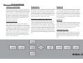
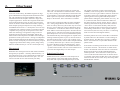
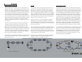
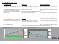
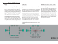
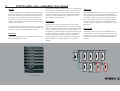
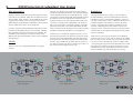
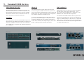
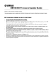
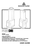
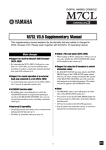
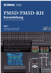
YAMAHA System Solutions white paper
Networked audio system design with ES100™
This white paper’s subject is Networked audio system design with ES100™.
The design concepts in this paper support systems varying from small touring
event setups to medium scale integrated live installations. That does not mean
that these design concepts are the best solution to all system specifications, other
network topologies and audio protocols should always be considered in the initial
phase of the design project. The advantage of these Yamaha System Solutions
design concepts is that they are based on Ethernet / ES100™, both open protocols
that use computer networking components widely available on the market. Other
compatible brands of both network and audio equipment can be included in the
design concepts, assuring maximum flexibility and project efficiency for system integrators. It is also good to know that the design concepts are not just a theoretical
exercise; we have built, tested and installed many systems based on these design
concepts so you can be confident that they will work in real life.
We assume the reader is a system integrator with detailed knowledge of analogue
and digital audio, and basic knowledge of networking technologies as covered in
the ‘Yamaha System Solutions - an introduction to networked audio’ white paper.
The Yamaha Commercial Audio team.
ES100™ networked audio systems
1.
System design
2.
EtherSound
3.
ES100
4.
ES100 audio routing
5.
Redundancy issues
6.
Connectivity issues
7.
ES100 audio only redundant ring design
8.
ES100 integrated redundant ring design
9.
Yamaha ES100 devices
10.
Programming ES100 devices
11.
Documentation
12.
Troubleshooting
13.
Example 1: 48ch FOH - MON - stagerack
14.
Example 2: 32ch FOH - MON - dual stagerack - amprack
The complete package
1.
System design
Customer’s requirements
Design options
Design tools
The first step in any design is to chart the customer’s requirements. Sometimes the requirements can be found in
a formal tender if a consultant has already been involved
in the customer’s system specification process. In many
cases the consultant or system integrator has to discuss
the customer’s requirements in depth to find the most
appropriate system specifications, and perhaps suggest
additional system possibilities made possible by new
technologies on the market.
Based on the system specifications document basic design
options can be conceived. The main decision to make is
the selection of the technology to be used: analogue or
digital, point to point or networked, closed (proprietary)
or open (manufacturer-independent) platforms etc. These
decisions are fundamental as they determine the degree
of freedom allowed in further design stages.
The more complex a system the more important design
tools become. A small system can be described in words
or an excel sheet, but larger or more complex systems
have to be described in drawings to be able to communicate them to all stakeholders in a project. In modern times
software programs are used to construct system designs
such as AutoCAD in the contracting business, StarDraw
in the audio markets.
Selection of network and audio devices
System test
After the technology platforms have been selected the
system’s actual network and audio devices must be
selected. Input parameters for selection include feature
The second step is to draw up a system specification
based on the customer’s requirements. A system specifi- set, audio quality, technical reliability, supplier reliability
and of course cost level. There are few products with an
cation document contains the requirements for a system
to fullfill as operational parameters. The system specifica- ‘A-score’ on all of these parameters; quality comes with
tions should not include any direction to actual solutions higher costs, reliability as well. The designer must study
each system component’s feature set in depth to assess
as that would narrow the scope of possibilities in the
if it meets the system specifications or not, and conceive
design stage. Only by keeping the system specifications
creative solutions in case no matching products are availand the design solution options strictly separated can
able.
the broad scope of choices be truly considered by the
designer, allowing for maximum flexibility, quality and
creativity in the design stage.
System specifications
A very important part of the network design process is to
conduct (sub) system tests. Especially network systems
using managed switches offer an extremely high functionality level that require system tests to verify that all
parameters have been programmed correctly.
Training & after sales
A networked audio system offers different functionality
compared to analogue systems. Therefore the design of
appropriate after sales and training activities for future
users of the system is an important part of the design
stage.
2.
EtherSound
The beginning
At the turn of the century, three R&D engineers at Digigram studied Ethernet compliant audio distrbiution methods, with CobraNet as the world standard at that time.
CobraNet has been developed to function in large scale,
complex applications - but the three engineers didn’t have
such a broad application scope in mind - they narrowed
it down to the live sound reinforcement market, requiring
much simpler topologies and protocols. They ended up
with EtherSound version 1.0 - developed to serve one-way
connections from a mixing console to a speaker controller
/ amplifier setup using only an inexpensive CAT5 cable.
Their new technology was applied in a large scale live
application for the first time in September 2003 by the
sound reinforcement department of Radio France during a
performance of the opera Carmen - driving 16 loudspeaker
stacks located throughout the 80.000 seat arena ‘Stade de
France’ in Paris. Everybody involved was taken by surprise
- Digigram provided a full working system, doing exactly
what was needed for this job - but in a much simpler way.
The protocol
Remember how the engineers from Peak Audio solved the
timing and sync problem - caused by Ethernet latency - in
the Cobranet protocol ? One CobraNet device sends out a
beat packet on a moment the network is quiet - so it can
travel to all other devices with extremely low delay.
Carmen at the Stade de France, Paris
Then - after receiving the beat packet at virtually the
same time - all audio devices send their audio - with every device waiting for a fixed amount of time before the
received audio is output. This method provides the time
buffer required to cope with store/forward and queue
delays in the network. That’s CobraNet in a nutshell.
The inventors at Digigram made one genius simplification - stating simply that the network must be a daisy
chain. In a daisy chain every device has only one source
device to receive data from, and one destination device
to send data to - so the device doesn’t have to study the
MAC address in the Ethernet packet to decide where the
packet must go. This also means that store/forward and
queue delays never ever occur in an EtherSound system.
The EtherSound chips from Digigram are capable of forwarding an Ethernet packet in just 1,4 microseconds. In
the audio world we start to worry only if a delay grows
above 11 microseconds ( which is half a sample at 48kHz
), so a daisy chain with up to 7 devices is no problem at
all. And as the delay can be calculated exactly - knowing the 1,4 microsecond delay of an EtherSound device
- systems with more than 7 devices can be tuned to be in
sync with short digital delays of a few samples.
EtherSound Version 1
EtherSound version 1 packs the 24-bit samples of 64
audio channels in one packet and sends it down the
daisychain with a pace of 48.000 packets per second.
EtherSound 1.0: downstream daisy chain.
The number of packets is equal to the sampling rate
of 48kHz, so the receiving device can use the packet
stream as a source to get a stable wordclock. All devices
in the daisy chain receive packet after packet, quickly
replacing and/or inserting individual samples in the
packets before sending the packet further on its way - all
in 1,4 microseconds. A device that inserts audio into
the packet stream is called a ‘master’ device, a device
extracting channels from the packet stream is called a
‘slave’ device. At the end of the daisy chain, the last
device, the audio packets are sent to the last connector
with nothing connected to it - these packets end up in
silicon heaven (don’t feel sorry for them - it’s like being
stuck in an elevator with Brigitte Nielsen).
Inside the packets also some control data is transmitted
by the first device in the network to control settings of
all other devices. This first device is always a ‘Master’
device - the first device to input audio channels in the
packet stream.
So all audio is streaming from the devices IN connector
to the OUT connector - this direction is called ‘Downstream’. The Ethernet connection also has a connection
flowing from the last to the first EtherSound device
called ‘Upstream’. This connection is used by the devices to send status information back to the first device.
A computer connected to the first device can control and
monitor all other devices in the daisy chain using EtherSound Monitor software.
3.
ES100
EtherSound version up
ES100
Integrating ES100
After the first EtherSound licenses were distributed and
products were built - e.g. by Digigram, Fostex/Netcira and
Auvitran - the Digigram engineers decided to fill up the upstream connection with audio as well - so audio can travel
not only from the first device to the last, but also from the
last to the first. With EtherSound version 1.X and higher
this was possible - but only with hardware that supported
this bi-directional mode. In this mode, the last device in the
daisy chain loops back the packet stream, offering a system
capable of connecting 64 channels downstream and 64
channels upstream at the same time - adding up to a total of
128 channels.
Using a daisy chain topology, EtherSound offers a very
simple set-up, low latency and high channel capacity.
But there is a downside... daisy chains are dangerous.
If one cable or device breaks the network is cut in two
parts. Using Ethernet trunking protocols in a managed
switch, or dedicated units such as the Auvitran AV-RED,
designated cables in a daisy chain can be protected, but
the overall system can not recover from the majority of
failure sources in the network. Unless....
An ES100 device sends audio as standard Ethernet packets multicast for downstream, unicast for upstream. This allows
the ES100 packet streams to be tunnelled through a network
using VLANs. In a star topology network this would result
in a non-redundant system, but when ES100 is tunnelled
through a ring topology then the system stays redundant,
and offers the possibility to tunnel other VLAN’s alongside
the ES100 audio stream such as IP video, control data for
speaker controllers, Studiomanager, DME designer, DMX
light control. If a gigabit backbone ring is secured with the
Spanning Tree Protocol, the recovery timing of ES100 is
slowed down to the STP recovery timing. By allowing only
ES100 to be a ring topology, and the rest of the network a
daisy chain without any redundancy, the ES100 recovery
stays virtually seamless when emergency clock is enabled.
For this to work, the last device must be programmed to
loopback the audio from downstream to upstream. The
upstream data will end up back in the first device in the
daisy chain - where it ends up in silicon heaven - which
means that it is not output to its IN connector as that would
overload the NIC of the computer attached to control and
monitor the system. To support the bi-directional mode the
vocabulary of EtherSound was expanded with ‘loopback
device’ and ‘Primary Master’ respectively.
Later updates of the EtherSound protocol included ‘start of
loop’ and ‘end of loop’ settings - allowing multiple loops in
a daisy chain to exist.
ES100 is the latest version of EtherSound - adding a
redundancy protocol similar to Ethernet’s Spanning
Tree. With this protocol the daisy chain can be closed to
become a redundant ring, capable of recovering from any
failure in the network.
For this the EtherSound vocabulary is expanded with a
name for the device managing the backup link in the ring
- the ‘Preferred Primary Master’. To allow the redundancy to recover from all connections in the network, a
special way of order-independent routing has to be used
- more about this in a later chapter.
To connect daisy-chained branches to an ES100 ring, a hardware router must be used such as the Auvitran AVM500-ES.
Break-outs from the ring can also be made using a special
ES100SPKR version device such as the Barix Extreamer.
The ES100SPKR version only receives the downstream
audio, but doesn’t send any upstream information - so the
ring’s audio timing is not disturbed.
Failure recovery of ES100 rings with emergency clock
enabled on all devices is virtually seamless. Without
emergency clock it’s less than 3 seconds.
switch
switch
switch
switch
switch
switch
switch
bi-directional daisy chain
redundant ring
switch
integrated redundant ring
4.
ES100 audio routing
ES100 routing
Left clicking sends a downstream ES100 channel to the
This way the routing stays valid whatever the order of the
device’s physical output, right-clicking sends the upstream devices in the daisy chain. (see figures 3 and 4) . This limits
ES100 channel to the input.
the total channel count to 64.
An ES100 packet stream consists of 48.000 packets per
second, with each packet carrying 64 samples. This arrangement uses an Ethernet bandwidth of appr. 85Mb.
A device in an ES100 ring supports two packet streams
named ‘downstream’ and ‘upstream’. The downstream
packets are broadcast packets, received from the RX pair
of the 100Mb IN connector and sent to the TX pair of the
100Mb OUT connector. The upstream packets are unicast
packets, received from the downstream device connected
to the RX pair of the OUT connector, sent to the device’s
MAC address. After inserting/extracting channels these
packets are sent to the MAC address of the upstream device connected to the TX pair of the 100Mb IN connector.
Although the explanation above sounds very complex, it
is very easy to use. A device can input channels from the
outside world into a downstream or an upstream packet
stream, selecting one of the 64 channels in the packet.
In the ES monitor software this is visualised as a routing
grid with the physical inputs on the vertical scale and the
ES100 channels on the horizontal scale. Left-clicking a
grid cell sends the physical input to the downstream channel, right-clicking sends it to the upstream channel. Output
devices use the same visualisation.
audio insert
A
Order independent routing
ES100 ring settings
Being able to send channels both downstream and upstream means that each device can send channels to 128
destinations - 64 channels downstream and 64 channels
upstream. But this has a catch - routing channels this way
assumes a fixed order of the devices in the ring. Picture an
ES100 daisy chain with a device sending audio to a device
upstream using the upstream packet stream. The receiving
device then picks up the channels from the upstream packet stream and outputs it to the analogue world (see figure
1). Then, for some reason the receiving device is moved to
a position downstream. Now the upstream - which doesn’t
loop back but ends in silicon heaven - can no longer reach
the receiving device (see figure 2).
One of the main features of the ES100 protocol is the redundant ring topology, assigning one device as the ‘Preferred
Primary Master’ (PPM). The PPM will then block its input
and unblock it as soon as the ring is broken.
This means that 128 channel routing is order dependent
- as soon as the order of devices is changes the routing is
incorrect. For systems with varying components - such as
used by touring companies - this can be a problem.
The solution is order independent routing. This can be
simply achieved by inserting channels downstream only,
and extracting upstream only.
audio insert
B
C
D
audio extract
figure 1: bi-directional routing
insert downstream
extract downstream
B
C
A
audio extract
(empty channel)
figure 2: change of order
... no output at C
In redundant state the ring functions as a daisy chain, with
the downstream audio starting at the PPM, and the device
upstream relative to the PPM as loopback device. As soon
as the ring is damaged the PPM will unblock its input, and
the Primary Master function will be taken over by the device
downstream of the disconnection. So, a new daisy chain
is formed, with a different Primary Master and loopback
device compared to the redundant state - changing the order
of the devices in the resulting functional daisy chain.
For a redundant ring system to be able to recover not only
the connections but also the audio routing, the order-independent routing method must be used. In fact, as soon as the
ring mode in an ES100 system is enabled (by appointing the
PPM), the ES Monitor software’s routing page allows only
inserts on downstream channels and extractions on upstream
channels - the software will not accept any other routing.
audio insert
D
A
audio insert
B
C
D
audio extract
figure 3: order independent routing
insert downstream
extract upstream
B
C
A
audio extract
figure 4: change of order
D
5.
Redundancy issues
Redundancy rating
Safety rating
Redundancy monitoring
A networked audio system combines network devices
with audio devices. Compared to analogue audio systems the network is the unknown factor - with serious
effect on a system’s performance in case of an emergency such as a cable break or device power down. To
cope with this, networks normally have redundancy
built in so the system can recover automatically from
emergency events.
While the redundancy rating indicates the ability of a network to recover from an emergency event, the probability
that such an event occurs is determined by the number of
failure sources in the network - the more cables and NIC’s
the higher the probability of a failure.
Having a redundant network is one thing, knowing that
a network is redundant is another. Fact is that without
special monitoring systems, a user can not see if a system
is redundant or not. Without such a system it is possible
for a user to think a network is redundant while in reality
it is not.
The safety rating is defined as the redundancy rating divided
by the number of failure sources in the network.
In most cases it is not convenient to utilise monitoring
software such as HP-Openview or 3COM network moniFrom all possible audio network configurations, the ES100
tor. For most applications a simple monitoring system can
audio only redundant ring configuration has the least failure be built in utilising packet sensing or audio.
sources. As a result, it has the highest safety rating for small
and medium scale configurations - even higher compared to In case of packet sensing a logical sense pulse is transdouble star and double ring.
mitted into the network, forced through all cables and
switches using multiple VLANs. The returning signal can
be monitored to asses if the network is redundant or not.
Redundancy
The weighted sum of probabilities of a system to
recover from random failures in the system is called
the redundancy rating. This rating indicates a network’s
ability to recover from one or more failures in a row.
Different topologies and redundancy protocols lead to
different redundancy ratings.
For all redundant single ring topologies the redundancy
rating is always 100% - the network can recover from
any single failure.
The Ethernet redundancy protocols such as the Spanning Tree Protocol and Trunking offer protection against
full scale disasters such as cable breaks and device power
downs. These protocols can not protect a system from
intermittent failures such as loose connectors. To deal with
intermittent failure sources in a system it is necessary to
implement high standards for design and component quality.
In comparison, a double star or double ring network
have higher redundancy ratings, a trunked daisy chain
has a lower redundancy rating.
In case of an audio only ES100 ring, an audio signal can
be sent by the PPM using an unused ES100 channel.
Then the downstream audio signal can be picked up by
an ES100 device before it returns to the PPM input. As
this signal is tapped from downstream - order dependent
routing - it will be disconnected in case of an emergency,
while the rest of the audio will recover.
safety rating result for networks with 2 to 20 locations
redundancy rating result for networks with 2 to 20 locations
safety rating (normalised to audio only ES100 for 2 locations)
Redundancy rating (normalised to ring redundancy)
100%
600%
90%
500%
80%
70%
audio only ES daisy chain
400%
audio only ES daisy chain
int ES daisy chain
int ES daisy chain
Cn single star
60%
Cn single star
ES trunked daisy chain
ES trunked daisy chain
300%
CN trunked daisy chain/star
CN trunked daisy chain/star
50%
ES100 audio only ring
ES100 int ring
ring
CN double star
CN int ring
40%
CN double star
CN double ring
CN double ring
ES100 int ring trunk
200%
CN int ring trunk
ES100 int ring trunk
30%
CN int ring trunk
20%
100%
10%
0%
0%
2
3
4
5
6
7
8
9
10
11
12
13
14
15
16
17
18
19
20
number of locations
2
3
4
5
6
7
8
9
10
11
12
13
14
15
16
17
18
19
20
number of locations
6.
Connectivity issues
Cables
Connectors
Multiple access points & large systems
ES100 systems use CAT5E cabling or higher. Connected straight from an OUT port to an IN port - under ideal
conditions - the cable can be up to 100 meters long.
For direct connection most ES100 devices have touring
grade Ethercon connectors. With patch fields also EtherCon
connectors and cables can be used.
However in real life conditions are never ideal. Also
when ES100 devices are used in a touring environment
the RJ45 connectors will wear out at some moment in
time. To prevent this from happening in the middle of a
large scale pop concert it is good practise to use a patch
field - e.g. with EtherCon connectors - and replace the
cables and connectors in a managed time interval.
A connection can be converted to multimode or singlemode
fiber using a media converter. In the audio markets Neutrik
OpticalCon and Connex Fiberfox are the most commonly
used connectivity systems.
ES100 is designed for use in small and medium scale
redundant ring topology live systems. In a fixed
installed system with many access points - such as
live systems for theatre, cultural venues and concert
halls - the ring topology is not suited as unused access points have to be passively connected resulting
in ring segments with many passive connections. This
results in a much higher amount of failure sources
(every cable and connector is one), but also in deteriation of the Ethernet signal quality caused by the
many mechanical connectors in ring segments. For
multiple access point systems and for fixed installed
systems with more than 5 active locations and/or 64
channels a double star topology using Cobranet can
be considered as an alternative.
In real life applications cables will be used-ones,
connected through Ethercon patch panels, with dimmerpacks and high power ampracks nearby. In these
cases we advice to restrict copper cable lengths to cover
on-stage distances only, and move to fiber connections
for longer distances such as the FOH-stagerack connections.
Frequent inspection of the connector and cable quality is
recommended - replacing them in a managed time interval
to prevent intermittent problems in the network’s connectors
from which the redundancy protocols can not recover.
With analogue audio cabling a system of male and female connectors is adopted - male for output and female
for input. Ethernet is bi-directional, so the arrangement is
different: male for cables, female for chassis connectors.
Hence, labelling cable connectors and chassis connectors is
very important, as is the training of the users of the system
to use the labelled information when connecting the system
locations.
B
A
ring topology with 12 access points.
A -> B passes 5 passive links.
A
B
star topology with 12 access points.
A -> B passes only active links.
7.
ES100 audio only redundant ring design
No IT !
An ES100 audio only system supports 64 audio channels
and a serial connection for the head amp control. No further IP over Ethernet services can be integrated. The big
advantage of such a system is that the system does not
include any IT components. The network is built with a
number of ES100 devices and the same amount of cables.
Nothing else is required.
The ES100 devices in such a system can be connected in
any order, as long as OUT connectors are connected to IN
connectors - just as with analogue audio cabling.
Locations
For the user an ES100 audio only system includes locations and long distance cables.
Take-over
A location can contain one ES100 device, or several ES100
devices daisy-chained with patch cables. It is good practise
to mechanically secure the patch cables in the i/o rack to
prevent intermittent connectivity problems in them. Patch
cables are not removed after every application, so they
don’t need to be time-managed.
The ES100 redundancy protocol is very fast - the redundant ring recovers form a failure almost immediately.
The synchronisation of the ES100 devices then take 2 to
3 seconds to resync before restoring the audio connections. When all devices in the ring support the ES100’s
‘emergency clock’ feature the re-synchronising is also
virtually seamless, resulting in an immediate recovery of
the system.
Wordclock
The ES100 ring has to support any device to be the Primary Master. As the Primary Master is also the wordclock
source, an ES100 system can not sync to the outside world
as this would fix the position of the wordclock device - if
an emergency occurs and the Primary Master changes then
the device synced to the outside world will no longer be
syced to the ES100 ring. This is specially a problem in
broadcast applications, and in applications requiring more
than 64 channels - as multiple rings can not be synced
together.
HA control
The ES100 protocol includes a low bandwidth serial
tunnel capable of supporting an RS422 connection. This
connection can be used to provide head amp control on
Yamaha mixing consoles with DME and AD8HR mic
pre-amps.
A/D convertor
AES/EBU hub bridge
ES100 IN
ES100 OUT
A/D convertor
AES/EBU out A
USB
RS-422 HA Remote
I/P 1
AES/EBU out A
AES/EBU out B
AES/EBU out B
RS422 HA remote
RS422 HA remote
I/P 1
I/P 1
RS422 / PC
RS422 / PC
RS422 / PC
I/P 2
I/P 2
I/P 2
I/P 2
AES/EBU B
I/P 3
I/P 3
I/P 3
I/P 3
AES/EBU C
I/P 4
I/P 4
I/P 4
I/P 4
AES/EBU D
I/P 5
I/P 5
I/P 5
I/P 5
AES/EBU E
I/P 6
AES/EBU F
I/P 7
I/P 6
I/P 6
I/P 7
I/P 8
I/P 6
I/P 7
I/P 8
I/P 7
I/P 8
I/P 8
Word Clock Out
Word Clock In
MIDI In
A/D convertor
AES/EBU out A
AES/EBU out B
RS422 HA remote
I/P 1
RS422 / PC
Word Clock In
A/D convertor
AES/EBU out A
AES/EBU out B
RS422 HA remote
COM
AES/EBU A
Word Clock Out
Word Clock In
Word Clock Out
Word Clock In
Word Clock Out
Word Clock In
Word Clock Out
MIDI Out
MAINS I/P
YAMAHA NAI48-ES
MAINS I/P
MAINS I/P
YAMAHA AD8HR
MAINS I/P
YAMAHA AD8HR
A/D convertor
MAINS I/P
YAMAHA AD8HR
A/D convertor
AES/EBU out A
YAMAHA AD8HR
D/A convertor
D/A convertor
AES/EBU out A
AES/EBU out B
AES/EBU out B
1-8 in
1-8 out
RS422 HA remote
1-8 in
O/P 1
MY8AE
1-8 out
O/P 1
MY8AE
RS422 HA remote
O/P 2
O/P 2
I/P 2
I/P 2
O/P 3
O/P 3
I/P 3
I/P 3
O/P 4
O/P 4
I/P 4
I/P 4
O/P 5
O/P 5
I/P 5
I/P 5
O/P 6
O/P 6
I/P 1
I/P 1
RS422 / PC
RS422 / PC
I/P 6
I/P 6
O/P 7
I/P 7
I/P 7
O/P 8
I/P 8
I/P 8
Word Clock In
Word Clock Out
Word Clock In
Word Clock Out
Word Clock In
O/P 7
O/P 8
Word Clock In
Word Clock Thru
location back side
MAINS I/P
YAMAHA AD8HR
MAINS I/P
YAMAHA AD8HR
Com
MAINS I/P
MAINS I/P
YAMAHA DA824
location functional diagram
location components
Word Clock Thru
Com
YAMAHA DA824
8.
ES100 integrated redundant ring design
Why integration ?
Sharing an ES100 application with other Ethernet connections can be very efficient. Many IP over Ethernet services
such as DMX, video, VoIP etc. can be added to the system
using the same cabling. Also control protocols such as
DME designer, Studiomanager and Media control systems
such as AMX and Crestron can be integrated.
For more complex systems additional ES100 daisy chain
branches and ES100spkr devices can be added - although
these segments of the network will not be redundant. For
redundant ‘hybrid’ designs, Cobranet branches can be
added to the ring with a hardware router such as a DME or
mixing console.
VLANs
There are two ways of integrating ES100 in a gigabit
network.
ESD
switch
switch
One way is to design a VLAN structure that connects
the ES100 segments individually, only taking bandwidth
on the segments between the connected devices - in the
picture below VLANs ESA, ESB, ESC and ESD connect
all segments of the ring. This allows inexpensive lowcapacity switches to be used. The downside is that such
a system is no longer order-independent - the locations
have to be connected in a predetermined way. Although
physically the system is now order-dependent, the functional connection of the ES100 devices is still order-independent so the ES100 redundancy is still supported.
Another way is to design the segment VLANs to cover
all locations. This allows the physical connections of the
locations to be order independent. The downside is that
all locations will contain all segments’ broadcast packet
streams - appr. 85Mb load per packet stream, in the picture below 4 streams per cable / 8 streams per switch - so
the switches must be high capacity ones.
ESC
ESB
ESA
ESD
ESA
switch
switch
switch
switch
switch
switch
switch
ESC
switch
switch
switch
An integrated ES100 ring topology system combines
ES100 redundancy protocol with the Ethernet network
redundancy protocol. The ES100 redundancy protocol is
very fast - if emergency clock is enabled on all devices it’s
virtually seamless. Unfortunately as soon as the Ethernet ring - supporting the ES100 ring through a VLAN
structure - Spanning Tree Protocol starts to react to an
emergency event, it may block all ports in the network for
a short while, preventing the ES100 protocol from switching-over seamlessly.
Again, there are two ways of using the two redundancy
protocols. One way is to use both, in which case the audio
take-over time is slow, at least several seconds. An alternative way is to leave the Ethernet system as a daisy chain
- only closing the ring between two ES100 devices. In this
case STP is not required - the physical network is a nonredundant daisy chain. The ES100 connections however
form a redundant ring, with quick take-over timing.
ESD
switch
switch
switch
switch
switch
switch
ESA
switch
ESC
ES100 integrated system
- order independent
switch
switch
switch
ESB
ES100 integrated system
- order dependent
Redundancy
switch
switch
ES100 ring on an integrated
daisy chain
ESB
9.
Yamaha ES100 devices.
MY16-ES64 & MY16-EX
SB168-ES
DME satellite-ES
The MY16-ES64 offers a 64 channel connection to an
ES100 network. However, the card can only route 16 of
these channels to the host device (a console or a DME).
The other 48 channels can be connected to the host by
daisy chaining up to three MY16-EX cards.
The SB168-ES offers 16 high quality mic/line inputs
and 8 line outputs at 48kHz. The mic/line inputs can be
remote controlled by Yamaha digital mixing consoles and
DME engines. The inputs and outputs can be assigned to
any of the 64 channels in an ES100 system.
DME satellite come in 3 flavours: 8 remote controllable
mic/line inputs, 8 line outputs and 4 inputs + 4 outputs. All have the same DSP power - about 80% of the
DME24N , but without the SPX components.
A system of three SB168-ES units offer 48 mic/line inputs in total, and 24 line outputs - a channel count of 72.
An ES100 redundant ring only supports 64 channels, so
The NAI48-ES is a bi-directional AES/EBU bridge to an in this case 8 channels, for example outputs, can be used
ES100 network. At 48kHz the NAI48-ES can interface 48 double - feeding from the same ES100 channel.
channels, at 96KHZ 32 channels. There are 6 AES/EBU
25-pin subD ports, compatible with AD8HR and MY8AE
pin configuration.
NAI48-ES
SB168-ES
The ES100 side of DME satellites offer 16 inputs and 16
outputs to the ES100 network, which is more than the analogue i/o. DME satellites are ideal for use in ‘distributed
DSP’ systems - where DSP power is not concentrated in
one device but in several devices, linked together with the
low latency ES100 protocol.
NAI48-ES
MY16-ES64
DME Satellite-ES
MY16-EX
10.
Programming ES100 devices
Set and forget.
What to set
Because the ES100 protocol includes the audio timing it
does not allow any other Ethernet traffic on the ring as
that would cause waiting queues and disturb synchronisation. Hence, it is not possible to connect a computer to
a closed ES100 ring for programming and monitoring
unless a 3rd party device is used featuring a ‘3rd port’.
First set the system to ring mode by enabling one device
as PPM. The system now automatically goes into ring
mode, and the PPM will display an icon to indicate that
the ring is broken.
HA control
The Yamaha Head Amp (HA) control protocol can be
used to control the head amp of an external input unit
by a mixer or DME device. It uses an RS422 connection, which can be tunnelled through an ES100 network
directly by a Yamaha device such as the DME satellite
Next, enable the emergency clock on all devices
and LS9, or through the RS422 connection of the MY16ES64 in hosts such as the PM5D, M7CL, DM2000,
In practise, the applications best suited to be designed
Next, program the routing for each device. As the devices DME24N and DME64N.
with ES100 are ‘set and forget’ applications. This means
are in ring mode the software accepts only order-indethat the routing is programmed once, and then stored in
pendent settings: inputs to downstream, outputs from
HA control can be a single connection between a mixer
the system’s devices to provide the specified functionality upstream.
and an i/o rack, but also a series of connections to mulevery time the system is connected and powered on.
tiple i/o racks - for each ES100 device the HA IDs to be
Next, set HA control mode for each device: baudrate,
controlled can be programmed individually.
During the programming redundancy is not needed, so
unicast targets and enable the serial tunnel.
is can be done by breaking the ring in a random location
and connecting a PC to the IN port of the device at hand. Last, but not least, store the settings in non-volatile
The ES Monitor software then can control all devices in
memory for each individual device. This way the system
the ring. After programming and storing the settings in all will power-up with the correct settings every time.
devices simply remove the PC, close the ring again and
start testing.
enable PPM
HA control MY16-ES64
(in PM5D)
HA control NAI48-ES
store in non-volatile memory
11.
Documentation
The importance of documentation
The layer 1 diagram
The VIMP list
Troubleshooting analogue systems is an art of its own,
but relatively easy compared to troubleshooting a network - in an analogue system every connection is visible
as a cable. In a networked system the functional connections are completely separate from the physical - visible
- cabling. Without proper documentation about how the
connections are programmed it is extremely difficult to
troubleshoot a system. The time it takes to find the cause
of a problem in a system can be shortened by magnitudes
if proper documentation is included on-site. We advise
to make the system documentation available on paper,
packed with the system. Electronic form should be pdf
so anyone can read it without having to install dedicated
software.
The network hierarchy is divided in seven layers according to the OSI model. Layer 7 represents the user
interface with humans, for example on a computer
display. Layer 1 represents the electronics in the system’s
hardware.
Devices in a network are identified with their MAC and
IP addresses. Software such as IP scanners, ES monitor and Cobranet Discovery is often used to monitor the
network in order to analyse it and find out what is wrong.
To connect the system’s hardware with the MAC and IP
addresses they must be charted in the system’s documenIT people generally live in layers 2 to 7. Audio people are tation - or, if this is not done, MAC addresses have to be
used to living in layer 1: connectors and cables. In both
identified one-by-one visually - a rather time consuming
cases the starting point of any networked audio system’s activity.
documentation is the layer 1 diagram - which both IT
people and audio people can understand - although IT
In addition to the MAC and IP addresses, the system’s
people sometimes deny that layer 1 even exists.
switches’ VLAN port assignments and the audio protocol
settings must be clearly charted.
The layer 1 diagram includes all network hardware, all
audio hardware and the main connections. For large
All together this information summarises as the VIMP
The documentation should at least include the layer 1 dia- systems often two separate diagrams are included, one for list: VLAN port assignment + IP table + MAC table +
gram and the VIMP list, and should be updated with all
the network - showing only network hardware and conProtocol settings.
changes and upgrades applied to the system. Additional
nections - and one for audio - showing both network and
information to include is firmware and software versions, audio hardware and connections.
a system user manual and maintenance protocol.
2 * Etherc on panel
EtherCon
UTP
EtherCon
UTP
Input rack TS1
Neutrik Ethercon
8 + 2 switch
AES/EBU hub bridge
Gigabit SFP 25
TX 1
CobraNet P rimary
Gigabit TX
TX 2
CobraNet S ecundary
A/D convertor
USB
A/D convertor
AES/EBU out A
RS-422 HA Remote
AES/EBU out B
input panel
TX 3
COM
AES/EBU hub bridge
AES/EBU out A
ES100 IN
AES/EBU out B
ES100 OUT
RS422 HA remote
XXX
I/P 1
COM
I/P 1
RS422 / P C
TX 4
Prim
192.168.0.31
Sec
192.168.0.23
Prim
192.168.0.25
Sec
192.168.0.30
USB
RS-422 HA Remote
input panel
RS422 HA remote
XXX
RS422 / P C
AES/EBU A
I/P 2
I/P 2
AES/EBU A
AES/EBU B
I/P 3
I/P 3
AES/EBU B
AES/EBU C
I/P 4
I/P 4
AES/EBU C
TX 5
RS-232C
1
CN
2
1
CN
2
2
CN
2
2
CN
2
3
DEF
1
3
DEF
1
4
DEF
1
4
DEF
1
5
DEF
1
5
DEF
1
6
ES A
9
6
ES A
9
7
Local
8
7
Local
8
8
Rec 1
4
8
Rec 2
5
9
U/L
10
U/L
9
U/L
10
U/L
3
DEF
1
3
DEF
1
4
DEF
1
4
DEF
1
5
DEF
1
5
DEF
1
6
ES A
9
6
ES A
9
7
RED
3
7
RED
3
8
Rec 1
4
8
Rec 4
7
9
U/L
10
U/L
9
U/L
10
U/L
3
DEF
1
3
DEF
1
4
DEF
1
4
DEF
1
5
DEF
1
5
DEF
1
6
ES A
9
6
ES A
9
7
Local
8
7
Local
8
8
Rec 2
5
8
Rec 3
6
9
U/L
10
U/L
9
U/L
10
U/L
4
DEF
1
4
DEF
1
5
DEF
1
5
DEF
1
6
ES A
9
6
ES A
9
7
Local
8
7
Local
8
8
Rec 3
6
8
Rec 4
7
9
U/L
10
U/L
9
U/L
10
U/L
TX 6
OpticalCon connector
OC A
LC A
OC B
LC B
AES/EBU D
MAINS I/P
I/P 5
I/P 5
AES/EBU D
TX 8
D-link
I/P 6
DES-3010G
Neutrik NO2-4FDW
Mix rack TS2
TX 7
8 + 2 switch
Gigabit SFP 25
TX 1
Gigabit TX
TX 2
I/P 6
I/P 7
Word Clock Out
AES/EBU D
I/P 8
Neutrik
Word Clock In
Neutrik
Word Clock In
MIDI In
AES/EBU C
I/P 7
I/P 8
Word Clock In
Word Clock Out
Word Clock In
Word Clock Out
Word Clock Out
MIDI Out
MIDI In
1
CN
2
1
CN
2
2
CN
2
2
CN
2
MIDI Out
TX 3
Amprack TS3
TX 4
TX 5
RS-232C
Prim
192.168.0.26
Sec
192.168.0.24
TX 6
MAINS I/P
TX 7
MAINS I/P
MAINS I/P
MAINS I/P
MAINS I/P
YAMAHA NHB32-C
YAMAHA AD8HR
YAMAHA AD8HR
Digital Mixing Engine
A/D convertor
A/D convertor
TX 8
YAMAHA NAI48-ES
D-link
DES-3010G
AES/EBU out A
CobraNet P rimary
serial server
CobraNet S ecundary
RS-422 HA Remote
RS-422
AES/EBU out A
AES/EBU out B
output panel
Network
Network
input panel
Amprack TS4
RS422 HA remote
XXX
O/P 1
I/P 1
O/P 2
I/P 2
I/P 2
O/P 3
I/P 3
I/P 3
O/P 4
I/P 4
I/P 4
O/P 5
I/P 5
I/P 1
I/P 5
RS422 / P C
RS422 / P C
Prim
192.168.0.27
Sec
192.168.0.22
rack
TS2
TS2
TS1
TS4
TS4
TS3
TS3
device
DME24N
DME4io-ES
DME4io-C
DME8o-C
DME8i-C
DME80-C
DME80-ES
12V DC
B&B ESP901
O/P 6
I/P 6
I/P 6
O/P 7
I/P 7
I/P 7
O/P 8
I/P 8
I/P 8
Neutrik
GPI in 1
GPI out 1
GPI in 2
GPI out 2
GPI in 3
GPI out 3
GPI in 4
GPI out 4
Neutrik
Neutrik
Word Clock In
Word Clock Out
Word Clock In
Word Clock Out
GPI in 5
GPI in 6
GPI in 7
GPI in8
MAINS I/P
MAINS I/P
YAMAHA DME8o-C
YAMAHA AD8HR
layer 1 diagram
2
CN
2
2
CN
2
AES/EBU out B
input panel
RS422 HA remote
XXX
1
CN
2
1
CN
2
MAINS I/P
YAMAHA AD8HR
1
CN
2
1
CN
2
2
CN
2
2
CN
2
3
DEF
1
3
DEF
1
IP
60
61
62
63
64
65
66
MAC
36
7d
b3
0e
83
15
7a
GROUP
7
5
3
1
4
1
2
notes
for MIDI only, defective
should be DME8o-C
should be DME8o-ES
VIMP list
VLAN
1
2
3
4
5
6
7
8
9
Default
CobraNet
RED
Rec 1
Rec 2
Rec 3
Rec 4
Local
ES A
12.
Troubleshooting
1. Find information.
2. Ping the default VLAN.
Step number one: find the system’s documentation. Without the documentation it takes up to 10 times longer to
troubleshoot. The information should normally come as a
paper copy, or as pdf on a CD, USB stick or website.
If the system contains switches then the second step is
to ping the default VLAN with an IP scanner, and compare the live IPs with the documentation - assuming that
the default VLAN is used for network management and
control. If one IP is missing then that’s where to look
for a problem.
If there is no information available then the starting point
is an inspection of the system - sketching the layer 1 diagram, charting the MAC and IP addresses where possible.
If the system includes managed switches then the VLAN
structure must be charted as well - without it there’s no
way to tell what is connected to what. Often this means
calling many people to find the telephone number of the
network programmer.
‘Angry IP scanner’
ES Monitor will show all ES100 devices in the ring - if
one is missing then that’s where to look for a problem.
If all devices are alive then check the connection monitor
at the bottom of the ‘properties’ tab. The monitor must be
enabled in the ES Monitor preferences. The connection
monitor graph shows the network stability history of the
downstream and upstream connections. If any dip shows
up that’s where to look for a problem.
If the network doesn’t contain switches then skip step 2.
4) Check the top 3 of problem causes.
3. Launch ES Monitor.
Disconnect a cable from any ES100 device’s OUT port
and connect it to a computer, then launch ES Monitor.
1) wordclock settings in MY card hosts.
2) loose patch cables
3) faulty long distance cables / connectors
ES Monitor
connection monitor
13.
Example 1: 48ch FOH - MON - stagerack
Mixing consoles.
Stagerack.
Network.
The system includes two PM5Ds for FOH and MON
locations. Both consoles have one MY16-ES64 card and
two MY16-EX cards for a total of 48 channels from the
stagerack. The 16 channels left in the 64 channel ES100
ring can be used to connect any combination of FOH and
MON console outputs to the stagerack outputs.
The stagerack includes six AD8HR units offering the
same quality head amp and AD converters as the
PM5D-RH and PM5000. The pre-amps are controlled
by the FOH console using the serial tunnel through the
ES100 network. The stagerack also includes 16 outputs,
accepting any combination of signals from the FOH and
MON consoles.
The network topology is an audio-only redundant ring,
connecting the long distance cables directly to the MY16ES64 cards in the FOH and MON consoles, and the
NAI48-ES in the stagerack. The consoles and the stagerack can be connected and powered-up in any order.
digital mixing console
ES IN
ES OUT
EX IN
Slot 1
MY16-ES64
EX OUT
Slot 2
EX IN
ES100 IN
MY16-EX
EX OUT
A/D convertor
AES/EBU hub bridge
EX IN
EX OUT
ES100 OUT
Slot 3
USB
AES/EBU out A
AES/EBU out B
AES/EBU out B
RS422 HA remote
RS422 HA remote
RS422 HA remote
I/P 1
I/P 1
RS422 / PC
Slot 4
MY16-EX
A/D convertor
AES/EBU out A
AES/EBU out B
RS422 HA remote
I/P 1
EX IN
A/D convertor
AES/EBU out A
AES/EBU out B
COM
EX IN
EX OUT
A/D convertor
AES/EBU out A
RS-422 HA Remote
I/P 1
RS422 / PC
RS422 / PC
RS422 / PC
AES/EBU A
I/P 2
I/P 2
I/P 2
I/P 2
EX OUT
Omni O/P 1
I/P Ch 1
I/P Ch 2
Omni O/P 2
I/P Ch 48
Omni O/P 24
Word Clock In
AES/EBU B
I/P 3
I/P 3
I/P 3
I/P 3
AES/EBU C
I/P 4
I/P 4
I/P 4
I/P 4
AES/EBU D
I/P 5
I/P 5
I/P 5
I/P 5
AES/EBU E
I/P 6
I/P 6
I/P 6
I/P 6
AES/EBU F
I/P 7
I/P 7
I/P 7
I/P 8
I/P 8
I/P 8
RS422 Remote
Word Clock In
Network
MIDI In
cascade in
I/P 7
I/P 8
Word Clock Out
Word Clock Out
Word Clock In
Word Clock Out
Word Clock In
Word Clock Out
Word Clock In
Word Clock Out
MIDI Out
cascade out
Yamaha
PM5D
MAINS I/P
YAMAHA NAI48-ES
MAINS I/P
MAINS I/P
YAMAHA AD8HR
MAINS I/P
YAMAHA AD8HR
MAINS I/P
YAMAHA AD8HR
YAMAHA AD8HR
FOH console
digital mixing console
A/D convertor
ES IN
A/D convertor
AES/EBU out A
ES OUT
EX IN
AES/EBU out B
AES/EBU out B
I/P 1
Slot 2
EX IN
EX OUT
D/A convertor
1-8 in
1-8 out
RS422 HA remote
EX IN
D/A convertor
AES/EBU out A
Slot 1
MY16-ES64
EX OUT
RS422 / PC
MY16-EX
EX OUT
Slot 3
1-8 in
O/P 1
MY8AE
1-8 out
O/P 1
MY8AE
RS422 HA remote
I/P 1
O/P 2
O/P 2
RS422 / PC
I/P 2
I/P 2
O/P 3
O/P 3
I/P 3
I/P 3
O/P 4
O/P 4
I/P 4
I/P 4
O/P 5
O/P 5
I/P 5
I/P 5
O/P 6
O/P 6
I/P 6
I/P 6
O/P 7
O/P 7
I/P 7
I/P 7
O/P 8
I/P 8
I/P 8
EX IN
EX OUT
EX IN
Slot 4
MY16-EX
EX OUT
I/P Ch 1
Omni O/P 1
I/P Ch 2
Omni O/P 2
Word Clock In
Word Clock Out
Word Clock In
Word Clock Out
Word Clock In
O/P 8
Word Clock In
Word Clock Thru
I/P Ch 48
Omni O/P 24
Word Clock Thru
Com
Com
MAINS I/P
MAINS I/P
RS422 Remote
Network
MAINS I/P
cascade in
cascade out
Yamaha
YAMAHA AD8HR
MAINS I/P
YAMAHA AD8HR
YAMAHA DA824
YAMAHA DA824
PM5D
MON console
stage rack 48 inputs
16 outputs
14.
Example 2: 32ch FOH - MON - dual stagerack - amprack
Mixing consoles.
Stagerack and amprack.
Network.
The system includes an M7CL-32 for FOH and an LS932 for MON. Both consoles have one MY16-ES64 card
and one MY16-EX card for a total of 32 channels from
the stageracks. The 32 channels left in the 64 channel
ES100 ring can be used to connect any combination of
FOH and MON console outputs to the stagerack and
amprack outputs.
The stageracks include 16 channels of high quality mic
pre-amps and AD converters, controlled by the FOH
console using the serial tunnel through the network. The
stageracks also include 8 outputs each for on-stage monitoring purposes.
The network topology is an audio-only redundant ring,
connecting the long distance cables directly to the MY16ES64 cards in the FOH and MON consoles, the SB168ES stageracks and the DME8o-ES in the amprack. The
consoles and the racks can be connected and powered-up
in any order.
digital mixing console
stage i/o box
ES IN
ES OUT
Slot 1
MY16-ES64
The DME8o-ES and ACD1 are connected to a Wireless
Access Point (WAP) allowing wireless control and monitoring of the speaker system.
digital mixing console
ES IN
ES OUT
EX IN
The amprack includes a DME8o-ES for speaker processing, driving four T3n amplifiers to drive the main PA
IS-series loudspeakers.
EX IN
EX OUT
ES100 IN
Slot 1
MY16-ES64
stage i/o box
LAN
ES100 IN
LAN
ES100 OUT
WAP
Amp Controller
Network
EX OUT
network 1
RS485
ES100 OUT
fault non
Slot 2
Slot 2
EX IN
EX OUT
EX IN
O/P 1
I/P 1
O/P 1
I/P 2
O/P 2
I/P 2
O/P 2
I/P 3
O/P 3
I/P 3
O/P 3
I/P 4
O/P 4
I/P 4
O/P 4
GPI in 4
35
GPI out 1
36
I/P 5
O/P 5
I/P 5
O/P 5
GPI out 2
37
GPI out 3
38
I/P 6
O/P 6
I/P 6
O/P 6
GPI out 4
39
I/P 7
O/P 7
I/P 7
O/P 7
I/P 8
O/P 8
I/P 8
O/P 8
EX IN
EX OUT
MY16-EX
EX IN
EX OUT
I/P Ch 1
Omni O/P 1
Omni O/P 1
I/P Ch 1
I/P Ch 2
Omni O/P 2
I/P Ch 2
Omni O/P 2
I/P Ch 3
Omni O/P 3
I/P Ch 3
Omni O/P 3
I/P Ch 4
Omni O/P 4
I/P Ch 4
Omni O/P 4
I/P Ch 5
Omni O/P 5
I/P Ch 5
Omni O/P 5
I/P Ch 6
Omni O/P 6
I/P Ch 6
Omni O/P 6
I/P Ch 7
Omni O/P 7
I/P Ch 7
Omni O/P 7
Omni O/P 8
I/P Ch 8
Omni O/P 8
Omni O/P 9
I/P Ch 9
I/P Ch 8
I/P Ch 9
I/P Ch 10
I/P Ch 11
I/P Ch 12
I/P Ch 13
Omni O/P 10
I/P Ch 10
Omni O/P 11
I/P Ch 11
Omni O/P 12
I/P Ch 12
Omni O/P 13
I/P Ch 13
Omni O/P 14
I/P Ch 14
I/P Ch 15
Omni O/P 15 Left
I/P Ch 15
I/P Ch 16
Omni O/P 16 Right
I/P Ch 16
I/P Ch 14
I/P Ch 17
I/P Ch 17
I/P Ch 18
I/P Ch 18
2TR O/P Digital
33
34
network 2
WAN
MAINS I/P
GPI GND
Sitecom
MAINS I/P
Yamaha ACD1
I/P 9
I/P 9
I/P 10
I/P 10
I/P 11
I/P 11
I/P 12
I/P 12
I/P 13
I/P 13
O/P 1
Monitor/Remote
I/P 14
I/P 14
O/P 2
MAINS I/P
I/P 15
I/P 15
O/P 3
I/P 16
I/P 16
O/P 4
Digital Mixing Engine
ES100 IN
Lamp
I/P Ch 21
RS-422 HA Remote
Lamp
Lamp
I/P Ch 26
I/P Ch 27
I/P Ch 28
I/P Ch 28
I/P Ch 29
I/P Ch 29
I/P Ch 30
I/P Ch 30
I/P Ch 31
I/P Ch 31
I/P Ch 32
I/P Ch 32
ST I/P Left 1
2tr in digital
MAINS I/P
MAINS I/P
O/P B
Yamaha T3n
2 Channel Amplifier
I/P A
O/P A
I/P B
O/P B
IF2115
O/P 6
YAMAHA SB168-ES
YAMAHA SB168-ES
O/P 7
Monitor/Remote
O/P 8
MAINS I/P
Yamaha T3n
GPI in 1
ST I/P Right 1
Word Clock In
ST I/P Left 2
O/P A
I/P B
O/P 5
I/P Ch 25
I/P Ch 26
I/P Ch 27
I/P A
2TR O/P Digital
I/P Ch 23
I/P Ch 24
I/P Ch 24
2 Channel Amplifier
IF2115
ES100 OUT
I/P Ch 22
I/P Ch 22
I/P Ch 25
32
GPI in 2
GPI in 3
Network
I/P Ch 20
I/P Ch 20
I/P Ch 23
network 1
GPI in 1
I/P Ch 19
I/P Ch 19
I/P Ch 21
fault com
fault noff
MY16-EX
EX OUT
Slot 3
network 2
I/P 1
Word Clock Out
GPI out 1
GPI in 2
GPI out 2
GPI in 3
GPI out 3
GPI in 4
GPI out 4
GPI in 5
2 Channel Amplifier
I/P A
O/P A
I/P B
O/P B
IF2115
GPI in 6
ST I/P Right 2
Midi In
Midi Out
GPI in 7
GPI in8
ST I/P Left 3
Monitor/Remote
Network
ST I/P Right 3
MAINS I/P
MAINS I/P
ST I/P Left 4
Midi In
YAMAHA DME8o-ES
DC Power I/P
ST I/P Right 4
Word Clock In
Word Clock Out
Yamaha
Yamaha T3n
LS9-32
2 Channel Amplifier
I/P A
O/P A
I/P B
O/P B
IF2115
Midi Out
RS422 Remote
Network
Monitor/Remote
MAINS I/P
DC Power I/P
Yamaha
Yamaha T3n
M7CL-32 MB
FOH console
MON console
16/8 stagerack
16/8 stagerack
8ch amp rack
The complete package
The complete package
Yamaha System Solutions
White paper ‘Networked audio system design with ES100™’
Yamaha’s expanded Commercial Audio portfolio facilitates a single
manufacturer solution to the most complex of audio installation and
touring challenges. We offer digital mixing and processing as well as
multi-channel, networking amplification and a wide range of advanced
output devices. Additionally, Yamaha System Solutions’ qualified system integrators can design and pre-test tailor-made systems to fit your
exact system requirements.
Although we are proud of our line up of excellent quality products, we
understand that a system solution includes more than just products:
cabling, network technology, design tools, quality management tools
etc. That’s why we work closely together with our network of qualified
system integrators to offer the complete package to both installation and
touring applications.
Yamaha Commercial Audio, 2008 - Ron Bakker, Andy Cooper, Tree Tordoff
AMX™ is a trade mark of AMX corporation. Crestron® is a trade mark of Crestron Electronics, Inc.
CobraNet™ is a trade mark of Peak Audio, a division of Cirrus Logic. EtherSound™ and ES100™ are
trade marks of Digigram SA. EtherCon® and OpticalCon® are trade marks of Neutrik Vertrieb GmbH.
Fiberfox® is a trade mark of Connex Elektrotechnische Stecksysteme GmbH.