1
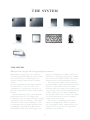
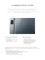
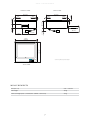
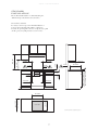
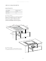
GRAND CUISINE DESIGN GUIDE T H E DE SIG N GU I DE A detailed guide to the world’s most exclusive cooking system W E L C OM E T O G R A N D C U I SI N E The Electrolux Grand Cuisine Cooking System redefines home cooking, bringing the tools and techniques of Michelin-star chefs to the home. The result represents a new pinnacle of design and performance, combining professional capability with intuitive ease of use for the home cook who demands the very best. This design guide will help you to understand the technical specifications of the individual components and provide you with detailed information necessary to design, build and install kitchen furniture and plan utility connections. 3 THE S YSTEM combination ov en bl ast chiller pr ecision vacuum se aler induction ZONE Sur round Induction Zone Se ar hob gas hob stand mixer bespok e v entil ation system THE S YSTEM Harmonious design and integrated performance. High power outputs, precise control, and exceptional hand-built quality make the Grand Cuisine Cooking System unique among home kitchen components. Yet the revolutionary principle behind Grand Cuisine is the way that each component is designed to integrate as part of a distinctive, intuitive and seamless system. System thinking derives directly from professional practice. Leading-edge techniques such as cook-and-chill, vacuum sealing for sous-vide cookery, and combination heat and steam cooking are now in widespread use, thanks to pioneering technologies developed by Electrolux Professional. The same techniques can now be accomplished at home with total confidence, using Grand Cuisine components such as the Blast Chiller, Precision Vacuum Sealer and Combination Oven. The range also allows a wide scope for personal choice. Some cooks prefer to work with the visible flame of the Gas Hob, while for others the power, fast response and easy-to-clean surface of the Induction Zone is ideal. Whatever the chosen appliance, the Grand Cuisine user interface is simple, clear and consistent across all components within the system. The result is a cooking system that allows accomplished cooks to achieve the exceptional, while empowering every cook to excel and enjoy the experience of home entertaining. 4 C ON T E N T S T E C H N IC A L S Y M B O L S 7 C O M BI N AT IO N OV E N 9 BL A S T C H I L L E R 17 I N DUC T IO N Z O N E 23 G A S H OB 31 S U R R OU N D I N DUC T IO N Z O N E 37 S E A R H OB 41 P R E C I SIO N VAC U U M S E A L E R 45 S TA N D M I X E R 49 B E S P OK E V E N T I L AT IO N 51 S TAC K E D I N S TA L L AT IO N 69 G E N E R A L P L A N N I NG NO T E S F O R C OU N T E R T O P I N S TA L L AT IO N 73 S U M M A RY O F T E C H N IC A L R E QU I R E M E N T S 74 5 The Grand Cuisine electrical appliances are designed for household use and are in compliance with the requirements of the following European Community Directives: 2004/108/EC (EMC); 2006/95/EC (LVD); their subsequent amendements and supplements, and with the European Community Standards indicated on each CE Declaration of Conformity CHARACTERISTICS OF POWER SUPPLY The AC power supply to the Grand Cuisine appliances must meet the following conditions: » » max. voltage variation + 6% / -10% » » max. frequency variation +1% » » connection to an efficient ground circuit (≤ 4Ω) The connection to the electrical power supply has to be done in compliance with the current national and local regulations. Each appliance must be protected with dedicated devices against overcurrents (e.g. fuses, thermal magnetic circuit breakers), against direct and indirect contacts (e.g. residual current device, GFI - ground fault interrupter, depending of the type of supply and connection to the ground provided). AMBIENT WORKING CONDITION Class N 32°C , 55% Relative Humidity 6 T EC H N IC A L S Y M B OL S EI CWI AO EI D CWI CWI AO AI AI G TCA EI CWI D Air D EI Vents CWI TCA EI CWI x xx mm CWI AO TCA V AI V EI CWIDrain D D EI TCA TCA DV EI AO Air Inlet TCA V V G EI CWI x xx mm AI x xx mm EI CWI D x xx mm AI D CWI GAir Outlet AI AO G V Water AOCold G Inlet EI TCA TCA V Gas AI Inlet (Standard Gas Connection) G D AI Electricity Inlet (Power D CWI AO Supply)G D CWI x xx mm D x xx mm TCA V EI CWI D x xx mm x Technical Connection Area xx mm Distance from combustible materials 2 3 0 V~ W I R E BrownPhase F N BlueNeutral Yellow/GreenGround 400V 3N~ W IR E BrownPhase R S T N BlackPhase GreyPhase BlueNeutral Yellow/GreenGround 7 x xx mm 8 C OM BI N AT ION OV E N Often described as the ‘“heart” of the kitchen, the Combination Oven is a powerful and precise cooking instrument that delivers total control of heat and humidity. For cooking with convection heat, steam heat, or a combination of both. A E S T H ET IC OV E RV I E W K E Y F E AT U R E S » » Side-opening door » » 4 & 6 mm chamfered, patterned glass » » Solid metal handles » » Interactive touchscreen user interface » » Automatic cleaning system » » Automatic or Manual cooking strategies » » Exact temperature & humidity control » » Patented Lambda sensor enables setting humidity level to exact percentage » » Six-sensor temperature probe » » Removable rack support The appliance is designed for household use and is in compliance with the requirements of the following European Community Directives (1) and their subsequent amendements and supplements, and with the following Standards (2): (1) 2004/108/EC (EMC); 2006/95/EC (LVD) (2) EN 60335-1, EN 60335-2-6; EN 62233:2008; EN 55014-1:2006+A1:2009; EN 55014-2:1997+A1:2001+A2:2008+A1:2009+A2:2009 EN 61000-6-1:2007; EN 61000-3-2;2006 EN 61000-3-3:2008; EN 61000-6-3:2007; EN 50581:2012 9 g r a n d c u i s i n e c o m b i n at i o n ov e n f ron t v iew si d e v i e w MENU 150° 5068%% 120° 120° 16° ° 105 125° ° 00° 00:30 MORE 22 61/64”� 583 mm 60° 00:25 00° START 3 15/32”� 88 mm EI D EI 35 7/16”� 896 mm CW CWI CWI D 33 35/64”� 852 mm V 27 3/16”� 691 mm 5 1/4”� 133 mm 5 1/4”� 133 mm AO 7 3/4”� 197 mm 23 7/8”� 606 mm 23 1/16”� 585 mm 31° 46 75° 90° 1 9/64”� 29 mm 8 1/8”� 206 mm Technical symbols legend on page 7 t op v i e w 28 3/8”� 721 mm 100˚ ME A SUR EMEN TS External size (H × W × D) (including door handle) 606 896 780 mm Cavity (H × W × D) 380 560 520 mm Usable cavity capacity 105 litres Net weight 115 kg Full-load weight (to be considered for cabinet construction) 150 kg 10 3 1/2”� 89 mm g r a n d c u i s i n e c o m b i n at i o n ov e n S TA N DA R D I N S TA L L AT ION Cab. niche (H W D) 590 860 700 mm Thickness of the shelves 40 mm Depth of the shelves 550 mm Max temperature of cabinet panels 60 °C p l a n n i ng no t e s It is recommended to fix the cabinet to the wall. The cabinet panels and shelves must be waterproof. The rear cabinet panels above and below the Combination Oven must be removable for installation and service. The upper part of the oven is predisposed for warm air exit. Do not block these sections. Provide a vent on the upper part of the cabinet. Leave an area of at least 120 cm2. F RON T VIEW LEFT VIEW MIN 120 cm2 V AO 1 37/640 40 mm 1/80 3 mm MIN 3/160 MIN 5 mm REMOVABLE MIN 5 29/320 MIN 150 mm 23 1/40 590 mm C O M B I N AT I O N O V E N NICHE 3 11/320 33 7/80 860 mm 85 mm 21 5/80 550 mm MIN 850 mm MIN 360 Check USB key access on page 13 MIN 5 29/320 MIN 150 mm BL AST CHILLER ARE A IF PRESENT D 21 5/80 550 mm TCA EI CWI MIN 5/80 MIN 16 mm MIN 27 1/20 MIN 700 mm Technical symbols legend on page 7 11 33/640 1 37/640 13 mm 40 mm g r a n d c u i s i n e c o m b i n at i o n ov e n S PEC I A L R EQU I R E M E N T S The figure shows where the cold air intake is taken: pl a n ning not es V Cold air intake V Cold air intake V Cold air intake When the door is open the glass extends 3 mm from the edge of the standard cabinet (900 mm width). When opening the control panel (e.g. when servicing), the panel extends 3 mm from the edge of the standard cabinet (900 mm width). This requirement is important to guarantee correct ventilation. Do not block these sections. 35 7/16� 900 mm SHELF 33 55/64� 860 mm V 90° 11/64� 4,5 mm = 1/8� 3 mm 1 37/64� 40 mm 30 7/8� 784 mm � 3/8� � 10 mm 33 7/8� 860 mm = 21 5/8� 550 mm AO 11 13/16� 300 mm 1/8� 3 mm FRONT SIDE pl a n ning not es In order to protect the shelf it is recommended to use the metal plate. The metal plate is supplied with the Combination Oven. SHELF METAL PLATE FRONT SIDE pl a n ning not es In the case that the appliance is under dynamic stress, a more sturdy fixing to the furniture is necessary. 12 g r a n d c u i s i n e c o m b i n at i o n ov e n pl a n ning not es Access to the USB port is provided at the bottom of the control panel. Ensure that the furniture design allows appropriate access for inserting and removing the USB key. 1 2 3 1 3/160 30 mm 1 9/640 28 mm 4 3/40 120 mm 13 g r a n d c u i s i n e c o m b i n at i o n ov e n A I R OU T L ET Provide external outlet to collect the oven exhaust air “AO”. This will also help avoid humid air and cooking smells inside the kitchen. The Combination Oven is equipped with an air outlet fan. Outlet airflow 150 m3/h Outlet air pressure 10 Pa External outlet pipe diameter 100 mm (3 15/16) Typical temperature 40 °C Peak temperature 60 °C Typical humidity 60% Peak humidity 90% AO V The evacuation of the air must be dimensioned in order to guarantee 150 m3/h airflow and an outlet area of at least 70 cm2. Install an external extractor fan when: » » The pipe ( 100) is more than 1.5 m in length » » There is more than one 90° bend on the pipe Avoid traps in the air outlet pipe in order to prevent build-up of condensation. The air outlet pipe should have a device to prevent cold air backflow and prevent inflow of leaves, insects, etc. CWI D EI Technical symbols legend at page 7 E x t e r n a l Fa n c o n n e c t io n s The exernal extractorfan can be controlled through the oven connections K-IN and K-OUT by means of an external relay. The grommet indicated in the figure is for the insertion of an electrical cable for an external relay. The grommet is located near the electrical cable. Technical characteristics of the contact »» Normally Open »» Max Voltage 250V »» Max Power 0,1kW 14 I m p o r ta n t Do not directly connect the auxiliary fan to the oven, use the oven connection to connect the external relay, and connect the auxiliary fan to the external relay. The oven can not supply power to the auxiliary fan. E L EC T R IC I T Y Power supply 400 3N~ 50/60 Hz Max power 6.0 kW Max current 13.2 A pl a n ning not es The Combination Oven is designed to be connected to the power supply in a permanent way by means of a flexible cable. It is necessary to install an appropriate switch to disconnect the appliance. This switch must be installed in the building’s permanent electrical system, in the immediate vicinity of the appliance. 15 g r a n d c u i s i n e c o m b i n at i o n ov e n I N L ET WAT E R Cold water inlet 3/4 Max temperature 20 °C Pressure 1.5– 6 bar Max water flow 2.6 l/min Max water consumption per cleaning cycle 18 l pl a n ning not es The inlet water must be drinking water, and meet the following requirements: Total hardness 0.5–5 °f 0.28–2.81 °dH Chloride Cl – < 10 ppm < 10 mg/l Conductivity (20 °C) 50 –2000 µS/cm 5–200 mS/m pH >7 In some areas a water treatment system may be needed to prevent damage to the system. Data on total hardness, conductivity, Chloride Cl – and pH, which are readily available from the water supply company, are needed for the evaluation. Provide the cold water inlet pipe (CWI) with a water tap in an easily reachable position close to the oven. DR A I N I NG Oven drain outlet 25 mm Drain temperature requirement 100 °C Drain pipe’s slope Min 5% pl a n ning not es MIN 120 MIN 300 mm The drain connection must be equipped with a siphon device. Leave a minimum of 300 mm height between the oven drain outlet and the drain connection point. The drain pipe is not supplied with the Combination Oven. It is suggested to install an external air gap. D 16 BL A S T C H I L L E R The Blast Chiller is a powerful, rapid blast chiller and freezer, even for food taken directly from the oven. A key component in the cook-and-chill process. A E S T H ET IC OV E RV I E W K E Y F E AT U R E S » » Side-opening door » » 4 & 6 mm chamfered, patterned glass » » Solid steel handles » » Interactive touchscreen user interface » » Automatic or Manual chilling strategies » » Three-sensor Food Probe enables chilling or freezing to exact temperatures » » Removable rack support » » Condensation collection tray The appliance is designed for household use and is in compliance with the requirements of the following European Community Directives (1) and their subsequent amendements and supplements, and with the following Standards (2): (1) 2004/108/EC (EMC); 2006/95/EC (LVD) (2) EN 60335-1; EN60335-2-24; EN 55014-1:2006 + A1:2009 EN EN 61000-6-3:2007 EN 61000-3-2:2006 + A1:2009 + A2:2009 EN 61000-3-3:2008 EN 55014-2:1997 + A1:2001 + A2:2008; EN 61000-6-1:2007 17 gr a n d cuisin e bl ast chil l er f ron t v iew si d e v i e w MENU 150° 5068%% 120° 120° 00° 3 5/16� 84 mm START 3 3/16� 80 mm EI EI 35 9/32� 896 mm 33 5/8� 854 mm 4 23/32� 420 mm 27 5/32� 690 mm 3 1/2� 89 mm 11 7/8� 302 mm AO 5 1/2� 140 mm 8 1/16� 205 mm 1 5/32� 29 mm 3/4� 17 mm Technical symbols legend on page 7 100˚ 28 3/8� 721 mm t op v i e w ME A SUR EMEN TS External size (H W D) (including door handle) 606 896 779 mm Cavity (H W D) 459 557 528 mm Usable cavity capacity 100 litres Net weight 100 kg Full-load weight (to be considered for cabinet construction) 135 kg 18 23 7/8� 606 mm 00° 00:30 MORE 23 1/16� 585 mm 22 21/32� 576 mm 46° 75° 31° 60° 00:25 16 29/64� 418 mm 16° ° 105 125° 90° gr a n d cuisin e bl ast chil l er L E F T H I NG E D D O OR V E R S ION f ron t v iew si d e v i e w MENU 150° 5068%% 120° 00° 3 5/16”� 84 mm START 27 5/32”� 690 mm 3 1/2”� 89 mm 3 3/16”� 80 mm 33 5/8”� 854 mm 4 23/32”� 420 mm 11 7/8”� 302 mm EI EI 35 9/32”� 896 mm AO 5 1/2”� 140 mm 599F02D00 1 5/32”� 29 mm 8 1/16”� 205 mm 3/4”� 17 mm 28 3/8”� 721 mm 100˚ t op v i e w Technical symbols legend on page 7 ME A SUR EMEN TS External size (H W D) (including door handle) 606 896 779 mm Cavity (H W D) 459 557 528 mm Usable cavity capacity 100 litres Net weight 100 kg Full-load weight (to be considered for cabinet construction) 135 kg 19 23 7/8”� 606 mm 00° 00:30 MORE 23 1/16”� 585 mm 46° 75° 22 21/32”� 576 mm 16° ° 105 31° 60° 00:25 16 29/64”� 418 mm 120° 125° 90° gr a n d cuisin e bl ast chil l er S TA N DA R D I N S TA L L AT ION Cab. niche (H W D) 590 860 700 mm Thickness of the shelves 40 mm Depth of the shelves 550 mm pl a n ning not es It is recommended to fix the cabinet to the wall. The cabinet panels and shelves must be waterproof. The rear cabinet panels above and below the Blast Chiller must to be removable for installation and service. Provide a vent on the upper and lower part of the cabinet with an area of at least 560 cm2. LEFT VIEW F RON T VIEW MIN 560 cm2 V MIN 5 29/320 MIN 150 mm REMOVABLE 1 37/640 40 mm 21 5/80 550 mm 1/80 3 mm MIN 3/160 MIN 5 mm 21 5/80 550 mm OVEN ARE A IF PRESENT 21 5/80 550 mm BL AST CHILLER NICHE 23 1/40 590 mm 33 7/80 860 mm MIN 5 29/320 MIN 150 mm 21 5/80 550 mm TCA V MIN 560 cm2 EI MIN 27 1/20 MIN 700 mm MIN 5/80 MIN 16 mm 33/640 1 37/640 13 mm 40 mm Technical symbols legend on page 7 20 FRONT SIDE gr a n d cuisin e bl ast chil l er S PEC I A L R EQU I R E M E N T S pl a n ning not es In order to protect the shelf it is recommended to use the metal plate. The metal plate is supplied with the Blast Chiller. SHELF METAL PLATE FRONT SIDE pl a n ning not es In the case that the appliance is under dynamic stress, a more sturdy fixing to the furniture is necessary. p l a n n i ng no t e s When the door is open the glass extends 3 mm from the edge of the standard cabinet (900 mm width). When opening the control panel (e.g. when servicing), the panel extends 3 mm from the edge of the standard cabinet (900 mm width). 35 7/16 900 mm 33 55/64 860 mm 1/8 3 mm 1/8 3 mm 21 gr a n d cuisin e bl ast chil l er A I R I N L ET Cabinet base air inlet min 560 cm2 P l a n n i ng no t e Provide an air inlet in the area below the appliance. The air inlet for the Blast Chiller must have an area of at least 560 cm2. A I R OU T L ET Cooling airflow 400 m3/h Peak temperature 60 °C Cabinet air outlet MIN 560 cm2 P l a n n i ng no t e Do not mount the cabinet adjacent to the ceiling. Leave an area of at least 560 cm2 to discarge the hot air. E L EC T R IC I T Y Power supply 230V~ 50 Hz Max power 0.87 kW Max current 4.5 A pl a n ning not es The Blast Chiller is designed to be connected to the power supply in a permanent way by means of flexible cable. It is necessary to install an appropriate switch to disconnect the appliance. This switch must be installed in the building’s permanent electrical system, in the immediate vicinity of the appliance. 22 I N DUC T ION ZON E The Induction Zone is a large induction cooktop offering high power and complete flexibility. Features controllable safe heat using pot detection technology. A E S T H ET IC OV E RV I E W K E Y F E AT U R E S » » 4 mm chamfered, patterned glass » » Stainless steel frame » » Hand-built » » Interactive touchscreen user interface » » Zoneless cooking » » Pre-set configurations for quick start » » Large 260 mm diameter coils for uniform heating » » Pot recognition system The appliance is designed for household use and is in compliance with the requirements of the following European Community Directives (1) and their subsequent amendements and supplements, and with the following Standards (2): (1) 2004/108/EC (EMC); 2006/95/EC (LVD) (2) EN 60335-1; EN 60335-2-6; EN 50581; EN 55014-1:2007; EN 55014-2 :1998 + A1:2002 + IS 1:2007; EN 61000-3-2:2005; EN 61000-3-3:1997 + A1:2002 + A2/ IS1:2006; EN 61000-3-11:2001; EN 55011:1999 + A1:2000 + A2 :2003; EN 61000-4-2:1996 + A1:2001 + A2:2003; EN 61000-4-4:2006; EN 61000-4-6 :1997 + A1:2001 + IS1:2005; EN 61000-4-11:2006) 23 g r a n d c u i s i n e i n d uc t i o n z o n e bottom view � 4 9/64” 105 mm EI 20 5/16”� 516 mm 51/64”� 20 mm AO � 3 15/16”� � 100 mm AI side v iew 7/8”� 22 mm 5 3/16”� 9 mm 5/8”� 17 mm 16 27/32”� 428 mm 17 3/16”� 437 mm f ron t view EI 2 1/2”� 63 mm � 5 33/64”� 140 mm 3 1/8”� 130 mm EI 19 5/16”� 491 mm 2 49/64” 70 mm 37 11/16”� 957 mm 40 5/32”� 1020 mm 20 7/8”� 530 mm 41 5/16”� 1050 mm Technical symbols legend on page 7 top view ME A SUR EMEN TS External size (W D) 1050 530 mm Net weight (kg) 70 kg Full-load weight (to be considered for cabinet construction) 100 kg 24 g r a n d c u i s i n e i n d uc t i o n z o n e S TA N DA R D I N S TA L L AT ION 41 5/160 1050 mm MAX 130� MAX 330 mm 37 7/80� 962 mm 2 1/80� 59 mm 2 1/80� 59 mm 16 27/320 428 mm 2 1/80� 59 mm (MAX 2 23/640) MIN 1 3/160 (MAX 60 mm) MIN 30 mm MIN 180 MIN 457 mm MIN 1 37/640 MIN 40 mm V MIN 1 37/640� MIN 40 mm 14 13/160 376 mm 20 1/80 511 mm 2 15/160� 75 mm V MIN 314 cm² (Cold air intake) MIN 314 cm² (Warm air exhaust) � [4 1/40 � [108 mm MIN 5 1/80 MIN 130 mm (MAX 2 23/640) MIN 1 3/160 (MAX 60 mm) MIN 30 mm MIN 300 MIN 762 mm Electrolux Grand Cuisine recommends using the dimensions specified in the above sketches. MIN 27 1/20 MIN 700 mm Part. A Part. B CUT-OUT Technical symbols legend on page 7 Part. A, Part. B on next page 25 Part. A 39 3/40 1009 mm 39 5/160 998 mm 2 9/640 54,5 mm CUT-OUT Part. B 4” /6 49 m 9 8m 24 60 5/1 mm 8 4” /6 49 m 9 8m 24 80 3/ m m 10 0 /16 m 15 3,5 m 2 3/8” 10 mm UT 80 3/ m m 10 26 0 64 9/ m 2 5m , 54 -O UT C 0 /64 45 8 mm 1 60 5/1 mm 8 19 1/20 496 mm � 3/80 � 10 mm 15 1/40 387 mm Part. B 5/640 2 mm MIN 27 1/20 MIN 700 mm 37 7/80 962 mm g r a n d c u i s i n e i n d uc t i o n z o n e S PEC I A L R EQU I R E M E N T S E L EC T R IC I T Y Power supply 400 3N~ 50 Hz Max power 12 kW Max current 18 A p l a n n i ng no t e s p l a n n i ng no t e s The Induction Zone is designed to be connected to the power supply in a permanent way by means of flexible cable. It is necessary to install an appropiate switch to disconnect the appliance. This switch must be installed in the building’s permanent electrical system, in the immediate vicinity of the appliance. For safety reasons respect the minimum distances between the wall cupboards and the countertop. Provide an opening (like a flip door or removable panel) to provide access for service. CUT-OUT ” 37 7/8 m� 962 m 19 1/2” 496 mm� 27 pl a n ning not es In the case the appliance is under dynamic stress it is recommended to install the special frame, available as accessory, designed to avoid pot, pan sliding out of cooking surface. I m p o r ta n t The special frame must be connected to an efficient ground electrical system. 28 The worktop must be prepared with appropriate holes for special frame fixing. 42 7/160 1078 mm 14 5/80 372 mm 12 3/80 314 mm 12 3/80 314 mm 2 5/160 58 mm 1/40 6 mm 2 5/160 58 mm 13 1/80 334 mm 1 1/80 29 mm 14 5/80 372 mm 18 1/40 464 mm 80 3/ mm 0 [1 CUT-OUT SPECIAL FRAME PASS-THROUGH HOLES 29 10 26 mm 1 5/160 33 mm 80 3/ mm 10 [ 30 G A S HOB Large, professional-standard gas hob with continuous pan support and unique Flower Flame that adapts to all pan sizes. A E S T H ET IC OV E RV I E W K E Y F E AT U R E S » » Solid stainless steel tub » » Cast-iron pan support » » Hand built » » Combination of matte and glossy surfaces » » Patented Flower Flame burners that adjust to the size and form of the cookware The appliance is designed for household use and is in compliance with the requirements of the following European Community Directives (1) and their subsequent amendements and supplements, and with the following Standards (2): (1) 2004/108/EC (EMC); 2006/95/EC (LVD);2009/142/EC (GAD) (2) EN 60335-1; EN 60335-2-102; EN 50581; EN 30-1-1 EN 55014-1:2007; EN 55014-2 :1998 + A1:2002 + IS 1:2007; EN 61000-3-2:2005; EN 61000-3-3:1997 + A1:2002 + A2/ IS1:2006; EN 61000-3-11:2001; EN 55011:1999 + A1:2000 + A2 :2003; EN 61000-4-2:1996 + A1:2001 + A2:2003; EN 61000-4-4:2006; EN 61000-4-6 :1997 + A1:2001 + IS1:2005; EN 61000-4-11:2006 31 gr a n d cu isi n e gas hob f ron t v iew 7/8 22 mm 7/8 22 mm 7/8 22 mm 12 9/32 312 mm 8 3/8 212 mm 1 5/8 42 mm 7/8 22 mm si d e v i e w EI G 1 7/8 47 mm G EI UNI ISO 7/1-R 1/2 39 5/8 1006 mm 3 7/8 99 mm 19 1/8 486 mm 20 7/8 530 mm 41 5/16 1050 mm Technical symbols legend on page 7 t op v i e w ME A SUR EMEN TS Size (W D) 1050 530 mm Net weight 40 kg Full-load weight (to be considered for cabinet construction) 90 kg Product class 3 32 gr a n d cu isi n e gas hob Electrolux Grand Cuisine recommends using the dimensions specified in the above sketches. pl a n ning not es For safety reasons respect the minimum distances between the wall cupboards and the countertop. The contact area between the Gas Hob frame and the countertop can reach 130 °C. Ensure that the countertop material has adequate temperature resistance. Provide a dedicated channel for the primary air required for the combustion process. It should have an area of at least 500 cm2. Provide a front opening (like a flip door or removable panel) to provide access for service. MIN 1 37/640 (MAX 40) MIN 40 mm (MAX 102 mm) S TA N DA R D I N S TA L L AT ION 6 45/640 170 mm 6 45/640 170 mm 19 7/160 493 mm 11/320 59 mm Part. A V MIN 13 3/40 MIN 350 mm Part. C Part. B MIN 1 3/160 MIN 30 mm MIN 1 3/160 MIN 30 mm MIN 500 cm2 (Cold air intake) MIN 500 cm2 (Cold air intake) Part. C 19 7/160 493 mm CUT-OUT V MIN 1 37/640 (MAX 40) MIN 40 mm (MAX 102 mm) 39 3/40 1010 mm MIN 27 1/20 MIN 700 mm (MAX 1 9/160) MIN 1 3/160 (MAX 40 mm) MIN 30 mm MIN 180 MIN 457 mm MAX 130 MAX 330 mm CUT-OUT 3 9/640 80 mm MIN 300 MIN 762 mm 41 5/160 1050 mm MAX 1 3/160 MAX 30 mm 9/160 14 mm Ø 3/160 6 mm Part. B 25/640 10 mm 25/640 10 mm 25/640 10 mm 25/640 10 mm 3 9/640 80 mm Part. A 1/80 3 mm 2 3/40 70 mm 9/160 14 mm 14 1/80 359 mm 11 3/160 284mm 90° CUT-OUT 14 1/80 359 mm 40 9/160 1030 mm Holes dimension Technical symbols legend on page 7 33 gr a n d cu isi n e gas hob S PEC I A L R EQU I R E M E N T S E L EC T R IC I T Y G A S R EQU I R E M E N T S Power supply 230V~ 50 Hz Max current <1A p l a n n i ng no t e s The Gas Hob is designed to be connected to the power supply in a permanent way by means of flexible cable. It is necessary to install an appropriate switch to disconnect the appliance. This switch must be installed in the building’s permanent electrical system, in the immediate vicinity of the appliance. CONDITIONS Gas supply connection 1/2 Burner’s max power 2 3 kW + 3 5.5 kW [gas] Total max power 22.5 kW [gas] p l a n n i ng no t e s The Gas Hob is configured with nozzles for natural gas. The nozzles for LPG configuration are supplied with the Gas Hob as included accessories. SUPPLY PRESSURE GAS MAX CONSUMPTION Dry Gas at 15 °C and 1013 mbar Minimum (mbar) Nominal (mbar) Maximum (mbar) G31 50.37 MJ/Kg 25 37 45 1,61 Kg/h G30 49.47 MJ/Kg 20 28-30 35 1,64 Kg/h G20 37.38 MJ/mc 17 20 25 2,14 m3/h 3 4 CUT-OUT 39 3/4”� m 1010 m 19 7/16”� 493 mm ”� 40 9/16 m m 0 3 0 1 (MAX 1 9/160) MIN 1 3/160 (MAX 40 mm) MIN 30 mm 2 3/4”� 70 mm SIDE VIEW 1/80 3 mm 4 23/320 120 mm FRONT PANEL KNOB 1 37/64” 40 mm MAX 1 3/160 MAX 30 mm 4 23/32” 120 mm 2” 41 11/3 m 1050 m 35 36 S U R ROU N D I N DUC T ION ZON E The instant power of induction heat meets the smooth contours of an all-round cooking surface for effortless cooking, frying and steaming. A E S T H ET IC OV E RV I E W K E Y F E AT U R E S » » Evenly contoured rounded surface » » 4 mm chamfered, patterned glass » » Stainless steel frame » » Hand built » » Interactive touchscreen user interface » » Powerful, safe and energy-efficient » » Rapid heating and precise temperature control » » Pot detection technology » » Fast, even cooking with no hot spots » » Healthier – needs less oil for sauté cooking The appliance is designed for household use and is in compliance with the requirements of the following European Community Directives (1) and their subsequent amendements and supplements, and with the following Standards (2): (1) 2004/108/EC (EMC); 2006/95/EC (LVD) (2) EN 60335-1; EN 60335-2-6; EN 50581; EN 55014-1:2007; EN 55014-2 :1998 + A1:2002 + IS 1:2007; EN 61000-3-2:2005; EN 61000-3-3:1997 + A1:2002 + A2/ IS1:2006; EN 61000-3-11:2001; EN 55011:1999 + A1:2000 + A2 :2003; EN 61000-4-2:1996 + A1:2001 + A2:2003; EN 61000-4-4:2006; EN 61000-4-6 :1997 + A1:2001 + IS1:2005; EN 61000-4-11:2006 37 g r a n d c u i s i n e s u r r o u n d i n d uc t i o n z o n e bot tom view �1 1/80 28 mm AI ��13 7/80 327 mm EI 12 3/40 324 mm �1 1/80 28 mm f ron t v iew 9/160� 15 mm 13/160� 20 mm 19 5/160� 490 mm 13/160� 20 mm AO 2 53/640 72 mm �1 9/160 40 mm 120 305 mm 5/160� 9 mm 9/160� 15 mm 14 15/160 � 380 mm si d e v i e w EI EI AI �4 61/640 126 mm AI 7 29/320 201 mm 20 7/80� 530 mm Technical symbols legend on page 7 MENU 16 1/80� 410 mm t op v i e w ME A SUR EMEN TS Size (W D) 410 530 mm Net weight 20 kg Full-load weight (to be considered for cabinet construction) 25 kg 38 g r a n d c u i s i n e s u r r o u n d i n d uc t i o n z o n e S TA N DA R D I N S TA L L AT ION Electrolux Grand Cuisine recommends using the dimensions specified in the above sketches. pl a n ning not es For safety reasons respect the minimum distances between the wall cupboards and the countertop. Provide a front opening (like a flip door or removable panel) to provide access for service. MAX 130� MAX 330 mm 2 7/80� 74 mm 2 1/80� 59 mm 2 1/80� 59 mm MIN 8/90� MIN 23 mm 2 1/80� 59 mm MIN 8/90� MIN 23 mm [ 4 1/40 � [108 mm MIN 100 cm2 (Cold air intake) V 12 19/320 320 mm V MIN 100 cm² (Warm air exaust) CUT-OUT 19 11/160� 500 mm MIN 27 1/20� MIN 700 mm 15 1/20� 393 mm 19 11/160� 500 mm (MAX 2 23/64�) MIN 1 3/160� (MAX 60 mm) MIN 30 mm 2 7/80� 74 mm MIN 5 1/80 MIN 130 mm MIN 180� MIN 457 mm MIN 300 MIN 762 mm 21 1/40 540 mm Technical symbols legend on page 7 39 g r a n d c u i s i n e s u r r o u n d i n d uc t i o n z o n e S PEC I A L R EQU I R E M E N T S E L EC T R IC I T Y Power supply 230V~ 50 Hz Max power 3.5 kW Max current 15 A pl a n ning not es The Surround Induction Zone is designed to be connected to the power supply in a permanent way by means of flexible cable. It is necessary to install an appropriate switch to disconnect the appliance. This switch must be installed in the building’s permanent electrical system, in the immediate vicinity of the appliance. ” 15 1/2 m 393 m 19 11/16” 500 mm CUT-OUT MENU 40 S E A R HOB On the Sear Hob you can cook without a pan – the energy-efficient chrome-plated surface heats directly and swiftly with an even temperature right across the surface. A E S T H ET IC OV E RV I E W K E Y F E AT U R E S » » 12 mm thick chrome-plated surface » » 4 mm chamfered, patterned glass » » Handcrafted stainless steel frame » » Hand built » » Interactive touchscreen user interface » » Hidden collection tray » » Energy efficient and won’t stain or dent thanks to its chrome plating The appliance is designed for household use and is in compliance with the requirements of the following European Community Directives (1) and their subsequent amendements and supplements, and with the following Standards (2): (1) 2004/108/EC (EMC); 2006/95/EC (LVD) (2) EN 60335-1; EN 60335-2-6; EN 50581; EN 55014-1:2007; EN 55014-2 :1998 + A1:2002 + IS 1:2007; EN 61000-3-2:2005; EN 61000-3-3:1997 + A1:2002 + A2/ IS1:2006; EN 61000-3-11:2001; EN 55011:1999 + A1:2000 + A2 :2003; EN 61000-4-2:1996 + A1:2001 + A2:2003; EN 61000-4-4:2006; EN 61000-4-6 :1997 + A1:2001 + IS1:2005; EN 61000-4-11:2006 41 gr a n d cu isi n e se a r hob 9/16 15 mm 19 11/16 500 mm 9/16 15 mm 10 7/16 265 mm 0 3/8 10 mm 6 7/16 164 mm 5 11/16 144.5 mm 3 15/16 100 mm EI 7 11/16 194.5 mm 1/4 6 mm 3/4 18.5 mm 3 13/16 97 mm 3/4 18.5 mm 19 13/16 503 mm si d e v i e w 5/16 9 mm f ron t v iew Grease Tray EI 10 7/16 265 mm 20 7/8 530 mm 21 1/4 540 mm MENU Technical symbols legend on page 7 t op v i e w ME A SUR EMEN TS Size (W D) 540 530 mm Net weight 30 kg Full-load weight (to be considered for cabinet construction) 35 kg 4 2 gr a n d cu isi n e se a r hob S TA N DA R D I N S TA L L AT ION Electrolux Grand Cuisine recommends using the dimensions specified in the above sketches. p l a n n i ng no t e s For safety reasons respect the minimum distances between the wall cupboards and the countertop. Provide an opening (like a drawer or flip door) to pull out the grease tray and provide access for service. 3 1/16 78.5 mm 2 1/8 59 mm MAX 13 MAX 330 mm 2 1/8 59 mm 2 1/8 59 mm 20 1/16 510 mm (MAX 2 23/64) MIN 1 3/16 (MAX 60 mm) MIN 30 mm 3 1/16 78.5 mm 5 1/8 145 mm MIN 18 MIN 457 mm MIN 30 MIN 762 mm 26 3/8 670 mm CUT-OUT 7 1/2 190 mm MIN 8/9 MIN 23 mm 4 5/8 118 mm 5 3/8 136 mm MIN 8/9 MIN 23 mm CUT-OUT 20 1/16 510 mm MIN 27 1/2 MIN 700 mm 20 3/16 513 mm Technical symbols legend on page 7 43 gr a n d cu isi n e f ry top cook top S PEC I A L R EQU I R E M E N T S E L EC T R IC I T Y Power supply 400V 3N~ 50 Hz Max power 3.5 kW Max current 5A p l a n n i ng no t e s The Sear Hob is designed to be connected to the power supply in a permanent way by means of flexible cable. It is necessary to install an appropriate switch to disconnect the appliance. This switch must be installed in the building’s permanent electrical system, in the immediate vicinity of the appliance. 6” 20 3/1 m 513 m 20 1/16” 510 mm CUT-OUT 4 5/8” 118 mm 7 1/2” m 190 m MENU MENU pl a n ning not es In the case the appliance is under dynamic stress it is recommended to fix the Grease tray so it cannot move. 4 4 Grease tray PR EC I SION VAC U U M S E A L E R The Precision Vacuum Sealer is the key to sous-vide cookery, sealing food, nutrients and liquids in an airtight pouch to ensure the highest levels of taste, quality and texture. A E S T H ET IC OV E RV I E W K E Y F E AT U R E S » » 4 mm chamfered, patterned glass » » Stainless steel frame » » Interactive touchscreen user interface » » Hand-built, minimal gaps between surfaces » » Variable vacuum level » » Professional performance The appliance is designed for household use and is in compliance with the requirements of the following European Community Directives (1) and their subsequent amendements and supplements, and with the following Standards (2): (1) 2004/108/EC (EMC); 2006/95/EC (LVD) (2) EN 60335-1; EN 60335-2-45; EN 55014-1:2006 + A1:2009; EN 61000-3-2:2006; EN 61000-3-3:2008; EN 55014-2:1997 + A1:2001 + A2:2008; EN 62233:2008 45 f ron t v iew 17 23/32”� 450 mm 25/64”� 10 mm si d e v i e w 15”� 382 mm g r a n d c u i s i n e p r e c i s i o n vac u u m s e a l e r EI EI 13 1/2”� 342 mm 18 21/32”� 474 mm 3 5/32”� 80 mm 22 13/64”� 564 mm 20 7/8”� 530 mm t op v i e w MENU Technical symbols legend on page 7 16 1/9”� 410 mm ME A SUR EMEN TS External size (W D) 410 554 mm Cavity size (H W D) 342 262 118 mm Usable cavity 10 litres Net weight 50 kg Full-load weight (to be considered for cabinet construction) 70 kg 46 MIN 13/160 MIN 20 mm 200 510 mm MIN 13/160 MIN 20 mm MIN 2 3/40 MIN 70 mm 20 3/320 510 mm MIN 27 1/20 MIN 700 mm 15 1/30 389 mm CUT-OUT Technical symbols legend on page 7 S TA N DA R D I N S TA L L AT ION Part. A Part. A 2 21/640 58.5 mm 1/40 6,5 mm R 13/640 R 5 mm 2 11/640 55 mm R 63/640 R 25 mm 19/640 7,5 mm t op v i e w 47 1 38 5 1 9 /30 m m C U TO U T 0 20 mm 0 51 3/640 R 1 mm 0 32 9/ m 20 3 m 52 2 15 1 55 1/6 404 7/8 m 40 m 0 m m 2 25 10 5 11/ 5 0 5 64 m 0 m m m 1/20 12 mm 1/100 2.5 mm Electrolux Grand Cuisine recommends using the dimensions specified in the above sketches. (MAX 2 23/640) MIN 1 3/160 (MAX 60 mm) MIN 30 mm MIN 180 MIN 457 mm g r a n d c u i s i n e p r e c i s i o n vac u u m s e a l e r g r a n d c u i s i n e p r e c i s i o n vac u u m s e a l e r S PEC I A L R EQU I R E M E N T S E L EC T R IC I T Y Power supply 230V~ 50 Hz Max power 0.75 kW Max current 3.2 A p l a n n i ng no t e s The Precision Vacuum Sealer is designed to be connected to the power supply in a permanent way by means of flexible cable. It is necessary to install an appropriate switch to disconnect the appliance. This switch must be installed in the building’s permanent electrical system, in the immediate vicinity of the appliance. pl a n ning not es Provide an opening (like a flip door or removable panel) to provide access for service. 48 S TA N D M I X E R Restaurant quality-performance and durability, accurate speed, special planetary movement and a whisper-quiet motor. A E S T H ET IC OV E RV I E W K E Y F E AT U R E S » » Full metal body » » Stainless steel tools, bowl, safety bowl guard » » Planetary movement » » Ergonomic patented bowl lift system and knobs linked to safety bowl guard opening » » Removable safety bowl guard in stainless steel » » Asynchronous motor driven by inverter with energy saving system » » Soft speed variation by control knob The appliance is designed for household use and is in compliance with the requirements of the following European Community Directives (1) and their subsequent amendements and supplements, and with the following Standards (2): (1) 2004/108/EC (EMC); 2006/95/EC (LVD) (2) EN 60335-1; EN 60335-2-14; EN 55014-1: 2006 + A1: 2009;EN 55014-2: 1997 + A1: 2007 + A2: 2008 EN 61000-3-2: 2006 + A1 : 2009 + A2: 2009 EN 61000-3-3: 2008; EN 62233:2008; EN 61000-4-2: 2009 EN 61000-4-4: 2004 + A1:2010; EN 61000-4-5: 2006; EN 61000-4-11: 2004 49 g r a n d c u i s i n e s ta n d m i x e r 13 5/64 350 mm 17 1/5 437 mm 22 43/64 576 mm f ron t view 5 1/14 129 mm 8 3/14 208 mm 9 8/9 252 mm 15 5/8 397 mm side v iew ME A SUR EMEN TS Size (H W D) 437 312 397 mm Net weight 18 kg 12 1/3 312 mm top view S PEC I A L R EQU I R E M E N T S E L EC T R IC I T Y Power supply 208 – 240V~ 50/60Hz Max power 0.45 kW Max current 2.1 A Noise 64 dB(A) p l a n n i ng no t e s The Stand Mixer is designed to be connected to a socket by means of flexible cable with a plug. 50 BE S P OK E V E N T I L AT ION The Grand Cuisine ventilation system offers the same degree of high-powered odour and grease control capabilities found in professional kitchens, with the added benefits of low noise and attractive design, so nothing will detract from a pleasurable ambiance in the kitchen. A E S T H ET IC OV E RV I E W K E Y F E AT U R E S » » Stainless steel and glass hood design perfectly » » Ventilation systems tailored to meet complements cooking appliances » » Wall, island and ceiling configurations » » Hand-built individual needs » » Powerful yet quiet running motors » » Highly efficient filters for grease and cooking aromas » » Remote control The appliance is designed for household use and is in compliance with the requirements of the following European Community Directives (1) and their subsequent amendements and supplements, and with the following Standards (2): (1) 2004/108/EC (EMC); 2006/95/EC (LVD) (2) EN 60335-1:2002 + A1:2004 + A11:2004 + A2:2006 + A12:2006 + A13:2008 + A14:2010 + A15:2011 EN 60335-2-31:2003 + A1:2006 + A2:2009 EN 55014-1:2006 + A1:2006 + A2:2011 EN 55014-2:1997 + A1:2001 + A2:2008 + IS1:2007 EN 61000-3-2:2006 + A1:2009 + A2:2009 EN 61000-3-3:2008 51 g r a n d c u i s i n e B e s p o k e V e n t i l at i o n wa l l m o d e l – 1 c h i m n e y Dg bot tom view f ron t view side v iew Lc Dc MIN 24 5/64� MIN 630 mm EI Lg Technical symbols legend on page 7 52 g r a n d c u i s i n e B e s p o k e V e n t i l at i o n wa l l m o d e l – 2 c h i m n e y s Dg bot tom view f ron t view Lc side v iew Lc EI Dc MIN 24 5/64� MIN 630 mm Ic Lg Technical symbols legend on page 7 53 g r a n d c u i s i n e B e s p o k e V e n t i l at i o n isl a n d model – 1 chim n ey Dg bot tom view f ron t view EI EI Dc MIN 24 5/64� MIN 630 mm Lc side v iew Lg Technical symbols legend on page 7 5 4 g r a n d c u i s i n e B e s p o k e V e n t i l at i o n isl a n d model – 2 chim n eys Dg bot tom view f ron t view EI side v iew EI EI Lc Lc Dc MIN 24 5/64� MIN 630 mm Ic Lg Technical symbols legend on page 7 55 g r a n d c u i s i n e B e s p o k e V e n t i l at i o n WA L L/ I S L A N D HO OD S ME A SUR EMEN TS Model Hood (Glass) Hood (Chimney) Lg (mm) Dg (mm) Lc (mm) Dc (mm) Axle base Ic (mm) Blower Blower outlet n Q (m³/h) n (mm) Filter n Weight (kg) 1 Chimney 1500 700 510 300 – 1 1200 1 200 1 65 2 Chimneys 1900 700 410 300 719 2 1200 2 200 2 110 2 Chimneys 2100 700 410 300 719 2 1200 2 200 2 115 2 Chimneys 2600 700 510 300 1038 2 1200 2 200 2 125 pl a n ning not es Grand Cuisine Wall/Island hoods are recommended for use with Grand Cuisine induction and gas cooktops and integrated modules. These hoods have a customised flue that allows you to reach a ceiling height of 2.4 m to 3.0 m with a finished look. The hoods are available with an internal or external blower. The internal blower version is also available with recirculated configuration. The necessary hood size depends on the cooking unit, the volume of air that needs to be moved and the length of the duct run. Consult pre-sales for specific installation and ducting applications. 56 g r a n d c u i s i n e B e s p o k e V e n t i l at i o n c e i l i n g m o d e l 70 0 19 19/64� 490 mm 3/14� 5 mm 27 1/2� 700 mm 20 55/64� 530 mm R EI R 5/ 4 32� m m bot tom view 64 61/64� 1650 mm f ron t view side v iew 24 5/64� 630 mm Dc 62 13/64� 1580 mm Lc 1 3/8� 35 mm 1 3/8� 35 mm 57 1/15� 1 mm EI Hc EI g r a n d c u i s i n e B e s p o k e V e n t i l at i o n c e i l i n g m o d e l 950 19 19/64� 490 mm 37 2/5� 950 mm 30 5/7� 780 mm R 3/14� 5 mm 64 61/64� 1650 mm f ron t view side v iew EI 34 9/14� 880 mm EI Dc 62 13/64� 1580 mm Hc 1 3/8� 35 mm 58 Lc 1 3/8� 35 mm 14 9/16� 370 mm 1/15� 1 mm EI R 5/ 4 32� m m bot tom view g r a n d c u i s i n e B e s p o k e V e n t i l at i o n C E I L I NG HO OD S ME A SUR EMEN TS Model External Dimension L (mm) D (mm) Cut Out Dimension L (mm) D (mm) Blower (m³/h) Filter n Weight (kg) 700 1650 700 1590 640 2 850 3 65 950 1650 950 1590 890 2 850 3 90 Motor Type Frame Height Hc (mm) Channel’s Dimension Lc (mm) Dc (mm) External 200 300 110 Internal 200 220 90 Recirculation 250 220 90 pl a n ning not es Grand Cuisine cooktop ceiling hoods are recommended for use with Grand Cuisine induction and gas cooktops and integrated modules. The hoods are available with an internal or external blower. The internal blower version is available also with recirculated configuration. The necessary hood size depends on the cooking unit, the volume of air that needs to be moved and the length of the duct run. The exhaust connection can be placed on all four side faces. Consult pre-sales for specific installation and ducting applications. 59 g r a n d c u i s i n e B e s p o k e V e n t i l at i o n S PEC I A L R EQU I R E M E N T S E L EC T R IC I T Y Model Power supply Nominal power (kW) Max current (A) Blower n Q (m³/h) Island/Wall 1 Chimney 230V~ 50 Hz 0.250 1.1 1 1200 Island/Wall 2 Chimneys 230V~ 50 Hz 0.500 2.2 2 1200 Ceiling Internal blower 230V~ 50 Hz 0.850 4 2 850 Ceiling External blower 230V~ 50 Hz – – – E L E C T R IC A L R E QU I R E M E N T S Electrical connections must correspond with local requirements for indoor installations. National or local regulations set by competent supervisory authorities must be observed. The connection must be made in accordance with the electrical diagram. The hoods are designed to be connected to a fixed socket by means of a flexible cable. In the case of custom installations the values of power and current may vary. 6 0 gr a n d cuisin e hoods HO OD S T Y PE S E x t r ac t io n h o od s Extraction hoods are the ideal solution for removing cooking fumes from the kitchen area. They can be installed with either internal motors or external motors. Internal motors cannot be used for an exhaust air path longer than 5 m. Since the hoods can remove an air volume of up to 3000 m3/h, the exhaust air path must be designed and constructed accordingly. This means a cross-section of at least 180 mm and a minimum number of bends, angles and reductions. Please note that when operating with air extraction the discharged air must be replaced. Additional air inlet vents may be needed and it may be necessary to heat/cool the incoming air. Particular attention must be paid in the case of open fires or gas heating in the same area, and if the local regulations demand it, local authorities must be consulted. A i r c i r c u l at io n h o od s Air circulation hoods differ from extraction hoods in that the fume-laden air is not expelled but is returned to the living area after being cleaned by the grease and carbon filters. Fat and grease are absorbed by multi-layer metal grease filters (this is also the case in extraction hoods) and the cooking fumes are bonded by active carbon filters. Neither filter absorbs the moisture resulting from cooking so it is important to air the room briefly after cooking in order to remove the damp air and avoid the possibility of mildew. Air circulation hoods can be used in enclosed kitchens, low-energy and passive houses and also if an insufficient supply of air is available when an airoperated heating system is in operation at the same time. An air circulation hood should be avoided if a grill, deep-fat fryer and a wok are in operation at the same time. When designing a system with a recirculation hood it is necessary to allow approx. 2 m of free space for the blow-out of the exhaust air. 61 gr a n d cuisin e hoods HO OD S I Z I NG E VA LUAT ION WA L L/ I S L A N D HO OD pl a n ning not es Island hoods and wall hoods are available in different sizes to match the different cooktop configurations and control the flow of air under the hood accordingly. For maximum effectiveness, the distance between the top of the cooking surface and the hood should be 750 mm (H). It is recommended to mount the hood more than 750mm (H) above the cooktop depending on the body height improving the visibility of the worktop and avoiding small risk of head injury. The distance must not be less than 750mm in case of gas hobs. If the hood is mounted at a different height it may be necessary to recalculate the width of the hood. The necessary width (L) can be calculated using an overlap angle of 7° for wall-mounted hoods and 10° for island hoods. The layout designs provided below apply to hoods for induction and gas cooktops. E X A M P L E O F H O OD C H OIC E C O N SI D E R I NG H = 750 M M Cooktop C (mm) Distance H (mm) Hood (Glass) L (mm) Model 1050 750 1500 Island/Wall – 1 Chimney 1610 750 1900 Island/Wall – 2 Chimney 1740 750 2100 Island/Wall – 2 Chimneys 2300 750 2600 Island/Wall – 2 Chimneys 75 cm Minimum distance 166 cm 176 cm 186 cm 196 cm di s ta n c e a b ov e t h e wo r k t o p (H) B ODY H E IG H T 62 gr a n d cuisin e hoods HO OD S I Z I NG E VA LUAT ION C E I L I NG HO OD pl a n ning not es For ceiling ventilation the volume of the room is taken as reference for the air flow calculation. The volume of the room (m3) should be multiplied by a factor of 10 to calculate the necessary air flow (m3/h). In presence of Sear Hob or Surround Induction Zone or in case of recirculation, the volume of the room should be multiplied by 12. Example of air flow calculation - kitchen floor space = 25 m2 - ceiling height = 3 m Volume of the room = 25 x 3 = 75 m3 Calculated air flow = 75 x 10 = 750 m3/h* *In presence of Sear Hob or Surround Induction Zone or in case of recirculation ceiling hood, Calculated air flow = 75 X 12 = 900 m3/h. WA L L H O OD I S L A N D H O OD MIN 7° MIN 10° L L H H C C 6 3 gr a n d cuisin e hoods A I R C U R R E N T S I N T H E RO OM P l a n n i ng no t e s w r o ng The cooking area is subject to different air currents caused by the movement of people or open doors and windows. These factors must be considered for an optimum hood function. The function of the hood is to draw air from the room, so it is necessary to ensure there is a good supply of fresh air from the outside. In order not to interfere with the correct operation of the hood, the current of fresh air should not move sideways towards the hood because it would have the effect of driving away the fumes before they can be absorbed by the metal grease filters. Cooking fumes rise naturally towards the hood but are only accelerated towards the area’s suction at a distance of about 100–150 mm from the hood. Up to that point, the heat of the fumes plays an important role. The higher the temperature, the faster they rise. If during this phase the flow of the fumes is disturbed by lateral air currents, it will be pushed away from the hood and spread into the room. In this case steam is not the problem because it will be absorbed by the replacement air, but the particles of fat could be deposited on surrounding furniture and the cooking aromas will not be properly captured. To get the best possible effectiveness, the airflow must always be directed towards the hood and be generated by the suction fan itself. Windows and doors in the immediate vicinity of the hood should remain closed. c or r e c t w r o ng c or r e c t 64 gr a n d cuisin e hoods E X H AUS T A I R M A N AG E M E N T The management of exhaust air and the choice of components used for this are important factors in order to achieve a fully functioning system. Fa br ic t ube Alu miniu m pipe P l a s t ic pipe The most commonly used air ducting materials are: Folded spiral - seam pipe DIN 24145 – to be used if intense fire protection is required. Flexible ducting DIN 24146 - non-flammable according to DIN 4102 Class A1 heat – resistant up to 200 °C. PVC coated fabric tube – temperature resistant from -10 °C to +75 °C. PPS pipe according to DIN 4102, low flammability. When planning the exhaust air path the frictional resistance must be kept as low as possible. The smoother the path, the lower the frictional resistance towards the steaming air. c or r e c t Round channels are preferable to rectangular channels. If for reasons of space flat exhaust ducts must be used, a minimum height of 90 mm is recommended. w r o ng Noise can be caused by the flow of the air in the ducts. Solid and flexible metal tubes and pipes and solid plastic pipes can have disadvantages because their solid bodies and hard surfaces carry noises more intensely than fabric tubes. The exhaust air path should not include any unnecessary angles and bends. When using flexible tubes it must be ensured that the tubes are installed fully extended in order to keep the frictional resistance as low as possible. c or r e c t Avoid reductions in the cross-section of the exhaust path because this causes a performance reduction of up to 30% and an increase in the airflow speed which will result in an increase in noise. If reductions in the cross-section cannot be avoided they should be as smooth as possible in order to avoid air turbulence and increased counter pressure. Tube clamps and pipe connection parts must be linked in such a way that no leakage can occur from the air stream. 65 w r o ng gr a n d cuisin e hoods Duct connections leading through the roof and telescopic in-wall connection boxes must have the same diameter as the air tube. Exhaust air pipes made of brick (ventilator bricks) are not ideal as they cause a build-up of very high counter pressure and are usually only produced with crosssections of 100 mm and 125 mm. If exhaust air pipes need to be connected together, a Y-piece should be used whose angle from the two secondary pipes to the main pipe is as small as possible. The cross-sections must be specified so that the airflows in the secondary lines can be fully absorbed by the main line without causing problems with counter pressure. In order to avoid or minimise the formation of condensation, a back water lid should be built in at the end of the exhaust air path. If the exhaust path is installed horizontally it must be installed with an incline approximately 1° in the direction of the exterior wall. In the case of vertical air paths it can be useful to install a condensation trap. Joining Upside down Y-branch 2 X 150 mm 200 mm 2 X 180 mm 250 mm 2 X 200 mm (*) 315 mm (*) normal installation In the case of exhaust ducts leading through the roof and installations with external motors, the exhaust vent should be fixed on the side situated away from the prevailing wind in order to prevent the back water lid from flapping and allowing rain to enter. For the optimal performance of an exhaust air system the frictional resistance within the whole system must be kept as low as possible. Min. 15° inclination Cold environment Back water lid Extracted air Min. 1° inclination Condensation accumulator Back water lid Extracted air Warm environment 6 6 S A F ET Y Safety considerations must be observed when planning an air extraction system in a situation with an air-based heating system. Modern homes and apartments, especially low-energy and passive houses, are built to save energy and consequently they are almost hermetically sealed. Hood systems designed for air extraction will create low pressure in the living area and/or house, unless sufficient ventilation is ensured. This low pressure will occur very quickly if there is no additional air supply to compensate for the extracted air. Heating systems based on room air, an open fire for example, are significantly influenced in their function by the operation of an air extraction system and can cause problems with fume removal and an accumulation carbon monoxide in the atmosphere of the room. If an air extraction system and an air-based heating system are to be used simultaneously, the low pressure in the room must not exceed 4 Pa. In order to get an idea of what this means, here is a small comparison: 1 bar = 1000 mbar = 100000 Pa A digital meteorological station purchased in a normal store measures air pressure with an accuracy of 1 mbar or 100 Pa. 4 Pa are equivalent to 0.04 mbar. Air extraction systems operate normally with superchargers which stabilise at pressures of 400 Pa 1000 Pa, so low pressure of 4 Pa is reached extremely quickly in a sealed room. The volume of the room plays a small part here. In order to ensure a safe installation it is recommended to contact the relevant local authority, chimney sweep or certified heating engineer before installing an air extraction system in connection with an air-based heating system. In some countries this is a legal requirement. There are various measures which can guarantee a safe and efficient operation of both systems (forced ventilation): - Electrolux Grand Cuisine air supply systems (which are activated by the hood) - Window contact switches - Installation of an air circulation hood All forced ventilation measures must be calculated. It cannot be assumed that in the case of an air extraction path with a diameter of 180 mm an air supply with a cross-section of 180 mm is sufficient. Supply and extraction air-wall boxes should be avoided since they have a volume flow of about 120 m3/h and Electrolux Grand Cuisine extractor hoods have significantly higher volume flows. The required air supply can be calculated quite easily from basic principles. If a local specialist (local authority, chimney sweep or certified heating engineer) is consulted at an early stage, problems later on can be avoided. Please note that in some countries if a chimney sweep or other authority determines that an extraction unit has not been correctly installed and is interfering with the operation of the heating system and is thus potentially dangerous, they are bound by law to stop the system from being used. 6 7 6 8 S TAC K E D I N S TA L L AT ION See the sketch below for the recommended layouts for the installation of both the Combination Oven and the Blast Chiller in kitchen cabinets; for different layouts please consult the technical service. The Combination Oven is not designed for stacking or built-under installation. 6 9 p l a n n i ng no t e s Cab. niches (H W D) 590 860 700 mm Thickness of the shelves 40 mm Depth of the shelves 550 mm It is recommended to fix the cabinet to the wall. The cabinet panels and shelves have to be waterproof. The rear cabinet panels above and below the Combination Oven and the Blast Chiller must be removable for installation and service. It is suggested to predispose a removable cabinet panel on the left hand side of the Combination Oven for easy service. LEFT VIEW F RON T VIEW MIN 680 cm2 V 1 37/640 40 mm AO 1/80 3 mm MIN 3/160 MIN 5 mm REMOVABLE MIN 5 29/32” MIN 150 mm 85 mm 23 1/40 590 mm C O M B I N AT I O N O V E N NICHE 3 11/320 33 7/80 860 mm 21 5/80 550 mm Chek USB key access at page 13 21 5/80 550 mm MIN 5 29/32” MIN 150 mm 23 1/40 590 mm MIN 360 MIN 850 mm 33 7/80 860 mm BL AST CHILLER NICHE 33/640 13 mm 1 37/640 40 mm D 1/80 3 mm 21 5/80 550 mm MIN 5 29/32” MIN 150 mm TCA EI CWI V MIN 560 cm2 MIN 27 1/20 MIN 700 mm MIN 5/80 MIN 16 mm 33/640 1 37/640 13 mm 40 mm Technical symbols legend at page 7 70 p l a n n i ng no t e s Provide an external outlet or hood outlet to collect the oven exhaust air. It is recommended also to avoid humid air and cooking smells inside the kitchen. The pipe of evacuation of the air must be dimensioned in order to guarantee 150 m3/h airflow and an outlet area of at least 70 cm2. Install an external extractor fan when: » » The pipe ( 100) is more than 1.5 m in length » » There is more than one 90° bend on the pipe It is recommended to avoid traps in the air outlet pipe in order to prevent deposits of condensation. AO V " 8 7/ m 9 0m 25 Provide the air outlet pipe with a device in order to prevent any cold air back flow and prevent the entrance of any obstruction as leaves or insects. It is recommended to avoid traps in the air outlet pipe in order to prevent deposits of condensation. It is necessary that the drain connection point is equipped with a siphon device. Leave a minimum of 300 mm height between the oven drain outlet and the drain connection point. The drain pipe is not supplied with the Combination Oven. CWI D EI Technical symbols legend at page 7 Install the air conveyor (available as accessory). 71 When the depth of the cabinet is shorter than 750 mm, it is recommended to respect the disposition of pipes and cables shown in the sketches below. R IGH T V IEW F RON T VIEW MIN 680 cm2 V MIN 5 29/32” MIN 150 mm AO REMOVABLE MENU 150° % 50 68% 120° 120° ° 16° 105 125° 31° 46° 75° 90° MAX 350 mm MAX 13 3/4” 60° V MIN 560 cm2 00° 00:30 MORE 00° START 7 7/8” 200 mm 9 7/8” 250 mm 23 5/8” 600 mm SERVICE AREA 00:25 SERVICE AREA 11 7/8” 300 mm EI It is important to close the Service Area with a removable panel in order to guarantee correct ventilation. 72 D CWI G E N E R A L PL A N N I NG NO T E S F OR C OU N T E RT OP I N S TA L L AT ION In order to align the front edge of the appliances it is necessary to position the cut-out at a certain distance from the countertop front edge. Look at the sketch below. SE AR HOB, INDUCTION ZONE GAS HOB, CUT-OUT SURROUND INDUCTION ZONE CUT-OUT SE AR HOB, GAS HOB, SURROUND INDUCTION ZONE CUT-OUT 1/80 INDUCTION ZONE CUT-OUT SE AR HOB, GAS HOB, PRECISION VACUUM SEALER SURROUND INDUCTION ZONE CUT-OUT CUT-OUT PRECISION VACUUM SEALER FRONT CUT-OUT 1/80 3 mm 5/640 3 mm 2 mm 1/80 3 mm 5/640 2 mm FRONT A minimum distance between two cut-outs is recommended. IMPORTANT: The overlapping trim is different from appliance to appliance: in order to keep the side edges at the same distance refer to the technical drawings contained in the previous sections. CUT-OUT CUT-OUT CUT-OUT CUT-OUT CUT-OUT MIN 3 15/160� MIN 100 mm CUT-OUT IMPORTANT: To ensure correct ventilation all appliances inserted in the countertop need to be separated by internal panels below the worktop. To calculate the minimum distance between the appliance and the internal panels refer to technical drawings. If the Gas Hob is present the countertop thickness has to be between 30 and 40 mm. 73 (MAX 1 9/160) MIN (MAX 1 3/160 1 9/160) MIN 1 3/160 30 mm 40 mm) MIN 30 mm (MAX 40 mm) MIN(MAX MIN 3 15/160� MIN 100 mm MIN 3 15/160� FRONT MIN 100 mm FRONT (MAX 1 9/160) MIN 1 3/160 (MAX 40 mm) MIN 30 mm INDUCTION ZONE CUT-OUT PRECISION VACUUM SEA CUT-OUT 5/640 2 mm S U M M A R Y OF T EC H N IC A L R EQU I R E M E N T S 74 75 0.87 kW 12 kW 230V~ 50 Hz (single-phase) 400V 3N~ 50 Hz (three-phase + neutral) Blast Chiller 0.45 kW 208V–240V~ 50/60 Hz 230V~ 50 Hz (single-phase) 230V~ 50 Hz (single-phase) 230V~ 50 Hz (single-phase) Stand Mixer Island/Wall 1 Chimney Island/Wall 2 Chimneys Ceiling Internal blower 4A 2.2 A 1.1 A 2.1 A 3.2 A 5A 15 A <1 A 18 A 4.5 A 13.2 A Max Current Water Drain 3/4 Cold water supply Oven drain (drinking water) outlet diameter Max temperature 20 °C, 25 mm Pressure between 150 and 600 kPa Max (1.5–6.0 bar / 22–87 psi) temperature – Please see note on 100 °C water quality below. Inlet Water Outlet at the front at floor level through the kickplate – see diagram Outlet at the front at floor level through the kickplate – see diagram Air inlets at the front at floor level through the kickplate – see diagram Natural Gas G20 Air inlets at the front (20mbar), 1/2 at floor level bottom side. For through the kickplate other gas families see – see diagram installation manual. Air inlets at the front at floor level throgh the kickplate – see diagram Provide air vent exit on upper side of cabinet 100 mm (3 15/16) Moist air/cooking smell discharge at rear to be conveyed externally. Hot Air Exhaust Outlet at the backside of cabinet – see diagram Around door - no connection required Cold Air Intake Air intake from the front side - provide the air vent inlet in the area below the appliance Gas In some areas a water treatment system may be needed to prevent damage to the system. Data on total hardness, conductivity, Chloride Cl – and pH, which are readily available from the water supply company, are needed for the evaluation. 0.85 kW 0.50 kW 0.25 kW 0.75 kW 230V~ 50 Hz (single-phase) 3.5 kW Precision Vacuum Sealer 400V 3N~ 50 Hz 230V~ 50Hz (single-phase) Surround Induction Zone Sear Hob 230V~ 50 Hz (single-phase) Gas Hob 3.5 kW 6.0 kW 400V 3N~ 50 Hz (three-phase + neutral) Combination Oven Induction Zone Nominal Power Electrical Power Supply PS Doc. No. 595F00R00 Edition 9.0 - 10 2013 Lang: Eng 5 All the information and pictures in this manual are protected by ©Electrolux Professional Spa. This document and all information or pictures contained cannot be copied or used, in part or totally, without the express written permission of Electrolux Professional Spa. ©Electrolux Professional Spa. All rights reserved. 7 6 77