1
OpenStage WL 3 / OpenStage WL 3 Plus
WLAN Handset
Administration Manual
A31003-M2000-M100-3-76A9
Our Quality and Environmental Management Systems are
implemented according to the requirements of the ISO9001 and
ISO14001 standards and are certified by an external certification
company.
Copyright © Unify GmbH & Co. KG 01/2014
Hofmannstr. 51, 81379 Munich/Germany
All rights reserved.
Reference No.: A31003-M2000-M100-3-76A9
The information provided in this document contains merely general descriptions or
characteristics of performance which in case of actual use do not always apply as
described or which may change as a result of further development of the products.
An obligation to provide the respective characteristics shall only exist if expressly agreed in
the terms of contract.
Availability and technical specifications are subject to change without notice.
Unify, OpenScape, OpenStage and HiPath are registered trademarks of Unify GmbH & Co. KG.
All other company, brand, product and service names are trademarks or registered trademarks
of their respective holders.
unify.com
Configuration Manual
WL3 and WL3 Plus WLAN Handset
TD 92930EN
About this document
Cross-references in the document
Throughout this document you will find cross-references in the text which indicate
further details that can be found in other sections of this document. The crossreferences are colored blue and linked to the relevant place in the document (example:
see section 12. Document History on page 80). Positioning your cursor over the crossreference text and clicking the left mouse button will take you to the relevant section.
To return to the original page after viewing a cross-referred page in Adobe Acrobat or
Adobe Reader, click on the “Previous View” arrow (
or
).
13 December 2013 /Ver B
Configuration Manual
WL3 and WL3 Plus WLAN Handset
TD 92930EN
Contents
1. Introduction......................................................................................................... 1
1.1 Abbreviations and Glossary .......................................................................... 2
1.2 Functionality matrix........................................................................................ 4
2. Pre-Installation.................................................................................................... 5
2.1 VoWiFi System IP addresses ........................................................................ 5
3. Programming the WLAN Handset ..................................................................... 6
3.1 WinPDM ........................................................................................................ 6
3.2 WSG .............................................................................................................. 6
3.2.1 Over-the-Air ........................................................................................... 7
4. Installation of WLAN Handsets.......................................................................... 8
4.1 Handset Installation in the WLAN System using Easy Deployment .............. 9
4.2 Installation with Central Device Management (WSG) ................................... 9
4.2.1 Create a Network Template in the Device Manager in the WSG........... 9
4.2.2 Create a Common Template in the Device Manager in the WSG ....... 10
4.2.3 Create Numbers in the WSG............................................................... 11
4.2.4 Create a Network Template with Initial Configuration in the WinPDM. 11
4.3 Installation with WinPDM............................................................................. 12
4.4 Installation using the Handset’s Admin Menu.............................................. 14
4.5 Configure a Handset with a Template.......................................................... 14
4.5.1 Create a template ................................................................................ 14
4.5.2 Apply a Template to a Handset with a Number ................................... 15
4.5.3 .Apply a Template to a Handset without a Number ............................. 15
4.5.4 Save Handset Configuration as a Template ........................................ 15
4.5.5 Synchronizing a Handset with WinPDM .............................................. 16
4.5.6 Configure Handset without Saving It in WinPDM ................................ 16
5. Maintenance ...................................................................................................... 17
5.1 Handset ....................................................................................................... 17
5.1.1 Configure Spare Handsets without a Number in Large Systems ........ 17
5.1.2 Upgrade Handset Software ................................................................. 18
5.1.3 Upgrade Software OTA using TFTP.................................................... 18
5.1.4 Upgrade Software using WinPDM....................................................... 19
5.1.5 Upgrade Software Over the Air (OTA) through Centralized Device
Management (WSG) .............................................................................. 19
5.1.6 Recapture the Earlier Software ........................................................... 19
5.1.7 Upgrade Handset Functionality using License .................................... 19
5.1.8 Perform a Factory reset....................................................................... 22
5.2 Replacement of Handsets ........................................................................... 22
5.2.1 Replacement Procedure Choice.......................................................... 22
13 December 2013 /Ver B
Configuration Manual
WL3 and WL3 Plus WLAN Handset
TD 92930EN
5.2.2 Replacement of Handset with WSG .................................................... 23
5.2.3 Replacement of the Handset with WinPDM and WSG........................ 24
5.2.4 Replacement of Handset with WinPDM Only ...................................... 26
5.3 Change Number of a Handset..................................................................... 27
5.4 Update Parameters using WSG .................................................................. 27
5.5 Perform a Security Upgrade using WSG..................................................... 28
5.6 Upgrade the Template ................................................................................. 28
5.7 Create a Configuration Backup ................................................................... 28
6. Handset Configuration ..................................................................................... 29
6.1 Select Network ............................................................................................ 29
6.1.1 Change Active Network ....................................................................... 29
6.1.2 Change Name of Network ................................................................... 29
6.1.3 Enable Switch between Networks ....................................................... 29
6.2 IP Address Settings ..................................................................................... 30
6.2.1 Automatic IP Address Settings ............................................................ 30
6.2.2 Static IP Address (Manual) Settings .................................................... 30
6.3 Network Settings ......................................................................................... 30
6.3.1 SSID .................................................................................................... 30
6.3.2 Voice Power Save Mode ..................................................................... 31
6.3.3 World Mode Regulatory Domain ......................................................... 31
6.3.4 Radio and Channel Selection .............................................................. 31
6.3.5 Transmission Power ............................................................................ 33
6.3.6 IP DSCP for Voice/Signaling ............................................................... 33
6.4 Security Settings.......................................................................................... 33
6.4.1 Open.................................................................................................... 33
6.4.2 WEP 64/128-bit Key ............................................................................ 34
6.4.3 WPA-PSK & WPA2-PSK ..................................................................... 34
6.4.4 802.1X with EAP-FAST ....................................................................... 34
6.4.5 802.1X with PEAP-MSCHAPv2........................................................... 34
6.4.6 EAP-TLS ............................................................................................. 35
6.5 Handset Settings ......................................................................................... 35
6.5.1 Automatic key lock............................................................................... 36
6.5.2 Phone lock........................................................................................... 36
6.5.3 Automatic lock time ............................................................................. 37
6.5.4 Automatic key unlock........................................................................... 37
6.5.5 Audio adjustment................................................................................. 37
6.5.6 Headset Configuration......................................................................... 37
6.5.7 Actions when the Handset is Placed in the Charger ........................... 38
6.5.8 Hide Missed Call Window.................................................................... 39
6.5.9 Prevent Mute function ......................................................................... 39
13 December 2013 /Ver B
Configuration Manual
WL3 and WL3 Plus WLAN Handset
TD 92930EN
6.5.10 Prevent Calls from being saved in the Call list .................................. 40
6.5.11 Battery Warning ................................................................................. 40
6.5.12 Shared Phone ................................................................................... 40
6.5.13 Uploadable Language ....................................................................... 40
6.5.14 Select Default Language ................................................................... 41
6.5.15 Shortcuts ........................................................................................... 41
6.5.16 Soft Key Functions During Call.......................................................... 43
6.5.17 Import Contacts ................................................................................. 43
6.5.18 Company Phonebook ........................................................................ 43
6.5.19 Central Phonebook............................................................................ 44
6.6
Profiles........................................................................................................ 44
6.7 Messaging and Alarm.................................................................................. 45
6.7.1 IP Address to the WSG ....................................................................... 45
6.8 Messaging Settings ..................................................................................... 45
6.8.1 Configure Message Alerts with Beep Codes ....................................... 47
6.8.2 Examples of TTR/TTP settings............................................................ 49
6.9 Alarm Settings ............................................................................................. 52
6.9.1 Common Alarm Settings...................................................................... 52
6.9.2 Push Button Alarm .............................................................................. 52
6.9.3 Call Predefined Number without Sending Alarm ................................. 53
6.9.4 Test Alarm ........................................................................................... 53
6.9.5 Man-down and No-movement Alarm................................................... 54
6.10 Telephony .................................................................................................. 54
6.10.1 Endpoint ID and Endpoint number .................................................... 55
6.10.2 VoIP Protocol..................................................................................... 55
6.10.3 Codec ................................................................................................ 56
6.10.4 Offer Secure RTP .............................................................................. 56
6.10.5 Internal Call Number Length.............................................................. 57
6.10.6 Emergency Call Numbers.................................................................. 57
6.10.7 Voice Mail Number ............................................................................ 57
6.10.8 Message Centre Number .................................................................. 58
6.10.9 Max number of Call Completions ...................................................... 58
6.10.10 Dial Pause Time .............................................................................. 58
6.10.11 Direct off Hook from Charger ........................................................... 58
6.10.12 Replace Call Rejected with User Busy ............................................ 58
6.10.13 Call waiting behavior ....................................................................... 58
6.10.14 Calling Line Identification Restriction (CLIR) ................................... 59
6.11 Regional Settings....................................................................................... 59
6.11.1 Set Time & Date ................................................................................ 59
6.11.2 Select Default Language ................................................................... 60
6.11.3 Dialing Tone Pattern .......................................................................... 60
13 December 2013 /Ver B
Configuration Manual
WL3 and WL3 Plus WLAN Handset
TD 92930EN
6.12 Display....................................................................................................... 60
6.12.1 User Display Text............................................................................... 60
6.12.2 Rotate Display Text............................................................................ 60
6.12.3 Font style ........................................................................................... 61
6.12.4 Backlight Timeout .............................................................................. 61
6.12.5 Brightness ......................................................................................... 61
6.12.6 Screen Saver..................................................................................... 61
6.13 Menu Operation......................................................................................... 61
6.13.1 Hide Menu Items ............................................................................... 61
6.13.2 Services............................................................................................. 62
6.14 Push-To-Talk (PTT) Group Call ................................................................. 62
6.15
Location .................................................................................................... 63
6.15.1 Configure Handset for Cisco/Ekahau RTLS Solution ........................ 63
7. Use Handset to Verify the VoWiFi System Deployment ................................ 65
7.1 Site Survey Tool........................................................................................... 65
7.2 Scan the Channels ...................................................................................... 65
7.2.1 Scan all Channels ............................................................................... 65
7.2.2 Scan a Specific Channel ..................................................................... 65
7.3 Range Beep................................................................................................. 66
7.3.1 Configurable RSSI Threshold.............................................................. 66
7.3.2 Range Beep on a Configurable RSSI Threshold................................. 66
7.4 Location Survey........................................................................................... 66
8. Handset Internal Web Administration Page ................................................... 68
8.1 Access the Handset´s Internal Web Administration page............................ 68
8.1.1 General View ....................................................................................... 68
8.1.2 Troubleshoot View ............................................................................... 69
8.2 Change Administration Password ............................................................... 69
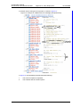
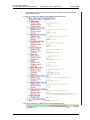
9. Administration .................................................................................................. 70
9.1 Admin Menu Tree ........................................................................................ 70
9.2 Quick Access to the Handset’s Device Information ..................................... 71
9.3 LED indications............................................................................................ 71
10. Troubleshooting.............................................................................................. 72
10.1 Fault Symptoms......................................................................................... 72
10.2 Display Information.................................................................................... 74
10.3 Troubleshooting from the handset Internal Web Administration Page ...... 77
11. Related Documents ....................................................................................... 78
12. Document History........................................................................................... 79
Appendix A: Working with Templates ................................................................ 82
A.1 Create a Template ...................................................................................... 82
13 December 2013 /Ver B
Configuration Manual
WL3 and WL3 Plus WLAN Handset
TD 92930EN
A.2 Export a Template....................................................................................... 82
A.3 Import a Parameter File .............................................................................. 82
A.4 Import a Template ....................................................................................... 83
Appendix B: Programming Custom Sound........................................................ 84
B.1 .Customize the default handset beeps........................................................ 85
Appendix C: Easy Deployment............................................................................ 87
C.1 Prerequisites ............................................................................................... 87
C.2 WLAN discovery ......................................................................................... 88
C.3 WSG server discovery ................................................................................ 89
C.3.1 Server discovery using the DHCP Option 43...................................... 89
C.3.2 Server discovery using the Ascom Service Discovery Protocol (ASDP) ..
89
C.4 Parameter download................................................................................... 90
C.5 Using Easy Deployment together with Client Certificate Distribution.......... 91
C.5.1 The Ascom Service Discovery Protocol (ASDP) Explained................ 91
C.5.2 DHCP Vendor Options Explained ....................................................... 91
C.5.3 Configuration Example of a Linux Server using DHCP Option 43 ...... 96
C.5.4 Configuration Example of an MS Windows 2003 Server using DHCP Option 43..................................................................................................... 96
C.5.5 Configuration of Option 60 and 43 using the standard DHCP vendor class
97
C.5.6 Advanced Configuration of Option 60 and 43 using a new vendor class..
98
C.5.7 Easy Deployment and VLAN ............................................................ 100
C.5.8 Easy Deployment and Certificates.................................................... 101
C.5.9 Troubleshooting Easy Deployment in an MS 2003/2008 DHCP Server ...
102
Index ................................................................................................................... 103
13 December 2013 /Ver B
Configuration Manual
WL3 and WL3 Plus WLAN Handset
1.
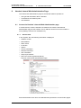
1. Introduction
TD 92930EN
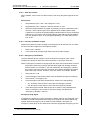
Introduction
This document is a guide for installing, configuring, and maintaining the functionality of
the WLAN Handset.
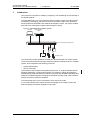
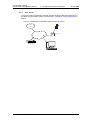
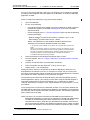
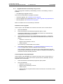
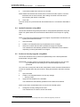
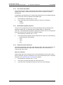
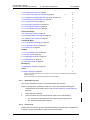
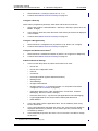
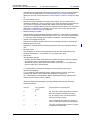
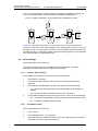
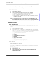
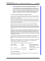
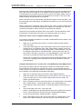
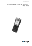
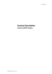
The OpenStage WL3 Voice over Wireless Fidelity (VoWiFi) system provides wireless
IP-telephony, messaging, and alarm functions to enterprise LANs. Using third-party
WLAN products and hardware and software developed in-house, the system enables
data and voice transmission together with seamless roaming.
Figure 1. OpenStage WL3 VoWiFi System
WinPDM
Device Manager
in WSG
Switch to IP Backbone/LAN/Internet
AP
AP
IP-PBX
OpenStage WL3
This document provides guidelines to install the WLAN Handset in a VoWiFi system.
The document describes the settings needed to make the handset function in a VoWiFi
system, and is targeted at the following personnel:
• System Administrator
• Service Technician
The handset is first configured using Easy Deployment, or using the Portable Device
Manager (WinPDM). In small systems where it is possible to collect all handsets to
update settings, daily maintenance is also done by using the WinPDM.OpenStage WL3
WSG Server (WSG) supports managing the handsets centrally using a web interface,
without the need to collect the handsets.
The handset behavior can be customized to suite each user profile.
It is recommended that the reader has basic knowledge of the VoWiFi system and
basic knowledge of handset registration in the PBX.
13 December 2013 /Ver B
1
Configuration Manual
WL3 and WL3 Plus WLAN Handset
1.1
1. Introduction
TD 92930EN
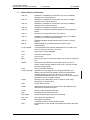
Abbreviations and Glossary
802.11a
IEEE 802.11 standard for transmission rate of up to 54Mbps,
operates in the 5GHz spectrum.
802.11b
IEEE 802.11 standard for transmission rate of up to 11Mbps,
operates in the 2.4GHz spectrum.
802.11g
IEEE 802.11 standard for transmission rate of up to 54Mbps,
operates in the 2.4GHz spectrum.
802.11d
IEEE 802.11 standard for regulatory domains.
802.11e
IEEE 802.11 standard that defines Quality of Service (QoS) for
WLAN.
802.11i
Standard for security improvements for 802.11.
802.11n
IEEE 802.11 standard for transmission rate of up to 100 Mbps,
operates in the 2.4GHz and 5GHz bands.
802.1D
IEEE MAC Bridges standard (interworking for 802.11 among
others).
802.1X
IEEE standard for port-based Network Access Control
(authentication).
Ad-hoc WLAN
A WLAN between two wireless capable devices (normally PCs),
where no Access Point (AP) is involved.
AES
Advanced Encryption Standard.
ALS
Acoustic Location Signal
AP
Access Point
BSS
Basic Service Set. A WLAN with at least one AP that is configured
for it.
BSSID
Basic Service Set Identifier. Hard-coded name of an ad-hoc
WLAN, usually the MAC address of the radio. One type of SSID
(the other being ESSID).
CCX
Cisco Compatible eXtension
Device Manager
Application for managing devices, editing parameters, and
updating devices with new software, without an administrator
manually needing to collect the devices, as it is done by
Centralized Management over the air (OTA). The Device Manager
application runs on an WSG hardware.
DHCP
Dynamic Host Configuration Protocol. Used to send config
parameters to TCP/IP clients.
DNS
Domain Name System
DSCP
Differentiated Services Code Point. QoS on the Network Layer.
Used both for WLANS and LANs.
DTIM
Delivery Traffic Indication Message
EAP
Extensible Authentication Protocol.
EAP-FAST
Flexible Authentication using secure tunneling.
EAP-TLS
EAP-Transport Layer Security.
ELISE
Embedded LInux SErver:
A hardware platform used for WSG modules
ESS
Extended Service Set. WLAN with multiple APs sharing the same
SSID.
13 December 2013 /Ver B
2
Configuration Manual
WL3 and WL3 Plus WLAN Handset
1. Introduction
TD 92930EN
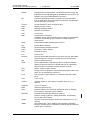
ESSID
Extended Service Set Identifier. The identifying name of a WLAN.
It identifies an AP and distinguishes WLANS from one another. An
ESSID is one type of SSID (BSSID is the other).
IM
Interactive Messaging makes it possible to access information
from an application, and controlling the information, by selecting a
choice received in a message.
License
An authorization to use a licensed function.
MAC
Medium Access Control.
MWI
Message Waiting Indication
NTP
Network Time Protocol
OTA
Over The Air
PBX
Private Branch Exchange:
Telephone system within an enterprise that switches calls between
local lines, and allows all users to share a certain number of
external lines.
PEAP
Protected Extensible Authentication Protocol.
PRI
Primary Rate Interfaces
RSSI
Received Signal Strength Indication.
RTLS
Real-Time Location System
RTS
Request-To-Send.
PTT
Push-To-Talk
Services
Services are predefined functions such as Phone Call, Send Data,
Send Message etc. that are accessible from the Service menu.
SIP
Session Initiation Protocol
SSID
Service Set Identifier. User friendly name of a WLAN. Identifier
attached to packets sent over a WLAN that acts as a password.
Daily used term for ESSID in an ESS wireless topology.
STA
Station. Client in a WiFi network.
QoS
Quality of Service: Defines to what extent transmission rates, error
rates, etc. are guaranteed in advance.
UP 6
User Presence (value between 0-7). Wireless QoS at the MAC
Layer.
VoIP
Voice over IP.
VoWiFi
Wireless version of VoIP. Refers to an IEEE 802.11a, b, g, n
network.
VoWLAN
Voice over WLAN.
WEP
Wired Equivalent Privacy.
Wi-Fi
Wireless Fidelity. The commonly understood name for wireless
LAN networks. Originator is Wi-Fi Alliance.
WinPDM
Portable Device Manager (Windows version):
Used for managing devices, editing parameters, and updating
devices with new software.
WLAN
Wireless Local Area Network. Refers to an IEEE 802.11a, b, g, n
network.
WMM
Wi-Fi Multimedia. A Wi-Fi Alliance interoperability certification,
based on the IEEE 802.11e standard. Provides basic QoS features
to IEEE 802.11 networks.
13 December 2013 /Ver B
3
Configuration Manual
WL3 and WL3 Plus WLAN Handset
1.2
1. Introduction
TD 92930EN
WPA/WPA2
Wi-Fi Protected Access 2. Security method based on 802.11i
standard for wireless networks (data protection and network
access control).
WSG
OpenStage WL3 Wireless Service Gateway:
Module that enables wireless services to and from the handsets in
a WLAN system. It also includes the Device Manager.
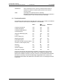
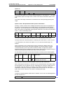
Functionality matrix
The following matrix shows the functionality that currently can be used by the different
versions. These functions require configuration in the WinPDM.
WL3
WL3
Messenger
WL3 Plus
Company Phonebook
Yes
Yes
Yes
Central Phonebook
Yes
Yes
Yes
Centralized Management
Yes
Yes
Yes
Customized GUI
Yes
Yes
Yes
Interactive Messaging (IM)
No
Yes
Yes
Location
No
No
Yes
Push to Talk (PTT)
No
No
Yes
Multifunction button
Yes
Yes
No
Push Button Alarm
No
No
Yes
Man-down and No-movement alarm
No
No
Yes
Acoustic Location Signal (ALS)
No
No
Yes
Services
No
No
Yes
Voice Mail
Yes
Yes
Yes
Upload Language
Yes
Yes
Yes
Clear lists in charger
Yes
Yes
Yes
The three versions WL3,WL3 Messenger Upgrade, and WL3 Plus use the same
hardware and software (except WL3 Plus, which uses a different hardware), and
features are enabled by licensing. The WL3 version is an unlicensed WLAN Handset
with basic functionality, and the WL3 Messenger UpgradeWL3 Plus versions are
licensed WLANHandsets with additional functionalities such as messaging and alarm,
respectively.
13 December 2013 /Ver B
4
Configuration Manual
WL3 and WL3 Plus WLAN Handset
2.
2. Pre-Installation
TD 92930EN
Pre-Installation
Before installing handsets in a VoWiFi system, ensure that the following equipment is
available:
•
•
•
Set up chargers and charge the handset batteries before installation.
Have a number plan available for the handsets.
Check that the IP addressing plan is set up to support the amount of handsets to be
deployed.
We assume that the VoWiFi system is installed, including some or all of the following
components (depending on system configuration):
•
DHCP Server. A DHCP server allows devices to request and obtain an IP address
from a server that has a list of addresses available for assignment. If the WLAN
does not have access to a DHCP server, a list of static IP addresses is necessary.
• Portable Device Manager. The WinPDM is used for administration and
programming of the handsets. All settings and updates are in this case done using
the DP1 Desktop Programmer cradle connected over USB.
• WSG. The WSG handles all communication between the WLAN and its built-in
Device Manager. Before installing the handset, make sure the WSG IP address is
available.
For effective administration of a VoWiFi system with several handsets, it is required to
have both a WinPDM and a Device Manager included in the WSG. In this case, the
WinPDM is only used to allow the handset to access the WLAN system. All other
settings and updates are done with the Device Manager in the WSG.
2.1
VoWiFi System IP addresses
To configure the handsets, enter the IP addresses in the table below.
Table 1.
Device
IP address/Number/
Port
IP-PBX
If used
WSG
Subnet
Required
If used
Maska
If used
Number plan
N/A
NTP Server address
Yes
b
DNS Server addressa
VoIP settingsc
Yes
Central Phonebook
If used
Syslog server
If used
TFTP server
Ekahau RTLS
If used
d
If used
DHCP range
a. Only required if no DHCP is used, that is, static IP is used.
b. Depending on system configuration
c. Gatekeeper IP address or SIP proxy IP address used to access the PBX.
d. The IP address and port to the location server.
13 December 2013 /Ver B
5
Configuration Manual
WL3 and WL3 Plus WLAN Handset
3.
3. Programming the WLAN Handset
TD 92930EN
Programming the WLAN Handset
This section describes how to configure handsets in the following three different ways:
•
•
By inserting it into a DP1 Desktop Programmer cradle connected using USB to the
WinPDM.
Over-The-Air (OTA) using the Device Manager in the WSG.
NOTE: This requires that the IP address to the WSG has been configured in the
handset. The IP address is configured using WinPDM or using the handset’s
Admin menu.
•
Using the Admin menu, it is possible to configure the basic network settings. See 9.
Administration on page 71 for more information about the settings that can be
configured.
It is recommended to use the Device Manager application in the WSG to configure
handsets in a large system. The Device Manager can install, upgrade, and configure a
large amount of handsets simultaneously. Another benefit is that the collection of the
handsets from users is not needed.
The WinPDM configures one handset at a time. The handset is inserted in the DP1
Desktop Programmer, connected to the administrator’s computer using USB.
TIP: It is recommended to use templates when configuring handsets. By using a
template, the same configuration can easily be applied to many handsets
simultaneously.
3.1
WinPDM
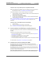
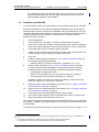
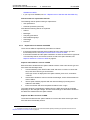
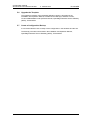
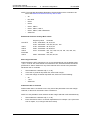
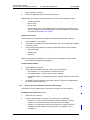
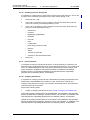
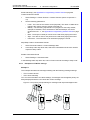
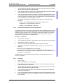
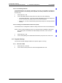
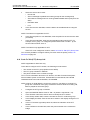
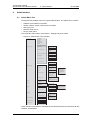
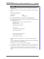
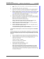
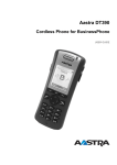
The WinPDM runs on a PC and is used to configure the handset as follows:
•
Connect a DP1 Desktop Programmer cradle through a USB port, to the computer
running WinPDM.
• Start WinPDM.
• Place the handset in this cradle connected to WinPDM.
For instructions on how to install and use the WinPDM, see Installation and Operation
Manual, Portable Device Manager, Windows version, TD 92712EN.
Figure 2. Configuration of handsets using WinPDM
PDM
Win
3.2
WSG
WSG runs on an ELISE3 module.
For instructions on how to use the WSG, see Installation and Operation Manual,
OpenStage Wireless Service Gateway (WSG), TD 92442EN.
13 December 2013 /Ver B
6
Configuration Manual
WL3 and WL3 Plus WLAN Handset
3.2.1
3. Programming the WLAN Handset
TD 92930EN
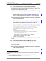
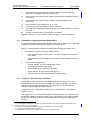
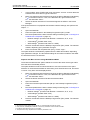
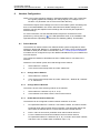
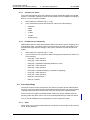
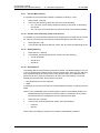
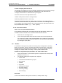
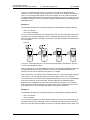
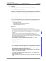
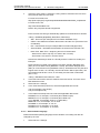
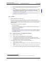
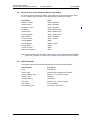
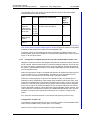
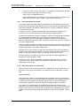
Over-the-Air
There is no external equipment required, besides the Device Manager application in
the WSG and the VoWiFi system. Proceed with 4. Installation of WLAN Handsets on
page 8.
Figure 3. Configuration of handsets using Over-the-Air (OTA)
VoWiFi
System
IP
Device Manager
in WSG
13 December 2013 /Ver B
AP
Access Point
Client
7
Configuration Manual
WL3 and WL3 Plus WLAN Handset
4.
4. Installation of WLAN Handsets
TD 92930EN
Installation of WLAN Handsets
This section describes the recommended procedure to install and configure handsets.
There are several ways to install a handset but the procedures described here ensures
minimal effort for the administrator.
There are two ways of configuring the handsets:
•
•
Local management
Centralized management (Over-the-air (OTA))
Local management of handsets
NOTE: In larger installations local management is not recommended, since it requires
physical access to all handsets.
Either the keypad on the handset, or the WinPDM is used to configure the handsets. It
is only recommended to use the keypad, if a quick change of a parameter value is
needed, for example, in a lab environment, or in a test installation. It is tedious to enter
all parameters using the keypad. Access from the keypad is only available to a limited
set of parameters, and to get access to all parameters, the WinPDM must be used.
The WinPDM is aimed for smaller sites where the handsets are near to hand. One
handset at a time is configured, when inserted in a Desktop Programmer (DP1)
connected to the administrators computer over USB. See Installation steps in small
VoWiFi Systems using WinPDM on page 9.Centralized management of handsets
NOTE: This is also referred to as Over-The-Air (OTA) management, where parameters
changes are updated over the WLAN.
A WLAN connection and the Device Manager application (WSG) is used to configure
the handsets.
Prerequisites for Centralized management are as follows:
•
•
The handset has a functional WLAN association.
WLAN parameters are set correctly, to be able to connect to the Messaging
system.The handset has the correct settings to access the Device Manager
application as follows: - A configured number to be used as identity to login to the
Messaging system.
- The IP address of the Messaging system.
The WLAN and Messaging parameters are set manually, using the keypad or the
WinPDM. Then the handset logs into the Messaging system, and downloads the
intended handset profile, which contains all other needed parameters for a site.
See 4.2 Installation with Central Device Management (WSG) on page 9.
It is recommended to use the Easy Deployment process, where the needed WLAN
parameters and the Messaging system information is distributed automatically to the
handset, using a DHCP server (and optionally the Ascom Service Discovery Protocol).
See Appendix C: Easy Deployment on page 89.
NOTE: If the WLAN system uses a 802.1x security protocol that requires certificates for
authentication/encryption to the WLAN, the certificates must be prepared and stored
individually in the Device Manager for each number, before starting the Easy
Deployment process, see 4.2 Installation with Central Device Management (WSG) on
page 9.
See 4.1 Handset Installation in the WLAN System using Easy Deployment on page 9
13 December 2013 /Ver B
8
Configuration Manual
WL3 and WL3 Plus WLAN Handset
4. Installation of WLAN Handsets
TD 92930EN
Installation steps in large VoWiFi Systems using WSG and WinPDM
NOTE: If the handset to be installed must use a certificate to access a WLAN, follow
the instructions in section 4.3 Installation with WinPDM on page 13.
These WLAN settings are common network settings for all handsets.
1
Create templates in the Device Manager in WSG, one with network settings and
another with common settings.
2
Create Numbers and apply the templates.
3
Use either the Easy Deployment procedure, or create a template with identical
network settings in the WinPDM.
See 4.1 Handset Installation in the WLAN System using Easy Deployment on page 9 or
4.2 Installation with Central Device Management (WSG) on page 9 for more
information.
Installation steps in small VoWiFi Systems using WinPDM
1
Create Numbers.
2
Create one template for all settings in the WinPDM.
See 4.3 Installation with WinPDM on page 13 for more information.
4.1
Handset Installation in the WLAN System using Easy Deployment
With the Easy Deployment procedure, handsets are installed without the need for the
WinPDM.
Handsets are automatically installed if the following is fulfilled:
•
•
•
•
The LAN and WLAN system is configured for Easy Deployment, see Appendix C:
Easy Deployment on page 89.
The handset is not associated to any network (SSID)
The handset software is version 5.1.18 or higher
The Call ID (endpoint number), that is, the phone number of the handset is decided
For further details, see Appendix C: Easy Deployment on page 89.
4.2
Installation with Central Device Management (WSG)
Easy Deployment is the recommended procedure of using the Central Device
Management (WSG) for deployment, as the WLAN and Messaging parameters now
are configured without the WinPDM.
Easy Deployment uses, in most parts, the same procedure, as the standard Central
Device Management (WSG) procedure. Special notes marked “(ED)” show where the
procedure is unique for Easy Deployment.
NOTE (ED): With Easy Deployment, it is very important that the building of the number
plan and the parameters are correct, since the aim is to avoid using the WinPDM.
13 December 2013 /Ver B
9
Configuration Manual
WL3 and WL3 Plus WLAN Handset
4.2.1
4. Installation of WLAN Handsets
TD 92930EN
Create a Network Template in the Device Manager in the WSG
Create one template that contains the network parameters (also include the security
settings). Besides the network parameters, additional parameters can also be set, for
example VoIP settings and IP address to WSG.
The template must be created, and applied, to prevent the WSG from restoring
the parameters to default during the first synchronization.
NOTE: (ED): If using Easy Deployment, the IP-address to the Device manager in the
template, can either be set, or left blank, in which case the server discovery
process is used at every startup, see C.3 WSG server discovery on page 91.
NOTE: Only select the parameters that are modified, if all parameters are selected, the
system performance decreases.
1
Open a web browser and enter the IP address or NetBIOS name to the WSG.
TIP: Be sure to configure all needed parameters for 802.1x security, but installing
Server and/or Client Certificate can not be done using a template. This must be
done individually on each Number, see Client certificate on page 103.
2
Click “Device Manager“. You might be prompted to log on the Device Manager.
3
Select the Templates tab and click “New“. The New template window is opened.
4
In the Device type and Parameter version drop-down lists, select the
corresponding device type and parameter version to use, respectively.
5
In the Name field, enter a descriptive name for the template.
6
Click “OK“.
7
Set the following network parameters:
8
•
Network settings1 (located under Network > Network A, B, C, or D)
•
VoIP settings2 (located under VoIP)
•
Syslog settings3 (if any) (located under Device > General)
•
WSG settings4 (located under Device > WSG)
Click “OK“ to save the template.
TIP: See Appendix A for tip on how to work with templates when using both WinPDM
and WSG.
4.2.2
Create a Common Template in the Device Manager in the WSG
Create another template with the common handset settings applicable to all handsets
(exclude the parameters and security settings configured in the Network template).
This template contains for example, hidden menu items in the display, certain level of
ring signals and vibrators.
NOTE: Only select the parameters that are modified, if all parameters are selected, the
system performance decreases.
1
Open a web browser and enter the IP address or NetBIOS name to the WSG.
2
Click “Device Manager“.
1. All required system settings for the WLAN. For example SSID and Security mode. If using a security mode that
requires certificates, also use an NTP server, to assure the correct time in the handset, as certificates only are valid within
a certain time.
2. For example VoIP protocol, Gatekeeper IP address or SIP proxy IP address used to access the PBX.
3. The parameter “Syslog“ must be enabled in order to set the “Syslog IP address“.
4. IP address and password (if any) to the WSG.
13 December 2013 /Ver B
10
Configuration Manual
WL3 and WL3 Plus WLAN Handset
4. Installation of WLAN Handsets
TD 92930EN
3
Select the Templates tab and click “New“.
4
In the Device Type and Parameter version drop-down lists, select the
corresponding device type and parameter version to use, respectively.
5
In the Name field, enter a descriptive name for the template.
6
Set the specific parameters. See section 4.5 Configure a Handset with a
Template on page 14 for more information.
4.2.3
Create Numbers in the WSG
Create a range of Numbers and apply the templates previously created in the WSG.
IMPORTANT: Do not add numbers for handsets that are already configured and
functional, because these handsets already exist in the system, though
they are not saved in the Device Manager application in WSG. The Device
Manager application overwrites the existing parameters in the handset.
NOTE: The parameter version of the template must be equal to or less than the
selected parameter version.
1
Open a web browser and enter the address to the WSG.
2
Click “Device Manager“.
3
Select the Numbers tab and click “New“. The New numbers window is opened.
4
In the Device Type and Parameter version drop-down lists, select the device
type and the parameter version to use, respectively.
NOTE: The device type and parameter version must match the handsets to be used to
apply the template.
5
In the Prefix field, enter the numbers’ prefix (if needed).
6
Create a range of numbers by selecting the “Range“ option. Enter the start call
number and the end call number in the fields, respectively. Click “OK”.
NOTE: The maximum range that can be added at a time are 100 numbers.
7
Apply the network settings template to the selected handsets. See 4.5.2 Apply a
Template to a Handset with a Number on page 15.
8
Apply the common settings template to the selected handsets. See 4.5.2 Apply a
Template to a Handset with a Number on page 15.
NOTE (ED): If the 802.1x security protocol with EAP-TLS or EAP-PEAP/
MSCHAPv2 is used, also include the server certificate, select which Client
certificate to use. The Client certificates must be installed first by editing each
Number. Client certificates cannot be distributed using a template, as they are
individual.
9
4.2.4
Close the WSG.
Create a Network Template with Initial Configuration in the WinPDM
In a factory delivered handset, the WLAN settings are not configured as required to
access the WSG. Using the WinPDM allows the handset to be primed with the WLAN
parameters and allows the handset to log in to the Device Manager in WSG for future
management over the air.
Create a template with the basic network settings and IP address to WSG. This
template is only used once for each handset because it must access the WLAN and
13 December 2013 /Ver B
11
Configuration Manual
WL3 and WL3 Plus WLAN Handset
4. Installation of WLAN Handsets
TD 92930EN
then log on the Device Manager. After log in, the settings in the handset are changed
according to the templates, that were applied to the Numbers, in the Device Manager
application in WSG.
NOTE: If using Easy Deployment, only perform step 6) below.
1
Open the WinPDM.
2
Do one of the following:
•
If a network template was created in the Device Manager in WSG, export this
template and import it to WinPDM. See Appendix A for more information.
(Recommended)
•
Create a template (see 4.5.1 Create a template on page 15) with the following
network parameters:
- Network settingsa (located under Network > Network A (B, C, or D)
- WSG settingsb (located under Device > WSG)
NOTE: The parameters in this template should be identical to the
parameters in the network template created in the WSG.
a. All required system settings for the WLAN. For example SSID and Security
mode.
NOTE: If the production system is using 802.1x security, this method is not the
best option, since the certificates must be manually installed in the handset before
they login for the first time (before step 6). The Easy Deployment process overcomes this problem by using a staging WLAN, which does not use 802.1x.
b. IP address and password (if any) to WSG.
3
Place the handset in the Desktop Programmer (DP1) cradle.
4
Run the template. See 4.5.3 .Apply a Template to a Handset without a Number
on page 15.
5
Remove the handset when synchronization is finished.
6
Enter the Number and the password 1 (if any). Press “Login“.
7
Repeat step 3 – 6 for all handsets.
Settings that were stored for the handset in the Device Manager in WSG are now
downloaded to the handset. This can, for example, be unique soft- or hot keys that
have been prepared earlier. When the settings have been downloaded to the handset,
the handset can restart, depending on the parameter changes.
The handset synchronizes with the WSG at startup, and also immediately after any
handset parameter change. (The change is done either using the handset keypad, or
when editing parameters in the Device Manager in the ). Depending on what is
changed, and where the change is done, the parameters are synchronized to, or from,
the handset.
Those changes are not stored in the WinPDM, as there is no connection between the
WinPDM and the WSG Device Management database. The database in the WinPDM
synchronizes with the handset, when the handset is placed in the Desktop Programmer
(DP1) cradle (online via USB).
NOTE: As there is no connection between the WinPDM and the WSG Device
Management databases, except over the handset, the WLAN and WSG settings
can differ in the WinPDM and the WSG. Parameters can inadvertently be
reverted with old values, when first, the WinPDM synchronization process runs,
(when the handset is placed in the Desktop Programmer (DP1) cradle), and after
that, (when the handset is removed from the Desktop Programmer (DP1) cradle),
1. The password is only required if the “Password“ parameter is set.
13 December 2013 /Ver B
12
Configuration Manual
WL3 and WL3 Plus WLAN Handset
4. Installation of WLAN Handsets
TD 92930EN
the handset goes online with the Messaging system, and the synchronization
process with the WSG runs, and vice versa. The solution for this, is to avoid
storing handset numbers in the WinPDM.
4.3
Installation with WinPDM
In a small VoWiFi system, the administration can be handled using only the WinPDM.
The synchronization is in this case not handled automatically by the system when a
handset’s parameters are changed in the WinPDM. When the parameters have been
changed in WinPDM, each handset must be placed in the Desktop Programmer (DP1)
cradle connected to the administrator’s computer in order to synchronize the
parameters with the handset.
1
Open the WinPDM.
2
In the Numbers tab, click “New“. The New numbers window is opened.
3
In the Device Type and Parameter version drop-down lists, select the matching
device type and the parameter version for the handset to be used, respectively.
4
In the Prefix field, enter the numbers’ prefix (if needed).
5
Create a range of numbers by selecting the “Range“ option. Enter the start call
number and the end call number in the fields, respectively.
6
Click “OK”.
7
Create a network settings template (see 4.5.1 Create a template on page 15)
with the following network parameters:
•
8
Network settings1 (located under Network > Network A, B, C, or D)
Create another template (see 4.5.1 Create a template on page 15) with the
common handset settings applicable to all handsets (exclude the network
parameters and used security settings). Example of parameters settings:
•
VoIP settings2 (located under VoIP)
•
Software TFTP IP address (if any) (located under Device > General)
•
Syslog settings3 (if any) (located under Device > General)
In addition, settings for hiding menu items in the display, certain level of ring
signal and vibrators etc. can also be configured.
9
Apply the network settings template to the handset, see 4.5.2 Apply a Template
to a Handset with a Number on page 15.
10
Apply the common settings template to the handset, see 4.5.2 Apply a Template
to a Handset with a Number on page 15.
11
Place the handset in the Desktop Programmer (DP1) cradle.
12
In the Device Wizard window, select “Associate with number“ and press “OK“.
13
Select the handset to associate with. Press “OK“.
The number and parameter settings saved in the WinPDM are now synchronized with
the handset. In addition, the handset’s Device ID is also synchronized with the number
in the WinPDM.
If certificates must be used to access a VoWiFi system, also perform the steps 14 - 19.
1. All required system settings for the WLAN. For example SSID and Security mode, and if used, any certificates for
802.11x.
2. VoIP protocol, Gatekeeper IP address or SIP proxy IP address used to access the PBX.
3. The parameter “Syslog“ must be enabled in order to set the “Syslog IP address“.
13 December 2013 /Ver B
13
Configuration Manual
WL3 and WL3 Plus WLAN Handset
4. Installation of WLAN Handsets
TD 92930EN
14
In the Numbers tab, right-click the handset’s number and select “Manage
certificates“. A Manage certificate window opens.
15
In the Root tab and Client tab, click “Browse“ and select the certificates to import.
Click “Close“.
16
In the Numbers tab, right-click the handset’s number and select “Edit
parameters“.
17
Select “Network X“ (X represents A, B, C, or D).
18
In the Security mode drop-down list, select “EAP-TLS“.
19
In the EAP client certificate drop-down list, select the client certificate to be used.
Click “OK“.
20
Remove the handset when synchronization is finished.
Repeat the steps 11-13, 20 (if needed, perform the steps 14-19) for all handsets.
4.4
Installation using the Handset’s Admin Menu
It is possible to install a handset using its Admin menu. This is useful when no WinPDM
or WSG is available and the handset needs to be installed quickly.
NOTE: It is only possible to configure the basic settings through the Admin menu.
1
2
4.5
There are two options to access the Admin menu:
•
If the handset has been factory reset or not been configured; in idle mode,
enter 40022.
•
If the handset has been configured; press “Menu“, select “Settings“ and enter
40022.
Set the following parameters:
•
Network settings1 (located under Network setup)
•
VoIP settings2 (located under VoIP)
•
WSG settings3 (if any) (located under WSG)
•
Syslog settings4 (if any) (located under Syslog)
•
Add license key (if any) (located under Enter license key)
Configure a Handset with a Template
It is possible to select a handset in the WinPDM and directly change one or more
configuration parameters. By using a template, the same configuration can easily be
applied to many handsets simultaneously. Templates are also an efficient way to
control the changes applied to each handset.
Templates enables configuration of all aspects of a handset from sound volume to
keypad shortcuts.
Your supplier can provide example templates for different PBX:s. The handset has full
functionality towards the PBX even without such a template. By using such a template,
though, the handset is customized for that PBX with menu options for PBX specific
functions.
1. All required system settings for the WLAN. For example SSID and Security mode. Note that the certificates cannot
be entered, nor referred to, using the keypad.
2. VoIP protocol, Gatekeeper IP address or SIP proxy IP address used to access the PBX.
3. IP address and password (if any) to the WSG.
4. The parameter “Syslog“ must be enabled in order to set the “Syslog IP address“.
13 December 2013 /Ver B
14
Configuration Manual
WL3 and WL3 Plus WLAN Handset
4.5.1
4. Installation of WLAN Handsets
TD 92930EN
Create a template
1
Open the WinPDM or the Device Manager in the WSG.
2
Select the Templates tab and open the menu “Template > New...“. The New
Template window is opened.
3
Select the device type and parameter version that matches the software version
installed on the handset. Give the template a descriptive name.
The parameters that are not part of the template are left unchanged on the handset.
The parameter version of an installed handset is visible under the Numbers tab or the
Devices tab.
4
Click “OK“.
5
Select the check box of each parameter that you want to be part of this template
and enter the proper value.
6
Click “OK“ to save the template.
4.5.2
Apply a Template to a Handset with a Number
1
Open the WinPDM or the Device Manager in the WSG.
2
In the Numbers tab, select the handset(s) you want to apply the template to.
NOTE: If several handsets are selected, they must be of the same device type and
have the same parameter version.
3
Right-click and select “Run template...“.
Only templates with a parameters version matching the selected handsets are shown.
Select the template you want to apply and click “OK“.
The template is applied. The number of parameters in the template affects the time it
takes to apply the template to the selected handsets.
When looking at a handset under the Numbers tab, the column “Last run template“
shows the name of the most recently applied template.
4.5.3
.Apply a Template to a Handset without a Number
This feature is only applicable for the WinPDM. It is possible to apply a template to a
handset without a number in the WinPDM.
1
Place the handset in the Desktop Programmer (DP1) cradle.
2
In the Found Device Wizard window, select the “Run template“ option.
3
Click “Next >“.
Only templates with a parameter version matching the selected handset are shown.
4
Select the desired template and click “OK“.
The template is applied. The number of parameters in the template affects the time it
takes to apply the template to the selected handset.
4.5.4
Save Handset Configuration as a Template
It is possible to save all settings of a handset as template. Note that this does not
include contacts, certificates and other personal data. The template will only contain
configuration data.
This template can be used as a backup if you want to restore the configuration of the
handset at a later stage or as a template that can be applied to a number of handsets.
13 December 2013 /Ver B
15
Configuration Manual
WL3 and WL3 Plus WLAN Handset
4. Installation of WLAN Handsets
TD 92930EN
1
Open WinPDM or the Device Manager in the WSG.
2
In the Numbers tab, select the handset you want to save as a template.
3
Make a right-click and select “Use as a template...“. Enter a descriptive name for
the template.
4
The Edit template window is opened. By default, all parameters are selected and
are saved when clicking “OK“.
If one or more parameters should be excluded, remove them by clearing the
check box next to the parameter.
Some parameters are user specific. If it is decided to apply this type of template
to several handsets, it is recommended to exclude the following parameters:
5
4.5.5
•
User display text - A text string displayed in idle mode. The parameter is
located directly under “Settings“.
•
Phone lock PIN code - The security code used to unlock the keypad. The
parameter is located under Settings > Locks.
•
Endpoint ID - The identity/name of the user registered in the PBX. The
parameter is located under VoIP > General.
Click “OK“.
Synchronizing a Handset with WinPDM
After installing and saving a handset, it is synchronized each time it is connected to the
WinPDM. The synchronization transfers parameter changes between the handset and
the WinPDM and vice versa as follows:
•
If a parameter has been changed in the handset, it is transferred to the
WinPDMWSG.
• If a parameter has been changed in the WinPDMWSG while the handset was
disconnected, it is transferred to the handset.
If the same parameter has been changed in both the WinPDMWSG and the handset,
the value in WinPDMWSG will be transferred to the handset.
4.5.6
Configure Handset without Saving It in WinPDM
It is possible to configure a handset without saving it in the WinPDM. An unsaved
handset does not have the symbol
in the Saved column. The settings in the handset
can be synchronized and saved in the WinPDM later on. However, it is recommended
to save the handset in WinPDM, if backup is required. For example when a handset
needs to be replaced.
1
Place the handset in the Desktop Programmer (DP1) cradle.
2
Open WinPDM.
3
In the Numbers tab, select the unsaved handset you want to configure.
4
Select Number > Edit parameters.
5
The Edit parameters window is opened. Edit the parameters of the handset and
click “OK“.
6
Remove the handset from the Desktop Programmer (DP1) cradle. The handset
is no longer visible in the WinPDM and the settings are only saved in the
handset.
13 December 2013 /Ver B
16
Configuration Manual
WL3 and WL3 Plus WLAN Handset
5.
5. Maintenance
TD 92930EN
Maintenance
5.1
Handset
In an existing VoWiFi system, it is important to be able to replace handsets, install new
handsets, and exchange faulty handsets. The recommended procedure is to use a
template with basic network settings for log in, created in the WinPDM, and then import
the rest of the settings that were created by the templates in Device Manager in WSG
It is also important to be able to upgrade system parameters and security settings in
the handsets. These upgrades are preferably done in the WSG, if available.
If you use WinPDM and WSG, do one of the following:
•
If you want to install new handset, see 4.2 Installation with Central Device
Management (WSG) on page 9.
• If you want to create spare handsets to be used when broken handsets need to be
replaced later on, see 5.1.1 Configure Spare Handsets without a Number in Large
Systems.
If only WinPDM is used, do one of the following:
•
•
5.1.1
If you want to install new handset, see 4.3 Installation with WinPDM on page 13.
If you want to replace a broken handset, see 5.2.4 Replacement of Handset with
WinPDM Only on page 26.
Configure Spare Handsets without a Number in Large Systems
In large systems where WSG is used, it is recommended to configure a few spare
handsets without a number to quickly replace a broken handset later on.
Create a Template
1
Open WinPDM.
2
Select the Templates tab and click “New“. The New template window is opened.
3
In the Device type and Parameter version drop-down lists, select the matching
device type and parameter version respectively, for the spare handset to use.
4
In the Name field, enter a descriptive name of the template.
5
Click “OK“.
6
Set the following network parameters:
7
•
Network settings1 (located under Network > Network A, B, C, or D)
•
VoIP settings2 (located under VoIP)
•
Syslog settings3 (if any) (located under Device > General)
•
WSG settings4 (if any) (located under Device > WSG)
Click “OK“ to save the template.
Apply Template to a Handset without a Number
1
Place the handset in the Desktop Programmer (DP1) cradle.
2
In the Found Device Wizard window, select the “Run template“ option.
1. All required system settings for the WLAN. For example SSID and Security mode.
2. For example VoIP protocol, Gatekeeper IP address or SIP proxy IP address used to access the PBX.
3. The parameter “Syslog“ must be enabled in order to set the “Syslog IP address“.
4. IP address and password (if any) to the WSG.
13 December 2013 /Ver B
17
Configuration Manual
WL3 and WL3 Plus WLAN Handset
3
5. Maintenance
TD 92930EN
Click “Next >“.
Only templates with a parameter version matching the selected handset are shown.
4
Select the desired template and click “OK“.
The template is applied. The number of parameters in the template affects the time it
takes to apply the template to the selected handset.
5
Switch off the handset when User name and Password are displayed.
TIP: If the handset replaces a broken handset, continue with 5.2.2 Replacement of
Handset with WSG on page 23.
5.1.2
Upgrade Handset Software
NOTE: Read the software Release Notes before changing the software.
The handset software can be upgraded over the air using Centralized Device
Management (WSG) or a TFTP server, or by cable using WinPDM.
Upgrade Handset Parameter
A parameter upgrade can restart the handset, for example, when upgrading the NTP
server. The text “Remotely updated” is shown in the handset display when the handset
restarts after an upgrade.
5.1.3
Upgrade Software OTA using TFTP
If no WSG is available, it is recommended to use software upgrade OTA using TFTP,
which is used in small VoWifi systems.
The benefit is that the handsets do not need to be collected by the administrator since
the software upgrade is performed over the air.
To upgrade the software using TFTP, perform the following:
1
If needed, configure the handset in WinPDM to access a TFTP server, see
Configure Access to the TFTP Server.
TIP: It is recommended to configure the TFTP server’s IP address when
installing the handsets. See 4.3 Installation with WinPDM on page 13.
2
If needed, upload a new software information file (packageinfo.inf) and a
software (.bin) file to the TFTP server. These files are provided by your supplier.
First rename the .pkg file to .zip and then unzip the files. Then the needed .inf
and .bin files are available.
See the manual for the TFTP server used, for more information on how to upload
files.
3
Restart the handset. After the handset restarts, it connects to the TFTP server
and downloads the software information file (.inf) that contains information about
the software version. If the software version differs from the handset’s software
version, the handset downloads the software file (.bin) from the TFTP server.
The handset restarts when the software upgrade is performed.
Configure Access to the TFTP Server
1
Place the handset in the Desktop Programmer (DP1) cradle.
2
Open the WinPDM.
3
Open the Numbers tab and select the handset.
4
Right-click and click “Edit parameters“.
13 December 2013 /Ver B
18
Configuration Manual
WL3 and WL3 Plus WLAN Handset
5. Maintenance
TD 92930EN
5
Select Device > General.
6
In the Software TFTP IP address field, enter the IP address to the TFTP server.
7
Click “OK“.
5.1.4
Upgrade Software using WinPDM
Software upgrade using WinPDM is performed in small VoWiFi systems. The handsets
need to be collected by the administrator because the software is upgraded using the
connected to WinPDM.
1
Open the WinPDM.
2
In the Devices tab, right-click the handset to be upgraded. Select “Upgrade
software...“.
3
In the Available files drop-down list, select the desired software file (.bin).
If needed, import the software file to be used by clicking “Import“. Locate the
software file (.bin or .pkg) and click “Open“.
4
5.1.5
Click “OK“. The dialog window “Shutting down” followed by “Remotely updated”
is shown in the handset display.
Upgrade Software Over the Air (OTA) through Centralized Device
Management (WSG)
Software upgrade using WSG is performed in large VoWiFi systems. The benefit is that
the handsets do not need to be collected by the administrator because the software
upgrade is performed over the air (OTA).
1
Open the Device Manager in the WSG.
2
Open the Devices tab and select the handsets to be upgraded.
3
Right-click and click “Upgrade software...”.
4
In the Available software drop-down list, select the desired software file (.bin).
If needed, import the software file to be used by clicking “Import“. Locate the
software file (.bin or .pkg) and click “Open“.
5
In the Upgrade section and Activate new software section, select when the
software is upgraded and activated on the handset, respectively.
6
Click “OK“.
TIP: It is also possible to upgrade several handsets of the same device type
simultaneously using the Baseline function in the WSG. See Installation and Operation
Manual, OpenStage Wireless Service Gateway (WSG), TD 92442EN.
5.1.6
Recapture the Earlier Software
The handset stores two software versions which makes it possible to force the handset
to jump back to the earlier software. This feature is used if the current software does
not work properly.
NOTE: The handset must be switched off to be able to load the earlier software.
Press and hold the keys “7” and “8” and press On/Off key at the same time. The
handset loads the earlier software and keeps it, if the handset is not restarted.
13 December 2013 /Ver B
19
Configuration Manual
WL3 and WL3 Plus WLAN Handset
5.1.7
5. Maintenance
TD 92930EN
Upgrade Handset Functionality using License
Users can upgrade a handset by downloading a license. The following license is
available:
• WL3 Messenger Upgrade License
There are three alternatives to upgrade a handset:
•
•
•
Automatic upgrade, see Automatic license upgrade.
License upgrade using import/export, see License upgrade using import/export.
Manual upgrade, see Manual license upgrade.
NOTE: A handset can be re-licensed up to 99 times.
Automatic license upgrade
Use this option if the WinPDM has an internet connection to the License Server.
1
Open the WinPDM.
2
Place the handset in the Desktop Programmer (DP1) cradle.
irst time the handset logs on the WinPDM, the license key is automatically
downloaded to the handset, go to step 4.
3
If the handset is logged on to the WinPDM after the first time, no automatic
check for licenses is done. Synchronize the WinPDM and license server as
follows:
•
Select the “Licences“ tab.
•
Right-click the handset in the list.
•
Select “Refresh“.
The license key is downloaded to the handset.
4
The handset restarts. See also 5.1.7 Upgrade Handset Functionality using
License on page 20 to view the handset’s license option(s).
If the handset is updated to a new device type (to WL3 Messenger Upgrade
License), both the new device and the old device is displayed in WinPDM. The
old device has to be manually removed.
License upgrade using import/export
Use this option if the WinPDM has no internet connection to the License Server. A
product information file (.XML) must first be exported from the WinPDM, and then
imported to the License Web.
1
Place the handset in the Desktop Programmer (DP1)cradle.
2
Open the WinPDM.
•
Select the “Licences“ tab.
•
Right-click the handset(s) in the list.
•
Select “Export“.
•
Save the file on a computer with an internet connection to access the License
Web later on.
13 December 2013 /Ver B
20
Configuration Manual
WL3 and WL3 Plus WLAN Handset
3
5. Maintenance
TD 92930EN
In a web browser, enter the address to the License Web:
“https://www.xxxxxxxxxx“
The License Web is used for;
•
Importing the product information file
•
Viewing/Purchasing the license(s) for the handset(s)
•
Downloading the license file containing the license key(s) for the handset(s)
See the online help on the License Web for information on how to use the
License Web.
4
When the license file (.XML) containing the license key(s) is downloaded from
the License Web, select File > Import > Licences in the WinPDM to import the
file.
5
When the file is imported, the license key(s) is downloaded to the handset(s),
and the handset restarts. See also 5.1.7 Upgrade Handset Functionality using
License on page 20 to view the handset’s license option(s).
If the handset is updated to a new device type (to WL3 Messenger Upgrade
License), both the new device and the old device are displayed in WinPDM. The
old device has to be manually removed.
Manual license upgrade
Use this option if the serial numbers of the handset cannot be exported to a file
because a WinPDM is not in use. The serial number(s) must be manually entered in
the License Web to get the corresponding license key for the handset. The license key
must also be manually entered in the handset. See the online help on the License Web
for information on how to get a license key.
TIP: If several handsets are upgraded, it is recommended to use License upgrade
using import/export on page 20.
The license key is added using the Admin menu in the handset, see 9.1 Admin Menu
Tree on page 71 for information on how to activate the Admin menu.
TIP: It is also possible to press *#35# in idle mode for quick access to the “Enter license
key“ menu.
1
Press the soft key “Menu“.
2
Select “Calls“.
3
Select “Admin menu“.
4
Select “Enter license key“.
5
Enter license key without blanks.
6
Press “OK“.
If the license key is valid, a dialog window “License key accepted“ is shown. The
handset restarts.
If the handset has been updated to a new device type (to WL3 Messenger Upgrade
License), both the new device and the old device are displayed in WinPDM. The old
device has to be manually removed.
Move License
It is possible to move a product license (WL3 Messenger Upgrade License) to an
unlicensed handset. Any optional licenses follow. For example, aWL3 Messenger
Upgrade license can be moved from a handset with a broken display to an unlicensed
handset. The broken handsetcan then be sent for repairs.
13 December 2013 /Ver B
21
Configuration Manual
WL3 and WL3 Plus WLAN Handset
5. Maintenance
TD 92930EN
Prerequisites: A WinPDM that supports the move license function, and a connection to
the license server.
To move a license using the WinPDM:
1
Place the licensed handset in the desktop programmer.
2
On the Licenses tab, select the handset online.
3
On the License menu, click “Move license...”.
4
In the Move license dialog, select the unlicensed handset and click “OK”.
The handset in the desktop programmer is restarted.
5
Place the unlicensed handset in the desktop programmer.
6
On the Licenses tab, select the handset online.
7
On the License menu, click “Refresh”.
The handset in the desktop programmer is restarted.
5.1.8
Perform a Factory reset
When a factory reset is done on a handset, all configuration settings are restored to
default values; PBX subscriptions, contacts, messages, downloaded language,
certificate etc. are removed. The software and licensesare left intact.
Factory Reset using WinPDM or Device Manager (WSG)
1
Open the WinPDM.
2
Place the handset in the Desktop Programmer (DP1) cradle.
3
In the Device tab, mark the handset to be factory reset. Note that the handset
must be online.
4
In the Device menu, select “Factory reset“. Alternatively, right-click the handset
and select “Factory reset“.
5
A Reset devices window appears, click “Yes“. The handset is restarted.
Factory Reset using Handset
It is possible to factory reset a handset from its Admin menu.
5.2
1
To activate the Admin menu, select Menu > Settings and enter 40022.
2
Select “Factory Reset“.
3
A Reset portable? window appears, press “Yes“. The handset is restarted.
Replacement of Handsets
A handset can be replaced with a spare handset if it is broken. The handset registered
in WinPDM or WSG, is associated with its device type, device ID, and extension.
During the replacement procedure, the broken handset’s device type and extension are
associated with the spare handset’s device ID.
5.2.1
•
•
Replacement Procedure Choice
If you have WSG and already have applied the network template to the spare
handset(s) to log on later, see 5.2.2 Replacement of Handset with WSG on page 23.
If you have both WinPDM and WSG, and need to apply the network template to the
spare handset(s) to log on later, see 5.2.3 Replacement of the Handset with
13 December 2013 /Ver B
22
Configuration Manual
WL3 and WL3 Plus WLAN Handset
•
5. Maintenance
TD 92930EN
WinPDM and WSG.
If you only have WinPDM, see 5.2.4 Replacement of Handset with WinPDM Only.
Data included in a replacement transfer
The following data is replaced during a replacement:
• User parameters
• Contacts (entered by the user)
Note that the following data is not replaced:
•
•
•
•
•
•
5.2.2
Call list
Messages
Company phonebook
Downloaded language
Certificates
Licenses1
Replacement of Handset with WSG
There are two different replacement procedures as follows:
•
•
If the broken handset and the spare handset have the same device type and
functionality license, see Replace without Move Licenses in WSG.
If the broken handset and the spare handset do not have the same device type and/
or functionality license, the license must be moved to the spare handset, see
Replace and Move Licenses in WSG on page 23.
Replace without Move Licenses in WSG
Both the broken handset and the spare handset must be of the same device type and
have same functionality license.
1
In both handsets, press *#34# in idle mode and select “License“ to check that
they have same device type and licenses.
If the login screen is displayed in the spare handset, press “Info“, and select
“License“.
2
If the broken handset is online in the Device Manager, switch off the handset to
make it offline.
3
Take a spare handset prepared with the network settings (including the IPaddress to the WSG).
4
Enter the number and leave the password blank. Press “Login“.
The spare handset is automatically updated from the WSG and might be restarted
depending on the changed settings. The last stored settings for the broken handset in
the WSG are transferred to the spare handset.
Replace and Move Licenses in WSG
The broken handset and the spare handset do not have the same device type and/or
have the same functionality license.
1. A handset’s license(s) can be moved to an unlicensed handset (WSG) if following the replacement instructions in
Replace and Move Licenses in WSG on page 23.
13 December 2013 /Ver B
23
Configuration Manual
WL3 and WL3 Plus WLAN Handset
5. Maintenance
TD 92930EN
The spare handset must be an unlicensed WL3 to move the licenses to the spare
handset. To check that the handset is unlicensed, press *#34# in idle mode and select
“License“. Only WL3 must be displayed here.
1
Make sure that the broken handset is saved in the Device Manager (indicated by
a
in the Saved column. If not, in the Numbers tab, right-click the broken
handset and select “Save“.
2
Switch the broken handset off. The handset appears as offline in the Device
Manager.
3
Take an unlicensed spare handset (WL3) prepared with the network settings
(including the IP-address to the WSG).
4
Enter the number and leave the password blank. Press “Login”. The handset is
now online in the Device Manager.
5
Make sure that the spare handset is saved in the Device Manager (indicated by
a
in the Saved column. If not, in the Numbers tab, right-click the spare
handset and select “Save“.
6
Switch the spare handset off. The handset appears as offline in the Device
Manager.
7
Switch the broken handset on. The handset appears as online in the Device
Manager.
8
In the Device Manager, select the “Licenses“ tab.
9
Right-click the broken handset and select “Move license...“.
10
In the Move license window, select the WL3 that should receive the license.
Press “OK“.
11
The broken handset restarts and has now become a WL3. Switch the broken
handset off. The handset appears as offline in the Device Manager.
12
Switch the spare handset on. The handset appears as online in the Device
Manager.
13
In the Device Manager, select the “Licenses“ tab. Right-click the spare handset
and select “Refresh“.
The spare handset is automatically updated from the WSG and restarted. The last
stored settings and licenses for the broken handset in the WSG are transferred to the
spare handset.
5.2.3
Replacement of the Handset with WinPDM and WSG
If the spare handset to be used must be factory reset or no network template has been
applied, a WinPDM is needed to apply the network template to the spare handset.
When the network template is added, the handset can log on to the Device Manager.
There are two different replacement procedures as follows:
•
•
If the broken handset and the spare handset have the same device type and
functionality license, see Replace without Move Licenses using WinPDM and WSG.
If the broken handset and the spare handset do not have the same device type and/
or functionality license. The license must be moved to the spare handset, see
Replace and Move License using WinPDM and WSG on page 25.
Replace without Move Licenses using WinPDM and WSG
Both the broken handset and the spare handset must be of the same device type and
have same functionality license.
13 December 2013 /Ver B
24
Configuration Manual
WL3 and WL3 Plus WLAN Handset
5. Maintenance
TD 92930EN
1
In the handset, press *#34# in idle mode, and select “License“ to check that both
handsets have same device type and licenses.
2
Make sure that the broken handset is saved in the Device Manager (indicated by
a
in the Saved column. If not, in the Numbers tab, right-click the broken
handset and select “Save“.
3
Switch the broken handset off. The handset appears as offline in the Device
Manager.
If the spare handset is not prepared with the basic network settings, also perform the
steps 4 - 7.
4
Open the WinPDM.
5
Place the spare handset in the Desktop Programmer (DP1) cradle.
6
Run the template with the basic network settings containing (see 4.5 Configure a
Handset with a Template on page 14):
•
Network settings1 (located under Network > Network A, B, C, or D)
•
VoIP settings2 (located under VoIP)
•
WSG settings3 (located under Device > WSG)
7
Remove the handset from the Desktop Programmer (DP1) cradle. The handset
restarts, depending upon parameter changes.
8
Enter the number and the password4 (if any). Press “Login”.
The spare handset is automatically updated from the WSG and restarts, depending
upon parameter changes. The last stored settings for the broken handset in the WSG
are transferred to the new handset.
Replace and Move License using WinPDM and WSG
The broken handset and the spare handset do not have the same device type and/or
have the same functionality license.
The spare handset must be an unlicensed WL3 to move the licenses to the spare
handset. To check that the handset is unlicensed, press *#34# in idle mode, and select
“License“. Only WL3 must be displayed here.
1
Make sure that the broken handset is saved in the Device Manager (indicated by
a
in the Saved column. If not, in the Numbers tab, right-click the broken
handset and select “Save“.
2
Switch the broken handset off to take the handset offline.
3
Open the WinPDM.
4
Place the unlicensed spare handset (WL3) in the Desktop Programmer (DP1)
cradle.
5
Run the template with the basic network settings containing (see 4.5 Configure a
Handset with a Template on page 14):
6
•
Network settings1 (located under Network > Network A, B, C, or D)
•
VoIP settings2 (located under VoIP)
•
WSG settings3 (located under Device > WSG)
Remove the handset from the Desktop Programmer (DP1) cradle. The handset
restarts.
1. All required system settings for the WLAN. For example SSID and Security mode.
2. VoIP protocol, Gatekeeper IP address or SIP Proxy IP address used to access the PBX.
3. IP address and password (if any) to the WSG.
4. The password is only required if the “Password“ parameter is set.
13 December 2013 /Ver B
25
Configuration Manual
WL3 and WL3 Plus WLAN Handset
5. Maintenance
TD 92930EN
7
Enter the number and the password3 (if any). Press “Login”.
8
Make sure that the spare handset is saved in the Device Manager (indicated by
a
in the Saved column. If not, in the Numbers tab, right-click the spare
handset and select “Save“.
9
Switch the spare handset off to take the handset offline.
10
Switch the broken handset on to take the handset online.
11
In the Device Manager, select the “Licenses“ tab.
12
Right-click the broken handset and select “Move license...“.
13
In the Move license window, select the WL3 that should receive the license.
Press “OK“.
14
The broken handset restarts and has now become a WL3. Switch the broken
handset off. The handset appears as offline in the Device Manager.
15
Switch the spare handset on. The handset appears as online in the Device
Manager.
16
In the Device Manager, select the “Licenses“ tab. Right-click the spare handset
and select “Refresh“.
The spare handset is automatically updated from the WSGand restarted. The last
stored settings and licenses for the broken handset in the WSG are transferred to the
spare handset.
5.2.4
Replacement of Handset with WinPDM Only
Replacement through WinPDM is used in small VoWiFi systems or when WSG is not
available.
•
•
If the broken handset and the spare handset have the same device type and
functionality license, see Replace without Move Licenses using WinPDM.
If the broken handset and the spare handset do not have the same device type and/
or functionality license. The license must be moved to the spare handset, see
Replace and Move Licenses using WinPDM.
Replace without Move Licenses using WinPDM
Both the broken handset and the spare handset must be of the same device type and
have same functionality license.
1
In both handset, press *#34# in idle mode and select “License“ to check that they
have same device type and licenses.
Alternatively, if the spare handset has been factory reset, press “Info“ and select
“License“.
2
Place the broken handset in the Desktop Programmer (DP1) cradle.
3
Open the WinPDM.
4
Make sure that the handset is saved in the WinPDM. In the Numbers tab, a
saved handset has the symbol
in the Saved column. If not, right-click the
handset and select “Save“ to transfer the settings to the spare handset later on.
5
If the spare handset has been previously used, perform a factory reset, see 5.1.8
Perform a Factory reset on page 22.
6
Place the spare handset in the Desktop Programmer (DP1) cradle.
7
A Found Device Wizard window appears. Select “Associate with Number“ and
click “Next >“.
8
In the list, select the broken handset to be replaced with the spare handset. Click
“OK“.
13 December 2013 /Ver B
26
Configuration Manual
WL3 and WL3 Plus WLAN Handset
5. Maintenance
TD 92930EN
The broken handset is replaced and its settings are transferred to the spare handset.
Replace and Move Licenses using WinPDM
The broken handset and the spare handset do not have the same device type and/or
have the same functionality license.
The spare handset must be an unlicensed WL3 to move the licenses to the spare
handset. To check that the handset is unlicensed, press *#34# in idle mode and select
“License“. Only WL3 must be displayed here.
1
Place the broken handset in the Desktop Programmer (DP1) cradle.
2
Open the WinPDM.
3
Make sure that the broken handset is saved in the WinPDM. In the Numbers tab,
a saved handset has the symbol
in the Saved column. If not, right-click the
handset and select “Save“ in order to transfer the settings to the spare handset
later on.
4
Place an unlicensed spare handset () in the Desktop Programmer (DP1) cradle.
5
Run the template with the basic network settings containing (see 4.5 Configure a
Handset with a Template on page 14):
•
Network settings1 (located under Network > Network A, B, C, or D)
•
VoIP settings2 (located under VoIP)
The handset can be restarted depending on parameter changes.
6
Place the broken handset in the Desktop Programmer (DP1) cradle.
7
In the WinPDM, select the “Licenses“ tab.
8
Right-click the broken handset and select “Move license...“.
9
In the Move license window, select the WL3 that should receive the license.
Select “Do Nothing”. The broken handset restarts and has now become a WL3.
10
Place the spare handset in the Desktop Programmer (DP1) cradle. The spare
handset is restarted and the licenses for the broken handset in the WinPDM has
been transferred to the spare handset.
11
A Found Device Wizard window appears. Select “Associate with Number“ and
click “Next >“.
12
In the list, select the broken handset to be replaced with the spare handset. Click
“OK“.
The spare handset can be restarted and the settings for the broken handset in
the WinPDM are transferred to the spare handset.
5.3
Change Number of a Handset
It is possible to change the number of a handset, but keep all other settings in the
handset.
1
Open WinPDMor the Device ManagerWSG.
2
Open the Numbers tab, and select the handset to be updated with a new
number.
3
In the Number menu, select “Rename...“. Alternatively, right-click the handset
and select “Rename...” from the menu that appears.
4
In the New prefix field, enter the new prefix (if needed).
1. All required system settings for the WLAN. For example SSID and Security mode.
2. VoIP protocol, Gatekeeper IP address or SIP Proxy IP address used to access the PBX.
13 December 2013 /Ver B
27
Configuration Manual
WL3 and WL3 Plus WLAN Handset
5
5. Maintenance
TD 92930EN
In the New number field, enter the new number.
NOTE: Make sure that the new number does not exist in another system. If several
handsets have the same number, their settings overwrite each other when
synchronizing with WSG/ or WinPDM.
6
Click “OK“.
The new number is synchronized with the handset when it is connected to WinPDM or
WSG.
5.4
Update Parameters using WSG
This section describes the general procedure to change/update parameters using the
WSG. The update starts when the handset is idle and does not interrupt an ongoing
call.
NOTE: Only select the parameters that are changed, if all parameters are selected, the
system performance decreases.
1
Open the WSG.
2
Create a new template with only the parameters to be changed.
3
Select the numbers that should be updated and apply the template.
The handsets are automatically updated from the WSGand can be restarted
depending on which parameters are changed.
5.5
Perform a Security Upgrade using WSG
This section describes how to perform an update/change of the WLAN password/
authentication using the WSG.
IMPORTANT: Change settings in the handset before change settings in the AP. Else,
synchronization of new settings to the handset settings cannot be
performed.
TIP: Leave one access point with the old configuration to allow switched off handsets to
receive the updates when they are turned on. Bring the handset to that APs coverage
area.
1
Open the WSG.
2
Create a new template with the new security settings.
•
3
Security mode1
Apply the new template to the handsets.
The handsets are automatically updated from the WSG and restarted.
NOTE: At this time, the handsets have no access to the WLAN system.
4
Change the security settings for the APs.
The handsets are now able to access the WLAN.
1. All required settings for the WLAN. For example User name, Password, Regulatory domain etc.
13 December 2013 /Ver B
28
Configuration Manual
WL3 and WL3 Plus WLAN Handset
5.6
5. Maintenance
TD 92930EN
Upgrade the Template
The upgrade procedure of the templates definition version is described in the
Installation and Operation Manual, Portable Device Manager, Windows version,
TD 92712ENInstallation and Operation Manual, OpenStage Wireless Service Gateway
(WSG), TD 92442EN.
5.7
Create a Configuration Backup
It is recommended to have a backup of the configuration in the handsets and the site.
The backup procedure is described in the Installation and Operation Manual,
OpenStage Wireless Service Gateway (WSG), TD 92442EN.
13 December 2013 /Ver B
29
Configuration Manual
WL3 and WL3 Plus WLAN Handset
6.
6. Handset Configuration
TD 92930EN
Handset Configuration
NOTE: This section describes settings in parameter definition files (.def). These files
are regularly updated and settings can change slightly. For example "On" to
"Enable" or a parameter can be moved to another directory.
The handset requires some settings to function in the VoWiFi system. All settings are
done in the WinPDMWSG. This section describes the available settings for the
handset. The first part explains network settings and the second part explains the
handset settings.
For more information, see the WinPDM Online Help that is accessible for each
parameter by clicking the icon
in the Edit parameters view, or the Installation and
Operation Manual, OpenStage Wireless Service Gateway (WSG), TD 92442EN.
6.1
Select Network
The handset can switch between four different WLAN system configurations called
Network A, Network B, Network C, and Network D. The name can be changed (using
WinPDM or WSG) and is visible in the handset, see 6.1.2 Change Name of Network.
A handset can be configured for up to four different WLANs but only for oneWSG and
one VoIP System.
The configured networks in WinPDM must have a SSID value to view them in the
handset.
Network A is the default system and used throughout this manual.
1
Select Network > General.
2
In the Active network drop-down list, select “Network A”.
6.1.1
Change Active Network
1
Select Network > General.
2
In the Active network drop-down list, select “Network A“, “Network B“, “Network
C“, or “Network D“.
6.1.2
Change Name of Network
The name is shown when selecting network in the handset.
1
Select Network > Network A (or B, C, or D).
2
In the Network name field, enter the name of the network.
6.1.3
Enable Switch between Networks
The handset can be configured to switch between networks on the site.
1
Find parameter Network > General > Auto-switch network, and select “Enable”.
Parameter Auto-switch network time-out appears. This parameter defines the
time before the handset tries to connect with the next included network.
2
Enter a value in seconds for parameter Auto-switch network time-out.
3
For the networks that should be included in the auto-switch network:
Find parameter Network > Network A (B, C, D) > Include in auto-switch network,
and select “Yes” to enable switch to Network A (B, C, D).
13 December 2013 /Ver B
30
Configuration Manual
WL3 and WL3 Plus WLAN Handset
6.2
6. Handset Configuration
TD 92930EN
IP Address Settings
The IP address settings can be configured in two ways.
•
•
6.2.1
The handset can configured to receive an IP address automatically from a DHCP
server, see 6.2.1 Automatic IP Address Settings.
If no DHCP server is used, a unique IP address must be entered manually for each
handset, see 6.2.2 Static IP Address (Manual) Settings.
Automatic IP Address Settings
1
Select Network > Network A (or B, C, D).
2
In the DHCP mode drop-down list, select “Enable”.
The Phone IP address, Subnet mask, and Default gateway are automatically set up.
6.2.2
Static IP Address (Manual) Settings
1
Select Network > Network A (or B, C, D).
2
In the DHCP mode drop-down list, select “Disable (static mode)”. Additional
parameters will be displayed.
3
In the Phone IP address field, enter the unique IP address for the handset.
4
In the Subnet mask field, enter the subnet mask.
5
In the Default gateway field, enter the IP address for the default gateway.
DNS Server Settings
It is possible to configure the DNS server that the handset uses. If the primary DNS
server is available, it is always used. Otherwise, the secondary DNS server is used.
NOTE: The DNS parameters are only visible if the DHCP mode is set to “Disable (static
mode)”, see 6.2.2 Static IP Address (Manual) Settings.
Primary DNS Server
1
Select Network > Network A (B, C, or D).
2
In the Primary DNS field, enter the IP address for the primary DNS server.
Secondary DNS Server
6.3
1
Select Network > Network A (B, C, or D).
2
In the Secondary DNS field, enter the IP address for the secondary DNS server.
Network Settings
6.3.1
SSID
The SSID is the name of the network that the handset associates with.
1
Select Network > Network A (B, C, or D).
2
In the SSID field, enter system SSID.
Note that the SSID is case-sensitive.
13 December 2013 /Ver B
31
Configuration Manual
WL3 and WL3 Plus WLAN Handset
6.3.2
6. Handset Configuration
TD 92930EN
Voice Power Save Mode
The voice power save mode is used during calls. NONE is recommended to obtain
optimal voice quality. U-APSD uses less power but is more sensitive to network
disturbances.
If supported by the infrastructure, U-APSD is the preferred choice and multiples the talk
time by more than 4 times compared to the NONE mode.
1
Select Network > Network A (B, C, or D).
2
In the Voice power save mode drop-down list, select one of following:
6.3.3
•
NONE
•
U-APSD
World Mode Regulatory Domain
There is a set of regional rules for the world mode settings and the a-band that the
handset complies with. The preferred and the default setting is “World mode
(802.11d)”. The handset gets its regulatory settings from the AP. If this is not supported
by the AP, then this has to be set in the handset as follows:
1
Select Network > Network A (B, C, or D).
2
In the World mode regulatory domain drop-down list, select one of the following:
6.3.4
•
World mode (802.11d) (default)
•
ETSI
•
Japan
•
USA
Radio and Channel Selection
The handset supports the 802.11a/n radio and 802.11b/g/n radio, but it cannot use the
802.11a/n radio and the 802.11b/g/n radio simultaneously. The radio defines the
channels that can be used.
802.11 a/n Channels
Defines which 802.11a/n channels to use. It is recommended to use the value “UNII-1“.
Select “Advanced“ only if the channels are to be set in the Advanced: 802.11 channels
parameter, see Advanced: 802.11 Channels on page 33.
1
Select Network > Network A (B, C, or D).
2
In the 802.11 protocol drop-down list, select “802.11a/n“.
3
In the 802.11a/n channels drop-down list, select one of the following:
13 December 2013 /Ver B
32
Configuration Manual
WL3 and WL3 Plus WLAN Handset
6. Handset Configuration
TD 92930EN
NOTE: The selected World Mode Regulatory Domain defines which channels to be
used. See Bands and Channels used by WiFi a-radio.
•
All
•
Non DFS
•
UNII-1
•
UNII-3
•
UNII-1, UNII-2
•
UNII-1, UNII-2, UNII-3
•
UNII-1, UNII-2, UNII-2 Extended
•
Advanced
Bands and Channels used by WiFi a-radio
Frequency band
Channels
Non DFS
5.150 - 5.250 MHz, 36,40,44,48
5.725 - 5.845 MHz 149,153,157,161, 165
UNII-1
5.150 - 5.250 MHz 36,40,44,48
UNII-2
5.250 - 5.350 MHz 52,56,60,64
UNII-2
Extended
5.470 - 5.725 MHz 100, 104, 108, 112,116, 120, 124, 128, 132,
126, 140
UNII-3
5.825 - 5.835 MHz 149,153,157,161
802.11 b/g/n Channels
Defines the 802.11b/g/n channels to use. It is recommended to use the default value
“1,6,11“. If set to “All”, all channels are scanned for APs, which decreases the WLAN
performance. Select “Advanced“ only if the channels are to be set in the parameter
Advanced: 802.11 channels.
1
Select Network > Network A (B, C, or D).
2
In the 802.11 protocol drop-down list, select “802.11b/g/n“.
3
In the 802.11b/g/n channels drop-down list, select one of the following:
•
All
•
1,6,11
•
Advanced
Advanced: 802.11 Channels
Defines which 802.11 channels to use. Only used if the parameter in the 802.11b/g/n
channels, or 802.11a/n channels is set to “Advanced“.
NOTE: It is not possible to scan channels in 802.11b/g/n and 802.11a/n simultaneously.
1
Select Network > Network A (B, C, or D).
2
Enter channels to scan in a comma-separated list, for example 1,6,11 (the order
has no impact; 11,6,1 will give the same result).
13 December 2013 /Ver B
33
Configuration Manual
WL3 and WL3 Plus WLAN Handset
6.3.5
6. Handset Configuration
TD 92930EN
Transmission Power
This is the transmission power the handset uses when transmitting data to the WLAN
system. If “Automatic” (default) is used, the transmission power is adapted according to
802.11h, CCX or maximum possible.
1
Select Network > Network A (B, C, or D).
2
In the Transmission power drop-down list, select one of the following:
6.3.6
•
Automatic
•
0 dBm
•
5 dBm
•
11 dBm
•
14 dBm
•
20 dBm (max)
IP DSCP for Voice/Signaling
Differentiated Services Code Point (DSCP) defines the value to use for outgoing voice
and signaling traffic. The DSCP value is used for QoS on the LAN. The settings in the
handset must agree with the settings in the system, otherwise it results in bad voice
quality.
6.4
1
Select Network > Network A (B, C, or D).
2
In the IP DSCP for voice and/or IP DSCP for signaling drop-down list, select one
of the following:
•
0x38 (56) - Class selector 7
•
0x30 (48) - Class selector 6
•
0x2E (46) - Expedited Forwarding (default for voice)
•
0x28 (40) - Class selector 5
•
0x20 (32) - Class selector 4
•
0x1A (26) - Assured forwarding 31 (default for signaling)
•
0x18 (24) - Class selector 3
•
0x10 (16) - Class selector 2
•
0x08 (8) - Class selector 1
•
0x00 (0) - Default
Security Settings
The WLAN system can be configured to use various encryption and/or authentication
schemes. The use of extensive encryption/authentication schemes can cause incidents
of dropped speech during handover due to the time to process the authentication.
The most used encryption and authentication modes are directly available from the
Security mode drop-down menu. The most required parameters per mode are shown.
TIP: To view all available security parameters, use the “Advanced” menu.
6.4.1
Open
Select Open if no encryption/authentication is required. To select Open as the security
mode, do the following:
13 December 2013 /Ver B
34
Configuration Manual
WL3 and WL3 Plus WLAN Handset
6. Handset Configuration
1
Select Network > Network A (B, C, or D).
2
In the Security mode drop-down list, select “Open”.
6.4.2
TD 92930EN
WEP 64/128-bit Key
To use WEP64/128-bit Key as the security mode. Do the following:
1
Select Network > Network A (B, C, or D).
2
In the Security mode drop-down list, select “WEP64/128-bit Key”. Additional
parameters can now be set. See below.
3
In the WEP key 1 field, enter the WEP key to be used.
4
In the WEP transmit key drop-down list, select “WEP key 1“.
6.4.3
WPA-PSK & WPA2-PSK
To select WPA-PSK & WPA2-PSK as the security mode. Do the following:
1
Select Network > Network A (B, C, or D).
2
In the Security mode drop-down list, select “WPA-PSK & WPA2-PSK”.
3
In the WPA-PSK passphrase field, enter the passphrase for WPA-PSK/& WPA2PSK.
6.4.4
802.1X with EAP-FAST
To select EAP-FAST as the authentication method. Do the following:
1
Select Network > Network A (B, C, or D).
2
In the Security mode drop-down list., select “EAP-FAST”.
3
In the EAP authentication user name field, enter the user name for EAP
authentication.
4
In the EAP authentication password field, enter the password for EAP
authentication.
6.4.5
802.1X with PEAP-MSCHAPv2
PEAP-MSCHAPv2 requires the use of root certificates for authentication of the WLAN.
To select PEAP-MSCHAPv2 as the authentication method, do the following:
1
Ensure that the handset is online in WinPDM.
2
For server validation import the root certificate by performing the following steps:
•
In the Numbers tab, right-click the handset’s number and select “Manage
certificates“. A Manage certificate window opens.
•
In the Root tab, click “Browse“ and select the root certificates to import. Click
“Close“.
3
Select Network > Network A (B, C, or D)
4
In the Security mode drop-down list, select “PEAP-MSCHAPv2”.
5
In the EAP authentication user name field, enter the user name for EAP
authentication.
6
In the EAP authentication password field, enter the password for EAP
authentication.
13 December 2013 /Ver B
35
Configuration Manual
WL3 and WL3 Plus WLAN Handset
7
6. Handset Configuration
TD 92930EN
In the Validate server certificate field, select if validation of server certificate
during authentication is to be disabled.
WARNING: By disabling the validation, the server is not authenticated and may
be a rouge one.
Needed condition: The server must send his complete certificate chain. The sent
CA-certificate must be equal with the saved root certificate at the WL3 handset.
6.4.6
EAP-TLS
EAP-TLS requires the use of (server) root certificate to authenticate the WLAN, and
client certificates to present to the WLAN for client authentication. To select EAP-TLS
as the authentication method, do the following:
1
Ensure that the handset is online in WinPDM.
2
Import the client certificate and for server validation import the root certificate by
performing the following steps:
•
In the Numbers tab, right-click the handset’s number and select “Manage
certificates“. An Manage certificate window opens.
•
In the Root tab and Client tab, click “Browse“ and select the certificates to
import. Click “Close“.
3
Select Network > Network A (B, C, or D).
4
In the Security mode drop-down list, select “EAP-TLS”.
5
In the EAP client certificate drop-down list, select the client certificate to use.
6
In the Validate server certificate field, select if validation of server certificate
during authentication is to be disabled.
Warning: By disabling the validation, the server is not authenticated and may be
a rouge one.
Needed condition: The server must send his complete certificate chain. The sent
CA-certificate must be equal with the saved root certificate at the WL3 handset.
6.5
Handset Settings
This section describes specific settings for the handset that can be changed using the
keypad on the handset, and/or can be set in the WinPDM/WSG to assist the user, or to
set the initial value when the handset is commissioned.
General Settings
Keypada WinPDM
6.5.1 Automatic key lock on page 37
x
x
6.5.2 Phone lock on page 37
x
x
Headset type on page 38
x
x
b
x
6.5.5 Audio adjustment on page 38
x
6.5.15 Shortcuts on page 42
x
x
6.6 Profiles on page 45
x
x
6.5.11 Battery Warning on page 41
x
6.5.7 Actions when the Handset is Placed in the Charger on
page 39
6.5.12 Shared Phone on page 41
x
x
b
x
x
Telephony
6.10.8 Message Centre Number on page 59
x
6.10.9 Max number of Call Completions on page 59
x
13 December 2013 /Ver B
36
Configuration Manual
WL3 and WL3 Plus WLAN Handset
6. Handset Configuration
TD 92930EN
6.10.10 Dial Pause Time on page 59
6.10.11 Direct off Hook from Charger on page 59
x
x
x
6.10.12 Replace Call Rejected with User Busy on page 59
x
6.10.6 Emergency Call Numbers on page 58
x
6.5.17 Import Contacts on page 44
x
6.5.18 Company Phonebook on page 44
x
6.5.19 Central Phonebook on page 45
x
6.10.7 Voice Mail Number on page 59
x
Regional Settings
6.11.1 Set Time & Date on page 60
x
x
6.5.14 Select Default Language on page 42
x
x
6.11.3 Dialing Tone Pattern on page 62
x
Customize Menu
6.5.13 Uploadable Language on page 42
x
6.13.1 Hide Menu Items on page 63
x
6.13.2 Services on page 63
x
x
6.12.1 User Display Text on page 62
x
x
6.12.3 Font style on page 62
x
x
Display
6.12.4 Backlight Timeout on page 62
x
6.12.5 Brightness on page 62
x
x
6.12.6 Screen Saver on page 63
x
x
xb
x
Messaging
6.8 Messaging Settings on page 46
Alarm
6.9 Alarm Settings on page 53
x
a. Refer to the User Manual for more information on how the user can change the settings using the
handset´s keypad.
b. Some parameters cannot be changed when using the keypad.
6.5.1
Automatic key lock
Turn on the automatic key lock to avoid unintentional key presses.
NOTE: If configured, it is possible to dial any of up to five predefined emergency
numbers when the keypad is locked, see 6.10.6 Emergency Call Numbers on
page 58.
1
Select Device > Settings.
2
In the Automatic key lock drop-down list, select one of the following:
6.5.2
•
On - activates the automatic key lock, also during an ongoing call.
•
Off - deactivates automatic key lock
Phone lock
Activate the phone lock to prevent unauthorized usage of the handset. A password is
required to unlock the handset in order to access its functions.
13 December 2013 /Ver B
37
Configuration Manual
WL3 and WL3 Plus WLAN Handset
6. Handset Configuration
TD 92930EN
NOTE: If configured, it is possible to dial any of up to five predefined emergency
numbers when the handset is locked, see 6.10.6 Emergency Call Numbers on
page 58. It is not recommended to use Phone Lock when using the Shared
Phone feature, see 6.5.12 Shared Phone on page 41
1
Select Device > Settings.
2
In the Phone lock drop-down list, select one of the following:
6.5.3
•
On - the handset will be locked after a few seconds when it is not used and a
password is required to open it again
•
On in charger - the handset is be locked when placed in charger.
•
Off - the phone lock is not activated.
Automatic lock time
When either the key lock or the phone lock is set to On, the lock is activated after the
specified time. It is possible to change the default time of 20 seconds.
1
Select Device > Settings.
2
In the Automatic lock time drop-down list, select desired time:
•
6.5.4
5, 10, 20, 30 seconds, 1, or 3 minutes.
Automatic key unlock
1
Select Device > Settings.
2
In the Automatic key unlock drop-down list, select one of the following:
6.5.5
•
On - the handset keypad is locked up automatically at incoming calls and
messages.
•
Off - the handset is not locked up automatically to avoid unintentional key
press
Audio adjustment
Select the volumes for the different audio signals in the handset.
1
Select Audio > Volume.
2
Select the appropriate volume type from the drop-down lists:
3
•
Handsfree volume
•
Headset volume
•
Speaker volume
In the Persistent volume drop-down list, select “Enable” to automatically store
volume changes in the handset for future calls.
The parameter affects the “Normal”, “Headset“, “Loudspeaking“ mode.
For selection of headset, see Headset type on page 38.
NOTE: Changing this parameter can result in lower sound quality and high sound level.
Evaluate carefully before applying.
6.5.6
Headset Configuration
Headset type
Select the headset model that is used.
13 December 2013 /Ver B
38
Configuration Manual
WL3 and WL3 Plus WLAN Handset
6. Handset Configuration
1
Select Headset > General.
2
Select the applicable item from the drop-down list:
TD 92930EN
IMPORTANT: Do not select “Hearing protection” unless a Peltor headset is used.
•
Hearing protection
•
Mic on boom
•
Mic on cable
•
User model (If none of the headsets above are selected, this option can be
used to configure an own headset profile. If selected, additional configuration
is required, see Headset user model)
Headset user model
These settings are required if User model is selected under Headset > General.
1
Select Headset > User model.
2
In the Name of headset field, enter a descriptive name. For example the headset
model to be used.
3
In the following drop-down lists, select the applicable values for the headset:
•
Microphone gain
•
Speaker gain
•
Side tone
NOTE: Changing the parameters can result in lower sound quality and high sound
level. Evaluate carefully before applying.
Corded headset button
1
Select Headset > General.
2
In the Call with headset button list, select one of the following:
3
6.5.7
•
Not activated – it is only possible to answer/end a call.
•
Last called number – the last called number is dialled.
•
Predefined number – a predefined number is called (if selected, continue with
step 3)
If needed, in the Predefined number field, enter the number to be dialled when
the headset button is pressed.
Actions when the Handset is Placed in the Charger
The behavior of the handset when it is placed in a charger can be configured.
In-charger action when not in call
1
Select Device > Settings.
2
In the In charger action drop-down list, select one of the following:
•
No action - no action is performed when handset is placed in charger
•
Switch off - the handset is switched off when placed in charger
•
Sound off - the handset is silenced when placed in charger (except for
messages with set “Break through” parameter, for example, “Prio 1”
messages.)
13 December 2013 /Ver B
39
Configuration Manual
WL3 and WL3 Plus WLAN Handset
6. Handset Configuration
TD 92930EN
NOTE: Messages with breakthrough (for example with high/alarm priority)
are not muted. If you want to mute all messages (regardless of priority) also
set the Device > Messaging > Show and indicate messages in charger > Off.
•
3
Change profile (WL3 Plus only) - the handset changes profile when placed in
charger.
- In the Change profile in charger drop-down list, select the profile to be used.
- If needed, configure the selected profile, see 6.6 Profiles.
In the In charger Message absent1 drop-down list, select one of the following:
•
No - messages are saved in the handset’s messaging inbox while the
handset is placed in a charger (default).
•
Yes - if a message is sent from a system it is notified that the handset is
absent. Messages are not sent to the handset.
Clear lists in charger
1
Select Device > General.
2
In the Clear lists in charger drop-down list, select one of the following:
•
Yes - message lists and call lists are deleted when the handset is placed in
the charger.
•
No - no action is performed when the handset is placed in the charger.
Show and indicate messages in charger
Defines how incoming messages are displayed/indicated when the handset is placed in
the charger.
NOTE: All incoming messages are affected by this setting: that is PTT invitation
received as a message, and all other messages regardless of priority (even
messages with breakthrough such as high/alarm priority). If you only want to
silence messages without breakthrough (low/normal priority), set the Sound off
parameter instead (in Device Settings > In charger action > Sound off).
1
Select Device > Messaging.
2
In the Show and indicate messages in charger drop-down list, select one of the
following:
6.5.8
•
On - Messages are shown and indicated (by beep) when the handset is
placed in the charger (default)
•
Off - The message alert (if any) is muted and only the New message icon is
displayed. The messages are stored as unread messages in the Message
inbox.
Hide Missed Call Window
By default, a Missed call window indicates a missed call. It is possible to hide this
window, for example, if both a handset and a mobile is used. If the user answers the
call using the mobile, the Missed call window is not displayed in the handset.
1
Select Device > Call.
2
In the Show missed calls popup drop-down list, select “No” to hide the Missed
call window.
1. This function is applicable for WL3 Messenger Upgrade and WL3 Plus only.
13 December 2013 /Ver B
40
Configuration Manual
WL3 and WL3 Plus WLAN Handset
6.5.9
6. Handset Configuration
TD 92930EN
Prevent Mute function
It is possible to prevent that the handset is muted/set to silent by a user.
1
Select Audio > General.
2
In the Prevent silent drop-down list, select one of the following:
•
On - The user cannot set the handset to silent by using mute or decreasing
the volume.
•
Off - The user can mute/reduce the volume to silent in the handset (default).
6.5.10 Prevent Calls from being saved in the Call list
It is possible to prevent that the handset stores outgoing and incoming calls in the Call
list. This can be useful to prevent that an unauthorized person views the call list.
1
Select Device > Call.
2
In the Enable call list drop-down list, select “Off” to prevent all calls being saved.
6.5.11 Battery Warning
1
Select Device > Settings
2
In the Battery warning drop-down list, select one of the following:
•
Sound repeatedly
•
Sound once
•
Sound off
6.5.12 Shared Phone
This setting defines if the handset is personal or shared. The default setting is “No” but
if “Yes” is selected, the handset can be used by several users. Each user can still have
their individual settings and access them using personal login and a password (the
password can be a common password for all users or the call number). To use the
Shared phone functionality, the following is required:
• The handset does not use certificate.
• WSG
A handset that is personal can also use a shared password (empty or specific) from the
WSG.
NOTE: If you accidentally enter a personal phone number in the shared handset, the
handset becomes personal and cannot be used as a shared phone any longer.
The handset must be configured to act as a shared phone again.
1
Select Device > General.
2
In the Phone mode drop-down list, select one of the following:
•
Personal
•
Shared
NOTE: When the setting is changed, the handset is automatically restarted.
13 December 2013 /Ver B
41
Configuration Manual
WL3 and WL3 Plus WLAN Handset
6. Handset Configuration
TD 92930EN
6.5.13 Uploadable Language
It is possible to upload one additional language to the handset. The language file is
generated through an Excel file. The Excel file used to generate language files is
delivered from your supplier.
TIP: It is also possible to upload a language on several handsets of the same device
type simultaneously using the Baseline function in the Installation and Operation
Manual, OpenStage Wireless Service Gateway (WSG), TD 92442EN.
If another language file is uploaded, the first additional language is overwritten.
Certain special characters are allowed when generating the language file, see
information in the Excel file.
To upload an additional language, do as follows:
1
In the Devices tab, select the device(s) to be uploaded with additional language.
2
In the Device menu, select “Upload language...“.
3
If the uploaded language is to be used in the handset, see 6.5.14 Select Default
Language for more information.
6.5.14 Select Default Language
Defines the default operating language for the handset. This setting can later be
changed by the user.
1
Select Device > Settings.
2
In the Language drop-down list, select the language to be used.
3
If the downloaded language is selected, it might be needed to select matching
characters as text input language, and the sort order in the phonebook
In the Input Language drop-down list, select the text input language to be used.
NOTE: This parameter is only applicable for the downloaded language and cannot be
changed by the user.
6.5.15 Shortcuts
One click access to predefined functions can be configured for the Soft keys, Hot keys,
Navigation keys, and the Multifunction button1. For example a Soft key can be
configured to make a call.
Shortcuts are configured using parameters in the “Shortcuts” folder, except Soft keys,
which are configured in the “User Profiles” folder.
NOTE: A hot key configured to Services with the function “Data send” is also available
during a call.
TIP: It is also possible to configure shortcuts using the handset menu. See the User
Manual of the handset.
Configure a Hot Key
A hot key is activated by pressing a preprogrammed button “0”, “2“ - “9” for more than 1
second in idle mode. For example, the hot key function is used, to change the profile,
send a message, or make a phone call to a specific number.
1. The Multifunction button is applicable for WL3 and WL3 Messenger Upgrade only.
13 December 2013 /Ver B
42
Configuration Manual
WL3 and WL3 Plus WLAN Handset
6. Handset Configuration
1
Select Shortcuts > Hot keys X (where X is 0, 2 - 9).
2
Continue with Additional Shortcut Settings on page 43.
TD 92930EN
Configure a Soft Key
NOTE: When programming Soft keys, both name and function must be set.
1
Select User Profiles > Normal/Profile X > Soft keys > Soft key X (where X is Left,
Middle, or Right)
2
In the Soft key name field, enter the name of the soft key shortcut to be displayed
in the handset.
3
Continue with Additional Shortcut Settings on page 43.
Configure a Navigation Key
1
Select Shortcuts > Navigation Key X (where X is Up, Down, Left, or Right)
2
Continue with Additional Shortcut Settings on page 43.
Configure the Multifunction Button1
1
Select Shortcuts > Multifunction Button X (where X is Longpress or Multipress)
2
Continue with Additional Shortcut Settings on page 43.
Additional Shortcut Settings
1
In the Function drop-down list, select the function to be used:
•
Phone call
•
Phone call “Loudspeaker mode”
•
Call List
•
Contact list
•
Central phonebook (system dependent feature)
•
Message inbox
•
Send Message
•
Change Profile Normal
•
Change Profile X (1- 4). (If selecting profile 1-4, the profile must first be
configured, see 6.6 Profiles on page 45.)
•
Open Menu (Main menu, Calls, Call Services, Connections, Contacts,
Messaging, Services, Profiles, Settings.)
•
Executive Service X (1- 10) Services (Not applicable for WL3 Messaging)
•
Logout (applicable for the Shared Phone feature)Call Diversions
•
RSSI Measure
2
In the Value field, enter the applicable value. This is mandatory when using
Phone call function.
3
In the Control Question drop-down list, select “Yes“ if the Proceed? window is
displayed after the key is pressed. This is used to prevent a function being
accessed by mistake.
4
In the Read Only drop-down list, select “True“ if the user is not able to change
the shortcut.
1. Applicable to WL3 and WL3 Messaging only.
13 December 2013 /Ver B
43
Configuration Manual
WL3 and WL3 Plus WLAN Handset
6. Handset Configuration
TD 92930EN
6.5.16 Soft Key Functions During Call
It is possible to configure the in-call functions for the left and right soft keys. The in-call
functions are accessed by pressing the left or right soft key during a call.
1
Select Device > Call.
2
In the Left in call soft key name or Right in call soft key name field, enter the
name of the soft key to be displayed during a call.
3
In the Left in call soft key action or Right in call soft key action drop-down list,
select one of the following functions:
4
•
Conference
•
Contacts
•
Messaging (if applicable)
•
Disabled
•
End Call
•
Hold
•
Loudspeaker
•
New call (put active on hold)
•
Retrieve
•
Switch
•
Transfer (to held call)
•
Transfer to new call (blind transfer)
Select OK
6.5.17 Import Contacts
It is possible to import a phonebook file (that is, local phonebook) to a handset. The
phonebook file is a tab-separated .txt file, and contains two items per row; number and
name. The WinPDM/WSG is used to import the phonebook file to the handset. See
Import Contacts in Installation and Operation Manual, Portable Device Manager,
Windows version, TD 92712EN,Installation and Operation Manual, OpenStage
Wireless Service Gateway (WSG), TD 92442EN.
6.5.18 Company Phonebook
It is possible to create a phonebook that is administered centrally and uploaded to the
handset from WinPDM/WSG. If this feature is used, entries from Contacts and
Company Phonebook are merged. The Company Phonebook entries are locked and
cannot be edited in the handset.
Perform the following steps:
1
Create a Company phonebook file, see Create a Company Phonebook File.
Import the Company phonebook file to WinPDM/WSG, see Installation and Operation
Manual, Portable Device Manager, Windows version, TD 92712EN, or Installation and
Operation Manual, OpenStage Wireless Service Gateway (WSG), TD 92442EN.
Upload the company phonebook file to the handset(s), see Installation and Operation
Manual, Portable Device Manager, Windows version, TD 92712EN, or Installation and
Operation Manual, OpenStage Wireless Service Gateway (WSG), TD 92442EN.
13 December 2013 /Ver B
44
Configuration Manual
WL3 and WL3 Plus WLAN Handset
6. Handset Configuration
TD 92930EN
Create a Company Phonebook File
The company phonebook file (.cpb) is normally created from an Excel file using a script
to extract the information and create the phonebook file (.cpb). The Excel file,
“Company Phonebook.xls“ is delivered from your supplier.
The format of the rows in the phonebook file is:
<Name><tab><phone number><carriage return>
followed by additional rows for each entry.
The handset supports a maximum length of 24 characters in each field, additional
characters are truncated when the phonebook file is created. The following characters
are accepted in the handset number field in the phonebook file, but are ignored when
the phonebook file is created: “(“, “)“, “-“ and “ “(space).
6.5.19 Central Phonebook
NOTE: This is a system dependent feature.
If the network is equipped with a messaging server with a phonebook service, the
Central Phonebook on that server can be accessed from the handset.
1
Select Device > Message centre.
2
In the Central phonebook field, enter the number to the Central phonebook
The number to be used is set to default 999999. If the system is not equipped
with a Central Phonebook, this menu option can be removed from the handset
by entering an empty value.
6.6
Profiles
It is possible to set up an own profile for incoming calls, message alerts, vibrating
alerts, key sound etc. This can be useful when there are many users on the same
handset, and they want different sound profiles. It can also be used for temporary
settings, for example while in a meeting, incoming calls should be silent.
Profiles are configured through parameters in the “User Profiles“ folder.
1
Select User Profiles > User Profiles X (where X represents the Norma profile
(default) or Profile 1- 4).
2
The following settings for the profile can configured:
•
Profile name
•
Internal/External/Callback ring signal
•
Ring volume
•
Vibrator
•
Key sound
•
Message alert signal
•
Diversion settings
•
Answering settings
•
Alarm settings
Diversions
Calls can be diverted to other phone numbers, for example when busy.
13 December 2013 /Ver B
45
Configuration Manual
WL3 and WL3 Plus WLAN Handset
TD 92930EN
1
In the applicable profile, select Presence and diversion.
2
Activate a diversion by selecting “On” in the applicable diversion drop-down lists.
The following diversions are possible:
3
6.7
6. Handset Configuration
•
Activate diversion for all calls
•
Activate diversion on user busy
•
Activate diversion on no answer
Enter the diversion number in the applicable diversion number text field.
Messaging and Alarm
The messaging and alarm functions are provided through the WSG and described in
the document Installation and Operation Manual, OpenStage Wireless Service
Gateway (WSG), TD 92442EN.
6.7.1
IP Address to the WSG
The WSG handles all communication between the WLAN and its built-in Centralized
Device Manager. It is possible to send messages from a web browser to a handset,
handle messages to groups, send simple messages from handset to handset (and to
groups), search for telephone numbers in a central database (on PC), have a central
telephone book on the WSG (not PC-based), and to provide absence handling in the
system.
6.8
1
Select Device > WSG.
2
In the IP address field, enter the IP address of the WSG. If empty, no messaging
or alarm function is available.
Messaging Settings
NOTE: Applicable to WL3 MessagingWL3 Plus only.
It is possible to configure how incoming messages are indicated and displayed in
handset.
Profiles > Normal, Profile 1- 4
•
Vibrator
Defines if the handset vibrates when receiving incoming calls and messages.
• Message alert
Defines the message sound for incoming messages.
• Message volume
Defines the message volume for incoming messages. By default, the message
volume follows the ringer volume, but a different message volume can be set with
this parameter.
Device > Messaging
•
•
•
Message list representation
Can be set to text or number.
Message text size
Time to read (TTR)
Defines if the user needs to close a message manually, or if the message
automatically closes when the TTR expires. Regardless of how a message is
closed, it is removed from the message queue and stored in the Messaging Inbox.
13 December 2013 /Ver B
46
Configuration Manual
WL3 and WL3 Plus WLAN Handset
•
•
•
•
•
•
6. Handset Configuration
TD 92930EN
TTR starts when a message is displayed and continues to run when the message is
placed in the messaging queue. If a user presses any key when a message is
displayed, the TTR is reset. See also 6.8.2 Examples of TTR/TTP settings on page
50.
Time to prioritize (TTP)
Defines how long messages keep their priority status. The TTP starts when a
message is displayed. If a user presses any key when a message is displayed, the
TTP is reset. If receiving a message with higher priority than the displayed
message, the message with lower priority is placed in queue and its TTP is paused.
When the TTP elapses for a message, it is put last in the queue. See also 6.8.2
Examples of TTR/TTP settings on page 50.
Repeat message indication
This parameter enables/disables message indications. It sets whether a message
indication is repeated until confirmed by the user or not. The current repetition rate
is 7 seconds. If the message itself contains a repetition, it overrides this setting.
Vibrator for message during call
Defines if the handset vibrates when receiving messages during an ongoing call.
Message alert during call
Defines if a message alert should be played when receiving a message during a
call.
IM option mode
This parameter is used for older applications and sets that three soft keys are
placed automatically, i.e. on soft keys or in an option menu (list).
Call priority
This parameter defines:
- whether call information presented on the display during an incoming, ongoing,
and outgoing call is suppressed when viewing a message
- whether an ongoing call is disconnected when receiving a PTT invitation with
Answer mode set to “Automatically”.
0 = Call indication overrides all messages and the ongoing call is never
disconnected (default).
1-9 = Comparison with message priority; highest priority is shown, and a PTT
invitation with higher priority causes disconnection of ongoing call.
10 = Call indication on the display is always suppressed and the ongoing call is
always disconnected by a PTT invitation.
The tables below show examples of priority settings and how they affect the
handset’s behavior.
Call prio
PTT invitation
(prio)a
Disconnection of ongoing call?
0
1
No, since this call priority setting overrides
all PTT invitations regardless of priority.
6
6
No, an ongoing call is not disconnected
when the priority is equal.
2
1
Yes, immediately since the PTT priority is
set to 1 and is also higher than Call priority.
3
2
Yes, after 10 seconds since the PTT priority
is higher than Call priority.
13 December 2013 /Ver B
47
Configuration Manual
WL3 and WL3 Plus WLAN Handset
6. Handset Configuration
TD 92930EN
10
1
Yes, immediately since the PTT priority is
set to 1 and also is higher than Call priority.
10
2
Yes, after 10 seconds since the PTT priority
is higher than Call priority.
a. PTT invitation received as incoming call has always priority 6, while PTT invitation received as
message can have priority 1 - 9 depending on configuration.
Table 2. Call prio vs PTT prio
Call prio
Displayed Message Call information suppressed?
(prio)
0
1
No, since this call priority setting overrides
all messages regardless of priority.
7
6
Yes, since the priority of the displayed
message is higher than the incoming call.
6
6
Yes, since the message is considered as
most important when the priority is equal.
1
3
No, since the priority of the incoming call is
higher than the displayed message.
10
1
Yes, the call information is always
suppressed regardless of the message
priority.
Table 3. Call prio vs Message prio
•
Show and indicate messages in charger
Defines if incoming messages are shown and indicated by a beep when the
handset is placed in the charger.
NOTE: This affects all messages and priority levels (PTT invitation received as a
message and messages with breakthrough such as high/alarm priority) including
remote call setup. Messages are stored in the Messaging inbox.
TIP: If you only want to silence messages without breakthrough (low/normal
priority), set the Sound off parameter instead (in Device > Settings > In charger
action > Sound off).
Settings > Display
•
6.8.1
Rotate display text
Defines if incoming messages are displayed upside down. This can be useful if you
wear the handset in a belt and want to read the message without rotating the
handset. When pressing any key, the messages are displayed in the normal way.
NOTE: This setting also affects how incoming calls are displayed.
Configure Message Alerts with Beep Codes
The handset can map beep codes sent from a system/an application to different
message alerts. There are several ways to treat the beep codes:
TIP: To configure the same message alert for a group, make the settings in the
WinPDM in Profiles > Normal/Profile X > Message alert. Save the settings as a
template and add it to desired handsets.
13 December 2013 /Ver B
48
Configuration Manual
WL3 and WL3 Plus WLAN Handset
6. Handset Configuration
TD 92930EN
TIP: Any of the default handset beeps (Beeps and Enhanced beeps) are customizable,
see B.1 Customize the default handset beeps on page 87.
Beeps according to beep code
Beep code sent from a system/application
The handset plays:
Beep code 0
No message alert is played
Beep codes 1- 6
1 - 5, and 10 beeps
Beep code 7
Siren
The handset plays the original message alerts that are mapped to the beep codes.
1
Select Settings > Sound and Alert.
2
In the Message alert drop-down list, select "Beeps".
High beeps according to beep code
Beep code sent from a system/application
The handset plays:
Beep code 0
No message alert is played
Beep codes 1- 6
1 - 5, and 10 beeps
Beep code 7
Siren
The handset plays the message alerts that are mapped to beep codes, but with a
higher pitch.
1
Select Settings > Sound and Alert.
2
In the Message alert drop-down list, select "High beeps".
Enhanced beeps according to beep code
Beep code sent from a system/application
The handset plays:
Beep code 0
No message alert is played
Beep codes 1 -3
1 - 3 beeps
Beep code 4
3 tones chime
Beep code 5
10 beeps
Beep code 6
Alarm sweep
Beep code 7
Siren
The handset plays extended message alerts that are mapped to the beep codes, but in
the form of melodies.
1
Select Settings > Sound and Alert.
2
In the Message alert drop-down list, select “Enhanced beeps”.
Custom sounds according to beep code
The handset can play customized message alerts that are mapped to beep codes. The
message alerts must first be customized and then mapped to the beep codes.
TIP: It is recommended to use this feature if you want to create a message alert that
sounds like the equipment (for example a respirator) that generates an alarm. Also use
custom sound, if it is desired to customize any of the default handset beeps (Beeps and
13 December 2013 /Ver B
49
Configuration Manual
WL3 and WL3 Plus WLAN Handset
6. Handset Configuration
TD 92930EN
Enhanced beeps), see Appendix B: Programming Custom Sound on page 86.
Create Customized Sound
1
Select Settings > Custom Sounds > Custom Sound X (where X represent 1 10).
2
Set the following parameters:
•
•
•
•
•
Label - The name of the custom sound (required). The name is visible when
mapping the custom sound to a beep code later on.
Melody - The text string represents a non-polyphonic sound. By default,
example of melodies, which are based on Enhanced beeps, are set for
Custom Sound 1 - 7, see Appendix B: Programming Custom Sound on page
86.
Beat - The tempo in beats per minute to be used when playing the sound.
Style - The ratio of note to rest period to be used when playing the sound.
Instrument - The instrument to be used when playing the sound.
Map Beep Codes to Customized Sounds
1
Select Sound and Alerts > Custom Message Alert
2
In the Beep code drop-down lists, select the customized sounds to be used for
respective beep codes.
Enable Customized Sound
1
Select Settings > Sound and Alert.
In the Message alert drop-down list, select “Custom sounds according to beep code”.
6.8.2
Examples of TTR/TTP settings
Example 1
This example describes the message handling with the following message settings:
• TTP= Prioritize forever
• TTR= Close manually
TIP: It is recommended to use these settings, if messages with the highest priority are
always displayed until the user closes the current message.
Figure 4. How queuing and prioritizing for messages with equal messages works
New messages
Prio 7
14:04
Prio 7
14:04
Me
ssa
ge
q
Prio 4
14:03
Prio 4
14:03
Prio 2
14:02
Prio 2
13:59
Prio 7
14:04
Prio 4
13:58
Prio 2
14:02
Prio 2
13:59
Me
ssa
ge
q
ue
ue
Prio 4
14:03
Prio 4
13:58
Prio 2
14:02
13:59
ue
ue
The user closes
the message
13 December 2013 /Ver B
50
Configuration Manual
WL3 and WL3 Plus WLAN Handset
6. Handset Configuration
TD 92930EN
In figure 4, a message with priority 2 is received at 13:59 and is displayed in the
handset. Another message with equal priority is received at 14:02 and is placed in the
queue. If no messages with higher priority are received, the user needs to close the
currently displayed message to show the next message in the queue. In this case, the
message received at 14:02. The closed message is indicated as a read message in the
Messaging Inbox.
Example 2
This example describes the message handling with the following message settings:
• TTP= 20 seconds
• TTR= Close manually
TIP: It is recommended to use these settings if the user should not be interrupted for 20
seconds while reading a message, unless a message with higher priority is received.
When the user has read a message, its priority is no longer important, and that is when
the TTP expires.
Figure 5.
New messages
Prio 2
New messages
Prio 1
Prio22
Prio
TTP started
13:59
Prio2 1
Prio
TTP started
13:59
Prio
Prio22
TTP
13:59
Prio 2
TTP paused
10 s.
Prio 1
TTP expired
20 s.
Prio
Prio21
13:59
TTP expired
continues
Prio 2
TTP expired
10 s.
In figure 5, a message with prio 2 is received and displayed in the handset, and the
TTP for the message is started.
After 10 seconds, a second message with priority 1 is received and displayed while the
message with priority 2 is put in the queue. TTP for the message with priority 2 is
paused, and TTP for the message with priority 1 is started.
After 20 seconds, TTP expires for the message with prio 1 and the message is placed
in the queue. The message with priority 2 is shown again and its TTP continues.
TTP expires after 10 seconds for the message with priority 2. In this case, all messages
have been shown for 20 seconds each, and the oldest shown message with the
highest priority is displayed (in this case, the message with priority 1). The handset
does not indicate when it shows the message again, since it already has been shown
and indicated once. The message with priority 2 is placed in the queue.
Example 3
This example describes the message handling with the following message settings:
• TTP= 20 seconds
• TTR= 2 minutes
TIP: It is recommended to use these settings if the user shall not be interrupted for 20
seconds while reading a message, unless a message with higher priority is received.
When the user has read a message, its priority is no longer important, that is when TTP
13 December 2013 /Ver B
51
Configuration Manual
WL3 and WL3 Plus WLAN Handset
6. Handset Configuration
TD 92930EN
expires. In addition, if a message is not shown again within the TTR interval, it is
considered as not important and is removed from the queue.
Figure 6. Message handling without manually closing a message.
Messaging Inbox
New messages
Prio 2
TTP expired
TTR expired
New messages
Prio 1
Prio 2
Prio2 2
Prio
TTP started
13:59
TTR started
Prio 2
TTP paused
TTR continues
Prio2 1
Prio
TTP started
13:59
TTR started
Prio 1
TTP expired
TTR continues
20 s.
Prio2 2
Prio
TTP and TTR
13:59
continues
Prio 2
TTP expired
TTR continues
10 s.
Prio 21
Prio
TTP expired
13:59
TTR continues
Prio 2
TTP expired
TTR expired
Prio
Prio22
TTP
expired
13:59
TTR continues
80 s.
In figure 6, a message with prio 2 is received and displayed in the handset. TTP and
TTR for the message is started.
After 10 seconds, a second message with priority 1 is received and displayed while the
message with priority 2 is put in the queue. TTP for the message with priority 2 is
paused, but TTR continues. TTP and TTR for the message with priority 1 is started.
After 20 seconds, TTP expires but TTR continues for the message with prio 1 and the
message is placed in the queue. The message with priority 2 is shown again and its
TTP continues.
TTP expires after 10 seconds but TTR continues for the message with priority 2. In this
case, all messages have been shown 20 seconds each, and the oldest shown
message with the highest priority is displayed (in this case, the message with priority
1). The handset does not indicate when it shows the message again, since it already
has been shown and indicated once. The message with priority 2 is placed in the
queue.
After 80 seconds, the TTR expires for the message with priority 2, and it is removed
from the queue and is indicated as an unread message in the Messaging Inbox. When
TTR expires for the message with priority 1, it is also indicated as an unread message
in the Messaging Inbox.
NOTE: If no messages have been read/closed manually and TTP expired for each
message, a dialog window New message(s): [number of messages]. View now?
is displayed. All messages are indicated as unread messages in the Messaging
Inbox.
Example 4
This example describes the message handling with the following message settings:
•
•
TTP= No prioritization
TTR= Close manually
13 December 2013 /Ver B
52
Configuration Manual
WL3 and WL3 Plus WLAN Handset
6. Handset Configuration
TD 92930EN
TIP: It is recommended to use these settings, if messages regardless of priority are
read in chronological order, that is, the newest message is displayed first.
Figure 7. Display messages in chronological order regardless of priority
New messages
Prio 2
14:02
Prio 12
13:59
Prio 21
Prio
13:59
13:59
Prio 2
14:02
13:59
Prio 1
13:59
Messaging Inbox
Prio 2
14:02
Prio 1
13:59
The user closes
the message
In figure 7, a message with priority 1 is received at 13:59. Another message with
priority 2 is received at 14:02 and is displayed. The message with priority 1 is put in the
message queue. The user needs to close the current message (priority 2) to show the
message (priority 1) in the queue. When closing the message (priority 2) it is indicated
as a read message in the Messaging Inbox.
6.9
Alarm Settings
NOTE: Applicable to WL3 Plus only.
The following alarm types can be configured; Push-button alarm, Test alarm,
Emergency call alarm, Man-down and No-movement alarm.
6.9.1
Common Alarm Settings
These settings are common for all alarms sent from the handset.
1
Select Alarm > Common.
2
In the Stored alarm data field, enter data to be sent along with an alarm
(optional).
3
In the Indicate initiated Alarm drop-down list, select one of the following:
4
6.9.2
•
On - The handset will beep and the LED will flash twice when an alarm is
initiated.
•
Off - The handset will not indicate when an alarm is initiated.
In the Disable backlight during alarm drop-down list, select one of the following:
•
Yes - The display backlight will be left unchanged for 30 seconds after alarm
•
No - The display will light up after an alarm.
Push Button Alarm
NOTE: Applicable to WL3 Plus only.
1
Select “Alarm“.
2
Select “Multiple-press“ or “Long-press“.
3
In the Alarm type for multiple press drop-down list or Alarm type for long press
drop-down list, select “Push button alarm 1“.
13 December 2013 /Ver B
53
Configuration Manual
WL3 and WL3 Plus WLAN Handset
6. Handset Configuration
TD 92930EN
4
In the Number for automatic call after alarm field, enter the number to be called
after an alarm has been activated (optional).
5
In the ALS drop-down list, select “Yes“ to define if a ramped up Acoustic Location
Signal (ALS) sounds after pressing the alarm button.
6
In the Text indication for alarm on multiple press field or Text indication for alarm
on long press, write the text to be shown in the handset display when the pushbutton is pressed. If this field is empty, the default text for long press “Test alarm”
or for multiple press “Personal alarm” is shown.
7
In the Mode for automatic call after alarm drop-down list, select one of the
following:
6.9.3
•
Monitor - The loudspeaker is muted and the microphone is on.
•
Loudspeaker - The loudspeaker is turned on.
•
Ordinary - The loudspeaker is turned off.
Call Predefined Number without Sending Alarm
It is possible to use the push-button to automatically dial a predefined number without
sending an alarm, that is, using the alarm button only to call a predefined number. The
following example describes how to configure the push-button (alarm on long press).
The corresponding settings can also be configured for the push-button when it is
pressed twice or more (alarm on multiple press).
Example of configuration:
1
Select Alarm > Common
2
In the Number for automatic call after alarm field, enter the number to be dialed.
3
Select Alarm > Alarm on long press
4
In the Alarm type for long press drop-down list, select "Not used".
5
In the Mode for automatic call after alarm drop-down list, select one of the
following:
- Normal: the call is established as an ordinary call.
- Loudspeaking: the loudspeaker on the backside of the handset is turned on.
- Monitoring: a one-way speech channel is established, that is, the called party can
only listen to a conversation.
Information about the handset’s location can also be sent with an alarm, see 6.15
Location on page 65.
6.9.4
Test Alarm
1
Select “Alarm“.
2
Select “Multiple-press“ or “Long-press“.
3
In the Alarm type for multiple press drop-down list or Alarm type for long press
drop-down list, select “Test alarm“.
4
In the Number for automatic call after alarm field, enter the number to be called
after an alarm has been activated (optional).
5
In the ALS drop-down list, select “Yes“ to define if a ramped ALS sounds after
pressing the alarm button.
6
In the Text indication for alarm on multiple press field or Text indication for alarm
on long press, enter the text to be displayed in the handset when the alarm has
been activated.
13 December 2013 /Ver B
54
Configuration Manual
WL3 and WL3 Plus WLAN Handset
7
6. Handset Configuration
TD 92930EN
In the Mode for automatic call after alarm drop-down list, select one of the
following:
6.9.5
•
Monitor - The loudspeaker is muted and the microphone is on.
•
Loudspeaker - The loudspeaker is turned on.
•
Ordinary - The loudspeaker is turned off.
Man-down and No-movement Alarm
NOTE: Applicable to WL3 Plus only.
The following parameters are available in the WinPDM and Device Manager:
Table 4.
Parameter name
Description
Value {default}
Man-down and Nomovement alarm license
Enables the alarm.
No/Yes {No}
Man-down alarm
Enables or disables the alarm.
Enabled/Disabled
{Disabled}
Man-down detection time
Delay before the alarm is activated.
5–255 s {7}
Man-down warning angle
The handset tilt from the vertical at
which the alarm is activated.
45, 60 {45}
No-movement alarm
Enables or disables the alarm.
Enabled/Disabled
{Disabled}
No-movement detection
time
Delay before the alarm is activated.
5–255 s {30}
Warning phase duration
Delay before the activated alarm is
sent.
1–255 s {7}
NM-MD extra delay used
Enables or disables the possibility of Yes/No {No}
an extra delay.
NM-MD extra delay time
Extra delay before the alarm is sent.
1–20 min {10}
ALS
Enables or disables the ramped up
ALS after the alarm has been sent.
Yes/No {No}
NOTE: The ALS is not triggered if the
parameter “Automatic call after
alarm” or “Silent alarm” is active.
Mode for automatic call
after alarm
Off: no automatic call after alarm.
Normal: the call is established as an
ordinary call.
Off, Normal,
Loudspeaker,
Monitoring {Off}
Loudspeaker: the loudspeaker on the
backside of the handset is turned on.
Monitoring: a one-way speech
channel is established, that is, the
called part can only listen to an
conversation.
Turn off NM-MD during call Enables or disables alarms during a
call.
13 December 2013 /Ver B
Yes/No {No}
55
Configuration Manual
WL3 and WL3 Plus WLAN Handset
6. Handset Configuration
TD 92930EN
6.10 Telephony
The following parameters are required for the basic telephony settings.
6.10.1 Endpoint ID and Endpoint number
The Endpoint ID and Endpoint number are automatically received when registering the
handset in the VoWiFi system. The Endpoint ID is normally the user’s name registered
in the PBX and is displayed in the handset in the idle mode. To change the name
displayed in the handset, see 6.12.1 User Display Text on page 62.
NOTE: If the Endpoint ID needs to be changed, this must also be done in the PBX.
6.10.2 VoIP Protocol
A protocol is a set of standard rules for data traffic required to send information over a
communication channel. Communication protocol is basically following certain rules so
that the system works properly.
1
Select VOIP > General.
2
In the VoIP protocol drop-down list, select “SIP”.
3
Continue with section SIP Protocol.
SIP Protocol
The following SIP protocol parameters are located under VoIP > SIP:
•
•
•
SIP Transport – defines the protocol (UDP, TCP or TLS) to use for SIP signaling.
The TLS setting requires the CA-certificate of the PBX certificate* to be uploaded as
root certificate. It is also possible to turn off the validation of the server certificate, if
set to “No”.
* Needed condition: The server must send his complete certificate chain.
Outbound proxy mode – Set to “Yes” if the handsets are to connect with the SIP
proxy through an outbound proxy. Set to “No” if the handsets are to connect directly
with the SIP proxy (there may be two).
Primary SIP proxy – defines the primary SIP proxy by either an IP address, a
domain name, or an IP address together with a port number.
Examples of valid formats are:
192.168.1.1
proxy1.mydomain.com
192.168.1.1:5060
Domain names are resolved using DNS records, and refer either to a DNS A record
(address record) or a DNS SRV record (service record). While an A record is a
single IP address, a SRV record originates from multiple A records, of which the
handset tries the two highest prioritized IP addresses it receives in the DNS
response when it registers with the primary SIP proxy.
NOTE: Only a plain IP address is shown in the handsets Admin menu (under VoIP >
Protocol > SIP > SIP proxy IP address).
If the handset fails to register with the primary SIP proxy, it can register with the
optional secondary SIP proxy.
NOTE: The parameter is only visible, if the parameter Outbound Proxy mode is set
to “No”.
13 December 2013 /Ver B
56
Configuration Manual
WL3 and WL3 Plus WLAN Handset
•
•
•
•
•
•
•
•
•
•
•
•
•
6. Handset Configuration
TD 92930EN
Secondary SIP proxy – defines the optional secondary SIP proxy, which is used if
the handset fails to register with the primary SIP proxy. See definition examples in
Primary SIP proxy above.
When the handset has connected to the Secondary SIP proxy, it continuously tries
to reconnect to the Primary SIP proxy.
Outbound proxy – defines the primary outbound proxy by a domain name, an IP
address, or an IP address together with a port number. The parameter is only
visible, if the parameter Outbound Proxy mode is set to “Yes”.
Listening port – the port that the handset listens to for incoming SIP traffic.
SIP proxy ID – defines the SIP proxy by a domain name.
NOTE: This parameter is only needed when an outbound proxy is defined. It can
also be used to specify a domain name when parameters Primary SIP proxy and
Secondary SIP proxy have been assigned IP-addresses.
SIP proxy password
Send DTMF using RFC 2833 or SIP INFO – this parameter defines the path the
DTMF signaling should take. If set to “RFC 2833“, the DTMF signaling is sent in the
RTP stream, that is, from handset to handset. If set to “SIP INFO”, the DTMF
signaling is sent using SIP signaling, that is, through the PBX.
Hold type – defines type of hold to send when the handset puts a call on hold. The
selection depends on what types of hold the PBX support. For more information
about what types of hold the PBX support, see the applicable documentation for the
PBX.
Registration identity – defines if the endpoint uses its number or ID for the
registration with the SIP proxy.
Authentication identity – defines if the endpoint uses its number or ID for the
authentication with the SIP proxy.
MOH locally – Music on hold is played by the handset i.e. if the PBX does not
supply MOH, the handset plays a tone when the call is on hold.
Hold on transfer – puts a second call on hold before transfer, which is required by
some SIP proxy servers.
Direct signaling – defines whether calls originating from other sources than the
configured SIP Proxy should be accepted or redirected using “USE PROXY“
message.
SIP Register Expiration - defines the number of seconds for register expiration to
the PBX.
6.10.3 Codec
A codec encodes a stream or signal for transmission. Codecs are often used in
streaming media applications. This setting defines how to packetize and compress the
sound in a voice call.
1
Select VoIP > General.
2
In the Codec configuration drop-down list, select the applicable codec. The
following are possible:
3
•
G.711 A-law (EU)
•
G.711 u-law (US)
•
G.729
•
G.729A
•
G.722
In the Codec packetization time configuration drop-down list, select
packetization time to use for speech (value between 10 and 60 ms). Default
value is 20 ms.
13 December 2013 /Ver B
57
Configuration Manual
WL3 and WL3 Plus WLAN Handset
6. Handset Configuration
TD 92930EN
6.10.4 Offer Secure RTP
When enabled, voice is sent over Secure RTP, if the other party also supports Secure
RTP.
SIP Protocol
1
Set parameter VoIP > SIP > SIP Transport to “TLS“.
2
Set parameter VoIP > General > Offer Secure RTP to “Yes“.
3
Select the preferred SRTP encryption by assigning a value to parameter VoIP >
General > Secure RTP Crypto, which appears when enabling Secure RTP.
A padlock icon up left in the handset display indicates either a secure call (locked
padlock) or a non-secure call (crossed padlock). Note that the relevant padlock
icon only appears if both “TLS” (encrypted signalling), and “Offer Secure RTP >
Yes” is set.
6.10.5 Internal Call Number Length
Defines the maximum number of digits to be interpreted as an internal call. “0“ means
the same number of digits as in the endpoint number.
1
Select VoIP > General.
2
In the Internal call number length field, enter the number of digits.
6.10.6 Emergency Call Numbers
Up to five different phone numbers can be reserved for emergency calls. These
numbers can always be called even when the phone- or key locks are active.
NOTE: If emergency numbers of varying length are used, care must be taken to ensure
that longer numbers do not begin with the same digits and ordering used by a
shorter number. For example, if 124 and 1245 define two emergency numbers,
the number 1245 cannot be used, because 124 is always evaluated and called
before the longer number. However, 5421 and 1256 is, for example, allowed.
1
Select Device > Call.
2
In the Emergency call Numbers field, enter the desired emergency number(s).
3
Select Alarm1 > Emergency call.
4
In the Emergency call alarm drop-down list, select one of the following:
5
•
On - An alarm is sent when the user calls the emergency number.
•
Off - No alarm is sent when the user calls the emergency number.
In the Alarm type text field, write the text to be shown in the handset display
when an emergency call is made. If this field is empty, the default text
“Emergency call alarm” is shown.
Emergency Ring Signal
A separate ring signal for incoming emergency callback calls can be configured in the
WinPDM. It is used to distinguish the emergency ring signal from other handset ring
signals. When an emergency call is made from the handset, it first goes to a
emergency center which in turn switches the call to the appropriate emergency service.
1. This function is applicable for WL3 Plus only.
13 December 2013 /Ver B
58
Configuration Manual
WL3 and WL3 Plus WLAN Handset
6. Handset Configuration
TD 92930EN
This local emergency service then calls back to the handset user, who can identify the
incoming call by this specific callback emergency ring signal.
1
Select Audio > General.
2
In the Emergency ring signal field, choose the ring signal for incoming
emergency callback calls.
6.10.7 Voice Mail Number
In some systems it is needed to assign the handset number of the Voice Mail service.
1
Select Device > Message centre.
2
In the Voice mail number field, enter the number to the handset’s voice mail
inbox.
6.10.8 Message Centre Number
Specifies the number for the server responsible for Message Waiting Indication (MWI),
if included in the system.
1
Select Device > Message centre.
2
In the Message Centre number field, enter the number for the server.
NOTE: The Voice mail call clears MWI drop-down list is not used.
6.10.9 Max number of Call Completions
Specifies the maximum number of call back requests the handset can handle.
1
Select Device > Call.
2
In the Max number of call completions drop-down list, enter the number of calls
6.10.10 Dial Pause Time
By adding a “P” to a phone number, a pause is added and is activated when dialing.
For how long time it is activated, is also defined here.
1
Select Device > Call.
2
In the Dial pause time field, enter a pause time between 1 - 3 seconds.
6.10.11 Direct off Hook from Charger
The handset automatically answers a call (that is; quick answer) when removed from
the charger.
1
Select Device > General.
2
In the Direct off hook from charger drop-down list, select “Enable”.
6.10.12 Replace Call Rejected with User Busy
Is used if the system does not support call rejected.
1
Select Device > General.
2
In the Replace Call Rejected with User Busy drop-down list, select “Enable”.
13 December 2013 /Ver B
59
Configuration Manual
WL3 and WL3 Plus WLAN Handset
6. Handset Configuration
TD 92930EN
6.10.13 Call waiting behavior
The default behavior is to indicate “call waiting” to the user. It is possible to change this
behavior so that the next incoming call is rejected, and a busy indication is sent back to
the SIP proxy.
1
Select Device > Call.
2
In the Call waiting behavior drop-down list, select one of the following:
•
Call waiting indication - The call is usually indicated by a short two-beep tone
and an “Incoming call” dialog window in the handset display.
•
Reject call - The call is automatically rejected (No beep tone or dialog window
occurs).
6.10.14 Calling Line Identification Restriction (CLIR)
The handset can be configured to hide the calling number and name to the called party.
NOTE: Even if CLIR is enabled, there is an override function available to authorities,
such as the police, that allows the caller identity to be seen, even if CLIR is
enabled.
1
Select Device > Call.
2
In the CLIR (Calling Line Identification Restriction) drop-down list, select “On”.
6.11 Regional Settings
This section includes settings suitable for a specific region or country.
6.11.1 Set Time & Date
1
Select Device > General.
2
In the Time zone drop-down list, select the applicable time zone.
13 December 2013 /Ver B
60
Configuration Manual
WL3 and WL3 Plus WLAN Handset
3
6. Handset Configuration
TD 92930EN
If the time zone “Other” is selected, a string must be entered in the Time zone
string field to define the time zone.
For time zone format, see:
http://pubs.opengroup.org/onlinepubs/009695399/basedefs/xbd_chap08.html
For time zones, see:
http://www.timeanddate.com
NOTE: Only unquoted format is supported.
Enter the time zone string if automatically update for summer/winter is desired:
<String = StdOffset [Dst[Offset], Date/Time, Date/Time]>
•
Std = Time zone (for example EST for Eastern Standard Time).
•
Offset = time difference between the timezone and the UTC (Universal Time
Coordinator).
•
Dst = summertime zone (for example EDT for Eastern Daylight Time).
•
Second Offset = time difference between the summer time and the UTC.
•
Date/ Time, Date/ Time = beginning and end of summertime.
- date format = Mm.n.d (d day of n week in the m month)
- time format = hh:mm:ss in 24-hour format.
Note that a week always starts on a Sunday and the number for Sunday is 0.
Example:
North Carolina is located in the Eastern Time Zone. Eastern Standard Time
(EST) is 5 hours behind UTC (StdOffset = EST5), the Eastern Daylight Time
(EDT) is 4 hours behind UTC (DstOffset = EDT4). Summertime for the year 2013
begins at two a clock, on a Sunday, the second week in March (M3.2.0/2). The
summertime ends at two a clock, on a Sunday, the first week in November
(M11.1.0/2).
<String = EST5EDT4,M3.2.0/2,M11.1.0/2>
4
In the NTP server field, enter the address to the time server. If not set, the IP
PBX address is used.
5
Select Device > Settings.
6
In the Time format drop-down list, select the applicable time format:
12h (for example 11:59 am/pm)
24h (for example 23:59)
7
In the Date format drop-down list, select the applicable date format:
DD/MM/YYYY, for example, 31/01/2010 (also called Europe)
MM/DD/YYYY, for example, 01/31/2010 (also called US)
YYYY-MM-DD, for example, 2010-01-31 (ISO 8601)
MMM DD YYYY, for example, Jan 31 2010
DD MMM YY, for example, 31 Jan 10
DD.MM.YYYY, for example, 31.01.2010
DD-MM-YYYY, for example, 31-01-2010
6.11.2 Select Default Language
Defines the default operating language for the handset. This setting can later be
changed by the user.
1
Select Device > Settings.
13 December 2013 /Ver B
61
Configuration Manual
WL3 and WL3 Plus WLAN Handset
6. Handset Configuration
TD 92930EN
2
In the Language drop-down list, select the language to be used.
3
If the downloaded language is selected, it might be needed to select matching
characters as text input language, and the sort order in the phonebook
In the Input Language drop-down list, select the text input language to be used.
NOTE: This parameter is only applicable for the downloaded language and cannot be
changed by the user. See 6.5.13 Uploadable Language on page 42 for more
information.
6.11.3 Dialing Tone Pattern
Defines the tone pattern to use when dialing.
1
Select Audio > General.
2
In the Dialing tone pattern drop-down list, select the applicable region.
6.12 Display
6.12.1 User Display Text
Defines the text to be shown in the display in idle mode instead of the endpoint ID. If
nothing is entered in this text field, the endpoint ID is displayed.
1
Select Device > Settings.
2
In the User display text field, enter the text to be displayed.
6.12.2 Rotate Display Text
The handset can be configured to show the contents of the display (except the soft key
bar) upside-down at incoming calls or messages.
1
Select Device > Settings > Display.
2
In the Rotate display text list, choose Normal or Inverted.
6.12.3 Font style
The display font style can be changed to bold for increased readability.
1
Select Device > Settings.
2
In the Font style list, choose Normal or Bold.
6.12.4 Backlight Timeout
Numbers of seconds before the backlight is turned off.
1
Select Device > General.
2
In the Backlight timeout field, enter number of seconds before the backlight is
turned off when handset is in idle mode.
6.12.5 Brightness
1
Select Device > Settings.
13 December 2013 /Ver B
62
Configuration Manual
WL3 and WL3 Plus WLAN Handset
2
6. Handset Configuration
TD 92930EN
In the Brightness drop-down list, select one of the following:
•
Normal - maximum backlight is used.
•
Power save - reduced backlight is used.
6.12.6 Screen Saver
1
Select Device > Settings.
2
In the Screen saver drop-down list, select one of the following:
•
Information - time and status is shown on the screen saver.
•
Black - no information is shown on the screen saver.
•
Black also in call - the “Black” screen saver (with no information) is shown
also during phone calls.
NOTE: It is recommended to only use the screen saver setting “Black also in call”,
when extended battery life is needed. Use also other screen saver settings than
“Black also in call” if the handset needs to be set to silent (muted).
6.13 Menu Operation
6.13.1 Hide Menu Items
It is possible to hide menu items for the users. To hide or show a menu item, do the
following:
1
Select Customization > Visibility.
2
Select “Hide”, “Show”, or “Read only“ for the applicable menu item in the dropdown list. If “Read only“ is selected, the menu item is visible in the handset, but
cannot be edited by the user. The following items can be hidden:
•
Connections (Network, Headset etc.)
•
Calls
•
Contacts
•
Shortcuts (Soft keys, Hot keys etc.)
•
Messaging
•
Services (only WL3 Plus)
•
Profiles
•
Settings (Sounds, Display, Language etc.)
6.13.2 Services
NOTE: Applicable to WL3 Plus only.
It is possible to configure up to ten services that can be accessed from the handset’s
Services menu.
1
Select “Services“.
2
Select between 1 - 10.
3
In the Service name, enter the name of the service to be displayed in the
handset’s Service menu.
13 December 2013 /Ver B
63
Configuration Manual
WL3 and WL3 Plus WLAN Handset
4
5
6. Handset Configuration
TD 92930EN
Select the service to be used:
•
Phone Call
•
Send a message to predefined number (prompt for the message text)
•
Send data to message service centre (predefined data and/or prompt for the
data)
•
Edit alarm data
•
PTT
In the Service user data field, enter the data to be sent/dialed when using the
service.
NOTE: This field is not applicable for PTT.
6
In the Service prefix for user data field, enter the prefix for the service user data
(if needed).
7
In the Service index field, enter the corresponding index used for PTT. For
example, if PTT group 1 is configured (located under Push-To-Talk > 1), the
service index must be set to 1.
NOTE: This field is only applicable for PTT.
If the PTT is not configured, continue, with 6.14 Push-To-Talk (PTT) Group Call.
TIP: It is also possible to configure soft keys to reach services quickly, see 6.5.15
Shortcuts on page 42.
6.14 Push-To-Talk (PTT) Group Call
NOTE: Applicable for WL3 Plus only.
To be able to configure a PTT session, the following must be known:
• The number to the PTT group (defined in the WSG)
• The PTT group numbers in OSCAR
• The phone number to the conference bridge
TIP: For more information about the PTT function, see also Function Description,
Ascom VoWiFi System for Siemens, TD 92947EN or User Manual, WL3 WLAN
Handset and WL3 Plus WLAN Handset, TD 92929EN.
NOTE: If Music on Hold (MOH) is used in the system, it can affect an ongoing PTT
group call. If someone in the group conference answers another incoming call,
MOH is played for the whole group.
1
Configure the PTT group in OSCAR.
2
Open the WinPDM. Select Push-To-Talk > X (where X represents 1-10).
3
In the Session name field, enter a name to identify the PTT session.
4
In the Group number field, enter the number for the PTT conference group.
5
In the Display text field, enter the text to be shown in the display during the PTT
session.
6
In the PTT session signal drop-down list, select the indication of the PTT
session.
7
In the Conference number field, enter the phone number to the conference
bridge.
13 December 2013 /Ver B
64
Configuration Manual
WL3 and WL3 Plus WLAN Handset
6. Handset Configuration
TD 92930EN
8
In the Answer mode drop-down list, select the answer mode for the PTT session.
9
In the Speaker mode drop-down list, select the speaker mode for the PTT
session.
10
If it is desired to have the automatic key lock on during an ongoing call, select
Device> Settings. In the Automatic key lock drop-down list, change the
automatic key lock setting to “On”, see 6.5.1 Automatic key lock on page 37 and
6.5.3 Automatic lock time on page 38.
11
A Service must be configured to access the PTT session from the handset. If not
configured, continue with 6.13.2 Services.
6.15 Location
NOTE: Applicable to WL3 Plus only.
Two types of location are supported, either a basic location solution that gives an
approximate location using Access Point (AP) location, or a personal security solution
that gives a more accurate location using a third-party Real-Time Location System
(RTLS) solution.
The following RTLS solutions are supported:
•
•
Cisco RTLS Solution
To use the Cisco RTLS solution, use a Cisco Mobility Services Engine and the
handset must also be configured.
Ekahau RTLS Solution
To use the Ekahau RTLS solution, the handset must have the Ekahau license (see
5.1.7 Upgrade Handset Functionality using License on page 20) and the handset
must also be configured.
6.15.1 Configure Handset for Cisco/Ekahau RTLS Solution
1
Select Location > Common.
2
In the Location scanning drop-down list, select “Enable“.
3
In the Scanning interval1 field, set the time between the scanning periods.
4
In the Scans per scanning period1 drop-down list, select how many scans that
should be performed during each scanning period.
If the Ekahau RTLS solution is used, also perform the steps 5 - 8.
5
Select Location > Ekahau.
6
In the EKAHAU license drop-down list, select “Yes“. Additional parameters are
shown.
7
In the IP address field, enter the IP address for the Ekahau location appliance.
8
In the Listening port field, enter the port that the location appliance is listening to.
1. Note that close scanning periods, and frequently scans per period, will shorten the battery time.
13 December 2013 /Ver B
65
Configuration Manual
WL3 and WL3 Plus WLAN Handset
7.
7. Use Handset to Verify the VoWiFi
TD 92930EN
Use Handset to Verify the VoWiFi System Deployment
7.1
Site Survey Tool
It is recommended to do site surveys with the built-in tools in the handset.
This provides a true measurement of the RF environment based upon the radio of the
handset. Wireless analyzers can be used to provide additional assistance during a site
survey.
7.2
Scan the Channels
To be able to use the site survey functions in the handset, configure the site survey
functions correctly.
Default configuration for the handset is to use channels 1, 6, and 11. If the handset is
intended for site survey use, scanning all channels is limited to 1, 6, and 11.
The table is upgraded regularly, starting with scanning channel 1, then 6 and finally 11.
In between, the handset is in sleeping mode. The handset consults this table when
making roaming decisions.
It is possible to scan all 802.11b/g/n channels, or scan all 802.11a/n channels by setting
the parameter 802.11b/g/n channels or 802.11a/n channels to “All”, respectively.
For 802.11b/g/n channels, it is strongly recommended to set back the handset to
“1,6,11” before normal use. For 802.11a/n channels, it is strongly recommended to set
back the handset to “UNII-1” before normal use.
The World mode regulatory domain will also affect which channels that can be used. To
scan channels 1-11 it is recommended that the handset is configured so the “World
mode regulatory domain” parameter is set to “USA”. If scanning of channels 12 and 13
is also of interest use value “ETSI”.
There are two ways of scanning channels:
•
•
7.2.1
Scan all channels
Scan a specific channel
Scan all Channels
This gives a filtered list of the channels in the SSID found during the scan.
1
There are two options to access the Site Survey Tool menu:
•
If the handset has been factory reset or not configured; in idle mode, enter
“40022“, select “Site survey tool“.
•
If the handset has been configured; in idle mode, enter “*#77#”.
2
Select “Scan all channels”.
3
Select the SSID to display the associated AP.
4
Select an AP to display information such as SSID, Channel, MAC address,
Beacon period, QoS, and Privacy.
7.2.2
Scan a Specific Channel
This gives a list of all the APs found on that channel in the specified SSID.
13 December 2013 /Ver B
66
Configuration Manual
WL3 and WL3 Plus WLAN Handset
1
7.3
7. Use Handset to Verify the VoWiFi
TD 92930EN
There are two options to access the Site Survey Tool menu:
•
If the handset has been factory reset or not configured; in idle mode, enter
“40022“, select “Site survey tool“.
•
If the handset has been configured; in idle mode, enter “*#77#”.
2
Select “Scan selected channel“.
3
Enter the channel to be scanned.
4
Select an AP to display information such as SSID, Channel, MAC address,
Beacon period, QoS, and Privacy.
Range Beep
The range beep function enables a beep to be played whenever the handset
experiences a filtered field strength of below the configured value (default -70 dBm)
from the currently associated AP. Sudden drops in field strength caused by the
environment are delayed because the value of field strength is filtered. For example
walking through a door into a room. Thus it is important to walk slowly through the site
to cover all weak spots.
7.3.1
Configurable RSSI Threshold
The RSSI threshold of the handset is set to -70 dBm (default). In the site survey menu
there is the possibility to change the RSSI threshold. This is useful if a specific area is
designed to have another coverage level than -70 dBm.
1
There are two options to access the Site Survey Tool menu:
•
If the handset has been factory reset or not configured; in idle mode, enter
“40022“, select “Site survey tool“.
•
If the handset has been configured; in idle mode, enter “*#77#”.
2
Select “Range beep level”.
3
Enter the new RSSI threshold and press “OK”.
7.3.2
Range Beep on a Configurable RSSI Threshold
A beep is played when the signal goes below the selected threshold.
1
7.4
There are two options to access the Site Survey Tool menu:
•
If the handset has been factory reset or not configured; in idle mode, enter
“40022“, select “Site survey tool“.
•
If the handset has been configured; in idle mode, enter “*#77#”.
2
Select “Range beep“.
3
Select one of the following:
•
On - Activates the range beeps
•
Off - Deactivates the range beeps
Location Survey
The location survey function makes it possible to use Site survey mode for Ekahau that
causes location scanning to be performed at shorter intervals: 1s.
13 December 2013 /Ver B
67
Configuration Manual
WL3 and WL3 Plus WLAN Handset
1
7. Use Handset to Verify the VoWiFi
TD 92930EN
There are two options to access the Site Survey Tool menu:
•
If the handset has been factory reset or not configured; in idle mode, enter
“40022“, select “Site survey tool“.
•
If the handset has been configured; in idle mode, enter “*#77#”.
2
Select “Location survey“
3
Select one of the following:
•
On - Activates the location survey
•
Off - Deactivates the location survey
13 December 2013 /Ver B
68
Configuration Manual
WL3 and WL3 Plus WLAN Handset
8.
8. Handset Internal Web
TD 92930EN
Handset Internal Web Administration Page
The internal web administration page for the handset makes it possible to:
•
•
•
8.1
View general information about a handset
Troubleshoot the VoWiFi System.
View statistics
Access the Handset´s Internal Web Administration page
In a web browser, enter the handset´s IP address to access the internal web
administration page for the handset. The IP address can be found in the handset´s
menu (Settings >Device info >Network info).
8.1.1
General View
In the “System” tab, the following information is displayed:
•
•
•
•
•
•
•
•
•
•
Software version
MAC address
SNTP server
Local time
Uptime
License information
Network information
VoIP information
SIP proxyIP address
End User License Agreement (EULA).
Figure 8. Internal Web Administration Page
Enter administration user name and administration password to access further pages.
13 December 2013 /Ver B
69
Configuration Manual
WL3 and WL3 Plus WLAN Handset
8. Handset Internal Web
TD 92930EN
Default user name and password for an administrator:
•
•
User name: admin
Password: changeme
NOTE: If the user name or password is forgotten, it can be changed in the WinPDM.
See 1 Open the WinPDM. on page 70.
8.1.2
Troubleshoot View
1
In a web browser, enter the handset´s IP address to access the internal web
administration page for the handset. The IP address can be found in the
handset´s menu (Settings >Device info >Network info).
2
Click on “Troubleshoot“.
3
If needed, enter administration user name and administration password to
access further pages.
Default user name and password for an administrator:
•
User name: admin
•
Password: changeme
In the “Log”, “Statistics” and “Tools” Tab, the following information is available (see
figure 9):
•
•
•
•
•
Syslog
Errorlog
Voice calls statistics
WLAN connectivity statistics
Network diagnostics tools (Ping and Traceroute)
Figure 9. Internal Web Administration Page - Troubleshoot View
8.2
Change Administration Password
NOTE: The administration password can only be changed using the WinPDM.
1
Open the WinPDM.
2
Select Device > General.
3
In the Administration user name field, enter user name.
4
In the Administration password field, enter password.
13 December 2013 /Ver B
70
Configuration Manual
WL3 and WL3 Plus WLAN Handset
9.
9. Administration
TD 92930EN
Administration
9.1
Admin Menu Tree
The handset has a hidden menu for system administrators. The Admin menu contains:
• Software and hardware information
• WLAN, network, system, and license information
• Site survey tool
• Network setup menus
• Factory reset option
To activate the Admin Menu, select Menu > Settings and press 40022.
Figure 10. Admin Menu in the Handset.
• Device info
—>
• Software
• Hardware
• License
• WLAN info
• Network info
• User ID
• Site survey tool
—>
• Show RSSI
—> • On
• Off
• Scan all channels
—> • Select
• Rescan
• Scan selected channel —> • [Channel]
• Network setup
—>
• Range beep
—> • On
• Off
• Range beep level
—> • [Level]
• Location Survey
—> • On
• Off
• Network name
—> • [Network]
• IP addresses
—> • DHCP Mode
• Static IP
• SSID
—>
• [SSID]
• 802.11 protocol
—>
• 802.11 b/g
• 802.11 b/g/n
• 802.11 a
• 802.11 a/n
• Security mode
—>
• Open
• WEP
• WPA-PSK/WPA2-PSK
• WSG
—>
• IP address
• Password
• VoIP
—>
• Endpoint Number
• Endpoint ID
• Protocol
—>
• Syslog mode
—>
• On
• Off
• Syslog server IP
—>
• [IP address]
• Logging mode
—>
• Trace
• RPCAP
• PCAP over USB
• Extended logging
—> • Phone
• SIP
• Network Traffic
• Syslog
—>
• Logging
—>
• Troubleshooting
—>
• On
• Off
• Enter license key
—>
• [License key]
• Factory Reset
—>
• Yes
• No
• [Endpoint ID]
• SIP
—> • Phone IP
• Subnet mask
• Default gateway
• Primary DNS IP
• TFTP
—> • SIP proxy IP address
• SIP proxy ID
• SIP proxy password
Other menus are described in User Manual, WL3 WLAN Handset and WL3 Plus WLAN
Handset, TD 92929EN.
13 December 2013 /Ver B
71
Configuration Manual
WL3 and WL3 Plus WLAN Handset
9.2
9. Administration
TD 92930EN
Quick Access to the Handset’s Device Information
For quick access to device information, short codes can be used from the idle mode
menu. To display this information, enter the following codes in the handset.
Information
Code
Software version
*#34# > Software
WLAN version
*#34# > Software
Hardware version
*#34# > Hardware
IP address
*#34# > Network info
Subnet mask
*#34# > Network info
Default gateway
*#34# > Network info
MAC address
*#34# > Hardware
Current license
*#34# > License
Current BSSID
*#76#
Current ESSID
*#76# or *#34#
Current RSSI
*#76#
Current channel
*#76#
Site survey functions
*#77#
NOTE: Other settings and information can be found on the internal web administration
page, refer to section 8. Handset Internal Web Administration Page on page 69.
9.3
LED indications
The following table shows the LED indications that are used for the handset.
LED indication
Description
None
Switched off.
Green, fixed
Handset fully charged and in charger.
Green, flashing, slow
Switched on, but not in charger.
Orange, fixed
Charging
Orange, flashing
Low battery
Red, fixed
Software error. Service needed.
Red, flashing
Very low battery
Red, flashing, slow:
No network connection.
13 December 2013 /Ver B
72
Configuration Manual
WL3 and WL3 Plus WLAN Handset
10. Troubleshooting
TD 92930EN
10. Troubleshooting
This section contains information on how to solve common operational problems, and
information on warnings you may receive.
Go through the following lists if you encounter any problems. If this checklist does not
solve the problem, contact the system administrator.
If other users have similar problems, there may be a system error.
10.1 Fault Symptoms
If any of the following Fault Symptoms occur, follow the instructions below.
Fault
Probable cause
Action or comment
The display stays dark
Low battery level or
faulty handset.
Charge the battery. If the handset
does not work after charging,
contact the system administrator.
There is no ring signal
The handset is muted, Press and hold the Mute key, or
or ringer volume is set to increase volume (in the handset,
silent, or faulty handset. select Settings > Sound & Alerts >
Volume) or contact the system
administrator.
Not possible to mute the A handset restriction
handset by long press
preventing the user to
on the Sound off key/
silence the handset.
mute button
Change the parameter Prevent
silent (in Audio > General).
Not possible to set the
ring volume to “Silent”.
Connected call but no
IP addressing fault, or
sound or one way sound muted or bad speaker/
microphone
1) Note the IP address of the
handset. Turn the handset off and
ping the IP address. If something
is found, the problem is an IP
address conflict.
2) Check if the handsets are
muted.
3) Use a headset to eliminate bad
speakers/microphone.
No entries in Call list
13 December 2013 /Ver B
A handset restriction
preventing calls from
being saved in the call
list.
Change the parameter Enable call
list (in Device > Call > Enable call
list > Yes
73
Configuration Manual
WL3 and WL3 Plus WLAN Handset
10. Troubleshooting
TD 92930EN
Fault
Probable cause
Action or comment
Voice quality is bad
Increased traffic load or 1) Check if QoS is working in both
interference.
directions. Voice traffic should be
prioritized on both the LAN and
the WLAN.
2) Connect to other phones
(wired, analogue or external) to
define if it is the other end that
may cause bad quality.
3) Do a site survey and check for
areas with under/over coverage
and other interfering 802.11
systems.
4) Do a network performance test
to ensure the wired LAN/
backbone has adequate capacity.
5) Use a spectrum analyzer and
look for non 802.11 interference.
Battery life is bad
DTIM might not be set
correctly.
1) Check “Beacon interval” and
“DTIM” settings in the AP.
U-APSD is not used.
2) Verify the coverage, since low
signal strength will make the
handset to constantly search for
other APs and thereby consuming
more power.
Cisco/Ekahau location
client settings need to
be changed.
3) Use a sniffer and check the
amount of broadcast traffic that is
transmitted on the WLAN.
4) Check if correct models of the
chargers are used.
5) Verify with another battery.
6) If the system is supposed to
use U-APSD for voice calls check
the voice power save mode
parameter in the WinPDM.
7) If using Cisco/Ekahau location
client, change the settings.
13 December 2013 /Ver B
74
Configuration Manual
WL3 and WL3 Plus WLAN Handset
10. Troubleshooting
TD 92930EN
10.2 Display Information
The following error messages can be shown in the handset display:
Display shows
Probable cause
No access
The handset is in range, Switch off the handset and then
but has no access rights. switch it on again. If this does not
Handset has found and work, contact the system
associated to the WLAN administrator.
(a wireless network with
the configured SSID and
correct security
settings). But it cannot
connect to the
gatekeeper or the WSG.
Action or comment
1) Check if the handset has an IP
address by entering the “Network
info” screen. If not check the WEP
key if used or WPA/WPA2
passphrase.
2) If using WEP, double-check the
key if the handset has no IP
address. If you have a wireless
sniffer, configure it to the correct
key and try to decode packets
both from and to the handset.
3) Check the Gateway address.
Try to ping the gateway from
another PC.
4) Check the WSGaddress. Try to
ping the WSG from another PC.
Acknowledge the dialog window
The handset has lost
or press the mute button (the later
connection
and
is
in
one
The handset beeps once
keeps the dialog window visible).
of
the
following
states:
a minute (for max 30
It is possible to configure the beep
minutes) in a low tone, - No network (No
to Sound off or Sound once for
followed by a high tone connection to WLAN).
(if enabled, the vibrator - No access (Connection each new state in the WinPDM
also follows the beeps). to WLAN but not to PBX (Device > General > No system
warning).
nor IMS(WSG).
No network
- Voice only (Connection NOTE: When leaving a bad state
to WLAN, and PBX but for another bad state, the dialog
window reopens, and the beep
not to the IMS (WSG).
sounds again (if enabled).
- Messaging only
(Connection to WLAN,
and IMS (WSG) but not
PBX).
13 December 2013 /Ver B
75
Configuration Manual
WL3 and WL3 Plus WLAN Handset
10. Troubleshooting
TD 92930EN
Display shows
Probable cause
Action or comment
No network.
The handset is out of
coverage,
The beeps can be stopped with
the mute button. Then go into
range.
(The handset beeps
once a minute with a low
tone followed by a high
tone (during max 30
minutes). If the vibrator
is enabled, it vibrates
after the last beep.)
or faulty handset.
The handset cannot find
the wireless
infrastructure with
settings matching those
configured in the
handset.
NOTE: When re-entering the
coverage area it can take a couple
of minutes before the handset
automatically has registered into
the system.
If this does not work, contact the
system administrator.
1) Check the SSID. The SSID
configured in the handset must be
identical to the SSID configured in
the system infrastructure.
2) Check the security settings.
The security settings, that is,
authentication and encryption
must match the settings in the
system infrastructure.
3) Check for 802.11d multi
regulatory domain settings. The
handset (software version 2.x.x)
must be able to detect in which
country it is located to use the
correct channel and transmit
power settings. Later versions
have a parameter specifying if
802.11d should be used or not.
This is provided by the
infrastructure according to the
802.11d standard.
4) Check which channels are
used. The handset uses by default
channel 1, 6 and 11. If the
infrastructure is configured to use
any other channel, change it to
use only 1, 6 and 11 as this is the
recommended setting.
5) Check that the correct Network
(A, B, C or D) setting is selected.
No channel available
The handset did not
receive the expected
answer from the PBX
during call setup,
or the user attempts to
make a call when the
handset is displaying
“Messaging only”.
13 December 2013 /Ver B
Make another call (when the
handset is not showing
“Messaging only”). If the handset
does not work after another try,
contact the system administrator.
76
Configuration Manual
WL3 and WL3 Plus WLAN Handset
10. Troubleshooting
TD 92930EN
Display shows
Probable cause
Action or comment
Voice only
The handset is
configured to use both a
gatekeeper and a WSG,
but has lost contact with
the WSG.
1) Check the WSG address. Try to
ping the WSG from another PC.
2) Remove the handset from the
DP1 Desktop Programmer. When
connected to the WinPDM through
USB on the DP1 Desktop
Programmer, the handset cannot
connect to the WSG and may then
show “Voice only”.
3) If messaging is not used in the
system, verify that the WSG
address is configured to 0.0.0.0.
Limited mode
The PBX is in “Server
mode backup”.
Messaging only
The handset is
configured to use both a
gatekeeper and an WSG
but has lost contact with
the gatekeeper.
1) Check the Gateway address.
Try to ping the gateway from
another wireless client.
2) Try to send a message. The
idle connection check interval to
the is much longer than to the
gateway. Sometimes when all
network connection is lost the
handset will show “Messaging
only” for quite some time, because
it discovers it has lost connection
to the gateway much faster than it
discovers loss of connection to the
WSG. In this case the handset will
eventually change to “No access”.
3) If the handset is supposed to
use Gatekeeper discovery, verify
that the configured Gatekeeper IP
address is 0.0.0.0.
4) Check the Endpoint number
and the Endpoint ID. If both are
configured, they MUST match the
Endpoint ID and Endpoint number
registered in the IP PBX. Clear the
Endpoint ID.
SERVICE NEEDED
Parameters corrupt
NOTE: This display
message is only shown
in English.
Enter PIN code
Faulty handset.
Select the reset option on the
middle soft key. If this is not
available or the problem persists
send the handset for service.
Phone lock is activated. Enter the required PIN code. If the
PIN code has been lost, enter a
new PIN code using the
WinPDMWSG or do a factory
reset using the WinPDMWSG.
Battery low, charge now The battery level is low. Charge the handset, or replace or
charge the battery.
13 December 2013 /Ver B
77
Configuration Manual
WL3 and WL3 Plus WLAN Handset
Display shows
10. Troubleshooting
Probable cause
Phonebook is not
The phonebook is not
available at the moment. activated or does not
respond.
TD 92930EN
Action or comment
Try again later or if the fault
persists do a factory reset using
the admin menu or using the
WinPDMWSG.
Note that it may take several
minutes for the phonebook to be
available if there are many entries
in Contacts and/or company
phonebook.
Voice mail number not
defined
There is no Voice mail
number defined in the
handset.
Remotely updated
The handset restarts
after a parameter
upgrade.
Define a Voice mail number using
the WinPDMWSG.
10.3 Troubleshooting from the handset Internal Web Administration Page
It is possible to view statistics for Voice and WLAN connectivity and to create debug
and error logs from the internal web administration page. The logs and the statistics
can then be interpreted by your supplier.
1
In a web browser, enter the handset´s IP address to access the internal web
administration page for the handset. The IP address can be found in the
handset´s menu (Settings >Device info >Network info).
2
Click “Troubleshoot“.
Refer also to 8.1.2 Troubleshoot View on page 70.
13 December 2013 /Ver B
78
Configuration Manual
WL3 and WL3 Plus WLAN Handset
11.
11. Related Documents
TD 92930EN
Related Documents
Data Sheet, WL3 WLAN Handset and WL3 Plus WLAN
Handset
TD 92927EN
User Manual, WL3 WLAN Handset and WL3 Plus WLAN
Handset
TD 92929EN
Data Sheet, DP1 Desktop Programmer for WLAN Handset
TD 92932EN
Data Sheet, Portable Device Manager (PDM), Windows version TD 92635EN
Installation and Operation Manual, Portable Device Manager,
Windows version
TD 92712EN
Data Sheet, OpenStage Wireless Service Gateway (WSG)
TD 92972EN
Installation and Operation Manual, OpenStage Wireless
Service Gateway (WSG)
TD 92442EN
System Description, Ascom VoWiFi System for Siemens
TD 92946EN
System Planning, Ascom VoWiFi System for Siemens
TD 92945EN
Function Description, Ascom VoWiFi System for Siemens
TD 92947EN
13 December 2013 /Ver B
79
Configuration Manual
WL3 and WL3 Plus WLAN Handset
12. Document History
TD 92930EN
12. Document History
For details in the latest version, see change bars in the document.
Version
Date
Description
A
7 November 2012
First version
13 December 2013 /Ver B
80
Configuration Manual
WL3 and WL3 Plus WLAN Handset
12. Document History
TD 92930EN
Version
Date
Description
B
13 December 2013
• Changed heading and added note and
subchapter about “Disable message in
charger” 6.5.7 Actions when the Handset is
Placed in the Charger and inserted Show and
indicate messages in charger in 6.8
Messaging Settings.
• Added disable permanent mute function in
6.5.9 Prevent Mute function and 10.1 Fault
Symptoms
• Added “Message alert during call” in 6.8
Messaging Settings
• Added “No system” with popup and beep
info in 10.2 Display Information
• Added that Certificate is optional during
authentication for PEAP/MSCHAPv2 and
EAP/TLS in 6.4.5 802.1X with PEAPMSCHAPv2 and 6.4.6 EAP-TLS
• Added Configurable automatic key lock in
and 6.5.3 Automatic lock time and 6.5.4
Automatic key unlock
• Added 6.5.10 Prevent Calls from being
saved in the Call list and added this also in 10.
Troubleshooting
• Added that it’s possible to turn off verification
of server certificate for SIP TLS in section SIP
protocol in 6.10.2 VoIP Protocol
• Added WLAN version in 9.2 Quick Access to
the Handset’s Device Information
• Added section 7.4 Location Survey
• Added 6.8.1 Configure Message Alerts with
Beep Codes
• Changed “WL3 Settings” to “WSG Settings”
in 4.4 Installation using the Handset’s Admin
Menu
• Added left soft-key in 6.5.16 Soft Key
Functions During Call
• Added text about “Remotely updated” when
handset parameter is upgraded in new
Upgrade Handset Parameter section in 5.1.2
Upgrade Handset Software and 10.2 Display
Information. Also added “Remotely updated”
dialog window text in 5.1.4 Upgrade Software
using WinPDM.
• Edited “Automatic key lock” in 6.5.1
Automatic key lock and in 6.14 Push-To-Talk
(PTT) Group Call.
• Replaced “popup” with “dialog window”
13 December 2013 /Ver B
81
Configuration Manual
WL3 and WL3 Plus WLAN Handset
Version
Date
12. Document History
TD 92930EN
Description
• Added OSCAR to PTT in chapter 6.14 PushTo-Talk (PTT) Group Call
• Edited Replace and Move Licenses using
PDM section in 5.2.4 Replacement of
Handset with WinPDM Only
• Renamed (and edited) “6.5.9 Configure
Profiles” to “6.6 Profiles”
• Added Custom sounds according to beep
code, and Appendix B: Programming Custom
Sound.
• Edited 6.5.15 Shortcuts. Soft keys are
moved from PDM Shortcuts menu to User
Profile menu
• Added 6.9.3 Call Predefined Number without
Sending Alarm
• Edited 6.9.2 Push Button Alarm
• Edited 6.9.5 Man-down and No-movement
Alarm
• Changed “Determines” to “Defines” in the
whole document
• Changed “Shall be” to present tense in the
whole document
• Edited 6.12.6 Screen Saver
• Edited 6.10.8 Message Centre Number
• Added “In charger message absent” in 6.5.7
Actions when the Handset is Placed in the
Charger
• Edited in section “Additional shortcut
settings” in 6.5.15 Shortcuts
• Added Emergency Ring Signal section in
6.9.5 Man-down and No-movement Alarm
• Moved “6.9.5 Emergency Call Alarm” to
“6.10.6 6.10.6 Emergency Call Numbers” and
changed title to 6.9.5 Man-down and Nomovement Alarm
• Edited text to have up to 5 emergency call
numbers in 6.9.5 Man-down and Nomovement Alarm
• Edited 6.5.1 Automatic key lock and 6.5.2
Phone lock sections
• Added configurable time zone “Other” in
6.11.1 Set Time & Date
• Edited heading from “Calling Line
Restriction” to “Calling Line Identification
Restriction“ and added a NOTE:
• Edited heading from “Busy on 1 / Disable
call waiting” to “Call waiting behavior” and text
in 6.10.13 Call waiting behavior.
• Added VoIP > Endpoint number and made
layout edits in 9.1 Admin Menu Tree
13 December 2013 /Ver B
82
Configuration Manual
WL3 and WL3 Plus WLAN Handset
Version
Date
12. Document History
TD 92930EN
Description
• Added DNS SRV in 6.10.2 VoIP Protocol
(SIP Protocol section)
• Added Easy Deployment:
- Edited 4. Installation of WLAN Handsets
- Added subchapter 4.1 Handset Installation
in the WLAN System using Easy Deployment
- Added Appendix C: Easy Deployment
- In Appendix C: Easy Deployment added
image Siemens_006.eps and images:
2930_008.png, _009, _011, _012
• Added “No channel available” in 10.2
Display Information
• Added that Beeps and Enhanced beeps are
customizable:
- Added TIP: in 6.8.1 Configure Message
Alerts with Beep Codes
- Added subsection B.1 Customize the default
handset beeps in and Appendix B:
Programming Custom Sound
• Vocabulary changes:
- Replaced “PDM” with “WinPDM”
- Updated images with above
(2930_001.eps),
- Updated image 2773_001.eps
- Changed heading 4.2 from “Installation
without Central Device Management (WSG)”
to 4.3 Installation with WinPDM
- Removed “Centralized Management” from
1.1 Abbreviations and Glossary, and edited
Device Manager
• The complete document is updated with
regard to US English
• Minor text and layout changes
13 December 2013 /Ver B
83
Configuration Manual
WL3 and WL3 Plus WLAN Handset
Appendix A: Working with Templates
TD 92930EN
Appendix A: Working with Templates
This section describes how to manage templates when using both the WinPDM and
the Device Manager in the WSG.
When creating a template in the WinPDM and in the Device Manager, the templates
must be identical to avoid that the template’s parameters override each other when
synchronizing the handset with WinPDM or Device Manager.
A template can be copied between WinPDM and Device Manager.
The following workflow describes how to create a template in the Device Manager and
then copy it to the WinPDM. However, it is also possible to create a template in
WinPDM and copy it to the Device Manager.
A.1
Create a Template
1
Open the Device Manager in the WSG.
2
Select the “Templates“ tab and open the menu “Template > New...“. The New
Template window is opened.
3
Select the corresponding device type and parameter version that matches the
software version installed on the handset. Give the template a descriptive name.
The parameters that are not part of the template will be left unchanged on the handset.
The parameter version of an installed handset is visible under the Numbers tab or the
Devices tab.
A.2
4
Click “OK“.
5
Select the checkbox of each parameter that you want to be part of this template
and enter the proper value.
6
Click “OK“ to save the template.
Export a Template
1
Open the Device Manager in the WSG.
2
Select the “Templates“ tab.
3
Select the template to be exported.
4
Select “Template“ > “Export“. Alternatively, right-click the template and select
“Export...“. The Export templates window is opened.
5
Give the template (*.tpl) a descriptive name and click “Save“.
See also A.3 Import a Parameter File.
A.3
Import a Parameter File
The parameter version file (*.def) the template is based on, must have been imported
to the WinPDM to be able to import the template later on. If the parameter file is not
imported, do as follows:
1
Open the WinPDM.
2
Select “File“ > “File management“.
3
Select the “Parameter definition“ tab.
4
Click “Add“. The Import files window is opened.
13 December 2013 /Ver B
84
Configuration Manual
WL3 and WL3 Plus WLAN Handset
A.4
Appendix A: Working with Templates
TD 92930EN
5
Locate the parameter file (*.def), or the package file (*.pkg) where the parameter
file is included. Ask you supplier.
6
Click “Open“ to import the file.
Import a Template
1
Open the WinPDM.
2
Select “File“ > “Import“ > “Templates...“. The Import templates window is opened.
3
Locate the template to be imported.
4
Click “Open“ to import the template.
13 December 2013 /Ver B
85
Configuration Manual
WL3 and WL3 Plus WLAN Handset
Appendix B: Programming Custom
TD 92930EN
Appendix B: Programming Custom Sound
Before starting programming custom sound, it is recommended to have basic
knowledge about notes.
The melody in a custom sound is represented by a text string consisting of several
elements.:
Element
Note
>
Sub element
Values
Octave-prefix
*0 (A=55Hz)
*1 (A=110Hz)
*2
*3
*4 (default)
*5
*6
*7
*8 (A=14080 Hz)
If no octave prefix is added, the prefix *4 will
be used.
Silence
>
13 December 2013 /Ver B
Basic notes
c
d
e
f
g
a
b
Ess notes (flat notes)
&d
&e
&g
&a
&b
Iss notes (sharp notes)
#c
#d
#f
#g
#a
Duration
0 (Full-note)
1 (1/2-note)
2 (1/4-note)
3 (1/8-note)
4 (1/16-note)
5 (1/32-note)
Rest
r
Duration
1 to 5 (1 = long pause, 5= short pause)
Duration specifier
. (Dotted note)
: (Double dotted note)
; (2/3 length)
86
Configuration Manual
WL3 and WL3 Plus WLAN Handset
Appendix B: Programming Custom
TD 92930EN
Element
Sub element
Values
Vibration
N/A
Vibeon
Vibeoff
Repeat
N/A
@0 (repeat forever)
@<number of repetitions>, for example: "@2"
repeats the melody string 2 times.
Figure 11. Example of a melody/text string.
1
2 3 4
5
6 7 1
2
4 8 3
5
(*6
*6vibeon
vibeonc3
c3#c3
#c3vibeoff
vibeoffr3
r3@3)
@3)*7
*7vibeon
vibeon#c3
#c3r1
r1d3
d3vibeoff
vibeoff
.
B.1
1
Octave-prefix
2
Vibration is turned on. The handset vibrates continuously.
3
Basic note with 1/8 duration
4
Iss note with 1/8 duration
5
Vibration is turned off
6
Short pause
7
The melody within brackets is repeated 3 times before the handset
plays the rest of the melody.
8
Long pause
Customize the default handset beeps
If it is desired to create a custom sound out of any of the default handset beeps (Beep
1 - 7 and Enhanced beeps 1 - 7), the default definition of each beep can be used as a
starting point for the further programming of the sound. The default definitions are as
follows:
Beeps:
Definition (default):
Beep 1:
*5b4r4
Beep 2:
(*5b4r4@2)
Beep 3:
(*5b4r4@3)
Beep 4:
(*5b4r4@4)
Beep 5:
(*5b4r4@5)
Beep 6:
(*5b4r4@10)
Beep 7:
(*6e4*6a4*6e4*6a4r4@10)
Enhanced beeps:
Definition (default):
Enhanced beep 1:
*6e2r2r1
13 December 2013 /Ver B
87
Configuration Manual
WL3 and WL3 Plus WLAN Handset
Appendix B: Programming Custom
TD 92930EN
Enhanced beep 2:
*6e3r3e3r3r1
Enhanced beep 3:
*6e4r4e4r4e4r4r1
Enhanced beep 4:
*6c2r5:d2r5:e2r5r1
Enhanced beep 5:
*6e4r4e4r4e4r3.e4r4e4r2e4r4e4r4e4r3.e4r4e4r4r1
Enhanced beep 6:
Beat 500, (*5#f3g3#g3a3#a3b3*6c3#c3d3#d3e3r3@9)
Enhanced beep 7:
*6(c4e4@52)
13 December 2013 /Ver B
88
Configuration Manual
WL3 and WL3 Plus WLAN Handset
Appendix C: Easy Deployment
TD 92930EN
Appendix C: Easy Deployment
With the Easy Deployment process, a handset is installed without the need for the
WinPDM, by using a (staging) WLAN, with a predefined SSID and security profile.
NOTE: Easy Deployment can only be used in a 2.4 GHz staging WLAN. This is the
default frequency band of the handset, when switched on. Thereafter the
production WLAN is used with any configured channel and band.
C.1
Prerequisites
•
The WLAN network needs at least one AP on the 802.11b/g radio, that allows
access to the WSG, and uses the following default configuration, which cannot be
changed:
SSID:
AWS-INIT
Security key:
WPA-PSK / WPA2-PSK
WPA-PSK passphrase:
AWS-INIT
•
In the handset, all other network parameters must be at their default settings, which
means for instance:
DHCP mode:
On
802.11 protocol:
802.11b/g/n
802.11b/g/n channels:
1,6,11
World mode regulatory domain: World mode (802.11d)
•
•
•
•
If it is used in the WSG server, the password to log in is needed.
The WSG server port must be open and not blocked.
No SSID for any of the networks A-D is configured in the handset.
The DHCP offer for the AWS-INIT network must include an IP address of an NTP
server, to provide the handset with the correct system time (needed for certificate
validations).
NOTE: The intended number to be used by a handset, is entered from the handset’s
keypad, after a successful first access to the Messaging server(WSG).
The Easy Deployment process, consists of three phases:
•
•
•
WLAN discovery
WSG server discovery
Parameter download
13 December 2013 /Ver B
89
Configuration Manual
WL3 and WL3 Plus WLAN Handset
Appendix C: Easy Deployment
TD 92930EN
Figure 12. Easy Deployment
WSG
Device Manager
2
Secured port.
Only traffic to/from
Device Manager allowed
+ DHCP, NTP, ASDP
Local Area Network
AP
AP
Production WLAN
1
Staging WLAN
(AWS-INIT)
3
C.2
WLAN discovery
1
The WLAN discovery starts, when the new handset starts up. An already
configured handset uses an entry stored in Network A, B, C, or D, and tries to
associate with a WLAN, that uses the SSID, that once was configured in the
Network A-D.
If there is no WLAN network (SSID) configured in the handset, the handset tries
to associate with a predefined default WLAN with the SSID of AWS-INIT, on the
2.4 GHz frequency band on an AP running on channel 1, 6, or 11, see (1) in
figure 12.
If the AWS-INIT is not connected to within ten seconds, the handset tries to
connect to an open network. If this also fails, these two alternatives are tried for
ten seconds each, until succeeded.
NOTE: It is not recommended to use an open network for staging, due to
security reasons. The staging network (AWS-INIT) should be set up to only allow
traffic to/from the WSG, and services for Easy Deployment (like DHCP, NTP,
ASDP). This is to block other, than dedicated clients, to use the network.
During this connection, a dialog window “No network” is displayed in the
handset.
NOTE: The WLAN discovery process stops, if any SSID of Network A-D is
manually filled in, either by using the handset´s Admin menu, or the WinPDM.
TIP: The SSID can be seen in the handset´s Admin menu; Press “Menu“, select
“Settings“ and enter 40022. In the Admin menu, select Device info > WLAN info.
The SSID (channel): field shows the SSID (network name).
TIP: If the green wireless network connection bars (up in the left of the handset
display) comes and goes alternately, the pre-shared key (PSK) on the AP is
probably wrongly configured, and the handset cannot connect to the AP. After a
time-out, “No network” is shown in the handset display.
13 December 2013 /Ver B
90
Configuration Manual
WL3 and WL3 Plus WLAN Handset
C.3
Appendix C: Easy Deployment
TD 92930EN
WSG server discovery
2
Once the handset has a WLAN connection, the second step is to automatically
get the IP address to the WSG, that runs the Device Manager, see (2) in figure
12.
The two methods, on how to automatically get the IP address, are as follows:
•
•
Using the vendor option functionality, Option 43 of a DHCP server
Using the Ascom Service Discovery Protocol (ASDP) implemented in the handset
In both cases, the IP address received, is not saved, so this process is repeated on
next startup, unless a WSG IP address is set.
C.3.1
Server discovery using the DHCP Option 43
A DHCP server can be configured to return an WSG IP address, as a part of the DHCP
response to the handset, together with other needed DHCP parameters. The WSG IP
address is sent using Option 43 (Vendor Specific Data).
A DHCP request from a handset uses the Option 60 Vendor Class Identifier (VCI) to
identify itself to the DHCP server. (The VCI string: OpenStageWL3, is the Object
Identifier (OID) for the handset). By this, a DHCP server can be configured to return an
WSG IP address only to those clients that expect it. Option 60 also allows different
clients to use different settings in the Option 43, if there are multiple clients in the
network.
After the handset receives the (dynamic) IP address to the Messaging server(WSG), it
tries to login to the Device Manager. The DHCP Option 43 is ignored, once the WSG IP
address is configured (static) in the WSG (in the Device Manager application).
Setting up Option 43 on a DHCP server, is not that very well documented, and not very
known by network administrators. There are many types of clients that can use this
feature, for example, Cisco is using it for its LWAP APs to find a WLAN controller to
attach to.
Examples on how to configure and troubleshoot Option 43 on a Linux and Microsoft
Windows 2003/2008 server, is found at the end of this appendix.
C.3.2
Server discovery using the Ascom Service Discovery Protocol (ASDP)
If the DHCP response does not contain a valid WSG IP address, the handset tries to
find a WSG server using the Ascom Service Discovery Protocol (ASDP) instead. An
ASDP discovery message is sent using UDP to the broadcast IP address, containing
the MAC address of the handset.
A WSG server, configured to respond to ASDP discovery messages, responds with an
ASDP offer as a unicast UDP message sent to the handset.
The protocol allows each WSG support different client services, and can separate
different types of handsets to be serviced by different modules. If there are multiple
WSG modules set up to support ASDP for WLAN, more than one response is received
by the handset. A single response is randomly selected (normally the modules that
responds fastest.)
If no response is received, a new ASDP request is retransmitted periodically, and the IP
address remains unconfigured.
13 December 2013 /Ver B
91
Configuration Manual
WL3 and WL3 Plus WLAN Handset
Appendix C: Easy Deployment
TD 92930EN
See the second section of C.5.1 The Ascom Service Discovery Protocol (ASDP)
Explained on page 93, on how to configure an WSG to support the handset as an
ASDP discovery client.
C.4
Parameter download
3
After successfully receiving the WSG IP address, the handset tries to login to the
Messaging system.
The handset has, at this stage, no number stored internally, and does not know
its identity in the Messaging system. When the dialog window "Login:" is
displayed in the handset, enter the intended endpoint number (that is, the phone
number of the handset), that the handset uses to login to the Messaging system.
Once a valid endpoint number is stored in the handset, the handset tries to login.
After a successful login, the handset is synchronized with the parameters stored
in the “Number record” in the Device Manager application (in the WSG), see (1)
in figure 12.
NOTE: It is vital, that especially the WLAN network settings, are configured
correctly, as the handset receives a new set of parameters that contains the
WLAN parameters for the production WLAN. It is also important that, if using any
WLAN security protocol that uses certificates, the certificates (server/client) must
be saved to each handset Number in the WSG (Device Manager application). If
the WLAN parameters are wrong, the handset cannot associate with, neither the
staging, nor the production WLAN, again.
TIP: If, by mistake, a wrong number is entered, when the dialog window "Login:"
is displayed, make a factory reset, see 5.1.8 Perform a Factory reset on page 22,
and start over again.
NOTE: If there are no “Number records” already configured in the Device
Manager before the handset logs in for the first time, perform as follows:
1) In the Device Manager, be sure to check and save the automatically created
“Numbers record” by right-clicking on the “Number’s” entry. 2) Check in the
created record, under Device >Unite > IP address, that the IP address for the
Messaging system is correct. Then the handset can login to the same Device
Manager again.
TIP: The Device Manager’s IP address can also be checked by using the
handset: In the handset´s Admin menu, select “Device Info” > “Network info”.
Then scroll down to “Device manager:” to see the IP address.
13 December 2013 /Ver B
92
Configuration Manual
WL3 and WL3 Plus WLAN Handset
C.5
Appendix C: Easy Deployment
TD 92930EN
Using Easy Deployment together with Client Certificate Distribution
C.5.1
The Ascom Service Discovery Protocol (ASDP) Explained
A handset can find the Messaging server (WSG), using the Ascom Service
Discovery Protocol (ASDP). The protocol is binary and uses Unite messaging.
For this purpose, a discovery message (BC) using the messaging protocol is
sent, using UDP to the network’s broadcast IP address. The discovery message
contains the following data of the wanted service:
Client Description
Client class:
PP
Client family
WLAN
Client name:
< MAC Address of the handset >
etc.
Service wanted
Service family:
“”
Service name:
WGW
etc.
A Messaging server (WSG) that receives this message, responds with an offer
(UC) as an unicast UDP message sent to the handset.
If more than one response is received by the handset, a single response is
randomly selected. If no response is received, a new request is retransmitted
periodically, while the IP address to WSG remains unconfigured.
Configuring WSG to support WLAN service discovery clients
For each module, the Ascom Service Discovery Protocol must be configured to
support WLAN clients as follows:
1
Login in to the module and select Configuration > Other >Advanced
configuration.
2
Select WLAN System and enable Service Discovery.
C.5.2
DHCP Vendor Options Explained
The Dynamic Host Configuration Protocol (DHCP) is described in the Request for
Comment (RFC) No. 2131 and 2132. (The RFC is a publication of the Internet
Engineering Task Force (IETF) and the Internet Society, which are the principal
technical development and standards-setting bodies for the Internet.)
Although the RFC 2132 describes the BOOTP options and vendor options, the
document lacks examples on how the vendor option 43 is used, configured, and
troubleshooted, for a network administrator. An attempt to explain this, is made in the
following sections of this Appendix C.
The DHCP options described in the RFC 2132, can also, besides a DHCP server, also
be used by a client. An example, on how a handset sends a DHCP Discover message
13 December 2013 /Ver B
93
Configuration Manual
WL3 and WL3 Plus WLAN Handset
Appendix C: Easy Deployment
TD 92930EN
to a DHCP server during the boot process, is shown in figure 13:
Figure 13. Example of a DHCP Discover message (Omnipeek trace).
1
2
3
In figure 12, the numbered points illustrate the following:
1
The amount of options requested
2
The handset asks for Vendor options
13 December 2013 /Ver B
94
Configuration Manual
WL3 and WL3 Plus WLAN Handset
3
Appendix C: Easy Deployment
TD 92930EN
The handset requests a specific set of Vendor options, by sending a Vendor
Class Identifier (VCI)
Figure 14. Example of a DHCP Acknowledge (Omnipeek trace).
Figure 15. Example of a DCHP ACK in Hex (Omnipeek trace)
13 December 2013 /Ver B
95
Configuration Manual
WL3 and WL3 Plus WLAN Handset
4
Appendix C: Easy Deployment
TD 92930EN
In figure 14, the handset then sends a DHCP ACK, that confirms the settings the
handset agreed upon to use, like the “43 Vendor Specific Information”.
When comparing the, by the handset “Requested Options” in the trace in figure
13, it shows that not all requests were agreed upon by the DHCP server. For
example, the DHCP server does not acknowledge the options “42 Network Time
Servers”, “7 Log servers”, and an, by Omnipeek unknown, option “100”. Some
options are also added by the DHCP server (without being asked for by the
handset), for example, option 58, 59, 51, and 54, which are compulsory.
The vendor 43 option field explained according to the RFC
A DHCP server is configured with options prepared to supply clients with networking
information that is requested, by the clients. Either the options are entered in the IP
address scope, or for all scopes.
Less known, is that a selected set of options based on the client type, can be sent to
clients. This allows a DHCP server to override the standard scope settings with other
settings, which are unique for a specific client type, or transmit dedicated values, that
are not part of the DHCP standard.
These are called “vendor options”, and they are sent to the client using option 43.
Adding vendor specific information to option 43, requires the use of tags (named
fields), in the option 43 record. Such options are called “sub-options”, and they are
included in the DHCP offer as type-length-value (TLV) blocks, embedded within Option
43. The definition of the sub-option codes and their related message format is left to the
vendors.
The Option 43 is used in WLAN by several vendors. Handset vendors use Option 43 to
send specific values to their family of handsets, and WLAN vendors use Option 43 to
identify APs, and to find controllers (by distributing IP addresses using option 43). A
dedicated tag for a specific client is only identified by a client which asks for it, and has
a dedicated use for the tag. An example is the IP address to a WLAN controller, which
probably only APs can use.
To avoid having to send all option 43 codes with useless tags to all clients, the use of
option 60, makes a client identity itself as a specific client type. This type is then
mapped to an entry in the DHCP server, which contains the vendor 43 options for that
type.
Option 60 is normally coded as an ASCII string, but can also be binary. The Option 60
is called Vendor Class Identifier (VCI), and is defined by the manufacturer and
programmed into the DHCP client of their devices.
The following table lists some examples of Option 60 string values:
Vendor Device
String
Option 43 returned value
Aruba
Aruba AP
ArubaAP
Loopback address of Aruba
master controller
Cisco
Cisco AP
Cisco AP c1250
IP address of WLAN controller
Siemen WL3 WLAN Handset OpenStageWL3
s
WSG IP address and
hostname
Option 43 field definition
The information in Option 43 is an opaque object of n octets, and the definition of this
information is vendor specific.
13 December 2013 /Ver B
96
Configuration Manual
WL3 and WL3 Plus WLAN Handset
Appendix C: Easy Deployment
TD 92930EN
Option 43:
Code
Length
Vendor specific information elements
43 (2b)
n
i1
i2
i3 etc.
The code for the option is “43”, and its minimum length is 1. The number i1 … etc refers
to information bytes. The length value n refers to the amount information bytes in the
field.
The value of the length octet does not include the two octets specifying the tag and
length
Option 43 with “Encapsulated vendor-specific information”:
Normally a vendor needs to have multiple parameters to be used for configuration of
the clients. Then the options are encoded using the "Encapsulated vendor-specific
extensions". This format uses the TLV syntax (type length value), and is described in
RFC 2152. When “Encapsulated vendor-specific extensions” are used, the information
bytes 1-n have the following format:
Code Lengt Data items
(tag) h
T1
n
D1
D2
...
Code
Lengt Data items
h
T2
n
D1
D2
Cod Length
e
...
...
...
The different information bytes, sub-options, are in daily language called “tags”.
The tags codes are numbered options, created by the vendor like 01, 02, 83, 243 etc.
In the table above, the code for the option is “43”, as well as the total length, are
omitted.
NOTE: Depending on the system that is used to configure the DHCP options, an
administrator can enter each sub-option separately, or enter all values in a single
concatenated string. Since each value contains a header, a length field, and the
parameter itself, this can be difficult to enter correctly. Some servers require the entry of
values in the hexadecimal format, while others use ASCII strings.
For the handset, the option 43 sub fields are defined according to the following table:
Code Length Data items Cod Length Data items
(tag)
e
Code
(optional
)
01
255
7
Siemens
02
7-15
IP v4 address to WSG (Device
Manager) (dot-decimal)
The code 255 is used as an optional marker of the end of the vendor field.
When entering this information in a DHCP server, the administrator must observe that
the field length of the IP address can vary, depending on the amount of digits used. If,
for example, using the address of 10.30.5.7, the length is 6 numbers, plus 3 dotseparators in all 9 bytes. If using an IP address like 192.168.100.101, the length is 15
bytes. Some server interfaces can assist in calculating the length.
Example:
To deploy a handset against a WSG, with IP address 10.30.4.120, the following data is
be sent as option 43:
Hexadecimal: 01:07:53:69:65:6D:65:6E:73:02:0B:31:30:2E:31:32:2E:31
13 December 2013 /Ver B
97
Configuration Manual
WL3 and WL3 Plus WLAN Handset
Appendix C: Easy Deployment
TD 92930EN
Printable text: \x01\x07Siemens\x02\x1210.30.4.120
NOTE: The first option in the OEM string (made bold in the table above), is used to
verify that the data received in the client, is for the WLAN handset, this is called a
“magic number”.
TIP: Search the internet for a tool that can assist in creating this string in Hexadecimal
format.
Vendor Class Identifier (VCI)
Vendor/OEM
Value
Siemens
OpenstageWL3
C.5.3
Configuration Example of a Linux Server using DHCP Option 43
The following example is from an Ubuntu Linux server, and the information is entered in
the “/etc/ltsp/dhcpd.conf” file:
# Defining the option 43 with the proprietary sub-opcodes.
option space easy;
option easy.oem code 1 = string;
option easy.ims code 2 = string;
class "vendors" {
match option vendor-class-identifier;
vendor-option-space easy;
}
subclass "vendors" "OpenstageWL3" {
option easy.oem "Siemens";
option easy.ims "10.30.4.120";
}
There are two options, configured as code1 and code 2, and both are defined as
strings.
The server maps the string "OpenstageWL3", that was received from the handset using
option 60, as defined in the subclass paragraph.
Note that there is no need to describe the length of the fields.
C.5.4
Configuration Example of an MS Windows 2003 Server using DHCP Option
43
The DHCP server in a Microsoft Windows Server system, is by default already
configured with the Vendor Classes seen in the table below, plus the DHCP standard
options.
13 December 2013 /Ver B
98
Configuration Manual
WL3 and WL3 Plus WLAN Handset
Appendix C: Easy Deployment
TD 92930EN
The standard options are used by all clients, while the Vendor class option adds/
overrides options for specific clients.
Name
Options Used by VCL clients with
Option 60
Vendor
class
mapping
Microsoft
Windows
2000 options
(Overrules the
other two)
1, 3, 6, Windows 2000, and higher
15, 31, XP, Vista, Win7 and Win 8
33, 43,
44, 46,
47, 121
and 249
"MSFT
5.0"
Microsoft
Windows 98
options
Windows 98 and Window ME
"MSFT 98"
Microsoft
options
Windows 98, Me and 2000 clients "MSFT"
An administrator can add new Vendor classes as described below in the section Define
new vendor class to support multiple types of clients on page 101. But it is not possible
to delete the Microsoft built in classes and the standard class.
The DHCP server is preconfigured with a list of normally used DHCP options. Any
missing DHCP option can be added as an administrator-defined option, either for each
scope, or for the whole server.
C.5.5
Configuration of Option 60 and 43 using the standard DHCP vendor class
Adding the option 60 and 43 to the standard set of DHCP, at least for a lab environment
this is a simple, small and fast solution, but has the following drawback: There can only
be one set of options configured per scope, so having different vendor's equipment in
the system, requires different scopes. For example, lightweight APs and handsets may
not use the same scope.
Option 43 should then contain a complete data set with all needed sub-options stored
in a TLV format. This is, in some literature, described as using the RAW format of
option 43. The TLV format is best entered using a data type of binary.
NOTE: By configuring option 43 direct on the standard scope, any DHCP client is
offered this value, independent of the Vendor Class ID that is used by the client. Only
clients who understand the received string benefit from this value. Trying to solve this
problem, by manually setting option 60 to a specific Vendor Class ID on the standard
scope, has no effect. On a Microsoft DHCP server, the Vendor class IDs are entered
using a dedicated procedure, which allows the usage of Multiple Vendor Classes. This
is why option 60 is not listed as an option in the default standard DHCP class. There is,
therefore, no need to enter Option 60 values direct on a scope by creating a new
option.
TIP: There are several documents on the internet that gets this process wrong.
Configuration of Option 43
The following example illustrates how to set a vendor 43 option on the standard DHCP
class, which is feasible if only vendor option 43 is needed:
NOTE: If set, this option 43 is also offered to client computers.
13 December 2013 /Ver B
99
Configuration Manual
WL3 and WL3 Plus WLAN Handset
Appendix C: Easy Deployment
TD 92930EN
1
On the DHCP server, click the scope that the handsets should use, then rightclick on Scope Options, and select Configure Options.
2
On the “General tab” (the default Standard DHCP class), scroll down, and select
option 043 (which is the “Vendor Specific Info” option).
3
In the data entry field, there are two ways of entering the information. Click to the
left in the box, to enter the string in binary, and to the right, to enter the string in
ASCII. (It is possible to switch between them.)
Enter the values, as described in previous sections. Remember to get the length
values in the TLV string correct.
Figure 16. Option 43 using a standard DHCP vendor class.
TIP: If the length value is unknown, enter the TLV value as follows, as everything inside
the parenthesis is auto calculated using the “Auto-len” feature:
01 ("Siemens")02(192.168.5.1)
Then click OK and save the new option 43.
4
Check that the options are entered correctly. Note that the Vendor class is
“Standard”, which means that no specific class is used, and that the User class is
"None", which means that it is the default user class. The handset does not send
any request with a user class filled in.
NOTE: Do not enter the value 2b 14 (43 20), which is the option class and the
total length. This is added by the DHCP server, when this option is presented to
the client.
5
C.5.6
Test the configuration. If the Option 43 is not working as expected, verify the
behavior with a packet capturing tool.
Advanced Configuration of Option 60 and 43 using a new vendor class
The recommended way of setting up Vendor options, is to use Vendor classes, instead
of the Global standard Default DHCP class. With this solution, option 60 is not
configured as an option in a scope, instead a Vendor class is created.
13 December 2013 /Ver B
100
Configuration Manual
WL3 and WL3 Plus WLAN Handset
Appendix C: Easy Deployment
TD 92930EN
Microsoft uses a method, that allows the administrator to set up the sub-options (that
will be part of the vendor options, as a complete set of sub-options, which then are
concatenated to the 43 option string by the server. Each sub-option (called "code") is
defined with the sub-option numbers, as described by the vendor. In the case of the
VoWiFi handset, the sub-options are 01 and 02.
NOTE: The DHCP server automatically calculates the length of each sub-option, and
the total length of the whole string, and attaches the option ID of “43” at the beginning
of the string.
NOTE: If option 43 is configured, using “code 43”, the “code 43” option is added to the
concatenated string. Then double headers are added (one created by you, and one
created by the system), and the string is not functioning as intended.
Instead, fill in the created sub-options with correct values. The sub-options are then
automatically concatenated to the string, and creates an option 42 on the fly.
Define new vendor class to support multiple types of clients
To include the needed information for a handset, an administrator has to define a new
vendor class as follows:
1
Right click on the DHCP server object, and select “Define Vendor Classes”.
Then click “Add”.
2
In the New Class dialog box, enter a descriptive name for the Vendor class. For
example enter, in the Display name: field: “SiemensWL3 handset”, and in the
Description: field: “Option 43 for Easy Deployment”. These fields are only used
for displaying information for the administrator. In the ID: field, enter the VCI
string seen in the table in Appendix C.5.2 (OpenStageWL3). Then click “OK”.
TIP: Click on the right side of the filed to be able to write in ASCII.
NOTE: The VCI string has to exactly match with the vendor specification, since it
is used in the mapping of the information sent from the handset in option 60
(case sensitive)
Configure Sub-options for a vendor class in an MS Windows 2003 DHCP Server
The current sup-options string for the handset contains two codes (which in some
documentation from vendors, are referred to as "tags".) In order to build these two
codes, they have to be defined as follows: one with the value of Siemens, and one with
the IP-address of the WSG (Device Manager application).
1
Right click on the DHCP server and select "Set Predefined Options".
2
Select the vendor class created earlier (in section Define new vendor class to
support multiple types of clients) under “Option class” and click “Add”. The
Option type window opens.
3
Enter a descriptive name for the first sub-option, for example enter, in the Name:
field: “VoWiFi Vendor”, and in the Description: field: “Vendor Magic ID”
4
In the Data type: field, select “Binary”, to allow the entering of more than one
byte.
5
In the Code: field, enter “001”. Then click “OK”.
NOTE: A predefined value (by selecting Edit Array) isn’t needed to be entered
here. It can be preferred to be set per scope instead (explained below).
6
For the second sub-option, repeat the steps 1- 2 above.
7
Enter a descriptive name for the second sub-option, for example enter, in the
Name: field: “WSG IP address”, and also copy it into the Description: field.
13 December 2013 /Ver B
101
Configuration Manual
WL3 and WL3 Plus WLAN Handset
Appendix C: Easy Deployment
TD 92930EN
8
In the Data type: field, select “Binary”, to allow the entering of more than one
byte.
9
In the Code: field, enter “002”. Then click “OK”.
10
Add the two sub-options to a scope and assign the values needed as follows:
Right click on your scope, then select Scope Options > Configure Options.
11
Select the Advanced tab. In the Vendor class: field, select the new vendor class
that was created in section Define new vendor class to support multiple types of
clients (SiemensWL3 handset). Checkmark the two sub-options that appear
(“001 VoWiFi Vendor“ and “002 WSG IP address”.
NOTE: In the User class: field, leave the “Default User Class”.
12
Select the first sub-option “001 VoWiFi Vendor“ and enter the Vendor magic ID
(Siemens or in Binary/Hex: 53 69 65 6D 65 6E 73. Click to the left of the box for
Binary code, and to the right for ASCII code.
NOTE: Remove the 00 that is entered by default.
NOTE: A length value (in Data: field) isn’t needed to be entered here (as
normally done, when entering a TLV record). Then click “OK”.
13
Select the second sub-option“002 WSG IP address” and enter the WSG IP
address in Binary/Hex or ASCII. Then click “OK”.
14
Test the configuration by factory reset a handset. If the configuration doesn’t
work, do a trace with a sniffer to see why.
TIP: Install Wireshark on the DHCP server and filter on the “bootp” protocol, to
view the packet exchange when a handset is started up.
Configuration of DHCP options in a Cisco device running the Cisco IOS DHCP
Server
The Cisco IOS DHCP server only allows Option 43 definitions for one device type for
each DHCP address pool, so only one device type can be supported for each DHCP
address pool. Complete these steps in order to configure DHCP Option 43 for VoWiFi
handsets:
1
Enter the configuration mode at the Cisco IOS command line interface (CLI).
2
Create the DHCP pool, which includes the necessary parameters, such as the
default router and the server name. This is an example DHCP scope:
ip dhcp pool <pool name>
network <ip network> <netmask>
default-router <default-router IP address>
dns-server <dns server IP address>
3
Add the Option 60 line with the following syntax:
option 60 ascii "VCI string of the handset"
NOTE: Avoid raw DHCP Option 43 without the specification of a VCI. Raw
DHCP Option 43 limits the DHCP server to support a single device type for
vendor specific information for each DHCP scope. Also, every DHCP client
receives the Option 43 values in a DHCP Offer, regardless of whether the values
are relevant to the device.
13 December 2013 /Ver B
102
Configuration Manual
WL3 and WL3 Plus WLAN Handset
4
Appendix C: Easy Deployment
TD 92930EN
For the VCI string, use the value above. The quotation marks must be included.
Add the Option 43 line with the following syntax:
option 43 hex <hexadecimal string>
This hexadecimal string is assembled as a sequence of the TLV values for the
Option 43 sub-option: Type + Length + Value, as described above.
C.5.7
Easy Deployment and VLAN
In a VoWiFi system, the WSG used for configuration must be positioned in the Voice
VLAN, even if it is actually a data device (since the Voice and the Messaging services
cannot be separated to two different SSIDs and thus not simply mapped to different
VLAN in the AP/controller.
A mapping rule can, though, be created, that uses TCP/UDP port mapping, and
connects the two services to different VLANs, instead of mapping SSIDs.
VLANS are not defined in the 802.11 standard. To achieve the same traffic separation
for example between a Data and a Voice VLAN (and maybe including even a
Deployment/Management VLAN), different SSIDs are used which are mapped to
different VLAN IDs in the AP/Controller. The WLAN system must, therefore, be set up
to support multiple SSIDs.
If using the AWS-INIT SSID on a single AP, be sure that the handset also can associate
to the production SSID, after it has received its full configuration from the WSG (Device
Manager application used for Easy Deployment.)
Remember that, when getting the production WLAN SSID, that it may be mapped to
another VLAN, and that the IP address is changed, and also, that the DHCP server
options are served by another scope, or eventually another DHCP server.
If using a deployment VLAN, you may be forced to have two Device Managers, or
arranged for routing between VLANs.
You may try using a direct configuration of option 60 and option 43 on a scope by
scope basis, if your system allows the separation of DHCP client devices to use
independent scope ranges.
C.5.8
Easy Deployment and Certificates
NOTE: If using a security model that requires certificates, also use an NTP server, to
assure the correct time in the handset, as certificates only are valid within a certain
time.
Client certificate
If the production network is using individual client certificates, which for example are
required for using EAP-TLS, first associate the certificates to the predefined number in
the WSG (Device Manager) used for Easy Deployment, and after that select the
required client certificate. Perform the steps, as described below in this section.
TIP: If there is no client certificate in the WSG (Device Manager) used for Easy
Deployment, the handset is disconnected from the WLAN. To recover from this, first do
a factory reset, and be sure that the client certificates are associated with the correct
Number. You can also use the WinPDM to install the correct client certificate. Then try
again.
13 December 2013 /Ver B
103
Configuration Manual
WL3 and WL3 Plus WLAN Handset
Appendix C: Easy Deployment
TD 92930EN
Root certificate
Upload at least one “Self-signed certificate” and up to three “Intermediate certificates”,
which are used to establish the trust chain of the server certificate. The commonly
understood name of these certificate types is “Root certificate”. Perform the steps of
association of the root certificates as described below.
TIP: Information about certificates is described in the WSG Installation and Operation
Manual (and also in the WinPDM Installation and Operation Manual), see .11. Related
Documents on page 79
Associate root/client certificates:
1
In the Numbers tab, right-click the handset’s number and select “Manage
certificates“. A Manage certificate window opens.
2
In the Root tab and Client tab, click “Browse“ and select the certificates to import.
Click “Close“.
Select required client certificate:
3
In the Numbers tab, right-click the handset’s number and select “Edit
parameters“.
4
Select “Network X“ (X represents A, B, C, or D).
5
In the Security mode drop-down list, select “EAP-TLS“.
6
In the EAP client certificate drop-down list, select the client certificate to be used.
Click “OK“.
C.5.9
Troubleshooting Easy Deployment in an MS 2003/2008 DHCP Server
If you, by mistake, create a predefined DCHP option, and want to remove it, the server
sometimes denies this operation (even if you have created the DHCP option). This is
indicated by a grey Delete button. In such case, open a command prompt and use the
“netsh” command as follows:
netsh dhcp server \\servername delete optiondef xx
where xx is the option number.
13 December 2013 /Ver B
104
Configuration Manual
WL3 and WL3 Plus WLAN Handset
TD 92930EN
Index
A
Audio adjustment ......................................... 37
B
Baseline ....................................................... 41
C
certificate................................................ 34–35
certificates.................................................... 13
E
Easy Deployment........................................... 8
F
Factory reset ................................................ 22
H
Headset configuration .................................. 37
I
Installation...................................................... 8
L
LED indications ............................................ 71
License upgrade .......................................... 19
O
over-the-air..................................................... 7
P
Profiles ......................................................... 44
T
TFTP ............................................................ 18
W
WinPDM......................................................... 3
13 December 2013 /Ver B
105