1
1 Introduction
Thank you for purchasing the AR7000 wide band all mode receiver. The AR7000 is
designed using DSP (Digital Signal Processing) technology to ensure the highest
levels of performance and reliability. To get the best possible results from your
AR7000 we recommended that you read this manual and familiarise yourself with the
receiver. Although carefully designed, this receiver (like all receivers) suffers from a
degree of internal noises known as spurii which are a product of the receiver’s
circuitry and do not represent a fault. Apparent faults may be due to accidental misoperation of the receiver, if you think there is a problem, carefully read all of the
manual before deciding to return the receiver for repair.
Every effort has been made to make this manual correct and up to date. Due to
continuous development of the receiver and by error or omission anomalies may be
found and this is acknowledged.
© This manual is protected by copyright AOR Ltd 1998. No information contained in
this manual may be copied or transferred by any means without the prior written
consent of AOR Ltd. AOR and the AOR logo are trade marks of AOR Ltd. All other
trade marks and names acknowledged. E&OE
2 Standard supplied accessories
1 x Power supply (a.c. to d.c., input voltage dependant on market)
1 x Infrared remote controller
1 x Operating manual (this booklet)
3 For your safety
There are no internal operator adjustments. In the unlikely event of servicing being
required, please contact your dealer for technical assistance.
The AR7000 is designed for operation from its supplied a.c.-to-d.c. adapter.
Operation is possible from a d.c. supply of 12 to 14V, which should be able to supply
up to 2.0A. Never connect the AR7000 directly to the a.c. supply.
Do not use or leave the receiver in direct sunlight (especially the LCD). It is best to
avoid locations where excessive heat, humidity, dust and vibration are expected.
Always treat the receiver with care. Take care to avoid spillage or leakage of liquids
into the receiver and a.c. power supply. Special care should be taken to avoid liquid
entering around the controls, through the speaker grille or via the connection jacks.
If fitting a separate external earth rod, consider the implications carefully if your
buildings’ a.c. supply uses a Protective Multiple Earth (PME) system. If in doubt
consult an expert electrician. Never earth to a gas pipe!
The AR7000 has a single BNC aerial socket for all frequencies. This socket is
intended for connection of a 50 OHM (unbalanced) coaxial fed aerial such as a
discone, dipole, unipole, yagi etc. When sighting the aerial, avoid power cables. A
telescopic whip may be connected to this socket for local monitoring.
4 Index
1 Introduction .................................………. 1
2 Supplied Accessories .........................…. 1
3 For your safety ...............................…….. 1
4 Index ........................................…………. 3
5 Major features ...............................……… 6
6 Care & maintenance ...........................… 8
6.1 Power supply ................................……. 8
6.2 Installation ................................……….. 8
6.3 Colour LCD ..................................……... 8
6.4 Cleaning.….................................………. 8
7 Controls & Functions ........................…… 9
7.1 Front Panel .................................…….. 9
7.2 Rear Panel ................................……… 10
8 Before the set is switched on................… 11
8.1 Connection of the power supply............ 11
8.2 Video format switch.........................….. 11
8.3 Connection of the aerial....................…. 11
8.4 Power it up.................................………. 11
9 Keyboard (basic operations)..................... 12
AR7000 Basic operation...........................… 13
* Understanding the basic operation............. 14
# Basic operating modes........................…. 14
# Audio volume.................................……… 14
# Key lock.....................................………… 14
# Squelch control..............................……… 15
A Dial mode......................................……….. 16
<Manual frequency entry>.......................… 16
B Memory channel mode.........................…. 17
<Recall the memory channel>.................… 17
C Search mode....................................…….. 18
C-1 Manual search..............................……. 18
C-2 Program search.............................…… 19
D Scan mode......................................……. 20
D-1 Manual scan................................…… 20
D-2 Program scan...............................….. 21
AR7000 Reference manual........................
1 Basic operation................................……..
1.1 Selection of basic operating mode....…
1.2 Audio volume...............................…….
1.3 Key lock...................................………..
1.4 Squelch control............................…….
1.5 AGC setting................................……..
1.6 ATT setting................................…….
1.7 IF Shift (WFM,AM,CW,USB,LSB only).
2 Dial mode......................................……….
2.1 Display....................................………..
2.2 Selection of receive frequency............
2.3 Selection of step size.....................…..
2.4 Selection of receive mode....................
2.5 Selection of IF bandwidth....................
23
24
24
24
25
25
25
26
26
27
27
27
28
28
29
2.6 Transfer data from dial to memory....... 29
3 Memory mode....................................…… 30
3.1 Display....................................………. 30
3.2 Memory channel.............................… 30
3.3 Memory bank................................…... 30
3.4 Transfer data from memory to dial..... 30
3.5 Memory data edit...........................…. 31
4 Search and Scan mode............................ 38
4.1 Type of scan/search and definitions.... 38
4.2 Display and Run/Brk........................…. 39
4.3 Manual search..............................…… 39
4.4 Manual scan................................……. 40
4.5 Program search.............................…… 41
4.6 Program scan...............................…… 45
5 Search pass bank...............................….. 49
5.1 Common pass bank............................. 49
5.2 Program pass bank..........................… 49
6 Various settings...............................…….. 50
6.1 Beep.......................................………… 50
6.2 Clock......................................………… 50
6.3 Timer......................................………… 52
6.4 Delay......................................………… 55
6.5 Squelch tail...............................………. 55
6.6 Priority...................................………… 56
7 Text edit......................................………… 57
7.1 Display....................................……….. 57
7.2 Keyboard...................................……… 57
7.3 Key entry..................................………. 58
8 AV output......................................………. 58
8.1 Video output...............................…….. 58
8.2 Audio output...............................……… 58
9 RS232C.........................................………. 58
10 AUX...........................................………… 59
11 Infrared remote controller....................… 59
12 Useful information............................….. 60
12.1 Specification.............................……. 60
12.2 Memory default setting...................... 61
12.3 Trouble shooting..........................…. 62
12.4 Optional accessories......................… 63
12.5 After sales service…………………… 63
5 Major features
DSP at 10.7MHz IF stage
Built-in colour LCD
2-VFO plus 1500 memory channels with text
On screen menu driven operation
Audio/Video output and IR remote controller
RS232C control
World clock, one main clock plus four programmable clocks
Timer with five independent program on & off events
6 Care and maintenance
Look after your AR7000 and you should enjoy many years of monitoring. There are
no internal operator adjustments. In the unlikely event of servicing being required,
please contact your dealer for technical assistance.
6.1 Power supply
The AR7000 is designed for operation from its supplied a.c.-to-d.c. adapter.
Operation is possible from a d.c. supply of 12 to 14V, which should be able to supply
up to 2.0A
The d.c. input socket uses a mini coaxial power connector which is configured
CENTRE POSITIVE, the chassis of the receiver is at negative ground. The power
supply provided is pre-wired and provides a regulated nominal 12V d.c. output with
suitable connectors being fitted as standard for the a.c. power input and connection
to the AR7000 (for each world market area).
Although the AR7000 has no special rear panel socket for a connection of an RF
earth, a separate earth may be connected to the chassis ground connectors (RS232,
video, audio, BNC) then on to a water pipe, central heating system radiator or
external earth rod. If fitting a separate external earth rod, consider the implications
carefully if your a.c. building supply uses a Protective Multiple Earth (PME) system. If
in doubt consult an expert electrician. Never earth to a gas pipe!
SAFETY NOTICE - Always disconnect the power supply from the a.c. socket
when not in use.
6.2 Installation
Do not use or leave the receiver in direct sunlight (especially the LCD). Always
disconnect and earth any external aerial system if an electrical storm is expected.
Avoid a rapid disconnection then reconnection of the power supply. If disconnected,
leave at least five seconds before reconnecting again. Ensure that all power
connections are secure. Avoid strong RF fields from nearby transmitters. If in doubt,
disconnect the AR7000 from the aerial and switch the set off.
6.3 Colour LCD
Always take care of the LCD screen which is fragile. Avoid knocking, banging or
scratching the LCD, do not expose to direct sunlight or high temperatures.
6.4 Cleaning
Always keep the receiver free from dust and water. Use a soft, dry cloth to gently
wipe the AR7000 clean. Never use abrasive cleaners or organic solvents which may
damage certain parts.
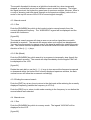
7 Controls and Function
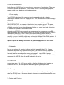
7.1 Front Panel
{figure 1}
7.1.1 Power Switch
Press this switch to power the radio on/off. In addition the separate infrared remote
controller (supplied) will enable the AR7000 to be switched off. Note: The AR7000
may be switched off and on via the infrared remote only if the AR7000 mechanical
front panel switch remains depressed.
7.1.2 Headphone Socket
A 3.5mm headphone jack plug can be connected for personal monitoring. When
connected, the built-in speaker will be disconnected (audio automatically cut off).
7.1.3 LCD Display
A built-in 3.1" DSTN type NTSC colour LCD (Liquid Crystal Display) shows operating
conditions.
7.1.4 Keypad
Press the keys to enter necessary data/information into the receiver. Some particular
keys are assigned with dual functions, press and hold for more than one second to
access the dual function. Only valid key(s) will be accepted.
Primary function “PUSH” - orange lettering, quick tap only required.
Secondary function “PRESS” (and HOLD) - white lettering, hold for more than one
second.
Many functions are also available from the infrared controller.
7.1.5 Main Dial
Rotate the main dial to select the receive frequency. This dial is also used to select
various receiver parameters via menus.
7.1.6 Infrared receive window
Point the infrared hand controller at this front panel window when the receiver is
operated via the infrared hand controller.
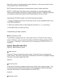
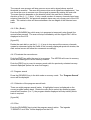
7.2 Rear Panel
{figure 2}
7.2.1 AUX connector
This 8-pin 270º DIN socket provides output for audio, squelch switching, etc. Refer
to section 10 of this manual for pin-out details.
7.2.2 Video output switch
This slide switch selects the video format of either PAL or NTSC. The default
position is NTSC. Note: When PAL is selected the built-in LCD is disabled.
7.2.3 Video output terminal
This PHONO socket provides a composite video output to the external monitor in
either NTSC or PAL depending upon selection.
7.2.4 Audio output
This PHONO socket provides audio output to external equipment (such as a
camcorder etc). The output level is constant irrespective of the volume control
setting.
7.2.5 Aerial (antenna) terminal
A BNC type connector is provided for aerial connection. A 50 OHM impedance aerial
is recommended for this receiver. If wire aerial is connected any suitable Balun may
be used for optimum results.
7.2.6 RS232C Connector
A D-SUB 9-pin connector is provided for straight lead connection with most types of
PC via an RS232C connection. Refer to section 9 of this manual for connection
information.
7.2.7 DC socket
Connect the supplied a.c.-d.c. adapter to this socket. The applicable standard for the
jack/plug is RC5320A(EIAJ)/IEC13010. This plug/socket is wired centre positive, if
using a different power supply, select a unit which is regulated producing 12 to 14V
d.c. with a current capacity of at least 2.0A.
7.2.8 External speaker socket
This 3.5mm jack socket is provided for connection to an external speaker (8 OHMS).
Audio level is variable via the volume control. When an external speaker is used, the
built-in speaker will be disabled.
8 Before the set is switched on
8.1 Power supply
Ensure the power switch is in OFF position (switch protruding). Connect the d.c. plug
of the standard power supply to the power input socket which is found on the rear
panel of the AR7000.
8.2 Video format switch
Ensure that rear panel NTSC is selected to enable internal LCD operation.
8.3 Aerial connection
Connect a suitably terminated BNC aerial to the BNC aerial socket on the rear panel
of the AR7000.
8.4 Power it up
Make sure that all necessary connections are made, and double check that the
power supply voltage/polarity are correct. Press the front panel power switch to
switch the AR7000 on. The dial mode set-up will be displayed on the LCD following
the CPU initialising.
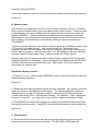
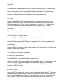
9 Keyboard (basic operation)
The AR7000 is designed to be operated using the main dial and keyboard.
Explanation for usage of each key and the main dial follows:
{figure 3}
VOL. UP [↑] Increase the volume level, move the cursor upward.
VOL DOWN [↓] Reduce the volume level, move the cursor downward.
[←] Acts as a back space and is used to move the cursor. It also has the same
action as rotating the main dial anti-clockwise in many menus.
[→] Move the cursor. It also has the same action as rotating the main dial clockwise
in many menus.
[ESC] Terminate the on-going key sequence returning to the previously selected
menu.
Main dial is used to tune through the receive frequency. Also used to select receive
mode, squelch level, IF BW and AGC.
[ENT] Determine the selection of data/functions (used to finalise selection).
[STEP 1] PUSH (tap) with a finger (only momentarily) to enter the numeric data
which is printed directly on the key in orange (primary function). PRESS (longer than
one second) to select the function which is printed above the key in white.
Operating the AR7000 is simple if you follow the basic principles:1. Press (and hold for more than one second) the key of your intended function such
as [STEP] and [MODE].
2. Select your desired value or data using the main dial or [←] [→] arrow keys.
3. Press [ENT] key to confirm the entry.
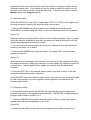
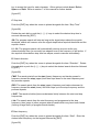
Understanding the basic operation
Basic operating modes
The AR7000 is equipped with the 2 dial modes (VFO-A, VFO-B) and one memory
mode. Push the [→] key to scroll from VFO-A to VFO-B to Memory back to VFO-A...
in sequence. Push the [←] key to scroll VFO-A to Memory to VFO-B to VFO-A...in
sequence.
{figure 4} Shows Dial mode VFO-A
{figure 5} Shows Dial mode VFO-B
{figure 6} Shows Memory mode
Audio volume
Push the [↑] key to increase the audio volume. Push the [↓] key to decrease the
audio volume. The audio volume level is indicated on the LCD as a graphical triangle
bar meter in the upper right of the LCD.
{figure 7}
K.Lock key lock
Press the [K.Lock] key to disable all other keys until [K.Lock] is pressed again. This
is useful to prevent accidental movement of receive frequency while monitoring an
important transmission or receiving data such as NAVTEX.
{figure 8}
Squelch control
Press the [SQL] key. The SQ legend on the LCD will reverse to negative image.
Push the [SQL] key again to toggle “OPN” (open) and “S0 ~ S9, +10, +20 ~ +60”
(close). When a range between S0 & +60 is displayed, rotate the main dial to
change the squelch threshold value. If you want the squelch open press the [ENT]
key while the “OPN” legend is displayed.
In order to obtain an optimum squelch threshold level, press the [SQL] key, the “SQ”
legend on the LCD will reverse to a negative image. Press the [SQL] key to initially
select “S0”. Either rotate the main dial or [←] [→] keys to vary the squelch between
S0 and S9, & +10 & +60 until the background noise (in the absence of a signal) is
quieted, if a transmission is in progress, it may not be possible to close the squelch.
Press the [ENT] key when you have selected an optimum squelch threshold.
{figure 9}
The squelch threshold level is displayed as a blue horizontal bar meter at the bottom
of the signal meter (S-meter bar graph). It is important that the squelch level is not
set too high or weaker signals will not be audible (as the squelch will remain closed).
NOTE: The scan/search process will not begin when the received signal is below
squelch threshold.
{figure 10}
A Dial mode
The AR7000 is equipped with the 2 dial modes, VFO-A and VFO-B. You can
manually select/enter the receive frequency, receive mode, etc.
VFO is a historical term for Variable Frequency Oscillator, today it is used to describe
a facility which stores frequency & mode which may be tuned.
Manual frequency entry
Example 1
Enter the frequency of 209.75MHz in VFO-A.
1. Push either the [←] or [→] key to access VFO-A (upper of the two large frequency
readouts).
2. Press the [MODE] key for more than one second. Rotate the main dial or push
the [←] or [→] keys to obtain the LCD legend “AUT” (automode, where the AR7000
automatically selects the appropriate receive mode, channel step and IF bandwidth
for the displayed frequency) followed by [ENT].
{figure 11}
3. Push [2] [0] [9] [.] [7] [5] [ENT]
{figure 12}
Example 2
Enter 954kHz, still using VFO-A.
Push [0] [.] [9] [5] [4] [ENT]
From there rotate the main dial to tune around the medium wave band radio stations.
{figure 13}
B Memory mode
The AR7000 is equipped with a total of 1500 memory channels (100 ch x 15 banks).
Each memory channel can be given an alpha-numeric ident of up to 7 letters for ease
of identification, the ident is displayed to the upper left of the frequency (under the
legend “MEMORY”). Memory channels are useful stores for regularly monitored
frequencies to save laborious key strokes and repetitiveness, they are also used for
fast reviewing of channels when automatically hunting for active transmissions “SCANNING”.
To quickly transfer data from dial mode to memory, press the [FREQ] key while in the
VFO mode, do not hold the key… just a quick tap will do! The current (top)
frequency on the LCD will change colour to red. Press the [ENT] key to transfer the
receive data (frequency, receive mode, AGC, ATT, SQ setting) to the next available
memory channel of the present bank. Refer to section 2.6 of this manual.
Memory data may be entered into each channel & bank using the EDIT facility then
swapped around and rearranged. Various frequencies are entered into the AR7000
memory channels during manufacture & test. See section 3.5 of this manual for
information on memory edit.
Recall the memory channel
1. Push the [←] or [→] key to obtain MEMORY mode on the screen (upper of the two
large frequency readouts).
{figure 14}
2. Rotate the main dial to step through the memory channels. Any memory channels
which do not have valid data will not be shown. The channel and bank number is
displayed at the top right of frequency readout in the format 00 to 99 for channel
number followed by 00 to 14 for the bank number. For example, “21/03” represents
channel 21, bank 03… you may refer to it as 2103 for ease of expression (ch/bk).
3. Press [BANK] (the bank LCD legend will reverse) and rotate the main dial to step
through the memory banks. Push [ENT] when the desired memory bank is selected.
{figure 15}
C Search mode
In the search mode, the receiver will step through the frequency spectrum at the
specified step size looking for active signals. The AR7000's LCD display will
graphically show such radio activities while the search is in progress (rather like an
aeroplane vapour trail). It is possible to tune the radio by tracing a cursor onto the
frequency you want to monitor (using the main dial). There are two types of search,
Manual search and Program search.
C-1 Manual search
When the AR7000 is in the “DIAL” mode (either VFO-A or VFO-B on the upper line of
the large frequency readout) the manual search can be used.
1. Push the [RUN/BRK] key while in dial mode to initiate the manual search.
“M.SEARCH” is shown along with “Run” on the LCD while the search is in progress.
{figure 16}
Resultant spectrum analysis will be shown as the search progresses. When a signal
above the squelch threshold is received, the search will stop at that point until such
signal has disappeared and squelch closes.
2. You can force the manual search to resume by rotating the main dial (whichever
direction you desire, up or down).
3. Press the [RUN/BRK] key to stop the search, the legend “Brk” confirms break
(pause) on the LCD.
{figure17}
While the search is stopped in this situation, you can tune to other frequencies within
the display window by rotating the main dial, a cursor follows the frequency spectrum
on the screen. Active signals will be audible, the squelch may be adjusted as
required.
4. Press the [ENT] key in the manual search mode if you wish to return to the dial
mode still retaining the present frequency.
Press the [ESC] key in the manual search mode if you wish to return to the dial mode
but with the frequency you were originally receiving before you switched to the
manual search mode.
C-2 Program search
In the program search mode, the AR7000 will step through the pre-programmed
frequency spectrum in the specified increment size. The AR7000 is equipped with 8
program search banks, number 0 to 7.
1. Press the [SEARCH] key while in the dial mode or memory mode, the program
search menu will then be displayed on the LCD.
{figure 18}
2. Rotate the main dial to select the desired program search bank number 0 to 7.
3. Push the [RUN/BRK] key to start the program search process, the LCD displays
the legends “P.SEARCH” (in light blue) and “Run” (in red) to confirm selection.
{figure 19}
Remember, the squelch must be advanced high enough to cancel the background
noise or the search process will not progress as the AR7000 will think that it has
found a busy frequency. Press [SQL] and rotate the main dial clockwise until
background noise in cancelled then press [ENT] to accept the new value.
Resultant frequency spectrum analysis will be displayed on the lower section of the
LCD (in green) as the search process advances. Strong signals appear as high
vertical bars and weak or no signal as low bars. When a signal above the squelch
threshold is received, the search process will stop on the active frequency and you
will hear the transmission (if the volume is high enough) until the busy signal has
disappeared (or in case of time controlled search is selected, after the specified time
has elapsed). Rotate the main dial to force the search onward.
When the search reaches the top frequency limit, the search jumps back to the
lowest frequency limit then advances forward again (depending on setting of forward,
reverse, loop or link in the configuration menu).
4. Push the [RUN/BRK] key while the program search is in progress to stop the
search. The legend “Brk” will be will be displayed in place of “Run” on the LCD.
{figure 20}
You may manually tune around by rotating the main dial, a cursor (vertical dark band
through the spectrum display) follows your movement through the limits of the display
window.
5. Push the [ENT] or [ESC] key to return to the program search menu to make
changes or to select a different search bank.
6. Push the [ESC] key to return to the operating mode before the program search
process began.
D Scan mode
D-1 Manual scan
1. While in the memory mode (press the [←] or [→] key until “MEMORY” is
displayed) press the [BANK] key. The bank number legend will reverse contrast on
the LCD. Rotate the main dial to select the desired bank number, there are 15 scan
banks numbered 0 to 14, accept the selection by pressing [ENT].
{figure 21}
2. Push the [RUN/BRK] key, the legend “M.SCAN” will appear on the LCD to confirm
selection and the scan process will start.
{figure 22}
Remember, the squelch must be advanced high enough to cancel the background
noise or the scan process will not progress as the AR7000 will think that it has found
a busy channel. Press [SQL] and rotate the main dial clockwise until background
noise in cancelled then press [ENT] to accept the new value.
Resultant frequency spectrum analysis (representing channel activity) will be
displayed on the lower section of the LCD (in green) as the scan process advances.
Strong signals appear as high vertical bars and weak or no signal as low bars. When
a signal above the squelch threshold is received, the scan process will stop on the
active channel and you will hear the transmission (if the volume is high enough) until
the busy signal has disappeared. Rotate the main dial to force the scan to resume in
whichever direction you choose.
3. While the scan is stopped, rotate the main dial to force the scan resume. When
the scan reaches the top channel number, it reverses back progressing toward the
lowest channel number, then advances forward again.
4. Push the [RUN/BRK] key while scanning. The scan will stop and the legend “Brk”
will be displayed on the LCD. Rotate the main dial to step through the memory
channels, a cursor (vertical dark band through the spectrum display) follows your
movement through the limits of the display window.
{figure 23}
5. Push the [ENT] key while scanning. The receiver will return to the memory mode
retaining the present frequency. Push the [ESC] key to go back to the memory
channel used prior to the selection of manual scan mode.
D-2 Program scan
1. Press the [SCAN] key while in dial mode or memory mode. The program scan
menu will appear on the LCD.
{figure 24}
2. Rotate the main dial to select your desired program scan group number. There
are eight program scan groups 0 to 7. These are not the same as the 15 memory
banks, but are special program scan groups where start / stop memory banks &
channels may be nominated along with direction of scan, time controlled scan value
etc. Any number of adjacent memory channels and banks may be nominated for
start / stop limits for each of the eight program scan groups.
3. Push the [RUN/BRK] key, the legend “P.SCAN” will be displayed along with the
legend “Run”. The program scan process will commence for the chosen memory
group (providing memory channels contain data).
The scan will stop when the active signal above squelch threshold is received. The
scan resumes either when such signal has disappeared, or in case of time controlled
scan, when the pre-determined time has elapsed. Rotate the main dial to force the
scan to resume.
{figure 25}
4. Push the [RUN/BRK] key while scanning to pause the scan process. The scan will
stop and the legend “Brk” will be displayed on the LCD. Rotate the main dial to step
through the memory channels, a cursor (vertical dark band through the spectrum
display) follows your movement through the limits of the display window.
{figure 26}
5. Push the [ENT] or [ESC] key to return to the program scan menu to make changes
or to select a different scan group.
6. Push the [ESC] key to go back to the operating mode in use prior to program scan
selection.
AR7000 Reference manual
1. Basic operation
1.1 Selection of the basic operating mode
Push the [→] key to advance the operating mode clockwise, VFO-A to VFO-B to
MEMORY to VFO-A..., push the [←] key to select anti-clockwise.
{figure 27}
{figure 28}
{figure 29}
1.2 Audio volume
Push the [↑] key to increase the audio volume, push the [↓ ] key to decrease (lower)
the audio volume level.
{figure 30}
1.3 Key lock
Push the [K.Lock] key to lock the keypad of the radio, this is useful to prevent
accidental frequency change, the LCD legend “Lock” confirms operation. Push the
[K.Lock] key again to disengage the lock as a toggle.
{figure 31}
1.4 Squelch control
To set the squelch permanently open
Press the [SQL] key so that the “OPN” legend appears on the LCD followed by
[ENT].
{figure 32}
To adjust the squelch threshold level
Press the [SQL] key to toggle “OPN” and “S-meter value”. While S-meter value is
indicated, rotate the main dial or push the [→] or [←] keys to vary the squelch Smeter value.
Push the [ENT] key when you have selected the desired value.
{figure 33}
The squelch value is indicated as a blue line displayed underneath the S-meter.
Note: The scan/search will only begin when the background signal (noise) is below
squelch threshold.
1.5 AGC setting
The AR7000 is provided with AGC (Automatic Gain Control) positions, “FAST” and
“SLOW”. Each press of the [AGC] key toggles between the FAST and SLOW
positions. A fast setting is usually best for CW operation when receiving Morse code
and other data modes, at all other times SLOW is usually the best choice.
{figure 34}
1.6 ATT (Attenuator) setting
The AR7000 is equipped with a 10dB RF attenuator, this can be useful for reducing
the effect of strong local signals which otherwise may lead to “mixing” inside the
receiver’s circuitry (common to all receivers). Each press of the [ATT] key will toggle
the attenuator ON and OFF.
The legends have the following meaning:
ATT
Attenuator legend represents ON, set is least sensitive.
No legend. Set is most sensitive, attenuator OFF.
Note: Do not be confused by the “OFF” legend under the attenuator status, this
refers to the IF SHIFT facility.
{figure 35}
1.7 IF Shift (WFM,AM,CW,USB,LSB only)
The AR7000 is equipped with an IF SHIFT control which can vary the centre
frequency of the IF within a range of +/-8500Hz at a rate of 100Hz without affecting
the received signal. This feature is very useful for moving the receive passband
away from adjacent channel interference, especially on the short wave and medium
wave bands.
{figure 36}
Operating the IF Shift
Press the [IF SFT] key, the IF SHIFT legend will reverse to a negative image to
confirm selection.
Each press of the [IF SFT] key will toggle the status between current value and OFF.
Either rotate the main dial or press the [→] or [←] keys to vary the IF shift frequency
as required. Press the [ENT] key when the optimum IF Shift frequency is obtained.
2 Dial Mode
Both types of dial mode (VFO-A) and (VFO-B) operate in exactly the same manner.
Both are referred to here as dial mode.
2.1 Display
An example of the LCD display is shown here when dial mode is selected.
{figure 38}
Note: Mch 03/02 represents the memory channel number 3 on the memory bank
number 2.
2.2 Frequency Selection
Direct entry via key-pad
Push the numeric keys to enter the frequency in a MHz order followed by [ENT], use
the decimal point after the MHz entry such as [8] [1] [.] [3] [ENT] for 81.300 MHz,
there is no need to use proceeding or trailing zeros.
{figure 39}
Tuning via the main dial
Rotate the main dial while in dial mode to tune through the frequency spectrum at
the pre-determined step size. Clockwise rotation increases frequency while antclockwise rotation decreases frequency.
2.3 Selection of frequency step
The step size cannot be altered while the AR7000 is in AUTO MODE (while the
legend “AUT” displayed on the LCD), select another receive mode then press the
[STEP] key.
The step frequency legend will reverse to negative image. Tap in an appropriate
step size via the key-pad using kilo Hertz format (thousands of Hz) followed by [ENT],
i.e. for 25 kHz type [2] [5] [ENT]. Acceptable step size is anything between 0.01 kHz
(10 Hz) and 1000 kHz (1 MHz). The back space key [←] will act as delete key if a
mistake is made.
When AUTO MODE is selected, the step size is selected automatically by the
AR7000 CPU appropriate to the market area, this is taken from a detailed bandplan
entered into the AR7000 during manufacture.
{figure 40}
2.4 Selection of receive mode
The AR7000 provides the following receive modes:AUT: When auto mode is selected, the AR7000 automatically selects the
appropriate step size, IF BW and receive mode on your behalf using its factory preprogrammed band plan data.
USB: Upper Side Band, used by radio amateurs, prolific on the HF bands. Also
used by commercial HF utility stations.
LSB: Lower Side Band, used by radio amateurs below 10 MHz.
CW1: CW with a 400Hz beat tone, Continuous Wave = Morse code.
CW2: CW with a 600Hz beat tone
CW3: CW with an 800Hz beat tone
AM: Amplitude Modulation, LW, MW & HF broadcast, airband.
NFM: Narrow band Frequency Modulation, most point to point communications on
VHF/UHF.
WFM: Wide band Frequency Modulation, Band-II VHF, TV
Selection of Receive Mode
Press the [MODE] key. The LCD legend displaying the receive mode will reverse to
a negative image.
{figure 41}
Either rotate the main dial or press the [←] or [→] keys which carousel through the
receive modes as per diagram. Press [ENT] when the desired receive mode is
displayed.
{figure 42}
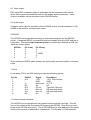
2.5 Selection of IF bandwidth
The AR7000 can be operated using the various bandwidths in accordance with the
table below:{figure 43}
Receive Mode
USB/LSB
CW1,CW2,CW3
AM
WFM
NFM *
Selection of IF BW
2kHz, 2.5kHz, 3kHz
50Hz,150Hz,250Hz,500Hz,800Hz
3kHz,6kHz,8kHz
150kHz
15kHz-H, 15kHz-L
* NFM mode operates with a fixed 15kHz IF bandwidth but with the selectable option
of wide audio frequency response (15kH) and narrow response (15kL).
The wider the filter, the better the audio fidelity… there is an increased chance of
adjacent channel interference with a wider IF bandwidth. The best setting will
depend upon listening conditions.
Selection of IF BW (IF bandwidth)
Press the [IF BW] key. The LCD legend displaying the IF BW will reverse to negative
image. Either rotate the main dial or press the [←] or [→] keys to select an
appropriate IF bandwidth. Press the [ENT] key when the desired IF BW is selected.
{figure 44}
2.6 Transfer data from dial mode to memory
Press the [FREQ] key while in the VFO mode, do not hold the key… just a quick tap
will do! The current (top) frequency on the LCD will turn to a red colour. Press the
[ENT] key to transfer the receive data (frequency, receive mode, AGC, ATT, SQ
setting) to the next available memory channel of the present bank.
3 Memory mode
The AR7000 is equipped with a total of 1500 memory channels arranged as 15
memory banks 0 to 14, each containing 100 channels numbered 00 to 99. Each
memory channel can be tagged with a text ident of up to seven characters.
3.1 Display
A typical example of the memory channel mode is as follows:
{figure 45}
The memory channel mode looks similar to the VFO mode with the following
exceptions:1) A text ident (comment) may be shown should you choose.
{figure 45}
2) Memory channel number and memory bank number are shown as per the
illustration:-
{figure 45}
3.2 Memory channel
In the memory channel mode, either rotate the main dial to select the memory
channel or use the [←] [→] keys. Memory channels with no valid data will be ignored
(skipped = not shown).
3.3 Memory bank
In the memory mode, press the [BANK] key. The LCD bank legend will reverse to a
negative image. Either rotate the main dial or use the [←] [→] keys to select the
memory bank. Press [ENT] when the desired bank number is displayed.
{figure 46}
3.4 Transfer data from memory to dial mode
While in memory channel mode, press the [FREQ] key (only a quick tap is required).
The frequency of the displayed memory channel will turn red, press [ENT].
{figure 47}
The frequency data will be transferred to VFO-A (which is always the bottom
displayed VFO while in memory recall mode).
{figure 48}
3.5 Memory data edit
Press the [EDIT] key while in the dial mode or memory channel mode. The memory
edit menu will be displayed.
{figure 49}
Each press of the [↑] or [↓] key will move the “>” (red cursor) up and down. Place
the cursor “>” along side the function which you would like to perform, followed by
[ENT].
3.5.1 Channel Edit and Delete
When the Ch Edit/Del menu is selected (as per section 3.5) the LCD will show:{figure 50}
A Selection of memory channel to edit
Press the [EDIT] key to select the memory function menu. While the “>” cursor is
along side the menu item “Ch Edit/Del”, press the [ENT] key. The memory edit
menu will be displayed, a quick press of the [←] or [→] keys will highlight the
CHANNEL (00 to 99) and BANK numbers (00 to 14) as a toggle by displaying a
negative image over the required selection (do not hold the arrow keys too long, just
a quick press is required).
Rotate the main dial to scroll through memory channel numbers or bank numbers as
appropriate. Memory channels with no valid data or items with no specific data
stored will be displayed as “- - - -“.
B Selection of data to edit
While in the memory edit menu, press the [↑] or [↓] key to move the red cursor “>” to
the position where you wish to edit (frequency, mode, IF-BW, Name, Ch Pass, Ch
Delete) followed by [ENT].
B-1 Change of frequency
Place the cursor “>” along side the receive Frequency followed by [ENT]. The
present frequency will change to a negative image. Tap in the new desired
frequency via the numeric keypad followed by [ENT].
{figure 51}
B-2 Change of receive mode
Place the cursor “>” along side the receive Mode followed by [ENT]. The present
receive mode will change to a negative image. Either rotate the main dial or press
the [←] or [→] keys until the desired receive mode appears (USB, LSB, CW1, CW2,
CW3, AM, NFM, WFM, AUT). Press [ENT] to confirm your selection.
{figure 52}
B-3 Change of IF-BW
Place the cursor “>” along side the IF-BW followed by [ENT]. The IF-BW will turn to
a negative image. Either rotate the main dial or press the [←] or [→] keys until the
desired IF-BW appears (the selection available depends on current receive mode).
Press [ENT] to confirm your selection. When AUT has been selected as the current
receive mode, IF-BW will be automatically selected by the AR7000 CPU mapped
band plan, for this reason you cannot change the IF-BW when AUT receive mode is
selected, the IF-BW will display “- - - -“ and cannot be changed.
{figure 53}
B-4 Change of text/ident
Place the cursor “>” along side the test ident Name followed by [ENT].
{figure 54}
The Name Edit screen will be displayed. Your desired text ident may now be
entered or edited. Use the [↑] and [↓] keys to select character line number, use the
main dial to move along each line, use the [←] and [→] keys to move along the
seven character text ident, use the [ENT] key to accept the input for each character.
Other options include Insert, Delete, Space and Quit. Refer to section 7 of this
manual for further details.
{figure 55}
B-5 Channel pass
Any memory channels which you would like to skip in program scan or manual
scan can be registered as a pass channel. Place the cursor “>” along side the Ch
Pass followed by [ENT], the ON/OFF legend will turn to negative image. Either
rotate the main dial or press the [←] or [→] keys to toggle the pass status ON/OFF.
Press the [ENT] key when the desired selection has been made.
{figure 56}
B-6 Delete
Place the cursor “>” along side Ch Delete followed by [ENT]. The currently displayed
memory contents will be completely erased in one go and cannot be restored
afterward.
{figure 57}
3.5.2 Copy
Press the [EDIT] key to select the memory function menu. While the “>” cursor is
along side the menu item “Ch Copy” press the [ENT] key. When Ch Copy is
selected the following screen will be displayed:{figure 58} {figure 59}
While in the Ch Copy menu, press the [↑] or [↓] key to move the red cursor “>” to the
position where you wish to copy the memory from (“Source”) and to (“Dist”) followed
by [ENT].
A Selection of original memory (source)
Press the [ENT] key when the cursor “>” is next to the “Source”. The line represents
CHANNEL (00 to 99) and BANK (00 to 14) numbers. The channel number will
reverse to a negative image to conform selection. Press the [←] or [→] keys to
toggle between channel number and bank number. Rotate the main dial to select the
desired channel number and bank number respectively followed by [ENT].
{figure 60}
B Selection of distant memory (destination)
Press the [ENT] key when the cursor “>” is next to the “Dist”. The channel number of
the distant memory will reverse to a negative image. Press the [←] or [→] keys to
toggle between channel number and bank number. Rotate the main dial to select the
desired memory channel and bank number for the distant memory channel. Press
[ENT].
{figure 61}
C Executing copy
Now that both source memory and distant memory channel have been selected,
press the [↑] and [↓] keys to move the cursor “>” next to the legend “Copy” then
press [ENT]. The frequency and mode of the distant (destination) memory will
change to that of the source memory… both memory channels are now identical.
{figure 62}
D Exit from COPY
To return to the “Memory Function” menu, either press the [ESC] key or move the
cursor “>” to the “QUIT” legend then press [ENT], this terminates the copy session.
You are now back to the memory function menu.
{function 63}
3.5.3 Move
All the memory function menus manipulate in a similar manner. When the “Ch
Move” menu is selected via the memory function menu, the following screen will be
displayed:{figure 64} {figure 65}
Press the [↑] and [↓] keys to move the cursor “>” next to the legend “Ch Move” then
press [ENT].
A Selection of source memory channel
Press the [ENT] key when the cursor “>” is next to “Source”. The channel number
will reverse to a negative image to conform selection. Press the [←] or [→] keys to
toggle between channel number and bank number. Rotate the main dial to select the
desired channel number and bank number respectively followed by [ENT].
{figure 66}
B Selection of distant memory channel
Press the [ENT] key when the cursor “>” is next to “Dist”. The channel number of the
distant memory will reverse to a negative image. Press the [←] or [→] keys to toggle
between channel number and bank number. Rotate the main dial to select the
desired memory channel and bank number for the distant memory channel. Press
[ENT]
{figure 67}
C Executing the channel move
Now that both source memory and distant memory channel have been selected,
press the [↑] and [↓] keys to move the cursor “>” next to the legend “Move” then
press [ENT]. Memory contents will have been transferred to the distant channel,
and the source channel is now empty with no memory contents.
{figure 68}
D Exit from the memory channel move
To return to the “Memory Function” menu, either press the [ESC] key or move the
cursor “>” to the “QUIT” legend then press [ENT] to terminate the move session. You
are now back to the memory function menu.
{figure 69}
3.5.4 Swap
All the memory function menus manipulate in a similar manner. When the “Ch
Swap” menu is selected via the memory function menu, the following screen will be
displayed:{figure 70} {figure 71}
A Selection of source memory channel
Press the [ENT] key when the cursor “>” is next to “Source”. The channel number
will reverse to a negative image to conform selection. Press the [←] or [→] keys to
toggle between channel number and bank number. Rotate the main dial to select the
desired channel number and bank number respectively followed by [ENT].
{figure 72}
B Selection of distant memory channel
Press the [ENT] key when the cursor “>” is next to “Dist”. The channel number of the
distant memory will reverse to a negative image. Press the [←] or [→] keys to toggle
between channel number and bank number. Rotate the main dial to select the
desired memory channel and bank number for the distant memory channel. Press
[ENT]
{figure 73}
C Executing the swap
Now that both source memory and distant memory channel have been selected,
press the [↑] and [↓] keys to move the cursor “>” next to the legend “Swap” then
press [ENT]. The memory contents of each channel are now swapped.
{figure 74} {figure 75}
D Exit from the swap
To return to the “Memory Function” menu, either press the [ESC] key or move the
cursor “>” to the “QUIT” legend then press [ENT] to terminate the swap session. You
are now back to the memory function menu.
{figure 76}
3.5.5 Bank delete
Move the cursor “>” along side the “Bank Del” legend of the “Memory Function” menu
then press [ENT]. When “Bank Del” is selected, the bank number (currently
displayed as “- -“) will reverse to a negative image. Rotate the main dial or press the
[←] or [→] keys to select the desired memory bank from which you wish to erase the
contents. Press the [ENT] key to delete all memory data from the selected memory
bank. All memory channels (of the selected bank) will be deleted in one go and the
cursor will move back along side the “Bank Del” item of the menu.
{figure 77}
3.5.6 Terminate the memory edit
To return to memory channel mode, either press the [ESC] key or move the cursor
“>” to the “QUIT” legend then press [ENT] to terminate the session. You are now
back to the memory function menu.
{figure78}
4 Search and Scan
4.1 Definition and convention
It is important to understand the fundamental difference between SEARCH and
SCAN modes.
Search:
The AR7000 steps through the frequency spectrum looking for transmissions, the
squelch control needs careful setting so that the background noise is just cancelled, if
the squelch is set too high, weak signals may be missed. The AR7000 steps through
the spectrum using the selected mode and step size (including automatic selection
using the automode bandplan data programmed into the AR7000 CPU). Unwanted
active frequencies may be skipped using the PASS facility.
Manual Search: Steps through the frequency spectrum from the current displayed
frequency in DIAL MODE. The legend “M.SEARCH” confirms operation. The main
dial may be used to reverse the direction of manual search, a spectrum trace is
displayed indicating progress.
Program search: The upper and lower frequency limits for the search process may
be programmed along with receive frequency, step size and direction. The search
process then takes place between these limits, looping back to the start when the
end has been reached (depending on the programmed search direction options).
Scan:
The AR7000 quickly reviews the contents of the memory channels looking for
activity. Different frequency bands and modes of reception may be scanned
together.
Manual scan: The current bank only is scanned.
Program scan: Several banks and channels may be grouped together in a single
scan adding great flexibility to the scan facility.
Note: It is normal to hear internal low volume “clicks” caused by relays inside the
AR7000 when certain frequency banks are selected.
4.2 Display and Run/Brk
While the search/scan is in progress, the screen will display the spectrum analysis
received so far (up to a maximum of 80 samples).
{figure 79}
This figure is a typical example of the LCD screen showing such activity. While the
search/scan is in action, the legend “Run” is displayed on the LCD in a red box. The
LCD legend “Brk” is displayed when the process is temporarily stopped.
Note: While the search/scan is in action only the following keys are operative:[RUN/BRK] [←] [→] [AGC] [SQL] [ATT] [IF SFT] [K.Lock]
The main dial and volume keys are also operative but other keys are disabled.
The squelch threshold is shown as a light blue horizontal line, when temporarily
stopped, a vertical dark cursor bar indicates current receive frequency. The larger
the signal received, the higher the green bars of spectrum analysis, however, there is
no way of showing real time signal strength on the spectrum display (refer to the smeter in the top left corner of the LCD for current signal strength).
4.3 Manual search
4.3.1 Run
Push the [RUN/BRK] key while in dial mode to start a manual search from the
currently displayed frequency. The “M.SEARCH” legend will be displayed and the
search will commence.
{figure 80}
The manual search process will stop as soon as an active signal above squelch
threshold is received. The search will resume when such signal has disappeared.
You can force the search to resume even if the signal is present by rotating the main
dial. The search direction depends on the direction which the main dial is rotated or
direction of the [←] [→] keys.
4.3.2 Brk (Break)
Push the [RUN/BRK] key while search is in progress to temporarily stop (break) the
manual search process. The search will stop immediately and the legend ”Brk” will
be displayed on the LCD.
{figure 81}
Rotate the main dial or use the [←] [→] keys to tune around the frequencies upward
or downward within the limits of the currently displayed spectrum window, the dark
vertical cursor will follow the movement accordingly.
4.3.3 Ending the manual search
Push the [ENT] key at any time to return to the dial mode while retaining the currently
displayed frequency (transfer the frequency to VFO-A).
Push the [ESC] key to return to dial mode reverting to the frequency in use before the
manual search was selected.
4.4 Manual scan
4.4.1 Run
Push the [RUN/BRK] key while in memory mode. The legend “M.SCAN” will be
displayed on the LCD.
{figure 82}
The manual scan process will stop as soon as an active signal above squelch
threshold is received. The scan will resume when such signal has disappeared. You
can force the scan to resume even if the signal is present by rotating the main dial.
The scan direction depends on the direction which the main dial is rotated or
direction of the [←] [→] keys. If only a small number of memory channels have been
selected (less than 80), the spectrum analysis trace may only occupy part of the LCD
width. The vertical cursor will bounce between the two edges of the selected scan
bank.
4.4.2 Brk (Break)
Push the [RUN/BRK] key while scan is in progress to temporarily stop (break) the
manual scan process. The scan will stop immediately and the legend ”Brk” will be
displayed on the LCD.
{figure 83}
Rotate the main dial or use the [←] [→] keys to tune around the memory channels
upward or downward within the limits of the currently displayed spectrum window, the
dark vertical cursor will follow the movement accordingly.
4.4.3 Terminate the manual scan
Push the [ENT] key while the scan is in progress. The AR7000 will revert to memory
mode still retaining the current memory channel.
Push the [ESC] key to revert to memory mode with the previously selected memory
channel displayed (before the scan first began).
4.5 Program search
Press the [SEARCH] key in the dial mode or memory mode. The “Program Search”
menu will be displayed.
4.5.1 Selection of the program search bank
There are eight program search banks. A highlighted cursor is displayed on the
current program search bank. Rotate the main dial to select the desired program
search bank number (0 to 7), the program details displayed will help identify which
bank is required.
{figure 84}
4.5.2 Run
Push the [RUN/BRK] key to start the program search action. The legends
“P.SEARCH” and “Run” will be displayed on the LCD.
{figure 85}
When an active signal has been found the program search will stop. The search will
resume when the active signal has disappeared and squelch closes, or in case of
time controlled search, when a pre-determined time has elapsed. Rotate the main
dial or use the [←] [→] keys to force the search to resume, you cannot reverse the
direction of program search as it is defined in the programming menu.
4.5.3 Brk
Push the [RUN/BRK] key while program search is in progress to temporarily stop
(break) the search process. The search will stop immediately and the legend ”Brk”
will be displayed on the LCD. Rotate the main dial or use the [←] [→] keys to tune
around the frequencies upward or downward within the limits of the currently
displayed spectrum window, the dark vertical cursor will follow the movement
accordingly.
{figure 86}
4.5.4 Terminate the program search
Push the [ENT] key or [ESC] key to revert to the Program Search menu screen.
Select “Quit” then push the [ENT] key to return to the dial mode while retaining the
currently displayed frequency (transfer the frequency to VFO-A). If autoStore is on,
this frequency will also be copied to the next available empty memory channel of the
specified bank.
Push the [ESC] key to return to dial mode reverting to the frequency in use before the
program search was selected.
4.5.5 Selection of the search parameter
A Selection of the parameter
Press [SEARCH] to access the Program Search menu.
Push the [↑] and [↓] keys to select the desired parameter which is to be altered, a red
cursor “>” moves up and down alongside the parameters which are available for
change. Push the [ENT] key to access each menu and use [ENT] to accept the
changes or [ESC] to abort.
B Program name
Push the [ENT] key when the cursor is placed alongside the item “Name”. The name
editor screen will appear ready to accept your desired text ident. Use the [↑] and [↓]
keys to select character line number, use the main dial to move along each line, use
the [←] and [→] keys to move along the seven character text ident, use the [ENT]
key to accept the input for each character. Other options include Insert, Delete,
Space and Quit. Refer to section 7 of this manual for further details.
{figure 87}
C Stop time
Push the [ENT] key when the cursor is placed alongside the item “Stop Time”.
{figure 88}
Rotate the main dial or push the [←] [→] keys to select the desired stop time in
seconds followed by [ENT].
SQ: The program search will stop as long as the signal stays above the squelch
threshold, search will resume once the signal drops below squelch threshold and the
squelch closes.
01 - 99: The program search will automatically resume as soon as the predetermined stop time (in seconds) has elapsed even if the frequency is still active. If
the squelch closes before stop time has elapse, search resumes immediately.
D Search direction
Push the [ENT] key when the cursor is placed alongside the item “Direction”. Rotate
the main dial or push the [←] [→] keys to select the desired search direction followed
by [ENT].
{figure 89}
FWD: The search starts from the start (lower) frequency and tracks upward in
frequency toward the stop (upper) limit then hops down to the start frequency and
the process repeats.
REV: The search starts from the stop (upper) frequency and tracks downward in
frequency toward the start (lower) limit then hops up to the stop frequency and the
process repeats.
LOOP: The search shuttles (bounces between limits) between the start and stop
frequencies.
Link: The search starts from the start frequency and progresses to the stop
frequency, then jumps to other program search banks which may have been linked
(forming a large family of program search banks).
E Start frequency
Push the [ENT] key when the cursor is placed alongside the item “Start”. Enter the
desired start frequency via the keypad followed by [ENT].
{figure 90}
Note: When inputting start and stop frequencies, the AR7000 automatically assigns
the lower frequency to the START and upper frequency to the STOP regardless of
which order then are entered.
F End frequency
Push the [ENT] key when the cursor is placed alongside the item “Stop”. Enter the
desired stop frequency followed by [ENT].
{figure 91}
G Step
Push the [ENT] key when the cursor is placed alongside the item “Step”.
{figure 92}
Enter the desired step size via the keypad in a kHz order followed by [ENT].
Acceptable step size is anything between 0.01 kHz (10 Hz) and 1000 kHz (1 MHz),
invalid entries will be ignored. i.e. for a step size of 25 kHz, key [2] [5] [ENT]. Note
that this sequence is inoperative when automode (AUT) has been selected (as the
AR7000 CPU automatically selects step size using its pre-programmed bandplan
data).
H Receive mode (Mode)
Push the [ENT] key when the cursor is placed alongside the item “Mode”. Rotate the
main dial or push the [←] [→] keys to select the desired receive mode followed by
[ENT].
{figure 93}
I IF bandwidth (BW)
Push the [ENT] key when the cursor is placed alongside the item “BW” (this is to the
right of mode entry). Rotate the main dial or push the [←] [→] keys to select an
appropriate bandwidth followed by [ENT]. Note that this sequence is inoperative
when the auto mode (AUT) has been selected.
{figure 94}
J Auto store (Store)
Push the [ENT] key when the cursor is placed alongside the item “Store”. Rotate the
main dial or push the [←] [→] keys to select one of the following positions:{figure 95}
O N: When active signals above the squelch threshold have been received, such
signals will be automatically stored in the empty channels of the designated memory
bank. When the memory bank becomes full, the auto store action will become
invalid, the search process will carry on regardless.
OVW: When active signals above squelch threshold have been received, such
signals will be stored from channel 00 up to channel 99 of the designated memory
bank in sequence. This auto store sequence will continue between channel 00 and
99 overwriting the previously stored data.
OFF: The auto store is inoperative (disabled).
K Store bank (Bank)
Push the [ENT] key when the cursor is placed alongside the item “Bank”. Rotate the
main dial or push the [←] [→] keys to select the desired memory bank (00 to 14) to
be used for auto store of active frequencies, then press [ENT].
{figure 96}
L Pass bank
Push the [ENT] key when the cursor is placed alongside the item “Pass Bank”.
Rotate the main dial or push the [←] [→] keys to select the desired pass bank (00 to
14) to be used, alternatively select “- -“ to disable the pass facility then press [ENT].
{figure 97}
M Quit
Push the [ENT] key when the cursor is placed alongside the item “Quit”. The LCD
will revert to whatever mode was active before the program search menu was
selected.
4.6 Program scan
Press the [SCAN] key in the dial mode or memory mode. The “Program Scan”
menu will be displayed.
{figure 98}
4.6.1 Selection of the program number
There are eight program scan groups. In the program scan menu screen rotate the
main dial to select the desired program scan group number from 0 to 7.
4.6.2 Run
Having selected the desired program scan number, push the [RUN/BRK] key to start
the program scan.
{figure 99}
The scan process will temporarily stop when an active signal above the squelch
threshold has been received. The scan process will resume when such signal has
disappeared. In the case of time control scan, the scan process will resume as soon
as the pre-determined stop time has elapsed or when the squelch closes should this
occur first (transmission ends). While the scan process has temporarily stopped,
rotate the main dial or press the [←] [→] keys to force the scan to resume.
4.6.3 Brk
To suspend program scan, press the [RUN/BRK] key while the scan is in progress.
The scan action will be suspended and the legend “Brk” will be displayed on the
LCD.
{figure 100}
Rotate the main dial or press the [←] [→] keys to step through other channels within
the spectrum display limits of the active LCD window. A dark vertical cursor indicates
current frequency.
4.6.4 Terminate the program scan
Push the [ENT] or [ESC] key to stop the scan action immediately and return to the
program scan menu screen.
4.6.5 Selection of the scan parameter
A Selection of the parameter
Push the [↑] and [↓] keys to select the desired parameter which is to be altered, a red
cursor “>” moves up and down alongside the parameters which are available for
change. Push the [ENT] key to access each menu and use [ENT] to accept the
changes or [ESC] to abort.
B Name
Push the [ENT] key when the cursor is placed alongside the item “Name”. The name
editor screen will appear ready to accept your desired text ident. Use the [↑] and [↓]
keys to select character line number, use the main dial to move along each line, use
the [←] and [→] keys to move along the seven character text ident, use the [ENT]
key to accept the input for each character. Other options include Insert, Delete,
Space and Quit. Refer to section 7 of this manual for further details.
{figure 101}
C Stop time
Push the [ENT] key when the cursor is placed alongside the item “Stop Time”.
Rotate the main dial or push the [←] [→] keys to select the desired stop time in
seconds followed by [ENT].
{figure 102}
SQ: The program scan will stop as long as the received signal stays above the
squelch threshold, scan will resume once the signal drops below squelch threshold
and the squelch closes.
01 - 99: The program scan will automatically resume as soon as the pre-determined
stop time (in seconds) has elapsed even if the frequency is still active. If the squelch
closes before stop time has elapse, scan resumes immediately.
D Scan direction
Push the [ENT] key when the cursor is placed alongside the item “Direction”. Rotate
the main dial or push the [←] [→] keys to select the desired search direction followed
by [ENT].
{figure 103}
FWD: The scan starts from the start ch/bank and scans toward the stop ch/bank
then hops down to the start ch/bank and the process repeats.
REV: The scan starts from the stop ch/bank and scans toward the start ch/bank
then hops to the stop ch/bank and the process repeats.
LOOP: The scan shuttles (bounces) between the start and stop ch/bank limits.
Link: The scan starts from the start ch/bank and progresses toward the stop ch/bank,
then jumps to other program scan groups which may have been linked (forming a
larger group).
E Start
Push the [ENT] key when the cursor is placed alongside the item “Start”. Enter the
desired start channel and bank using the main dial and [←] [→] keys followed by
[ENT].
{figure 104}
F Stop channel
Push the [ENT] key when the cursor is placed alongside the item “Stop”. Enter the
desired stop channel and bank using the main dial and [←] [→] keys followed by
[ENT].
{figure 105}
G Quit
Push the [ENT] key when the cursor is placed alongside the item “Quit”. The LCD
will revert to whatever mode was active before the program scan menu was selected.
5 Search pass/bank
The AR7000 has a PASS facility which enables unwanted busy frequencies to be
skipped during the scan and search processes.
5.1 Common pass bank
Memory bank number 14 has been assigned the special status of PASS BANK. Any
number of up to 100 frequencies stored in this memory bank will be ignored (skipped)
during the search and scan sequences.
{figure 106}
5.2 Program pass bank
In addition to the common pass bank, any one of the 14 banks (00 to 13) may be
assigned as an additional pass bank for program search. This makes a total of
200 frequencies (100 for the common pass bank plus a further 100 for the
additionally assigned pass bank). Refer to section 4.5.5.L of this manual for further
information regarding usage of the pass bank facility.
6 Other parameters
Push the [CONF] key in the dial mode or memory mode to access the configuration
menu. (The software version shown in this example is for reference only.)
{figure 107}
Push the [↑] and [↓] keys to select the desired parameter which is to be altered, a red
cursor “>” moves up and down alongside the parameters which are available for
change. Push the [ENT] key to access each menu and use [ENT] to accept the
changes or [ESC] to abort.
6.1 Beep
Push the [ENT] key when the cursor is placed alongside the item “Beep”.
{figure 108}
Rotate the main dial or push the [←] [→] keys to toggle the beep ON/OFF. Push the
[ENT] when the selection has been made.
6.2 Time
The AR7000 is equipped with one main clock plus four sub-clocks. Push the [ENT]
key when the cursor is placed alongside the item “Clock Setup”. Items relating to the
MAIN clock are prefixed “M” and the SUB-clock are prefixed “S”.
{figure109} {figure 110}
6.2.1 Main clock adjustment
When setting the MAIN clock, it doesn’t matter which sub-clock number (“Clock No.”)
is displayed (1 to 4).
A Date
Place the cursor alongside “M. Date” then press [ENT]. Push the [←] [→] keys to
alternate the position between Year, Month and Date. Rotate the main dial to select
the correct Year, Month and Date followed by [ENT].
{figure 111} {figure 112} {figure 113}
B Hour
Place the cursor alongside “M.Time” then press [ENT]. Push the [←] [→] keys to
alternate the position between Hour, Minute and Second. Rotate the main dial to set
the correct time followed by [ENT].
{figure 114}
C Name
Place the cursor alongside “M.Name” then press [ENT]. The name editor screen will
be displayed (refer to section 7 of this manual for further information on the name
editor). You can write an appropriate name for the time zone using a maximum of
seven characters.
{figure 115}
6.2.2 Sub-clock adjustment
A Selection of sub-clock
In the time selection menu, rotate the main dial to select any appropriate sub-clock
by number (Clock No. 1 to 4).
{figure 116}
A-1 Time difference
Place the cursor alongside “S. Diff”, press [ENT]. The time difference will be reverse
highlighted on the LCD, rotate the main dial to set the correct time difference (in
hours between -24 and 24 hours, 0 being the current time zone of the main clock),
followed by [ENT]. The local time and date is calculated by the AR7000 and
displayed in green in the lower half of the LCD.
{figure 117}
A-2 Name
Place the cursor alongside “S.Name” press [ENT]. The name editor screen will be
displayed (refer to section 7 of this manual for further information on the name
editor). You can write an appropriate name for the time zone using a maximum of
seven characters.
6.3 Timer
The AR7000 has five built-in timers which enable the radio to be automatically
switched on and off at preset times, this is very useful for unattended tape recording
of interesting broadcasts etc.
While in the “Configuration” menu, place the cursor alongside “Timer Setup” then
press [ENT]. The timer set-up menu screen will be displayed.
{figure 118} {figure 119}
6.3.1 Selection of timer
Rotate the main dial to select one of the five timers 0 to 4.
{figure 120}
6.3.2 Date
The cursor will initially be placed alongside “Date”, press [ENT]. Set the date you
wish the timer to become active, the current day is 00, tomorrow is 01 to a maximum
of 31 days. Use the main dial or [←] [→] keys select the date then press [ENT].
When you select the date as “00”, the timer will activate daily.
{figure 121}
6.3.3 Hour
Place the cursor alongside “Time”, press [ENT]. Push the [←] [→] keys to alternate
between hour and minute. Rotate the main dial to select the hour and minute you
wish the timer to activate then press [ENT].
{figure 122}
6.3.4 Operation of timer
Place the cursor alongside “Operation”, press [ENT]. The field initially displays “- - -“.
Rotate the main dial to alternate between “POWON” and “POWOFF”. Push the
[ENT] key to complete the sequence.
{figure 123}
A Setting the timer for switch-on
1. In the timer selection menu place the cursor alongside “Date” followed by [ENT].
Rotate the main dial to select the date required for switch on followed by [ENT]. The
current day is 00 with 31 being the maximum number of days ahead, selecting 00 will
cause the timer to event every day.
{figure 124}
2. Place the cursor alongside “Time” followed by [ENT]. Rotate the main dial to
select the hour/min, the [←] [→] keys are used to alternate between hours &
minutes. Complete the input with [ENT].
{figure 125}
3. Place the cursor alongside “Operation” followed by [ENT].
{figure 126}
Rotate the main dial to toggle between “POWON” and “POWOFF”. Select “POWON”
in this example followed by [ENT].
4. To arm the timer, place the cursor alongside “Power Off” followed by [ENT]. You
can alternatively push the [POWER] key from the infrared remote controller when
pointed at the AR7000 front panel sensor for the same effect.
{figure 127}
5. The AR7000 will immediately switch off and will automatically switch on at the preset hour/day. The AR7000 front panel power switch must remain depressed and d.c.
power applied to the radio at all times while the timer is armed.
B Setting the timer for switch-off
1. In the timer selection menu, select the date the AR7000 is to be switched off.
2. In the timer selection menu, select the hour/minute the AR7000 is to be switched
off.
3. Select the “Operation” item and choose “POWOFF” followed by [ENT].
4. The AR7000 will remain active until the preset date and time has arrived then will
automatically switch off. There is no need to move the cursor to the “power Off” item,
simply carry on using the AR7000 as usual.
5. Once the timer has switched off the AR7000, press the front panel power switch
twice (once to latch out then again to latch in - off/on). Alternatively, the [POWER]
key of the infrared remote controller may be pressed twice (quickly) when pointed at
the front panel sensor of the AR7000 for the same effect.
{figure 128}
6.3.5 Clear the timer
In the timer menu, place the cursor alongside “Clear” followed by [ENT]. Each of the
five timer settings (0 to 4) can be cleared this way, one by one.
It is advisable that the timer setting is cleared when no longer required to
prevent ‘apparent’ sudden unexpected switch-off of the AR7000!
{figure 129}
6.4 Delay
The search/scan resumption time can be varied in the “Configuration” menu. Place
the cursor alongside “Delay” followed by [ENT]. Rotate the main dial or push the
[←] [→] keys to select the desired value followed by [ENT]. The valid delay time
range is between 100mS (0.1 seconds) and 9900mS (9.9 seconds) in increments of
100mS (0.1 seconds).
A delay of 2 to 3 seconds (2000mS to 3000mS) allows sufficient time for aircraft and
control towers to ‘hand over’ transmission without the AR7000 scanning/searching off
before the conversation has completed. A small setting of 0.1 second (100mS) is
ideal for duplex traffic enabling the AR7000 to quickly locate the ‘other half’ of the
transmission, such as VHF marine.
{figure 130}
6.5 Squelch tail
The squelch tail can be varied in the “Configuration” menu. Place the cursor
alongside “SQ Tail” followed by [ENT]. Rotate the main dial or push the [←] [→] keys
to select the required value followed by [ENT]. The squelch tail is selectable
between 20mS and 500mS in 10mS increments. Varying the squelch tail can be
useful to prevent the AR7000 assuming that the squelch has closed (so resuming
scan/search) simply because the transmission is ‘fluttering’, especially when mobiles
are involved. The more erratic the transmission, the longer the squelch tails should
be.
{figure 131}
6.6 Priority
Any one of 1500 memory channels can be designated as priority channel.
6.6.1 Priority time
In the “Configuration” menu screen, place the cursor alongside “PrioTime” followed
by [ENT]. Rotate the main dial or push the [←] [→] keys to select the desired value
followed by [ENT]. Priority time is selectable between 1 second and 60 seconds in
increments of 1 second. Select OFF if the priority facility is not required.
The AR7000 will check for activity on the priority channel every few seconds as set in
priority time (unless disabled by selecting OFF). If a transmission is encountered on
the priority channel, the AR7000 will monitor the traffic. Of course valid data must be
stored in the nominated priority channel.
{figure 132}
6.6.2 Priority channel
In the “Configuration” menu screen, place the cursor alongside “PrioCh” followed by
[ENT]. Rotate the main dial to select (nominate) the desired memory channel/bank,
use the [←] [→] keys to toggle between BANK and CHANNEL number. Accept the
input by pressing [ENT].
{figure 133}
7 Name editor
Each memory channel or program search/scan can be given a specific name via the
name editor menu screen.
7.1 Display screen and descriptions
Refer to the following examples:
{figure 134}
1. Input line
The name you are writing will be displayed on this line, a maximum of 7 characters
may be entered.
2. Input cursor
The cursor indicates the position where input will be made.
3. Select cursor
The select cursor indicates a selection of letter/number you want to input.
4. Command
Place the cursor over these commands followed by ENT to execute the following:Ins:
Del:
Spc:
Quit:
Insert selected character
Delete this character
Space (add a blank space)
Quit (exit this menu)
7.2 Key operation
Refer to the key sequence for the name editor as follows:[↑] key:
[↓] key:
[←] key:
[→] key:
Main dial:
[ENT] key:
[ESC] key:
Move the select cursor upward.
Move the select cursor downward.
Move the input cursor to left.
Move the input cursor to right.
Move the select cursor left/right.
Confirm the entry.
Cancel the entry.
7.3 Write the name
Push the [ENT] key when the cursor is placed alongside the item “Name”. The name
editor screen will appear ready to accept your desired text ident. Use the [↑] and [↓]
keys to select character line number, use the main dial to move along each line, use
the [←] and [→] keys to move along the seven character text ident, use the [ENT]
key to accept the input for each character. Repeat the same key sequence until the
name is complete.
Place the select cursor over the “Quit” command followed by [ENT] to accept and
terminate the sequence. Push the [ESC] key at any stage to cancel the sequence
returning to whatever menu was in use before the name editor was selected. Other
options include Insert, Delete, and Space.
8 AV output
The AR7000 can be connected with external video monitor or audio equipment via
these sockets.
8.1 Video output
PAL and NTSC composite output is switchable via the rear panel video switch.
When PAL format is selected the built-in LCD display will be inoperative. Video
output is available via the rear panel video PHONO socket.
8.2 Audio output
Constant audio output is available via this PHONO socket, a load impedance of 10k
OHMS is assumed for constant level output.
9 RS232C
The AR7000 can be operated remotely by a personal computer via the RS232C
socket. A separate RS232 command list may be available from the AOR web site or
head office. First check http://www.aorja.com or contact Kiyo Oshima at AOR Ltd,
Japan for further details.
AR7000
2
3
5
7
8
PC 9-way
2
3
5
7
8
PC 25-way
3
2
7 (GND)
4
5
When making an RS232 cable, always use good quality screened cable to minimise
noise.
10 AUX
A rear panel 270° 8-pin DIN socket provides the following signals:Pin No.
1
2
3
4
5
6
7
8
IN/OUT
Out
In
NC
Out
Out
Out
NC
Signal
+12V
GND
Mute input
NC
AF out
Rec out
Rec out
NC
Description
+12V, 10mA output
GND
5V TTL
NC
Tape Rec 10k ohm
SQ operated switch
SQ operated switch
NC
11 Infrared remote controller
The AR7000 can be operated via the supplied infrared remote controller. Aim the
front of the remote at the front panel IR sensor to the AR7000. Most IR keys mimic
those of the AR7000 and menus. The IR [POWER] key is valid only when the power
switch of the receiver is switched on (depressed). The IR uses 2 x AAA batteries,
check the condition of the batteries regularly to avoid damage due to leakage from
exhausted batteries.
12 Reference data
12.1 Specification
Frequency range
100kHz - 2000MHz
Receive mode
FM (W), FM (N), AM, CW, USB, LSB
Receiver circuitry
Triple superheterodyne & digital conversion
IF frequency
1st=275.4MHz,782.28MHz,
2nd=45MHz, 3rd=10.7MHz
Step size
10Hz - 1MHz in a 10Hz increment
Sensitivity (uV) typical
Range
100kHz - 700kHz
700kHz - 20MHz
20MHz - 1200MHz
1200MHz - 2000MHz
AM
4.2
3.5
1.3
4.0
Selectivity
Bandwidth
50Hz
150Hz
250Hz
500Hz
800Hz
2kHz
2.5kHz
3kHz
3kHz
6kHz
8kHz
15kHz
150kHz
Pass band (-3dB)
Stop band (-50dB)
75Hz
330Hz
200Hz
680Hz
330Hz
920Hz
550Hz
1050Hz
880Hz
1650Hz
2150Hz
2900Hz
2650Hz
3450Hz
3150Hz
3950Hz
3650Hz
5000Hz
6650Hz
8000Hz
8700Hz
10kHz
25kHz -40dB
650kHz -20dB
Mode
CW
CW
CW
CW
CW
SSB
SSB
SSB
AM
AM
AM
NFM
WFM
CW/SSB
1.6
1.5
0.5
2.0
NFM
4.0
2.0
0.56
1.6
IF shift
+/-8.5kHz (max) at 100Hz step
Audio filter
2.5 / 3kHz (NFM
7.5kHz (WFM)
CW tone
400 / 600 / 800 Hz
Audio output
1.0W (8 OHM THD 10%)
Power requirements
12V (+15%, -10%)
Current consumption
1.5A (at 1.0W audio)
WFM
1.3
3.5
0.1A (switched off)
Memory
Memory channel
Program search
Program scan
Program timer
Clock
1500ch (15 bank x 100ch)
8
8
5
5
Scan/search rate
20ch/sec.
In/output
Aerial connector
Video output
Audio output
External speaker
Headphones
AUX
Rec output
Mute
+12V out
RS232C port
Remote controller
50 OHM BNC
75 ohm PAL/NTSC composite (PHONO)
10 k ohm demodulated output
8 OHMS 3.5mm jack
32 OHMS (nominal) 3.5mm jack
Motor On/Off output less than 300mA AC/DC
more than 10 k ohm
TTL or contact signal
less than 10mA (in line with main switch)
9 pin 9600 bps
Infrared type (1 line)
LCD display
3.1" colour LCD
Operating temperature
0 to +40°C
Dimensions (mm)
220 (W) x 90 (H) x 240 (D) excluding projections
Weight
3.5kg
Supplied accessories
AC adapter, IR remote controller, Handbook
All specifications/data subject to change without notice due to continuous
development of the product. E&OE.
12.2 memory channel default data
The AR7000 memory banks may contain data for test purposes during manufacture
of the receiver.
12.3 Trouble shooting
1. No operation
Check that power is connected to the AR7000 and the power switch is on
(depressed).
2. No display
Providing the AR7000 is powered, ensure the rear panel PAL/NTSC slide switch is
set to NTSC otherwise the internal display will be disabled.
3. Inoperative keys
Ensure that the “Lock” legend is not displayed in the lower-left corner of the LCD, if
it is, press the [K.Lock] for more than one second to toggle key lock off / on.
The primary function of keys requires a very short press (tap), if you hold them too
long you may activate the second function or the keys may appear to be inoperative.
If you get stuck in a particular menu (and the [ESC] key doesn’t help), it may be
worth switching the unit off, count to five then switch it back on again.
In the case of the infrared controller, ensure that the batteries are in good condition
and the front on the controller is pointed directly at the AR7000 IR front panel sensor.
4. Poor performance
Ensure that you have selected an active frequency and are using an appropriate
receive mode and IF bandwidth, ensure that excessive IF SHIFT has not been
applied.
Check that the squelch control is not fully advanced, set it temporarily to “OPEN”
and try again.
Ensure that a suitable aerial is connected to the BNC aerial input and no short
circuits exist in the coaxial cable or plugs.
Check to see if the “ATT” legend is displayed near the top right of the LCD, if it is,
the receive performance will be reduced. Press the [ATT] key for more than one
second to disengage the attenuator.
12.4 Optional accessories
DA3000
Wide band VHF/UHF 16 element discone aerial with frequency coverage from
25MHz to 2GHz. Supplied with 15m of coaxial cable terminated in a BNC plug.
SA7000
Two element passive wide band aerial. The VHF element is 0.7m and the HF
element is 1.8m in length. Frequency coverage is 30kHz to 2GHz. Supplied with
15m of coaxial cable terminated in a BNC plug.
MA500
Mobile magnetic mounted aerial with frequency coverage from 25MHz to 1300MHz.
Supplied with 4m of coaxial cable terminated in a BNC plug.
LA320
Table-top active short wave loop aerial. Supplied with two elements as standard
covering from 1.6MHz to 5.0MHz and 5.0MHz to 15MHz. Operates from internal 9V
battery. Supplied with BNC to BNC coaxial patch lead.
LA320M
Low frequency optional element for the LA320 active loop aerial system. Frequency
coverage is 200kHz to 540kHz.
LA320M
Medium frequency optional element for the LA320 active loop aerial system.
Frequency coverage is 540kHz to 1.6MHz.
ABF125
Airband filter for the VHF band 108 to 136 MHz. Fitted with BNC male/female
connectors.
12.5 After sales service
There are no user serviceable parts inside the AR7000. In the unlikely event of
failure, first check through the suggestions listed in section 12.3 of this manual. If the
problem persists, please contact your supplier who will advise you of the after sales
procedure.