1
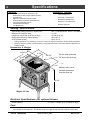
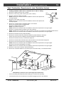
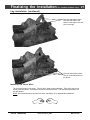
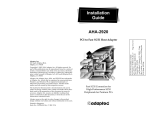
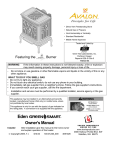
• Direct Vent Freestanding Stove
• Natural Gas or Propane
• Vent Horizontally or Vertically
• Standard Residential
• Mobile Home Approved
Tested and Listed by
Burner
Featuring the
OMNI-Test Laboratories, Inc.
Beaverton, Oregon
Report # 028-S-58-5
ANSI Z21.88
WARNING: If the information in these instructions is not followed exactly, a fire or explosion
may result causing property damage, personal injury or loss of life.
-
Do not store or use gasoline or other flammable vapors and liquids in the vicinity of this or
any other appliance.
WHAT TO DO IF YOU SMELL GAS
• Do not try to light any appliance.
• Do not touch any electrical switch; do not use any phone in your building.
• Immediately call gas supplier from a neighbor's phone. Follow the gas supplier's
instructions.
• If you cannot reach your gas supplier, call the fire department.
-
Installation and service must be performed by a qualified installer, service agency or the
gas supplier.
This appliance may be installed in an aftermarket permanently located, manufactured home
(USA only) or mobile home, where not prohibited by local codes.
This appliance is only for use with the type of gas indicated on the rating plate. This
appliance is not convertible for use with other gases unless a certified kit is used.
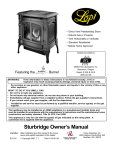
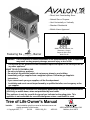
Tree of Life Owner's Manual
Installer:
After installation give this manual to the home-owner and
explain operation of this heater.
Copyright 2007, T.I.
$10.00
100-01169_001
4050119
4800 Harbour Pointe Blvd. SW
Mukilteo, WA 98275
Introduction
2
Introduction
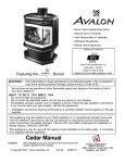
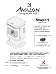
We welcome you as a new owner of an Avalon Tree of Life stove. In purchasing a Tree of Life you
have joined the growing ranks of concerned individuals whose selection of an energy system reflects
both a concern for the environment and aesthetics. The Tree of Life is one of the finest home heaters
the world over. This manual will explain the installation, operation, and maintenance of this stove.
Please familiarize yourself with the Owner's Manual before operating your heater and save the manual
for future reference. Included are helpful hints and suggestions that will make the operation and
maintenance of your new stove an easier and more enjoyable experience. We offer our continual
support and guidance to help you achieve the maximum benefit and enjoyment from your heater.
Important Information
No other Tree of Life Stove has the same serial number
as yours. The serial number is on the listing plate
chained to the gas control valve.
Register your warranty online at:
This serial number will be needed in case you require
service of any type.
Or, mail your warranty card to:
Model:
Avalon Tree of Life Stove
Serial Number:
Purchase Date:
Purchased From:
traviswarranty.com
Travis Industries House of Fire
4800 Harbour Pointe Blvd. SW
Mukilteo, WA 98275
Save Your Bill of Sale.
To receive full warranty coverage, you
will need to show evidence of the date
you purchased your heater. Do not
mail your Bill of Sale to us.
We suggest that you attach your Bill of
Sale to this page so that you will have
all the information you need in one
place should the need for service or
information occur.
Travis Industries
100-01169_001
4050119
Table of Contents
Introduction
3
Operation
Introduction & Important Information................2
Before You Begin .........................................28
Location of Controls .....................................28
Safety Precautions
Safety Precautions ......................................4
Features & Specifications
Starting The Pilot .........................................29
Starting the Stove for the First Time .................30
Turning the Stove On and Off .........................30
Features ....................................................6
Adjusting the Flame Height.............................30
Installation Options ......................................6
Adjusting the Blower Speed (optional) ..............31
Heating Specifications ..................................6
Normal Operating Sounds ..............................31
Dimensions.................................................6
Normal Operating Odors ................................31
Installation
Maintenance
Installation Warning......................................7
Maintaining Your Stove’s Appearance ..............32
Packing List................................................7
Yearly Service Procedure ..............................32
Additional Items Required for Installation ..........7
Troubleshooting Table...................................33
Installation Overview ....................................7
How this Stove Works ...................................34
Installation Hints..........................................8
What Turns the Main Burners On and Off......34
Stove Clearances ........................................8
Mobile Home Requirements ............................8
Heater Placement Requirements .....................9
What Prevents Gas Buildup.......................34
Wiring Diagram ............................................35
Replacement Parts List .................................35
Floor Protection Requirements........................9
Gas Line Installation.....................................10
Vent Requirements.......................................11
Approved Vent Configurations ........................12
Restrictor Position...................................12
Measuring Vent Lengths ...........................12
Vertical Term. with 0, 2, or 4 45° Elbows .......13
Hor. Term. with 1 90° Elbow........................14
Hor. Term. with 2 Elbows ...........................15
Hor. Term. with 3 Elbows ...........................16
Vertical Term. with 2 90° Elbows .................17
Vertical Term. with 3 Elbows......................18
Vent Termination Requirements ......................19
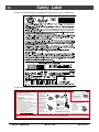
Safety Label
Safety (Listing) Label....................................36
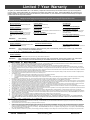
Warranty
Warranty ....................................................37
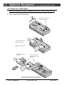
Optional Equipment
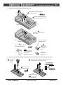
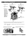
LP Conversion Kit ........................................38
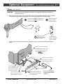
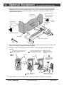
Blower .......................................................41
Accent Light ...............................................43
Index
Index.........................................................46
Class A Chimney Conversion..........................20
Masonry Chimney Conversion ........................21
Finalizing the Installation
Pilot Adjustment ..........................................22
Air Shutter Adjustment ..................................23
Glass Removal (& installation) ........................24
Log Installation............................................26
Travis Industries
100-01169_001
4050119
Safety Precautions
4
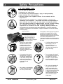
• IF YOU SMELL GAS:
*
*
*
*
*
Do not light any appliance
Extinguish any open flame
Do not touch any electrical switch or plug or unplug anything
Open windows and vacate building
Call gas supplier from neighbor's house, if not reached, call fire
department
•
This unit must be installed by a qualified installer to prevent the
possibility of an explosion. Your dealer will know the requirements in
your area and can inform you of those people considered qualified.
The room heater should be inspected before use and at least annually
by a qualified service person. More frequent cleaning may be
required due to excessive lint from carpeting, bedding material, etc.
•
The instructions in this manual must be strictly adhered to. Do not use makeshift
methods or compromise in the installation. Improper installation will void the warranty
and safety listing.
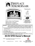
Look for this label:
•
For LPG only | Pout 11” W.C.
If the label is present, the
heater is equipped for LP
(propane). If the label is
absent, the heater is equipped
for NG (natural gas).
This heater is either approved for natural
gas (NG) or for propane (LP or LPG).
Burning the incorrect fuel will void the
warranty and safety listing and may cause
an extreme safety hazard. Direct
questions about the type of fuel used to
your dealer. Check for the label shown to
the right.
•
Contact your local building
officials to obtain a permit
and information on any
installation restrictions or
inspection requirements in
your area. Notify your
insurance company of this
heater as well.
• If the flame becomes sooty,
dark orange in color, or
extremely tall, do not
operate the heater. Call
your dealer and arrange for
proper servicing.
•
It is imperative that control
compartments, screens, or
circulating air passageways
of the heater be kept clean
and free of obstructions.
These areas provide the air
necessary for safe
operation.
• Do not operate the heater if
it is not operating properly in
any fashion or if you are
uncertain. Call your dealer
for a full explanation of your
heater and what to expect.
Ok
•
Gas
Travis Industries
Do not store or use gasoline
or other flammable liquids in
the vicinity of this heater.
?
A
AAAA
AAAA
100-01169_001
• Do not use this appliance if
any part has been under
water. Immediately call a
qualified service technician
to inspect the appliance and
to replace any part of the
control system and any gas
control which has been
under water.
4050119
Safety Precautions
•
A
5
AA
AA
AA
AA
A
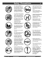
Do not place clothing or
other flammable items on or
near the heater. Because
this heater can be controlled
by a thermostat there is a
possibility of the heater
turning on and igniting any
items placed on or near it.
• Light the heater using the
built-in piezo igniter. Do not
use matches or any other
external device to light your
heater.
•
The viewing glass should be
opened only for lighting the
pilot or conducting service.
Do not operate with cracked,
broken, or removed glass.
instructions are given in this
manual. All other work must
be done by a trained
technician. Don't modify or
replace orifices.
•
Any safety screen or guard
removed for servicing must
be replaced prior to
operating the heater.
• Allow the heater to cool
before carrying out any
maintenance or cleaning.
•
Operate the heater
according to the instructions
included in this manual.
•
If the main burners do not
start correctly turn the gas
off at the gas control valve
and call your dealer for
service.
• The pilot flame must contact
the thermopile and
thermocouple (see the
illustration to the left). If it
does not, turn the gas
control valve to "OFF" and
call your dealer.
•
This unit is not for use with
solid fuel
•
Do not place anything inside
the firebox (except the
included fiber logs).
•
If the fiber logs become
damaged, replace with
Travis Industries log set.
•
Children and adults should
be alerted to the hazards of
high surface temperature
and should stay away to
avoid burns or clothing
ignition. Young children
should be supervised when
they are in the same room as
the heater.
•
Travis Industries
• Never remove, replace,
modify or substitute any part
of the heater unless
• Do not throw this manual
away. This manual has
important operating and
maintenance instructions
that you will need at a later
time. Always follow the
instructions in this manual.
This
Manual
Instruct everyone in the
house how to shut gas off to
the appliance and at the gas
main shutoff valve. The gas
main shutoff valve is usually
next to the gas meter or
propane tank and requires a
wrench to shut off.
100-01169_001
•
Plug the heater into a
120V grounded electrical
outlet. Do not remove the
grounding plug.
•
Don’t route the electrical
cord in front of, over, or
under the heater
• Travis Industries, Inc.
grants no warranty,
implied or stated, for
the installation or
maintenance of your
heater, and assumes
no responsibility of any
consequential
damage(s).
4050119
Specifications
6
Features:
-
Installation Options:
Ember Fyre™ Burner for "Wood Fire" Look
Works During Power Outages (millivolt system)
High Efficiency
Optional Thermostat or Remote Control
Optional Blower for Quicker Heat Distribution
Convenient Operating Controls
Variable-Rate Heat Output
Low Maintenance
-
Freestanding Stove
-
Horizontal or Vertical Vent
-
Residential or Mobile Home
-
Straight or Corner Placement
-
Bedroom Approved
Heating Specifications:
Approximate Heating Capacity (in square feet)*.....................500 - 1,500 with Blower, 500 to 1,200 Without
Maximum BTU Input Per Hour..............................................31,000
Output from Low to High (in BTU’s per hour).........................16,608 to 26,815
Steady State Efficiency (without blower)**............................Up to 86.5 %
AFUE (without blower) ........................................................Up to 72.8 %
*
**
Heating capacity will vary depending on the home’s floor plan, degree of insulation, and the outside temperature.
Efficiency rating is a product of thermal efficiency rating determined under continuous operation independent of
installed system.
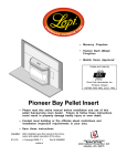
Dimensions & Weight:
18-3/8"
4-7/8"
The flue collar protrudes
26-3/4"
15-1/4"
7/8" above the stove top
NOTE:
Measure side, corner,
and back clearances
from the stove top.
28-3/4"
Weight: 215 Lbs.
Electrical Specifications (for optional blower)
Electrical Rating.........................................................115 Volts, 1.3 Amps, 60 Hz (150 watts on high)
Fuel:
This heater is shipped in natural gas (NG) configuration but may be converted to propane (LP) using
the included LP conversion kit. The sticker on top of the gas control valve will verify the correct fuel.
Travis Industries
100-01169_001
4050119
Installation (for qualified installers only)
7
Installation Warnings:
!
!
!
!
!
!
!
!
Failure to follow all of the requirements may result in property damage, bodily
injury, or even death.
This heater must be installed by a qualified installer who has gone through a
training program for the installation of direct vent gas appliances.
This appliance must be installed in accordance with all local codes, if any; if not,
follow ANSI Z223.1 and NFPA 54(88).
In Manufactured or Mobile Homes must conform with Manufactured Home
Construction and Safety Standard, Title 24 CFR, Part 3280, or, when such a
standard is not applicable, the Standard for Manufactured Home Installations,
ANSI/NCSBCS A225.1. This appliance may be installed in Manufactured Housing
only after the home is site located.
This stove is designed to operate on natural gas or propane (LP).
All exhaust gases must be vented outside the structure of the living-area.
Combustion air is drawn from outside the living-area structure.
Notify your insurance company before hooking up this stove.
The requirements listed below are divided into sections. All requirements must be
met simultaneously. The order of installation is not rigid – the qualified installer
should follow the procedure best suited for the installation.
Packing List
Additional Items Required
•
•
•
•
•
•
Propane Conversion Kit
Log Set
Glass Latch Tool (to un-latch glass frame)
Touch-Up Paint
Vent (see “Venting Requirements” for details)
Gas Line Equipment (shutoff valve, pipe, etc.)
Installation Overview
AAAAAAAAAAAAAAAAAAAA
AAAAAAAAAAAAAAAAAAAA
AAAAAAAAAAAAAAAAAAAA
AAAAAAAAAAAAAAAAAAAA
AAAAAAAAAAAAAAAAAAAA
AAAAAAAAAAAAAAAAAAAA
AAAAAAAAAAAAAAAAAAAA
AAAAAAAAAAAAAAAAAAAA
AAAAAAAAAAAAAAAAAAAA
AAAAAAAAAAAAAAAAAAAA
AAAAAAAAAAAAAAAAAAAA
AAAAAAAAAAAAAAAAAAAA
AAAAAAAAAAAAAAAAAAAA
AAAAAAAAAAAAAAAAAAAA
AA
AAAAAAAAAAAAAAAAAAAA
AAAAAAAAAAAAAAAAAAAA
AAA
A
AAAAAAAAAAAAAAAAAAAA
AAAAAAAAAAAAAAAAAAAA
AAA
AA
AAAAAAAAAAAAAAAAAAAA
AAA
AA
AAAAAAAAAAAAAAAAAAAA
AAAAAAAAAAAAAAAAAAAA
AAAAAAAAAAAAAAAAAAAA
AAA
AA
See
AAAAAAAAAAAAAAAAAAAA
AAA
AA
See "Vent AAAAAAAAAAAAAAAAAAAA
"Clearances"
AAAAAAAAAAAAAAAAAAAA
AAAAAAAAAAAAAAAAAAAA
AAA
AA
Requirements"
AAAAAAAAAAAAAAAAAAAA
AAAAAAAAAAAAAAAAAAAA
AAA
AA
AAAAAAAAAAAAAAAAAAAA
AAAAAAAAAAAAAAAAAAAA
AAA
AA
AAAAAAAAAAAAAAAAAAAA
AAAAAAAAAAAAAAAAAAAA
AAA
AA
AAAAAAAAAAAAAAAAAAAA
AAAAAAAAAAAAAAAAAAAA
AAA
AA
AAAAAAAAAAAAAAAAAAAA
AAAAAAAAAAAAAAAAAAAA
AAAAAAAAAAAAAAAAAAAA
AAAAAAAAAAAAAAAAAAAA
AAAAAAAAAAAAAAAAAAAA
AAAAAAAAAAAAAAAAAAAA
AAAAAAAAAAAAAAAAAAAA
AAAAAAAAAAAAAAAAAAAA
AAAAAAAAAAAAAAAAAAAA
AAAAAAAAAAAAAAAAAAAA
AAAAAAAAAAAAAAAAAAAA
AAAAAAAAAAAAAAAAAAAA
AAAAAAAAAAAAAAAAAAAA
See "Gas Line AAAAAAAAAAAAAAAAAAAA
AAAAAAAAAAAAAAAAAAAA
AAAAAAAAAAAAAAAAAAAA
Installation"
AAAAAAAAAAAAAAAAAAAA
AAAAAAAAAAAAAAAAAAAA
AAAAAAAAAAAAAAAAAA
AAAAAAAAAAAAAAAAAAAA
AAAAAAAAAAAAAAAAAAAA
AAAAAAAAAAAAAAAAAA
AAAAAAAAAAAAAAAAAAAA
AAAAAAAAAAAAAAAAAAAA
AAAAAAAAAAAAAAAAAA
AAAAAAAAAAAAAAAAAAAA
AAAAAAAAAAAAAAAAAAAA
AAAAAAAAAAAAAAAAAA
AAAAAAAAAAAAAAAAAAAA
AAAAAAAAAAAAAAAAAAAA
AAAAAAAAAAAAAAAAAA
AAAAAAAAAAAAAAAAAAAA
AAAAAAAAAAAAAAAAAAAA
AAAAAAAAAAAAAAAAAA
AAAAAAAAAAAAAAAAAAAA
AAAAAAAAAAAAAAAAAA
See "Floor
AAAAAAAAAAAAAAAAAA
Protection
AAAAAAAAAAAAAAAAAA
AAAAAAAAAAAAAAAAAA
Requirements"
AAAAAAAAAAAAAAAAAA
Travis Industries
100-01169_001
4050119
Installation
8
(for qualified installers only)
Installation Hints:
•
If converting to LP, convert the appliance prior to installation.
•
The blower is easiest to install prior to installation. Because the blower is located near the gas inlet
location, the gas inlet must be routing around the blower position.
•
Install the logs last - they are fragile.
•
When determining the location of the stove, locate the wall studs (for horizontal penetrations) and
ceiling trusses (for vertical penetrations). You may wish to adjust the stove position slightly to ensure
the vent does not intersect with a framing member.
•
Fumes and smoke from the paint curing and oil burning off the steel may occur the first time you start
this heater. This is normal. We recommend you open windows to vent the room.
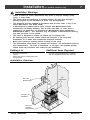
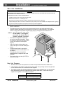
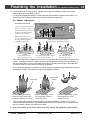
Stove Clearances
AAA
AAA
AAA
Straight Installations
Corner Installations
With this clearance the
vent is centered 7-1/8"
from the back wall, 23-1/2"
from the side wall.
With this clearance, the vent is
centered 15-3/4" from the
wall.
10" Min.
5" Min.
5" Min.
45°
Mobile Home Requirements
•
When the stove is installed in a mobile home, it must be bolted to the floor and the appliance
grounded (use the optional blower with a grounded circuit or other suitable grounding method current ANSI/NFPA 70).
Travis Industries
100-01169_001
4050119
Installation (for qualified installers only)
9
Heater Placement Requirements
•
Heater must be installed on a level surface capable of supporting the heater and vent.
•
Due to high temperatures, the appliance should be located out of traffic and away from furniture
and draperies.
•
When placed in a location where the floor to ceiling height is under 7 feet, the installation is
considered an alcove and must meet the following requirements:
•
The alcove floor to ceiling height must be at least 58” tall
•
The alcove must not be more than 45” deep before the ceiling returns to 7’
•
The alcove must be at least 46-3/4” wide
•
The heater must not be placed so the vents below or above the door, along the sides of heater, or
along the back of the heater can become blocked.
This heater may be placed in a bedroom. Please be aware of the large amount of heat this
appliance produces when determining a location.
•
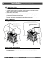
Floor Protection Requirements
•
When the stove is installed directly on carpeting, vinyl or other combustible material other
than wood flooring or a high pressure laminate wood floor, the stove must be installed on
a metal or wood protection panel extending the full width and depth of the heater
(Minimum 26-3/4” wide by 19” deep).
Make sure these rubber tipped bolts on each leg
contact the floor (they dampen any noise that may
transmit through the hearth). Do not adjust with
weight on the legs, the rubber tips may tear.
Travis Industries
100-01169_001
4050119
Installation
10
(for qualified installers only)
Gas Line Installation
MASSACHUSETTS INSTALLATIONS
-
WARNING:
THIS PRODUCT MUST BE INSTALLED BY A LICENSED PLUMBER OR GAS FITTER WHEN INSTALLED WITHIN THE
COMMONWEALTH OF MASSACHUSETTS.
OTHER MASSACHUSETTS CODE REQUIREMENTS:
•
Flexible connector must not be longer than 36 inches.
•
Shutoff valve must be a “T” handle gas cock.
•
Only direct vent sealed combustion products are approved for bedrooms or bathrooms.
•
Fireplace dampers must be removed or welded in the open position prior to the installation of a fireplace insert or gas log.
•
A carbon monoxide (CO) detector is required in the same room as the appliance.
!
The gas line must be installed in accordance with all local codes, if any; if not, follow current ANSI
Z223.1 or NFPA 54.
!
The heater and gas control valve must be disconnected from the gas supply piping during any
pressure testing of that system at test pressures in excess of 1/2 psig (3.45 kPA). For pressures
under 1/2 psig (3.45 kPA), isolate the gas supply piping by closing the manual shutoff valve.
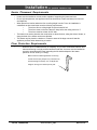
N O T E : The gas inlet may pass close
to the blower - we suggest
you install the blower first or
provide adequate clearance.
•
This heater is designed for natural gas
but can be converted to propane. Check
the sticker on top of the gas control valve
to verify the correct fuel is used (see
page 4).
•
Leak test all gas line joints and the gas
control valve prior to and after starting the
heater.
•
A manual shutoff valve is required for
installation (it must be located within 3’ of
the heater).
T-Handle gas cocks are required in
Massachusetts in compliance with code
248CMR.
•
The location of the gas inlet (3/8" FPT) is
shown to the right.
A
10-1/4"
C
te
en
rlin
e 5-3/4"
6-1/2"
Gas Inlet Pressure
•
With the heater off, the inlet pressure must meet the requirements listed in the table below
•
If the pressure is not sufficient, make sure the piping used is large enough and the total gas load
for the residence does not exceed the amount supplied.
•
The supply regulator (the regulator that attaches directly to the residence inlet or to the propane
tank) should supply gas at the suggested input pressure listed below. Contact the local gas
supplier if the regulator is at an improper pressure.
Natural Gas
Propane
Travis Industries
Standard Input Pressure
7” W.C. (1.74 Kpa)
13” W.C. (3.23 Kpa)
100-01169_001
4050119
Installation (for qualified installers only)
11
Vent Requirements
•
The vent must maintain the required 1" clearance to combustible materials to prevent a fire. Do not fill
air spaces with insulation.
•
The gas appliance and vent system must be vented directly to the outside of the building, and never
be attached to a chimney serving a separate solid fuel or gas-burning appliance. Each direct vent gas
appliance must use it's own separate vent system.
•
When the vent passes through a
wall a wall thimble is required.
When the vent passes through a
ceiling a support box or firestop is
required. When the vent passes
through the roof, a roof flashing
and storm collar are required.
Follow the instructions provided
with the vent for installing these
items.
Vertical Termination NOTE:
always use the "high-wind"
version (if applicable)
Vertical Vent
Requirements
Use a roof flashing and storm collar
whenever passing through the roof
Use a firestop whenever
passing through a ceiling
NOTE: Wall thimbles may have
different dimensions than what is
required by this heater.
•
•
•
Maintain a minimum 1"
clearance from vent to
any combustible
Use a support box
on exposed vent
Failure to adjust the air shutter properly
may lead to improper combustion
which can create a safety hazard.
Consult your dealer or installer if you
suspect an improperly adjusted air
shutter.
Use a thimble when
passing through a wall
This heater has been tested at
altitudes ranging from sea level to
8,000 feet (2,400 M). In this
testing we have found that the
heater, with its standard orifice,
burns correctly with just an air
shutter adjustment.
Horizontal Vent
Requirements
Minimum
Framing for wall
thimble
Maintain a minimum 1"
clearance from vent to any
combustible.
Horizontal Termination
Use of of the following 6-5/8" diameter co-axial gas direct vent systems:
Manuafacturer
Series
Simpson Dura-Vent
Model GS
Selkirk Hearth Products
Direct-Temp
American Metal Products
Ameri-Vent
N O T E: Always use the high-wind cap for the type of vent you are using (if applicable)
•
Slide the vent sections together and turn 1/4 turn until the sections lock in place.
•
Screws are not required to secure the vent. However, three screws may be used to
secure vent sections together if desired.
•
High temperature sealant is recommended at the appliance starter section connection
(use high-temperature silicone or Mill-Pac®).
•
If disassembly is required, at time of re-assembly check to see if the vent creates a tight fit.
If it does not, apply high temperature sealant to the joints of the affected sections.
•
Horizontal sections require a 1/4" rise every 12" of travel
•
Horizontal sections require non-combustible support every three feet (e.g.: plumbing
tape)
Travis Industries
100-01169_001
4050119
Installation
12
(for qualified installers only)
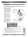
Approved Vent Configurations
Restrictor Position
•
A restrictor is built into
the appliance to
control the flow rate of
exhaust gases. This
ensures proper flames
for the wide variety of
vent configurations.
Depending upon the
vent configuration, you
may be required to
adjust the restrictor
position. The charts
for approved vent
configurations
describe which
position the vent
restrictor must be in.
To Adjust the Restrictor
b
a
Slide the restrictor
adjustment rod in.
c
Lift the cotter pin out.
NOTE:
The restrictor is
shipped in
position #1.
Restrictor
Positions
Replace the cotter pin
through the correct
hole on the restrictor
adjustment rod.
#1
#4
#5
#6
To Access the Restrictor
Use both hands to lift the stove
top off the stove.
#3
This restrictor is
in position # 6
#2
Measuring Vent Lengths
Vent Horizontal Run is
measured from the start of
the horizontal section to the
end of the termination.
Vent
Horizontal
Run
H2
Vent Height is calculated to
the top of the vent on
horizontal terminations and
to the top of the termination
on vertical terminations.
NOTE:
When a horizontal elbow (90° or 45°) is
used, horizontal length is the sum of the
two lengths (H1 + H2).
Horizontal
Elbow
Vent
Height
Travis Industries
Vertical Elbow
H1
Vertical Elbow
100-01169_001
4050119
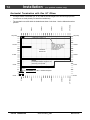
Installation (for qualified installers only)
13
40' (max)
24 ' (max)
20 feet
15 feet
10 feet
The termination must fall
within the shaded area
shown in the chart. Use
the indicated restrictor
position.
5 feet
•
0 feet
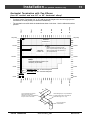
Vertical Termination with Zero, Two, or Four 45° Elbows
AAAAAAAAAAAAAAAAAAA
AAAAAAAAAAAAAAAAAAA
AAAAAAAAAAAAAAAAAAA
AAAAAAAAAAAAAAAAAAA
AAAAAAAAAAAAAAAAAAA
AAAAAAAAAAAAAAAAAAA
AAAAAAAAAAAAAAAAAAA
AAAAAAAAAAAAAAAAAAA
AAAAAAAAAAAAAAAAAAA
AAAAAAAAAAAAAAAAAAA
AAAAAAAAAAAAAAAAAAA
AAAAAAAAAAAAAAAAAAA
AAAAAAAAAAAAAAAAAAA
AAAAAAAAAAAAAAAAAAA
AAAAAAAAAAAAAAAAAAA
AAAAAAAAAAAAAAAAAAA
AAAAAAAAAAAAAAAAAAA
AAAAAAAAAAAAAAAAAAA
AAAAAAAAAAAAAAAAAAA
AAAAAAAAAAAAAAAAAAA
AAAAAAAAAAAAAAAAAAA
AAAAAAAAAAAAAAAAAAA
AAAAAAAAAAAAAAAAAAA
40' (max)
Restrictor
•
If using offsets, use the
table below to calculate the
vertical rise and horizontal
offset
Position # 6
35 feet
35 feet
NOTE:
Restrictor positions are based
upon lab tests. The ideal
Horizontal
Offset
30 feet
restrictor position may vary
30 feet
slightly, especially when the
Vertical
Rise
termination is near a
demarkation line.
Offset
Length
25 feet
25 feet
Restrictor
Position # 5
20 feet
1’
1’ 7”
1’ 9”
2’ 4”
3’ Section
2’ 5”
3’
4’ Section
3’ 2”
3’ 8”
4’ 4”
5’
4’ + 3’ Section 5’ 2”
5’ 9”
4’ + 4’ Section 6’
6’ 9”
Travis Industries
10 feet
5 feet
5 feet
0 feet
0 feet
0 feet
4’ + 1’ Section 3’ 9”
4’ + 2’ Section 4’ 6”
10 feet
15 feet
100-01169_001
24 ' (max)
1’ Section
2’ Section
15 feet
20 feet
1’
15 feet
Vert. Rise
5”
10 feet
Hor. Offset
None
5 feet
Offset Length
20 feet
4050119
Installation
14
(for qualified installers only)
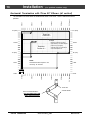
Horizontal Termination with One 90° Elbow
19' (max)
24 ' (max)
20 feet
15 feet
The termination must fall within the shaded area shown in the chart. Use the indicated restrictor
position.
10 feet
•
5 feet
If using a Snorkel Termination (14” or 36”) add the snorkel height to the vertical height (snorkel
terminations are used primarily for basement installations).
0 feet
•
AAAAAAAAAAAAAAAAAAAAA
AAAAAAAAAAAAAAAAAAAAA
AAAAAAAAAAAAAAAAAAAAA
AAAAAAAAAAAAAAAAAAAAA
AAAAAAAAAAAAAAAAAAAAA
AAAAAAAAAAAAAAAAAAAAA
AAAAAAAAAAAAAAAAAAAAA
AAAAAAAAAAAAAAAAAAAAA
AAAAAAAAAAAAAAAAAAAAA
AAAAAAAAAAAAAAAAAAAAA
AAAAAAAAAAAAAAAAAAAAA
AAAAAAAAAAAAAAAAAAAAA
19' (max)
Restrictor Position # 5
15 feet
NOTE:
Restrictor positions are based
upon lab tests. The ideal
restrictor position may vary
slightly, especially when the
termination is near a
demarkation line.
Restrictor
Position # 1
10 feet
15 feet
10 feet
NOTE:
Horizontal sections require a 1/4"
rise every 12" of travel.
5 feet
5 feet
NATURAL GAS: Min. 2' Section Required
PROPANE (LP): Min. 3' Section Required
Travis Industries
100-01169_001
24 ' (max)
20 feet
15 feet
10 feet
5 feet
0 feet
0 feet
0 feet
4050119
Installation (for qualified installers only)
15
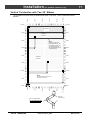
Horizontal Termination with Two Elbows
( one 90° vertical and one 90° or 45° horizontal elbow)
19' (max)
24 ' (max)
10 feet
20 feet
The termination must fall within the shaded area shown in the chart. Use the indicated restrictor
position.
15 feet
•
5 feet
If using a Snorkel Termination (14” or 36”) add the snorkel height to the vertical height (snorkel
terminations are used primarily for basement installations).
0 feet
•
AAAAAAAAAAAAAAAAAAAAA
AAAAAAAAAAAAAAAAAAAAA
AAAAAAAAAAAAAAAAAAAAA
AAAAAAAAAAAAAAAAAAAAA
AAAAAAAAAAAAAAAAAAAAA
AAAAAAAAAAAAAAAAAAAAA
AAAAAAAAAAAAAAAAAAAAA
AAAAAAAAAAAAAAAAAAAAA
AAAAAAAAAAAAAAAAAAAAA
AAAAAAAAAAAAAAAAAAAAA
AAAAAAAAAAAAAAAAAAAAA
AAAAAAAAAAAAAAAAAAAAA
19' (max)
Restrictor
Position # 5
15 feet
Restrictor
Position # 1
10 feet
NOTE:
Restrictor positions are based upon lab
tests. The ideal restrictor position may vary
slightly, especially when the termination is
near a demarkation line.
15 feet
10 feet
NOTE:
Horizontal sections require a 1/4"
rise every 12" of travel.
5 feet
5 feet
NATURAL GAS: Min. 2' Section Required
PROPANE (LP): Min. 3' Section Required
24 ' (max)
20 feet
15 feet
10 feet
5 feet
0 feet
0 feet
0 feet
H2
This is considered a horizontal
elbow (it does not matter
whether it turns right or left).
It may be a 90° or 45° elbow.
Horizontal length (max. 24') is calculated
by adding both lengths of horizontal run
(Horizontal Length = H1 + H2).
H1
Travis Industries
100-01169_001
This is considered a
vertical elbows
4050119
Installation
16
(for qualified installers only)
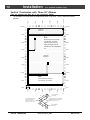
Horizontal Termination with Three 90° Elbows (all vertical)
21' (max)
24 ' (max)
20 feet
15 feet
5 feet
10 feet
The termination must fall within the shaded area shown in the chart. Use the indicated restrictor
position.
0 feet
•
AAAAAAAAAAAAAAAAAAAA
AAAAAAAAAAAAAAAAAAAA
AAAAAAAAAAAAAAAAAAAA
AAAAAAAAAAAAAAAAAAAA
AAAAAAAAAAAAAAAAAAAA
AAAAAAAAAAAAAAAAAAAA
AAAAAAAAAAAAAAAAAAAA
AAAAAAAAAAAAAAAAAAAA
AAAAAAAAAAAAAAAAAAAA
AAAAAAAAAAAAAAAAAAAA
21' (max)
Restrictor
Position # 5
15 feet
Restrictor
Position # 1
10' (min)
NOTE:
Restrictor positions are based
upon lab tests. The ideal restrictor
position may vary slightly,
especially when the termination is
near a demarkation line.
NOTE:
Horizontal sections require a 1/4"
rise every 12" of travel.
5 feet
15 feet
10' (min)
5 feet
This is a horizontal elbow NOT ALLOWED FOR THIS
VENT CONFIGURATION
Travis Industries
100-01169_001
24 ' (max)
20 feet
10 feet
5 feet
15 feet
0 feet
0 feet
0 feet
These are
vertical elbows.
4050119
Installation (for qualified installers only)
17
Vertical Termination with Two 90° Elbows
40' (max)
24 ' (max)
20 feet
5 feet
10 feet
15 feet
The termination must fall within the shaded area shown in the chart. Use the indicated restrictor
position.
0 feet
•
AAAAAAAAAAAAAAAAAA
AAAAAAAAAAAAAAAAAA
AAAAAAAAAAAAAAAAAA
AAAAAAAAAAAAAAAAAA
AAAAAAAAAAAAAAAAAA
AAAAAAAAAAAAAAAAAA
AAAAAAAAAAAAAAAAAA
AAAAAAAAAAAAAAAAAA
AAAAAAAAAAAAAAAAAA
AAAAAAAAAAAAAAAAAA
AAAAAAAAAAAAAAAAAA
AAAAAAAAAAAAAAAAAA
AAAAAAAAAAAAAAAAAA
AAAAAAAAAAAAAAAAAA
AAAAAAAAAAAAAAAAAA
AAAAAAAAAAAAAAAAAA
AAAAAAAAAAAAAAAAAA
AAAAAAAAAAAAAAAAAA
AAAAAAAAAAAAAAAAAA
AAAAAAAAAAAAAAAAAA
AAAAAAAAAAAAAAAAAA
AAAAAAAAAAAAAAAAAA
40' (max)
Restrictor
Position # 6
35 feet
35 feet
Restrictor
Position # 5
30 feet
25 feet
20 feet
NOTE:
Restrictor positions are
based upon lab tests. The
ideal restrictor position may
vary slightly, especially
when the termination is near
a demarkation line.
30 feet
25 feet
20 feet
Restrictor
Position # 1
15 feet
10' (min)
NOTE:
Horizontal sections require a 1/4"
rise every 12" of travel.
5 feet
15 feet
10' (min)
5 feet
24 ' (max)
20 feet
15 feet
10 feet
5 feet
0 feet
0 feet
0 feet
These are
vertical elbows.
This is a horizontal elbow NOT ALLOWED FOR THIS
VENT CONFIGURATION
Travis Industries
100-01169_001
4050119
Installation
18
(for qualified installers only)
Vertical Termination with Three 90° Elbows
(Two 90° Vertical and One 45° or 90° Horizontal Elbow)
40' (max)
24 ' (max)
15 feet
10 feet
5 feet
20 feet
The termination must fall within the shaded area shown in the chart. Use the indicated restrictor
position.
0 feet
•
AAAAAAAAAAAAAAAAAA
AAAAAAAAAAAAAAAAAA
AAAAAAAAAAAAAAAAAA
AAAAAAAAAAAAAAAAAA
AAAAAAAAAAAAAAAAAA
AAAAAAAAAAAAAAAAAA
AAAAAAAAAAAAAAAAAA
AAAAAAAAAAAAAAAAAA
AAAAAAAAAAAAAAAAAA
AAAAAAAAAAAAAAAAAA
AAAAAAAAAAAAAAAAAA
AAAAAAAAAAAAAAAAAA
AAAAAAAAAAAAAAAAAA
AAAAAAAAAAAAAAAAAA
AAAAAAAAAAAAAAAAAA
AAAAAAAAAAAAAAAAAA
AAAAAAAAAAAAAAAAAA
AAAAAAAAAAAAAAAAAA
AAAAAAAAAAAAAAAAAA
AAAAAAAAAAAAAAAAAA
AAAAAAAAAAAAAAAAAA
AAAAAAAAAAAAAAAAAA
40' (max)
Restrictor
Position # 5
35 feet
35 feet
NOTE:
Restrictor positions are based
upon lab tests. The ideal
30 feet
restrictor position may vary
slightly, especially when the
30 feet
termination is near a demarkation
line.
25 feet
20 feet
15 feet
10' (min)
Restrictor
Position # 1
25 feet
20 feet
15 feet
10' (min)
NOTE:
Horizontal sections require a
5 feet
5 feet
1/4" rise every 12" of travel.
H2
This is considered a horizontal
elbow (it does not matter
whether it turns right or left).
It may be a 45° or 90° elbow.
24 ' (max)
20 feet
This is considered a
vertical elbow
Horizontal length (max. 24') is calculated
by adding both lengths of horizontal run
(Horizontal Length = H1 + H2).
H1
Travis Industries
15 feet
10 feet
5 feet
0 feet
0 feet
0 feet
This is considered a
vertical elbow
100-01169_001
4050119
Installation (for qualified installers only)
19
Vent Termination Requirements (see illustration below)
!
Venting terminals shall not be recessed into a wall or siding.
A
Minimum 9" clearance from any door or window
B
Minimum 12" above any grade, veranda, porch, deck or balcony
C
Minimum 3-3/8" from outside corner walls
NOTE: Clearance in accordance with local installation codes and the requirements
of the gas supplier.
Roof
Surface
11” Min.
6” Min.
Roof
Eaves
D
Minimum 12" from inside corner walls
NOTE: Clearance in accordance with local installation codes and the requirements
of the gas supplier.
E
Minimum 11" clearance below unventilated soffits or roof surfaces
Minimum 18" clearance below ventilated soffits
Minimum 6" clearance below roof eaves
NOTE: Vinyl surfaces require 24"
NOTE: Clearance in accordance with local installation codes and the requirements of the gas supplier.
F
Minimum 12" clearance below a veranda, porch, deck or balcony
NOTE: Permitted only if veranda, porch, deck, or balcony is fully open on a minumum of two sides beneath the floor.
NOTE: Clearance in accordance with local installation codes and the requirements of the gas supplier.
G
Minimum 48" clearance from any adjacent building
H
Minimum 84" clearance above any grade when adjacent to public walkways or driveways
NOTE: may not be used over a walkway or driveway shared by an adjacent building
I
Minimum 48" clearance from any mechanical air supply inlet
J
Minimum 36" clearance above and 48” below and to the sides of non-mechanical air supply inlet
K
Minimum 36" from the area above the meter/regulator (vent outlet)
NOTE: Clearance in accordance with local installation codes and the requirements of the gas supplier.
L
Minimum 36" from the meter/regulator (vent outlet)
NOTE: Clearance in accordance with local installation codes and the requirements of the gas supplier.
M
Minimum 12” above the roof line (for vertical terminations)
N
Minimum 24” horizontal clearance to any surface (such as an exterior wall) – for vertical terminations
E
N
M
E
E
A
K
G
J
A
F
H
D
I
C
L
B
NOTE: Measure clearances to the nearest edge of the exhaust hood.
•
Use the vinyl siding standoff (#1250) when installing on an exterior with vinyl siding.
•
Vent termination must not be located where it will become plugged by snow or other material
Travis Industries
100-01169_001
4050119
Installation
20
(for qualified installers only)
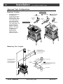
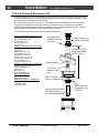
Class A Chimney Conversion Kit
!
!
Simpson Duravent provides a conversion kit for those wishing to use an existing wood stove chimney
to vent this direct vent stove. The illustration below gives an overview of this type of installation. See
the instructions included with the kit for details.
Do not exceed the maximum vertical rise. The restrictor position should be set to the position that
most closely resembles the vent configuration (see "Approved Vent Configurations" for details).
NOTE: because this installation utilizes non-standard vent, the restrictor position may vary. Carefully
monitor the burn characteristics to verify correct restrictor position.
The conversion kit does not work on interior masonry chimneys.
Chimney Conversion Kit A (# 931)
Metalbestos 6" I.D.
Security Chimneys 6" I.D.
Jackes-Evans 6" I.D.
Hart & Cooley 6" I.D.
Pro-Jet 6" I.D.
Chimney Conversion Kit B (# 932)
Simpson Dura-Vent 6" I.D.
Air-Jet 6" I.D.
Metal-Fab 6" and 7" I.D.
Amer. Metals 6" & 7" I.D.
Metalbestos 7" and 8" I.D.
Jackes-Evans 7" and 8" I.D.
Hart & Cooley 7" and 8" I.D.
Pro-Jet 7" and 8" I.D.
Security Chimneys 8" I.D.
Chimney Conversion Kit C (# 933)
Simpson Dura-Vent 7" and 8" I.D.
American Metals 8" I.D.
Air-Jet 8" I.D.
Metal-Fab 8" I.D.
American Metals 8" I.D.
Each Kit Contains:
Retro Connector
Retro Vertical Top
Additional Required Equipment:
4" Flex (#711 or U.L. 1777)
Termination (#991)
Co-Axial Sections
Screw the Retro
Vertical Top to the
Flex Pipe
Cut the Flex Pipe to
the chimney height
plus 3" (75 mm)
Type A Chimney
4" (100 mm)
Aluminum Flex
Pipe
Retro Connector
(screw to chimney)
Simpson Duravent Direct
Vent Pipe Sections
(use adjustable section)
Travis Industries
Retro Vertical Top
(screw to chimney)
100-01169_001
Screw the Retro
Connector to the
Flex Pipe
4050119
Installation (for qualified installers only)
21
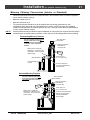
Masonry Chimney Conversions (Interior or Standard)
•
Follow the requirements and use the equipment listed in the illustration below to install this appliance
into an interior masonry chimney.
•
Maximum vertical rise is 40'
•
•
Minimum vertical rise is 10'
The restrictor position should be set to the position that most closely resembles the vent
configuration (see "Approved Vent Configurations" for details). NOTE: because this installation
utilizes non-standard vent, the restrictor position may vary. Carefully monitor the burn characteristics
to verify correct restrictor position.
Certain jurisdictions may not allow this type of installation or may require two co-linear vents be used for
venting through an existing masonry chimney. Check with your local building official before installing.
N O T E:
Freestanding Masonry Chimney
The entire chimney system must be
air-tight. Make sure to seal the
flashing, clean-out, and thimble
connection, and to inspect the
chimney.
A
A
AA
AAA
A
A
AA
A
A
AA
A
A
AA
A
A
A
AA
A
A
A
A A
AA
A
AA
A
A
AA
A
AAAAA
AAA
AA
A
Make sure the coaxial pipe
maintains a 1” clearance to any
combustible. The vent must be
sealed air-tight.
#990 90° Elbow
#991 High Wind
Termination
Flashing (included in
#934 Masonry
Conversion Kit
High-T
Silicoemp.
ne
4" Dia. Flex Line
(UL 1777 Gas Liner)
Co-Axial Straight
Lengths
Connector with Cover
(included in #934 Masonry
Conversion Kit)
Standard Masonry Fireplace
The entire chimney system must
be air-tight. Seal the connector
cover and inspect the chimney.
AAA
AA
AA
A
AAA
AA
A
AA
AA
A
A
AAA
AAA
A
AA
AA
AA
A
AAA
AAA
AA
AA
A
AA
A
AA
A
AA
AA
A
A
AA
AA
A
A
AA
A
A
AAAAA
AA
A
AA
A
AA
A
AA
AA
AAAAA
AA
A
AA
A
AA
A
AA
A
A
p.
-Tem
High icone
Sil
Make sure the coaxial pipe
maintains a 1” clearance to any
combustible. The vent must be
sealed air-tight.
Travis Industries
#991 High Wind
Termination
100-01169_001
Flashing (included in
#934 Masonry
Conversion Kit)
4" Dia. Flex Line
(UL 1777 Gas Liner)
Connector (included in #934
Masonry Conversion Kit)
secured and sealed to
block-off plate.
4050119
2 2 Finalizing
the Installation
(for qualified installers only)
Finalizing the Installation
!
Make sure the gas control valve is “OFF” and the heater is cool prior to conducting service.
1 Remove the face and glass (see page 24)
!
We recommend you purge the gas line at this time (with the glass removed). This allows gas to be
detected once it enters the firebox, ensuring gas does not build up.
2 Install the log set and coals (see page 26).
3 Turn on gas to the heater. Leak test all gas joints prior to starting the appliance. Start the pilot. Start
the main burner. Leak test all gas joints again.
4 Inspect the pilot flame (see the illustration below). Adjust the pilot flame if necessary.
Pilot Flame Adjustment
To adjust the pilot flame, turn this screw (NOTE: if totally
The pilot flame must contact the thermocouple and
unscrewed gas will come out of this port). Clockwise
lowers the flame while counter-clockwise raises it.
thermopile (see the illustration below). Adjust the pilot up or
Standard
Screwdriver
down as necessary.
5 Replace and secure the glass and face (see page 24)
Travis Industries
100-01169_001
4050119
Finalizing the Installation (for qualified installers only)
6
•
Let the heater burn for thirty minutes. Adjust the air shutter, if necessary, to achieve the correct
looking flame (see the illustration below).
The air shutter adjusts the amount of air that mixes with the gas before it exits the burner holes. It is
used to fine-tune the flame for differences in altitude and vent configuration.
Air Shutter Adjustment
ADJUSTING THE AIR SHUTTER
Gas Control Valve
Pushing to the left gives the flame less air
(making it more orange). Pushing to the
right gives the flame more air, making it
more blue. For fine adjustments use a
screwdriver to tap the air shutter.
Air Shutter Control
NOTE: If the air shutter is all the way
open, yet the flames remain sooty, shut
NOTE: The logs must be installed correctly to
off gas to the fireplace and contact a
monitor the flame while adjusting the air shutter.
qualified gas service technician.
Correct
Not Enough Air
Too Much Air
Flames should be blue at the
If the flames are over 14" tall or sooty on
If the flames are all blue and
base, yellow-orange on the top.
the ends, open the air shutter.
short, close the air shutter.
!
If the vent configuration is installed incorrectly the vent may cause the flames inside the heater to lift or
“ghost” – a dangerous situation. Inspect the flames after installation to insure proper performance. If
the vent configuration is correct, yet the flames are lifting or ghosting, shut off gas to the heater and
contact the dealer for information on remedying the problem.
!
Failure to properly adjust the air shutter may lead to improper combustion and a safety hazard. Consult
your dealer or installer if you suspect an improperly adjusted air shutter.
Burner Pan
The flames should burn right off
the top of the burner ports (if they
are too blue, adjust the air control).
Burner Ports
(holes)
If the flames are lifting, yet the
vent configuration is correct,
contact your dealer.
If the flames are ghosting, yet the
vent configuration is correct,
contact your dealer.
7
Turn the flame adjust knob to its highest position - the flames should be a maximum 9” to 10” tall.
Check the flame on low position. The flames should burn off of each burner hole. If the heater does
not work correctly, contact your dealer for a remedy.
8
Give this manual to the home owner and fully explain the operation of this heater.
Travis Industries
100-01169_001
4050119
23
2 4 Finalizing
the Installation
(for qualified installers only)
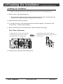
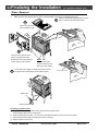
Glass Removal
!
Make sure the gas control valve is “OFF” and the heater is cool prior to conducting service.
c
a
Open the two latches holding the glass frame in
place - follow the directions shown below
Lift the stove top off the
stove and place it aside.
Top of
Firebox
Latch
Glass
b
Open the doors, lift them off the
hinges, and place them aside.
Remove the stove front by lifting it
up then forward. Place it aside.
d
NOTE:
The metal tabs on the
stove front slide over the
tabs on the side castings.
Lift the glass frame slightly, swing the top forward, then lift
the glass frame to disengage it from the bottom guides.
Catch (on glass frame)
Glass Frame
Glass Frame Guide
Re-Attaching the Glass Frame:
a) Slide the two brackets on the bottom of the glass frame into the glass frame
guides (hold the glass frame at a slight angle.
b) Swing the glass frame into place - you may have to lift it slightly to allow it to fit over the top of the firebox.
c) Attach the upper latches (follow the instructions above in reverse).
d) Replace the stove front and top.
Travis Industries
100-01169_001
4050119
Finalizing the Installation (for qualified installers only)
Glass Frame Removal and Installation (continued)
The latch can come loose from the latch assembly. This occurs only when it is rotated. Follow the
directions below to re-install the latch if it comes loose.
Hold the latch at an angle and insert it into the slot on the glass frame anchor.
Latch
NOTE: this slot may be at a
different angle than illustrated.
Top of
Firebox
Glass Frame
Anchor
Note how the washer on the latch fits behind the flange on the
glass frame anchor.
Once fully inserted, turn the latch until it is upright.
Travis Industries
100-01169_001
4050119
25
2 6 Finalizing
the Installation
(for qualified installers only)
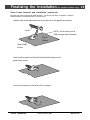
Log Installation
!
Make sure the gas control valve is “OFF” and the heater is cool prior to conducting service.
!
Failure to position the parts in accordance with these diagrams or failure to use only parts specifically
approved with this appliance may result in property damage or personal injury.
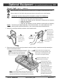
NOTE: The burner must be correctly positioned. Grasp the burner, lift it up,
position the gas inlet tube over the burner tube, and slide the
burner all the way down (see page 38 for details).
These steel platforms with
pins are for the rear log.
The pins are used to locate
the logs on the burner.
These flat spots are for the
front twigs.
Place the rear log in place as
shown here.
Place the front logs in place.
Note how the holes in the
bottom of the front logs fit
over the pins on the burner.
Travis Industries
100-01169_001
4050119
Finalizing the Installation (for qualified installers only)
27
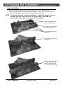
Log Installation (continued)
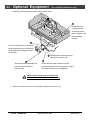
Place the top twigs in place.
Note how the holes in the
bottom of the twigs fit over the
pins on the logs.
Place the front twigs in place.
They fit on the flat portions of
the burner.
Installing the Rock Wool
The rock wool comes in one clump. Tear off “dime” sized clumps and flatten. Then pull on the wool to
create gauze-like pieces. Place them near some of the burner holes. The wool glows best when very
thin and porous.
NOTE: We recommend using very little rock wool, especially in LP or high-altitude installations.
AAAA
AAAAAA
AA
Travis Industries
100-01169_001
4050119
Operation
28
Before You Begin
Warning: Read this entire manual before you use your new stove (especially the section "Safety
Precautions" on pages 4 & 5). Failure to follow the instructions may result in property
damage, bodily injury, or even death.
Warning: Do not operate appliance with the glass front removed, cracked or broken. Replacement of the glass
should be done by a licensed or qualified service person.
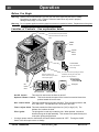
Location of Controls - See explanation below
The on/off switch and optional blower
control are located on the back of the
heater.
ON/OFF
Switch
ON
OFF
Optional
Blower
Control
The Pilot Flame
can be found below
the back log.
An instruction card for operating the heater
Swing the control cover
down to access the gas control
is attached near the gas control valve.
Replace it for easy reference.
valve and pilot igniter.
IGNITER
Pilot Igniter
Gas
Control
Valve
Gas Control Knob
On/Off Switch
This control is used to turn the flame on and off.
Optional Blower Control
Gas Control Knob
Flame Adjust Knob
This knob controls the speed of the internal convection blower that
pushes heated air into the room.
This knob controls gas to the stove and pilot. There are three positions: ON,
OFF, and PILOT. The indicator line is to the left of the knob.
Flame Adjust Knob This knob controls the flame height from low ("LO") to high ("HI”). The
indicator line is above the knob.
Pilot Igniter
•
The pilot igniter is used only to start the pilot. When pressed, it sends an
electrical charge to the pilot assembly. This creates a blue spark directly next
to the pilot, igniting the pilot flame.
If using a remote control or thermostat, the On/Off Switch must be left "OFF". Turning the On/Off
Switch "ON" will keep the stove on always.
Travis Industries
100-01169_001
4050119
Operation
29
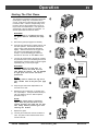
Starting The Pilot Flame
The pilot flame is required to ignite the main burners
(it also plays a safety role). It should be left on
once lit. It will stay lit unless the gas control valve
is turned to "OFF". However, the pilot will go out if
the gas is shut off, the propane tank runs out (or
low) or if the stove malfunctions. If the pilot turns
off frequently, call your dealer for information. To
start the pilot follow the directions below:
a
5 minutes
WARNING:
When lighting or re-lighting the pilot,
the glass must be removed (see page
24).
a
Remove the glass (see page 24 for details).
b
Push the gas control knob in slightly and turn it to
the "OFF" position. The knob will not turn from
"ON" to "OFF" unless the knob is depressed
slightly. Wait five minutes to let any gas that
may have accumulated inside the firebox
escape. If you smell leaking gas, follow the
directions on the cover "IF YOU SMELL GAS".
c
b
AA
AA
AA
AA
AA
PILOT
IGNITER
c
Turn the gas control knob to the "PILOT" position
and press the knob in, this will allow gas to flow to
the pilot light. Press the button on the pilot igniter
repeatedly until you see the pilot light.
WARNING:
If the pilot does not light after 15
seconds, release the knob and call
your dealer for service. Do not attempt
to light pilot until service has been
performed.
NOTE:
You may wish to remove the log set to
gain a better view of the pilot (see page
26).
d
Keep the gas control knob depressed for 30
seconds once it is lit.
e
Release the gas control knob. If the pilot goes
out, repeat step C. If the pilot refuses to stay lit,
call your dealer for service. With the pilot lit,
proceed to step “f”.
30 seconds
AA
AAA
AAA
d
?
e
f
NOTE:
If the gas control knob is turned to
“OFF” after the pilot has been lit for
several seconds, the knob will not turn.
This safety feature prevents gas from
entering the firebox.
f
Replace the glass.
g
Turn the gas control knob counter-clockwise to
"ON". The pilot is now lit and the heater can be
turned on and off.
Travis Industries
g
100-01169_001
4050119
Operation
30
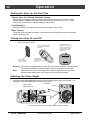
Starting the Stove for the First Time
Fumes from the Painted Surfaces Curing
Burn the heater at a medium setting for approximately one hour the first time. This will cure the
painted surfaces. Fumes from the paint curing and oil burning off the steel may occur. This is
normal. We recommend you open the window to vent the room.
Condensation
Water may appear on the glass each time you start the heater - this is normal.
Blue Flames
The flames will be blue when first started. After fifteen minutes the flames will turn a more realistic
yellow and orange color.
Turning the Stove On and Off
After the pilot has been started...
See the instructions included
with the remote for details on
operation.
°F
See the instructions
included with the
remote for changing
the battery.
Use this switch to
turn the main burner
on and off manually.
Au t
o
Ca Tim
nc e
el
Tim
Se e
t
OM
TE
OF MP
F
F
RO
OF
MI
N
SE
T
TE
MP
TIM
ER
°F
ON
For systems with wall
thermostats, use this switch to
control the temperature (right
is hotter, left cooler). Some
systems require the on/off
switch to be on.
Warning: Do not place combustible items on top or directly in front of the heater, even temporarily.
The optional thermostat may start the heater causing a combustible item to ignite.
Note:
If the heater turns on and off frequently while using the thermostat, you may want to
adjust the flame height down until it produces just enough heat needed.
Adjusting the Flame Height
+
Your stove has an adjustable flame to tailor the look and heat output to your specific needs. It is
adjusted by turning the middle dial on the gas control valve.
Flame Height
Adjustment Knob
Index Mark
Turn counter-clockwise to adjust the flame higher, clockwise to lower.
Travis Industries
100-01169_001
4050119
Operation
31
Adjusting the Blower Speed (optional)
The blower helps transfer heat from the heater into the room. It will not turn on until the heater is up to
temperature (approximately 10 minutes after starting). See the illustration below for instructions on
adjusting the blower speed.
OFF
LOW
HIGH
The high position is
all the way counterclockwise, without
clicking off.
Turn the dial all
the way counterclockwise until it
clicks off.
ON
ON
OFF
Turn the dial
all the way
clockwise.
ON
OFF
OFF
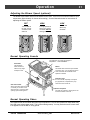
Normal Operating Sounds
The appliance may creak with change of
temperature -- THIS IS NORMAL.
Pilot Flame
The pilot flame,
which remains on,
makes a very slight
"whisper" sound.
Blower
This heater uses a blower to push heated
air into the room. You will hear the sound
of air movement that increases as the
speed is increased.
Extinction Pops
It is not unusual, especially on Propane
(LP) appliances, to experience a "pop"
when the burner is shut off.
Gas Control Valve
As the gas control valve is turned
on and off you will hear a dull
clicking sound. This is the valve
opening up and shutting down.
Blower Snap Disk
This part can produce a clicking sound as
it turns the blower on and off.
Normal Operating Odors
This appliance has several areas that reach high temperatures. Dust or other particles on these areas may
burn and create a burnt-paper smell. This is normal during startup. You may notice the smell is more acute
if the appliance was left idle for a long period.
Travis Industries
100-01169_001
4050119
Maintenance
32
(for qualified service personnel only)
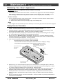
Maintaining Your Stove's Appearance
WARNING: Make sure the appliance has fully cooled prior to cleaning.
Painted Surfaces
•
Painted surfaces should be cleaned with a duster. If scratches occur, lightly sand the area with fine sandpaper.
Clean the area and, with the stove cool, apply one or two thin coats of stove paint to the area (mask the area to
avoid overspray). Allow the stove to dry, then turn the stove on to cure the paint (1 hour on medium).
Enamel Surfaces
•
Use only soft cloth and water to clean enamel surfaces. To fix chips in the enamel, follow the directions below:
1) Let the stove cool. Clean the area thoroughly.
2) Shake the Travis Enamel Touch-Up thoroughly. Apply to the damaged area.
Glass
•
Clean the glass with soap and water (do not use abrasives). To remove the glass, follow the instructions on page 24.
Yearly Service Procedure
•
Failure to inspect and maintain the heater may lead to improper combustion and a potentially dangerous
situation. We recommend the following procedures be done by a qualified technician.
1
Check the pilot flame. It should touch approximately 3/8" of the top of the thermopile and touch the top of the
thermocouple (see illustration below). If it does not, contact your dealer for service.
2
Shut off gas to the heater by turning the gas control knob to "OFF" (see step A under "Starting the Pilot" on page
29). Let the heater cool for 15 minutes. Remove the glass (see page 24).
3
Remove the log set (NOTE: the logs are very fragile - see page 26). If severely deteriorated, replace.
Check the logs for sooting. A small amount of soot along the bottom of the logs is normal. If excessive sooting
is found, the heater will require adjustment. Contact your dealer.
4
Clean the burner (especially the burner holes) and inspect the following:
•
•
Make sure the burner is not warped, cracked, or damaged.
Check the firebox and area around the pilot to make sure there is no warping or damage.
If any problem is found, discontinue use and contact your dealer for service.
Before Disassembly - Check the pilot flame.
It should touch the thermocouple and
Check the walls and ceiling
thermopile.
Thermopile
of the firebox for
deterioration.
Pilot Hood
Thermocouple
Check the burner holes.
Make sure the burner is not
warped or damaged.
5
Replace the log set. Clean and replace the glass (use non-abrasive cleaner - if damaged, replace). Make sure
the gasket along the perimeter of the glass contacts the face of the firebox and forms an air-tight seal. If it does
not, re-align or replace the gasket to insure an air-tight seal. Replace the glass.
6
Inspect the area behind the access door. Clean if necessary. Check the gas control valve and the gas lines. If
damage is found, discontinue use and contact your dealer for service. Clean the air channels and ducts.
7
Start the pilot and turn on the main burner. The flames should be orange/yellow and not touch the top of the
firebox. If the pilot or main burners do not burn correctly, contact your dealer for service. Monitor the blower
operation.
8
Remove any debris or vegetation near the vent termination. Contact your dealer if any sooting or deterioration is
found near the vent termination.
Travis Industries
100-01169_001
4050119
Maintenance
(for qualified service personnel only)
33
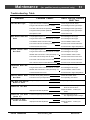
Troubleshooting Table
Problem:
Pilot Will Not Light
Main Burners Will Not
Start
Remote Control Does
Not Work
Thermostat Does Not
Work
Optional Blower Does
Not Work
Possible Cause:
Don't Call for Service
Until You:
A gas shut off valve is turned off
Check all gas shut off valves
The gas control knob isn't turned to "PILOT"
See "Starting the Pilot Light" Step C
The valve control knob isn't pushed in
See "Starting the Pilot Light" Step C
The igniter wasn't pressed repeatedly
See "Starting the Pilot Light" Step C
No Propane in Tank
Check Tank Level
The pilot light has gone out
See "Starting the Pilot Light"
The gas control valve is turned to "PILOT" or "OFF"
See "Starting the Pilot Light"
The ON/OFF switch is turned to "OFF"
Turn the ON/OFF switch to "ON"
The remote control is not working correctly
See the remote control instructions
The thermostat is set too low
Set thermostat to higher temperature
The pilot light has gone out
See "Starting the Pilot Light"
The gas control valve is turned to "PILOT" or "OFF"
See "Starting the Pilot Light"
ON/OFF switch is turned to "ON" (stove stays on)
Turn the ON/OFF switch to "OFF"
The remote is too far away from the stove
Use the remote closer to the stove
The remote control receiver is turned "Off"
See the remote control instructions
One of the two remote control batteries is dead
See the remote control instructions
The pilot light has gone out
See "Starting the Pilot Light"
The gas control valve is turned to "PILOT" or "OFF"
See "Starting the Pilot Light"
ON/OFF switch is turned to "ON" (stove stays on)
Turn the ON/OFF switch to "OFF"
The thermostat is set too low
Set thermostat to higher temperature
The stove is not getting electricity
Check the breaker switch
The stove is not up to temperature
See "Operating Your Stove"
Pilot Goes Out Once A The gas supply has been shut off
Month Or More
Keep the gas supply turned on
The stove has just been started
This is normal - see "Starting the
Stove for the First Time"
Improper air shutter adjustment
Adjust Air Shutter - contact your
dealer
Flames Are Too Short
(Under 6")
The flame height may be turned too low
Turn the flame height to "HI" See "Adjusting the Flame Height"
Thin Layer of Soot
Covers the Glass
The logs or coals are placed incorrectly
See "Log Set Installation & Removal"
Improper air shutter adjustment
Adjust Air Shutter - contact your
dealer
Flames Are Too Blue
Travis Industries
100-01169_001
4050119
Maintenance
34
(for qualified service personnel only)
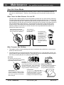
How this Stove Works
!
This stove was designed with safety as the primary concern. Many of the components inside this
stove are for safety purposes. Therefore, only certified gas service technicians should service this
stove.
What Turns the Main Burners On and Off
When heated, the thermopile
generates electricity (a very small
amount measured in "Millivolts").
This electricity is
used to operate the
main burners.
The main burners
are switched on and
off using the
electricity generated
by the thermopile.
The ON/OFF switch,
remote control, or
thermostat control
the circuit to the main
burner.
MAIN BURNER
This stove uses a millivolt system to control its operation (a millivolt is a very small amount of electricity).
The thermopile and thermocouple generate electricity when heated by the pilot flame. This electricity
is used to operate the gas valve. Without enough electricity, the gas valve will not turn on. That is why
when starting the pilot the gas control knob has to be pressed in long enough for the thermocouple to
heat up and generate enough electricity. The thermopile provides power for the ON/OFF switch,
remote control, or thermostat (see the illustration below). Because the thermopile generates the
electricity needed to turn the stove on and off, this stove can be operated when the power is out
(although the blower will not run).
ON
OFF
What Prevents Gas Buildup
+
This appliance utilizes a high-technology gas valve in conjunction with a pilot flame to ensure no gas
builds up inside the firebox.
+
The thermocouple (next to the pilot) senses when the pilot flame is lit. If the pilot flame goes out, this
thermocouple no longer generates electricity, causing the gas valve to automatically shut off all gas to
the heater, preventing the pilot from spilling gas into the firebox.
Pilot Flame
The pilot flame is a time-proven
component that eliminates the possibility
of gas buildup inside the firebox.
Gas Valve
This high-technology valve automatically
shuts off all gas if it does not receive a signal
from the thermocouple. If any component is
damaged or sensing a malfunction, or if the
wiring is damaged, it will shut off all gas.
Thermocouple
The thermocouple generates a small
amount of electricity. If the pilot flame
goes out, the gas valve automatically
shuts off all gas.
Travis Industries
External Shut Off Valve
This valve is placed on the gas line
to shut off gas to the appliance
during maintenance procedures.
Ceramic Glass
The glass in your heater is the most
durable glass available. It has been
tested to be extremely resistant to
breakage from temperature changes.
100-01169_001
4050119
Maintenance
35
(for qualified service personnel only)
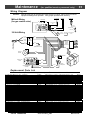
Wiring Diagram
Caution: Label all wires prior to disconnection when servicing controls. Wiring errors can cause
improper and dangerous operation. Verify proper operation after servicing.
Thermocouple
Millivolt Wiring
(for gas control valve)
Thermopile
Piezo Igniter
On/Off Switch
Red
AA
AA
Brown
Copper Co-Axial
Wire
Orange
Red
Spark Electrode
White
120 Volt Wiring
3
Black
Power In
Molex
Connector
Hot
(black)
Power Supply
Optional Remote
Control
Optional
Thermostat
Ground
(green)
Common
(white)
Pilot Hood
White
6
9
1
5
8
Ground
(attached to stove)
3
Remote
Control
Molex
Connector
2
Green
11
4
7
9
1
10
4
7
10
Optional
Blower
White
Black
Black
Rheostat
Black
1
Gas Control
Valve
Brown
2
4
3
5
7
Red
Black
Optional Regulator
Solenoid
6
8
Blower
Snap Disk
10
9
11
Blue
12
Black
Blue
Replacement Parts List
Caution:
Use only Travis Industries replacement parts. Do not use substitute materials.
BLOWER MNTNG BRKT ASS'Y, LEFT - G18/G22/G39
BLOWER MOUNT GRMT/SPACER (4)# - 1997+ PEL/1995+ GAS
BLOWER MOUNTING BRKT, G18/G22 - FAN KIT
BLOWER, CONV, G3/G7-10/G14- # - 16/G18/G21-26/P9-10 - PHD KIT
BURNER ASS'Y (EF), B38 LP/NG - TREE of LIFE
BURNER O-RING, #08, 3/16 id" - 5/16" od BERK/SHEFF SHELL KIT
BURNER O-RINGS, #20, 7/8" id - x 1" od - B15/B17/B18
CONV PARTS, LP - G18/22/G24- - G25('03) - EF BURNER/SIT(#175)
CONV PARTS, NG - G18/22/33/34 - SIT PILOT/VALVE
DOOR ASS'Y, LT - TOL CASHMERE
DOOR ASS'Y, LT - TOL MAJOLICA
DOOR ASS'Y, LT - TOL MET BLK
DOOR ASS'Y, LT - TOL VERDE MST
DOOR ASS'Y, RT - TOL CASHMERE
DOOR ASS'Y, RT - TOL MAJOLICA
DOOR ASS'Y, RT - TOL MET BLK
DOOR ASS'Y, RT - TOL VERDE MST
DOOR HNG S-ASS'Y, LT - TOL BLK - BLACK PAINTED
DOOR HNG S-ASS'Y, LT - TOL CSH - CASHMERE PAINTED
DOOR HNG S-ASS'Y, RT - TOL BLK - BLACK PAINTED
DOOR HNG S-ASS'Y, RT - TOL CSH - CASHMERE PAINTED
ENAMEL TOUCH-UP - CASHMERE - 15 ml BOTTLE
ENAMEL TOUCH-UP - MAJOLICA - 15 ml BOTTLE
ENAMEL TOUCH-UP - VERDE MIST - (GREEN) 15 ml BOTTLE
FACE HINGE LEAF, TOL - BLACK - BLACK PAINTED
FACE HINGE LEAF, TOL - CSHMRE - CASHMERE PAINTED
FLEX PIPE, 3/8"od x 12" BLK # - 13-1/8" WITH FITTINGS
FLUE STARTER SECT., G18/G22 - G22/G28 - 2.188" x 6.629" dia
GASKET, GLASS 15/16x54" 302-B - VARIOUS WOOD, PELLET & GAS
GLASS SPRING PIN ASSY, 2004+ - ALL UNITS w/GLASS FRAME ASS'Y
GLASS w/FRAME ASS'Y, G18 '05/ - G39
GLASS, SIDE w/GSKT - T.O.L. - SERVICE PART
HW PACK, BLOWER - G18/G22 - #164
HW PACK, LEG LVL BOLT, CAST # - 1/4-20 - FOUR w/RUBBER TIPS
Travis Industries
228-20001
93005017
99000201
98900755A
226-20049
100-05101
100-05102
93006503
225-10304
224-12025
224-12027
224-12023
224-12029
224-12026
224-12028
224-12024
224-12030
220-00140
220-00139
220-00142
220-00141
100-02409
100-02410
100-02411
220-00144
220-00143
100-05115
93006555
99900408
221-22220
224-21015
250-00216
98900489
98900415
INJECTOR, PILOT - LP (#35) # - (ORIFICE) USE w/SIT PILOT ONLY
INJECTOR, PILOT - NG (#62) # - (ORIFICE) USE w/SIT PILOT ONLY
KNOB (PLASTIC), RHEOSTATS # - BLACK W/GOLDLINE - GAS/WOOD
LOG EMBERS, ROCK WOOL #
LOG SET, LS22 - 8 PIECE# - T.O.L.
MAGNET w/SHEATH - 1.000 x .750" 1/4" THICK
MANUAL, TREE OF LIFE 2005
MIXING TUBE ASS'Y, G18/21-2/39 - w/B15/17/18/21/23/36/38 BURNER
ORIFICE, BURNER - .0625" # - 1.180" BRASS HEX (.0625 dia)
ORIFICE, BURNER - No. 37 # - 1.180" BRASS HEX (.104 dia)
PIEZO IGNITER, ALL GAS UNITS
PILOT ASS'Y, NG - S.I.T. # - COMPLETE
PILOT BAFFLE (BRK/PRA - 20 GA ALZ - 1.976 x 1.500
PILOT ELECTRODE, S.I.T. PILOT - ASSEMBLY
PILOT HOOD, S.I.T (REMVABLE) - REMOVEABLE - 2000
PILOT TUBE, S.I.T. PILOT ASSY - USE w/S.I.T. PILOT ONLY
POWER CORD, w/MOLEX CONNECTOR - (TERMINATED)
RHEOSTAT, RECTANGULAR - w/OFF - (WALL) w/NUT & WASHER
SIDE GLASS ASS'Y - T.O.L.
SNAP-DISC - 120deg NO # - NORMALLY OPEN
STOVE PACK, TOL - CASHMERE - #459
STOVE PACK, TOL - MAJOLICA - #458
STOVE PACK, TOL - MET BLACK - #457
STOVE PACK, TOL - VERDE MIST - #472
SWITCH, ON/OFF - SMALL, GAS # - 1996 & UP, ALSO 1995 DV
THERMO-COUPLE - S.I.T. # - USE w/S.I.T. PILOT ONLY
THERMO-GENERATOR - S.I.T. # - (THERMO-PILE) - S.I.T. PILOT
TOOL, KEY - DIE CAST ZINC - 1/4" x 3.75"
VALVE REGULATOR, LP SIT # - S.I.T. # 907.204
VALVE REGULATOR, NG SIT # - S.I.T. 907.201
VALVE, NG - S.I.T. (1.6-3.5) - S.I.T. # 820.704
WIRE HRNS, BLWR - G18/21/22/# - G39(OPT. BLOWER), G31 (MAIN 1)
WIRE HRNS, MAIN - G18/G22 # - Small gas units (NO SWITCH)
100-01169_001
100-05217
93006508
100-04111
93006053
172-00023
100-02802
100-01169
100-05401
100-05206
100-05204
100-05110
100-05403
210-05138
93006523
93006517
93006522
100-00260
100-00122
224-22025
100-00231
225-10459
225-10458
225-10457
225-10472
98900747
93006518
93006519
100-02314
100-05504
93006500
100-05508
100-00341
100-00367
4050119
Safety Label
36
A copy of the safety (listing) label (adhered to the back of the stove) is shown below.
A copy of the instruction label (on a tag near the gas control valve) is shown below.
LIGHTING INSTRUCTIONS
FOR YOUR SAFETY READ BEFORE LIGHTING
A. This appliance is equipped with an ignition device which must be lighted by hand.
When lighting the pilot, follow these instructions exactly.
B. BEFORE LIGHTING, smell all around the appliance area for gas. Be sure to smell next
to the floor because some gas is heavier than air and will settle on the floor.
WHAT TO DO IF YOU SMELL GAS:
• Do not try to light any appliance.
• Do not touch any electric switch; do not use any phone in your building.
• Immediately call your gas supplier from a neighbor's phone. Follow the gas
supplier's instructions.
• If you cannot reach your gas supplier, call the fire department.
C. Use only your hand to push in or turn the gas control knob. Never use tools. If the
knob will not push in or turn by hand, don't try to repair it, call a qualified service
technician. Force or attempted repair may result in a fire or explosion.
D. Do not use this appliance if any part has been under water. Immediately call a qualified
service technician to inspect the appliance and to replace any part of the control
system and any gas control which has been under water.
E. Do not block any control compartments, screens or circulating air passageways.
These areas provide air necessary for safe operation.
DO NOT REMOVE THIS INSTRUCTION PLATE
WARNING:
1. STOP! Read the safety information to the left and at the bottom
of this label before proceeding.
2. Set the thermostat to lowest
setting (if applicable).
7A
TO TURN OFF GAS TO APPLIANCE
1. Set the thermostat to lowest setting
(if applicable).
2. Turn off the blower (room air fan) on the
appliance.
3. Push the gas control knob in slightly and
turn it clockwise to the "OFF" position.
NOTE: The knob will not turn from "ON" to
"OFF" unless the knob is depressed slightly.
Do not force.
7B
4
3. Turn off the blower (room air fan)
on the appliance (if applicable).
4. Push the gas control knob in
slightly and turn it clockwise to
the "OFF" position.
7. A) Press the knob in and hold.
NOTE: The knob will not turn
from "ON" to "OFF" unless the
knob is depressed slightly. Do
not force.
5. Wait five (5) minutes to clear out
any gas. Then smell for gas,
including near the floor. If you
smell gas, STOP! Follow "B" in
the safety information to the left
on this label. If you don't smell
gas, go to the next step.
B) Immediately press the igniter
button repeatedly until the pilot is
lit. WARNING: If the pilot does
not light after 15 seconds, release
the knob and call your dealer
for service.
6
6. Turn gas control knob
counterclockwise to the "PILOT" position.
7C
C) Keep the gas control knob
depressed for 30 seconds once
the pilot is lit.
8. Release the gas control knob. If the pilot goes out, repeat step 7.
3
If the pilot will not stay lit after several tries, turn the gas control knob to
"OFF" and call your service technician or gas supplier.
9. Turn the gas control knob counterclockwise to "ON".
10. Turn on the blower (room air
fan) on the appliance.
9
11. Set the thermostat to desired
setting (if applicable) or use
the ON/OFF rocker switch or
remote control to operate the
main burner.
• If the knob does not pop up when released, stop and
immediately call your service technician or gas supplier.
IF YOU DO NOT FOLLOW THESE INSTRUCTIONS EXACTLY, A FIRE OR EXPLOSION MAY RESULT, CAUSING PROPERTY DAMAGE, PERSONAL
INJURY OR LOSS OF LIFE. WHEN LIGHTING OR RE-LIGHTING THE PILOT, THE DOOR MUST BE OPEN OR THE GLASS REMOVED. AFTER THE PILOT
IS LIT, CLOSE AND LATCH THE DOOR OR REPLACE THE GLASS BEFORE LIGHTING THE BURNER.
0330
Travis Industries
100-01169
4050119
Limited 7 Year Warranty
37
To register your TRAVIS INDUSTRIES, INC. 7 Year Warranty, complete the enclosed warranty card and mail it within ten (10) days of the appliance
purchase date to: TRAVIS INDUSTRIES, INC., 4800 Harbour Pointe Blvd. SW, Mukilteo, WA 98275. TRAVIS INDUSTRIES, INC. warrants this gas
appliance (appliance is defined as the equipment manufactured by Travis Industries, Inc.) to be defect-free in material and workmanship to the original
purchaser from the date of purchase as follows:
Check with your dealer in advance for any costs to you when arranging a warranty call.
Mileage or service charges are not covered by this warranty. This charge can vary from store to store.
Years 1 & 2 - COVERAGE: PARTS & LABOR
Burner Assembly:
Ceramic Glass
Accessories
Burner Pan, Mixing Tube, Air Shutter Assembly, Main
Burner Orifice
Glass (breakage from thermal shock)
Legs, Cast Firebacks
Firebox Assembly:
Ceramic Logs
Convection Heat Exchanger
Log Set, Coals, Ember Strip (Steel Fiber)
Adjustable Air Restrictor, Pressure Relief Mechanisms
(direct vents only), Glass Attachment Mechanism
Gas Control Assembly
Adjustable control valve, millivolt wiring and connectors
(located within the metal heater structure), thermopile,
thermocouple, pilot hood, orifices, pilot gas line, piezo
ignitor
Exclusions:
Gold Plating
Gold or Nickel Door, Optional Grill (see “Conditions and Exclusions” # 9)
Electrical Assembly:
Blower, wiring harness, snap discs, rheostat speed control
Re-Installation Allowance
In cases where heater must be removed from home for
repairs, a partial cost of re-installation is covered (preauthorization required)
One-Way Freight Allowance
One-way freight allowance on pre-authorized repair done at
factory is covered.
Paint, Gasketing
Years 3 THROUGH 5 - COVERAGE: PARTS & LABOR
Firebox Assembly:
Convection Heat Exchanger
Adjustable Air Restrictor, Pressure Relief Mechanisms (direct
vents only), Glass Attachment Mechanism
Exclusions:
One-Way Freight Allowance
One-way freight allowance on pre-authorized repair done at
factory is covered.
Paint, Gasketing, Burner Assembly, Electrical Assembly, Gas Control Assembly, Ceramic Glass, Ceramic Logs, Gold & Nickel
Plating, Accessories, Re-Installation Allowance
Years 6 & 7 - COVERAGE: PARTS ONLY
Firebox Assembly:
Adjustable Air Restrictor, Pressure Relief Mechanisms (direct vents only), Glass Attachment Mechanism
Exclusions:
Paint, Gasketing, Burner Assembly, Electrical Assembly, Gas Control Assembly, Ceramic Glass, Ceramic Logs, Gold & Nickel
Plating, Accessories, Convection Heat Exchanger, Re-Installation Allowance, One-Way Freight Allowance, Labor
CONDITIONS & EXCLUSIONS
1.
2.
3.
4.
5.
6.
7.
8.
9.
10.
11.
12.
13.
14.
15.
16.
17.
This new gas appliance must be installed by a qualified gas appliance technician. It must be installed, operated, and maintained at all times in accordance with the instructions in the Owner’s
Manual. Any alteration, willful abuse, accident, neglect, or misuse of the product shall nullify this warranty.
This warranty is nontransferable, and is made to the ORIGINAL purchaser, provided that the purchase was made through an authorized TRAVIS dealer.
Discoloration and some minor expansion, contraction, or movement of certain parts and resulting noise, is normal and not a defect and, therefore, not covered under warranty. The installer
must ensure the appliance is burning as per the rating tag at the time of installation. Over-firing (operation above the listed BTU rate) of this appliance can cause serious damage and will nullify
this warranty.
The warranty, as outlined within this document, does not apply to the chimney components or other Non-Travis accessories used in conjunction with the installation of this product. If in doubt as
to the extent of this warranty, contact your authorized TRAVIS retailer before installation.
Travis Industries will not be responsible for inadequate performance caused by environmental conditions such as nearby trees, buildings, roof tops, wind, hills or mountains or negative pressure
or other influences from mechanical systems such as furnaces, fans, clothes dryers, etc.
This Warranty is void if:
a.
The unit has been operated in atmospheres contaminated by chlorine, fluorine or other damaging chemicals.
b.
The unit is subject to submersion in water or prolonged periods of dampness or condensation.
c.
Any damage to the unit, combustion chamber, heat exchanger or other components due to water, or weather damage which is the result of, but not limited to, improper chimney/venting
installation.
Exclusions to this 7 Year Warranty include: injury, loss of use, damage, failure to function due to accident, negligence, misuse, improper installation, alteration or adjustment of the
manufacturer's settings of components, lack of proper and regular maintenance, damage incurred while the appliance is in transit, alteration, or act of God.
This 7 Year warranty excludes damage caused by normal wear and tear, such as paint discoloration or chipping, worn or torn gasketing, corroded or cracked logs, embers, etc. Also excluded is
damage to the unit caused by abuse, improper installation, modification of the unit, drilling of the orifices, or the use of fuel other than that for which the unit is configured. Units are shipped for
natural gas and must be converted to propane using the included conversion kit. Confirm fuel configuration with your installer.
Damage to gold, nickel, or brass surfaces caused by fingerprints, scratches, melted items, or other external sources left on the surface is not covered in this warranty. Damage from the use
of cleaners other than denatured alcohol on gold or nickel is not covered in this warranty. Damage from the use of abrasive cleaners on brass is not covered in this warranty.
TRAVIS INDUSTRIES, INC. is free of liability for any damages caused by the appliance, as well as inconvenience expenses and materials. Incidental or consequential damages are not covered
by this warranty. In some states, the exclusion of incidental or consequential damage may not apply.
This warranty does not cover any loss or damage incurred by the use or removal of any component or apparatus to or from the gas appliance without the express written permission of TRAVIS
INDUSTRIES, INC. and bearing a TRAVIS INDUSTRIES, INC. label of approval.
Any statement or representation of TRAVIS products and their performance contained in TRAVIS advertising, packaging literature, or printed material is not part of this 7 year warranty.
This warranty is automatically voided if the appliance’s serial number has been removed or altered in any way. If the appliance is used for commercial purposes, it is excluded from this warranty.
No dealer, distributor, or similar person has the authority to represent or warrant TRAVIS products beyond the terms contained within this warranty. TRAVIS INDUSTRIES, INC. assumes no
liability for such warranties or representations.
Travis Industries will not cover the cost of the removal or re-installation of hearths, facing, mantels, venting or other components.
If for any reason any section of this warranty is declared invalid, the balance of the warranty remains in effect and all other clauses shall remain in effect.
THIS 7 YEAR WARRANTY IS THE ONLY WARRANTY SUPPLIED BY TRAVIS INDUSTRIES, INC., THE MANUFACTURER OF THE APPLIANCE. ALL OTHER WARRANTIES,
WHETHER EXPRESS OR IMPLIED, ARE HEREBY EXPRESSLY DISCLAIMED AND PURCHASER’S RECOURSE IS EXPRESSLY LIMITED TO THE WARRANTIES SET FORTH
HEREIN.
IF WARRANTY SERVICE IS NEEDED:
1.
2.
3.
4.
If you discover a problem that you believe is covered by this warranty, you MUST REPORT it to your TRAVIS dealer WITHIN 30 DAYS, giving them proof of purchase, the purchase date,
and the model name and serial number.
Travis Industries has the option of either repairing or replacing the defective component.
If your dealer is unable to repair your appliance’s defect, he may process a warranty claim through TRAVIS INDUSTRIES, INC., including the name of the dealership where you purchased the
appliance, a copy of your receipt showing the date of the appliance’s purchase, and the serial number on your appliance. At that time, you may be asked to ship your appliance, freight charges
prepaid, to TRAVIS INDUSTRIES, INC. TRAVIS INDUSTRIES, INC., at its option, will repair or replace, free of charge, your TRAVIS appliance if it is found to be defective in material or
workmanship within the time frame stated within this 7 year warranty. TRAVIS INDUSTRIES, INC. will return your appliance, freight charges (years 1 to 5) prepaid by TRAVIS INDUSTRIES,
INC., to your regional distributor, or dealership.
Check with your dealer in advance for any costs to you when arranging a warranty call. Mileage or service charges are not covered by this warranty. This charge can vary from store to store.
Travis Industries
100-01169_001
4050119
Optional Equipment
38
(for qualified installers only)
LP Conversion Instructions
Install the conversion kit prior to installing the gas line to ensure proper gas use.
1
Remove the face and glass (see page 24). Remove the logs and coals (if installed - page 26)
2
Remove the burner (see illustration below).
Remove the ember trays from
both sides of the burner.
AA
AA
AA
AA
AA
AA
AA
Reach into the firebox and
lift the burner upwards.
Do not lift burner out by the
pins.
Pull the burner forward, out
of the firebox.
This tube on the burner
inserts into this tube on the
mixing tube.
A
AA
AAA
When Installing, make sure the burner is fully seated - it
rests on these supports. Replace the ember trays last.
Travis Industries
100-01169_001
4050119
Optional Equipment
3
(for qualified installers only)
39
Follow the directions below to replace the orifice.
Remove the four screws holding the
mixing tube in place.
a
1/4" Nutdriver
AA
AA
AA
AA
b Remove the mixing tube from the
air shutter by sliding it to the left.
Air Shutter
c
Slide the air shutter to the fully
open position.
AA
AA
AA
Burner Orifice
The new LP orifice has
“.062” stamped on it.
Manifold
d
e
5/16”
4
37
1/2" Wrench
NOTE:
Screw the LP orifice in
so the orifice shoulder
protrudes 5/16”
(indicating full insertion).
.06
2
Use a 1/2” open end wrench to
unscrew the burner orifice.
Apply thread
sealant to the
new orifice and
install.
The old NG
orifice has “37”
stamped on it.
Remove the pilot orifice following the instructions below. Replace with the propane pilot orifice
a
Lift the pilot hood
c
Remove the orifice and replace with the LP orifice. Screw the
orifice all the way in and replace the pilot hood.
off the pilot
assembly.
Orifice Identification:
LP (Propane) Orifice
b
Use a hex wrench to
unscrew the orifice.
35
35
NG (Natural Gas) Orifice
62
5/32" Hex
NOTE: when re-attaching,
this pin lines up with the
notch in the pilot hood.
Travis Industries
100-01169_001
4050119
Optional Equipment
40
(for qualified installers only)
a
5
Install the logs and
embers.
6
Replace glass and
face.
7
Remove the
regulator from the
front of the gas
control valve.
Replace with the
propane regulator,
using the new
gasket and screws
included with the
regulator. NOTE:
Leak test this
area after the
heater is
installed, gas is
connected,
and the main
burner is lit.
8
c
Remove and discard the three screws using a
slotted screwdriver of Torx T-20.
Install the LP regulator. Use the screws
included with the LP regulator. Tighten to
approximately 25 Lbs. torque.
b
Remove and discard the
regulator, diaphram, spring
and center post.
NOTE: Make sure the
regulator gasket is correctly
aligned before installation.
Slotted
Screwdriver
(or T-20 Torx)
Slotted
Screwdriver
(or T-20 Torx)
d
Place the LP label on top of
the control cover near the gas
control valve.
Make the gas line connection, bleed the gas line (if applicable), start the heater and thoroughly leaktest all gas connections and the gas control valve. Check the pilot. Adjust if necessary.
WARNING:
When lighting or re-lighting the pilot, the glass must be removed (see
page 24).
To adjust the pilot flame, turn this screw (NOTE: if totally
The pilot flame must contact the thermocouple and
unscrewed gas will come out of this port). Clockwise
lowers the flame while counter-clockwise raises it.
Travis Industries
thermopile (see the illustration below). Adjust the pilot up or
Standard
Screwdriver
down as necessary.
100-01169_001
4050119
Optional Equipment
Blower
41
(SKU 99000153)
WARNING:
1
(for qualified installers only)
Turn the gas control valve to off and make sure the appliance has fully cooled prior to
conducting service.
Attach the two black wires at the rear right of the stove to the thermodisk (orientation does not matter).
Then attach the thermodisk to the bottom of the stove body following the directions below.
a
ve
f
ko
Remove the snap disk cover plate below
the burner on the left side (when facing
the stove from the front).
b
Attach the snap disk
using the screws
removed in step "a".
Sto
c
Ba
Attach the wires
labeled snap disk to
the snap disk.
c
2
Snap Disk Wires
(Black - orientation
does not matter)
Place the blower near the rear of the stove. Attach the wiring in grommets following the directions
below.
Remove one of the screws holding
a
the mounting bracket in place. Insert
the screw through the eyelet on the
green ground wire and replace.
of
ck
a
B
ve
o
t
S
1/4" Nutdriver
b
Attach the black and white wires
labeled “Blower” to the blower
(orientation does not matter).
f
Route the wires labeled “Valve
on/off” and “Solenoid” under
c Attach the molex connector.
the burner pan to a location
near the gas control valve.
e
Attach the two wires leading
Slide the rubber grommets (with
DO NOT PLUG THE STOVE
from the control box to the two
spacers inserted inside) onto the
IN UNTIL INSTALLATION IS
block wires labeled “Rheostat”.
fan mounting bracket.
COMPLETE.
Travis Industries
d
100-01169_001
4050119
Optional Equipment
42
3
(for qualified installers only)
Slide the left side of the blower mounting bracket over the grommets on the left mounting bracket
attached to the stove (see the illustration below). Then insert the stud plate through the right side
grommets and through the right mounting bracket on the stove. Secure the stud plate with the
included washers and nuts
Make sure the bracket
Left Mounting
slides into the groove on
Bracket (on stove)
the rubber grommets.
Rubber
Right Mounting
of
k
c
Ba ve
Sto
Bracket (on stove)
Stud Plate
Blower Mounting
Grommet
Bracket
Blower Mounting Bracket
Stud Plate
Blower Mounting Bracket
11/32”
Socket
Washer
Nut
4
Make sure all of the wiring is placed away from the blower impeller and the bottom of the burner. Use
lock ties, if necessary, to ensure no wires are damaged.
5
Open the control cover following the directions below. Remove the button plug and install the
rheostat.
a
Loosen the two screws holding the control
box in place. This allows access to the
back of the control box.
c
Attach the rheostat wires to the two
quick connects inside the control
box (orientation does not matter).
NOTE: make sure the
fiberglass heat shield is in
place when re-attaching the
control box.
Control Box
Phillips
Screwdriver
e
Rheostat
Attach the rheostat to
the control panel with
the included nut and
star washer.
1/2"
Wrench
Back of
Stove
Attach
the knob.
b
6
Remove the button plug
from the control box.
NOTE: this tab fits into the
hole on the mounting bracket.
Plug the blower in. Let the heater achieve operating temperature and test blower operation.
Travis Industries
100-01169_001
4050119
Optional Equipment
Accent Light
(for qualified installers only)
43
(Type 2 – 94400111)
Make sure power to the heater has been turned off prior to installation (unplug the power cord).
Do not connect 110-120 VAC to the gas control valve or the on/off circuit on this fireplace.
IMPORTANT INSTALLATION NOTE FOR MODELS USING THE FIREBACKS:
N O T E:
1
Follow the steps below if installing the firebacks with an accent light.
• Remove the burner (see the manual for details).
• Install the rear fireback (see the instructions included with the firebacks).
• Install the accent light.
• Replace the burner.
• Install the side firebacks (see the directions included with the firebacks).
The bulb may be shipped separately. Do not touch the bulb – oil or other residue left on the
bulb may lead to premature bulb failure. Use a cloth or paper towel to handle the bulb.
Modify the accent light assembly as shown in the illustration below.
c
Remove the screw
that holds the accent
light bracket in place.
Re-attach it in the
a
Loosen these nuts
and slide the light
b
second hole from the
Re-attach the
top. This lowers the
accent light for proper
receptacle to the
receptacle out (take
light placement.
opposite side.
care to not touch the
Bend this tab upwards
halogen bulb)
to a 90° angle.
Accent Light Bracket
2
Remove the burner from the stove (see owner’s manual for details). Install the accent light assembly as
shown in the illustration below.
a Remove this screw on the firebox floor.
Position the accent light assembly in the
same location, and re-attach the screw
to secure the accent light assembly.
NOTE: To prevent heat-damage to the wires,
make sure this wires are routed along the
floor of the firebox, away from the burner.
A
AA
A
AA
b
AAAAA
AAAAA
AAAAA
NOTE: The accent light requires the right side access hole. If
this hole is being used for the thermodisk for optional blower,
switch the thermodisk to the mounting position on the left side.
Travis Industries
100-01169_001
Remove and discard the cover
plate (accessed from below).
c
Route the wires from the
accent light through gasket
and hole. Attach the accent
light cover plate (with
grommet) to the firebox floor
with the screws removed in
step “b”. Pull the excess
wire through the grommet,
towards the front of the stove
(this helps prevent the wire
from contacting the burner).
4050119
Optional Equipment
44
3
(for qualified installers only)
Attach the rheostat assembly following the directions below.
AA
AA
AA
AAA
c
Attach the quickconnect from the
accent light to the
quick-connect on the
rheostat wiring
harness.
d
Use the included wire nut to connect
the wire leading from the rheostat to
the remaining wire leading from the
accent light.
a Disconnect the molex connector
leading to the power cord.
e
Slide the rheostat assembly into
place and secure with the
included nuts.
b
Attach the two molex connectors on the
rheostat wiring harness to the power cord and
the molex connector on the appliance.
Make sure all wiring does not contact the
firebox or blower (use wireties if necessary).
4
Restore the firebox to the correct configuration (replace the burners, etc.).
Travis Industries
100-01169_001
4050119
Optional Equipment
(for qualified installers only)
45
Accent Light Operation
OFF
LOW
HIGH
Turn the dial all the
Turn the dial 180°
The high position
way counter-clockwise
clockwise until the light
is all the way
until it clicks off.
begins to glow.
clockwise.
N O T E: The accent light responds best when turned to high, then turned down to the desired light level.
Bulb Replacement
N O T E:
Do not touch the bulb – oil or other residue left on the bulb may lead to premature bulb
failure. Use a cloth or paper towel to handle the bulb.
The accent light must be replaced with 35 Watt 120 Volt T4 Halogen Bulbs (G6.35 Base) – available at
most hardware stores. To replace the bulb, simply remove it from the socket and insert the new bulb
(pin orientation does not matter).
Travis Industries
100-01169_001
4050119
Index
46
Accent Light.....................................................43
Installation Options ...........................................6
Adjusting the Blower Speed..............................31
Items Required for Installation............................7
Adjusting the Flame Height ...............................30
Leaking Gas .............................See Inst. on Cover
Air Shutter Adjustment......................................23
Listing Information ............................................36
Altitude Considerations.....................................10
Location of Controls..........................................28
Approved Vent Configurations..........................13-18 Log Set Installation and Removal .......................26
Blower Control..................................................31
Maintenance ....................................................32
BTU Input.........................................................6
Noise (see Normal Operating Sounds) ...............31
BTU Output......................................................6
Normal Operating Sounds.................................31
Cap (see vent termination).................................19
Packing List......................................................7
Chimney Cap (see vent termination)...................19
Pilot Flame Inspection.......................................22
Clearances.......................................................8
Piping Installation (see Gas Line Install)...............10
Condensation on Glass.....................................30
Restrictor Position ............................................12
Corner Installation.............................................8
Safety Label.....................................................36
Dimensions......................................................6
Safety Precautions ...........................................4
Elbows.............................................................12
Starting The Pilot..............................................29
Face Removal...................................................24
Starting the Stove for the First Time ...................30
Finalizing the Installation....................................22
Thermostat Operation.......................................30
Floor Protection ...............................................9
Turning the Stove On and Off............................30
Fuel.................................................................4
Vent Length (see “Vent Config.”)......................12
Gas Control Valve (Location)..............................28
Vent Requirements ..........................................11
Gas Inlet Pressure.............................................10
Vertical Vent Termination Requirements ............19
Gas Line Connection ........................................10
Warnings..........................................................4
Gas Line Install..................................................10
Warranty...........................................................37
Gas Smell.................................See Inst. on Cover
Water on Glass (see Condensation) ...................30
Glass Installation and Removal ...........................24
Weight.............................................................6
Hearth Requirements........................................9
What Prevents Gas Buildup...............................34
Heating Specifications ......................................6
What Turns the Main Burners On and Off............34
Horizontal Vent Termination Requirements ........19
Wiring Diagram..................................................35
How this Stove Works .......................................34
Yearly Service Procedure..................................32
Travis Industries
100-01169_001
4050119