1
Thank you for purchasing the LCD Control Terminal ZM-300 series. Please read the instruction
manual carefully, and operate the product with full understanding of its functions and operation
methods.
For the details of each LCD Control Terminal functions or the panel editing methods, please refer to
the instruction manual for the screen edit software.
Note
To make image data for ZM-300 series, use ZM-71S ver.2.0.0.0 or a newer version.
(When using ZM-373TA/371TL/373TL, ZM-383S/383SA, use version 2.1.0.0 or a
newer version.)
- ZM-71SE
Instruction Manual (Function)
User's Manualt (Operation)
Classification of ZM-300 series
In this user’s manual, ZM-300 series are referred as follows.
Expression in this
LCD Control Terminal model name
manual(series name)
ZM-350 ZM-352D
ZM-360 ZM-362S, ZM-362SA
ZM-371T, ZM-371TA, ZM-371S, ZM-371SA, ZM-371TL
ZM-370
ZM-372T, ZM-372TA, ZM-372S, ZM-372SA
ZM-300
ZM-373TA, ZM-373TL
ZM-381S, ZM-381SA
ZM-380 ZM-382S, ZM-382SA
ZM-383S, ZM-383SA
Precautions
When you plan to use SHARP LCD Control Terminal (hereafter referred to as
"ZMs"), you are requested to design each system so that even if a fault or
malfunction occurs within the ZM, it will not lead to a serious accident in your
system. You should incorporate back-up measures and fail-safe features in your
system that will thoroughly protect your system from malfunctions if a fault or
error occurs in the ZM.
SHARP ZMs are designed and manufactured with the idea that they will be used
in general applications in ordinary industries. Therefore, they must not be used in
specific applications that can affect the health or safety of the public, such as
nuclear power plants and other power generating plants. Such applications
require a special warranty of quality that SHARP explicitly does NOT offer for
these ZMs. However, if a user will certify that he/she does not requires a special
quality warranty on the ZM, and will limit the use of the ZM to non critical areas of
these applications, SHARP will agree to such use.
If you are planning to use SHARP ZMs for applications that may affect the lives
of human beings and property, and you need particularly high reliability
performance, such as in the fields of aviation, medicine, transportation,
combustion and fuel processing equipment, passenger cars, amusement park
rides, and safety equipment, please contact our sales division so that we can
confirm the required specifications.
Note
We have created this instruction manual carefully, but in case you have some
doubts or comments on this manual, please contact the affiliated store where
you bought this product or directly to our company.
It is forbidden to copy the content materials of this book, neither partially nor fully.
Please understand that the content of this manual may be altered for
amelioration without any notifications.
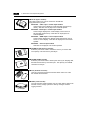
Safety Precautions
Read this user’s manual and attached documents carefully before installation, operation, maintenance
and checking in order to use the machine correctly. Understand all of the machine knowledge, safety
information, and cautions before starting to use. In this user’s manual, safety precautions are ranked
into "danger" and "caution" as follows.
Danger
: Wrong handling may possibly lead to death or heavy injury.
Caution
: Wrong handling may possibly lead to medium or light injury.
Even in the case of
Caution , a serious result may be experienced depending on
the circumstances. Anyway, important points are mentioned. Be sure to observe them
strictly.
1) Installation
Caution
Use in the environments specified in the catalog, instruction manual, and user’s manual.
Electric shock, fire or malfunction may be caused when used in the environments of high
temperature, high humidity, dusty or corrosive atmosphere, vibration or impact.
Install according to the instruction manual and user’s manual.
Wrong installation may cause drop, trouble or malfunction.
Never admit wire chips or foreign matter
Or fire, trouble or malfunction may be caused.
2) Wiring
Compel
Be sure to ground.
Unless grounded, electric shock or malfunction may be caused.
Caution
Connect the rated power source.
Connection of a wrong power source may cause a fire.
Wiring should be done by qualified electrician.
Wrong wiring may lead to fire, trouble or electric shock.
3)
Use
Danger
Don’t touch the terminal while the power is being supplied or you may have on electric shock.
Assemble the emergency stop circuit and interlock circuit outside of the ZM-300.
Otherwise breakdown or accident damage of the machine may be caused by the trouble of
the ZM-300.
4)
Maintenance
Danger
ZM-300 is equipped with a lithium battery. Lithium batteries cantain combustible material
such as lithium or organic solvent. Mishandling may cause heat, explosion or ignition
resulting in fire or injury.
Prohibit
Don’t disassemble or modify the modules.
Or fire, breakdown or malfunction may be caused.
Handling Precautions
(1) Precautions for installation locations and environment
Do not install the ZM-300 in the following conditions:
Exposure to corrosive gas, flammable gas, solvent, grinding liquid vapor location.
Dust, salt, iron powder location. Direct sunlight.
(2) Installation
Secure operability, ease of maintenance, durability in harsh installation environment.
Maintain surrounding temperature within the specified operation temperature.
Provide enough space for ventilation.
Do not install above thermal generating equipment such as heaters, transformers, or large
capacity resistance.
Do not install the control terminal in a board where high voltage equipment is installed.
Install the control terminal farther than 200 mm away from high voltage lines and power lines.
(3) Handling
Provide an emergency shut off circuit at external relay circuit. Never rely on the switch alone to
ensure safety of personnel.
Do not jar the module by striking, dropping as mis operation may occur.
The display surface of the control terminal may be damaged. Do not operate or scratch the
display with an end shaped object such as a ball point pen. It may cause malfunction.
Be sure to lock each connector of connection cables and check condition before putting ON power.
In an extremely dry area, large amounts of static electricity may be generated in a person.
Before touching the module, discharge any static electricity by first touching a grounded metallic
object.
To clean the module, use soft and dry cloth. Do not use volatile liquid such as alcohol or thinner,
or a wet cloth as these may deformity or color change.
(4) Wiring
1. Wiring of the power line
Supply power with allowable power voltage fluctuation range.
Use noiseless power between lines and between line and ground.
Do not run 100 VAC line and 24 VDC lines near by high voltage and large current cable lines.
2. Wiring of ground line
Provide an exclusive ground line.
Common connection of the ground line with other equipments’s ground or a frame of building
may cause negative effect.
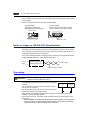
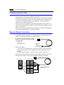
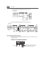
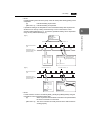
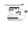
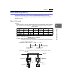
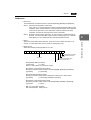
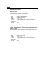
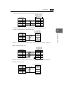
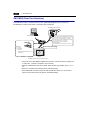
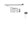
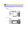
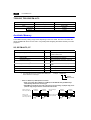
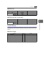
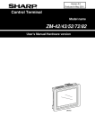
3. Wiring of the communication cable
Do not run the communication cable with high voltage circuits.
Communication cable
Communication cable
Power cable/control line
Wiring duct
Power cable/control line
Insulation lock
Do not run the communication line with high voltage lines in the same duct or bundle them
together using insulation locks. It may cause inferior condition for noise preventive means.
(5) Coin type lithium battery (See page. 1-23 through 1-25)
When using the calendar function or SRAM memory (for battery backup of sampling data or
other data), make sure to set the battery.
SRAM memory data or the contents of the calendar are not restored if the battery power is not
supplied.
A lithium battery has its expiration date. Expiration date is usually five years (at ambient
temperature of 25 C). If the battery is used at high temperatures, however, the battery power
may be lowered sooner. When using the battery for significant use such as setting data that is
hard to recover once lost, be sure to set the alarm of the lower battery power and replace the
battery when alarmed.
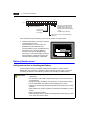
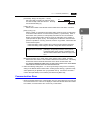
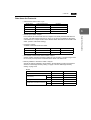
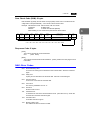
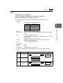
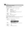
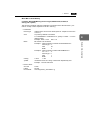
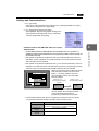
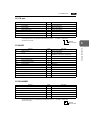
Detection of lower battery power
The internal system memory, $s167, of the ZM-300 series has a function that shows the battery
condition. It is strongly recommended to build an indication lamp of lower battery power in your
screen data.
[Settings]
To build an indication lamp in an abnormal screen made with ZM-71SE:
1. In the lamp parts settings, make an indication lamp whose character sequence reads "Lower
Battery Power."
2. Select "$s167-04" for the lamp memory.
3. Put it in the appropriate screen. When the battery power is lowered, the indication lamp turns
on.
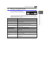
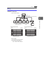
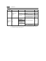
Battery condition in the internal memory, $s167 (one word data)
MSB
15
0
LSB
14 13
12
11
10
0
0
0
0
0
09 08
07
06
05
04
03 02
01
00
0
0
0
0
0
0
0
0
0
00 : normal power
01 : power lowered
02 : battery not inserted
0
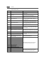
Contents
Safety Precautions
Handling Precautions
Chapter 1
Hardware Specifications
1.
Outline ............................................................................................................................. 1-1
2.
Model Name and Peripheral Equipment ......................................................................... 1-2
Model name of LCD Control Terminal ......................................................................................... 1-2
Peripheral Equipment .................................................................................................................. 1-3
3.
System Composition ....................................................................................................... 1-7
4.
Specifications .................................................................................................................. 1-8
General Specifications ................................................................................................................. 1-8
Display Specifications .................................................................................................................. 1-9
Touch Panel Specifications.......................................................................................................... 1-9
Function Switch Specifications .................................................................................................. 1-10
Interface Specifications.............................................................................................................. 1-10
Clock and Backup Memory Specifications................................................................................. 1-10
Drawing Environment................................................................................................................. 1-11
Display Function Specifications ................................................................................................. 1-11
Function Performance Specifications ........................................................................................ 1-12
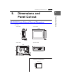
5.
Dimensions and Panel Cut-out...................................................................................... 1-13
ZM-350/360 series External View and Dimensions ................................................................... 1-13
ZM-370 series External View and Dimensions .......................................................................... 1-14
ZM-380 series External View and Dimensions .......................................................................... 1-15
6.
Names and Functions of Components .......................................................................... 1-16
7.
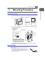
Mounting Procedure ...................................................................................................... 1-19
Mounting Procedure................................................................................................................... 1-19
Mounting Angle .......................................................................................................................... 1-19
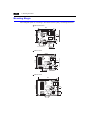
Mounting Margin ........................................................................................................................ 1-20
8.
Power Supply Cable Connection................................................................................... 1-21
Power Supply Cable Connection ............................................................................................... 1-21
Notes on Usage of 100-240 VAC Specifications ....................................................................... 1-22
Grounding .................................................................................................................................. 1-22
9.
Coin-type Lithium Battery .............................................................................................. 1-23
Battery Mounting Procedure ...................................................................................................... 1-23
Battery Replacement ................................................................................................................. 1-24
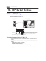
10. DIP Switch Setting......................................................................................................... 1-26
DIP Switch (DIPSW) Setting ...................................................................................................... 1-26
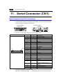
11. Serial Connector (CN1) ................................................................................................. 1-28
Serial Connector for PLC Connection........................................................................................ 1-28
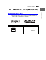
12. Modular Jack (MJ1/MJ2)................................................................................................1-29
Modular Jack 1 (MJ1)/2 (MJ2) ................................................................................................... 1-29
ZM-71SE Setting........................................................................................................................ 1-30
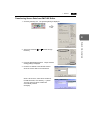
Transferring Screen Data........................................................................................................... 1-32
Barcode Reader Connection...................................................................................................... 1-32
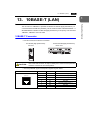
13. 10BASE-T (LAN)............................................................................................................1-33
10BASE-T Connector ................................................................................................................ 1-33
Notes on Wiring ......................................................................................................................... 1-34
14. CF Card (CF) .................................................................................................................1-35
Recommended CF Card ............................................................................................................ 1-35
Mounting and Dismounting the CF Card.................................................................................... 1-35
Notes on Handling the CF Card ................................................................................................. 1-36
15. Printer Connection (PRINTER) ......................................................................................1-37
Printer Connector (PRINTER).................................................................................................... 1-37
Connection with Printer through Serial Interface ....................................................................... 1-38
16. Terminal Converter (ZM-1TC)........................................................................................1-39
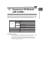
17. Expansion I/O Module (ZM-322ME) ..............................................................................1-41
18. Card Recorder (ZM-1REC) ............................................................................................1-46
19. Cable for transporting the panel (ZM-80C) ....................................................................1-47
20. 2 Port Adapter (ZM-1MD2) ............................................................................................1-48
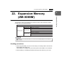
21. Expansion Memory (ZM-300EM) ...................................................................................1-52
22. Expansion Memory (ZM-300SM) ...................................................................................1-55
Chapter 2
1.
LCD Control Terminal Operations
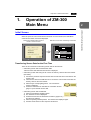
Operation of ZM-300 Main Menu .....................................................................................2-1
Initial Screen ................................................................................................................................ 2-1
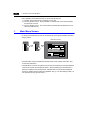
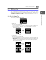
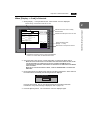
1.
Main Menu Screen .............................................................................................................. 2-2
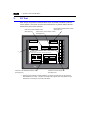
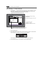
2.
I/O Test ............................................................................................................................... 2-4
2-1. Self-loop Test ...................................................................................................................... 2-5
2-2. Print Check.......................................................................................................................... 2-8
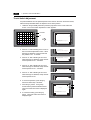
2-3. SYSTEM & Function Switch Test........................................................................................ 2-8
2-4. Touch Switch Test............................................................................................................... 2-9
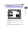
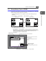
3.
Card Menu Screen ............................................................................................................ 2-11
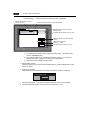
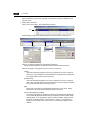
3-1. CREC Menu Screen.......................................................................................................... 2-12
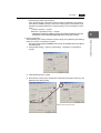
3-2. Transferring Screen Data from a CF Card ........................................................................ 2-15
3-3. Saving Backup Copies of SRAM....................................................................................... 2-21
3-4. Messages during Data Transfer........................................................................................ 2-23
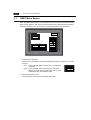
4.
Ethernet............................................................................................................................. 2-24
5.
SRAM/Clock...................................................................................................................... 2-27
6.
Extension Program Information......................................................................................... 2-28
7.
Extended Function Setting ................................................................................................ 2-29
2.
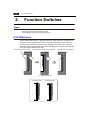
Function Switches ......................................................................................................... 2-30
Types ......................................................................................................................................... 2-30
[SYSTEM] Switch....................................................................................................................... 2-30
3.
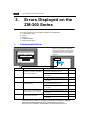
Errors Displayed on the ZM-300 Series ........................................................................ 2-32
Chapter 3
1.
1.
Communication Error ........................................................................................................ 2-32
2.
Check................................................................................................................................ 2-35
3.
Warning............................................................................................................................. 2-35
4.
SYSTEM ERROR ............................................................................................................. 2-36
5.
Touch Switch is Active ...................................................................................................... 2-36
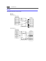
Serial Communications
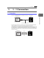
1 : 1 Connection .............................................................................................................. 3-1
1 : 1 Connection........................................................................................................................... 3-1
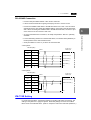
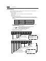
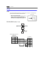
Wiring........................................................................................................................................... 3-2
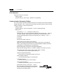
ZM-71SE Setting.......................................................................................................................... 3-3
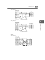
2.
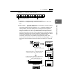
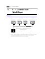
1 : n Connection (Multi-drop)........................................................................................... 3-9
1 : n Connection........................................................................................................................... 3-9
Wiring (RS-422/485) .................................................................................................................... 3-9
ZM-71SE Setting........................................................................................................................ 3-10
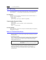
Notes on Communication Errors................................................................................................ 3-10
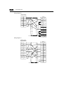
3.
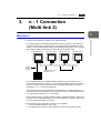
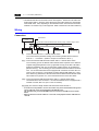
n : 1 Connection (Multi-link 2)........................................................................................ 3-11
Multi-link 2.................................................................................................................................. 3-11
Wiring......................................................................................................................................... 3-12
ZM-71SE Setting........................................................................................................................ 3-14
Communication Error ................................................................................................................. 3-15
4.
n : 1 Connection (Multi-link)........................................................................................... 3-16
Multi-link..................................................................................................................................... 3-16
Wiring......................................................................................................................................... 3-17
ZM-71SE Setting........................................................................................................................ 3-18
5.
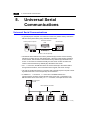
Universal Serial Communications ................................................................................. 3-20
Universal Serial Communications .............................................................................................. 3-20
6.
ZM-Link ......................................................................................................................... 3-21
ZM-Link ...................................................................................................................................... 3-21
Wiring......................................................................................................................................... 3-22
ZM-71SE Setting........................................................................................................................ 3-24
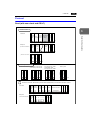
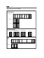
Protocol...................................................................................................................................... 3-25
NAK: Error Codes ...................................................................................................................... 3-29
1-byte Character Code List ........................................................................................................ 3-30
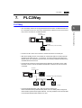
7.
PLC2Way.......................................................................................................................3-31
PLC2Way ................................................................................................................................... 3-31
Limitations on Connection at the MJ Port .................................................................................. 3-32
PLCs Compatible with PLC2Way Connection at MJ Port .......................................................... 3-32
Wiring......................................................................................................................................... 3-33
ZM-71SE Setting – System Setting ........................................................................................... 3-35
ZM-71SE Setting – When the temperature control network/PLC2Way table is used: ............... 3-38
Indirect Memory Designation ..................................................................................................... 3-45
User Log Read for YOKOGAWA’s PLC..................................................................................... 3-46
Processing Cycle ....................................................................................................................... 3-47
Notes on Screen Data Transfer ................................................................................................. 3-48
System Memory ......................................................................................................................... 3-49
Chapter 4
1.
Network Communications
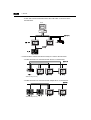
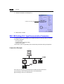
Ethernet ...........................................................................................................................4-1
Ethernet ....................................................................................................................................... 4-1
Notes on Ethernet Communications ............................................................................................ 4-3
IP Address for the ZM-300 Series................................................................................................ 4-3
Communication Network Module ZM-80NU/80NU2 .................................................................... 4-3
Wiring........................................................................................................................................... 4-5
Transferring Screen Data............................................................................................................. 4-8
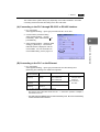
ZM-71SE Setting (PLC Type/Communication Parameter) ........................................................ 4-10
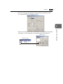
ZM-71SE Setting (Network Table Editing) ................................................................................. 4-14
ZM-71SE Setting (Macro) .......................................................................................................... 4-19
System Memory ......................................................................................................................... 4-22
Ethernet Access Functions (HKEtn10.DLL) ............................................................................... 4-26
Server Communication Procedure ............................................................................................. 4-44
Error Display .............................................................................................................................. 4-45
2.
FL-net.............................................................................................................................4-48
FL-net......................................................................................................................................... 4-48
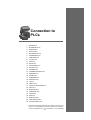
Chapter 5
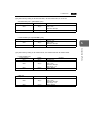
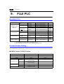
1.
Connection to PLCs
SHARP PLC.....................................................................................................................5-1
Available PLCs............................................................................................................................. 5-1
Communication Setting................................................................................................................ 5-1
JW Series: Link Unit Switch Setting ............................................................................................. 5-2
JW100/70H COM Port, JW20 COM Port: System Memory Setting ............................................. 5-2
Available Memory ........................................................................................................................ 5-4
Wiring........................................................................................................................................... 5-5
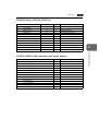
2.
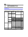
MITSUBISHI PLC............................................................................................................ 5-8
Available PLCs............................................................................................................................. 5-8
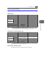
Communication Setting.............................................................................................................. 5-11
A Series Link, QnA Series Link: Switch Setting ......................................................................... 5-13
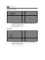
Available Memory ...................................................................................................................... 5-15
Wiring......................................................................................................................................... 5-18
A Link + Net10 ........................................................................................................................... 5-22
ZM-1MD2 (Dual Port Interface).................................................................................................. 5-24
Ladder Transfer Function........................................................................................................... 5-25
3.
OMRON PLC................................................................................................................. 5-29
Available PLCs........................................................................................................................... 5-29
Communication Setting.............................................................................................................. 5-31
Available Memory ...................................................................................................................... 5-32
Wiring......................................................................................................................................... 5-33
SYSMAC CS1 DNA ................................................................................................................... 5-36
4.
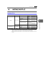
HITACHI PLC ................................................................................................................ 5-37
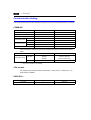
Available PLCs........................................................................................................................... 5-37
Communication Setting.............................................................................................................. 5-38
HIDIC-H: Switch Setting............................................................................................................. 5-39
Available Memory ...................................................................................................................... 5-39
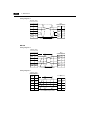
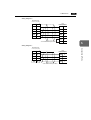
Wiring......................................................................................................................................... 5-41
5.
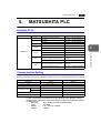
MATSUSHITA PLC ....................................................................................................... 5-43
Available PLCs........................................................................................................................... 5-43
Communication Setting.............................................................................................................. 5-43
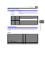
MEWNET: Link Unit Switch Setting ........................................................................................... 5-44
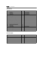
Available Memory ...................................................................................................................... 5-44
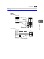
Wiring......................................................................................................................................... 5-45
6.
YOKOGAWA PLC ......................................................................................................... 5-47
Available PLCs........................................................................................................................... 5-47
Communication Setting.............................................................................................................. 5-48
Available Memory ...................................................................................................................... 5-49
Wiring......................................................................................................................................... 5-50
7.
YASKAWA PLC............................................................................................................. 5-52
Available PLCs........................................................................................................................... 5-52
Communication Setting.............................................................................................................. 5-52
Available Memory ...................................................................................................................... 5-53
Wiring......................................................................................................................................... 5-54
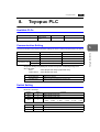
8.
Toyopuc PLC................................................................................................................. 5-57
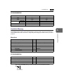
Available PLCs........................................................................................................................... 5-57
Communication Setting.............................................................................................................. 5-57
Switch Setting ............................................................................................................................ 5-57
Available Memory ...................................................................................................................... 5-58
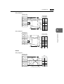
Screen Editing (Memory Input) .................................................................................................. 5-58
Wiring......................................................................................................................................... 5-59
9.
FUJI PLC .......................................................................................................................5-60
Available PLCs........................................................................................................................... 5-60
Communication Setting.............................................................................................................. 5-60
MICREX-F Series, FLEX-PC Series: Switch Setting ................................................................. 5-61
Available Memory ...................................................................................................................... 5-62
Wiring......................................................................................................................................... 5-64
10. KOYO PLC.....................................................................................................................5-66
Available PLCs........................................................................................................................... 5-66
Communication Setting.............................................................................................................. 5-67
Available Memory ...................................................................................................................... 5-68
Switch Setting ............................................................................................................................ 5-69
Wiring......................................................................................................................................... 5-71
11. Allen-Bradley PLC..........................................................................................................5-74
Available PLCs........................................................................................................................... 5-74
Communication Setting.............................................................................................................. 5-75
Available Memory ...................................................................................................................... 5-76
PLC-5 Series: Switch Setting ..................................................................................................... 5-78
SLC500 Series, Micro Logix 100: Transmission Parameter Setting .......................................... 5-80
Wiring......................................................................................................................................... 5-81
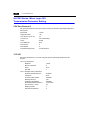
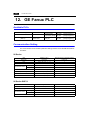
12. GE Fanuc PLC...............................................................................................................5-84
Available PLCs........................................................................................................................... 5-84
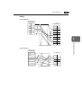
Communication Setting.............................................................................................................. 5-84
Available Memory ...................................................................................................................... 5-85
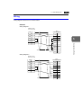
Wiring......................................................................................................................................... 5-86
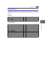
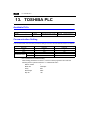
13. TOSHIBA PLC ...............................................................................................................5-88
Available PLCs........................................................................................................................... 5-88
Communication Setting.............................................................................................................. 5-88
Available Memory ...................................................................................................................... 5-89
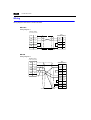
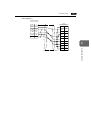
Wiring......................................................................................................................................... 5-89
14. TOSHIBA MACHINE PLC..............................................................................................5-90
Available PLCs........................................................................................................................... 5-90
Communication Setting.............................................................................................................. 5-90
Available Memory ...................................................................................................................... 5-90
Wiring......................................................................................................................................... 5-91
15. SIEMENS PLC...............................................................................................................5-92
Available PLCs........................................................................................................................... 5-92
Communication Setting.............................................................................................................. 5-92
Available Memory ...................................................................................................................... 5-94
Wiring......................................................................................................................................... 5-97
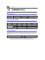
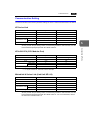
16. SHINKO PLC ...............................................................................................................5-100
Available PLCs......................................................................................................................... 5-100
Communication Setting............................................................................................................ 5-100
Available Memory .................................................................................................................... 5-100
Wiring....................................................................................................................................... 5-101
17. SAMSUNG PLC .......................................................................................................... 5-102
Available PLCs......................................................................................................................... 5-102
Communication Setting............................................................................................................ 5-102
Available Memory .................................................................................................................... 5-102
Wiring....................................................................................................................................... 5-103
18. KEYENCE PLC ........................................................................................................... 5-104
Available PLCs......................................................................................................................... 5-104
Communication Setting............................................................................................................ 5-105
Available Memory .................................................................................................................... 5-106
Wiring....................................................................................................................................... 5-108
19. LG PLC........................................................................................................................ 5-110
Available PLCs......................................................................................................................... 5-110
Communication Setting............................................................................................................ 5-110
Available Memory .................................................................................................................... 5-111
Wiring....................................................................................................................................... 5-113
20. FANUC PLC ................................................................................................................ 5-115
Available PLCs......................................................................................................................... 5-115
Communication Setting............................................................................................................ 5-115
Available Memory .................................................................................................................... 5-115
Wiring....................................................................................................................................... 5-116
21. FATEK AUTOMATION PLC........................................................................................ 5-118
Available PLCs......................................................................................................................... 5-118
Communication Setting............................................................................................................ 5-118
Available Memory .................................................................................................................... 5-118
Wiring....................................................................................................................................... 5-119
22. IDEC PLC.................................................................................................................... 5-120
Available PLCs......................................................................................................................... 5-120
Communication Setting............................................................................................................ 5-120
Available Memory .................................................................................................................... 5-120
Wiring....................................................................................................................................... 5-121
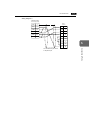
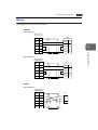
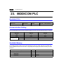
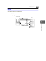
23. MODICON PLC ........................................................................................................... 5-122
Available PLCs......................................................................................................................... 5-122
Communication Setting............................................................................................................ 5-122
Available Memory .................................................................................................................... 5-122
Wiring....................................................................................................................................... 5-123
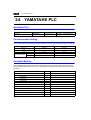
24. YAMATAKE PLC......................................................................................................... 5-124
Available PLCs......................................................................................................................... 5-124
Communication Setting............................................................................................................ 5-124
Available Memory .................................................................................................................... 5-124
Wiring....................................................................................................................................... 5-125
25. TAIAN PLC.................................................................................................................. 5-126
Available PLCs......................................................................................................................... 5-126
Communication Setting............................................................................................................ 5-126
Available Memory .................................................................................................................... 5-126
Wiring....................................................................................................................................... 5-127
26. SAIA PLC.....................................................................................................................5-128
Available PLCs......................................................................................................................... 5-128
Communication Setting............................................................................................................ 5-128
S-BUS Configuration................................................................................................................ 5-128
Available Memory .................................................................................................................... 5-128
Wiring....................................................................................................................................... 5-129
27. MOELLER PLC............................................................................................................5-130
Available PLCs......................................................................................................................... 5-130
Communication Setting............................................................................................................ 5-130
Available Memory .................................................................................................................... 5-130
Wiring....................................................................................................................................... 5-131
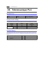
28. Telemecanique PLC ....................................................................................................5-132
Available PLCs......................................................................................................................... 5-132
Communication Setting............................................................................................................ 5-132
Available Memory .................................................................................................................... 5-132
Wiring....................................................................................................................................... 5-133
29. Automationdirect PLC ..................................................................................................5-134
Available PLCs......................................................................................................................... 5-134
Communication Setting............................................................................................................ 5-134
Available Memory .................................................................................................................... 5-135
Wiring....................................................................................................................................... 5-135
Hardware
Specifications
1.
Outline
2.
Model Name and Peripheral Equipment
3.
System Composition
4.
Specifications
5.
Dimensions and Panel Cut-out
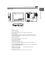
6.
Names and Functions of Components
7.
Mounting Procedure
8.
Power Supply Cable Connection
9.
Coin-type Lithium Battery
10. DIP Switch Setting
11. Serial Connector (CN1)
12. Modular Jack (MJ1/MJ2)
13. 10BASE-T (LAN)
14. CF Card (CF)
15. Printer Connection (PRINTER)
16. Terminal Converter (ZM-1TC)
17. Expansion I/O Module (ZM-322ME)
18. Card Recorder (ZM-1REC)
19. Cable for Screen Transfer (ZM-80C)
20. 2 Port Adapter (ZM-1MD2)
21. Expansion Memory (ZM-300EM)
22. Expansion Memory (ZM-300SM)
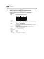
1. Outline
1.
1-1
Outline
Note
To make screen data for the ZM-300 series, use ZM-71SE, Ver.2.0.0.0 or
higher.(When using ZM-373TA/371TL/373TL, ZM-383S/383SA, use version
2.1.0.0 or a newer version.)
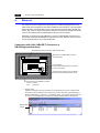
The ZM-300 series inherits and heightens the features of the ZM-42 to 82 series as
described below.
1. 32K-color Display
32,768-color display makes colorful expression possible. Bitmap files are clearly
displayed in brilliant colors.
2. CF Card Interface as Standard
The CF card can be used for saving multiple screen data, sampling data, recipe data,
hard copy images, and other various usages. Large-sized video capture images, JPEG
or WAV files can be saved.
3. Connector for 10BASE-T (for high-performance type only)
This connector enables Ethernet connection with a host computer. High-speed
communications are possible via Ethernet for uploading/downloading screen data and
reading/writing data from/to the server.
4. Video Display Upgraded (for high-performance type only, optional)
The video display function is upgraded drastically to allow: saving the current video
screen, taking snapshots of multiple exposures, superimposing a semi-transparent
operation screen on a video display, showing four video channels at the same time, and
so on.
5. Web Server Function (for high-performance type only)
The ZM-300 (high-performance) screens are converted into HTML files and displayed
on the WWW browser using the Ethernet.
6. Animation Function
The animation function enables representation of the field close to the real image.
7. Play of WAV File (for high-performance type only, optional)
WAV files can be played with ease simply by connecting the option unit to the speaker.
It is possible to use sound for notifying the field conditions, such as an occurrence of an
error. The monitoring operator can work from a distance.
8. Matrix touch panel
As for ZM-373TA/373TL or ZM-383S/383SA, 2-point touch is possible on the screen,
allowing the models to have a broader range of applications.
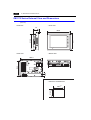
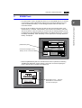
Hardware Specifications
The LCD Control Terminal ZM-300 series is programmable display equipment with the LCD
screen and the touch panel functions.
The ZM-300 series programlessly communicates to a programmable controller (PLC),
displays a screen in various ways based on the screen data, and allows you to input data
through the touch panel.
1
1-2
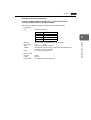
2.
2. Model Name and Peripheral Equipment
Model Name and
Peripheral Equipment
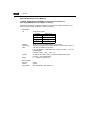
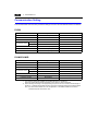
Model name of LCD Control Terminal
* Compliant with UL/CSA, CE
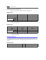
Specifications
Series Model name
ZM-350
Series ZM-352D 7.7 type STN color, 640 480 dots, standard, DC power supply, Analogue touch panel*
ZM-360 ZM-362S 8.4 type TFT color, 800 600 dots, standard, DC power supply, Analogue touch panel*
Series ZM-362SA 8.4 type TFT color, 800 600 dots, high-performance, DC power supply, Analogue touch panel*
ZM-371T
10.4 type TFT color, 640 480 dots, standard, AC power supply, Analogue touch panel
ZM-371TA 10.4 type TFT color, 640 480 dots, high-performance, AC power supply, Analogue touch panel
ZM-372T
10.4 type TFT color, 640 480 dots, standard, DC power supply, Analogue touch panel*
ZM-372TA 10.4 type TFT color, 640 480 dots, high-performance, DC power supply, Analogue touch panel*
ZM-373TA 10.4 type TFT color, 640 480 dots, high-performance, AC power supply, Matrix touch panel
ZM-370
ZM-371TL 10.4 type TFT color (128 colors), 640 480 dots, standard, AC power supply, Analogue touch panel
Series
ZM-373TL 10.4 type TFT color (128 colors), 640 480 dots, standard, AC power supply, Matrix touch panel
ZM-371S
10.4 type TFT color, 800 600 dots, standard, AC power supply, Analogue touch panel
ZM-371SA 10.4 type TFT color, 800 600 dots, high-performance, AC power supply, Analogue touch panel
ZM-372S
10.4 type TFT color, 800 600 dots, standard, DC power supply, Analogue touch panel*
ZM-372SA 10.4 type TFT color, 800 600 dots, high-performance, DC power supply, Analogue touch panel*
ZM-381S
12.1 type TFT color, 800 600 dots, standard, AC power supply, Analogue touch panel
ZM-381SA 12.1 type TFT color, 800 600 dots, high-performance, AC power supply, Analogue touch panel
ZM-380 ZM-382S 12.1 type TFT color, 800 600 dots, standard, DC power supply, Analogue touch panel*
Series ZM-382SA 12.1 type TFT color, 800 600 dots, high-performance, DC power supply, Analogue touch panel*
ZM-383S
12.1 type TFT color, 800 600 dots, standard, AC power supply, Matrix touch panel
ZM-383SA 12.1 type TFT color, 800 600 dots, high-performance, AC power supply, Matrix touch panel
2. Model Name and Peripheral Equipment
1-3
1
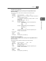
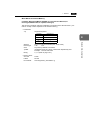
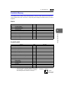
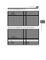
Peripheral Equipment
The following options are available for using the ZM-300 series more effectively
Model name
Use
ZM-301EU Video input sound output module
Option module
ZM-302EU RGB input sound output module
ZM-303EU RGB output sound output module
ZM-304EU Sound output module
ZM-80NU
Network module
ZM-80NU2
The module to connect ZM-300 to Ethernet. It supports UDP/IP,
corresponds to FA link protocol through FL-net and supports
cyclic transmission and message transmission (word read/write).
- ZM-80NU for Ethernet/FL-net (Ver.1.00)
- ZM-80NU2 for Ethernet/FL-net (Ver.2.00)
Note: You cannot use ZM-80NU and ZM-80NU2 on the same line.
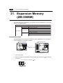
ZM-300EM
A flash memory used to expand the memory capacity for screen
data. Its capacity is 8MB
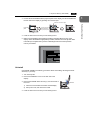
ZM-300SM
An SRAM memory used to backup sampling data, internal
memory, and memo pad. Its capacity is 512KB.
Expansion memory
Used to connect to a PLC at the RS-422/485 terminal block.
ZM-1TC
Expansion I/O module ZM-322ME Used as an external I/O module for PLC. Provides 16 input pins and 16 output pins.
Used for screen data backup or for recording of the memory
ZM-1REC
Card recorder
manager function and the data logging function.
The module to convert the connector for a programmer of
ZM-1MD2
2 ports adapter
MITSUBISHI’s ACPU/QnACPU/FXCPU into a two-port connector.
Used to connect ZM-300 to a personal computer or connect a
Screen data transfer
ZM-80C
personal computer to ZM-1REC.
cable
ZM-300PC Used to connect ZM-300 to a printer.
Printer cable
Terminal converter
Barcode reader
connection cable
ZM-80BC
Multi-link 2
master cable
ZM-80MC
MJ-to-D-sub
conversion cable
Installation adapter
Screen edit software
Used to connect ZM-300 to a bar code reader.
Used to connect ZM-300 master station to the ZM-300 slave
station in the Multi-link 2 connection.
Used to converts a Dsub 25-pin connector (millimeter screw type)
ZM-300CC
into a modular jack.
Used to attach ZM-370 to the panel cut of a preceding model
ZM-300PD
(ZM-70T/70D).
Used to make screen data (compliant with
ZM-71S
Japanese version Windows95/98/NT4.0/Me/2000/XP).
ZM-300 needs Ver.2.0.0.0 or higher version.
ZM-71SE English version (When using ZM-373TA/371TL/373TL, ZM383S/383SA, use version 2.1.0.0 or a newer version.)
ZM-71SE (screen edit software: English version)
Application software for editing display data for the ZM series.
(Windows95/98/NT4.0/Me/2000/XP compatible) The ZM-300 series is
supported with ver. 2.00 and later.
Hardware Specifications
Product name
1-4
2. Model Name and Peripheral Equipment
ZM-30*EU (option module)
This option module can only be mounted on the ZM-300
(high-performance) model.
ZM-301EU → Video input + sound output module
Video images can be displayed on ZM-300 (high-performance)
directly. WAV files can be played at an external speaker.
ZM-302EU→ RGB input + sound output module
Screen images displayed on a CRT display can be shown on
ZM-300 (high-performance). WAV files can be played at an
external speaker.
ZM-303EU → RGB output + sound output module
Screen images displayed on ZM-300 (high-performance) can be
shown on a CRT display. WAV files can be played at an external
speaker.
ZM-304EU → Sound output module
WAV files can be played at an external speaker.
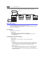
ZM-300EM (FLASH memory cassette)
Extension print circuit board to extend the memory for screen data.
The capacity of FLASH memory is 8 Mbyte.
ZM-300EM (SRAM cassette)
Extension print circuit board to back-up the memory for sampling data,
ZM-300 internal memory and memo pad. The capacity of an SRAM
cassette is 512 Kbyte.
1
CN
SW
1
TB
1
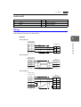
ZM-1TC (terminal converter)
Used for connection between the ZM-300 series and a PLC at the
RS-422/485 terminal block.
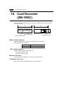
ZM-1REC (card recorder)
The card recorder creates a backup copy of screen data or works as an
external memory storage system for memory manager and data
logging functions.
2. Model Name and Peripheral Equipment
1-5
ZM-CARD SOFT (memory card editor)
Application software for editing data stored on a memory card.
(Windows95/98/NT4.0/Me/2000/XP compatible)
G
P
P
ZM-1
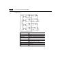
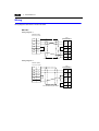
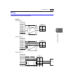
ZM-1MD2 (ACPU/QnACPU/FXCPU dual port interface)
Add-on connector with two ports, specifically designed for the
connector on the MITSUBISHI’s ACPU/QnACPU/FXCPU programmer.
Operability can be improved when directly connecting the ZM-300
series to the ACPU/QnACPU/FXCPU programmer.
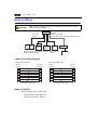
MD2
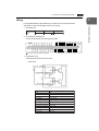
123
GD
DC24V
IN1
FG
IN0
IN2
IN3
IN4
IN5
IN6
IN7
IN8
MJ1
IN9
IN10
IN11
IN12
IN13
IN14
IN15
OUT1
COM+
OUT0
OUT2
OUT3
OUT4
OUT5
OUT6
OUT7
COM1
OUT8
OUT9
OUT10
OUT11
OUT12
OUT13
OUT14
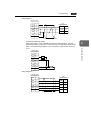
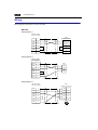
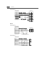
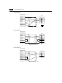
ZM-322ME (expansion I/O module)
Used as an external I/O module for PLC. It has 16 inputs and 16
outputs.
COM2
OUT15
ZM-80NU, ZM-80NU2 (network module)
Used for communications with Ethernet and FL-net network.
• ZM-80NU : Ethernet/FL-net (Ver.1.00)
• ZM-80NU2 : Ethernet/FL-net (Ver.2.00)
This unit enables connection of multiple ZM-300 series to a single PLC.
Since other devices on the same network can be connected, it brings
about the reduction in costs of the whole system. About the
ZM-80NU/80NU2 in detail, see the “ZM-80NU/80NU2 User’s Manual”
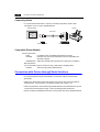
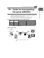
ZM-80C (screen data transfer cable) 3 m
Used for connection between the ZM-300 series and a personal
computer, or a personal computer and the card recorder (ZM-1REC).
ZM-300PC (printer cable) 2.5 m
Used for connection between the ZM-300 series and a printer.
1
Hardware Specifications
会
式
株
機
電
紘
発
F
56
C2
RE 社
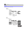
Memory Card on the market compliant with JEIDA ver. 4.0
Used with the card recorder when having a backup copy of screen data
or saving data on an external medium for memory manager and data
logging functions.
SRAM
256 k, 512 k, 1 M, 2 M, 4 Mbyte
1-6
2. Model Name and Peripheral Equipment
ZM-80BC (barcode reader connection cable) 3 m
Used for connection between the ZM-300 series and a barcode reader.
ZM-80MC (multi-link 2 master cable) 3 m
Used for Multi-Link 2 connection between the ZM-300 master station
and the ZM-300 slave station.
ZM-300CC (MJ-to-D-sub conversion cable) 0.3 m
Used for connection between the ZM-300 series and a PLC via
PLC2Way.
ZM-361GS/371GS/381GS (protective sheet)
This sheet protects the operation panel surface. (5 sheets/set)
• ZM-361GS : For ZM-350/360 Series
• ZM-371GS : For ZM-370 Series
• ZM-381GS : For ZM-380 Series
ZM-362GS/372GS/382GS (protective sheet)
This anti-glare sheet protects the operation panel surface.
(5 sheets/set)
• ZM-362GS : For ZM-350/360 Series
• ZM-372GS : For ZM-370 Series
• ZM-382GS : For ZM-380 Series
ZM-300BT (battery for replacement)
Replacement lithium battery for the ZM-300 series.
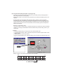
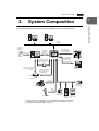
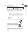
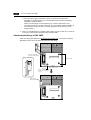
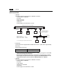
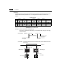
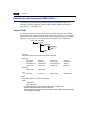
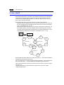
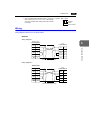
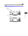
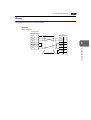
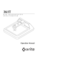
3. System Composition
3.
1-7
1
System Composition
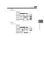
Hardware Specifications
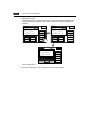
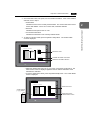
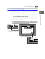
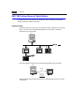
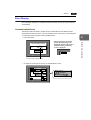
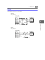
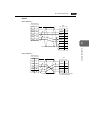
The following illustration shows possible system configurations using the ZM-300 series.
disc
disc
RESET
RESET
Personal computer (PC)
Personal computer (PC)
Ethernet
Screen edit
software for
ZM series
*1
Transferring
screen data
ZM-80C
disc
Creating screens
SYSTEM
F1
During operation
(Link communication)
RS-232C/RS-422
F2
F3
F4
F5
F6
RESET
F7
ZM-71SE
POWER
ZM-300
Personal computer (PC)
*2
Transferring screen data
Transferring recipe data
Saving sampling data
etc.
During operation
(Universal serial
communication)
Link module
RS-232C/RS-422
CompactFlash
Card
CF card
Transferring screen data
Transferring other data
General-purpose
computer
Transferring screen data
Memory manager
Data logging function
ZM-1REC cable
ZM-80C
Card recorder
ZM-1REC
Printer cable
ZM-300PC
Speaker
(Sound output)
Printer
Cable
ZM-80BC
Video camera
(Video input)
Barcode reader
Personal
Display
computer
(RGB output)
(RGB input)
*1 High-performance models (ZM-3***A) are equipped with the Ethernet connector.
*2 The option module (ZM-30*EU) is required.
1-8
4. Specifications
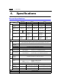
4.
Specifications
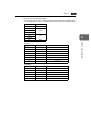
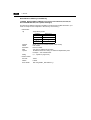
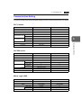
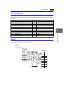
General Specifications
Model
Item
Power Supply
Rated Voltage
ZM-350/360
ZM-370
AC power supply
DC power supply
AC power supply
DC power supply
24 VDC
100 - 240 VAC
24 VDC
100 - 240 VAC
24 VDC
Permissible Range
of Voltage
24 VDC ±10%
100 - 240 VAC
±10%
24 VDC ±10%
100 - 240 VAC
±10%
24 VDC ±10%
Permissible
Momentary Power
Failure
Within 1 ms
Within 20 ms
Within 1 ms
Within 20 ms
Within 1 ms
60 VA or less
30 W or less
60 VA or less
30 W or less
Power Consumption
(Maximum Rating)
Rush Current
Withstand Voltage
ZM-350
15 W or
less
ZM-360
22 W or
less
25 A, 0.7 ms
DC external
terminals to FG:
500 VAC,
1 minute
For 100 VAC:
16 A, 6 ms
For 200 VAC:
32 A, 7 ms
Physical Environment
Mechanical
Working
Conditions
Electrical
Working
Conditions
Ambient
Temperature
30A, 1 ms
AC external
terminals to FG:
1500 VAC,
1 minute
Insulation Resistance
DC external
terminals to FG:
500 VAC,
1 minute
For 100 VAC:
16 A, 6 ms
For 200 VAC:
32A, 7 ms
AC external
terminals to FG:
1500 VAC,
1 minute
30 A, 1 ms
DC external
terminals to FG:
500 VAC,
1 minute
500 VDC, 10 MΩ or above
0°C to +50°C
When the mounting angle is between 15° and 45° or when you use the option module, ZM-301EU
(video input and audio output), adjust the ambient temperature between 0°C and +40°C.
Storage Ambient
Temperature
−10°C to +60°C
Ambient Humidity
85%RH or less (without dew condensation)
Solvent Resistance
No cutting oil or organic solvent attached to the unit
Atmosphere
No corrosive gas or conductive dust
Vibration Resistance
Vibration frequency:
Single amplitude:
10 to 150 Hz, Acceleration: 9.8 m/s2 (1.0G)
0.075 mm, X, Y, Z: 3 directions for one hour
Shock Resistance
Pulse shape:
Peak acceleration:
Sine half wave
147 m/s2 (15G), X, Y, Z: 3 directions six times each
1500Vp-p (pulse width 1 μs, rising time: 1 ns)
Noise Resistance
Static Electricity
Discharge
Resistance
Compliant with IEC1000-4-2, contact: 6 kV, air: 8 kV
Grounding resistance: less than 100 Ω
Grounding
Protection structure:
Mounting Conditions
ZM-380
DC power supply
Structure
Form:
Mounting procedure:
Cooling System
front panel compliant with IP65 (when using gasket)
rear case: compliant with IP20
in a body
inserted in a mounting panel
Cooling naturally
Weight (kg)
Unit: approx. 1.5
Unit: approx. 2.4
(As for ZM-373TA/TL, about 2.8kg)
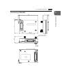
Dimensions
W × H × D (mm)
233 × 178 × 66.1
303.8 × 231.0 × 72.0
Panel Cut-out (mm)
+0.5
220.5 +0.5
−0 × 165.5 −0
289.0 +0.5 × 216.2 +0.5
−0
Case Color
Black (Munsell N2.0)
Material
PC/PS resin (Tarflon)
Accessories
Unit: approx. 2.7
(As for ZM-383S/SA, about 3.2kg)
326.4 × 259.6 × 72.0
+0.5
313.0 +0.5
−0 × 246.2 −0
Four mounting brackets, one instruction manual
4. Specifications
1-9
1
Display Specifications
ZM-352D
ZM-362S/SA
ZM-37*TL
STN
color LCD
Display Device
Effective Display
Area
ZM-37*T/TA
8.4-inch
Colors
128 colors
+16-color
blinks
32,768 colors
+16-color
blinks
Resolution
W × H (dots)
640 × 480
800 × 600
640 × 480
Dot Pitch
W × H (mm)
0.246 ×
0.246
0.213 × 0.213
0.33 × 0.33
200
350
220
25 : 1
250 : 1
+40, −30
±50
Contrast Ratio
Angle of Vertical
Visibility (°)
Angle of Horizontal
Visibility (°)
ZM-38*S/SA
TFT color LCD
7.7-inch
Brightness (cd/m2)
ZM-37*S/SA
10.4-inch
128 colors
+16-color
blinks
12.1-inch
32,768 colors
+16-color blinks
800 × 600
0.264 × 0.264
0.3075 ×
0.3075
350
280
350
350 : 1
300 : 1
300 : 1
350 : 1
+35, −55
+30, −20
+45, −55
+35, −45
+40, −45
±50
±45
±70
±50
±55
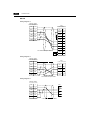
Backlight
Cold cathode rectifier (exchangeable by users)
Backlight Average
Life *1
Approx.
40,000 h
Approx. 50,000 h
Backlight
Auto OFF Function
Always ON, random setting
Contrast Adjustment
Brightness
Adjustment
Provided *2
Not provided
3 levels *2
Not provided
Surface Sheet
Material: Polycarbonate, 0.3 mm thick
POWER Lamp
ON when the power is supplied
*1 When the normal temperature is 25°C, and the surface luminance of the display is 50% of the
initial setting.
*2 Adjustable with function switches
Touch Panel Specifications
Analogue type
Item
Method
Switch Resolution
Mechanical Life
Surface
Treatment
Specifications
Analog resistance film type
1024 (W) x 1024 (H)
One million activations or more
Hard-coated, anti-glare
treatment 5%
Matrix type
Item
Specifications
Matrix resistance sensitive system
ZM-373TA/TL : 40 (W) x 24 (H)
Switches
ZM-383S/SA : 50 (W) x 30 (H)
Mechanical Life One million activations or more
Surface
Hard-coated, anti-glare
Treatment
treatment 5%
Method
Hardware Specifications
Model
Item
1-10
4. Specifications
Function Switch Specifications
Item
Specifications
Number of Switches
8
Method
Pressure sensitive
Mechanical Life
One million activations or more
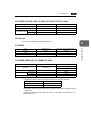
Interface Specifications
Item
Serial Interface for PLC
Connection
(D-sub 25-pin, female)
Serial Interface 1, 2 for Screen
Data Transfer/External
Connection
(Modular jack, 8-pin)
Specifications
RS-232C, RS-422/485
Asynchronous type
Data length:
7, 8 bits
Parity:
even, odd, none
Stop bit:
1, 2 bits
Baud rate:
4800, 9600, 19200, 38400, 57600, 76800, 115 kbps
RS-232C, RS-422/485 (2-wire connection)
ZM-1REC, Barcode, ZM-322ME, Multi-link 2,
PLC2Way, ZM-link, etc.
Printer Interface for Printer
Connection
Compliant with Centronics, half-pitch 36-pin
NEC:
PR201
EPSON:
ESC/P-J84, ESC/P super function, ESC/P24-J84
CBM292/293 printer *1, HP PCL Level 3
Barcode printer MR400
CF Card Interface
Compliant with CompactFlashTM
10BASE-T for Ethernet
Connection
(Standard with ZM-300 high
performance)
Compliant with IEEE802.3
Baud rate: 10 Mbps
Cables:
100 Ω unshielded twist-pair,
Category 5, maximum length = 100 m
*1 The CBM292/293 printer cannot print screen hard copies.
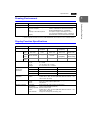
Clock and Backup Memory Specifications
Item
Battery Specification
Specifications
Coin-type lithium primary cell
Backup Memory
SRAM 64 Kbyte
Backup Time Period
5 years (ambient temperature at 25°C)
Battery Voltage Drop Detection
Provided (internal memory allocated)
Calendar Accuracy
Monthly deviation ±90 sec (ambient temperature at 25°C)
4. Specifications
1-11
1
Drawing Environment
Specifications
Drawing Method
Exclusive drawing software
Drawing Tool
Name of exclusive drawing software:
Personal computer:
OS:
Capacity of hard disk required:
Display:
ZM-71SE (Ver. 2.00 and later) *
Pentium II 450 MHz or above recommended
Windows95/98/Me/NT Ver. 4.0/2000/XP
Free space of approx. 460 Mbyte or more
(For minimum installation: approx. 105 Mbyte)
Resolution 800 × 600 or above recommended
* When using ZM-373TA/371TL/373TL, ZM-383S/383SA, use version 2.1.0.0 or a newer version.
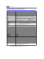
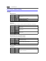
Display Function Specifications
Item
Specifications
Display Language*
Characters
Japanese
English/
European
Chinese
Chinese
(Simplified)
Korean
ANK code
Latin 1
ASCII code
ASCII code
ASCII code
2-byte
16-dot
JIS #1, #2 level
−−−−
Chinese
Chinese
(simplified)
Hangul
(without Kanji)
2-byte
32-dot
JIS #1 level
−−−−
−−−−
−−−−
−−−−
1/4-size
1-byte
Character Size
Number of
Displayable
Characters
1/4-size:
1-byte:
2-byte:
Enlarge:
8 × 8 dots
8 × 16 dots
16 × 16 dots or 32 × 32 dots
W: 1 to 8 times, H: 1 to 8 times
Resolution
640 × 480
800 × 600
1/4-size
80 columns × 60 lines
100 columns × 75 lines
1-byte
80 columns × 30 lines
100 columns × 37 lines
2-byte
40 columns × 30 lines
50 columns × 37 lines
Characters
Properties
Display properties: Normal, reverse, blink, bold, shadow
Colors:
32,768 colors + blink 16 colors (ZM-352D, ZM-371TL/373TL : 128
colors + blink 16 colors)
Graphics
Lines:
Circles:
Others:
Line, continuous line, box, parallelogram, polygon
Circle, arc, sector, ellipse, elliptical arc
Tile patterns
Graphic Properties
Line types:
Tile patterns:
Display properties:
Colors:
6 (thin, thick, dot, chain, broken, two-dot chain)
16 (incl. user-definable 8 patterns)
Normal, reverse, blink
32,768 colors + blink 16 colors (ZM-352D, ZM-371TL/373TL : 128
colors + blink 16 colors)
Foreground, background, boundary (line)
Color selection:
Hardware Specifications
Item
1-12
4. Specifications
Function Performance Specifications
Item
Specifications
Screens
Max. 1024
Screen Memory
Flash memory: Appox. 4,992 Kbyte (varies depending on the font)
Switches
768 per screen
Switch Actions
Set, reset, momentary, alternate, to light
(Possible to press a function switch and a display switch at the same time)
Lamps
Reverse, blink, exchange of graphics
768 per screen
Graphs
Pie, bar, panel meter and closed area graph:
Data Setting
Statistics and trend graphs:
Numerical Data Display
No limitation within 256 Kbyte per screen *1
Character Display
No limitation within 256 Kbyte per screen *1
Message Display
Resolution:
Sampling
No limitation within 256 Kbyte
per screen *1
Max. 256 per layer *2
640 × 480, max. 80 characters (1-byte)
800 × 600, max. 100 characters (1-byte)
No limitation within 256 Kbyte per screen *1
Sampling display of buffer data
(Constant sample, bit synchronize, bit sample, relay sample, alarm function)
Graphic Library
Max. 1024
Multi-Overlaps
Max. 1024
Data Blocks
Max. 2560
Messages
Max. 6144 lines
Patterns
Max. 1024
Macro Blocks
Max. 1024
Page Blocks
Max. 1024
Direct Blocks
Max. 1024
Screen Blocks
Max. 1024
Data Sheets
Max. 1024
Screen Library
Max. 1024
Animation (Frames)
Max. 1023
PLC2Way Table
Max. 32
Time Display
Time display function: provided
Hard Copy
Screen hard copy function: provided
Buzzer
Buzzer: provided, 2 sounds (short beep, long beep)
Auto OFF Function
Always ON, random setting
Self-diagnostic Function
Switch self-test function
Communication parameter setting check function
Communication check function
*1 The number of setting memory locations is limited to 1024 per screen.
*2 Layer: 4 per screen (base + 3 overlaps)
5. Dimensions and Panel Cut-out
5.
1
Hardware Specifications
Dimensions and
Panel Cut-out
ZM-350/360 Series External View and Dimensions
(Unit: mm)
• Side View
• Front View
66.1
233
SYSTEM
F1
F3
F4
F5
F6
POWER
F7
6.6
• Bottom View
220
LAN
CN6
Battery replacement.
CN5
MEMORY
220
CF
MJ2
CN1
• Panel Cut-out Dimensions
220.5 +0.5
-0
+0.5
PRINTER
MJ1
165.5 -0
24VDC
- +
24.3
165
See operating or maintenance
instruction for type of battery
to be used.
178
165
F2
• Rear View
1-13
1-14
5. Dimensions and Panel Cut-out
ZM-370 Series External View and Dimensions
(Unit: mm)
• Side View
• Front View
72
303.8
8
SYSTEM
F1
F3
F4
F5
F6
F7
POWER
• Rear View
• Bottom View
288.0
CN6
CN5
215.2
MEMORY
288.0
See operating or maintenance
instruction for type of battery
to be used.
CF
Battery replacement.
CN1
MJ1
MJ2
PRINTER
• Panel Cut-out Dimensions
289 +0.5
-0
216.2 +0.5
-0
LAN
35.2
100-240VAC
L
N
231
215.2
F2
5. Dimensions and Panel Cut-out
1-15
1
ZM-380 Series External View and Dimensions
(Unit: mm)
• Front View
72
326.4
259.6
245.2
8
F1
F2
F3
F4
SYSTEM
POWER
• Rear View
• Bottom View
312
CN6
CN5
MEMORY
312
CF
Battery replacement.
MJ1
MJ2
PRINTER
• Panel Cut-out Dimensions
313 +0.5
-0
246.2
CN1
63.8
LAN
+0.5
-0
245.2
See operating or maintenance
instruction for type of battery
to be used.
100-240VAC
L
N
Hardware Specifications
• Side View
F5
F6
F7
1-16
6. Names and Functions of Components
6.
Names and Functions of
Components
ZM-350/360 Series
1
3
13
11
12
LAN
CN6
SYSTEM
See operating or maintenance
instruction for type of battery
to be used.
F1
F2
8
Battery replacement.
CN5
MEMORY
F3
F4
CF
F5
4
24VDC
- +
F6
POWER
PRINTER
MJ1
F7
CN1
MJ2
14
10
2
7
5
15
6
9
ZM-370 Series
1
3
11
12
13
CN6
CN5
SYSTEM
MEMORY
F1
F2
F3
See operating or maintenance
instruction for type of battery
to be used.
F4
CF
Battery replacement.
F5
F6
100-240VAC
L
N
4
LAN
MJ1
CN1
F7
POWER
10
2
5
6
14
7
8
9
15
MJ2
PRINTER
6. Names and Functions of Components
1-17
1
ZM-380 Series
1
11
12
13
CN5
MEMORY
See operating or maintenance
instruction for type of battery
to be used.
CF
Battery replacement.
4
3
LAN
CN1
MJ1
MJ2
PRINTER
100-240VAC
L
N
F1
F2
F3
F4
F5
F6
F7
SYSTEM
POWER
2
14
10
5
6
7
8
15
9
1. Display
This is the display unit.
2. Power Lamp (POWER)
Illuminates (green) when the power is supplied to the ZM-300 series.
3. Function switches
Used for RUN /STOP selection, contrast adjustment, brightness adjustment and
backlight ON/OFF (according to the setting). These switches can be used as user
switches in the RUN mode.
4. CF card connector (CF)
This is the connector where the CF card is inserted.
5. Printer connector (PRINTER)
Used for printer connection.
6. Modular jack connectors (MJ1, MJ2)
Used for screen data transfer and connection with barcode reader, ZM-1REC, etc.
7. PLC communication connector (CN1)
Used for connection between the ZM-300 series and a PLC or an external control unit
(computer, custom controller, etc).
8. 10BASE-T connector (LAN) ................ ZM-300 (high-performance) only
Used for Ethernet connection.
9. Power input terminal block
Supplies the power to the ZM-300 series (100 to 240 VAC, 24 VDC)
Hardware Specifications
CN6
1-18
6. Names and Functions of Components
10. Mounting holes
Used for inserting fixtures when securing the ZM-300 series to the mounting panel.
11. Communication interface unit connector (CN5)
This is the connector where the network module (ZM-80NU/80NU2) for Ethernet,
FL-net is mounted.
12. Option unit connector (CN6).....................ZM-300 (high-performance) only
This is the connector where the option unit (EU-xx) for video, sound, RGB IN or RGB
OUT is mounted.
13. Add-on memory connector (MEMORY)
This is the connector where the optional FLASH memory cassette (ZM-300EM) or
SRAM cassette (ZM-300SM) is mounted.
14. DIP switch
8-bit DIP switch used for setting terminating resistance of the CN1 signal line and the
MJ1/MJ2 RS-422/485 signal line.
15. Battery holder
Contains a backup battery for SRAM and clock. When the battery voltage drops,
replace the battery with a new one (ZM-300BT).
7. Mounting Procedure
7.
1-19
1
Mounting Procedure
1. Cut out the mounting panel (max. thick: 5 mm) to match the dimensions shown below.
Mounting panel
Panel cut-out hole
• Panel cut-out dimensions
+0.5
−0
220.5
+0.5
289 −0
ZM-350/360
EM
+0.5
216.2 −0
SYST
F1
289 −+00.5
165.5 −+00.5
(Unit: mm)
313 −+
0.5
0
F2
F3
F5
F6
F7
ZM-370
ZM-380
246.2 −+00.5
216.2 −+00.5
F4
ER
POW
2. Insert four fixtures attached to the ZM-300 series into the mounting holes, and tighten
them with the locking screws.
Tightening torque
ZM-350/360/370:
0.3 to 0.5 N•m
Fixtures
ZM-380:
0.5 to 0.7 N•m
Fixture dimensions
Mounting hole
Mounting hole
ZM-300 series
(Unit: mm)
CN6
Mounting panel
10.5
30
.0
ORY
MEM
CN5
CF
17.8
TER
PRIN
MJ2
MJ1
CN1
LAN
VAC
100-240N
L
* When the ZM-300 unit is attached to the
mounting panel, the fixtures and frame
grounds (FG) are connected. To prevent
static electricity, be sure to connect the
mounting panel to the frame ground.
Fixtures
3. Mount the gasket in contact with the mounting panel so that it will be sandwiched
securely between the unit and the mounting plate.
Mounting Angle
90°
ay
pl
135°
is
D
Install the unit within the angle of 15° to 135° degrees as
shown on the right.
• When the mounting angle is between 15° and 45° or
when you use the option module, ZM-301EU (video input
and audio output), adjust the ambient temperature
between 0°C and +40°C.
y
Displa
15°
0°
Hardware Specifications
Mounting Procedure
1-20
7. Mounting Procedure
Mounting Margin
About marginal space for connecting to the serial connector (CN1), see the figures below.
ZM-350/360 series
220
LAN
CN6
165
See operating or maintenance
instruction for type of battery
to be used.
100
Battery replacement.
CN5
MEMORY
CF
PRINTER
MJ2
MJ1
MJ2
MJ1
CN1
60
40
CN1
24.3
24VDC
- +
ZM-370 series
288.0
CN6
CN5
215.2
MEMORY
100
See operating or maintenance
instruction for type of battery
to be used.
CF
Battery replacement.
LAN
MJ1
CN1
PRINTER
MJ2
35.2
100-240VAC
L
N
20
40
MJ2
MJ1
CN1
ZM-380 series
312
CN6
CN5
MEMORY
100
CF
Battery replacement.
LAN
CN1
MJ1
MJ2
PRINTER
MJ2
100-240VAC
L
N
20
CN1
MJ1
63.8
245.2
See operating or maintenance
instruction for type of battery
to be used.
8. Power Supply Cable Connection
8.
1-21
DANGER
Electric shock hazard
Shut the power off before connecting the power supply cable.
Power Supply Cable Connection
• Connect the power supply cable to the terminal on the backside of the unit.
- ZM-350/360
- ZM-370/380
CN6
LAN
CN6
CN5
MEMORY
CN5
MEMORY
See operating or maintenance
instruction for type of battery
to be used.
CF
24VDC
- +
CF
Battery replacement.
PRINTER
MJ1
CN1
MJ2
100-240VAC
L
N
LAN
MJ1
CN1
MJ2
PRINTER
24 VDC specification
24 VDC
100-240 VAC specification
L
24 VDC specification
24VDC
+
−
N
Power supply
24 VDC ± 10%
Grounding
Power supply
24 VDC ± 10%
Grounding
Power supply
100-240 VAC
Grounding
• When connecting the power supply cable, tighten the terminal screws to the following
torque.
Terminal Screw
Screw Size
Tightening Torque
ZM-350/360
M3.5
0.5 N•m
7.1 MAX
7.1 MAX
ZM-370/380
M4
0.5 N•m
7.9 MAX
7.0 MAX
Model
Crimp-style Terminal (Unit: mm)
• The power source must be within the allowable voltage fluctuation.
• Use a power source with low noise between the cables or between the ground and the
cable.
• Use as thick a power supply cable as possible to minimize drop in voltage.
1
Hardware Specifications
Power Supply Cable
Connection
1-22
8. Power Supply Cable Connection
• Keep cables of 100 VAC and 24 VDC sufficiently away from high-voltage, large-current
carrying cables.
• Be sure to attach the terminal cover to the terminal block.
- For ZM-350/360:
Attach the terminal cover
(supplied) to the terminal block.
- For ZM-370/380:
When closing the terminal cover, hold
one end of the cover as shown below.
Terminal cover
Press either end.
Notes on Usage of 100-240 VAC Specifications
• Generally, an isolating transformer improves noise resistance. However, if the display
unit is far away from the secondary port of the transformer and noise gets mixed in, an
isolating transformer becomes unnecessary.
• If any power voltage fluctuation caused by noise is expected, it is recommended that a
voltage stabilizer (effective in noise resistance) be used.
Power
supply
Insulation transformer
or
Stabilized transformer
To ZM-370/380
1.25 mm2 Twist the cables.
Grounding
CAUTION
Be sure to establish a ground of ZM-300 series unit. (The level of grounding
resistance should be less than 100 Ω.)
• An independent earth pole must be used for LCD Control
ZM-300 series
Other
Terminal.
unit
equipment
• Use a cable which has a nominal cross section of more
than 2 mm2 for grounding.
• Set the grounding point near the LCD Control Terminal to
shorten the distance of grounding cables.
• When the unit is grounded along with other machines or is grounded to a part of a
building, it may be adversely affected.
• If any input-output error occurs due to the grounding, detach the FG terminal (*) from
the ground.
* When the ZM-300 unit is attached to the mounting panel, the fixtures and frame grounds
(FG) are connected. To detach the FG terminal from the ground, attach the insulating
sheet to the fixtures and the mounting panel for insulation.
9. Coin-type Lithium Battery
9.
1-23
1
CAUTION
Be sure to set the battery when using the calendar function or the SRAM
cassette. Without a battery, the contents in the SRAM or calendar data will not
be retained.
Battery Mounting Procedure
DANGER
Electric shock hazard
Steps 2 to 5 must be performed while the power is not supplied to the ZM-300
unit.
1. A coin-type lithium battery is attached to the battery holder without connection in the
backside of the unit before delivery.
2. Turn the unit off. Open the battery holder cover. To open the cover, press the end of
the cover in the direction of the arrow as shown in the left illustration below.
Battery holder
CN6
CN5
-L
Mn O 2
i
EL
L 3VO
CR2450
-L
i
L 3VO
LT
S
JAPAN
SANYO
C
EL
CR2450
SANYO
C
LT
S
Mn O 2
MEMORY
JAPAN
See operating or maintenance
instruction for type of battery
to be used.
CF
Battery replacement.
100-240VAC
L
N
LAN
CN1
MJ1
MJ2
PRINTER
Battery connector
3. Check that the battery is securely attached to the backside of the cover, and connect
the battery connector.
4. Close the battery holder cover.
5. Enter a date five years from now for “Battery Replacement” on the
sticker on the battery holder.
* The battery status is output to the internal memory $s167 of the
ZM-300 series. If the battery voltage drops before five years has
elapsed, replace the battery immediately.
See operating or maintenance
instruction for type of battery
to be used.
Battery replacement.
Enter a date five
years from now.
Hardware Specifications
Coin-type Lithium
Battery
1-24
9. Coin-type Lithium Battery
MSB
$s167
LSB
15
14
13
12
11
10
09
08
07
06
0
0
0
0
0
0
0
0
0
0
05
04
03
02
01
00
0
Reserved for memory cassette
information (setting: 0)
0: No memory cassette mounted
1: FROM 2 Mbyte (ZM-42 to 82)
2: FROM 4 Mbyte (ZM-42 to 82)
3: SRAM 512 kbyte (ZM-300/ZM-42
to 82)
4: FROM 8 Mbyte (ZM-300)
0: Battery OK
1: Battery voltage drop
2: No battery
Reserved for memory cassette information
(setting: 0)
About the detection of lower battery power, see the "Notes on Usage" section.
6. Check that the battery is correctly connected
on the Main Menu screen.
When the battery is not connected, the
[SRAM/Clock] switch blinks and the
message “Battery not set” is displayed at the
bottom left corner. When the battery is
correctly connected, the [SRAM/Clock]
switch goes out and the message is cleared.
When the battery voltage has dropped, the
message “Brownout Battery” is displayed.
Main Menu
ZM-371TA
System Information
SYSTEM PROG. VER. 1.000
Screen Data
Information
Size : 5111808
FONT
VER.1.300 / 1.000 / 1.000
ENGLISH
PLC Type : MITSUBISHIA series Link
Comment :
Connection :1:1
Signal Level :RS232C
PLC Stat. No. : 0
I/F DRV VER.1.300
MELSEC AnA/N/U
Error : Stop
Time-Out : 1.00 sec
Retry : 3
Baud Rate :19200
Data Length : 8
Stop Bit : 1
Parity : Odd
Send Delay : 20msec
SRAM/Clock
Ethernet
Card
Menu
Editor:MJ1
I/O Test
POWER
Battery Replacement
Safety Instructions on Handling the Battery
Lithium batteries contain combustible material such as lithium or organic solvent.
Mishandling may cause heat, explosion or ignition resulting in fire or injury. To prevent
accidents, pay attention to the following cautions when handling the lithium battery.
CAUTION
• Be sure to discharge static electricity from your body before battery
replacement.
• Use the battery “ZM-300BT” (replacement battery for the ZM-300 series)
for replacement.
• Rough handling of the battery may cause a fire or chemical burn hazard.
• Do not disassemble, incinerate or heat the battery above 212°F.
• Observe the local and governmental regulations when disposing of waste
batteries.
• Keep batteries out of reach of children (If swallowed, immediately consult a
doctor.)
• Never re-charge the battery.
• When the battery leaks or smells, the leaking battery electrolyte may catch
a fire. Keep from heat or flame.
9. Coin-type Lithium Battery
1-25
1
Battery Replacement Procedure
Replacement batteries are available from Sharp Corporation.
Type
ZM-300
BT
Contents
• Coin-type lithium primary cell (Sanyo) 1 pce
• Cautions sticker 1 pce
1. Replace the battery “ZM-300BT” within three minutes after the ZM-300 unit is turned off.
If it is not possible to replace within three minutes, use the ZM-71SE editor (cable:
ZM-80C) or a CF card and make a backup copy of data in the SRAM cassette.
• When using the ZM-71SE editor:
1) Start the ZM-71SE editor.
2) Click the [Transfer] icon. The [Transfer] dialog is displayed.
3) Select [Display] for [Transfer Device], and [SRAM Data] for [Transfer Data]. To
save a backup copy from the ZM-71SE editor on the server via Ethernet, check
[Transfer through Ethernet/IP Address of the ZM-300 Equipped with SRAM].
Keep [Use Simulator] and [Read Comments in Data Transfer] unchecked.
4) Click the [PC ←] under [Transfer Mode].
5) Save the read data in the “*.RAM” file.
• When using a CF card:
For the backup procedure with a CF card, refer to “Chapter 2 LCD Control Terminal
Operations.”
2. Turn the unit off, and open the battery holder. A battery is set at the socket.
3. Unplug the battery connector, and remove the battery
from the socket. When removing the battery, push the
center of the battery holder cover as shown on the right.
See operating or maintenance
instruction for type of battery
to be used.
Battery replacement.
MJ2
4. Set a new battery. Hold the battery with its red cable side
(marked with SANYO) facing towards the printed circuit
board and the cable hanging down, and insert the battery
into the socket. Insert the battery in the “a” side first, and
push it down to “a” while inserted in the “b” side.
5. Plug the battery connector and close the battery holder
cover.
Battery holder
“b” side
Socket
“a” side
Printed circuit
board
Battery connector
6. Remove the existing caution sticker. Enter a date five years from now for “Battery
Replacement” on the new caution sticker, and attach it to the backside of the ZM-300
unit.
7. When a RAM file is saved in step 1, turn the ZM-300 unit on and load the RAM file to
the unit.
Hardware Specifications
Name
Replacement battery for the ZM-300
series
1-26
10. DIP Switch Setting
10. DIP Switch Setting
DIP Switch (DIPSW) Setting
Set the terminating resistance for RS-422/485 connection with the DIP switch. When
setting the DIP switch, turn the power off.
- For ZM-350/360:
- For ZM-370/380:
Side View
Rear View
CN6
CN5
MEMORY
DIP switch
CF
100-240VAC
L
N
LAN
CN1
MJ1
MJ2
PRINTER
ON
1
CF auto load
2
3
4
5
Not used
6
7
8
MJ2 (modular jack 2) terminating resistance
CN1 RD terminating resistance at pins 24 and 25
MJ1 (modular jack 1) terminating resistance
* Set DIPSW2 to 5 (not used) to the OFF position.
Terminating Resistance Setting (DIPSW6, 7, 8)
• When connecting the PLC at CN1 via RS-422/485 interface, set DIPSW7 to the ON
position.
• For the following connections at modular jack 1 (2), set DIPSW 6 (DIPSW8) to the ON
position.
- Master station for multi-link 2 connection
- PLC2Way connection via RS-485
- Connection with the card recorder : ZM-1REC
- Connection with the serial extension I/O module (ZM-322ME)
- Connection to the ZM-300 series at the termination of ZM-link connection via
RS-485
10. DIP Switch Setting
1-27
CF Auto Load (DIPSW1)
1
A screen data file saved on a CF card can be auto-loaded as described below.
Hardware Specifications
1. Transfer screen data from the computer to a CF card. (Refer to the ZM-71SE
Instruction Manual for more information.)
2. Set DIPSW1 in the ON position, and insert the CF card that contains the screen data
file.
3. Turn the ZM-300 unit on. The screen data is automatically loaded into the FLASH
memory of the unit.
1-28
11. Serial Connector (CN1)
11. Serial Connector (CN1)
Serial Connector for PLC Connection
1. To communicate with the PLC (RS-232C, RS-422/485), connect the cable to the serial
connector (CN1) at the bottom of the ZM-300.
- For ZM-350/360:
- For ZM-370/380:
Bottom View
Bottom View
2. The serial connector pins correspond to signals as given below.
CN1 (D-sub 25-pin, female)
Pin No.
Signal Name
1
FG
2
SD
RS-232C send data
3
RD
RS-232C receive data
4
RS
RS-232C request to send
5
CS
RS-232C clear to send
6
7
Not used
SG
8
14
25
13
Signal ground
Not used
9
+5V
Use prohibited
10
0V
Use prohibited
11
12
1
Contents
Frame ground
Not used
+SD
RS-422 send data (+)
13
−SD
RS-422 send data (−)
14
+RS
RS-422 RS send data (+)
15
Not used
16
17
Not used
−RS
RS-422 RS send data (−)
18
−CS
RS-422 CS receive data (−)
19
+CS
RS-422 CS receive data (+)
20
Not used
21
−
Use prohibited (ZM-350/360: not
used)
22
−
Use prohibited (ZM-350/360: not
used)
23
Not used
24
+RD
RS-422 receive data (+)
25
−RD
RS-422 receive data (−)
3. The following connector is recommended.
DDK-make 17JE23250-02 (D8A)
D-sub 25-pin, female, metric thread, with hood
12. Modular Jack (MJ1/MJ2)
1-29
12. Modular Jack (MJ1/MJ2)
1. This is a modular connector used for connection for screen data transfer, barcode
reader, ZM-1REC or serial extension I/O (ZM-322ME).
- For ZM-350/360:
- For ZM-370/380:
Bottom View
Bottom View
2. Pins of modular jacks 1 and 2 correspond to signals as given below.
MJ1/2
12345678
Pin No.
Signal Name
Contents
1
+SD/RD
RS-485 + data
2
−SD/RD
RS-485 − data
3
+5V
4
+5V
Externally supplied +5 V
MAX 150 mA
5
SG
6
SG
7
RD
RS-232C receive data
8
SD
RS-232C send data
Signal ground
Hardware Specifications
Modular Jack 1 (MJ1)/2 (MJ2)
1
1-30
12. Modular Jack (MJ1/MJ2)
ZM-71SE Setting
1. The use of modular jacks 1 and 2 can be set on the ZM-71SE editor.
2. Select [Modular] from the [System Setting] menu. The [Modular Jack] dialog is
displayed. Select the use of modular jacks 1 and 2 from the following options.
Modular Jack 1
Modular Jack 2
[Editor Port]*1
[Memory Card]
[Not used]
*2
[Barcode]*3
[Barcode]*3
[External-I/O]*4
[External-I/O]*4
[Multi-Link]*5
[Multi-Link]*5
[Temp. CTRL/PLC2Way]*6
[Temp. CTRL/PLC2Way]*6
[ZM-Link]*7
[ZM-Link]*7
[Touch Switch]*8
[Touch Switch]*8
[Ladder Tool]*9
[Ladder Tool]*9
[Modbus
Slave]*10
[Printer (Serial Port)]*11
*1
*2
*3
*4
*5
[Memory Card]*2
[Modbus Slave]*10
[Serial Printer (Serial Port)]*11
Refer to the next section “Transferring Screen Data.”
Select this option when connecting the card recorder (ZM-1REC).
Refer to the next section “Barcode Reader Connection.”
Select this option when connecting the serial extension I/O (ZM-322ME).
Select this open when “Multi-link 2” is selected for [Connection] and “1” is set for [Local Port]
on the [Comm. Parameter] dialog.
*6 Select this option when connecting the PLC2Way.
*7 Select this option for ZM-Link connection.
*8 Refer to “ZM-302EU (RGB input + sound output unit User’s Manual).”
*9 Select [Ladder Tool] when using the ladder transfer function with MITSUBISHI’s QnHCPU
port (Q mode) selected for the PLC type.
*10 Select this option for Modbus slave connection.
*11 Select this option when connecting the printer with serial interface. Refer to page 1-37.
12. Modular Jack (MJ1/MJ2)
1-31
1
3. Do not select [Multi-link] and [PLC2Way] for [Modular Jack 1/2] at the same time.
• Combination of MJ1 and MJ2 Functions
: Usable from system program Ver. 1.010, ×: Not usable at the same time
O: Usable at the same time,
MultiLink 2
MultiLink 2
ZM-1REC
Barcode
ZM-322ME
O
O
O
O
O
O
ZM-1REC
O
Barcode
O
O
ZM-322ME
O
O
O
O
O
O
PLC2Way
ZM-Link
Touch
Switch
Ladder
Tool
Printer
(Serial Port)
O
O
×
O
O
O
O
O
O
O
O
O
O
O
O
O
O
O
O
O
O
O
O
O
O
O
O
O
PLC2Way
ZM-Link
O
O
O
O
O
Touch
Switch
O
O
O
O
O
O
Ladder
Tool
×
O
O
O
O
O
O
Printer
(Serial Port)
O
O
O
O
O
O
O
O
O
Supplemental Remark: Multi-link communication and PLC2Way can be used at the same
time.
• Combination of Network Module and Modular Jack Function
×: Not usable at the same time
O: Usable at the same time,
MJ
Multi-Link
ZM-1REC
2
Barcode
ZM-322ME PLC2Way
ZM-Link
Touch
Switch
Ladder
Tool
Printer
(Serial
Port)
Built-in
Ethernet
O
O
O
O
×
Network Module
ZM-80NU/
Ethernet (FL-net)
80NU2
*1
O
O
O
O
*1 This is not possible when the ZM-300 series and the PLC are connected via Ethernet.
Hardware Specifications
MJ1
MJ2
1-32
12. Modular Jack (MJ1/MJ2)
Transferring Screen Data
• Use modular jack 1 (MJ1) when transferring screen data.
• When [Editor Port] is selected for [Modular Jack 1] on the ZM-71SE editor, it is possible
to transfer data in the RUN mode because the RUN/STOP mode (on the Main Menu
screen) can be automatically selected. Also RUN/STOP mode is automatically
selected for on-line editing and simulation.
• When an option other than [Editor Port] is selected for [Modular Jack 1], select the
STOP mode (on the Main Menu screen) and transfer screen data. Simulation or on-line
editing is not available.
• When transferring screen data, use Sharp Corporation’ data transfer cable (ZM-80C)
3m to connect the ZM-300 series to a personal computer.
Barcode Reader Connection
• To connect a barcode reader to the modular
jack (MJ1/2), use Sharp Corporation’ optional
cable (ZM-80BC).
Length: 3 m
with modular plug
12345678
• It is possible to receive the signal from a barcode reader by connecting the barcode
reader at the modular jack (MJ1/2) of the ZM-300 series.
Brown: +5V
Red: 0V
Orange: RXD
Yellow: TXD
• Notes on Connection
- In the case of barcode readers with CTS and RTS control, it may be necessary to
install a jumper to RTS and CTS. Otherwise the barcode reader may not work
correctly.
- The external power supply (+5 V) is max. 150 mA. (Refer to page 1-29.)
12345678
• When using the barcode reader that was connected to ZM-41/70 series, connect it to
the D-sub 9-pin female connector using the ZM-80BC cable as shown below.
Barcode reader
Signal
Name
RTS
TXD
RXD
CTS
SG
+5V
D-sub 9-pin (female)
Pin No
1
2
3
4
5
6
7
8
9
Signal
Name
CTS
RXD
TXD
RTS
Orange: RXD
Yellow: TXD
* Install a jumper between
CTS and RTS.
SG
+5V
Red:
0V
Brown: +5 V
13. 10BASE-T (LAN)
1-33
1
13. 10BASE-T (LAN)
10BASE-T Connector
• Use this connector for Ethernet connection.
- For ZM-360 (high-performance):
- For ZM-370/380 (high-performance)
Side View
CAUTION
Bottom View
MJ1/2 and LAN connector are 8-pin modular jacks. Check the name plate and
insert the connector in the correct position.
• The LAN (10BASE-T) pins correspond to signals as given below.
LAN
12345678
Pin No.
Signal Name
Contents
1
TX+
Ethernet send signal (+)
2
TX-
Ethernet send signal (−)
3
RX+
Ethernet receive signal (+)
4
NC
Not used
5
NC
Not used
6
RX−
Ethernet receive signal (−)
7
NC
Not used
8
NC
Not used
Hardware Specifications
The connector for 10BASE-T is provided as standard on ZM-300 (high-performance). To
connect Ethernet with ZM-300 (standard), use the network module “ZM-80NU/80NU2.” If
ZM-80NU/80NU2 is attached to ZM-300 (high-performance), it has priority over the built-in
10BASE-T; 10BASE-T cannot be used.
1-34
13. 10BASE-T (LAN)
Notes on Wiring
CAUTION
When using the LAN port, keep the LAN cable away from the power supply
cable as much as possible.
HUB
UTP cable
Straight or cross cable
(For more information, refer the HUB specifications.)
UTP cable
Straight
ZM-80NU2
PLC
Ethernet
unit
ZM-300
(Standard)
ZM-300
(highperformance)
Distance between the node and the HUB:
Maximum network nodes:
Node
100 m maximum
100 sets
HUB
Node
Cable Connection Diagram
Straight cable (with HUB)
Cross cable (without HUB)
10BASE-T
RJ-45 8Pin
10BASE-T
RJ-45 8Pin
10BASE-T
RJ-45 8Pin
10BASE-T
RJ-45 8Pin
1
1
1
3
2
2
2
6
3
3
3
1
6
6
6
2
4
4
4
5
5
5
5
4
7
7
7
8
8
8
8
7
* Unshielded twist-pair cable
Notes on Cables
Use the following recommended cable.
Recommended cable (10BASE-T)
Type: Twist-pair cable, category 5
* Unshielded twist-pair cable
14. CF Card (CF)
1-35
1
14. CF Card (CF)
CF cards in compliance with CompactFlashTM can be used. The following card is
recommended.
Manufacturer
Type
Capacity
TDK
TC032HS
32 MB
Kodak
KPCN-32
32 MB
SanDisk
SDCFB-64-505
64 MB
PCCF-H128MS
128 MB
I-O Data Device
PCCF-xxxMS (xxx: 16, 32, 48, 64, 96, 128, 192)
16 to 192 MB
Mounting and Dismounting the CF Card
1. The CF card interface is provided on the side of the unit.
- For ZM-350/360:
- For ZM-370/380:
Side View
Side View
2. Insert the card securely into the interface with the card backside outwards viewed from
the rear of the unit as shown below.
When the card is
inserted, the eject
button pops out.
●使用上の注意●
高温・多湿・強い衝撃・磁力
を避けてご使用ください。
データのバックアップは定期
的に取りましょう。
CF
3.
CF
MJ2
MJ2
PRIN
TER
Card backside
PRIN
TER
3. To remove the card, press the eject button. The card pops out.
Hardware Specifications
Recommended CF Card
1-36
14. CF Card (CF)
Notes on Handling the CF Card
1. Do not insert or remove the CF card during access. Doing so may destroy data on the
CF card. The CF card can be inserted or removed safely when the Main Menu screen
is displayed. However, if the [Card Menu] switch is pressed on the Main Menu screen
and the CF card operation screen is displayed, it is not possible to insert or remove the
CF card. Before mounting or removing the CF card, be sure to check that the CF card
is not being accessed.
2. Do not turn the power off or on during access to the CF card.
3. Make a backup copy of the CF card at regular intervals.
4. If a disk error occurs and data read/write operation is disabled, perform a scan disk on
Windows and try to restore the disk. If not restored, initialize the CF card. (For
information on scan disk and Windows operations, refer to the manual for Windows.)
5. The number of writing times per CF card is limited (approx. 300,000 times).
Consequently, frequent writing at short intervals may shorten service life of the CF card.
To use the CF card for saving sampling data, check the setting for sampling time. Also,
avoid repeated writing using a CYCLE macro command.
15. Printer Connection (PRINTER)
1-37
When the ZM-300 series is connected to a printer, a screen hard copy, data sheet or
sampling data can be printed. To connect a printer with parallel interface, insert the cable
into the printer connector (PRINTER); to connect a printer with serial interface, insert the
cable into a modular jack (MJ1/MJ2).
CAUTION
Be sure to turn the printer off when the ZM-300 unit is turned off.
Printer Connector (PRINTER)
• This is the printer connector for parallel interface.
- For ZM-350/360:
- For ZM-370/380:
Bottom View
Bottom View
• The printer interface pins correspond to signals as given below.
PRINTER (half-pitch 20-pin)
11
1
20
10
Pin No.
Signal Name
1
STB#
Contents
Strobe
2
PD0
Data 0
3
PD1
Data 1
4
PD2
Data 2
5
PD3
Data 3
6
PD4
Data 4
7
PD5
Data 5
8
PD6
Data 6
9
PD7
Data 7
10
GND
11
BUSY#
12
GND
13
SELECT
14
INTP#
INP PROME#
15
PFAT#
FAULT#
16
GND
17
GND
18
P+5V
19
GND
20
GND
Busy
PRN+5
1
Hardware Specifications
15. Printer Connection
(PRINTER)
1-38
15. Printer Connection (PRINTER)
Connecting Cable
• To connect the ZM-300 series to a printer, use Sharp Corporation’ printer cable
“ZM-300PC” 2.5 m for 20-pin parallel interface.
ZM-300 series
Printer
ZM-300PC
SYSTEM
F1
F2
F3
F4
F5
F6
F7
POWER
Half-pitch, 20-pin
Centronics, 36-pin
Compatible Printer Models
Control code system:
• NEC
PC-PR201 series compatible with MS-DOS computer
• EPSON
ESC/P24-J84, ESC/P-J84, ESC/super function compatible with
MS-DOS computer
• CBM292/293 CBM’s line thermal printer (Screen hard copying is not possible.)
Barcode printers:
(It is not possible to print a screen hard copy, data sheet or sampling data.)
• MR400
Sato’s barcode printer “MR400 series”
Connection with Printer through Serial Interface
• To connect a printer through serial interface, connect the cable to a modular jack
(MJ1/MJ2).
• Refer to the specification sheet of the printer to be used for the connecting cable for
serial interface. For information on MJ1/MJ2 signals, refer to page 1-29.
• When two printers are connected through parallel interface and serial interface, the one
connected to MJ1/MJ2 (refer to page 1-29 for the setting) takes precedence.
• Printer models and available print functions are the same as those for parallel interface.
16. Terminal Converter (ZM-1TC)
1-39
1
Use the terminal converter ZM-1TC when connecting the ZM-300/ZM-42 to 82 series and
PC by the RS-422/485 terminal block.
Size
25
65
34.7
Installation
DC24V
1. Make sure that the power of ZM-300
/ZM-42 to 82 series is OFF.
2. Install the ZM-1TC to the serial
connector (CN1) of the ZM-300/ZM42 to 82 series.
3. Settle the ZM-1TC by the module
mounting screw.
MJ1
CN1
MJ2
CN2
1
N
C
SW
1
Unit Mounting
Screw
TB
1
Unit Mounting Screw
ZM-1TC (Terminal Converter)
Tighten terminal screw, module mounting screw
Tighten mounting screws with the following torque.
Position of screws
Screw
size
Tighten torque
(N m)
I/O, I/F terminal screw
M3
0.49
Module mounting screw
M2.6
0.1
Pressure connection terminal
(Unit : mm)
5.9MAX
5.9MAX
0.2
Never fasten these screws too tightly, otherwise the cover of Control Terminal may be deformed.
Hardware Specifications
16. Terminal Converter
(ZM-1TC)
1-40
16. Terminal Converter (ZM-1TC)
Connection
Connecting the RS-422 communicating cable
Choose 4-line or 2-line system by the ZM-1TC DIP switch (SW1)
Connect the cable if SG exists.
Connect the shield line to FG.
End resistance is set by the dip switch located on the back side of ZM-300/
ZM-42 to 82 body.
Be sure to put the attached cover to ZM-1TC when the connection is
terminated.
ZM-1TC
SW1
(up
four-wire)
TB1
+RD
-RD
+SD
-SD
SG
FG
SW1(Above: 4-line system)
Below: 2-line system
In the case of communicating one to the other
4-line system
ZM-1TC
Signal name
Shield
2-line system
ZM-1TC
To the RS4222 port of the
link module of the PC
Signal name
FG
Shield
To the RS4222 port of the
link module of the PC
FG
+RD
Communication data (+)
+RD
Sending/ receiving data (+)
-RD
Communication data (-)
-RD
Sending/ receiving data (-)
+SD
Communication data (+)
+SD
-SD
Communication data (-)
-SD
SG
SG
In case of multi-link
2-line system (in the case it has to jump on PC side)
ZM-1TC
Signal name
ZM-1TC
Shield
Signal name
ZM-1TC
Shield
Signal name
Shield
To the RS4222 port of the
link module of the PC
FG
FG
FG
+RD
+RD
+RD
Communication data (+)
-RD
-RD
-RD
Communication data (-)
+SD
+SD
+SD
Communication data (+)
-SD
-SD
-SD
Communication data (-)
SG
SG
SG
Ter mination resistance (on)
Ter mination resistance (off)
Ter mination resistance (off)
2-line system (in the case it doesn’t have to jump on PC side)
ZM-1TC
Signal name
ZM-1TC
Shield
Signal name
ZM-1TC
Shield
Signal name
Shield
To the RS4222 port of the
link module of the PC
FG
FG
FG
+RD
+RD
+RD
Sending/ receiving data (+)
-RD
-RD
-RD
Sending/ receiving data (-)
+SD
+SD
+SD
-SD
-SD
-SD
SG
SG
Ter mination resistance (on)
Ter mination resistance (off)
SG
Termination resistance (off)
17. Expansion I/O Module (ZM-322ME)
1-41
ZM-322ME is an expansion I/O module, with 16 input pins and 16 output pins, that can be externally
equipped with the models in the table below through a modular jack. Using ZM-322ME, you can save
the power by wiring the sensor actuator around the ZM-series display to the PLC through the display
itself. You can set an I/O address from the PLC with the screen editing software, ZM-71SE.
Applicable model (LCD control terminal model name)
ZM-300 Series
ZM-350 Series
ZM-360 Series
ZM-352D
ZM-362S, ZM-362SA
ZM-371T, ZM-371TA, ZM-371S, ZM-371SA, ZM-371TL
ZM-370 Series
ZM-372T, ZM-372TA, ZM-372S, ZM-372SA
ZM-373TA, ZM-373TL
ZM-381S, ZM-381SA
ZM-380 Series
ZM-382S, ZM-382SA
ZM-42 Series
ZM-43 Series
ZM-52 Series
ZM-72 Series
ZM-82 Series
ZM-383S, ZM-383SA
ZM-42D, ZM-42L
ZM-43T, ZM-43D, ZM-43L
ZM-52D
ZM-72T, ZM-72TS, ZM-72D
ZM-82T
Handling precautions
• Since the ZM-322ME has a communication module, such as a link module, it cannot be
used for high speed or emergency operation or operation (emergency stop).
• ZM-322M, a built-in type expansion I/O module, cannot be used with the ZM-72/82
series. Choose one of them for your purpose. ZM-322M cannot be used with the
ZM-300 or ZM-42/43/52 series, either.
1
Hardware Specifications
17. Expansion I/O Module
(ZM-322ME)
1-42
17. Expansion I/O Module (ZM-322ME)
Installation/connection method
Connect MJ1 or MJ2
Exclusive cable (accessory)
Mounting screw
(2 screws)
ZM-322ME
ZM-300 series,
ZM-42/43/52/72/82 series
I/O terminal block
Mounting screw (2 screws)
1. Installation method
Fix four corners of the ZM-322ME on the mounting panel with the four mounting screws
(screw size : M3 recommended)
• Dimensions of ZM-322ME
(Unit : mm)
2. Connection method
Connect MJ1 of the ZM-322ME to MJ1(MJ2) of ZM series with the exclusive cable
(2m).
• When connecting the ZM-322ME to MJ1 of ZM series, set DIPSW6 on the ZM main
body to ON.
17. Expansion I/O Module (ZM-322ME)
1-43
1
Wiring
Hardware Specifications
In wiring ZM-322ME (I/O terminal block), the terminal screw, the terminal block
arrangement, and the input/output circuit are as follows:
1. Terminal screw
Terminal screw Screw size
of I/O terminal
M3
block
Torque
0.3
Clamp terminal
0.5 (N m) Max. 6.2 (mm)
2. Terminal block arrangement
I/O unit terminal block should arranged as below.
Load
Load
Load
Connect referring to the above figure.
3. Input/output circuit
Input/output circuits are as shown below.
• Input circuit
12 to 24 VDC
Internal circuit
Item
Inputs
COM points
Input type
Input voltage
ON voltage
OFF voltage
Max. permissible voltage
Permissible ripple factor
Insulation type
Input impedance
Input current
Specifications
16
1(1 common per 16 points)
Non-voltage contact NPN type (+ common system)
12 to 24 VDC
9.6 to 30V
0 to 3.6V
30 VDC
5% or less
Photo coupler insulation
3 k ohms
5 to 7ms
Load
Load
Load
Load
Load
Load
24
VDC
Load
Load
Load
Load
Load
12 to 24
VDC
Load
Load
24 VDC
1-44
17. Expansion I/O Module (ZM-322ME)
• Output circuit
Load
Load
Internal circuit
12 to 24 VDC
Load
Load
12 to 24 VDC
Item
Outputs
COM points
Output type
Rated voltage
Max. load current
Output delay time
Residual voltage
Leak current in OFF time
Insulation type
Specifications
16
2(independent by 8 points)
Transistor, Sink output (minus common system)
12 to 24 VDC
50 mA
OFF ON : Max. 1ms or less
ON OFF : Max. 1ms or less
1.7 V
Max.0.1mA
Photo coupler insulation
17. Expansion I/O Module (ZM-322ME)
1-45
1
ZM-71SE setting
Specify the following settings in port and memory on screen edit software ZM-71SE.
2. Memory setting
Specify the addresses of both [DIO Input Mem.] and [DIO Output Mem.].
• The input memory corresponds to [IN 0 to 15], and the [DIO Output
Mem.]corresponds to [OUT 0 to 15].(Refer to page 1-43 "Terminal block
arrangement".)
Note
Use ZM-71SE, Ver.2.0.0.0 or higher.
(When using ZM-373TA/371TL/373TL, ZM-383S/383SA,
use version 2.1.0.0 or a newer version.)
Specifications
The general specifications of ZM-322ME are as follows: (see pp, 1-43 and 1-44 for the
information on input and output)
Power
supply
Item
Rated voltage
24 VDC+10%
Consumption current
Max.60mA
Rushed electric current
Max.1.5A (200)
Withstand voltage
Between DC external terminal and FG : 500 VAC, for 1 minutes
40. 10 M ohms or more in 500 VDC (between 24 VDC external terminal and case)
Insulation resistance
Specifications
Mechanical Electrical
Physical
working
working
environment conditions conditions
Ambient temperature
Storage ambient temperature
Ambient humidity
35 to 85%RH or less (without dew condensation)
Atmosphere
No conductive dust and no corrosive gas
Vibration resistance
Vibration frequency : 10 to 150Hz, Acceleration : 9.8 m/s2
3 directions of X,Y, and Z (one hour in each)
Shock resistance
Pulse shape : Sine half wave, peak acceleration : 147m/s2
3 directions of X, Y and Z (sixth time in each)
Rectangular wave noise
Anti-static discharge
IEC1000-4-2 Compliant with IEC1000-4-2: 6kv in contact,
8kv in the air
Grounding
D- grounding
Mounting
conditions
47. Cooling naturally
Cooling system
Cooling naturally
Weight
Case material
Munsell 5Y3/0.5(dark gray), No painting at the bottom
Accessories
Exclusive cable (cable that connect ZM series MJ1 or
MJ2 and MJ1 of expansion I/O module : 2m)
One instruction manual
Hardware Specifications
1. Port setting
Select [Expansion I/O] in [Modular Jack 1] or [Modular Jack 2].
1-46
18. Card Recorder (ZM-1REC)
18. Card Recorder
(ZM-1REC)
Used for the backup of the panel data or recording the memory manager function and the
data longing function.
94
92
25
LED condition display
Modular connector
Memory card connector
AC adapter connector
Memory Card connector
SRAM and flash memory card are used as described in the chart below.
(JEIDA Ver4.0 Maker: ITT Canon)
SRAM card
256K, 512K, 1M, 2M, 4M Bytes
Flash memory card
256K, 512K, 1M, 2M, 4M, 16M Bytes
LED condition display
Display the battery voltage of the SRAM card.
Green: battery voltage normal
Red: battery voltage abnorma
Modular Connector
Connect with the ZM-300/ZM-42 to 82 series by the attached cable.
AC Adapter Connector
When using the external electricity, connect it to the AC adapter
19. Cable for transporting the panel (ZM-80C)
1-47
ZM-80C is the cable that transports panel data between ZM-300/ZM-42 to 82 series as well
as ZM-41/70 series and the personal computers.
When using, you need to have a Windows screen edit software ZM-71SE.
The convertible adapter ADP25-9 and ADP25-M are attached to ZM-80C.
Examples of the using cable and convertible adapter.
Types of
computer
Serial
Connector Type
Control Terminal
ZM-300/ZM-42 to 82 Series
DOS/V
D-sub 9pin
Use the drawing (1)
Use the drawing (1) and (3)
PC98
D-sub 9pin
Use the drawing (1)
Use the drawing (1) and (3)
PC98
D-sub 25pin
Use the drawing (1) and (2)
Use the drawing (1) , (2)and (3)
ZM-41/70
(Reference) When constructing by using drawing (1) , (2) and (3), the functions are the
same as our product ZM-60C.
System Composition
ZM-300/ZM-42 to 82 Series
PC 98 Series
(D-sub 9 pin)
or
DOS/V personal computer
(1)
ZM-80C
(3)
ADP25-M
(2)
ADP25-9
ZM-41/70 Series
SYSTEM
F 1
F 2
D-sub 9pin
PC 98 Series
(D-sub 25 pin)
F 3
Modular
8pin
F 4
F 5
F 6
F 7
POWER
D-sub 25pin
D-sub 25pin
The length of the ZM-80C cable is three meters.
RUN
1
Hardware Specifications
19. Cable for transporting
the panel (ZM-80C)
1-48
20. 2 Port Adapter (ZM-1MD2)
20. 2 Port Adapter
(ZM-1MD2)
By mounting to the GPP port of Mitsubishi PC, ZM-1MD2 acts as an module that connects
and communicates between GPP (programming tool) and ZM-300/ZM-42 to 82 series.
Since it is possible to connect without the link module of the Mitsubishi PC calculator, the
cost saving of the hardware machines became possible.
Connection
Enlarged
drawing
Connector for GPP
G
P
P
(however, you can connect the Control Terminal)
GD
Connector for
CPU port
Connector for
ZM Series
Slide switch
Use when select the connection model.
1: A series (ACPU port)
2: CnA series (QnA CPU port)
3: FX series
(Note) Change the slide switch before
power supply.
MITSUBISHI A Series PC
Q Series
CPU
Connect the
connector which is
found on the back
side directly to the
CPU port.
G
P
P
GD
A6GPP, A7PHP,
personal computers, etc.
SYSTEM
F 1
F 2
F 3
F 4
F 5
F 6
F 7
POWER
RUN
ZM Series
-M
GD
DD
20. 2 Port Adapter (ZM-1MD2)
1-49
1
When connecting 2 units together
MITSUBISHI A Series PC
Q Series
Connecting cable
(Mitsubishi made : optional)
SYSTEM
F 1
F 2
F 3
F 4
F 5
F 6
This ZM
becomes a
bit faster
GD
-M
DD
G
P
P
F 7
POWER
RUN
ZM Series
Connect the
connector which is
found on the back
side directly to the
CPU port.
GD
12
3
Slide switch
Use when select the connection model.
1: A series (ACPU port)
2: CnA series (QnA CPU port)
3: FX series
(Note) Change the slide switch
before power supply.
SYSTEM
F 1
F 2
F 3
F 4
F 5
F 6
F 7
POWER
RUN
ZM Series
Caution
1. Since the power supply of ZM-1MD2 is supplied from CPU, pay attention to capacity of
5V power supply of CPU.
2. For wiring, it is fully careful to a noise.
3. There is the following restriction when ZM-1MD2 is used for QnA series CPU port.
1) When using it in ZM40/61 series, re-try time is 3 seconds.
The communication time out is 20 seconds between GPP and CPU.When any
communication error occurs between GPP and CPU, ZM-1MD2 maintains 20
seconds as communication time between GPP and CPU.
After passing 20 seconds, although a communication port is changed to ZM
between CPUs, since it is 3 seconds, the re-try time of ZM-40/60 series serves as a
time-out, and a communication error occurs.
Perform re-execution 20 seconds after.
2) When you use it in ZM-41/70/80 series, choose from the two following methods.
- With the [Detail Setting] menu of the [Communication Parameter] of a [System
Setup], [Communication error processing] is set as "Continuation."
- [Time-out time]x [re-try time] may become more than 20 seconds.There is the
following restriction when ZM-1MD2 is used for QnA series CPU port.
3) Write in running
When the write-in operation in running is performed from GPP side and the time
required is larger than 20 seconds, ZM-1MD2 cannot be used. In this case, written
in STOP state for PC.
In addition, although the number of steps of the program which can perform writing
among RUN in less than 20 seconds has a difference according to the contents of a
program, it is computable in the following formula as a standard.
Time = (Number of steps
60)
scan time (msec)
A standard is asked in this formula. In addition, in the case of constant scan, this
formula cannot apply.
Hardware Specifications
CPU
1-50
20. 2 Port Adapter (ZM-1MD2)
4) When a power supply is switched on where a console is connected to the
ZM-1MD2, a console will become a communication time-out before completing
initialization of the ZM-1MD2.
When it connects again or reset operation of a console is performed once it,
removes the cable of a console, it will return to a normal state. (Normal operation of
this machine is carried out after 15 seconds progress from the time of a power
supply injection.)
4. When you use ZM-1MD2 for A series/FX series CPU, set time-out time as 1.5 seconds
or more by communication parameter setup of ZM41/70/80.
Attachedmetal fittings of ZM-1MD2
When connecting ZM-1MD2 to the small type (A1S, A2US, etc,) of A series PC made by
Mitsubishi, use the unit by mounting the attached metal fittings.
MELSEC Axsxxx
MELSEC AxS CPU
STOP
POWER
RUN
ERROR
L.CLR
RUN
RESET
RESET
MITSUBISHI
MITSUBISHI
GPP
Insert the metal fitting
as shown in the drawing.
Size of metal fitting
7
Tighten correctly
16
49
ON
Unused
(Used for A series large type,
or used when connecting to
Q series)
MELSEC Axsxxx
MELSEC AxS CPU
STOP
POWER
RUN
ERROR
MITSUBISHI
GPP
After inserting,
tighten it correctly
ON
L.CLR
RESET
RUN
RESET
MITSUBISHI
20. 2 Port Adapter (ZM-1MD2)
1-51
1
Size drawing of ZM-1MD2
4.1
100
24.1
4.1
Hardware Specifications
GPP
74
1
ON
Devise mounting screw
1
12.7
1
38.1
8.08
Lot Seal
1-52
21. Expansion Memory (ZM-300EM)
21. Expansion Memory
(ZM-300EM)
The expansion memory, ZM-300EM, is an extension board to add 8MB to the screen data
memory of the ZM-300 series.
Applicable model (LCD control terminal model name)
ZM-350 series
ZM-360 series
ZM-370 series
ZM-300 series
ZM-380 series
ZM-352D
ZM-362S, ZM-362SA
ZM-371T, ZM-371TA, ZM-371S, ZM-371SA, ZM-371TL
ZM-372T, ZM-372TA, ZM-372S, ZM-372SA
ZM-373TA, ZM-373TL
ZM-381S, ZM-381SA
ZM-382S, ZM-382SA
ZM-383S, ZM-383SA
Installation method
Install ZM-300EM to the connector for expansion memory (MEMORY) on the rear side of
the ZM-300 series in the following procedure.
ZM-350/360 series
ZM-370/380 series
CN6
LAN
CN6
CN5
MEMORY
CN5
MEMORY
CF
24VDC
- +
MEMORY
CF
PRINTER
MJ1
CN1
MJ2
100-240VAC
L
N
LAN
CN1
MJ1
MJ2
PRINTER
[Rear side]
[Rear side]
1. Turn off the power.
2. Adjust the direction of the display, and pull out the cover, pressing the
in the figure.
Pull out the cover, pressing the
MEMORY
CN6
Top
part.
part as shown
21. Expansion Memory (ZM-300EM)
1-53
3. Put the slits of ZM-300EM with the projected parts of the display, and fix ZM-300EM into
the rear side of the display by pressing the connector part.
1
Press the connector part.
MEMORY
MEMORY
CN6
CN6
Put the slits (hole)
of ZM-300EM on
the projected parts.
MEMORY
CN6
Top
4. Insert the removed cover until you hear clicking sound.
5. Make sure ZM-300EM is appropriately installed in the [Main Menu] screen of the
display. When ZM-300EM is appropriately installed, the data size of the [Screen Data
Information] in the [Main Menu] screen is 8MB larger than before the expansion
memory is installed.
Main Menu
ZM - 3 ***
System Information
FONT
VER.
J
SYSTEM PROG. VER. 0.131
Screen Data Information PLC Type:
Comment:
Size:13500416
Connectio
Uninstall
Uninstall ZM-300EM in the following procedure. Before uninstalling, discharge the static
electricity in your body.
1. Turn off the power.
2. Remove the MEMORY cover on the rear side of the
display.
2
3. Remove ZM-300SM. When removing it, use the ratchet of
the cover.
MEMORY
1.
1) Insert the cover between the board and the display.
CN6
2) Pull up the cover, and remove the board.
4. Insert the removed cover until you hear clicking sound.
Top
ratchet
Hardware Specifications
Projected
parts
1-54
21. Expansion Memory (ZM-300EM)
ZM-71SE setting
1. Select [Unit Setting(S)] from the [System Setting (A)] menu. The [Unit Setting] dialog
appears.
2. Click the switch menu of [Expansion Memory], and set the [SIZE] to 8M.
Note
Use ZM-71SE, Ver.2.0.0.0 or higher.
(When using ZM-373TA/371TL/373TL, ZM-383S/383SA,
use version 2.1.0.0 or a newer version.)
Specifications
Item
Specifications
Memory type
FLASH memory
Memory size
8Mbytes
Use
Screen data size is expanded
Power supply
3.3 VDC (supply by ZM-300 series main body)
Ambient temperature
Ambient humidity
85%RH or less (without dew condensation)
Atmosphere
No conductive dust and no corrosive gas
Storage temperature
Outside dimensions (mm)
Accessories
One instruction manual
Outside dimensions
FROM FROM
46
70
(Unit:mm)
22. Expansion Memory (ZM-300SM)
1-55
The expansion memory, ZM-300SM, is an extension board to add 512KB to the SRAM
backup memory of the ZM-300 series.
Applicable model (LCD control terminal model name)
ZM-350 series
ZM-360 series
ZM-300 series
ZM-370 series
ZM-352D
ZM-362S, ZM-362SA
ZM-371T, ZM-371TA, ZM-371S, ZM-371SA, ZM-371TL
ZM-372T, ZM-372TA, ZM-372S, ZM-372SA
ZM-380 series
ZM-373TA, ZM-373TL
ZM-381S, ZM-381SA
ZM-382S, ZM-382SA
ZM-383S, ZM-383SA
Note
When you have mounted ZM-300SM, you cannot use the SRAM (64KB) built in the ZM-300
series display.
Hondling precautions
• When using ZM-300SM, be sure to set the battery in the battery holder of the ZM-300
series display. (See page 1-23.)
If ZM-300SM is not supplied with power, backup data in ZM-300SM is not maintained.
• Before installing or uninstalling ZM-300SM, discharge static electricity in your body.
1
Hardware Specifications
22. Expansion Memory
(ZM-300SM)
1-56
22. Expansion Memory (ZM-300SM)
Installation method
Install ZM-300SM to the connector for expansion memory (MEMORY) on the rear side of
the ZM-300 series in the following procedure.
ZM-350/360 series
ZM-370/380 series
CN6
LAN
CN6
CN5
MEMORY
CN5
MEMORY
CF
MEMORY
CF
24VDC
- +
PRINTER
MJ1
CN1
MJ2
100-240VAC
L
N
LAN
CN1
MJ1
MJ2
PRINTER
[Rear side]
[Rear side]
1. Turn off the power.
2. Adjust the direction of the display, and pull out the cover, pressing the
in the figure.
Pull out the cover, pressing the
part as shown
part.
MEMORY
CN6
Top
3. Put the slits of ZM-300EM with the projected parts of the display, and fix ZM-300EM into
the rear side of the display by pressing the connector part.
Press the connector part.
MEMORY
MEMORY
CN6
Put the slits (hole)
of ZM-300EM on
the projected parts.
CN6
MEMORY
Projected
parts
CN6
Top
4. Insert the removed cover until you hear clicking sound.
5. Make sure ZM-300SM is appropriately installed in the [Main Menu] screen of the
display. When ZM-300SM is appropriately installed.
See page 1-57 "Main Menu"
screen.
22. Expansion Memory (ZM-300SM)
1-57
1
Uninstall
1. Turn off the power.
2
2. Remove the MEMORY cover on the rear side of the display.
3. Remove ZM-300SM. When removing it, use the ratchet of
the cover.
ratchet
MEMORY
1.
1) Insert the cover between the board and the display.
CN6
Top
2) Pull up the cover, and remove the board.
4. Insert the removed cover until you hear clicking sound.
Note
If you remove ZM-300SM, the backup data disappears.
ZM-71SE setting
Select [SRAM/Clock Setting...] from the [System Setting (A)] menu, and set the
[SRAM/Clock Setting] dialog. See ZM-71SE Instruction Manual.
If you have changed the SRAM settings, be sure to format.
You can format ZM-300SM in the [Main Menu] screen. See the [Main Menu] screen below.
Note
Use ZM-71SE, Ver.2.0.0.0 or higher.
(When using ZM-373TA/371TL/373TL, ZM-383S/383SA,
use version 2.1.0.0 or a newer version.)
The [Main Menu] screen
You can check the current situation of ZM-300SM or format the SRAM in the [SRAM/Clock
Adjustment] screen of the [Main Menu] screen. To display the [SRAM/Clock Adjustment]
screen, press the [SRAM/Clock Adjustment]
switch.
1. The current situation appears beside the
characters of "Formatting SRAM".
When ZM-300SM is mounted: Extension
When ZM-300SM is not mounted: Built-in
2. To format the SRAM
Press the [Format] switch; then, press the
[Execute] switch.
When the SRAM is formatted, the
message "** Format Completed**"
appears.
SRAM/Clock Adjustment
2002-2-19 18 : 3 : 44
Main Menu
Date and Time adjustment
Date :
2
2002
Time :
17
7
:
18
1
19
:
0
Set
Formatting SRAM
Extension
*Formatting by current screen data type
**Format Completed**
Format
Execute
Hardware Specifications
Uninstall ZM-300SM in the following procedure. Before
uninstalling, discharge the static electricity in your body.
1-58
22. Expansion Memory (ZM-300SM)
Specifications
Item
Specifications
Memory type
SRAM
Memory size
512 Kbytes
Use
For data backup
Power supply
3.3 VDC (supply by ZM-300 series main body)
Ambient temperature
Ambient humidity
85%RH or less (without dew condensation)
Atmosphere
No conductive dust and no corrosive gas
Storage temperature
Outside dimensions (mm)
Accessories
One instruction manual
Outside dimensions
46
70
SRAM
(Unit : mm)
LCD Control
Terminal
Operations
1.
Operation of ZM-300 Main Menu
Initial Screen
1. Main Menu Screen
2. I/O Test
3. Card Menu Screen
4. Ethernet
5. SRAM/Clock
6. Extension Program Information
7. Extended Function Setting
2.
Function Switches
Types
[SYSTEM] Switch
3.
Errors Displayed on the ZM-300 Series
1. Communication Error
2. Check
3. Warning
4. SYSTEM ERROR
5. Touch Switch is Active
1. Operation of ZM-300 Main Menu
1.
2-1
Operation of ZM-300
Main Menu
2
When the power of LCD Control Terminal is turned on for the first time, the Main Menu
screen shown below on the left is displayed.
Initial screen displayed when power is
turned on for the first time
Main Menu screen after transferring screen data
Main Menu
ZM-371TA
System Information
SYSTEM PROG. VER. 1.000
Screen Data
Information
Size : 5783552
Connection : Multi-Link
Signal Level : RS232C
PLC Stat. No. : 0
Ethernet Information
Trans.Speed : 10BASE-T
Stat. No. : 192.168.1.68
PORT : 10000
MAC : 050FF000035
07:23:30
I/F DRV VER.1.240
MELSEC QnH Q
CPU Port
PLC Type : MITSUBISHIQnH(Q) series CPU
Comment :
Multi-Link2
Multi-Link2
Own
OwnStat.
Stat.No.
No.: :11
Total :: 2
Total
Retry :: 10
Baud
BaudRate
Rate :: 115200
Editor:MJ1
2002-4 -1
FONT
VER.1.300 / 1.000 / 1.000
ENGLISH
Error : Stop
Time-Out : 1.00 sec
Retry : 3
Baud Rate : 19200
Data Length : 8
Stop Bit : 1
Parity : Odd
Send Delay : 20msec
SRAM/Clock
Extension
Ethernet
RGB
Adjustment
Card
Menu
I/O Test
Transferring Screen Data for the First Time
There are four methods for transferring screen data for the first time.
• Transferring screen data via the ZM-80C cable
Transfer screen data while the initial screen is displayed.
• Transferring screen data using the CF card or the memory card and the card recorder
(ZM-1REC)
1) Connect the personal computer with the card recorder and save screen data on the
memory card.
2) Insert the CF card into the ZM-300 unit or connect the card recorder and insert the
memory card into the card recorder.
3) Press the [CF Card (English)] switch. The “Card Menu”
screen is displayed.
4) Follow the instructions as described in “Card Menu Screen”
(page 2-11) and transfer screen data.
• Transferring screen data via Ethernet
1) Press the [IP Address (English)] switch.
2) The “Ethernet” screen is displayed.
3) Follow the instructions as described in “Ethernet” (page 2-24)
and set the IP address.
4) Press the [Setting Finished] switch. The initial screen displayed again.
5) Transfer screen data from the computer via Ethernet.
LCD Control Terminal Operations
Initial Screen
2-2
1. Operation of ZM-300 Main Menu
• Auto-uploading screen data from the CF card to the ZM-300 unit
1) Transfer screen data from the computer to a CF card.
2) Turn the ZM-300 unit off. Set the DIPSW1 on the ZM-300 unit to the ON position,
and insert the CF card.
3) Turn the ZM-300 unit on. The screen data is automatically uploaded from the CF
card to the ZM-300 unit.
1.
Main Menu Screen
• To bring up the Main Menu screen in the RUN mode, press the [SYSTEM] switch and
the [F1] switch.
Main Menu screen
S
Y
S
T
E
M
S
Y
S
T
E
M
M
O
D
E
M
O
D
E
BR
BR
BR
BR
BR
BR
B
A
C
K
L
T
B
A
C
K
L
T
Main Menu
ZM-371TA
System Information
SYSTEM PROG. VER. 1.000
Screen Data
Information
Size : 5111808
Connection : Multi-Link
Signal Level : RS232C
PLC Stat. No. : 0
Ethernet Information
Trans.Speed : 10BASE-T
Stat. No. : 192.168.1.68
PORT : 10000
MAC : 050FF000035
07:23:30
I/F DRV VER.1.240
MELSEC QnH Q
CPU Port
PLC Type : MITSUBISHIQnH(Q) series CPU
Comment :
Multi-Link2
Own Stat. No. : 1
Total : 2
Retry : 10
Baud Rate : 115200
Editor:MJ1
2002-4 -1
FONT
VER.1.300 / 1.000 / 1.000
ENGLISH
Error : Stop
Time-Out : 1.00 sec
Retry : 3
Baud Rate : 19200
Data Length : 8
Stop Bit : 1
Parity : Odd
Send Delay : 20msec
SRAM/Clock
Extension
Ethernet
RGB
Adjustment
Card
Menu
I/O Test
• The Main Menu screen indicates the ZM-300 series model, system information, and
screen data information.
• The Main Menu screen is the system menu screen for transferring screen data between
a personal computer and the ZM-300 series. When transferring screen data from a
personal computer to the ZM-300 series, this Main Menu screen must be displayed.
(However, if [Editor Port] is selected for [Modular Jack 1] or on-line editing is used, it is
not necessary to bring up this screen.)
1. Operation of ZM-300 Main Menu
Font data versions,
country/local/font
ZM-300 series
Main Menu
ZM-371TA
System Information
System program version
Screen memory
*
Displayed when [Multi Link] or
[Multi Link 2] is selected for
[Connection] on the [Comm.
Parameter] dialog
Port name used for data
transfer
Connection : Multi-Link
Signal Level : RS232C
PLC Stat. No. : 0
PLC model and file comment set
for the screen data file
Ethernet
Sets the IP address. (See page 2-23.)
Card Menu
Transfers screen data between the CF
card and the ZM-300 series. (See page
2-11.)
PLC I/F driver version
and model
Error : Stop
Time-Out : 1.00 sec
Retry : 3
Baud Rate : 19200
Data Length : 8
Stop Bit : 1
Parity : Odd
Send Delay : 20msec
Ethernet Information
Trans.Speed : 10BASE-T
Stat. No. : 192.168.1.68
PORT : 10000
MAC : 050FF000035
Editor:MJ1
07:23:30
I/F DRV VER.1.240
MELSEC QnH Q
CPU Port
PLC Type : MITSUBISHIQnH(Q) series CPU
Comment :
Multi-Link2
Own Stat. No. : 1
Total : 2
Retry : 10
Baud Rate : 115200
SRAM/Clock
Initializes SRAM and adjusts calendar
data. (See page 2-27.)
2002-4 -1
FONT
VER.1.300 / 1.000 / 1.000
ENGLISH
SRAM/Clock
Extension
Ethernet
RGB
Adjustment
Card
Menu
I/O Test
Communication parameter
setting
Ethernet setting
* Displayed for ZM-300(high-performance) or communication
interface unit (ZM-80NU/80NU2)
Extension
Indicates the driver setting and parameter setting for temperature
controller/PLC2Way communication, ladder transfer function, Modbus slave
communication, etc. (See page 2-28.)
RGB Adjustment
Appears when the option unit ZM-302EU is provided.
I/O Test
Checks the ZM-300 Series interfaces and performs a touch switch test. (See
page 2-4.)
2
LCD Control Terminal Operations
Multi-link 2 or multi-link
setting
SYSTEM PROG. VER. 1.000
Screen Data
Information
Size : 5111808
2-3
2-4
1. Operation of ZM-300 Main Menu
2.
I/O Test
When the [I/O Test] switch on the Main Menu screen is pressed, the following “I/O Test”
screen appears. This screen is used to check that there is no problem with the ZM-300
interfaces and touch switch operation.
Moves back to the Main Menu screen.
(See page 2-2.)
Performs a printer interface check.
(See page 2-8.)
Moves to the “Touch Switch” screen.
(See page 2-9.)
I/O Test
Main Menu
SYS
F-1
Ext. I/O Check
Printer Check
Switch Check
F-2
F-3
*1
Self-Loop Test
Please refer to the manual, "Hardware Specifications".
F-4
Communication Port
CTS
RTS
NG
OK
Self-Loop Test
Performs a CN1/MJ1/MJ2 interface check.
(See page 2-5.)
CN1
RS232C
MJ1
RS485
MJ2
F-5
F-6
F-7
Performs a function switch test.
(See page 2-8.)
*1 When the serial extension I/O (ZM-322ME) is connected, use this button to check that the
ZM-322ME works correctly. The [Ext. I/O Check] switch appears only when [External I/O] is
selected for a modular jack on the ZM-71SE editor.
1. Operation of ZM-300 Main Menu
2-1.
2-5
Self-loop Test
This is a signal test for communications through the CN1, MJ1 or MJ2 connector. Perform
this test if the communication is not successful when transferring screen data through MJ1,
connecting the PLC using CN1, or selecting multi-link 2, PLC2Way or PLC for MJ1/2, or
connecting the ZM-1REC or ZM-322ME.
Turn the [CN1] and [RS232C] switches on.
Communication Port
CN1
RS232C
MJ1
RS485
MJ2
• SD/RD Test
Check the signals [SD] and [RD].
1. Install a jumper between pins 2 and 3 of CN1 on the backside of the ZM-300 unit.
2. Press the [Self-Loop Test] switch. When the [OK] lamp lights up, the test is
successfully completed.
CTS
RTS
CTS
RTS
NG
OK
NG
OK
Self-Loop Test
Self-Loop Test
• CTS/RTS Test
Check the signals [CTS] and [RTS].
1. Install a jumper between pins 4 (RTS) and 5 (CTS) of CN1 on the backside of the
ZM-300 unit.
2. Press the [RTS] switch and check that both [RTS] and [CTS] lamps light up at the
same time. Press the [RTS] switch again and check that both [RTS] and [CTS]
lamps go off at the same time.
CTS
RTS
CTS
RTS
NG
OK
NG
OK
Self-Loop Test
Self-Loop Test
CTS
RTS
CTS
RTS
NG
OK
NG
OK
Self-Loop Test
Self-Loop Test
LCD Control Terminal Operations
CN1: RS-232C Signal Test
2
2-6
1. Operation of ZM-300 Main Menu
CN1: RS-485 Signal Test
Turn the [CN1] and [RS485] switches on.
Communication Port
CN1
RS232C
MJ1
RS485
MJ2
• SD/RD Test
Check the signals [SD] and [RD].
1. Install a jumper between pins 12 and 24 and between pins 13 and 25 of CN1 on the
backside of the ZM-300 unit.
2. Press the [Self-Loop Test] switch. When the [OK] lamp lights up, the test is
successfully completed.
CTS
RTS
CTS
RTS
NG
OK
NG
OK
Self-Loop Test
Self-Loop Test
• CTS/RTS Test
Check the signals [CTS] and [RTS].
1. Install a jumper between pins 14 (+RTS) and 19 (+CTS) of CN1 and between pins
17 (−RTS) and 18 (−CTS) on the backside of the ZM-300 unit.
2. Press the [RTS] switch and check that both [RTS] and [CTS] lamps light up at the
same time. Press the [RTS] switch again and check that both [RTS] and [CTS]
lamps go off at the same time.
CTS
RTS
CTS
RTS
NG
OK
NG
OK
Self-Loop Test
Self-Loop Test
CTS
RTS
CTS
RTS
NG
OK
NG
OK
Self-Loop Test
Self-Loop Test
1. Operation of ZM-300 Main Menu
2-7
MJ1/2: RS-232C Signal Test
Turn the [MJ1] (or [MJ2]) and [RS232C] switches on.
2
Communication Port
CN1
RS232C
MJ1
RS485
• RS-232C Self-loop Test
Check the signals [SD] and [RD]. Connect the data transfer cable (ZM-80C) to CN1 for
the test.
ADP25-9
ZM-80C
CN1
MJ1/2
1. Set the adaptor ADP25-9 (attached to ZM-80C) to the cable ZM-80C. Connect the
modular jack side of the cable to MJ1 (or MJ2) and the ADP25-9 side to CN1.
2. Press the [Self-Loop Test] switch. When the [OK] lamp lights up, the test is
successfully completed.
CTS
RTS
CTS
RTS
NG
OK
NG
OK
Self-Loop Test
Self-Loop Test
LCD Control Terminal Operations
MJ2
2-8
2-2.
1. Operation of ZM-300 Main Menu
Print Check
Check that the ZM-300 series transmits the signals to the printer correctly.
1. Connect the ZM-300 series to the printer.
2. Press the [Printer Check] switch. The test is successful when a test page is printed out
without problem.
I/O Test
Main Menu
SYS
F-1
Ext. I/O Check
Printer Check
Switch Check
F-2
F-3
Example:
!"#$%&@ 0123456789 ABCDEFGHIJKLMNO
!"#$%&@ 0123456789 ABCDEFGHIJKLMNO
!"#$%&@ 0123456789 ABCDEFGHIJKLMNO
!"#$%&@ 0123456789 ABCDEFGHIJKLMNO
!"#$%&@ 0123456789 ABCDEFGHIJKLMNO
!"#$%&@ 0123456789 ABCDEFGHIJKLMNO
!"#$%&@ 0123456789 ABCDEFGHIJKLMNO
2-3.
SYSTEM & Function Switch Test
Check operations of eight switches provided vertically on the right side of the ZM-300
panel. Press the switch, and check that the lamp on the screen lights up while the switch is
held down.
1. Operation of ZM-300 Main Menu
2-4.
2-9
Touch Switch Test
If a touch switch does not activate at all or if an operation is performed without pressing any
touch switch, check that the touch switches on the ZM-300 panel are working properly.
2
1. Press the [Switch Check] switch. Grids appear on the screen as shown below.
Y:
SYS
F-1
Printer Check
Switch Check
F-2
Return
F-3
Erase
2. Press a position on the panel, and check that the pressed position turns white. The
white color means that the touch switch activates correctly. To move back to the “I/O
Test” screen, press the [F4] switch. To delete white dots press the [F5] switch.
X:348
Y:337
Return
Erase
3. If a position different from the pressed position turns white, refer to “Touch Switch
Adjustment” on the next page and adjust the touch switch position.
LCD Control Terminal Operations
X:
Main Menu
2-10
1. Operation of ZM-300 Main Menu
Touch Switch Adjustment
If a position different from the pressed position turns white on the touch switch test screen,
follow the steps described below to adjust the touch switch position.
1. Hold down the [SYSTEM] switch and press the [F2] switch on the touch switch test
screen. The “Touch Switch Adjustment” screen appears.
X:
SYSTEM
Y:
3
4
Touch Switch Adjustment
Fix
F2
Reset
Return
Return
Erase
Touch the flickering corner.
The last position you touched is the setting value.
1
2. Press on “1” that is flashing at the corner on
the touch switch adjustment screen. When
the finger is released, a beep sounds and
the position is set. “2” flashes.
2
Touch the flickering corner.
The last position you touched is the setting value.
1
3. Press on “2” that is flashing at the corner.
When the finger is released, a beep sounds
and the position is set. “3” flashes.
2
Touch the flickering corner.
The last position you touched is the setting value.
1
4. Press on “3” that is flashing at the corner.
When the finger is released, a beep sounds
and the position is set. “4” flashes.
3
2
4
Touch Switch Adjustment
Fix
Reset
5. Press on “4” that is flashing at the corner.
When the finger is released, a beep sounds
and the position is set.
3
4
Touch Switch Adjustment
Fix
Reset
6. To re-set the positions, press the [F2]
switch and follow step 2 and later.
7. Press the [F1] switch. A long beep
sounds and the positions are determined.
The touch switch test screen is displayed
again.
8. To cancel the setting, press the [F3]
switch. The touch switch test screen is
displayed again.
3
4
Touch Switch Adjustment
X: 986 Y: 984
Fix
F1
Reset
F2
Return
F3
Touch the flickering corner.
The last position you touched is the setting value.
1
2
1. Operation of ZM-300 Main Menu
3.
2-11
Card Menu Screen
When the [Card Menu] switch on the Main Menu screen is pressed, the following “Card
Menu” screen appears. This screen is used to transfer screen data between the ZM-300
series and a CF card or a memory card.
2
Moves back to the Main Menu screen or the initial screen.
1.
Return
CREC Menu
Data Selection
Transfer Menu
2.
Screen Data
Display
Card
3.
SRAM
Display
Card
Display
Card
1. [CREC Menu] switch
Press this switch when connecting the ZM-1REC to the MJ port of the ZM-300 series
and transferring screen data between the ZM-300 series and a memory card.
2. [Screen Data] switch
Press this switch when transferring screen data between the ZM-300 series and a CF
card.
3. [SRAM] switch
Press this switch when saving backup copies of the SRAM memory or ZM-300SM
(SRAM cassette) or when uploading the backup data from the CF card to the ZM-300
series.
LCD Control Terminal Operations
Card Menu
2-12
1. Operation of ZM-300 Main Menu
3-1.
CREC Menu Screen
When the [CREC Menu] switch on the “Card Menu” screen is pressed, the following “CREC
Menu” screen appears. This screen is used to transfer screen data between the ZM-300
series and a memory card. The procedure for transferring data is described below.
CREC Menu
Return
Port Selection
Modular Jack
MJ1
Transfer
Data Selection
Display
Card
Display
Card
Display
Card
Screen Data
Font Data
Start
I/F Driver
Sys. Program
Cancel
1. Connecting the ZM-1REC
Check on the “Port Selection” field that the ZM-1REC cable is connected to a modular
jack port.
• MJ1: Connect the ZM-1REC to the MJ1 port. Normally MJ1
Port Selection
is selected.
Modular Jack
• MJ2: Connect the ZM-1REC to the MJ2 port. Only when
MJ1
[Memory Card] is selected for [Modular Jack 2], “MJ2”
is indicated in the “Port Selection” field.
2. Mounting the Memory Card
Insert a memory card into the card recorder (ZM-1REC).
1. Operation of ZM-300 Main Menu
2-13
3. Memory Card Information
Press the [Modular Jack MJ1 (MJ2)] switch. The memory card information contained in
the inserted memory card is indicated. Switches in the “Data Selection” field and
“Transfer” field become active.
CREC Menu
Port Selection
Return
Memory-Card Information
Sys. Program
Version
Font Date
Version
I/F Driver
Version
Screen PLC Type
Screen Comment
Close
:
: -.--:
: -.--- / -.--- / -.--: YOKOGAWA FA
: 1.250
: YOKOGAWAFA-M3
:
Transfer
Data Selection
Display
Card
Display
Card
Display
Card
4. Data Selection and Transfer Selection
In the “Transfer” field, select [Display <-- Card], [Display --> Card] or [Display <-->
Card]. Press the desired switch to turn the switch on. Multiple switches can be pressed
in the “Data Selection” field.
Data selection
Transfer selection
CREC Menu
Return
Close
Memory-Card Information
Sys. Program
:
Version : -.--Font Date
:
Version : -.--- / -.--- / -.--I/F Driver
: YOKOGAWA FA
Version : 1.250
Screen PLC Type : YOKOGAWAFA-M3
Screen Comment :
Data Selection
Screen Data
I/F Driver
CREC Menu
Return
Close
Memory-Card Information
Transfer
Display
Card
Display
Card
Display
Card
Sys. Program
Version
Font Date
Version
I/F Driver
Version
Screen PLC Type
Screen Comment
:
: -.--:
: -.--- / -.--- / -.--: YOKOGAWA FA
: 1.250
: YOKOGAWAFA-M3
:
Data Selection
Display
Card
Display
Card
Display
Card
Font Data
Start
Screen Data
Font Data
Start
Sys. Program
Cancel
I/F Driver
Sys. Program
Cancel
LCD Control Terminal Operations
Modular Jack
MJ1
2
2-14
1. Operation of ZM-300 Main Menu
5. Starting Data Transfer
Press the [Start] switch. Data transfer is started. During data transfer, the [Start] switch
changes into [Busy] and flashes. When data is transferred, the following message is
displayed.
CREC Menu
CREC Menu
Return
Close
Memory-Card Information
Sys. Program
:
Version : -.--Font Date
:
Version : -.--- / -.--- / -.--I/F Driver
: YOKOGAWA FA
Version : 1.250
Screen PLC Type : YOKOGAWAFA-M3
Screen Comment :
Data Selection
Return
Close
Memory-Card Information
Display
Sys. Program
Version
Font Date
Version
I/F Driver
Version
Screen PLC Type
Screen Comment
Card
Display
Card
Display
Card
:
: -.--:
: -.--- / -.--- / -.--: YOKOGAWA FA
: 1.250
: YOKOGAWAFA-M3
:
Data Selection
Display
Card
Display
Card
Display
Card
Screen Data
Font Data
Start
Screen Data
Font Data
Start
I/F Driver
Sys. Program
Cancel
I/F Driver
Sys. Program
Cancel
CREC Menu
Return
Close
Memory-Card Information
Sys. Program
Version
Font Date
Version
I/F Driver
Version
Screen PLC Type
Screen Comment
:
: -.--:
: -.--- / -.--- / -.--: YOKOGAWA FA
: 1.250
: YOKOGAWAFA-M3
:
Data Selection
Work
normally
finished.
Screen
Data
I/F Driver
Display
Card
Display
Card
Display
Card
Font Data
Start
OK
Sys. Program
Cancel
Press the [OK] switch.
6. Press the [Close] switch. The “Card Menu” screen is displayed again.
1. Operation of ZM-300 Main Menu
3-2.
2-15
Transferring Screen Data from a CF Card
CF Card Folder Configuration
2
Folders in the CF card are configured as shown below.
*1
Folder Name
AAAAAAAA
DSP
DSP0000.BIN
CARD
MCMHEAD.BIN
MCMxxxx.BIN
SRAM
SRM0000.BIN
MEMO
MEMxxxx.BIN
RECIPE
RECxxxx.CSV
SAMPLE
SMPxxxx.BIN
SMPxxxx.CSV
HDxxxx.JPG
HDxxxx.BIN
BBBBBBBB
FFFFFFFF
*1 These are access folders set by the
ZM-71SE editor. Any folder name within
eight 1-byte characters can be given.
*2 These folders are automatically created
when access folders are created. The
folder name cannot be changed.
*3 The folder name for screen data auto
uploading cannot be changed.
File Name
HDCOPY
BITMAP
BMPxxxx.BIN
JPEG
xxxx.JPG
JPxxxx.JPG
SNAP
VDxxxx.JPG
WAV
WAxxxx.WAV
FONT
xxxx.FTD
xxxxxxxx.SHT
xxxxxxxx.HTML
xxxxxxxx.TXT
WEBSERV
*3
DSPDEF
DSP
DSPDEF.BIN
Same as access folders
DAT0000 (access folder)
Folder Name
Contents
Folder Name
Contents
BITMAP
Saves pattern data (bitmap data) to
reduce the screen data capacity.
RECIPE
Reads and writes recipe data.
CARD
Write recipe data from the ZM-300
series using the ZM-42 to
82-compatible memory manager
function.
SAMPLE
Saves history data of the data logging
function.
DSP
Reads and writes screen data.
SNAP
Saves video snap images.
FONT
Saves Gothic fonts or language data
to reduce the screen data capacity.
SRAM
Saves backup data of SRAM.
HDCOPY
Writes hard copy images in the JPEG
file format from the ZM-300 series (for
ZM-352D: BIN file).
WAV
Saves WAV files for sound output to
reduce the screen data capacity.
JPEG
Saves JPEG files for display on the
screen (except for ZM-352D).
WEBSERV
Saves files to be accessed from the
Web browser.
MEMO
Saves memo pad data drawn with the
ZM-300 series.
DSPDEF (screen data auto upload folder)
Folder Name
DSP
Contents
Automatically reads screen data in this folder when the CF card is inserted in the ZM-300 unit
after the DIP switch is set.
(Other folders are the same as access folders.)
LCD Control Terminal Operations
CF card
*2
Folder Name
2-16
1. Operation of ZM-300 Main Menu
Transferring Screen Data from a CF Card
The procedure of transferring data between the ZM-300 series and a CF card is described
below.
1. Mounting the CF Card
Insert the CF card into the CF card connector at the side of the ZM-300 unit.
* Do not remove or insert the CF card in the later steps.
2. Data selection
Select [Screen Data]. When the lamp is red, it is selected.
3. Transfer selection
Select [Display <-- Card], [Display --> Card] or [Display <--> Card].
Card Menu
Return
CREC Menu
Card Menu
Return
CREC Menu
Transfer Menu
Data Selection
Transfer Menu
Data Selection
Screen Data
Display
Card
Screen Data
Display
Card
SRAM
Display
Card
SRAM
Display
Card
Display
Card
Display
Card
Data selection
Transfer selection
When [Display <-- Card] is Selected:
Transfer screen data from the computer to the CF card.
1. When [Display <-- Card] is selected, the “Card Transfer” screen is displayed.
Flashes during communication with the CF card.
Card Transfer
CF Card File Infomation
DSP0000.BIN
Access
2002-03-20
Sys. Program
Version
Font Date
Version
I/F Driver
Version
Screen PLC Type
Screen Comment
:
:
:
:
:
:
:
:
10:58:56
ZM-37*/38*
1.010
ENGLISH
1.300 / 1.010 / 1.000
GENERAL
1.240
GENERAL
Folder Name: AAAAAAAA
Rest Size:
29437KB
Indicates the name of the currently selected
folder. The access folder that is set for
screen data defaults. If there is no screen
data, “DAT0000” defaults.
Indicates the free space in the CF card.
Select Folder
Display
Card
Select Data
Return
Used for checking or renaming folder
names.
Starts transferring data [Display <-- Card].
Moves back to the previous screen.
Indicates the information of the currently selected folder.
1. Operation of ZM-300 Main Menu
2-17
2. Check the folder name, free space, and CF card file information. If the correct folder is
selected, move to step 4.
• Folder Name
Indicates the name of the currently selected folder. The access folder that is set for
screen data defaults. If there is no screen data, “DAT0000” defaults.
• CF Card File Information
Indicates the information of the currently selected folder.
3. To change to another folder, press the [Select Folder] switch. The “Select Folder”
screen is displayed.
Select Folder
Folder Name: AAAAAAAA
Folder
Selection
AAAAAAAA
Moves the cursor.
BBBBBBBB
CCCCCCCC
Folder Detail
Rest Size: 29437KB
OK
Indicates the details of the folder.
Determines the folder selection.
• Select the desired folder using the [↑] / [↓] switch, and press the [OK] switch. The
Card Transfer screen is displayed again and the CF card file information of the
selected file is indicated.
• To see the details of the folder, press the [Folder Detail] switch. The “Folder Detail”
screen is displayed.
Folder Detail
Folder Name : AAAAAAAA
DSP
Moves the cursor.
DSP0000.BIN
CARD
SRAM
Scrolls with the
[↑] / [↓] switch.
MEMO
RECIPE
SAMPLE
HDCOPY
BITMAP
Folder Selection
JPEG
SNAP
WAV
FONT
WEBSERV
Rest Size: 29437KB
Moves back to the
“Select Folder” screen.
LCD Control Terminal Operations
• Rest Size
Indicates the free space in the CF card.
2
2-18
1. Operation of ZM-300 Main Menu
4. Press the [Select Data] switch. The [Data Selection] window is displayed and the
[Select Data] switch changes to [Start].
Card Transfer
Card Transfer
CF Card File Infomation
DSP0000.BIN
Access
2002-03-20
10:58:56
Sys. Program
: ZM-37*/38*
Version : 1.010
Font Date
: ENGLISH
Version : 1.300 / 1.010 / 1.000
I/F Driver
: GENERAL
Version : 1.240
Screen PLC Type : GENERAL
Screen Comment :
CF Card File Infomation
Folder Name: AAAAAAAA
Rest Size:
29437KB
DSP0000.BIN
Access
Access
Data
Selection
2002-03-20Select All
10:58:56
Screen Data
Sys. Program
: V710/V712
Version : 1.010 I/F Driver
Font Date
: ENGLISH
Font Data
Version : 1.300 / 1.010
/ 1.000
I/F Driver
: GENERAL
Sys. Program
Version : 1.240
Select Folder
Folder Name: AAAAAAAA
Rest Size: 29437KB
Select Folder
Screen PLC Type : GENERAL
Screen Comment :
Display
Display
Card
Card
Select Data
Select Data
Return
Return
Select the desired data, and press the [Select Data] switch.
Card Transfer
Card Transfer
CF Card File Infomation
DSP0000.BIN
Access
Data
Selection
Select All
2002-03-20
10:58:56
Screen Data
Sys. Program
: V710/V712
I/F Driver
Version : 1.010
Font Date
: ENGLISH
Font /Data
Version : 1.300 / 1.010
1.000
I/F Driver
: GENERAL
Sys. Program
Version : 1.240
Screen PLC Type : GENERAL
Screen Comment :
CF Card File Infomation
Folder Name: AAAAAAAA
Rest Size: 29437KB
DSP0000.BIN
Screen Data
Sys. Program
: V710/V712
Version : 1.010 I/F Driver
Font Date
: ENGLISH
Font Data
Version : 1.300 / 1.010
/ 1.000
I/F Driver
: GENERAL
Sys. Program
Version : 1.240
Screen PLC Type : GENERAL
Screen Comment :
Select Folder
Display
Access
Data
Selection
Select All
2002-03-20
10:58:56
Folder Name: AAAAAAAA
Rest Size: 29437KB
Select Folder
Display
Card
Card
Select Data
Select Data
Return
Return
To cancel the [Data Selection] window, press the [Return] switch.
5. During data transfer, the [Start] switch changes into [Busy] and flashes. When data has
been transferred successfully, the following window is displayed. However, when [Sys.
Program] or [Select All] is selected, the “Main Menu” screen is displayed without this
message window on completion of data transfer.
Work normally finished.
OK
Press the [OK] switch. The “Card Menu” screen is displayed. If any other message is
displayed, refer to page 2-23.
1. Operation of ZM-300 Main Menu
2-19
When [Display --> Card] is Selected:
1. When [Display --> Card] is selected, the “Card Transfer” screen is displayed.
Flashes during communication with the CF card.
CF Card File Infomation
Access
DSP0000.BIN
2002-03-20
Sys. Program
Version
Font Date
Version
I/F Driver
Version
Screen PLC Type
Screen Comment
: ZM-37*/38*
: 1.010
: ENGLISH
: 1.300 / 1.010 / 1.000
: GENERAL
: 1.240
: GENERAL
:
10:58:56
Folder Name: AAAAAAAA
Rest Size: 29437KB
Indicates the name of the currently
selected folder.
Indicates the free space in the CF card.
Display
Card
Start
Starts transferring data
[Display --> Card].
Moves back to the previous screen.
Return
Indicates the information of the currently selected folder.
If there is no screen data, this field becomes blank.
2. Check the folder name and CF card file information, and press the [Start] switch.
* When the access folder name of screen data is the same as that in the CF card, the CF
card file information is indicated on the screen, and data in the ZM-300 series
overwrites the CF card data. Note that the CF card data is lost when data in the ZM-300
series overwrites.
When the CF card file information is blank, a new file “DSP0000.BIN” is created in the
DSP folder.
3. During data transfer, the [Start] switch changes into [Busy] and flashes. When data has
been transferred successfully, the following window is displayed.
Work normally finished.
OK
Press the [OK] switch. The CF card file information shows data that has been
transferred. If any other message is displayed, refer to page 2-23.
4. Press the [Return] switch. The “Card Menu” screen is displayed again.
LCD Control Terminal Operations
Card Transfer
2
2-20
1. Operation of ZM-300 Main Menu
When [Display <--> Card] is Selected:
1. When [Display <--> Card] is selected, the“Card Transfer” screen is displayed. Screen
data used for comparison is that in the DSP folder under the folder having the same
name as the access folder that is set by the ZM-71SE editor.
Flashes during communication with the CF card.
Card Transfer
CF Card File Infomation
Access
DSP0000.BIN
2002-03-20
Sys. Program
Version
Font Date
Version
I/F Driver
Version
Screen PLC Type
Screen Comment
: ZM-37*/38*
: 1.010
: ENGLISH
: 1.300 / 1.010 / 1.000
: GENERAL
: 1.240
: GENERAL
:
Folder Name: AAAAAAAA
Rest Size: 29437KB
10:58:56
Indicates the name of the currently
selected folder.
Indicates the free space in the CF card.
Display
Card
Start
Starts transferring data
[Display <--> Card].
Moves back to the previous screen.
Return
Indicates the information of the currently selected folder.
If there is no screen data, this field becomes blank.
2. Press the [Start] switch.
3. During data transfer, the [Start] switch changes into [Busy] and flashes. When data has
been transferred successfully, the following window is displayed.
Work normally finished.
OK
Press the [OK] switch. If any other message is displayed, refer to page 2-23.
4. Press the [Return] switch. The “Card Menu” screen is displayed again.
1. Operation of ZM-300 Main Menu
3-3.
2-21
Saving Backup Copies of SRAM
In this section, the procedure for saving backup copies of the SRAM memory or ZM-300SM
(SRAM cassette) for battery replacement is explained.
2
1. Press the [SRAM] switch on the “Card Menu” screen. When the lamp is red, it is
selected.
Data selection
Transfer selection
Card Menu
Card Menu
Return
Return
CREC Menu
CREC Menu
Transfer Menu
Data Selection
Data Selection
Transfer Menu
Screen Data
Display
Card
Screen Data
Display
Card
SRAM
Display
Card
SRAM
Display
Card
Display
Card
Display
Card
3. The “SRAM Transfer” screen is displayed.
• When [Display --> Card] or [Display <-->Card] is selected, the following screen is
displayed. Select the CF card folder having the same name as the access folder for
screen data in the ZM-300 series. The name is shown on the screen. The
transferred file is named as “SRAM0000.BIN.”
Flashes during communication
with the CF card.
Indicates the name of the currently selected file.
SRAM Transfer
CF Card File Infomation
Access
SRM0000.BIN 2002-04-01 12:51:26
Folder Name:CCCCCCCC
Rest Size:
29954KB
Indicates the name of the currently
selected folder.
Indicates the free space in the CF
card.
Display
Start
Return
Card
Starts transferring data
[Display --> Card].
Moves back to the previous screen.
Shows [Display <--> Card] when [Display <--> Card] is selected.
LCD Control Terminal Operations
2. Select [Display <-- Card], [Display --> Card] or [Display <--> Card].
2-22
1. Operation of ZM-300 Main Menu
• When [Display <-- Card] is selected, the following screen is displayed.
Flashes during communication
with the CF card.
Indicates the name of the currently selected file.
SRAM Transfer
CF Card File Infomation
Access
SRM0000.BIN2002-04-01 12:51:26
Folder Name:CCCCCCCC
Rest Size:
29954KB
Indicates the name of the currently
selected folder.
Indicates the free space in the CF card.
Select Folder
Display
Card
Start
Used for checking or renaming folder
names.
Starts transferring data
[Display <-- Card].
Moves back to the previous screen.
Return
1) To change another folder, press the [Select Folder] switch. (The folder name
must be “SRAM0000.BIN.”)
2) The “Select Folder” screen is displayed as shown on page 2-17. Select the
desired folder (refer to page 2-17), and press the [OK] switch.
3) Moves back to the “SRAM Transfer” screen.
4. Starting Data Transfer
Check the folder name, free space and transfer selection, press the [Start] switch. Data
transfer is started.
5. Ending Data Transfer
When data has been transferred successfully, the following window is displayed.
Work normally finished.
OK
Press the [OK] switch. If any other message is displayed, refer to the next page.
6. Pressing the [Return] switch moves back to the “Card Menu” screen.
1. Operation of ZM-300 Main Menu
3-4.
2-23
Messages during Data Transfer
If an error occurs during data transfer, the
message window shown on the right is displayed.
Data discrepant
2
OK
Messages
Contents
Work normally finished.
The specified operation has been concluded normally.
ZM-1REC not connecting
CREC is not connecting when selecting a modular jack.
ZM-1REC Communication Error
A communication error occurred between ZM-300 and ZM-1REC when
selecting a modular jack.
Memory-Card not setting
A memory card is not inserted.
Memory-Card Capacity over
Cannot write the data into a memory card because the data size in
ZM-300 is larger than the capacity of a memory card.
Write Protect: ON
Cannot write data into a memory card because the write protect switch in
a memory card is ON.
Writing Error occurred.
The error occurred while writing data into a memory card.
Selected data does not exist.
The data in the reading target does not exist.
ZM-300 type is different.
The specified type of the data in ZM-300 is different from the type of the
memory card data.
Selected data can not be read.
The data in a memory card cannot be read.
Reading Error occurred.
The error occurred during writing data into a flash ROM of ZM-300.
Data discrepant
There is some discrepancy in data, when comparing data between a
memory card and ZM-300.
Screen data on ZM-300 will be
broken.
Warning about data destruction in ZM-300 that may occur when
transferring the font data larger than the present data from a memory card
to ZM-300. (The [OK] switch continues transferring; the [Cancel] switch
stops transferring.)
Undefined Error occurred.
The error occurred due to some cause other than mentioned above.
LCD Control Terminal Operations
The kinds and the contents of the messages are shown below. The same messages are
used for the memory card and CF card. When using the CF card, the “memory card” in the
explanation should read as the “CF card.”
2-24
4.
1. Operation of ZM-300 Main Menu
Ethernet
The “Ethernet” screen is displayed by pressing the [IP Address (English)] switch on the
initial screen when transferring screen data via Ethernet for the first time, or by pressing the
[Ethernet] switch on the Main Menu screen when transferring screen data to the ZM-300
series. This screen is used for setting the IP address (a number that identifies the ZM-300
series on the network) that is indispensable for Ethernet communications.
Depending on whether the LAN (10BASE-T) connector at ZM-300(high-performance) or
the network module ZM-80NU/80NU2 for ZM-300 is used, the “Ethernet” screen contents
and the required settings vary as described below.
Connection with LAN (10BASE-T) Connector at
ZM-300(high-performance)
Selects [Not Use Network Table] or [Use Network Table].*1
Ethernet
Return
Moves back to the Main Menu screen or
the initial screen.
Not Use Network Table
It is not used when the gate way or the sub-mask is zero.
IP Address:
0
0
0
0
Gate Way:
0
0
0
0
Sub-mask:
0
0
0
0
Port No. 10000
Connect
Cursor switches
<-
->
Setting
Finished
[Increment/Decrement] switch for the value
in the cursor position
Determines the setting such as IP address,
and moves back to the Main Menu screen.
Used for checking the 10BASE-T interface.
Normal: Connect
Error:
Disconnect
*1 Network Table
Register IP addresses and other information for the ZM-300 series, PLCs or computers that
should be included for Ethernet communications on the ZM-71SE editor. ([System Setting] →
[Network Table Setting] → [Ethernet] → Edit Network Table) The registered network table can
be used or not used depending on the [Not Use Network Table/Use Network Table] switch.
Network table
number
1. Operation of ZM-300 Main Menu
2-25
Not Use Network Table
When the network table is not set or is not used
Not Use Network Table
It is not used when the gate way or the sub-mask
is zero.
IP Address:
0
0
0
0
Gate Way:
0
0
0
0
0
0
0
0
Sub-mask:
Port No.
<-
->
10000
: The cursor moves only in these sections for settings.
1. Set the IP address. (If necessary, set the default gateway and subnet mask.)
2. Press the [Setting Finished] switch. The IP address is determined.
3. The Main Menu screen is displayed again. (If the “Ethernet” screen is displayed from
the initial screen, the initial screen is displayed again.)
Use Network Table
In the following cases, select [Use Network Table].
• The network table is set for screen data of the ZM-300 series and you would like to
change the network table number.
When the network table is used:
Use Network Table
It is not used when the gate way or the sub-mask
is zero.
IP Address:
0
0
0
0
Gate Way:
0
0
0
0
Sub-mask:
0
0
0
0
Port No. 10000
Network Table No.:
Set the network table number.
<-
->
0
Indicates the contents of the selected
network table number.
1. Set the network table number.
2. Press the [Setting Finished] switch. The IP address is determined.
3. The Main Menu screen is displayed again.
2
LCD Control Terminal Operations
In the following cases, select [Not Use Network Table].
• Screen data is transferred for the first time via Ethernet.
• The network table is not set for screen data of the ZM-300 series.
• If the network table is set for screen data of the ZM-300 series but you would like to use
an IP address that is different from that set on the network table tentatively, press the
[Use Network Table] switch to select [Not Use Network Table].
2-26
1. Operation of ZM-300 Main Menu
Connection with ZM-80NU/80NU2 on ZM-300
IP address, gateway and sub-mask settings
Moves back to the Main Menu screen.
Ethernet
Return
Selects [10BASE-T] or [AUI].
It is not used when the gate way or the sub-mask is zero.
IP Address:
0
0
0
Gate Way:
0
0
0
0
Sub-mask:
0
0
0
0
Port No. 10000
Connect
0
10BASE-T
<-
->
Setting
Finished
Cursor switches
[Increment/Decrement] switch for the value
in the cursor position
Determines the setting such as IP address,
and moves back to the Main Menu screen.
Used for checking the 10BASE-T interface.
Normal: Connect
Error:
Disconnect
1.
2.
3.
4.
Select either [10BASE-T] or [AUI] for the connecting method.
Set the IP address. (If necessary, set the default gateway and subnet mask.)
Press the [Setting Finished] switch. The settings are determined.
The Main Menu screen is displayed again.
• Rotary Switch and Network Table
Register IP addresses and other information for the ZM-300 series, PLCs or computers
that should be included for Ethernet communications on the ZM-71SE editor. ([System
Setting] → [Network Table Setting] → [Ethernet] → [Edit Network Table]) Set the
network table number with the rotary switch on the network module ZM-80NU/80NU2.
Port number to be set
with the rotary switch on
the network module
ZM-80NU/80NU2
1. Operation of ZM-300 Main Menu
5.
2-27
SRAM/Clock
• To use the built-in clock of the ZM-300 series or to use the SRAM memory or cassette,
it is necessary to select [SRAM/Clock Setting] from the [System Setting] menu and
make the SRAM/clock setting. For the setting procedure, refer to the ZM-71SE
Instruction Manual.
Main Menu
ZM-371TA
System Information
SYSTEM PROG. VER. 1.000
[SRAM/Clock] switch
Screen Data
Information
Size : 5111808
Indicates the message, such as
“Battery not set” or “Brownout Battery.”
Editor:MJ1
Connection : Multi-Link
Signal Level : RS232C
PLC Stat. No. : 0
Ethernet Information
Trans.Speed : 10BASE-T
Stat.No. : 192.168.1.68
PORT : 10000
MAC : 0050FF000035
07:23:30
I/F DRV VER.1.240
MELSEC QnH Q
CPU Port
PLC Type : MITSUBISHIQnH(Q) series CPU
Comment :
Multi-Link2
Own Stat. No. : 1
Total : 2
Retry : 10
Baud Rate : 115200
Battery not set
2002-4 -1
FONT
VER.1.300 / 1.000 / 1.000
ENGLISH
Error : Stop
Time-Out : 1.00 sec
Retry : 3
Baud Rate : 19200
Data Length : 8
Stop Bit : 1
Parity : Odd
Send Delay : 20msec
SRAM/Clock
Extension
Ethernet
RGB
Adjustment
Card
Menu
I/O Test
• When the [SRAM/Clock] switch on the Main Menu screen is pressed, the following
“SRAM/Clock Adjustment” screen appears. This screen is used for adjusting the
built-in calendar and for initializing the SRAM area.
SRAM/Clock Adjustment
2002-2-19 18 : 3 : 44
Main Menu
Date and Time Adjustment
Date:
2002
Time:
17
2
:
18
19
:
0
Set
Format of SRAM
Built-in
Formats SRAM in the present screen data type.
Format Completed
Format
Execute
ZM-300SM mounted: Extension
ZM-300SM not mounted:Built-in
The above is displayed.
LCD Control Terminal Operations
• Be sure to set the battery when using the built-in clock of the ZM-300 series or the
SRAM memory or cassette. Without battery, the contents in the SRAM or clock data
will not be retained. When the battery is not connected, the message “Battery not set”
is displayed and the [SRAM/Clock] switch flashes on the Main Menu screen. Connect
the battery immediately. When the battery is to be replaced, the message “Brownout
Battery” is displayed.
2
2-28
1. Operation of ZM-300 Main Menu
Date and Time Setting
1. Move the cursor using the [←] / [→] switch, and change the value by pressing the [+] /
[−] switch.
2. When the desired date and time are set, press the [Set] switch to determine the setting.
3. The calendar data is updated as set.
Initializing SRAM
When the SRAM memory or cassette is initialized, the data contained is cleared.
Double-check before initializing the SRAM memory or cassette.
1. “Extension” is shown when ZM-300SM (SRAM cassette) is mounted; “Built-in” is shown
when it is not mounted.
2. Press the [Format] switch and the [Execute] switch. The SRAM area is initialized in the
current screen data format. When initialization has been completed, the message
“∗∗Format Completed∗∗” is displayed.
6.
Extension Program Information
When the [Extension] switch on the Main Menu screen is pressed, the following “Extension
Program Info.” screen appears. The driver setting and parameter setting for temperature
controller/PLC2Way communication, ladder transfer function, Modbus slave
communication, etc. are displayed.
Extension Program Info.
Temp./PLC2Way Control Drv
VER. 1.100 RKC SR-Mini/CB
Editor:MJ1
Main Menu
Temp. Control / PLC2Way
Comm. Parameter
Signal Level : RS485
Baud Rate : 9600
Data Length : 8
Stop Bit : 1
Parity : None
Retry Time :
3
Time-out : 100 msec
Send Delay :
0 msec
Return Time :
10 sec
1. Operation of ZM-300 Main Menu
7.
2-29
Extended Function Setting
When the [Editor: MJ1] switch on the Main Menu screen is pressed, the following
“Extended Function Setting” screen appears. Set the baud rate to be used when
transferring screen data between the ZM-300 series and a modem.
* The function switches and switches on the Main Menu screen are not valid for 15
seconds after the [Setting Finished] switch is pressed.
* When the [Setting Finished] switch is pressed, an AT command is automatically sent to
the modem and the baud rate used between the ZM-300 series and the modem is set.
2. The Main Menu screen is displayed automatically, and “Modem Connect Mode” is
displayed below the [Editor: MJ1] switch.
3. To transfer screen data without a modem, select “Not used” for [Modem Comm. Baud
Rate]. To transfer screen data by connecting the ZM-300 series and the computer via
ZM-80C, select “Not used” for [Modem Comm. Baud Rate].
Editor:MJ1
Trans.Speed : 10BASEStat. No. : 192.168.1
PORT : 10000
MAC : 050FF000035
Extended Function Setting
Main Menu
Up
Down
Modem Comm. Baud Rate: Not used
Setting Value
Up
Down
Pressing the [Editor: MJ1] switch brings up
the “Extended Function Setting” screen.
Setting
Finished
Pressing the [Setting Finished] switch
moves back to the Main Menu screen.
Retry : 10
Baud Rate : 115200
Editor:MJ1
Modem Connect Mode
Ethernet Information
Trans.Speed : 10BASE
Stat. No. : 192.168
PORT: 10000
MAC: 0050FF000035
LCD Control Terminal Operations
1. Select the desired baud rate using the [↑] / [↓] switch, and press the [Setting Finished]
switch. (Setting range: 4800, 9600, 19200, 38400, 57600, 115200)
2
2-30
2.
2. Function Switches
Function Switches
Types
• There are eight function switches provided.
[SYSTEM], [F1], [F2], [F3], [F4], [F5], [F6], [F7]
[SYSTEM] Switch
The [SYSTEM] switch works in “alternate” operations. When this switch is pressed once,
the switch menu is displayed at the side of the function switches [F1] to [F5], and each
function switch corresponds to the menu item displayed in the switch menu. When the
[SYSTEM] switch is pressed again, the switch menu disappears, and the function switches
[F1] to [F7] work as defined by the user.
User-defined function switches
Function switches for switch menu selection
S
Y
S
T
E
M
M
O
D
E
BR
BR
BR
B
A
C
K
L
T
For ZM-370/380 series
For ZM-360 series
S
Y
S
T
E
M
M
O
D
E
For ZM-350 series
S
Y
S
T
E
M
M
O
D
E
CT
CT
CT
B
A
C
K
L
T
B
A
C
K
L
T
User-defined function switches
2. Function Switches
2-31
User-defined Function Switches [F1] to [F7]
• User-defined function switches [F1] to [F7] do not work in the STOP mode.
• When the ZM-300 series is in the RUN mode and the switch menu by the [SYSTEM]
switch is not displayed, the function switches can be defined by the user.
- Settings for each screen
[Edit] → [Local Function Switch Setting] → [Function Switch Setting] dialog
- Setting for all screens
[System Setting] → [Function Switch Setting] → [Function Switch Setting] dialog
[F1] to [F5] Switch Functions with Switch Menu
Functions
F1
Mode
Contents
Selects the operation mode between STOP ↔ RUN.
Contrast Adjustment
Item
F2
F3
F4
Contrast
Brightness
Brightness Adjustment
Adjust the contrast. Holding down
the switch for one second or more
changes the contract rapidly.
Applicable
models
Adjusts the screen brightness in
three levels.
ZM-352D
F2
F3
Dark
Medium
ZM-37*/38*
F4
Adjustment
Pale
F2
1
Bright
F3*1
2
Medium
F4*1
3
Dark
Turn the backlight on and off.
Backlight control should be set on the ZM-71SE editor.
([System Setting] → [Unit Setting] → [Unit Setting] dialog, [Backlight] tab window)
Always ON
F5
Backlight
Ignored
Auto 1/Auto 2
• When the [F5] switch is pressed,
the backlight goes off even before
the setting OFF time is reached.
• This is valid when the backlight
control bit (bit 11) in the read area
“n + 1” in the system memory is
reset (OFF: 0).
Manual/Manual 2
• The [F5] switch turns the
backlight on and off.
• [Backlight Power ON Time
Control] that determines the
backlight status at power-up
becomes valid.
When the power is turned on:
ON → Backlight ON
OFF → Backlight OFF
The backlight will be in the
above status.
*1 When a medium or dark brightness is set, the backlight service life may become shorter.
LCD Control Terminal Operations
• User-defined function switches should be set in the following dialogs of the ZM-71SE
editor.
2
2-32
3. Errors Displayed on the ZM-300 Series
3.
Errors Displayed on the
ZM-300 Series
There are five kinds of error messages displayed on the ZM series:
1. Communication Error
2. Check
3. Warning
4. SYSTEM ERROR
5. Touch switch is active
1.
Communication Error
Communication Error
Time-Out
Screen No. :
Received Code No. :
Communication Error
Time-Out
Retry
Error Message
Time-Out
Parity
Framing
Overrun
Check Code
* When you go to [Comm. Parameter],
bring up the [Detail] tab window and set
[Continue] for [Comm. Error Handling],
a screen like the one shown below is
displayed.
Contents
Solution
Remarks
Although a request to send is given
to the PLC, no answer is returned
within the specified time.
1) Check the communication parameters.
2) Check the cables and wiring.
1
3) Data may be disrupted because of noise.
Fix noise.
2
An error occurred in parity check.
1) Check the cables and wiring.
1
2) Data may be disrupted because of noise.
Fix noise.
2
1) Check the communication parameters.
2) Check the cables and wiring.
1
3) Data may be disrupted because of noise.
Fix noise.
2
After one character is received, the
next character is received before
internal processing is completed.
1) Check the communication parameters.
1
2) Data may be disrupted because of noise.
Fix noise.
2
The check code in the PLC
response was not correct.
1) Check the communication parameters.
1
2) Data may be disrupted because of noise.
Fix noise.
2
Although the stop bit must be [1], it
is detected as [0].
* If the above error messages are displayed on the ZM-300 series without establishing
communication between ZM-300 and PLC, test the solution of remark “1.”
If the error occurs suddenly in communication, test the solution of remark “2.”
3. Errors Displayed on the ZM-300 Series
Error Message
Contents
2-33
Solution
An error code was sent to the
link unit by the CPU of the PLC.
Examine the CPU error code and solve
the problem.
Break
The PLC’s SD (TXD) remains at
the low level.
Examine the connection between the
PLC’s SD (TXD) and the ZM-300’s RD
(RXD).
Invalid memory
(applicable to MITSUBISHI CPU)
You specified an address that
exceeds the memory range of
the PLC that you are linked to.
Check the type and range of memory
that you set.
Invalid CPU model
(applicable to MITSUBISHI CPU)
The PLC currently being
supported does not have a
corresponding CPU.
Confirm whether or not the CPU that you
are using can be used with the ZM
Series.
Format
The code of the received data is
invalid.
Check 1, 2, 3 described below.
Compare
(applicable to HIDIC S10)
Transmission data and received
data are different.
Check 1, 2, 3 described below.
NAK
(applicable to Allen-Bradley PLC)
A NAK code is received.
Check 1, 2, 3 described below.
TNS discrepant
(applicable to Allen-Bradley PLC)
Transmitted TNS data and
received TNS data are not in
agreement.
Check 1, 2, 3 described below.
Communication Error
An unclear communication error
is detected.
Check 1, 2, 3 described below.
Count error
(applicable to MITSUBISHI
CPU/Q link unit)
The expected data amount is
different from the count value.
Check 1, 2, 3 described below.
Command error
(applicable to MITSUBISHI
CPU/Q link unit)
The response code differs from
the expected code.
Check 1, 2, 3 described below.
Invalid cassette
(applicable to MITSUBISHI
ACPU)
This cassette is not included in
the memory cassettes currently
being supported.
Contact your local distributor.
Password error
(applicable to MITSUBISHI
QCPU)
The password is incorrect.
Contact your local distributor.
Solution
1. Confirm link unit settings. (After making settings, cut power to the PLC.)
2. Go to the editor (ZM-71SE) and confirm the settings in the [Comm. Parameter] dialog in
the [System Setting] menu.
3. If errors only occur from time to time, it is possible that there is a noise-based
communication error.
2
LCD Control Terminal Operations
Error code received
2-34
3. Errors Displayed on the ZM-300 Series
Error Messages for Network Communication
• Ethernet
Error Message
Ethernet Error: XXXX
Contents
Solution
The Ethernet status is saved at system
memory address $s518 and a code other
than “0” (normal) is received.
XXXX: Error No.
For the contents and solution to each
error number, refer to “Chapter 4
Network Communications/Error Display.”
3. Errors Displayed on the ZM-300 Series
2.
2-35
Check
Error Message
Contents
Solution
There is no setting for
the received screen.
At the start of communications, the ZM-300 series
regards the value in the read area “n + 2” as the screen
number. Check that this value is an existing screen
number on the PLC.
Data has some error.
Error : XX (XX : XXX)
There is an error in the
created screen data.
“Error : XX (XX : XXX)” indicates the edited screen and
the contents of the error. For the error details and
solutions, refer to “ZM-71SE Instruction Manual” and
correct screen data.
Check
Communication Error
Check I/F driver
Screen No. Error
Check
Error Message
Communication Error
Check I/F driver
3.
Contents
Although a request to
send is given to the
computer, no answer is
returned within the
specified time.
Solution
The I/F driver for simulator is transferred. If you don’t
use the simulator, uncheck [Use Simulator] before
transferring data.
Warning
An error may be displayed on the Main Menu
screen during data transfer. This is a warning
message. For the warning details and solutions,
refer to the ZM-71SE Instruction Manual and
correct screen data.
Main Menu
ZM-371TA
System Information
SYSTEM PROG. VER. 1.000
Screen Data
Information
Size : 5111808
Data has some error.
Warning:207
21:52:36
I/F DRV VER.1.250
MELSEC QnH Q
CPU Port
PLC Type : MITSUBISHI QnH(Q) series CPU
Comment :
Connection : 1 : 1
Signal Level : RS232C
PLC Stat. No. : 0
Editor:MJ1
2002-4 -1
FONT
VER.1.300/1.000/1.000
ENGLISH
Error : Stop
Time-Out : 1.00 sec
Retry : 3
Baud Rate : 19200
Data Length : 8
Stop Bit : 1
Parity : Odd
Send Delay : 20msec
SRAM/Clock
Ethernet Information
Trans.Speed : 10BASE-T
Stat. No. : 192.168.1.68
PORT : 10000
MAC : 0050FF000035
Warning message
Ethernet
Card
Menu
I/O Test
2
LCD Control Terminal Operations
Screen No. Error
2-36
4.
3. Errors Displayed on the ZM-300 Series
SYSTEM ERROR
When a system error is detected, the following error screen is displayed.
SYSTEM ERROR : 32
TEA : XXXXXXXX
R0 : XXXXXXXX
R4 : XXXXXXXX
R8 : XXXXXXXX
R12 : XXXXXXXX
ERROR: XX
1:
11:
30:
31:
32:
33:
34:
35:
EXPEVT : XXXXXXXX
R1 : XXXXXXXX
R5 : XXXXXXXX
R9 : XXXXXXXX
R13 : XXXXXXXX
SSR : XXXXXXXX
R2 : XXXXXXXX
R6 : XXXXXXXX
R10 : XXXXXXXX
R14 : XXXXXXXX
SPC : XXXXXXXX
R3 : XXXXXXXX
R7 : XXXXXXXX
R11 : XXXXXXXX
R15 : XXXXXXXX
Watch dock timer error
Switch table error
Request for displaying full error
Memory allocation system error
General exceptions/MMU address system error
RTOS system error
Memory error
Inaccurate memory error
The source of the error could be one of the following three problems. Contact your local
distributor.
1) Program crash due to noise
2) Hardware problem
3) Bad program
5.
Touch Switch is Active
If the power is turned off while a touch switch is
activated, the following error screen is displayed.
Remove your finger from the screen.
Check
Touch Switch is active.
Keep hand off the screen.
Serial
Communications
1.
1 : 1 Connection
2.
1 : n Connection (Multi-drop)
3.
n : 1 Connection (Multi-link 2)
4.
n : 1 Connection (Multi-link)
5.
Universal Serial Communications
6.
ZM-Link
7.
PLC2Way
1. 1 : 1 Connection
1.
3-1
1 : 1 Connection
1 : 1 Connection
• One set of the ZM-300 series is connected to one PLC (1 : 1 connection).
ZM-300 series
PLC
Serial Communications
SYSTEM
F1
F2
F3
F4
CN1
F5
F6
F7
POWER
RS-232C or RS-422 (RS-485)
• The host link unit of the PLC or the CPU port is used and the ZM-300 series (master
station) establishes communications according to the protocol of the PLC.
Consequently, it is not necessary to have the dedicated communication program on the
PLC (slave station). The ZM-300 series reads the PLC memory for screen display. It is
also possible to write switch data or numerical data entered through the keypad directly
to the PLC memory.
PLC
ZM-300 series
Read
SYSTEM
F1
F2
F3
F4
F5
F6
F7
POWER
3
Write
3-2
1. 1 : 1 Connection
Wiring
Electric shock hazard
Shut the power off before connecting cables.
DANGER
Prepare the communication cable with the PLC on your side. Refer to the following
information for the cable. For more information on the connection to respective PLCs, refer
to “Chapter 5 Connection to PLCs.”
RS-232C Connection
• Connect the shielded cable either to the ZM-300 series or PLC side. This connection
diagram shows the case where the shielded cable is connected on the ZM-300 series
side. When connecting the shielded cable to the ZM-300 series side, connect it to pin 1
of the connector or the connector case cover.
• Twisted pairs of 0.3 mm sq. or above are recommended.
ZM-300 (CN1)
Shield
Signal Name
Pin No.
FG
1
SD
2
RD
3
RS
4
CS
5
SG
7
To the PLC’s
RS232C port
Receive data
Send data
SG
• If noise disturbs communications, use twist-pair cables between SD/SG and RD/SG.
ZM-300 (CN1)
Shield
To the PLC’s
RS232C port
Signal Name
Pin No.
FG
1
Receive data
SD
2
SG
RD
3
SG
RS
4
CS
5
SG
7
Send data
1. 1 : 1 Connection
3-3
RS-422/485 Connection
• Connect twist-pair cables between +SD/−SD and +RD/−RD.
• If the PLC has the terminal for signal ground (SG), be sure to connect a wire.
• Connect the shielded cable either to the ZM-300 series or PLC side. This connection
diagram shows the case where the shielded cable is connected on the ZM-300 series
side. When connecting the shielded cable to the ZM-300 series side, connect it to pin 1
of the connector or the connector case cover.
• For the terminating resistance on the ZM-300 series, turn the DIP switch (DIPSW7) to
the ON position on the side towards the rear.
• Twist-pair cables of 0.3 mm sq. or above are recommended.
4-wire system:
ZM-300 (CN1)
To the PLC’s
RS422 port
Shield
Signal Name
Pin No.
FG
1
+SD
12
Receive data (+)
−SD
13
Receive data (−)
+RD
24
Send data (+)
−RD
25
Send data (−)
SG
7
SG
2-wire system:
ZM-300 (CN1)
To the PLC’s
RS422 port
Shield
Signal Name
Pin No.
FG
1
+SD
12
−SD
13
+RD
24
−RD
25
SG
7
Send/receive data (+)
Send/receive data (−)
SG
ZM-71SE Setting
For serial communications, the following settings on the ZM-71SE editor are required. The
settings in the [Select PLC Type] and [Comm. Parameter] dialogs are shown on the Main
Menu screen of the ZM-300 series. (Refer to “Chapter 2 LCD Control Terminal Operations.”)
Serial Communications
• To use a terminal block for connection, use Sharp Corporations’ “ZM-1TC” optionally
available.
3
3-4
1. 1 : 1 Connection
PLC Selection
Select the PLC that is connected.
• Setting Position
[System Setting] → [PLC Type] → [Select PLC Type] dialog
Communication Parameter Setting
The communication parameter setting is essential for successful communications between
the ZM-300 series ↔ PLC. Check the communication parameter setting on the PLC before
making the setting on LCD Control Terminal.
• Setting Position
[System Setting] → [Comm. Parameter] → [Comm. Parameter] dialog
• Setting Items
- [Connection] (1 : 1 / 1 : n / Multi-Link / Multi-Link 2)
Select the type of connection between the ZM-300 series and the PLC. There are
four types available. Depending on the selected type, the setting items in the
[Comm. Parameter] dialog or those for the memory vary. Select [1 : 1] for 1 : 1
connection.
- [Local No.]
Set the port number of the PLC.
- [Trans. Mode] (Trans. Mode 1/Trans. Mode 4)
When the PLC has a transmission mode setting, set the same on the ZM-300
series. (This setting must be used for PLCs of MITSUBISHI, OMRON, HITACHI,
YOKOGAWA, Toyoda Machinery and YASKAWA.)
- [Baud Rate] [Signal Level] [Data Length] [Stop Bit] [Parity]
Make the same setting as the PLC. (Refer to “Chapter 5 Connection to PLCs.”)
[Baud Rate] (4800, 9600, 19200, 38400, 57600, 76800, 115 kbps)
Set the same communication speed as the PLC.
[Signal Level] (RS232C/RS422)
Set the same communication interface as the PLC.
[Data Length] (7-bit/8-bit)
Choose either data length for communication.
[Stop Bit] (1-bit/2-bit)
Choose either stop bit for communication.
[Parity] (None/Odd/Even)
Choose any of the parity options for communication.
- [Send Delay Time] (0 to 255) (Unit: × 1 msec)
Set a time delay in sending the next command to
the PLC after receipt of a response from the PLC.
Normally use the default setting.
PLC
ZM
Send delay time “t”
1. 1 : 1 Connection
3-5
- [Start Time]
Set a time delay in seconds in starting communications on the ZM-300 series to
avoid a delay in PLC processing that may occur when the ZM-300 series and the
PLC are turned on at the same time.
- Choose the action to be taken against communication errors.
[Comm. Error Handling]
Set error handling routine in the case that a communication error between the
ZM-300 series and the PLC occurs.
[Stop]
[Continuous] If any communication error has arisen, it is indicated at the top left
corner on the ZM-300 screen. The ZM-300 series conducts
polling of the PLC, and if OK, the error state is automatically reset.
Supplemental Information: Polling
“Polling” means to constantly monitor and check
the state of the other station.
[Time-out Time] (0 to 999) (Unit: ×10 msec)
Specify a time for monitoring the receiving of a response from the PLC. If no
response is received within the specified time, a retrial is attempted.
[Retrials] (1 to 255)
Specify the number of retrial times. When the problem persists even after as
many retrials as specified, the system will start the error handling routine.
- [Text Processing]
(LSB → MSB / MSB → LSB)
When processing characters, choose
either option for arranging 1st/2nd
bytes in one word.
15
[LSB → MSB]
0
MSB
LSB
2nd byte
1st byte
MSB
LSB
1st byte
2nd byte
15
[MSB → LSB]
0
- [Code] (DEC/BCD)
Choose the code for entering numerical data. For some numerical data, such as
those for data displays or data sampling in the sampling mode, this setting is not
applied because BCD or DEC should be chosen for [Input Format].
- [Read Area] [Write Area]
Refer to the next section “System Memory.”
- [ Read/Write Area ZM-30 Compatible]
When converting screen data files created on ZM-30 into those of the ZM-300
series, this option is automatically checked. When this option is checked, ZM-30
compatibility is supported by securing 2 words each for [Read Area] and [Write
Area] in the same format as ZM-30. For more information, refer to the ZM-30 User’s
Manual.
- [ Use Ethernet]
When using Ethernet communications, check this option. For more information,
refer to “Chapter 4 Network Communications/1. Ethernet.”
Serial Communications
If any communication error has arisen, the communications are
stopped. When restoring, use the Retry switch (found on the error
screen of the ZM-300 series).
3
3-6
1. 1 : 1 Connection
System Memory
[Read Area]/[Write Area] of the system memory must be secured for communications
between the ZM-300 series and the PLC.
• Setting Position
[System Setting] → [Comm. Parameter] → [Comm. Parameter] dialog
• Setting Items
[Read Area] (3 words or more)*
- This is the area where commands from the PLC are received for screen display
changes. Consecutive three words from the specified memory address are used as
“read area.”
Address
Name
Contents
n
RCVDAT
Sub command/data
n+2
SCRN_COM
Screen status command
n+1
SCRN_No
Screen number command
* When you have created screens with the following function,the number of required
memory addresses vary.
• When the sampling function is used:
Refer to the ZM-71SE Instruction Manual (Function).
•
When [
Read/Write Area ZM-30 Compatible] is checked:
Refer to the ZM-30 User’s Manual.
- Set “0” for all the bits not used in the read area.
• RCVDAT (n) Sub command/data
15 14 13 12 11 10 09 08 07 06 05 04 03 02 01 00
0
0
0
0
0
0
0
0
0
0
0
0
0
Free
BZ0 ([0 → 1] leading edge)
BZ1 [0 → 1] leading edge)
System reserved (setting [0])
Calendar setting ([0 → 1] leading edge)
System reserved (setting [0])
To forcibly change the bits for “free”
area, the same data is written to
CFMDATA in [Write Area] after the
screen is displayed.
Use this function for watch dog or
display scanning.
• SCRN_COM (n + 1) Screen status command
15 14 13 12 11 10 09 08 07 06 05 04 03 02 01 00
0
0
0
0
0
Overlap 0
Overlap 1
Overlap 2
System reserved (setting [0])
Global macro execution ([0 → 1] leading edge)
Data Sheet output ([0 → 1] leading edge)
Screen hard copy ([0 → 1] leading edge)
Backlight (level)
Analog RGB input (level)
Screen internal switching (level)
Screen forced switching ([0 → 1] leading edge)
Data read refresh ([0 → 1] leading edge)
Normal overlap or call-overlap:
0 → 1: ON
1 → 0: OFF
Multi-overlap:
Level (with exceptions)
1. 1 : 1 Connection
3-7
• SCRN_No. (n + 2) Screen number command
15 14 13 12 11 10 09 08 07 06 05 04 03 02 01 00
0
0
0
Screen number
System reserved (setting [0])
Use example:
To specify a screen number from the PLC:
When “D0” is set for [Read Area], the screen number is written in “D2” of the
PLC.
3
Problem example:
Serial Communications
The screen display does not change when a screen number is
specified from the PLC.
If the same number as the one specified for “n + 2” is already contained in this
memory address, the screen display does not change even if it is specified
again. For example, if screen No. 5 is specified from the PLC and it was once
changed to screen No. 2 → No. 0 by internal switches, normally it cannot be
returned to the former screen No. 5 that was specified by an external command,
because the external screen command number (5) remains the same as before
in the memory address (“D2” in the read area) for the screen number
command.In such a case, it is possible to forcibly switch the screen to the
screen number contained in “D2” in the read area at the leading edge [0 → 1] of
bit 14 of the memory address for the screen status command (“D1” in the read
area).
run
stop
・・・
・・・
・・・
・・・
・・・
・・・
・・・
・・・
・・・
・・・
・・・
・・・
・・・
・・・
・・・
・・・
スクリーンNo.
Screen No. 55
D000
D001
D002
5
No. 2
Read area “n + 2”
= Screen number command
Data in the read area “n + 2” remains the same even
if the actual screen has been switched internally.
No. 2
スクリーンNo.
Screen No. 22
No. 0
To show screen No. 5 again using an external screen
command, set [0→1] to bit 14 of read area “n + 1.”
No. 0
Screen forced switching (bit 14)
15 14 13 12 11 10 09 08 07 06 05 04 03 02 01 00
D000
D001 0 1 0 0 0 0 0 0 0 0 0 0 0 0 0 0
5
D002 0 0 0
スクリーンNo.
Screen No. 00
No. 3
Screen No. 55
スクリーンNo.
No. 2
3-8
1. 1 : 1 Connection
[Write Area] (3 words)*
This is an area where the screen status is written. Consecutive three words from
the specified memory address are used as “write area.”
* When you have converted ZM-30 data to the ZM-300 series data, the number of required
memory addresses vary. Refer to the ZM-30 User’s Manual.
Address
Name
Contents
n
CFMDAT
Same as data in read area “n”
n+2
SCRN_COM
Screen status
n+1
SCRN_No
Displayed screen number
• CFMDAT (n)
15 14 13 12 11 10 09 08 07 06 05 04 03 02 01 00
0
0
0
0
0
0
0
0
0
0
0
0
0
Free
BZ0
BZ1
System reserved (setting [0])
Calendar setting
System reserved (setting [0])
• SCRN_COM (n + 1) Screen status
15 14 13 12 11 10 09 08 07 06 05 04 03 02 01 00
0
0
0
0
Overlap 0
Overlap 1
Overlap 2
System reserved (setting [0])
Serial extension I/O
Global macro execution
Printer busy
Print data transferring
Backlight
Analog RGB input
Screen internal switching
Screen forced switching
Data read refresh
• SCRN_No. (n + 2) Displayed screen number
15 14 13 12 11 10 09 08 07 06 05 04 03 02 01 00
0
0
0
System reserved (setting [0])
Screen number
2. 1 : n Connection (Multi-drop)
2.
3-9
1 : n Connection
(Multi-drop)
3
1 : n Connection
ZM-300 series
SYSTEM
F1
F2
F3
F4
F5
F6
F7
POWER
Maximum length (ZM-300 series to the terminating PLC) = 500 m
RS-422/RS-485 connection
CN1
PLC1
PLC2
(n = 1~to32)
32)
PLCn (n=1
PLC3
Wiring (RS-422/485)
For connecting information, refer to the instruction manual for the PLC.
Example:
The following example shows how one ZM-300 series is connected to three PLCs
made by MITSUBISHI. For more information, refer to the MITSUBISHI’s instruction
manual for the PLC.
ZM-300 (CN1)
Link module
Link module
Link module
Signal
Pin No.
Signal
Signal
Signal
FG
1
FG
FG
FG
+SD
12
RDA
RDA
RDA
-SD
13
RDB
RDB
RDB
+RD
24
SDA
SDA
SDA
-RD
25
SDB
SDB
SDB
SG
7
SG
SG
SG
Terminating
resistance
(OFF)
Terminating
resistance
(OFF)
Terminating
resistance
(ON)
RD terminating
resistance
(ON)
* Use shielded twist-pair cables.
Serial Communications
One ZM-300 series is connected to multiple PLCs. (Maximum connectable PLCs: 32)
3-10
2. 1 : n Connection (Multi-drop)
ZM-71SE Setting
The following settings must be made on the ZM-71SE editor. Only the points different from
those described in “1 : 1 Connection/ZM-71SE Setting” (page 3-3) are explained here.
PLC Selection
Select the PLC that is connected. Check that the PLC to be connected is ready for 1 : n
connection. Refer to the Appendix.
• Setting Position
[System Setting] → [PLC Type] → [Select PLC Type] dialog
Communication Parameter Setting
• Setting Position
[System Setting] → [Comm. Parameter] → [Comm. Parameter] dialog
• Setting Items
Select “1 : n” for [Connection].
PLC Port Setting
Set the port number of each PLC not in the [Comm. Parameter] dialog but in the [Memory
Setting] dialog for each part.
Notes on Communication Errors
• Be sure to select the PLC memory either for [Read Area] or [Calendar] in the [Comm.
Parameter] dialog.
• Processing for PLC failure
When a communication error or timeout has been detected during communications with
a PLC, no further communication with this PLC is attempted until the display screen
changes. The information of PLC failure is stored in the ZM-300 internal system
memory address $s114 to 129.
Supplemental Information: Internal system memory
The internal system memory is the one for the ZM-300
series system.
• In the case that the internal memory is set for [Read Area], [Write Area] and [Calendar],
no initial connection check is performed, and calendar information is read when the
ZM-300 series establishes communications with the PLC for the first time. A
communication error occurs on the ZM-300 series if a timeout is detected while
accessing the PLC.
3. n : 1 Connection (Multi-link 2)
3.
3-11
n : 1 Connection
(Multi-link 2)
3
Multi-link 2
• An original network is created where the ZM-300 series (Local Port 1) that is directly
connected to the PLC is the master station, and other three ZM-300 series are slave
stations. Only the master station makes communications directly with the PLC, and the
slave stations make communications with the PLC via the master station.
ZM-300 master station
ZM-300 slave station
SYSTEM
SYSTEM
F1
Local Port 1
POWER
CN1
RS-232C
RS-422
RS-485
F2
F3
SYSTEM
F1
Local Port 2
F2
F3
ZM-300 slave station
SYSTEM
F1
Local Port 3
F2
F3
F1
Local Port 4
F2
F3
F4
F4
F4
F4
F5
F5
F5
F5
F6
F6
F6
F7
F7
F7
POWER
MJ2
ZM-300 slave station
POWER
CN1
Multi-link master cable
(ZM-80MC : 3m)
F6
F7
POWER
CN1
CN1
RS-485 connection
PLC
• Communications between the ZM-300 master station and the PLC depend on the
communication speed set on the PLC. The maximum available speed for the ZM-300
series is 115 kbps, which is higher than the one available with multi-link connection
described in “4. n : 1 Connection (Multi-link).”
• This multi-link connection is available with almost all the PLC models that support 1 : 1
connection (refer to the Appendix). The connection between the master station and the
PLC is the same as the one for 1 : 1 connection).
• Use the RS-485 2-wire connection between stations of the ZM-300 series. Please use
multi-link 2 master cable (ZM-80MC) for connection between the master station (Local
Port 1) and the slave station (Local Port 2).
• In the following cases, multi-link 2 connection is not available.
1. A network module (Ethernet, etc) is used.
2. The ZM-300 series (master or slave station) is used for the PLC2Way function.
Serial Communications
• One PLC is connected to a maximum of four ZM-300 series.
3-12
3. n : 1 Connection (Multi-link 2)
• The ZM-300 and ZM-42 to 82 series can be used together. The ZM-42 to 82 series can
be the master station. (However, when ZM-42/43 is the master station, the slave station
must be ZM-42/43. Also, depending on the hardware version of the ZM-42 to 82 series,
multi-link 2 connection may not be supported. Refer to the ZM-42 to 82 User’s Manual.)
Wiring
Connection
Terminal block
PLC
Communications between ZM-300 series: RS-485 (2-wire), maximum length = 500 m
(a)
CN1
(b)
MJ2
ZM-300 master station
(= Local Port 1)
(a)
(c)
(d)
CN1
ZM-300 slave station
(= Local Port 2)
(e)
CN1
ZM-300 slave station
(= Local Port 3)
CN1
ZM-300 slave station
(= Local Port 4)
Connection between PLC ↔ ZM-300 master station
The communication parameter setting and connecting method are the same as
those for 1 : 1 connection. (Refer to “Chapter 5 Connection to PLCs.”)
(b)(c) Connection between ZM-300 series master station ↔ ZM-300 slave station
The connecting port for the ZM-300 series master station depends on the selection
for [Multi-Link] (either [Modular Jack 1] or [Modular Jack 2]) on the ZM-71SE editor.
Selection of [Modular Jack 2] is recommended. ([Editor Port] is set as default for
[Modular Jack 1].) The connecting port of the ZM-300 series slave station should be
CN1. It is recommended that CN1 be equipped with a terminal converter “ZM-1TC”
(set to 2-wire connection). The multi-link 2 master cable (b) (ZM-80MC) is 3 m long.
If the distance (c) between the ZM-300 series master station and the ZM-300 series
slave station is longer than 3 m, use a terminal block and connect the cables.
(d)(e) Connection between ZM-300 series slave station ↔ ZM-300 slave station
Use the RS-485 2-wire connection. It is recommended that CN1 be equipped with a
terminal converter “ZM-1TC” (set to 2-wire connection).
(b)(c)(d)(e) The maximum length between ZM-300 series should be 500 m.
* To avoid line-noise problems, connect one terminal only so that the shielded frame ground
of each cable will not be connected between the ZM-300 series.
The shielded frame ground of ZM-80MC must be connected to the ZM-1TC series master
station.
* When the terminal converter “ZM-1TC” is not used, install jumpers between +RD/+SD and
−RD/−SD.
3. n : 1 Connection (Multi-link 2)
(b)
(c)
To be installed by the user
Terminal block
ZM-300
master station
MJ1/2
+
−
SG
(d)
3-13
(e)
ZM-300 slave station ZM-300 slave station
CN1+ZM-1TC
CN1+ZM-1TC
ZM-300 slave station
CN1+ZM-1TC
Signal
Name
Signal
Name
FG
FG
Signal
Name
FG
+
+SD
+SD
+SD
−
−SD
−SD
−SD
+RD
+RD
+RD
−RD
−RD
−RD
SG
SG
SG
Terminating
resistance
(OFF)
3
SG
Terminating
resistance
(OFF)
Serial Communications
Terminating
resistance
(ON)
Signal
Name
Terminating
resistance
(OFF)
Terminating Resistance Setting
• The terminating resistance of the ZM-300 series should be set on the DIP switch.
ON
1
2
3
4
5
6
7
8
MJ2 (modular jack 2) terminating resistance
CF auto load
CN1 RD terminating resistance at pins 24 and 25
Not used
MJ1 (modular jack 1) terminating resistance
• When the PLC and the master station are connected via RS-422/485, set the
terminating resistance at the PLC and the master station (CN1).
• When the ZM-300 series (master and slave stations) are connected via RS-485
(2-wire), set the terminating resistance at the ZM-300 series master station (MJ1/2) and
the terminating slave station (CN1).
Terminating Resistance Setting Example
1. When the PLC is connected to ZM-300 series master station via RS-232C:
Terminal block
PLC
RS-485 (2-wire)
RS-232C
CN1
When MJ1 is
used:
MJ1/2
CN1
CN1
ZM-300 slave station
(= Local Port 2)
ZM-300 slave station
(= Local Port 3)
ON
ON
ON
1
2
3
4
5
6
7
8
2
3
4
5
6
7
8
ON
When MJ2 is
used:
CN1
ZM-300 master station
(= Local Port 1)
1
1
2
3
4
5
6
7
8
1
ZM-300 slave station
(= Local Port 4)
ON
2
3
4
5
6
7
8
1
2
3
4
5
6
7
8
3-14
3. n : 1 Connection (Multi-link 2)
2. When the PLC is connected to ZM-300 series master station via RS-422/485:
PLC
Terminal block
RS-485 (2-wire)
RS-422/485
CN1
MJ1/2
ZM-300 master station
(= Local Port 1)
ON
When MJ1 is
used:
1
2
3
4
5
6
7
8
2
3
4
5
6
7
8
CN1
CN1
CN1
ZM-300 slave station
(= Local Port 2)
ZM-300 slave station
(= Local Port 3)
ZM-300 slave station
(= Local Port 4)
ON
ON
ON
1
2
3
4
5
6
7
8
1
2
3
4
5
6
7
8
1
2
3
4
5
6
7
8
ON
When MJ2 is
used:
1
ZM-71SE Setting
The following settings must be made on the ZM-71SE editor.
Only the points different from those described in “1. 1 : 1 Connection/ZM-71SE Setting”
(page 3-3) are explained here.
PLC Selection
Select the PLC that is connected.
• Setting Position
[System Setting] → [PLC Type] → [Select PLC Type] dialog
→Check [
Display Multi-link2 PLC]. The PLC list compatible with multi-link 2
connection is displayed.
Communication Parameter Setting
• Setting Position
[System Setting] → [Comm. Parameter] → [Comm. Parameter] dialog
• Setting Items
[Connection]
Select [Multi-Link 2]. Click [Setting]. The [Multi-Link 2] dialog is displayed. Make
the necessary settings. For the ZM-300 series master station, set the following
items. For the ZM-300 series slave station, set the items marked with ♦.
[Local Port]♦ (1 to 4)
Set the port number of the ZM-300 series. For the ZM-300 series master station,
set “1.” For the ZM-300 series slave station, set “2” to “4.” Set the unique port
number for each ZM-300 series. If the number duplicates, communications will not
be performed correctly.
3. n : 1 Connection (Multi-link 2)
[Send Delay Time] (0 to 255) (Unit: ×1 msec)
Set a time delay in sending the response to the
PLC after receipt of data from the PLC. Normally
use the default setting (0).
3-15
PLC
ZM
Send delay time “t”
[Total]♦ (2 to 4)
Set the total number of the ZM-300 series included in the multi-link 2 connection.
Supplemental Information: [Retrials] in the [Detail] tab window of the [Comm.
Parameter] dialog is the number of retrials that the
ZM-300 series master station sends an inquiry to the
PLC.
[Baud Rate of Multi-Link] ♦ (4800, 9600, 19200, 38400, 57600, 76800, 115 kbps)
Set the baud rate used for communications between the ZM-300 series. The setting
must be the same as other ZM-300 series on the same communication line.
* For [Total] and [Baud Rate of Multi-Link], the same values must be set on all the ZM-300
series that are connected in the same communication line.
3. Make the following setting when “1” is set for [Local Port] on the [Comm. Parameter]
dialog on the ZM-300 series master station. Select [System Setting] → [Modular Jack].
Select [Multi-Link] for [Modular Jack 1] or [Modular Jack 2]. Connect the multi-link 2
master cable (ZM-80MC) to the modular jack selected for [Multi-Link].
Communication Error
• When the master station has a communication error, the slave stations do not work and
the communication error “Time-out” is displayed. When the ZM-300 series slave station
has a failure, a communication error occurs only on this station.
3
Serial Communications
[Retry Cycle] (×10)
Set the number of cycles before the master station sends an inquiry for restoration
to the slave station that has a communication problem (= system down). When a
slave station has a problem, it is temporarily removed from the communication
targets, and the master station sends an inquiry for restoration every number of
cycles specified for [Retry Cycle]. This setting does not affect the communication
speed if no problem is occurring; however, if there is any problem, it does affect the
communication speed.
• When the setting value is small: It will not take a long time before restoration.
• When the setting value is large: It will take a longer time before restoration.
3-16
4. n : 1 Connection (Multi-link)
4.
n : 1 Connection
(Multi-link)
Multi-link
• One PLC is connected to multiple ZM-300 series. (Maximum connectable ZM series:
32)
ZM-300 series No. 1
POWER
ZM-300 series No. 2
ZM-300 series No. “n” (n = 1 to 32)
SYSTEM
SYSTEM
SYSTEM
SYSTEM
F1
F1
F1
F1
F2
F2
F2
F2
F3
F3
F3
F3
F4
F4
F4
F4
F5
F5
F5
F5
F6
F6
F6
F7
F7
F7
POWER
CN1
ZM-300 series No. 3
POWER
CN1
F6
F7
POWER
CN1
CN1
Maximum length (PLC to the terminating ZM-300 series) = 500 m
RS-422/RS-485 connection
PLC
• The PLC must be of the type of signal level RS422/RS485 with port numbers. RS422
connection between the ZM-300 series ↔ PLC must be in 2-wire connection.
• The ZM-300 and ZM-42 to 82 series can be used together.
4. n : 1 Connection (Multi-link)
3-17
Wiring
Connection with Link Unit
Use the RS-485 2-wire connection. (It is recommended that terminal converter “ZM-1TC”
be used.)
• The communication port of Sharp's PLCs is not capable of multilinked connection.
ZM-1TC
Signal
Name
Shield
ZM-1TC
Signal
Name
Shield
ZM-1TC
Signal
Name
Shield
To the PLC’s
RS422 port of the
link unit
FG
FG
FG
+SD
+SD
+SD
Send data (+)
−SD
−SD
−SD
Send data (−)
+RD
+RD
+RD
Receive data (+)
−RD
−RD
−RD
Receive data (−)
SG
SG
SG
SG
Terminating resistance
(ON)
Terminating resistance
(OFF)
Terminating resistance
(OFF)
Terminating resistance
(ON)
When no jumper is required on the PLC:
ZM-1TC
Signal
Name
Shield
ZM-1TC
Signal
Name
Shield
ZM-1TC
Signal
Name
Shield
To the PLC’s
RS422 port of the
link unit
FG
FG
FG
+SD
+SD
+SD
Send data (+)
−SD
−SD
−SD
Send data (−)
+RD
+RD
+RD
−RD
−RD
−RD
SG
SG
SG
Terminating resistance
(ON)
Terminating resistance
(OFF)
Terminating resistance
(OFF)
• When ZM-1TC is not used:
Install jumpers between +RD/+SD and −RD/−SD.
SG
Terminating resistance
(ON)
Serial Communications
• When ZM-1TC is used:
Set “2-wire connection” at the DIP switch (SW1) on ZM-1TC. When a jumper is
required on the PLC:
3
3-18
4. n : 1 Connection (Multi-link)
When connecting directly to the CPU of the MITSUBISHI QnA series:
ZM-1MD2
GD port
ZM-300+ZM-1TC
ZM-300+ZM-1TC
ZM-300+ZM-1TC
Signal
Name
Signal
Name
Signal
Name
Pin No.
Signal
Name
FG
FG
FG
1
+SD
+SD
+SD
2
−SD
−SD
−SD
3
+TxD
+RD
+RD
+RD
4
+DSR
−RD
−RD
−RD
5
+DTR
SG
SG
SG
7
SG
15
−RxD
RD terminating
resistance
(ON)
RD terminating
resistance
(OFF)
RD terminating
resistance
(OFF)
* Use shielded twist-pair cables.
+RxD
16
−TxD
17
−DSR
18
−DTR
20
21
Use the GD port of dual port interface ZM-1MD2.
ZM-71SE Setting
The following settings must be made on the ZM-71SE editor. Only the points different from
those described in “1. 1 : 1 Connection/ZM-71SE Setting” (page 3-3) are explained here.
PLC Selection
Select the PLC that is connected. Check that the PLC to be connected is ready for
multi-link connection. Refer to the Appendix.
• Setting Position
[System Setting] → [PLC Type] → [Select PLC Type] dialog
Communication Parameter Setting
• Setting Position
[System Setting] → [Comm. Parameter] → [Comm. Parameter] dialog
• Setting Items
[Connection]
Select [Multi-Link]. Click [Setting]. The [Multi-Link] dialog is displayed. Make the
necessary settings.
[Local Port] (1 to 32)
Set the port number of the ZM-300 series. Set the unique port number for each
ZM-300 series. If the number duplicates, communications will not be performed
correctly.
[Send Delay Time] (0 to 255) (Unit: ×1 msec)
Set a time delay in sending the response to the
PLC after receipt of data from the PLC. (Default
setting: 20 msec)
PLC
ZM
Send delay time “t”
4. n : 1 Connection (Multi-link)
3-19
[Total] (2 to 32)
Set the total number of the ZM-300 series included in the connection.
Supplemental Information: [Retrials] in the [Detail] tab window of the [Comm.
Parameter] dialog is the number of retrials that the
ZM-300 series sends an inquiry to the PLC.
* For [Send Delay Time], [Total] and [Retry Cycle], the same values must be set on all the
ZM-300 series that are connected in the same communication line.
3
Serial Communications
[Retry Cycle] (×10)
When the ZM-300 series has a problem, it is temporarily removed from the
communication targets, and the master station sends an inquiry for restoration every
number of cycles specified for [Retry Cycle]. This setting does not affect the
communication speed if no problem is occurring; however, if there is any problem, it
does affect the communication speed.
• When the setting value is small: It will not take a long time before restoration.
• When the setting value is large: It will take a longer time before restoration.
3-20
5.
5. Universal Serial Communications
Universal Serial
Communications
Universal Serial Communications
• A general purpose computer or an ASCII unit of the PLC (master station) controls the
ZM-300 series (slave station) using dedicated commands.
Dedicated commands
Read
General-purpose computer
ZM-300 series
disc
SYSTEM
F1
F2
Write
F3
F4
F5
CN1
RESET
F6
F7
POWER
Interrupt
RS-232C or RS-422 (RS-485)
• The ZM-300 series internal user memory addresses ($u) must be used for memory
allocation for switch, lamp or data display parts. When the master station specifies a
screen number, data is written to the internal memory address ($u) allocated for the
screen. If the screen is switched internally, the new screen number is read and is
written to the internal memory address ($u) allocated for the screen.
• For 1 : 1 connection, the ZM-300 series can send an interrupt to the master station
through switch activation, write command from the keypad, and screen change.
• Use CN1 of the ZM-300 series for connection with a general-purpose computer. Either
signal level RS-232C or RS-422 (RS-485) can be selected.
• In addition to 1 : 1 connection, 1 : n connection is available between the
general-purpose computer and the ZM-300 series via RS-422. (A maximum of 32
ZM-300 series can be connected.) For 1 : n connection, interrupts cannot be used.
General-purpose
computer
RS-42 (RS-485) connection
CN1
POWER
CN1
CN1
CN1
SYSTEM
SYSTEM
SYSTEM
SYSTEM
F1
F1
F1
F1
F2
F2
F2
F2
F3
F3
F3
F3
F4
F4
F4
F4
F5
F5
F5
F6
F6
F6
F7
F7
F7
POWER
ZM-300 series No. 1 ZM-300 series No. 2
POWER
ZM-300 series No. 3
F5
F6
F7
POWER
ZM-300 series No. “n” (n = 1 to 32)
6. ZM-Link
6.
3-21
ZM-Link
ZM-Link
Dedicated commands
Read
disc
SYSTEM
Write
F1
F2
F3
F4
F5
RESET
F6
F7
POWER
ZM-300 series
PC
PLC
• Use the MJ port of the ZM-300 series for connection with a general-purpose computer.
For connection with the PLC using a temperature controller or the PLC2Way function,
use the other MJ port and use CN1 for communications with the PLC. Data of the PLC
or temperature controller can be collected through communications with the ZM-300
series. Data collection is available even between the products of different
manufacturers.
• Either signal level RS-232C or RS-485 can be selected. With RS-232C, one ZM-300
series can be connected; with RS-485, a maximum of 31 ZM-300 series can be
connected.
<RS-485 connection>
disc
RESET
RS-485
MJ2/1
MJ2/1
SYSTEM
Local
Port 1
POWER
F1
F2
F3
F4
F5
MJ1
SYSTEM
Local
Port 2
SYSTEM
F1
F1
Local
Port 31
F2
F3
F4
F5
F6
F6
F7
F7
F2
F3
F4
F5
F6
F7
POWER
POWER
CN1
CN1
PLC
PLC
CN1
RS-232C
RS-422
RS-485
PLC
MJ2
RS-232C
RS-422
RS-485
Inverter or PLC
3
Serial Communications
• “ZM-Link” is the network where the computer reads from and writes to the internal
memory of the ZM-300 series, memory card, PLC memory or temperature control/PLC2
memory using a dedicated protocol.
3-22
6. ZM-Link
Wiring
Cable
Use exclusive cable (order product) for connection with a computer. The shielded frame
ground of must be connected to the ZM-300 series.
Exclusive cable
* Notes on Use of exclusive cable.
There are six wires in the exclusive cable as shown on
the right. The wires to be used are determined
depending on the connecting method. For the wires
not used, be sure to properly insulate with tape, etc.
Brown : +5V
Red
: 0V
SG
Orange : RXD
Yellow : TXD
Black : +SD/RD
Green : −SD/RD
RS-232C (ZM-300 series: 1 set)
Computer
RS-232C
a Exclusive cable
MJ2/1
ZM-300
Local
Port 1
CN1
PLC
RS-232C
RS-422
RS-485
Wiring example of above (a)
ZM-300 series
Modular jack, 8-pin
Signal Name
Pin No.
FG
Computer
D-sub 9-pin (female)
Signal
Name
Pin No.
TXD(Yellow)
8
RD
2
RXD(Orange)
7
SD
3
SG (Red)
5
SG
5
DR
6
RS
7
CS
8
6. ZM-Link
3-23
RS-485 (ZM-300 series: maximum 31 sets)
Computer
RS-232C →
RS485
conversion
a
Terminal block
Terminal block
Terminal block
}*
}*
b Exclusive cable
}*
MJ2/1
ZM-300
Local
Port 2
MJ2/1
ZM-300
Local
Port 31
CN1
CN1
CN1
PLC
PLC
PLC
* 0.5 m recommended (1.0 m maximum)
Wiring example of above (a) and (b)
a
RS-485
Terminal
Terminal
Signal
Name
Signal
Name
Signal
Name
FG
FG
FG
+
+
+
−
−
−
SG
SG
SG
ZM-300
Modular jack, 8-pin
Signal Name
b
Pin No.
FG
ZM-300
Modular jack, 8-pin
Signal Name
Pin No.
FG
+ (Black)
1
+ (Black)
1
− (Green)
2
− (Green)
2
SG
5
SG
5
RS-485
RS-232C
RS-422
RS-485
3
Serial Communications
MJ2/1
ZM-300
Local
Port 1
}
3-24
6. ZM-Link
ZM-71SE Setting
The ZM-71SE settings required for ZM-Link are explained.
ZM-Link Setting
1. Click [System Setting] → [ZM-Link Setting].
2. The [ZM-Link Setting] dialog is displayed.
3. Check [ Use MJ port as ZM-Link] and make the setting for communications between
the ZM-300 series and the computer.
[Refer to Modular]
Select the modular jack to be used. Modular Jack 1/Modular Jack 2
[Baud Rate]
4800 / 9600 / 19200 / 38400 / 57600 / 115 kbps
[Local Port] (1 to 31)
Set the port number of the ZM-300 series.
[Send Delay Time] (msec)
Set a time delay in sending a response after receipt of data.
[Parity]
None/Odd/Even
[Signal Level]
RS-232C / RS-485
With RS-232C, one ZM-300 series can be connected; with RS-485, a maximum of
31 ZM-300 series can be connected.
[Data Length]
7-bit/8-bit
[Stop Bit]
1-bit/2-bit
[Use sum check]
Check this option when using a sum check.
[Add CR/LF]
Check this option when adding CR/LF.
6. ZM-Link
3-25
Protocol
Read (with sum check and CR/LF)
Read Command
3
Command
*
1
Response
(Normal communication)
2
2
2
18
S ZM-300 A Memory
data
T local C
X No. K
0
1
2
1
1
1
Bytes
Memory E S C L
data
T U
X M R F
n
4
2
2
Serial Communications
S ZM-300
Number Read target E S C L
Read
of words
T U
T local
memory
command to read
X M R F
X No.
setting
4
1
2
1
1
Bytes
(When an error occurs)
S ZM-300 N E S C L
T local A T U
X No. K X M R F
1
2
2
1
2
1
1
Bytes
* Read target memory setting
ZM-300 internal memory PLC memory within 16 bits
PLC memory within 16 bits
2
8
2
2
2
2
2
4
4
Reserved for system
2
Address
Record No.
4
Memory card
File No.
Model
2
Station Number
(in [n:1] connection)
2
Reserved for system
2
Expansion code
Address
Type
Model
4
Station Number
(in [n:1] connection)
2
Reserved for system
2
Reserved for system
4 10
Expansion code
Address
Type
Model
e.g.
2
Reserved for system
Address
Type
Model
2
PLC memory over 16 bits
Temperature cotrol/
PLC memory over 16 bits
4
Bytes
Reads the 2-word data, "ABCD" starting with the address $u0020(0014H) on the ZM-300 of the station number 1.
Command
S
T ZM-300
Read
Number
X local command of words Model Type Address
to read
No.
01H
02H 30H31H
Response
(Normal communication)
20H
02H
00H
32H30H
30H32H
30H30H 30H30H
A
S
T ZM-300 C
X local K
No.
01H
00H
Data
A
41H
B
C
D
00H
E
T
X
0014H
30H30H31H34H
S
U
M
C L
R F
42H 43H 44H
60H
02H 30H31H 30H30H 34H31H 34H32H 34H33H 34H34H 03H 36H30H 0DH 0AH
Reserved for system
0000000000H
E
T
X
S
U
M
C L
R F
8FH
30H30H30H30H30H30H30H30H30H30H 03H 38H46H 0DH 0AH
3-26
6. ZM-Link
Write (with sum check and CR/LF)
Write Command
Command
*
S ZM-300
Number Write target Memory
Write
of words
T local
memory
data
command to write
X No.
setting
0
1
2
2
2
18
Memory E S C L
T U
data
X M R F
n
4
1
4
2
1
1
Bytes
Response
(Normal communication)
S ZM-300 A E S C L
T local C T U
X No. K X M R F
1
2
2
1
2
1
1
Bytes
(When an error occurs)
S ZM-300 N E S C L
T local A T U
X No. K X M R F
1
2
2
1
2
1
1
Bytes
* Write target memory setting
ZM-300 internal memory PLC memory within 16 bits
PLC memory within 16 bits
2
8
2
2
2
2
2
4
4
Reserved for system
2
Address
Record No.
4
Memory card
File No.
Model
2
Station Number
(in [n:1] connection)
2
Reserved for system
2
Expansion code
Address
Type
Model
4
Station Number
(in [n:1] connection)
2
Reserved for system
2
4 10
Reserved for system
Expansion code
Address
Type
Model
e.g.
2
Reserved for system
Address
Type
Model
2
PLC memory over 16 bits
PLC memory over 16 bits
4
Bytes
Writes "AB12" to the addresses D0100 to 101(0064 to 0065H) on the PLC connected to the ZM-300 of the station number 1.
Command
S
Number
T ZM-300 Write
of words
X local command to write Model Type
No.
Data
Address
Reserved for system
A
B
41H 42H
Response
(Normal communication)
01H
21H
02H
01H
02H 30H31H
32H31H
30H32H
30H31H
A
S
T ZM-300 C
X local K
No.
01H
00H
E
T
X
S
U
M
C L
R F
C6H
02H 30H31H 30H30H 03H 43H36H 0DH 0AH
00H
0064H
0000000000H
1
2
E
T
X
S
U
M
C L
R F
31H 32H
2AH
30H30H 30H30H36H34H 30H30H30H30H30H30H30H30H30H30H 34H31H 34H32H 33H31H 33H32H 03H 32H41H 0DH 0AH
6. ZM-Link
3-27
Data Items for Protocols
• Transmission control code: 1 byte
Signal Name
Code (Hexadecimal)
STX
02H
Contents
Start of transmission block
ETX
03H
End of transmission block
CR
0DH
Carriage return
LF
0AH
Line feed
3
• Command: 2 bytes
Available commands are shown below.
Name
Code (Hexadecimal)
ASCII
Contents
Read
20H
32 30
Read from memory
Write
21H
32 31
Write to memory
• The number of words to be read or written: 2 bytes
Set the number of words to be read or written by one command. The data range is from
01H to FFH (1 to 255) and is converted into the ASCII code before use.
• Memory address to be read or written: 18 bytes
Specify the memory address to be accessed. Set the following code in the format as
shown for “Read target memory setting” on page 3-25 and “Write target memory
setting” on page 3-26.
- Model
Code (Hexadecimal)
ASCII
00H
3030
16-bit
01H
3031
32-bit
81H
3831
ZM-300 series internal memory
PLC memory
Memory card
Temperature control/PLC2 memory
02H
3032
16-bit
03H
3033
32-bit
83H
3833
Serial Communications
• ZM-300 port number: 2 bytes
Port numbers are used so that the host computer can identify each ZM-300 series for
access. The data range is from 01H to 1FH (1 to 31) and is converted into the ASCII
code before use. The port number of the ZM-300 series should be set on the ZM-71SE
editor. (Refer to “ZM-71SE Setting.”)
3-28
6. ZM-Link
- Type
Code
(Hexadecimal)
Type
ZM-300
internal
memory
ASCII
$u (user memory)
00H
3030
$s (system memory)
01H
3031
$L (non-volatile word memory)
02H
3032
$LD (non-volatile double-word memory)
03H
3033
PLC memory
Depends on the PLC to be used. Set the type number indicated for
“Available Memory” of respective PLCs on the this manual.
PLC2
memory
Depends on the PLC to be connected to the PLC2 function. Set the type
number indicated for “Available Memory” of respective PLCs on this
manual.
- Address
Specify the memory address to be accessed.
- Expansion code
Set the slot number of the SPU memory of the MITSUBISHI PLC or the CPU
number of the YOKOGAWA PLC.
Example:
MITSUBISHI
MITSUBISHI
YOKOGAWA
YOKOGAWA
Slot No. 0:
Slot No. 1:
CPU No. 1:
CPU No. 2:
00H
01H
00H
01H
* If no expansion code or port number
is required, enter “00” (= 3030 in the
ASCII code).
- Port number
1 : 1, Multi-link............................................ Not used
Multi-drop................................................... PLC port number
- File No.
Specify the file number set in the [Memory Card Setting] dialog of the ZM-71SE
editor.
- Record No.
Specify the record number set in the [Memory Card Setting] dialog of the ZM-71SE
editor.
- System reserved
Enter “0” (= 30 in the ASCII code) for the number of bytes. The number of bytes for
“system reserved” varies depending on the model.
Example:
Model
No. of Bytes
Code (Hexadecimal)
ASCII
ZM-300 internal
memory
10
0000000000H
30303030303030303030
6. ZM-Link
3-29
Sum Check Code (SUM): 2 bytes
Data is added up (SUM), and the lower one byte (8 bits) of the sum is converted into the
2-digit ASCII code (hexadecimal). A sum check code is shown below.
Example: Transmission mode: without CR/LF, with sum check
Command:
20 (data read)
Address:
10 words from $u1000 (03E8H)
When reading, a sum check will be performed as shown below.
STX
Command
Read
Words
Memory
Model
Memory
Type
Address
System reserved
01H
20H
0AH
00H
00H
03E8H
0 0 0 0 0 0 0 0 0 0H
30H31H
32H30H
30H41H
30H30H
30H30H
30H 33H 45H 38H
30H 30H 30H 30H 30H 30H 30H 30H 30H 30H
ETX
SUM
03H
42H39H
B9H
02H + 30H + 31H + 32H + 30H + 30H + 41H + 30H + 30H + 30H + 30H + 30H + 33H + 45H + 38H
+ 30H + 30H + 30H + 30H + 30H + 30H + 30H + 30H + 30H + 30H + 03H = 4B9H
Response Code: 2 bytes
[ACK]
This code is received at normal termination.
00H
(3030: ASCII)
[NAK]
This code is received at abnormal termination. (ASCII) Refer to the next page for more
information.
NAK: Error Codes
02H:
Overrun/Framing error
An overrun or framing error is detected in the received data. Send the command
again.
03H:
Parity error
A parity error is detected in the received data. Send the command again.
04H:
Sum check error
A sum error occurs with the received data.
06H:
Count error
The memory read/write count is “0.”
0FH: ETX error
No ETX code is found.
11H:
Character error
A character not used in the received data is found. (other than 0 to F) Check the
character and send the command again.
12H:
Command error
An invalid command is given.
13H:
Memory setting error
The address or device number is invalid.
Serial Communications
02H
ZM-300 Port
number
3
3-30
6. ZM-Link
1-byte Character Code List
Upper
0
Lower
1
2
3
4
5
6
7
0
SP 0
@
P
’
p
1
! 1
A
Q
a
q
2
"
2
B
R
b
r
3
#
3
C
S
c
s
4
$
4
D
T
d
t
5
%
5
E
U
e
u
6
&
6
F
V
f
v
7
’
7
G
W
g
w
8
(
8
H
X
h
x
9
)
9
I
Y
i
y
:
J
Z
j
z
[
k
{
l
|
A
B
+
;
K
C
,
<
L
=
M
]
m
}
~
D
E
.
>
N
^
n
F
/
?
O
_
o
8
9
A
B
C
D
E
F
7. PLC2Way
7.
3-31
PLC2Way
PLC2Way
RS-232C
RS-422/RS-485
SYSTEM
F1
ZM-300 series
F2
CN1
F3
F4
F5
F6
F7
POWER
MJ2/1
PLC (SHARP)
RS-232C
RS-422/RS-485 (2-wire connection)
FA C TO RY
ACE
PROGRAMMER
PLC (YOKOGAWA)
• Connect one PLC to the CN1 connector, and the second PLC to the MJ port.
• With the PLC2Way function, it is possible to communicate with PLCs without special
program in the same way as 1 : 1 connection. Two PLCs that are connected to the
ZM-300 series are controlled at the same time, and memory read/write operations are
available with these two PLCs.
• Connection at the MJ port can be performed via RS-232C or RS-485 (2-wire). With
RS-232C, one PLC can be connected; with RS-485, a maximum of 31 PLCs can be
connected.
RS-232C
RS-422/RS-485
SYSTEM
F1
ZM-300
series
F2
CN1
F3
F4
F5
F6
F7
POWER
MJ2/1
PLC
FA C TO RY
FA C TO RY
ACE
FA C TO RY
ACE
PROGRAMMER
PLC1
RS-422/RS-485 (2-wire connection)
ACE
PROGRAMMER
PLC2
PROGRAMMER
PLCn
n = 1 to 31
• Constant reading/sampling of PLC data connected to the MJ port
When read/write memory addresses are preset on the PLC2Way table, background
data transfer is performed at regular intervals. It is also possible to save the read data
in the ZM-300 internal buffer, SRAM or CF card.
3
Serial Communications
• The “PLC2Way” function is an original network function where one ZM-300 series can
be connected to two PLCs. Even if the manufacturers of these PLCs are not the same,
they can be connected to one ZM-300 series.
3-32
7. PLC2Way
• Data transfer between PLCs
The PLC memory data can be transferred to another PLC in blocks using a macro
command.
Connection at the CN1 connector is described in “1. 1 : 1 Connection” to “4. n : 1
Connection (Multi-link).” Hereunder the PLC connection at the MJ port and settings
required for PLC2Way connection are described.
Limitations on Connection at the MJ Port
There are some limitations on the connection at the MJ port.
1. It is not possible to make a selection for [Code] and [Text Processing] in the
communication parameter setting.
[Code]:
Fixed to DEC or BCD appropriate for the PLC.
[Text Processing]: Fixed to [LSB → MSB].
2. Even if a communication error occurs, it is not possible to stop communications. Only
error codes are stored in $s730 to 763 for each station.
3. Multi-link 2 connection is not available.
4. RS-232C or RS-485/485 (2-wire) connection must be used. The PLC that allows
RS-422 (4-wire) connection only cannot be connected directly.
PLCs Compatible with PLC2Way Connection at MJ Port
• When connecting the ZM-300 series to the PLC at the MJ port using PLC2Way
function, use the RS232C or RS-485 (RS-422) 2-wire connection. The PLC that allows
RS-485 (RS-422) (4-wire) connection only cannot be connected directly.
• PLCs compatible with PLC2Way connection at MJ port are shown below.
SHARP, MITSUBISHI, OMRON, YOKOGAWA, FUJI ELECTRIC
For the applicable PLCs, refer to the “PLC2Way” column in “Available PLCs” in
“Chapter 5 Connection to PLCs.” ( : Connectable ×: Not connectable)
• The communication parameter setting and available memory for the PLC connected at
the MJ port for PLC2Way connection are the same as those for 1 : 1 connection. Refer
to the communication parameter setting and the available memory for each
manufacturer in “Chapter 5 Connection to PLCs.”
7. PLC2Way
3-33
Wiring
Two kinds of cables are available for PLC2Way connection at the MJ port. Cable
connections are explained.
Connecting method 1 (using ZM-300CC)
• This combination of cables (ZM-300CC + 1 : 1 connection cable) can be used either for
RS-232C or RS-485 (RS-422) 2-wire connection.
SYSTEM
F1
ZM-300
series
F2
F3
F4
F5
F6
F7
POWER
MJ2/1
ZM-300CC
1 : 1 connection cable
(RS-232C, RS-485/RS-422)
run
• With RS-485 (2-wire connection), a maximum of 31 PLCs can be connected. For
information on connection between PLCs, refer to the instruction manual for the PLC.
Connecting method 2 (using exclusive cable)
• Use exclusive cable (3 m) when connecting the ZM-300 series to a PLC at the MJ port.
The shielded frame ground of exclusive cable must be connected to the ZM-300 series.
Exclusive cable
* Notes on Use of exclusive cable
There are six wires in the exclusive cable as
shown on the right. The wires to be used are
determined depending on the connecting
method. For the wires not used, be sure to
properly insulate with tape, etc.
Brown : +5V
Red
: 0V
SG
Orange : RXD
Yellow : TXD
Black
: +SD/RD
Green : −SD/RD
<RS-232C Connection>
• Connection example with MITSUBISHI A1SJ71UC24-R2
ZM-300 series
Modular jack, 8-pin
PLC
D-sub
9-pin (male)
D-sub 9pin(Male:
)
FG
SD(Yellow)
8
CD
1
RD(Orange)
7
RD
2
SG(Red)
5
SD
3
SG
5
DR
6
RS
7
CS
8
* Use the shielded cable.
<RS-485 Connection>
3
Serial Communications
• To connect the PLC and the ZM-300 series at the MJ port, use the MJ to D-sub
conversion cable “ZM-300CC” (0.3 m, metric thread) and the cable for 1 : 1 connection
at CN1. For more information on the cable for 1 : 1 connection at CN1, refer to “Wiring”
in “Chapter 5 Connection to PLCs.”
3-34
7. PLC2Way
• Connection example with MITSUBISHI A1SJ71UC24-R4 (1 set)
ZM-300 series
Modular jack, 8-pin
FG
PLC
+SD/RD (Black)
1
SDA
−SD/RD (Green)
2
SDB
5
RDA
SG
(Red)
RDB
SG
* Use the shielded cable.
• Connection example with MITSUBISHI A1SJ71UC24-R4 (3 set)
ZM-300 series
Modular jack, 8-pin
PLC
FG
PLC
PLC
FG
FG
FG
+SD/RD (Black)
1
SDA
SDA
SDA
−SD/RD (Green)
2
SDB
SDB
SDB
5
RDA
RDA
RDA
RDB
RDB
RDB
SG
(Red)
Terminating
resistance
(ON)
SG
* Use the shielded
cable.
SG
Terminating * Use shielded
resistance
twist-pair cables.
(ON)
Terminating
resistance
(OFF)
SG
* Use shielded
twist-pair cables.
Terminating
resistance
(ON)
Terminating Resistance Setting
• The terminating resistance of the ZM-300 series should be set on the DIP switch in the
backside of the unit.
• When MJ1 is used: Set DIPSW6 to the ON position.
When MJ2 is used: Set DIPSW8 to the ON position.
ON
1
2
3
4
5
6
7
8
MJ2 (modular jack 2) terminating resistance
CF auto load
Not used
CN1 RD terminating resistance at pins 24 and 25
MJ1 (modular jack 1) terminating resistance
7. PLC2Way
3-35
ZM-71SE Setting – System Setting
PLC model selection and parameter setting to be made on the ZM-71SE editor for the
PLC2Way connection at the MJ port are explained.
Temp. CTRL/PLC2Way Setting
Select the PLC model and make the parameter setting as described below.
2. Check [Use Temp. Control Network/PLC2Way Communication].
3. Select the MJ port.
Click the [Refer to Modular] button. The
[Modular Jack] dialog is displayed. Select
[Temp./PLC2Way] for modular jack 1 or 2
that is used for PLC2Way communication.
Serial Communications
1. Select [System Setting] → [Temp. CTRL/PLC2Way Setting] → [Temp. CTRL/PLC2Way
Comm. Setting]. The [Temp. Control/PLC2Way Comm. Setting] dialog is displayed.
3
3-36
7. PLC2Way
4. Select the PLC model to be connected at
the MJ port. Click the [Setting] button.
The [Type Setting] dialog is displayed.
Select [PLC2Way]. The PLC manufacturer
names who support PLC2Way
communication are displayed. Click [+].
The available model names of the selected
manufacturer are displayed. Select the
PLC model name and click [OK]. The
message communication “Communication
parameters are reset. OK?” is displayed.
Click [Yes].
5. Set the parameters for the PLC to be connected at the MJ port.
[Baud Rate] (4800, 9600, 19200, 38400, 57600, 115000, 115 kbps)
Select the communication speed with the PLC connected at the MJ port.
[Parity] (None/Odd/Even)
Select the parity setting for communications with the PLC connected at the MJ port.
[Data Length] (7-bit/8-bit)
Select the data length for communications with the PLC connected at the MJ port.
[Stop Bit] (1-bit/2-bit)
Select the stop bit setting for communications with the PLC connected at the MJ
port.
[Signal Level] (RS232C/RS485)
Select the signal level for communications with the PLC connected at the MJ port.
[Retrials]
Set the number of retrials to be attempted in the case that a communication error
occurs.
[Time-out Time] (×100 msec)
Select the receive time of the response from the PLC connected at the MJ port. If
no response is received within the specified time, a retrial is attempted.
[Send Delay Time] (× msec)
Set a time delay in sending the response to the PLC after receipt of data from the
PLC connected at the MJ port.
7. PLC2Way
3-37
[Return Time] (×10 sec)
When the PLC in the PLC2Way communication is turned off, data read from the
PLC is temporarily prohibited. An inquiry for restoration is sent each time the
specified return time has elapsed.
The following options may be set depending on the PLC model.
- MITSUBISHI: A series Link
[Trans. Mode] (Trans. Mode 1/Trans. Mode 4)
Trans. Mode 1: Without CR/LF
Trans. Mode 4: With CR/LF
3
Serial Communications
- OMRON: SYSMAC C, SYSMAC CV, SYSMAC CS1
[Trans. Mode] (Trans. Mode 1/Trans. Mode 2)
Trans. Mode 1: Standard (BCD without signs)
Trans. Mode 2: Special BCD (BCD with sign)
- YOKOGAWA: FA-M3, FAM3R
[Trans. Mode] (with sum check/without sum check)
6. To reset the setting, click the [Default] button, or set the desired value.
Code and Text Processing
For the PLC connected at the MJ port, [Code] and [Text Processing] cannot be set in the
[Temp. Control/PLC2Way Comm. Setting] dialog.
• Code (numerical data input format)
The code is fixed as shown below. For some numerical data, such as those for data
displays or data sampling in the sampling mode, BCD or DEC should be chosen for
[Input Format].
Manufacturer
Model
Code
Text Processing
JW series
SHARP
JW100/70H COM Port
BCD
JW20 COM Port
A series link
MITSUBISHI
QnA series link
DEC
QnH (Q) series link
LSB → MSB
SYSMAC C
OMRON
SYSMAC CV
BCD
SYSMAC CS1
YOKOGAWA
FUJI ELECTRIC
FA-M3
FA-M3R
DEC
MICREX-F series
BCD
FLEX-PC series
DEC
• Text Processing
When processing characters, choose
either option for arranging 1st/2nd bytes
in one word. As shown on the right, it is
fixed to [LSB → MSB].
15
[LSB → MSB]
0
MSB
LSB
2nd byte
1st byte
3-38
7. PLC2Way
Setting the PLC Memory Connected at the MJ Port
1. Open the [Memory Input] dialog for the part where the PLC memory connected at the
MJ port should be allocated.
2. For the PLC memory connected at the MJ port, select [PLC2 Memory] for [Type] and
specify the memory address.
3. Set the port number of the PLC.
ZM-71SE Setting
When the temperature control network/PLC2Way table is
used:
The following operations are available when the temperature control network/PLC2Way
table is used.
1. Constant read from the PLC memory
When the temperature control network/PLC2Way table is set, the data read from the
PLC2 memory can be stored in the PLC memory or the ZM-300 internal memory at
regular intervals.
2. Data Sampling from the PLC Memory Connected at the MJ Port
It is possible to link the temperature control network/PLC2Way table with the buffering
area and perform sampling of data in the PLC memory that is connected at the MJ port.
3. Data transfer from the PLC2 memory
Data in the PLC2 memory can be transferred to the PLC memory, ZM-300 internal
memory or a memory card at one time according to the temperature control
network/PLC2Way table.
7. PLC2Way
3-39
Temperature Control Network/PLC2Way Table
1. Starting
Click [System Setting] → [Temp. CTRL/PLC2Way Setting] → [Temp. CTRL/PLC2Way
Network Table]. ([Temp. CTRL/PLC2Way Network Table] becomes active only when
the setting in the [Temp. Control/PLC2way Comm. Setting] dialog has been completed
as described in the previous section.)
3
The [Temp. Network/PLC2Way Table Edit] window is opened.
There are 32 tables of temperature control network/PLC2Way table No. 0 to 31. A
maximum of 128 addresses of the PLC2 memory can be set for each table.
2. Closing
Click [Close] in the drop-down menu, or click the [Close] button at the top right corner.
3. Comment setting
There are 32 temperature control network/PLC2Way tables and a comment can be set
for each table.
Click [Edit] → [Comment]. The [Comment Setting] dialog is displayed.
Serial Communications
Set the temperature control network/PLC2Way
table number (0 to 31) and click [OK].
3-40
7. PLC2Way
Enter the desired comment and click [OK]. The entered comment is displayed at the
top right corner.
4. Setting data in the table
Click on a line in the table. The selected line turns blue.
Click.
Double-clicking brings up the default setting for the PLC2 memory, data type, etc.
(1) Click.
(2) Click.
(3) Double-click.
When (1) is clicked, the [Memory Input] dialog is displayed.
Set the memory address to be read from the PLC connected at the MJ port.
When (2) is clicked, a data type for the PLC2 memory can be set.
[Word]
This is the data length setting for the memory address to be used. Numerical
data of one word is handled. Data is transferred to the target memory address in
the numerical data code of the PLC2 memory.
[Double Word]
This is the data length setting for the memory address to be used. Numerical
data of two words is handled. Data is transferred to the target memory address
in the numerical data code of the PLC2 memory.
[Bit]
Data in the PLC2 memory is handled as bit information of one word. Data is
transferred to the target memory address without conversion.
[Dummy Word] [Dummy Double]
The memory addresses for [Target PLC Memory] and [Target Internal Memory]
are automatically allocated consecutively in the [Temp. CTRL/PLC2Way Table
Setting] dialog. If you would like to skip any memory address, keep the cell in
the [Temp. CTRL/PLC2 Mem.] column blank (no setting). It is regarded as a
dummy word or double-word. In this case, “0” is stored in the target memory
address.
7. PLC2Way
3-41
When the data code in the target memory address is BCD:
The code (numerical data format) for the PLC2 memory is fixed as mentioned
above. (Refer to page 3-37.) Normally the ZM-300 series handles numerical
data as “DEC with signs.” For numerical data to be handled on the PLC
connected to the MJ port, select [Word] or [Double Word] for [Data Type]; for
data to be handled as bits, select [Bit].
Example: [Word] [Double Word]
Code
Bit
Data
MSB
BCD
ZM-300 series
DEC
LSB
15 14 13 12 11 10 9 8 7 6 5 4 3 2 1 0
0 0 0 0 0 0 0 0 0 0 0 1 0 0 0 0
MSB
LSB
15 14 13 12 11 10 9 8 7 6 5 4 3 2 1 0
0 0 0 0 0 0 0 0 0 0 0 0 1 0 1 0
MSB
Target PLC memory
BCD
(Depends on the communication
parameter setting)
10
10
LSB
15 14 13 12 11 10 9 8 7 6 5 4 3 2 1 0
0 0 0 0 0 0 0 0 0 0 0 0 1 0 1 0
10
Not necessary to be aware
Example: [Bit]
Code
Temperature
control/PLC2
memory
BCD
ZM-300 series
DEC
Bit
Data
10
MSB
LSB
8 7 6 5 4 3 2 1 0
0 0 0 0 0 1 0 0 0 0
15 14 13 12 11 10 9
0 0 0 0 0 0
16
10
Target PLC memory
BCD
(Depends on the communication
parameter setting)
Not necessary to be aware
When (3) is double-clicked, the [Temp. CTRL/PLC2Way Table Setting] dialog is
displayed.
Set the memory addresses of the target PLC memory and target internal memory at
one time in the [Temp. CTRL/PLC2Way Table Setting] dialog.
[Use Periodical Reading]
Check this option when the following operation is required.
• Constant read from the PLC memory
• Data sampling in the PLC2 memory
[Read Cycle] (sec)
Set the cycle of reading data in the PLC2 memory.
[Store Target PLC Memory]
When storing data read from the PLC2 memory into the PLC memory, check this
box and set the desired memory address.
[Store Target Internal Memory]
When storing data read from the PLC2 memory into the ZM-300 internal
memory, check this box and set the desired memory address.
[Temp. CTRL/PLC2Way Comm. Setting]
Clicking this button brings up the [Temp. CTRL/PLC2Way Comm. Setting] dialog
and allows you to review the setting.
Serial Communications
Temperature
control/PLC2
memory
3
3-42
7. PLC2Way
Data Sampling in the PLC2 Memory
To perform data sampling in the PLC2 memory, the following settings are required.
• Temperature control network/PLC2Way table editing
• Buffering area setting
• Memory card setting (when [SRAM] or [CF Card] is selected for [Store Target] in the
[Buffering Area Setting] dialog)
• Trend sampling or data sampling setting (setting for displaying data stored in the
specified buffer)
1. Buffering area setting
Click [System Setting] → [Buffering Area Setting]. The [Buffering Area Setting] dialog is
opened.
[Sampling Method]
Temperature Control Net/PLC2
[No. of Table]
Select the temperature control network/PLC2Way table number for sampling.
[Sampling Time]
Specify the number of sampling times.
[Store Target] (Internal Buffer/SRAM/SF Card)
Choose the desired medium for storing sampling data.
Internal Buffer: Stores data in the internal buffer of the ZM-300 series. (RAM)
SRAM:
Stores data in the SRAM area. (SRAM mounted on the unit,
ZM-300, Memory card on the market SRAM)
CF Card:
Stores data in the CF card.
[Full Processing] (Continuous/Stop)
Choose the desired processing when the target medium space has been used up.
- Continuous: When [Sampling Time] has been exceeded, data from the oldest
is discarded.
- Stop:
When [Sampling Time] has been exceeded, sampling is stopped.
7. PLC2Way
3-43
• Calculating the buffering area capacity
When [Internal Buffer] is selected for [Store Target] in the [Buffering Area Setting],
the maximum available capacity is 32K words. When [Temp Control Net/PLC2] is
selected for [Sampling Method], the required capacity can be calculated as shown
below.
1 sample = [Words*] + 2 words
Buffer size = [Sampling Times] × 1 sample
* [Words] here means the number of words in the memory addresses used in the
temperature control network/PLC2Way table that is set for [No. of Table].
* The used memory capacity of SRAM and CF card can be calculated in the same way as
the buffering area.
1) Click [System Setting] → [Memory Card Setting]. The [Memory Card] dialog is
opened.
2) Select [Buffering File] for [Type].
3) Match the file number (tab) in the [Memory Card] dialog with [Output File No.] in the
[Buffering Area Setting] dialog.
Select the tab of the same number.
Serial Communications
2. Memory card setting
When [SRAM] or [CF Card] is selected for [Store Target] in the [Buffering Area Setting]
dialog, the memory card setting is required.
3
3-44
7. PLC2Way
3. Trend sampling or data sampling setting
To show data stored in the specified buffer number, trend sampling or data sampling
must be set. Click the [Trend Sampling] or [Data Sampling] icon and make the setting.
For more information, refer to the ZM-71SE Instruction Manual (Function).
Trend sampling
Data sampling
Data Transfer from the PLC2 Memory
Data in the PLC2 memory can be transferred to the PLC memory, ZM-300 internal memory
or a memory card at one time. Conversely, it is also possible to transfer data in the PLC
memory, ZM-300 internal memory or a memory card to the PLC2 memory at one time. To
perform butch data transfer from the PLC2 memory, the following settings are required.
• Temperature control network/PLC2Way table editing
For temperature control network/PLC2Way table editing, the setting in the [Temp.
CTRL/PLC2Way Table Setting] dialog is not necessary.
• Macro (TEMP_READ/TEMP_WRITE)
• Memory card setting (when a memory card is used)
1.
Macro
[TEMP_READ]
Data in the PLC2 memory addresses set in the temperature control
network/PLC2Way table specified for F1 is transferred to the memory addresses
starting from F0.
Usable Devices
PLC Memory
Internal
Memory
Constant (Temperature
Control Table No.)
Memory Card
Indirect
Designation
F0
F1
TEMP_READ: Temperature control network table read
TEMP_READ F0 <- TABLE : F1
[TEMP_WRITE]
Data in memory addresses starting from F1 is transferred to the PLC2 memory of
the temperature control network/PLC2Way table specified for F0.
Usable Devices
PLC Memory
Internal
Memory
Constant (Temperature
Control Table No.)
Memory Card
F0
F1
TEMP_WRITE: Temperature control network table write
TEMP_WRITE TABLE : F0 <- F1
Indirect
Designation
7. PLC2Way
3-45
2. Memory card setting
The memory card setting should be made when the memory card is used as the source
or target memory for a macro command.
1) Click [System Setting] → [Memory Card
Setting]. The [Memory Card] dialog is
opened.
3
2) Select [Data File] for [Type].
Check [Use Temp. Control Net/PLC2Way].
Indirect Memory Designation
It is possible to have access to the PLC2 memory using the indirect memory designation as
a macro command. In this section, the indirect designation of the PLC2 memory is
explained. The internal user memory ($u) is used for the indirect memory designation.
Designating the indirect memory
• PLC2 memory
Less than 16 bits
15
16 to 32 bits
87
0
n+0
Model
Memory type
n+1
Memory number (address)
15
n+0
87
Model
0
Memory type
n+1
Memory number (address) upper
n+2
00
Bit designation
n+2
Memory number (address) lower
n+3
00
Port number
n+3
00
Bit designation
n+4
00
Port number
- Model
03: PLC2 memory (less than 16 bits)
83: PLC2 memory (16 to 32 bits)
- Memory type
Depends on the PLC model. Refer to “Chapter 5 Connection to PLCs/Available
PLCs” when setting.
- Port number
Set the port number of the PLC connected at the MJ port.
Serial Communications
3) Click the [Table No.] button and select the
table number to be used. The appropriate
number is automatically set for [No. of
Data].
3-46
7. PLC2Way
User Log Read for YOKOGAWA’s PLC
The user log set with YOKOGAWA’s PLC “FA-M3/FA-M3R” connected at the MJ port can
be read using the macro command TEMP_CTL.
Macro
[TEMP_CTL]
This macro command controls the operation set in the memory addresses starting from
the one specified for F0 for the number of words specified for F1.
Usable Devices
PLC Memory
Internal Memory
Constant (Words)
Indirect
Designation
Memory Card
F0
F1
TEMP_CTL: Temperature controller/PLC2Way control function
TEMP_CTL F0 F1
F0 (= $u n)
n
n+1
User log
Port
CPU No. −1*1
registration
number
(0 - 3)
number read
n+2
Command
0
“n”th user log
Port
CPU No. −1*1
read
number
(0 - 3)
Command
1 to 63
F1
n+4
n+5
n+6
n+7
n+8
n+9
n + 10
n + 11
Words
−
−
−
−
−
−
−
−
3
Header
0: Normal
−1: Error*3
Year
Month
Day
Hour
Main
code
Sub
code
3
Header
0: Normal
−1: Error*3
Year
Command Registration
−1
number*2
Port
CPU No. −1*1
number
(0 - 3)
Latest user
log read
n+3
Minute Second
(ASCII)
Month
Day
Hour
(ASCII)
(DEC)
Minute Second
Main
code
Sub
code
3
(DEC)
Return data: Data stored from PLC2Way → ZM-300 series
*1 Set “0” for CPU No. 1.
*2 The registration number is stored in special register Z105.
*3 If there is no user log in the “n + 2” memory or there is an error in communications, [−1] is stored.
7. PLC2Way
3-47
Processing Cycle
The processing cycle on the ZM-300 series with the PLC2Way function is explained.
Fig. a. When the temperature control network/PLC2Way table is not used:
PLC data 1
PLC data 2
PLC data 1
connected at
the MJ port
PLC data 3
PLC data “n”
connected at
the MJ port
PLC data “n”
3
1 cycle
PLC data 1
PLC data 2
PLC data 3
PLC data “n”
1 screen data read cycle
PLC data 1
connected at
the MJ port
PLC data 2
connected at
the MJ port
PLC data “n”
connected at
the MJ port
1 data read cycle from the PLC connected at the MJ port
When the temperature control network/PLC2Way table is not used (Fig. a), PLC data is not
read while the data is read from the PLC connected at the MJ port. When the temperature
control network/PLC2Way table is used (Fig. b), PLC data is read while the data is read
from the PLC connected at the MJ port. Consequently, it is possible to communicate with
the PLC connected at the MJ port without reducing the processing capacity between the
ZM-300 ↔ the PLC.
When the temperature control network/PLC2Way table is used:
If periodical reading of the PLC data is performed while the PLC connected at the MJ
port is accessed using a macro command, the macro execution may be delayed. It is
possible to temporarily stop periodical reading from the PLC connected at the MJ port
using the system memory address ($s762). For more information, refer to page 3-51.
Serial Communications
Fig. b. When the temperature control network/PLC2Way table is used:
3-48
7. PLC2Way
Notes on Screen Data Transfer
Temperature Control/PLC2 Program
When using the temperature control network/PLC2Way communications, it is necessary to
transfer the temperature control/PLC2 program to the ZM-300 series. When the
temperature control network/PLC2Way setting has been made, the program is
automatically transferred to the ZM-300 series together with screen data. When
[ Temp./PLC2] is selected in the [Transfer] dialog, only the temperature control/PLC2
program can be transferred to the ZM-300 series.
When the Main Menu screen is displayed after transferring screen data, the [Extension]
switch appears. If the [Extension] switch does not appear, transfer font data. Pressing the
switch brings up the “Extension Program Info.” screen where the temperature
control/PLC2Way driver setting and temperature control network/PLC2way setting can be
reviewed. For more information, refer to “Chapter 2 LCD Control Terminal Operations.”
7. PLC2Way
3-49
System Memory
The status of the PLC connected at the MJ port for PLC2Way communications is output to
the system memory ($s) of the ZM-300 series. The memory addresses ($s730 to 763) of
the PLC connected at the MJ port are explained.
3
List
Address
Contents
•
•
•
$s730
Temperature controller/PLC2Way Station No. 00 status
731
Temperature controller/PLC2Way Station No. 01 status
732
Temperature controller/PLC2Way Station No. 02 status
733
Temperature controller/PLC2Way Station No. 03 status
734
Temperature controller/PLC2Way Station No. 04 status
735
Temperature controller/PLC2Way Station No. 05 status
736
Temperature controller/PLC2Way Station No. 06 status
737
Temperature controller/PLC2Way Station No. 07 status
738
Temperature controller/PLC2Way Station No. 08 status
739
Temperature controller/PLC2Way Station No. 09 status
740
Temperature controller/PLC2Way Station No. 10 status
741
Temperature controller/PLC2Way Station No. 11 status
742
Temperature controller/PLC2Way Station No. 12 status
743
Temperature controller/PLC2Way Station No. 13 status
744
Temperature controller/PLC2Way Station No. 14 status
745
Temperature controller/PLC2Way Station No. 15 status
746
Temperature controller/PLC2Way Station No. 16 status
747
Temperature controller/PLC2Way Station No. 17 status
748
Temperature controller/PLC2Way Station No. 18 status
749
Temperature controller/PLC2Way Station No. 19 status
750
Temperature controller/PLC2Way Station No. 20 status
751
Temperature controller/PLC2Way Station No. 21 status
752
Temperature controller/PLC2Way Station No. 22 status
753
Temperature controller/PLC2Way Station No. 23 status
754
Temperature controller/PLC2Way Station No. 24 status
755
Temperature controller/PLC2Way Station No. 25 status
756
Temperature controller/PLC2Way Station No. 26 status
757
Temperature controller/PLC2Way Station No. 27 status
758
Temperature controller/PLC2Way Station No. 28 status
759
Temperature controller/PLC2Way Station No. 29 status
760
Temperature controller/PLC2Way Station No. 30 status
761
Temperature controller/PLC2Way Station No. 31 status
762
Other than “0”: periodical reading suspended
763
Other than “0”: temperature control network/PLC2Way transfer macro forced execution
Serial Communications
•
•
•
3-50
7. PLC2Way
Details
• $s730-761
The following status code for the PLC connected at the MJ port is stored.
Code
0000H
Contents
Normal
FFFFH
Timeout
8001H
Check code error
8002H
Data error
800BH
Error code received from the PLC connected at the MJ port
Errors other than the above are stored as shown below.
MSB
LSB
15 14 13 12 11 10
9
0
8
7
6
5
4
3
2
1
0
0
0
0
0
0
0
0
0
0
Buffer-full error
Parity error
Overrun error
Framing error
Break detection
Error
0: Bits 0 to 14 are all “0.”
1: Any bit 0 to 14 is not “0.”
Error
Details
Solution
Timeout
Although a request to send is given to the
PLC connected at the MJ port, no answer is
returned within the specified time.
Check 1, 2, 3 described below.
Check code error
The check code in the PLC connected at the
MJ port response was not correct.
Check 1, 3 described below.
Data error
The code of the received data is invalid.
Check 1, 2, 3 described below.
Error code
received
An error occurs at the PLC connected at the
MJ port.
Refer to the instruction manual for the PLC.
Buffer full
The ZM-300 buffer is full.
Contact your local distributor.
Parity
An error occurred in parity check.
Check 2, 3 described below.
Overrun
After one character is received, the next
character is received before internal
processing is completed.
Check 1, 3 described below.
Framing
Although the stop bit must be [1], it is
detected as [0].
Check 1, 2, 3 described below.
Break detection
SD (TXD) of the PLC connected at the MJ
port remains at the low level.
Examine the connection between SD (TXD)
of the PLC connected at the MJ port and RD
(RXD) of the ZM-300 series.
Solution
1. Check the parameter setting of the PLC connected at the MJ port and the setting in the
[Temp. CTRL/PLC2Way Comm. Setting] dialog.
2. Check the cable connection.
3. Data may be disrupted because of noise. Fix noise.
* If you still cannot solve the error even after following the suggestions above, contact
your local distributor.
7. PLC2Way
3-51
• $s762
Periodical reading that is set in the [Temp. CTRL/PLC2Way Table Setting] dialog can be
suspended.
- [0]:
Periodical reading is performed.
- [Other than “0”]: Periodical reading is suspended.
If periodical reading of the temperature control network/PLC2Way table is performed
while the PLC2 memory is being accessed using a macro command, the macro
execution will be delayed (Fig. a). To avoid this, periodical reading can be suspended
using memory address $s762 (Fig. b).
•
•
•
•
TEMP_READ
TEMP_WRITE
TEMP_CTL
MOV, BMOV, BSET,
BCLR, BINV
When the PLC2 memory is
used for the above command:
Execution of macro “a”
ZM-300 communication
cycle
T
Temperature control
network/PLC2Way table
periodical reading
(Fig. b)
ZM-300 communication
cycle
Execution of macro “a”
T+t
t
TEMP_CTL $u100 2
TEMP_CTL $u110 2
TEMP_CTL $u120 2
TEMP_CTL $u100 2
TEMP_CTL $u110 2
TEMP_CTL $u120 2
TEMP_CTL $u300 2
TEMP_CTL $u300 2
Execution of macro “b”
T
Temperature control
network/PLC2Way table
periodical reading
Temperature control
network/PLC2Way
table periodical reading
Execution of macro “b”
T
t
$s762=1
TEMP_CTL $u100 2
TEMP_CTL $u110 2
TEMP_CTL $u120 2
$s762=1
TEMP_CTL $u100 2
TEMP_CTL $u110 2
TEMP_CTL $u120 2
TEMP_CTL $u300 2
$s762=0
TEMP_CTL $u300 2
$s762=0
Temperature control
network/PLC2Way
table periodical reading
• $s763
Forced execution of macro commands [TEMP_READ] and [TEMP_WRITE] using the
temperature control network/PLC2Way table
- [0]:
When any station that has failed is included in the specified table,
the macro command is not executed.
- [Other than “0”]: The macro command is forcibly executed to the stations that are
working properly.
Serial Communications
(Fig. a)
3
3-52
7. PLC2Way
Please use this page freely.
Network
Communications
1.
Ethernet
2.
FL-net
1. Ethernet
1.
4-1
Ethernet
Ethernet
• Transferring data in memory
Data in memory can be transferred to the ZM-300 series on the Ethernet or to the PLCs
linked to the ZM-300 series as a host by using macro commands (EREAD/EWRITE).
Ethernet
SYSTEM
SYSTEM
F1
F1
F2
F2
F3
F3
F4
F4
F5
Network Communications
<ZM-300>
F5
F6
F6
F7
F7
POWER
POWER
RS-232C
RS-485
<PLC>
• Communications between the server and the ZM-300 series
- “HKEtn10.dll” (for UDP/IP protocol) is provided so that the user can create an
original application by using Visual C++ or Visual Basic, etc. to allow the server to
access the memory device, such as ZM-300 internal memory, memory card or the
PLC memory linked with the ZM-300 series as a host........ (a)
- The macro command (SEND) enables the ZM-300 series to access the server........ (b)
Server
Application
(a)
(b)
Ethernet
<ZM-300>
SYSTEM
SYSTEM
F1
F1
F2
F2
F3
F3
F4
F4
F5
F5
F6
F6
F7
F7
POWER
POWER
RS-232C
RS-485
<PLC>
4
4-2
1. Ethernet
- Screen data can be transferred from the ZM-71SE editor on the server to the
ZM-300 series.
Server
ZM-71SE
Ethernet
SYSTEM
SYSTEM
F1
F1
F2
F2
F3
F3
<ZM-300>
F4
F4
F5
F5
F6
F6
F7
Ethernet-ready PLC
F7
POWER
POWER
RS-232C
RS-485
<PLC>
• Communications between the Ethernet-ready PLC and the ZM-300 series
- The ZM-300 series can communicate with the PLC on the Ethernet.
Ethernet
SYSTEM
SYSTEM
SYSTEM
F1
F1
F1
F2
F2
F2
F3
F3
F3
F4
F4
F5
F5
F6
F6
F7
F7
POWER
<PLC:1>
<ZM-300:1>
F4
F5
F6
F7
POWER
POWER
<ZM-300:2>
<ZM-300:n>
* Ethernet-ready PLC only
- The ZM-300 series can communicate with multiple PLCs on the Ethernet.
Ethernet
SYSTEM
SYSTEM
F1
F1
F2
F2
F3
F3
F4
F4
F5
F5
F6
F6
F7
POWER
<PLC:1>
* Ethernet-ready PLC only
<PLC:n>
<ZM-300:1>
F7
POWER
<ZM-300:n>
1. Ethernet
4-3
Notes on Ethernet Communications
For ZM-300 (high-performance):
• To use Ethernet communications on ZM-300 (high-performance), use the 10BASE-T
connector (LAN) provided on the unit. It is not possible to use Ethernet or FL-net
(OPCN-2) communications by attaching the network module ZM-80NU/80NU2 to
ZM-300 (high-performance) at the same time. When ZM-80NU/80NU2 is mounted, the
10BASE-T connector (LAN) provided on the unit cannot be used.
• When using Ethernet communications with ZM-80NU/80NU2 mounted, the Web server
or e-mail function cannot be used.
• To use Ethernet communications on ZM-300 (standard), the ZM-80NU/80NU2 must be
mounted. When ZM-300 (standard) is equipped with the ZM-80NU/80NU2, it becomes
Ethernet-ready. In this case, however, the Web server or e-mail function is not
available.
IP Address for the ZM-300 Series
To enable Ethernet communications on the ZM-300 series, it is necessary to set the IP
address for identification of the ZM-300 series on the network. The IP address should be
set on the Main Menu screen of the ZM-300 series. For more information, refer to “Chapter
2 LCD Control Terminal Operations.”
Communication Network Module ZM-80NU/80NU2
Specifications of ZM-80NU/80NU2
Specifications
Item
AUI
10BASE5
10BASE-T
10BASE2
Baud rate
10 Mbps
Transmission method
Base band
Maximum network
distance or maximum
node interval
2500 m (5 segments)
925 m (5 segments)
500 m (4 HUBs)
Maximum segment
length
500 m
185 m
100 m
Between the node and the
HUB
Maximum number of
nodes
100/segment
30/segment
2/segment
Minimum node interval
2.5 m
0.5 m
None
Connecting cable
Ethernet coaxial cable
(50 Ω)
RG58A/U, RG58C/U
coaxial cable (50 Ω)
UTP
(unshielded twisted pair)
22-26AWG
Network Communications
For ZM-300 (standard):
4
4-4
1. Ethernet
Nomenclature and Functions of ZM-80NU/80NU2
1
2
3
ADR - LOW - HI FUSE 0V
10B-T RX TX LNK CI
6
AUI
4
+12V
5
1. LED
Indicates the status of the communication.
Name
Contents
On
Off
RX
Data receive status
Currently receiving
Not receiving
TX
Data send status
Currently sending
Not sending
LNK
Link status (for 10BASE-T only)
Normal
Error
Cl
Collision
Data collision
Normal
2. Port number setting switches
Set the port number of ZM-300 specified on the network table using the following rotary
switches.
Example: To set port No. 1:
ADR - LOW - HI
B
3 4 5 6
8 9 A
B
0 1
2
C D E
F
3 4 5 6
C D E
0 1
2
* Make sure that each I/F unit on the network
has a unique port number.
7
F
7
8 9 A
3. Fuse
This is the fuse for 12 VDC power supply. (Rating 2A)
4. 10BASE-T connector
This connector is used for 10BASE-T connection. (Compliant with IEEE802.3)
5. AUI connector
This connector is used for connecting the transceiver cable in the case of 10BASE2 or
10BASE5.
6. 12 VDC power supply terminal
The power source is required for the transceiver of AUI connection. Be sure to take
account of a voltage drop at ZM-80NU/80NU2 (max. 0.7 V).
* It is not necessary to use 10BASE-T.
1. Ethernet
4-5
Wiring
10BASE-T Connection
• Cable connection diagram
HUB
UTP cable
Straight or cross cable
(For more information, refer the HUB specifications.)
UTP cable
Straight
4
ZM-80NU2
Ethernet
unit
ZM-300
(standard)
HUB
ZM-300
(high-performance)
Node
Distance between the node and the HUB: 100 m maximum
Maximum network nodes:
100 sets
Straight cable (with HUB)
Node
Cross cable (without HUB)
10BASE-T
RJ-45 8Pin
10BASE-T
RJ-45 8Pin
10BASE-T
RJ-45 8Pin
10BASE-T
RJ-45 8Pin
1
1
1
3
2
2
2
6
3
3
3
1
6
6
6
2
4
4
4
5
5
5
5
4
7
7
7
8
8
8
8
7
* Unshielded twist-pair cable
• Notes on cables
Use the following recommended cable.
Recommended cable (10BASE-T)
Type: Twist-pair cable, category 5
* Unshielded twist-pair cable
Network Communications
PLC
4-6
1. Ethernet
AUI Connection
• 10BASE5
The following devices are required for 10BASE5 connection:
- Coaxial cable for 10BASE5
- AUI cable
- N-type connector
- N-type terminator
- Transceiver
- Power supply for the transceiver: 12 VDC
1 segment (max. 500 m, max. 100 nodes)
Minimum node interval
2.5 m
AUI cable
(max 50 m)
PLC
Ethernet
unit
ZM-80NU
Node
Repeater
ZM-300
To extend the length or
increase the number of
nodes, use repeaters.
N-type
terminator
Maximum segments:
5
Maximum network distance: 2500 m
Maximum network nodes:
100 sets
Transceiver*1
Node
*1: 12 V power supply is required for each transceiver.
N-type connector
Node
• Transceiver
Use the transceiver equipped with the SQE TEST function. (SQE TEST: Signal Quality
Error Test)
Recommended transceiver
Manufacturer
Type
Allied Telesis
CentreCOM 107
* The I/F unit may be broken if the AUI connector is subject to strong force. Use the AUI
cable when connecting the transceiver.
* When the power lamp of the transceiver is not turned on, check the wiring of 12 VDC
power supply, then replace the fuse (refer to page 4-4) of the ZM-80NU/80NU2. For the
replacement procedure, refer to the manual “ZM-80NU/80NU2 User’s Manual”.
• 10BASE2
The following devices are required for 10BASE2 connection:
- Coaxial cable for 10BASE2
- AUI cable
- T-type adaptor
- Terminator for 10BASE2
- Transceiver
- Power supply for the transceiver: 12VDC
1. Ethernet
4-7
• Transceiver
1 segment (max. 185 m, max. 30 nodes)
AUI cable
(max. 50 m)
Minimum node interval
0.5 m
ZM-80NU2
PLC
PLC
Ethernet
unit*1
Ethernet
unit
Repeater
ZM-300
To extend the segment distance
or increase the number of
nodes, use repeaters.
T-type connector
Terminator
Maximum segments:
5
Maximum network distance: 925 m
Maximum network nodes: 100 sets
Transceiver*2
Node*1
Node
Use the transceiver equipped with the SQE TEST function. (SQE TEST: Signal Quality
Error Test)
Recommended transceiver
Manufacturer
Type
Allied Telesis
CentreCOM 107
* The I/F unit may be broken if the AUI connector is subject to strong force. Use the AUI
cable when connecting the transceiver.
* When the power lamp of the transceiver is not turned on, check the wiring of 12 VDC
power supply, then replace the fuse (refer to page 4-4) of the ZM-80NU/80NU2. For the
replacement procedure, refer to the manual “ZM-80NU/80NU2 User’s Manual”.
Network Communications
*1 The unit may have a built-in transceiver.
Refer to the instruction manual for the unit.
*2 12 V power supply is required for each transceiver.
4
4-8
1. Ethernet
Transferring Screen Data
This section describes the procedure for transferring screen data from the ZM-71SE editor
on the server to ZM via Ethernet. For the procedure using the ZM-80C cable, refer to the
Manual.
Prerequisites
When screen data is to be transferred for the first time via Ethernet or when the ZM-300
series has been replaced due to trouble, the server cannot transfer screen data because
the network table has not been transferred to the ZM-300 series. In this case, the following
setting must be made on the Main Menu screen:
- IP address
- Default gateway
- Subnet mask
Note that this is the tentative setting. The port number must be “10000.” When the network
table is transferred from the ZM-71SE editor, the above data is updated.
• Setting procedure
1. Press the [Ethernet] switch on the Main Menu screen.
2. The Ethernet screen is displayed. (For more information, refer to “Chapter 2 LCD
Control Terminal Operations.”) Set the IP address. If necessary, set the default
gateway and subnet mask. (When attaching the I/F unit to ZM-300, set the
connecting method (10BASE-T/AUI) as well.)
3. When the setting has been completed, press the [Setting Finished] switch. The
Main Menu screen is displayed again.
4. The setting data can be reviewed on the Main Menu screen.
Main Menu
ZM-371TA
System Information
SYSTEM PROG. VER. 1.010
Screen Data
Information
Size : 5783552
FONT
VER.1.300 / 1.000 / 1.000
ENGLISH
2002-4 -1
07:23:30
I/F DRV VER.1.310
YOKOGAWA FA-M3
Ethernet
PLC Type : YOKOGAWAFA-M3/FA-M3R(Ethernet)
Comment :
Error : Stop
Time-Out : 0.50 sec
Retry : 3
Ethernet Information
Trans.Speed : 10BASE-T
Stat. No. : 192.168.1.68
PORT: 10000
MAC: 0050FF000035
SRAM/Clock
Ethernet
Editor:MJ1
Card
Menu
I/O Test
5. Transfer screen data from the server.
Ethernet Information
Trans.Speed : 10BASE-T
Stat. No. : 192.168.1.68
PORT: 10000
MAC: 0050FF000035
1. Ethernet
4-9
Transferring Screen Data from ZM-71SE Editor
1. Click the [Transfer] icon. The [Transfer] dialog is displayed.
4
3. Press the [Detail Setting] switch. The [IP Address
Setting] dialog is displayed.
4. Enter the IP address of the ZM-300 series to
which the screen data is to be transferred.
When a list is shown, select the IP address of
the ZM-300 series, and click the [<<] switch.
The host name and the IP address are
automatically entered.
Click [OK].
Network Communications
2. Attach a check mark ( ) to [ Transfer through
Ethernet].
4-10
1. Ethernet
5. Check the IP address, and click [PC->].
IP address for transfer target
6. Data transfer is started.
ZM-71SE Setting (PLC Type/Communication Parameter)
To enable Ethernet communications on the ZM-300 series, the following setting is required
on the ZM-71SE editor.
• PLC type setting
• Communication parameter setting
• Network table editing
In this section, the PLC type setting and communication parameter setting are explained.
Connection Example
Server
Application
(B)
SYSTEM
SYSTEM
F1
F1
F2
F2
F3
F3
F4
F4
F5
F5
F6
F6
F7
F7
POWER
(A)
Ethernet
POWER
Ethernet-ready PLC
RS-232C
RS-485
There are two connecting methods between the ZM-300 series and the PLC.
(A) Connecting to the PLC through RS-232C or RS-485 interface
(B) Connecting to the PLC on the Ethernet
1. Ethernet
4-11
The contents of the system setting vary depending on the method selected. Check the
connecting method and make the setting on the ZM-71SE editor.
(A) Connecting to the PLC through RS-232C or RS-485 interface
1. PLC type setting
Select [System Setting] → [PLC Type] and select the PLC to be used.
2. Communication parameter setting
Select [System Setting] → [Comm.
Parameter]. Attach a check mark ( ) to
[Use Ethernet].
4
Network Communications
3. Select [System Setting] → [Network Table
Setting] → [Ethernet] →. The network
table edit window is displayed. Edit the
network table. For more information on
network table editing, refer to page 4-14.
(B) Connecting to the PLC on the Ethernet
1. PLC type setting
Select [System Setting] → [PLC Type] and select the PLC that shows [xxxxx
(Ethernet)]. The following PLC models are supported.
PLC Model
Section on ZM-71SE
PLC
Unit
Connection
10BASE-T connection:
Twist-pair cable
Category 5
AUI connection*1:
AUI cable
QnA series
(Ethernet)
Q2A, Q3A, Q4A
Q2ASx
AJ71QE71, AJ71QE71-B5
A1SJ71QE71-B2,
A1SJ71QE71-B5
QnH (Q) series
(Ethernet)
QnH (Q mode)
QJ71E71, QJ71E71-B2
FA-M3/FA-M3 R
(Ethernet)
FA-M3
FA-M3 R
F3LE01-5T, F3LE11-0T
*1 For AUI connection, a transceiver is required.
- The memory use is the same as the one for 1 : 1 connection. (Refer to “Chapter 5
Connection to PLCs.”
* The data code of the ZM-300 series is fixed to the binary code. Be sure to set the binary
code for the data code on the PLC.
4-12
1. Ethernet
2. Communication parameter setting
• Select [System Setting] → [Comm. Parameter]. Set the PLC to the ZM-300 series
which is connected.
When the network table is not set:
Network table No. 0 is displayed.
It is not possible to select an option
for [Connect To]. Select [System
Setting] → [Network Table Setting] →
[Ethernet]. The [Edit Network Table]
window is displayed. Set the
network table, and then go back to
the communication parameter
setting. For more information on
network table editing, refer to page
4-14.
When the network table is set:
The IP addresses that are set on the
network table are displayed. Select
the IP address of the desired PLC.
Click here. A drop-down list is displayed.
1. Ethernet
4-13
• When communicating with multiple PLCs (same model) on the Ethernet, select
[1 : n] for [Connection] on the [Detail] tab window.
4
[Memory Input]
[Edit Network Table]
Network Communications
Set the port number (network table number) of the PLC in the [Memory Input] dialog
for each part. For more information on the network table, refer to page 4-14.
4-14
1. Ethernet
ZM-71SE Setting (Network Table Editing)
To enable Ethernet communications on the ZM-300 series, the following network table
setting is required on the ZM-71SE editor.
Network Table
• The ZM-300 series, PLCs and PCs on the Ethernet must be registered on the network
table. In the case of the network illustrated below, the nodes with (∗) should be
registered on the network table.
Server
Application
ZM-71SE
Ethernet
SYSTEM
SYSTEM
F1
F1
F2
F2
F3
F3
F4
F4
F5
F5
F6
F6
F7
F7
POWER
POWER
Ethernet-ready PLC
RS-232C
RS-485
• The network table is transferred to the ZM-300 series together with screen data.
Server
ZM-71SE
Transfer
SYSTEM
F1
F2
F3
F4
F5
F6
F7
POWER
<PC>
Screen data
I/F driver
Network table
<ZM-300>
When [Use Ethernet] is selected in the [Comm. Parameter] dialog, be sure to edit the
network table.
1. Ethernet
4-15
Starting and Closing
• Starting
Select [System Setting] → [Network Table Setting] → [Ethernet]. The network table edit
window is displayed.
[Close] button
4
Menu and Icons
Each menu item corresponds to the icons as shown below.
• [File] menu
- Import Network Table
Imports a network table saved as a file “∗.ntb.”
- Export Network Table
Exports a network table as a file “∗.ntb.”
• [Edit] menu
- Use Monitor Registration
Only one ZM-300 series can be registered as the monitor for Ethernet
communications.
A mark is shown on the left of the network table number.
Network Communications
• Closing
Select [File] → [Exit], or click the [Close] button.
4-16
1. Ethernet
- Cancel Monitor Registration
Click this menu when canceling monitor registration.
• [View] menu
The items with a check mark are shown on the network table editing window.
1
2
1
3
3
2
Editing the Network Table
Double-click the number.
The [Set Network Table No. *] dialog is displayed.
[Host Name]
Set the name for the ZM-300 series, etc. to be used on the Ethernet.
[IP Address]
Set the IP address.
* When registering Ethernet-ready PLC, set the same IP address as that of the PLC.
For the setting procedure of the IP address on the PLC, see the manual attached to
each PLC.
* When registering a computer as the server, set the same IP address as that of the
computer.
When setting the IP address on the computer, open [Property] of [TCP/IP] in [Network]
on the Windows.
* To connect to the intra-company network, consult with the network administrator.
1. Ethernet
4-17
IP Address
This is an address that is used for recognizing each node on the Ethernet and should be unique.
The IP address is 32-bit data which consists of the network address and the host address and can
be classified into A to C depending on the network size.
Class A
Class B
Class C
0
Network
address (7)
10
110
Host address (24)
Network address (14)
Network address (21)
Host address (16)
Host address (8)
Notation
A string of 32-bit data is divided into four, and each segment delimited with a period is in
decimal notation.
Example: The IP address in class C shown below is represented as “192.128.1.50.”
11000000 10000000 00000001 00110010
[Port No.] (2049 to 65535) (Default: 10000)
Set the port number. The port number may be fixed depending on the PLC model.
Refer to the instruction manual for the PLC.
Example: YOKOGAWA FA-M3
12289:
Fixed
MITSUBISHI Q series auto-open UDP port 5000:
Default
(changeable by sequence)
Port No.
Multiple applications are running on each node, and communications are carried out for each
application between the nodes. Consequently, it is necessary to have a means to identify the
application that data should be transferred to. The port number works as this identifier. Each port
number is 16-bit data (from 0 to 65535). However, since some numbers are already used, the
setting range available with ZM-300 (high-performance) is from 2049 to 65535. It is
recommended to set a greater number.
[Select Port]
Select either AUI or 10BASE-T. When connecting to the 10BASE-T connector (LAN) of
ZM-300 (high-performance), select [10BASE-T]. Select either [10BASE-T] or [AUI]
when ZM-80NU/80NU2 is mounted.
[Memory Protect]
Attach a check mark ( ) when write-protecting the internal memory or memory card.
[Default Gateway]
Attach a check mark ( ) when setting the default gateway.
Default Gateway
A gateway and a router are used for communicating between different networks. The IP address
of the gateway (router) should be set to communicate with the node(s) on other network.
[Subnet Mask]
Attach a check mark ( ) when setting the subnet mask. When this option is checked, it
is set to [255.255.255.0].
Network Communications
[Send Timeout]
Set the time-out time for the ZM-300 series to send a command on the Ethernet.
4
4-18
1. Ethernet
Subnet Mask
A subnet mask is used for dividing one network address into multiple networks (subnet).
The subnet is assigned by specifying a part of the host address in the IP address as a subnet
address.
Class B
Subnet mask
10
Host address (16)
Network address (14)
255.
11111111
255.
11111111
Network address
255.
11111111
Subnet address
0
00000000
Host address
1. Ethernet
4-19
ZM-71SE Setting (Macro)
This section explains the macro commands (SEND/EREAD/EWRITE) used for the
Ethernet. For more information on macro commands, refer to the ZM-71SE Instruction
Manual (Function).
Macro Command
[EREAD]
Words from the F1 memory in the ZM-300 series of the network table number specified
for F3 are read into the F0 memory. F2 designates the number of words to be read.
Usable Devices
PLC
Memory
Constant
Memory
Card
Indirect
Designation
Double
-word
IP Address
F0
F1
F2
F3
EREAD:
Read into memory
EREAD F0 = F1 C: F2 F3
Example: Macro command at the ZM-300 (A)
The macro command for ZM-300 (A) to read data from PLC (B) and transfer
it to PLC (A) is shown below.
[Description] EREAD D200 = D100
C: 2
B
Top memory address
of the source
Top memory address
of the target
[Contents]
Address of the source
(Network table number)
The number of words
to be transferred
Two words starting from D100 in PLC (B) are read into D200 in
PLC (A).
Ethernet
<ZM-300
<V7:(A)>
A>
EREAD
SYSTEM
SYSTEM
F1
F1
F2
F2
F3
F3
F4
F4
F5
F5
F6
F6
F7
F7
POWER
POWER
D200 - 201
run
stop
・・・
・・・
・・・
・・・
・・・
・・・
・・・
・・・
・・・
・・・
・・・
・・・
D100 - 101
・・・
・・・
・・・
・・・
FA C TO RY
ACE
<PLC
<PLC:(A)>
A>
<ZM-300
<V7: B> (B)>
PROGRAMMER
<PLC (B)>
<PLC: B>
Network Communications
Internal
Memory
4
4-20
1. Ethernet
[EWRITE]
Words from the F2 memory are written into the F0 memory in the ZM-300 series of the
network table number specified for F1. F3 designates the number of words to be
written.
Usable Devices
Internal
Memory
PLC
Memory
Memory
Card
Constant
Indirect
Designation
Doubleword
IP Address
F0
F1
F2
F3
EWRITE: Write to memory
EWRITE F0 F1 = F2 C: F3
Example: Macro command at the ZM-300 (A)
The macro command for ZM-300 (A) to write data in ZM-300 (A) to PLC (B)
is shown below.
[Description] EWRITE D100
B =
$u100 C: 2
Address of the target
(Network table number)
Top memory address
of the target
[Contents]
The number of words
to be transferred
Top memory address of
the source
Two words starting from $u100 in ZM-300 (A) are written into D100
in PLC (B).
Ethernet
$u100 - 101
<ZM-300 (A)>
<V7:A>
EWRITE
SYSTEM
SYSTEM
F1
F1
F2
F2
F3
F3
F4
F4
F5
F5
F6
F6
F7
F7
POWER
POWER
run
stop
<PLC (A)>
<PLC:A>
<ZM-300 (B)>
<V7:B>
・・・
・・・
・・・
・・・
・・・
・・・
・・・
・・・
・・・
・・・
・・・
・・・
・・・
・・・
・・・
・・・
FA C TO RY
ACE
PROGRAMMER
D100 - 101
<PLC (B)>
<PLC:B>
1. Ethernet
4-21
[SEND]
Words from the F0 memory are transferred to the server of the network table number
specified for F2. F1 designates the number of words to be transferred.
Usable Devices
Internal
Memory
PLC
Memory
Memory
Card
Constant
Indirect
Designation
Doubleword
IP Address
F0
F1
F2
SEND:
Send to server
4
SEND F0 C: F1 TO: F2
[Description] SEND $u100 C: 2
TO: A
The number of words to
be transferred
Top memory address
of the source
[Contents]
Address of the target (Network table number)
Two words starting from $u100 in ZM-300 (B) are transferred to
server (A).
Server (A)
Application
Ethernet
SYSTEM
F1
<ZM-300 (B)>
F2
<ZM-300:B>
SEND
F3
F4
F5
F6
F7
POWER
<PLC (B)>
<PLC:B>
Network Communications
Example: Macro command at the ZM-300 (B)
The macro command for ZM-300 (B) to transfer data to server (A) is shown
below.
4-22
1. Ethernet
System Memory
The Ethernet status is output to the system memory ($s) of the ZM-300 series. This
section explains the memory addresses ($s514 to 619) where the Ethernet status is output.
For other memory addresses, refer to the ZM-71SE Instruction Manual (Function).
List
Address
Contents
•
•
•
•
•
•
$s514
515
Macro user request wait (0: absent 1: present)
Result of executing the macro user request wait
516
517
518
Ethernet status
519
520
Network table 0 status
521
Network table 1 status
522
Network table 2 status
523
Network table 3 status
524
Network table 4 status
525
Network table 5 status
526
Network table 6 status
527
Network table 7 status
528
Network table 8 status
529
Network table 9 status
530
Network table 10 status
531
Network table 11 status
532
Network table 12 status
533
Network table 13 status
534
Network table 14 status
535
Network table 15 status
536
Network table 16 status
537
Network table 17 status
538
Network table 18 status
539
Network table 19 status
540
Network table 20 status
541
Network table 21 status
542
Network table 22 status
543
Network table 23 status
544
Network table 24 status
545
Network table 25 status
546
Network table 26 status
547
Network table 27 status
548
Network table 28 status
1. Ethernet
Address
4-23
Contents
Network table 29 status
550
Network table 30 status
551
Network table 31 status
552
Network table 32 status
553
Network table 33 status
554
Network table 34 status
555
Network table 35 status
556
Network table 36 status
557
Network table 37 status
558
Network table 38 status
559
Network table 39 status
560
Network table 40 status
561
Network table 41 status
562
Network table 42 status
563
Network table 43 status
564
Network table 44 status
565
Network table 45 status
566
Network table 46 status
567
Network table 47 status
568
Network table 48 status
569
Network table 49 status
570
Network table 50 status
571
Network table 51 status
572
Network table 52 status
573
Network table 53 status
574
Network table 54 status
575
Network table 55 status
576
Network table 56 status
577
Network table 57 status
578
Network table 58 status
579
Network table 59 status
580
Network table 60 status
581
Network table 61 status
582
Network table 62 status
583
Network table 63 status
584
Network table 64 status
585
Network table 65 status
586
Network table 66 status
587
Network table 67 status
588
Network table 68 status
589
Network table 69 status
590
Network table 70 status
591
Network table 71 status
592
Network table 72 status
4
Network Communications
$s549
4-24
1. Ethernet
Address
Contents
$s593
Network table 73 status
594
Network table 74 status
595
Network table 75 status
596
Network table 76 status
597
Network table 77 status
598
Network table 78 status
599
Network table 79 status
600
Network table 80 status
601
Network table 81 status
602
Network table 82 status
603
Network table 83 status
604
Network table 84 status
605
Network table 85 status
606
Network table 86 status
607
Network table 87 status
608
Network table 88 status
609
Network table 89 status
610
Network table 90 status
611
Network table 91 status
612
Network table 92 status
613
Network table 93 status
614
Network table 94 status
615
Network table 95 status
616
Network table 96 status
617
Network table 97 status
618
Network table 98 status
619
Network table 99 status
1. Ethernet
4-25
Addresses
• $s514, 515
These addresses are related to macro commands [SEND], [EREAD] and [EWRITE].
$s514: Sets the executing status of the macro.
In the case of “0,” the next step of the macro is executed without waiting for the
completion of the command when a command request is given to the Ethernet.
In the case of other than “0,” the wait status continues until the command
completes, and then the next step of the macro is executed.
$s515: Stores the result of macro execution. An error occurs if a value other than “0”
is stored. For more information, refer to the error codes (page 4-47). However,
when $s514 is “0,” the data before the command request is stored.
• $s520 to 619
Stores the statuses of network table No. 0 to 99.
15 14 13 12 11 10
9
8
7
6
5
4
3
2
1
0
Network table use status
Not used
Macro command execution
status
Command execution status
Command execution result
- Bit 0 (Network table use status)
[0]: Not used
[1]: Used
For the current station, “0” (not used) is input.
- Bit 1 (Macro command execution status)
Stores the execution status of macro command [SEND], [EREAD] or [EWRITE].
[0]: Waiting
[1]: Executing
- Bit 2 (Command execution status)
Stores the execution status of the command from the server or other station.
[0]: Waiting
[1]: Executing (read/write command)
- Bit 3 (Macro command execution result)
Stores the execution result of macro command [SEND], [EREAD] or [EWRITE].
[0]: Normal
[1]: Error
- Bits 4 to 15 (System reserved)
Not used at present. Always set “0.”
Network Communications
• $s518
Stores the current status of the Ethernet. An error occurs if a value other than “0” is
stored. For more information, refer to the error codes (page 4-46).
4
4-26
1. Ethernet
Ethernet Access Functions (HKEtn10.DLL)
To enable Ethernet communications between the server and the ZM-300 series, it is
necessary to create an application based on HKEtn10.dll (for UDP/IP) provided by us,
using Visual C++, Visual Basic, etc.
Sample Folder
The “Sample” folder for Ethernet communications is included in the ZM-71SE CD-ROM.
The [Ethernet] folder contains sample programs created using Visual C++, and the [VBA]
folder contains those created using VBA. Refer to these sample program when creating an
application. If necessary, you can copy and tailor the program to your requirements.
ZM-71SE CD-ROM
Sample
Ethernet
Release
Res
VBA
• Ethernet
The following files are contained in the respective folders.
[Ethernet]
- ESmpl.dsp
- ESmpl.clw
- ESmplDoc.cpp
- StdAfx.cpp
-
[Release]
- HKEtn10.dll
- HKEtn10.lib
ESmpl.h
MainFrm.h
ESmplView.h
Resource.h
-
ESmpl.cpp
MainFrm.cpp
ESmplView.cpp
ReadMe.txt
-
ESmpl.rc
ESmplDoc.h
StdAfx.h
HKEtn10.h
[res]
- ESmpl.ico
- ESmpl.rc2
- Toolbar.bmp
- ESmplDoc.ico
• VBA
The following files are contained in this folder.
[VBA]
- HKEtn10.dll
- VBA_Sample.xls
* To execute this program, copy the above files to the “C:\TEST” folder.
Port No. 10000 and IP address 192.168.1.52 are set.
When changing the copy target, the port number or the IP address, change the setting
in the program accordingly.
1. Ethernet
4-27
• Notes on use of the sample programs
The data type to be set when creating a program varies depending on whether Visual
C++ or Visual Basic is used. For the data type and range, refer to the following tables.
Visual C++
VB
BYTE
Byte
short
unsigned short
Integer
WORD
int
long
Long
4
DWORD
char
String
Data Type
Bytes
Data Range
BYTE
1
0 to 255
short
2
−32768 to 32767
unsigned short
2
0 to 65535
int
4
−2147483648 to 2147483647
long
4
−2147483648 to 2147483647
WORD
2
0 to 65535
DWORD
4
0 to 4294967295
char
1
−128 to 127
Data Type
Bytes
Data Range
Visual Basic
Byte
1
0 to 255
Boolean
2
TRUE(0) / FALSE(−1)
Integer
2
−32768 to 32767
Long
4
−2147483648 to 2147483647
Double
8
4.94E−324 to 1.79E+308
String
Variable
0 to 2 GB
Network Communications
Visual C++
4-28
1. Ethernet
Function Specifications
List
• Read
PLC memory
Word
int HKEtn_ReadPlcMemory(WORD *dp,unsigned short Wordcnt,int
DeviceType,DWORD addr,char *lpAddr,int DFlag=1)
Page 4-29
PLC memory
Double-word
int HKEtn_ReadPlcMemory2(DWORD *dp,unsigned short Wordcnt,int
DeviceType,DWORD addr,char *lpAddr,int DFlag=1)
Page 4-30
Internal memory
Word
int HKEtn_ReadInternalMemory(WORD *dp,unsigned short Wordcnt,int
DeviceType,DWORD addr,char *lpAddr,int DFlag=1)
Page 4-31
Memory card
memory Word
int HKEtn_ReadCardMemory(WORD *dp,unsigned short Wordcnt,int
FileNo,int RecordNo,DWORD addr,char *lpAddr,int DFlag=1)
Page 4-32
PLC memory
Bit
int HKEtn_ReadPlcBitMemory(int *lpOnFlag,int DeviceType,DWORD
addr,int BitNo,char *lpAddr)
Page 4-33
Internal memory
Bit
int HKEtn_ReadInternalBitMemory(int *lpOnFlag,int DeviceType,DWORD
addr,int BitNo,char *lpAddr)
Memory card
memory Bit
int HKEtn_ReadCardBitMemory(int *lpOnFlag,int FileNo,int
RecordNo,DWORD addr,int BitNo,char *lpAddr)
PLC memory
Word (block)
int HKEtn_ReadBlockMemory(WORD *sp,BYTE *pReadblockData,int
BlockCnt,char *lpAddr)
Page 4-34
Page 4-34
• Write
PLC memory
Word
int HKEtn_WritePlcMemory(WORD *sp,unsigned short Wordcnt,int
DeviceType,DWORD addr,char *lpAddr,int DFlag=1)
Page 4-35
PLC memory
Double-word
int HKEtn_WritePlcMemory2(DWORD *sp,unsigned short Wordcnt,int
DeviceType,DWORD addr,char *lpAddr,int DFlag=1)
Page 4-36
Internal memory
Word
int HKEtn_WriteInternalMemory(WORD *sp,unsigned short Wordcnt,int
DeviceType,DWORD addr,char *lpAddr,int DFlag=1)
Page 4-37
Memory card
memory Word
int HKEtn_WriteCardMemory(WORD *sp,unsigned short Wordcnt,int
FileNo,int RecordNo,DWORD addr,char *lpAddr,int DFlag=1)
Page 4-38
PLC memory
Bit
int HKEtn_WritePlcBitMemory(int DeviceType,DWORD addr,int BitNo,int
OnFlag,char *lpAddr)
Page 4-39
Internal memory
Bit
int HKEtn_WriteInternalBitMemory(int DeviceType,DWORD addr,int
BitNo,int OnFlag,char *lpAddr)
Memory card
memory Bit
int HKEtn_WriteCardBitMemory(int FileNo,int RecordNo,DWORD addr,int
BitNo,int OnFlag,char *lpAddr)
Page 4-40
• Others
Initialization function
int HKEtn_Init(unsigned short Port=10000,int Retry=3,int
RecvTime=2,int RecvTime2=10)
Receive wait from ZM-300
int HKEtn_Recvfrom(BYTE *dp,short *lpCnt)
Cancel receive wait function
void HKEtn_Cancel(void)
Request connection
information
int HKEtn_GetInf(struct inf *lpinf,char *lpAddr)
Close processing
int HKEtn_Close()
Get source’s
IP Address
int HKEtn_GetSinAddr(char *lpAddr)
Get error contents
int HKEtn_GetLastError()
Page 4-41
Page 4-41
Page 4-43
1. Ethernet
4-29
Read
Read Words from PLC Memory
int HKEtn_ReadPlcMemory(WORD *dp,unsigned short Wordcnt,int
DeviceType,DWORD addr,char *lpAddr, int DFlag=1)
This function is retained until PLC data is transferred from the ZM-300 series.
• Parameters
*dp
addr
*lpAddr
DFlag
• Return values
Success
Failure
Error details
Contents
Word Count
No. 1
1
No. 2
1
•
•
•
•
•
•
No. n
1
4
Word count to be read (max. 2000 words)
Address of the device to be read (Refer to “Chapter 5 Connection to
PLCs.”)
Top memory address to be read
For YOKOGAWA or YASKAWA PLCs, specify a number “−1” for the
address (addr).
Example: D400 → 399
D25 → 24
IP address shown as a string of characters separated by dots
Example: “192.168.XXX.XXX”
0, 1, 2 (Refer to the table below.)
TRUE
FALSE
Get using HKEtn_GetLastError ().
• Priority and communication procedure depending on the DFlag setting are shown
below.
DFlag
Priority
0
Communications
Communication Procedure
PC
ZM-300
PLC
Memory card
ZM-300
PLC
Memory card
Read/write request
Response
Acknowledge of completion
1
Display
2
Display
Response
PC
Read/write request
Acknowledge of completion
Network Communications
Wordcnt
DeviceType
Target pointer of the data to be read
4-30
1. Ethernet
Read Double-words from PLC Memory
int HKEtn_ReadPlcMemory2(DWORD *dp,unsigned short Wordcnt,int
DeviceType,DWORD addr,char *lpAddr, int DFlag=1)
This function is retained until PLC data is transferred from the ZM-300 series.
• Parameters
*dp
Target pointer of the data to be read
Contents
Word Count
No. 1
2
No. 2
2
•
•
•
•
•
•
No. n
2
Wordcnt
Word count to be read (max. 1000 words)
DeviceType
Address of the device to be read (Refer to “Chapter 5 Connection to
PLCs.”)
Top memory address to be read
For YOKOGAWA or YASKAWA PLCs, specify a number “−1” for the
address (addr).
Example: D400 → 399
D25 → 24
IP address shown as a string of characters separated by dots
Example: “192.168.XXX.XXX”
0, 1, 2 (Refer to page 4-29.)
addr
*lpAddr
DFlag
• Return values
Success
Failure
Error details
TRUE
FALSE
Get using HKEtn_GetLastError ().
1. Ethernet
4-31
Read Words from Internal Memory
int HKEtn_ReadInternalMemory(WORD *dp,unsigned short Wordcnt,int
DeviceType,DWORD addr,char *lpAddr,int DFlag=1)
This function is retained until data is transferred from the ZM-300 series.
• Parameters
*dp
DFlag
• Return values
Success
Failure
Error details
Contents
Word Count
No. 1
1
No. 2
1
•
•
•
•
•
•
No. n
1
Word count to be transferred (max. 2000 words)
0: $u
1: $s
Top memory address to be read
IP address shown as a string of characters separated by dots
Example: “192.168.XXX.XXX”
0, 1, 2 (Refer to page 4-29.)
TRUE
FALSE
Get using HKEtn_GetLastError ().
4
Network Communications
Wordcnt
DeviceType
addr
*lpAddr
Target block pointer
4-32
1. Ethernet
Read Words from Memory Card Memory
int HKEtn_ReadCardMemory(WORD *dp,unsigned short Wordcnt,int FileNo,int
RecordNo,DWORD addr,char *lpAddr,int DFlag=1)
This function is retained until data is transferred from the ZM-300 series.
• Parameters
*dp
Wordcnt
FileNo
RecordNo
addr
*lpAddr
DFlag
• Return values
Success
Failure
Error details
Target block pointer
Contents
Word Count
No. 1
1
No. 2
1
•
•
•
•
•
•
No. n
1
Word count to be transferred (max. 2000 words)
File number
Record number
Top memory address to be read
IP address shown as a string of characters separated by dots
Example: “192.168.XXX.XXX”
0, 1, 2 (Refer to page 4-29.)
TRUE
FALSE
Get using HKEtn_GetLastError ().
1. Ethernet
4-33
Read Bits from PLC Memory
int HKEtn_ReadPlcBitMemory(int *lpOnFlag,int DeviceType,DWORD addr,int
BitNo,char *lpAddr)
This function is retained until PLC data is transferred from the ZM-300 series.
• Parameters
*IpOnFlag
DeviceType
addr
*lpAddr
• Return values
Success
Failure
Error details
TRUE
FALSE
Get using HKEtn_GetLastError ().
Read Bits from Internal Memory
int HKEtn_ReadInternalBitMemory(int *lpOnFlag,int DeviceType,DWORD addr,int
BitNo,char *lpAddr)
This function is retained until data is transferred from the ZM-300 series.
• Parameters
*IpOnFlag
DeviceType
addr
BitNo
*lpAddr
• Return values
Success
Failure
Error details
Returns the bit status.
0: OFF
1: ON
0: $u
1: $s
Top memory address to be read
Bit number to be read
IP address shown as a string of characters separated by dots
Example: “192.168.XXX.XXX”
TRUE
FALSE
Get using HKEtn_GetLastError ().
4
Network Communications
BitNo
Returns the bit status.
0: OFF
1: ON
Address of the device to be read (Refer to “Chapter 5 Connection to
PLCs.”)
Top memory address to be read
For YOKOGAWA or YASKAWA PLCs, specify a number “−1” for the
address (addr).
Example: D400 → 399
D25 → 24
Bit number to be read
Example 1: When accessing to D20-05 of MITSUBISHI PLC
DeviceType 0
addr
20
BitNo
5
Example 2: When accessing to M20 of MITSUBISHI PLC
20 ÷ 16 = 1 ... 4
DeviceType 6
addr
1
BitNo
4
IP address shown as a string of characters separated by dots
Example:“192.168.XXX.XXX”
4-34
1. Ethernet
Read Bits from Memory Card Memory
int HKEtn_ReadCardBitMemory(int *lpOnFlag,int FileNo,int RecordNo,DWORD
addr,int BitNo,char *lpAddr)
This function is retained until data is transferred from the ZM-300 series.
• Parameters
*IpOnFlag
FileNo
RecordNo
addr
BitNo
*lpAddr
• Return values
Success
Failure
Error details
Returns the bit status.
0: OFF
1: ON
File number
Record number
Top memory address to be read
Bit number to be read
IP address shown as a string of characters separated by dots
Example: “192.168.XXX.XXX”
TRUE
FALSE
Get using HKEtn_GetLastError ().
Read Words (Blocks) from PLC Memory
int HKEtn_ReadBlockMemory(WORD *sp,BYTE *pReadblockData,int BlockCnt,char
*lpAddr)
This function is retained until data is transferred from the ZM-300 series.
• Parameters
*sp
*pReadblockData
BlockCnt
*lpAddr
• Return values
Success
Failure
Error details
Returns the read data.
Top pointer of the read data
Word Count
2 bytes
Source PLC memory
9 bytes
Block count to be read
IP address shown as a string of characters separated by dots
Example: “192.168.XXX.XXX”
TRUE
FALSE
Get using HKEtn_GetLastError ().
1. Ethernet
4-35
Write
Write Words to PLC Memory
int HKEtn_WritePlcMemory(WORD *sp,unsigned short Wordcnt,int
DeviceType,DWORD addr,char *lpAddr, int DFlag=1)
This function is retained until write completion is received from the ZM-300 series. (It is
reset on receipt of write completion to the PLC memory.)
• Parameters
*sp
addr
*lpAddr
DFlag
• Return values
Success
Failure
Error details
Contents
Word Count
No. 1
1
No. 2
1
•
•
•
•
•
•
No. n
1
Word count to be transferred (max. 2000 words)
Address of the device to be written (Refer to “Chapter 5 Connection
to PLCs.”)
Top memory address to be written
For YOKOGAWA or YASKAWA PLCs, specify a number “−1” for the
address (addr).
Example: D400 → 399
D25 → 24
IP address shown as a string of characters separated by dots
Example: “192.168.XXX.XXX”
0, 1, 2 (Refer to page 4-29.)
TRUE
FALSE
Get using HKEtn_GetLastError ().
4
Network Communications
Wordcnt
DeviceType
Target block pointer
4-36
1. Ethernet
Write Double-words to PLC Memory
int HKEtn_WritePlcMemory2(DWORD *sp,unsigned short Wordcnt,int
DeviceType,DWORD addr,char *lpAddr, int DFlag=1)
This function is retained until write completion is received from the ZM-300 series. (It is
reset on receipt of write completion to the PLC memory.)
• Parameters
*sp
Wordcnt
DeviceType
addr
*lpAddr
DFlag
• Return values
Success
Failure
Error details
Target block pointer
Contents
Word Count
No. 1
2
No. 2
2
•
•
•
•
•
•
No. n
2
Word count to be transferred (max. 1000 words)
Address of the device to be written (Refer to “Connection to PLCs.”)
Top memory address to be written
For YOKOGAWA or YASKAWA PLCs, specify a number “−1” for the
address (addr).
Example: D400 → 399
D25 → 24
IP address shown as a string of characters separated by dots
Example: “192.168.XXX.XXX”
0, 1, 2 (Refer to page 4-29.)
TRUE
FALSE
Get using HKEtn_GetLastError ().
1. Ethernet
4-37
Write Words to Internal Memory
int HKEtn_WriteInternalMemory(WORD *sp,unsigned short Wordcnt,int
DeviceType,DWORD addr,chr *lpAddr,int DFlag=1)
This function is retained until write completion is received from the ZM-300 series. (It is
reset on receipt of write completion to the internal memory.)
• Parameters
*sp
DFlag
• Return values
Success
Failure
Error details
Contents
Word Count
No. 1
1
No. 2
1
•
•
•
•
•
•
No. n
1
Word count to be transferred (max. 2000 words)
0: $u
1: $s
Top memory address to be written
IP address shown as a string of characters separated by dots
Example: “192.168.XXX.XXX”
0, 1, 2 (Refer to page 4-29.)
TRUE
FALSE
Get using HKEtn_GetLastError ().
4
Network Communications
Wordcnt
DeviceType
addr
*lpAddr
Target block pointer
4-38
1. Ethernet
Write Words to Memory Card Memory
int HKEtn_WriteCardMemory(WORD *sp,unsigned short Wordcnt,int FileNo,int
RecordNo,DWORD addr,char *lpAddr,int DFlag=1)
This function is retained until write completion is received from the ZM-300 series. (It is
reset on receipt of write completion to the memory card memory.)
• Parameters
*sp
Wordcnt
FileNo
RecordNo
addr
*lpAddr
DFlag
• Return values
Success
Failure
Error details
Target block pointer
Contents
Word Count
No. 1
1
No. 2
1
•
•
•
•
•
•
No. n
1
Word count to be transferred (max. 2000 words)
File number
Record number
Top memory address to be written
IP address shown as a string of characters separated by dots
Example: “192.168.XXX.XXX”
0, 1, 2 (Refer to page 4-29.)
TRUE
FALSE
Get using HKEtn_GetLastError ().
1. Ethernet
4-39
Write Bits to PLC Memory
int HKEtn_WritePlcBitMemory(int DeviceType,DWORD addr,int BitNo,int
OnFlag,char *lpAddr)
This function is retained until write completion is received from the ZM-300 series. (It is
reset on receipt of write completion to the PLC memory.)
• Parameters
DeviceType
addr
OnFlag
*lpAddr
• Return values
Success
Failure
Error details
TRUE
FALSE
Get using HKEtn_GetLastError ().
4
Network Communications
BitNo
Address of the device to be written (Refer to “Chapter 5 Connection
to PLCs.”)
Top memory address to be written
For YOKOGAWA or YASKAWA PLCs, specify a number “−1” for the
address (addr).
Example: D400 → 399
D25 → 24
Bit number to be accessed
Example 1: When accessing to D20-05 of MITSUBISHI PLC
DeviceType 0
addr
20
BitNo
5
Example 2: When accessing to M20 of MITSUBISHI PLC
20 ÷ 16 = 1 ... 4
DeviceType 6
addr
1
BitNo
4
0: OFF
1: ON
IP address shown as a string of characters separated by dots
Example: “192.168.XXX.XXX”
4-40
1. Ethernet
Write Bits to Internal Memory
int HKEtn_WriteInternalBitMemory(int DeviceType,DWORD addr,int BitNo,int
OnFlag,char *lpAddr)
This function is retained until write completion is received from the ZM-300 series. (It is
reset on receipt of write completion to the internal memory.)
• Parameters
DeviceType
addr
BitNo
OnFlag
*lpAddr
• Return values
Success
Failure
Error details
0: $u
1: $s
Top memory address to be written
Bit number to be accessed
0: OFF
1: ON
IP address shown as a string of characters separated by dots
Example: “192.168.XXX.XXX”
TRUE
FALSE
Get using HKEtn_GetLastError ().
Write Bits to Memory Card Memory
int HKEtn_WriteCardBitMemory(int FileNo,int RecordNo,DWORD addr,int BitNo,int
OnFlag,char *lpAddr)
This function is retained until write completion is received from the ZM-300 series. (It is
reset on receipt of write completion to the memory card memory.)
• Parameters
FileNo
RecordNo
addr
BitNo
OnFlag
*lpAddr
• Return values
Success
Failure
Error details
File number
record number
Top memory address to be written
Bit number to be accessed
0: OFF
1: ON
IP address shown as a string of characters separated by dots
Example: “192.168.XXX.XXX”
TRUE
FALSE
Get using HKEtn_GetLastError ().
1. Ethernet
4-41
Others Functions
Initialization Function
int HKEtn_Init(unsigned short Port=10000,int Retry=3,int RecvTime=2,int
RecvTime2=10)
Creates a socket.
Set 10000 or above.
Number of send retrials
Receive timeout
Receive timeout 2
• Return values
Success
Failure
Error details
TRUE
FALSE
Get using HKEtn_GetLastError ().
Receive Wait from ZM-300
int HKEtn_Recvfrom(BYTE *dp,short *lpCnt)
This function is retained internally until data is received from the ZM-300 series. The
function returns a response and ends only when a command is received. The user should
interpret the received data and create the next action. This function must be executed
within the thread.
• Parameters
*dp
*lpCnt
• Return values
Success
Failure
Error details
Top pointer of receive buffer
Allocate 5000 bytes.
Returns the number of bytes received.
TRUE
FALSE
Get using HKEtn_GetLastError ().
Cancel Receive Wait Function
void HKEtn_Cancel(void)
Cancels the function in the receive wait status, such as Recvfrom().
4
Network Communications
• Parameters
Port
Retry
RecvTime
RecvTime2
4-42
1. Ethernet
Request Connection Information
int HKEtn_GetInf(struct inf *lpinf,char *lpAddr)
• Parameters
*Ipinf
*lpAddr
• Return values
Success
Failure
Error details
All “0”
IP address shown as a string of characters separated by dots
Example: “192.168.XXX.XXX”
TRUE
FALSE
Get using HKEtn_GetLastError ().
Close processing
int HKEtn_Close()
Execute this function when ending HKEtn10.dll.
Get Source’s IP Address
int HKEtn_GetSinAddr(char *lpAddr)
Execute this function after the recvfrom() function or receiving the data.
1. Ethernet
4-43
Get Error Contents
int HKEtn_GetLastError()
• Error codes and solutions
Code
Contents
Solution
Undefined command (receive timeout)
Check the command.
−2
Undefined IP address
Check the IP address.
−3
Target station busy
Reduce the frequency of communications.
−4
Illegal packet bytes
Check response processing at the target
station.
−5
Packet bytes exceed the maximum
number.
Reduce the send packet size.
−6
Local mode error
Check that the target station is in the RUN
mode.
−7
Preparing for communications
Start communications when the target
station is ready.
−8
Communication failure – Cannot access
Check the target station.
−9
Cannot process due to short memory
Check the memory space at the target
station.
−10
Illegal received data
Check the command.
−20
Socket initialization error
Check parameters for initialization.
−50
Requested packet byte exceeds the
maximum number.
Reduce the requested size.
−51
Address error
Check the requested memory type.
−52
Communication failure – Cannot access
Check the target station.
−54
Write protected
Check write-protection of the card.
−55
Cannot process due to short memory
Check the memory space at the target
station.
−56
Sampling buffer error
Check the command.
−100
Processing another command
Continue retrying.
−101
Command control – Buffer over
Reduce the frequency of communications.
−120
Communications aborted by the user
Communications are forcedly aborted.
−121
Received during command processing
Reduce the frequency of communications.
4
Network Communications
−1
4-44
1. Ethernet
Server Communication Procedure
Data Request from ZM-300 to Server
(1) Execute the receive wait thread using
“int HKEtn_RecvFrom()” on the
application of the server.
(2) Send the command from the ZM-300
series to the server using macro
command SEND.
(3) The server analyzes the command
and takes the appropriate action.
Server
(1)
(2)
SEND
2
Transaction No.
2
Command (0x33)
1
User data
n
ZM-300 series
(3)
Bytes
Packet bytes
2 + 2 + 1 + n bytes
Ethernet
(3)
User data format
Transfer from the ZM-300 series
Item
Application
<PLC>
PLC Data Request from Server to ZM-300
(1)
A request is sent from the
application of the server to the
ZM-300 series. Use “int
HKEtn_ReadPlcMemory()” for a
memory request.
(2) (3) The ZM-300 series reads the PLC
memory.
(4)
The ZM-300 series returns data
read from the PLC memory to the
server.
Server
Application
(1)
Ethernet
(4)
ZM-300 series
(2)
(3)
<PLC>
1. Ethernet
4-45
Error Display
Error messages displayed on the ZM-300 series and those stored in the system memory
are explained.
Communication Errors
The Ethernet status is stored in system memory address $s518 of the ZM-300 series
during Ethernet communications. The communication error occurs when a code other than
“0” (normal) is stored in system memory address $s518.
• In the RUN mode
Ethernet Error:XXXX
Screen No. :
Received Code No. :
Retry
Communication Error
Ethernet Error:XXXX
The error number is displayed here.
• To check the occurrence of an error on the Main Menu screen:
Main Menu
ZM-371TA
System Information
SYSTEM PROG. VER. 1.010
FONT
VER.1.300 / 1.000 / 1.000
ENGLISH
2002-4 -1
07:23:30
I/F DRV VER.1.310
YOKOGAWA FA-M3
Ethernet
Screen Data
PLC Type : YOKOGAWAFA-M3/FA-M3R(Ethernet)
Information Comment :
Size : 5783552
Error : Stop
Time-Out : 0.50 sec
Retry : 3
Ethernet Information
Trans.Speed : 10BASE-T
Stat. No. : 192.168.1.68
PORT: 10000
MAC: 0050FF000035
SRAM/Clock
The error number is displayed here.
Ethernet
Editor:MJ1
Card
Menu
Ethernet Information
Trans.Speed : 10BASE-T
Stat. No. : 192.168.1.68
PORT: 10000
MAC: 0050FF000035 Error:XXX
I/O Test
Network Communications
Communication Error
* When [Continue] is selected for
[Comm. Error Handling] in the
[Detail] tab window of the [Comm.
Parameter] dialog, a following
screen is displayed.
4
4-46
1. Ethernet
• System memory: $s518
No.
0
Contents
Solution
Normal
200
Failed in send request
Check cable connection and network table setting of
the target station.
201
Send error
Check that the setting on the target station is
consistent with the network table setting.
202
Internal port error
The communication unit is in the older version or is
faulty.
204
TCP connection over
The number of connections reaches the maximum,
and no more connection is possible. Check the
communication lines.
205
TCP connection error
Connection cannot be established. Check the
communication lines, or turn the power off and on.
206
TCP connection end error
TCP communication disconnection has failed. Check
that the communication partner with the ZM-300
series is present on the line.
207
TCP send error
TCP sending has failed. Check the communication
lines.
350
Send buffer full
351
IC receive buffer overflow
352
Driver receive buffer overflow
801
Receive processing error, link down error
Check the HUB or the link confirmation LED on the
communication unit. If the LED is not on, check cable
connection and the port setting on the network table.
802
Transceiver error
Check the transceiver and cable connection.
900
No IP address at local port
901
Duplicated IP address error
Check that the IP address of the local port is set on
the network table. Check if the same IP address is set
on the network.
902
Send socket ID error (error that may
occur when ZM-300 high-performance
LAN port is used)
1000
Ethernet I/F unit not mounted
1001
Ethernet I/F unit not ready
1002
Ethernet I/F unit DPRAM error
1003
No response from Ethernet I/F unit
1004
Ethernet receive buffer over
1005
Ethernet send registration error
1006
I/F unit unregistered interrupt
1100 - 1115
The line is busy. Consult the network administrator of
your company. The communication unit is in the older
version or is faulty.
Turn the power off and back it on.
Check whether the Ethernet I/F unit is mounted
correctly, and then turn the power off and on.
Initialization error (communication unit)
1120
Dual port access error
1200
Undefined register
1201
Send/receive buffer area over
1202
MAC address error
1203
Port error
1301
Watch dog overflow
1302
JAVA error LANC error
Check whether the Ethernet I/F unit is mounted
correctly, and then turn the power off and on.
1. Ethernet
4-47
Errors during Macro Command Execution
The execution result of macro commands SEND/EREAD/EWRITE is stored in system
memory address $s515.
• System memory address: $s515 (response to the request)
Code
0
200 - 2000
Contents
Solution
Normal
Refer to “Communication Errors.”
−30
Timeout
Check if an error is occurring to the target ZM-300.
−31
The number of words being sent exceeds
the limit.
Check the number of words that can be sent in macro
editing.
−32
Specified table not used
Check the setting on the network table.
−33
Cannot use the send command.
Check the macro command in macro editing.
−34
Specified table being used
Check that system memory address $s514 is set. If
not, reduce the frequency of communications.
−35
Cannot process due to short memory
Check the memory space at the target station.
−36
Illegal receive packet bytes
Check the requested number of words.
−37
Memory access error
Check the setting of the requested memory.
−38
Macro setting error
Check the macro setting.
4
Network Communications
Communication error
4-48
2.
2. FL-net
FL-net
FL-net
• FL-net is an open FA network that FA Open Systems Promotion Forum (JOP) of the
Manufacturing Science and Technology Center, an affiliated organization of the Ministry
of Economy, Trade and Industry, has standardized.
It is possible to connect FA controllers and computers, such as programmable
controllers (PLCs) or NC controllers (CNCs), of different manufacturers as shown below
for control and monitoring.
SERVER
Computer
Computer
EWS
Computer
WAN
Computer
Host LAN Ethernet (TCP/IP, UDP/IP)
FL-net (Ethernet-based control network)
PLC
PLC
PLC
ZM-300
CNC
RC
SYSTEM
F1
F2
F3
F4
Controller
F5
F6
F7
POWER
Field network
Devices
Sensor actuator
• To use FL-net communications on the ZM-300 series, the network module
ZM-80NU/80NU2 must be mounted. When the ZM-300 series is equipped with the
ZM-80NU/80NU2, it becomes an FL-net (OPCN-2)-ready device.
• ZM-80NU:Ethernet/FL-net (Ver.1.00)
• ZM-80NU2:Ethernet/FL-net (Ver.2.00)
You cannot use ZM-80NU2 (for FL-net, Ver.2.00) and ZM-80NU (for FL-net,
Ver.1.00) on the same circuit. (They cannot communicate each other because of
difference of the communication commands.)
• When ZM-80NU/80NU2 is mounted for FL-net (OPCN-2) communications on ZM-300
(high-performance), the 10BASE-T connector (LAN) provided on the unit cannot be
used. Consequently, it is not possible to use FL-net (OPCN-2) communications and
Ethernet communications at the same time.
• When transferring screen data, use the 10BASE-T connector on the ZM-80NU/80NU2.
Be sure to set the IP address, etc. on the Main Menu and Ethernet screens. For the
setting procedure, refer to “Chapter 2 LCD Control Terminal Operations.” For data
transfer, refer to page 4-9.
Connection to
PLCs
1.
SHARP PLC*
2.
MITSUBISHI PLC*
3.
OMRON PLC*
4.
HITACHI PLC
5.
MATSUSHITA PLC
6.
YOKOGAWA PLC*
7.
YASKAWA PLC
8.
Toyopuc PLC
9.
FUJI PLC*
10. KOYO PLC
11. Allen-Bradley PLC
12. GE Fanuc PLC
13. TOSHIBA PLC
14. TOSHIBA MACHINE PLC
15. SIEMENS PLC
16. SHINKO PLC
17. SAMSUNG PLC
18. KEYENCE PLC
19. LG PLC
20. FANUC PLC
21. FATEK AUTOMATION PLC
22. IDEC PLC
23. MODICON PLC
24. YAMATAKE PLC
25. TAIAN PLC
26. SAIA PLC
27. MOELLER PLC
28. Telemecanique PLC
29. Automationdirect PLC
* Indicates manufacturers who support PLC2Way connection at the
MJ port. For the applicable PLC models, refer to the “PLC2Way”
column in “Available PLCs.” ( : connectable, ×: not connectable)
1. SHARP PLC
1.
5-1
SHARP PLC
Link module
Link module
W70H, W100H
JW50, JW70, JW100
JW50H, JW70H, JW100H
ZW-10CM
JW-10CM
JW Series
JW20, JW20H
JW30H
JW-21CM
JW10
JW-1324K/1342K
JW-1424K/1442K
JW-1624K/1642K
MMI Port
Communication Port
J-board
Z-331J/332J
JW100/70H
COM Port
JW70(JW-70CU)
JW100(JW-100CU)
JW70H(JW-70CUH)
JW100H(JW-100CUH)
PLC 2way
5
Connection to PLCs
PLC
ZM-71SE PLC Selection
Communication Port
JW20(JW-22CU)
JW20H(JW-22CU)
JW30H
JW-32CUH/H1/M1
JW-33CUH/H1/H2/H3
JW20
COM Port
J-board
PG/COMM1 Port
PG/COMM2 Port
(Z-311J
Z-312J)
Upper Communication Port CN3
Upper Communication Port TC1
(Z-511J)
Upper Communication Port CN8
Upper Communication Port CN12
(Z-512J)
PG/COMM1 Port
PG/COMM2 Port
Communication Setting
The recommended communication parameter settings of the PLC and the ZM-300 series is as follows:
Item
Setting on PLC
ZM-300 Comm. Parameter Setting
Baud rate
19200 bps
19200 bps
Port
0 for STA.NO ×10, 1 for STA.NO ×1
1
Parity
Even
Even
RS-422
4-wire system (fixed)
−
Data length
7
7
Stop bit
2
2
Error check
Sumcheck (fixed)
−
Transmission mode
Command mode (fixed)
−
5-2
1. SHARP PLC
JW Series: Link Unit Switch Setting
(1) Switch setting of JW-10CM, ZW-10CM and JW-21CM
Switch
Setting
Contents
SW0
4
Comand mode
SW1
1
Station address (lower half)
SW2
0
Station address (upper half)
SW3-1
OFF
Not used
SW3-2
ON
4-wire system
SW3-3
OFF
Not used
SW3-4
ON
SW4
0
SW7
ON
Even parity
Baud rate:19200 bps
Termination resistance provided
(2) Switch setting of Z-331J/332J
Switch
Setting
SW0
4
Computer link
Contents
SW1
1
Station address (lower half)
SW2
0
Station address (upper half)
SW3-1
OFF
Not used
SW3-2
OFF
Used only for 2-line system
SW3-3
OFF
Not used
SW3-4
ON
SW4
0
SW7
ON
Even parity
Baud rate:19200 bps
Termination resistance provided
JW100/70H COM Port, JW20 COM Port:
System Memory Setting
The settings for communications with the ZM-300 series should be made at the system memory as
shown below.
(1) System memory setting of JW-70CUH/100CUH, JW-70CU/100CU, JW-22CU, and Z-311J/312J
System memory
Setting
Contents
#236
30 (H)
Stop bit : 2 bit,
Parity : Even
Baud rate:19200 bps
#237
01 (H)
Station address
1. SHARP PLC
5-3
(2) System memory setting of JW-32CUH/H1/M1, JW-33CUH/H1/H2/H3, Z-511J/512J
• Communication port 1 (PG/COMM 1 port)
System memory
Setting
Contents
#234
30 (H)
Stop bit : 2 bit,
Parity : Even
Baud rate:19200 bps
#235
01 (H)
Station address
• Communication port 2 (PG/COMM 2 port)
System memory
Setting
Contents
#236
30 (H)
Stop bit : 2 bit,
Parity : Even
Baud rate:19200 bps
#237
01 (H)
Station address
5
• Communication port
System memory
Setting
#234
00 (H)
Computer link
Contents
#236
30 (H)
Stop bit : 2 bit,
Parity : Even
Baud rate:19200 bps
Data Length : 7 bit
#237
01 (H)
Station address
• MMI port
System memory
Setting
Contents
#226
30 (H)
Stop bit : 2 bit,
Parity : Even
Baud rate:19200 bps
Data Length : 7 bit
#227
01 (H)
Station address
Connection to PLCs
(3) System memory setting of JW-1324K/1342K, JW-1424K/1442K and JW-1624K/1642K
5-4
1. SHARP PLC
Available Memory
The available memory setting range varies depending on the PLC model. Be sure to set within the
range available with the PLC to be used. Use [TYPE] when assigning the indirect memory for macro
programs.
Memory
TYPE
X9XXX
(register)
0
XXXXX
(relay)
1
EXXXX
(self diagnosis)
2
bXXXX
(timer counter)
3
Fn
(file register)
7
*1 File Register Setting on ZM-71SE Editor
Enter “file number” + “: (colon)” + address in order.
Remarks
] for word device
*1
Example: F1 : 00002
Address
Colon
File number
1. SHARP PLC
5-5
Wiring
Indicate the connection of ZM-300 and each module. CN1 is used alternately with RS-422.
RS-232C
• Connection with JW-70CUH/100CUH, JW-70CU/100CU, JW-22CU
ZM-300 (CN1)
JW-22CU
JW-70CU/100CU
JW-70CUH/100CUH
(Communication Port)
Signal name
Pin No.
Signal name
Pin No.
FG
1
FG
1
SD
2
RXD
3
RD
3
TXD
2
RS
4
SG
7
CS
5
SG
7
Short Terminal
14
• Connection with Z-311J/312J
Signal name
Pin No.
FG
SD
RD
Z-311J/312J
(Host communication port CN3)
Signal name
Pin No.
1
FG
1
2
RDC
3
3
TDC
2
RS
4
GND
7
CS
5
SG
7
Short Terminal
6
8
* Used shielded cables
• Connection with JW-32CUH/H1, JW-33CUH/H1/H2/H3
ZM-300 (CN1)
Signal name Pin No.
JW-32CUH/H1
JW-33CUH/H1/H2/H3
(PG/COMM2 port)
Signal name
Pin No.
FG
1
FG
1
SD
2
RD
4
RD
3
SD
2
RS
4
SG
7
CS
5
SG
7
* Use twist shielded cables
Connection to PLCs
* Used shielded cables
ZM-300 (CN1)
5
12
5-6
1. SHARP PLC
RS-422
• Connection with JW-10CM, ZW-10CM, and JW-21CM
ZW-10CM
JW-10CM
JW-21CM
ZM-300 (CN1)
Signal name
No.
Signal name
+SD
12
L3
-SD
13
L4
+RD
24
L1
-RD
25
L2
FG
1
SHIELD
* Use twist shielded cables
GND
Grounding
• Connection with JW-70CUH/100CUH, JW-70CU/100CU, and JW-22CU
ZM-300 (CN1)
JW-22CU
JW-70CU/100CU
JW-70CUH/100CUH
(Communication Port)
Signal name
No.
Signal name
No.
+SD
12
RXD
12
-SD
13
RXD
13
+RD
24
TXD
10
-RD
25
TXD
11
FG
1
FG
1
* Use twist shielded cables
(Attention : In the case of JW-70CUH/100CUH, connect the termination resistance.)
(Connect the pin No.6 of the communication port with the pin No.13.)
• Connection with Z-311J/312J
ZM-300(CN1)
Z-311J/312J
(Host communication port TC1)
Signal name
No.
Signal name
No.
+SD
12
RD
3
-SD
13
RD
4
+RD
24
TD
1
-RD
25
TD
2
FG
1
FG
5
* Use twist shielded cables
• Connection with Z-511J
ZM-300 (CN1)
Signal name
No.
Z-511J
(CN8 or CN12)
Signal name
No.
+SD
12
RD(+)
9(4)
-SD
13
RD(-)
10(5)
+RD
24
SD(+)
3(2)
-RD
25
SD(-)
11(3)
FG
1
FG
1(1)
* Use twist shielded cables
CN12 number in parentheses of No.
1. SHARP PLC
5-7
• Connection with JW-32CUH/H1/M1, JW-33CUH/H1/H2/H3, and Z-512J
ZM-300 (CN1)
JW-32CUH/H1/M1
JW-33CUH/H1/H2/H3
Z-512J
PG/COMM1 Port
PG/COMM2 Port
Signal name
No.
Signal name
+SD
12
RD (+)
9
-SD
13
RD (-)
10
No.
+RD
24
SD (+)
3
-RD
25
SD (-)
11
FG
1
FG
1
* Use twist shielded cables
• Connection with JW-1324K/1342K, JW-1424K/1442K, and JW-1624K/1642K
[In case of connecting to the communication port]
ZM-300 (CN1)
No.
+RD
24
+SD
12
-RD
25
-SD
13
FG
1
Terminal name
L1
L2
SHLD
* Use twist shielded cables
(Attention : set the termination resistance switch naught (off) at the termination resistance)
[When connecting to MM1 port]
ZM-300 (CN1)
JW-1324K/1342K
JW-1424K/1442K
JW-1624K/1642K
(MMI Port)
Signal name
No.
+SD
12
RX
2
-SD
13
RX
7
+RD
24
TX
3
-RD
25
TX
8
FG
1
* Use twist shielded cables
Signal name
No.
PG COM
4
GND
5
(Attention: set the termination resistance switch naught (off) at the termination resistance)
• Connection with Z-331J/332J
ZM-300 (CN1)
Signal name
No.
+RD
24
+SD
12
-RD
25
-SD
13
FG
1
* Use twist shielded cables
Z-331J/332J
(Host communication port T1)
Terminal name
L1
L2
S
FG
5
Connection to PLCs
Signal name
JW-1324K/1342K
JW-1424K/1442K
JW-1624K/1642K
(Communication Port)
5-8
2. MITSUBISHI PLC
2.
MITSUBISHI PLC
Available PLCs
A Series Link, QnA Series Link, QnH (Q) Series Link, A Link + Net10*1
Select PLC Type
CPU
Unit/Port
Connection
AJ71C24-S6
A2A, A3A
AJ71C24-S8
AJ71UC24
A2U, A3U, A4U
RS-232C
[Wiring Diagram 2]
RS-422
[Wiring Diagram 5]
RS-232C
[Wiring Diagram 1]
AJ71UC24
AJ71C24
A1, A2, A3
A1N, A2N, A3N
A3H, A3M, A73
AJ71C24-S3
AJ71C24-S6
AJ71C24-S8
AJ71UC24
A0J2, A0J2H
A series link
A0J2C214-S1
A1SJ71UC24-R2
A2US
A1S, A1SJ, A2S
A2CCPUC24
QnH (A mode)
A1SJ71UC24-R4
RS-422
[Wiring Diagram 5]
A1SJ71UC24-PRF
RS-232C
[Wiring Diagram 1]
A1SJ71C24-R2
RS-232C
[Wiring Diagram 1]
A1SJ71C24-R4
RS-422
[Wiring Diagram 5]
A1SJ71C24-PRF
RS-232C
[Wiring Diagram 1]
CPU built-in link port
RS-232C
[Wiring Diagram 1]
A1SJ71UC24-R2
RS-232C
[Wiring Diagram 1]
A1SJ71UC24-R4
RS-422
[Wiring Diagram 5]
AJ71QC24N
AJ71QC24
QnA series link
Q2A, Q3A, Q4A
Q2ASx
A1SJ71QC24
RS-232C
[Wiring Diagram 2]
RS-422
[Wiring Diagram 5]
RS-232C
[Wiring Diagram 2]
RS-422
[Wiring Diagram 5]
RS-232C
[Wiring Diagram 1]
RS-422
[Wiring Diagram 5]
AJ71QC24-R4(CH1)
RS-422
[Wiring Diagram 6]
AJ71QC24-R4(CH2)
RS-422
[Wiring Diagram 5]
QnH (Q) series link
QnH (Q mode)
QJ71C24
A link + Net10
Communication link unit for A series link*1
RS-232C
[Wiring Diagram 1]
RS-422
[Wiring Diagram 5]
*2 For more information on A link + Net10, refer to page 5-22.
PLC2Way
2. MITSUBISHI PLC
5-9
A Series CPU, QnA Series CPU, QnH Series CPU
Select PLC Type
A series CPU
CPU
A2A, A3A
A2U, A3U, A4U
A2US(H)
A1N, A2N, A3N
A3V, A73
A3H, A3M
A0J2H
A1S(H), A1SJ(H),
A2S(H)
A2CCPUC24
A1FX
Q2A, Q3A, Q4A
Q2AS(H)
QnH (A) series CPU
Q06H-A
QnH (Q) series
CPU
Q02, Q02H
Q06H
Q12H
Q25H
Tool port*1
Connection
PLC2Way
RS-422
Exclusive cable
(order product)
or
[Wiring Diagram 7]
5
Tool port*2
RS-232C
Exclusive cable
(order product)
*1 For more information of ZM-1MD2 (dual port interface), refer to page 5-24.
*2 For the ladder transfer function used when directly connecting the QnH series CPU, refer to page
5-25.
Connection to PLCs
QnA series CPU
Unit/Port
5-10
2. MITSUBISHI PLC
FX Series
Select PLC Type
CPU
FX1/2
Unit/Port
Tool port*1
RS-232C
Exclusive cable
(order product)
RS-422
Exclusive cable
(order product)
or
[Wiring Diagram 7]
Tool port*1
RS-422
Exclusive cable
(order product)
or
Exclusive cable
(order product)
+
MITSUBISHI’s conversion
cable “FX-20P-CADP”
FX2N-232-BD
RS-232C
FX series CPU
FX0N
FX2N/1N
FX2N series CPU
FX2NC
FX1S series CPU
FX1S
FX2N
FX2N-485-BD
FX1N
FX1S
[Wiring Diagram 3]
RS-485
[Wiring Diagram 8]
RS-422
Exclusive cable
(order product)
FX1N-232-BD
RS-232C
[Wiring Diagram 3]
FX1N-485-BD
RS-485
[Wiring Diagram 8]
RS-422
Exclusive cable
(order product)
FX0N-232ADP
RS-232C
[Wiring Diagram 4]
FX0N-485ADP
RS-485
[Wiring Diagram 8]
FX0N-232ADP
RS-232C
[Wiring Diagram 4]
FX0N-485ADP
RS-485
[Wiring Diagram 8]
FX2N-422-BD
FX series link
(A Protocol)
Connection
FX1N-422-BD
FX0N
FX2NC
*1 For more information of ZM-1MD2 (dual port interface), refer to page 5-24.
PLC2Way
2. MITSUBISHI PLC
5-11
Communication Setting
The recommended communication parameter settings of the PLC and the ZM-300 series is as follows:
A Series Link
Item
Setting on PLC
ZM-300 Comm. Parameter Setting
Baud rate
19200 bps
19200 bps
Port
0 for both stations ×10, ×1
0
Parity
Even
Even
RS-232C
MODE1
Trans. Mode 1
RS-422
MODE5
Trans. Mode 1
Data length
7
7
Stop bit
1
1
Provided (fixed)
−
Transmission
mode*1
Transmission code
Sumcheck
Possible (fixed)
−
Provided (fixed)
−
Terminating resistance at receiver
Provided (fixed)
−
*1 Trans. Mode 1: without CR/LF, Trans. Mode 4: with CR/LF
If [Trans. Mode 4] is selected for [Trans. Mode] in the [Comm. Parameter] dialog of the ZM-300
series, select [MODE4] in the case of RS-232C, or [MODE8] in the case of RS-422.
QnA Series Link, QnH (Q) Series Link
Item
Setting on PLC
ZM-300 Comm. Parameter Setting
Baud rate*
19200 bps
19200 bps
Port
0 for both stations ×10, ×1
0
Even
Even
MODE5 (binary mode) (fixed)
−
Parity
Transmission mode
RS-232C
RS-422
Data length
8 (fixed)
−
Stop bit
1
1
Sumcheck
Provided (fixed)
−
Write while running
Possible (fixed)
−
Transmission code
* The maximum baud rate available with the ZM-300 series is 115200 bps. Select the appropriate
baud rate depending on the used PLC and environment.
A Series CPU, QnA Series CPU
Communication parameters for the ZM-300 series are automatically set.
Connection to PLCs
Write while running
Terminating resistance at sender
5
5-12
2. MITSUBISHI PLC
QnH (A) Series CPU, QnH(Q) Series CPU
Communication parameters for the ZM-300 series except the baud rate are automatically
set.
* The maximum baud rate available with the ZM-300 series is 115200 bps. Select the
appropriate baud rate depending on the used PLC and environment.
FX Series CPU, FX2N Series CPU, FX1S Series CPU
Communication parameters for the ZM-300 series are automatically set.
FX Series Link (A Protocol)
Item
Setting on PLC
ZM-300 Comm. Parameter Setting
Baud rate
19200 bps
19200 bps
Even
Even
7
7
Parity
Transmission code
Data length
Stop bit
1
1
Protocol
Special protocol communication
(fixed)
−
H/W type*1
Normal/RS-232C
RS-232C
Sumcheck
Added (fixed)
−
Transmission mode
Mode 1
Trans. Mode 1
*1 Select RS-485 when the link unit FX2N-485-BD, FX2N-422-BD, FX1N-485-BD, FX1N-422-BD or
FX0N-485-ADP is used.
* We recommend to set 2 ms or above for [Send Delay Time] in the [Detail] tab window of the
[Comm. Parameter] dialog of the ZM-300 series.
2. MITSUBISHI PLC
5-13
A Series Link, QnA Series Link: Switch Setting
The following is an example that shows the settings for both rotary DIP switches and DIP switches on
the PLC.
AJ71UC24
Example 1 Signal level: RS-232C, baud rate: 19200 bps, transmission mode 1
STATION No
×10
STATION No
×1
MODE
B C D E
B C D E
B C D E
A
9
8
7
6
5 4 3
F
0
1
2
A
9
8
7
6
5 4 3
F
0
1
2
A
9
8
7
6
5 4 3
ON
SW11
F
0
1
2
SW12
SW13
SW14
SW15
SW16
OFF
ON
SW17
5
SW18
SW21
Connection to PLCs
SW22
SW23
SW24
A1SJ71C24-R2, A1SJ71UC24-R2
Example 2 Signal level: RS-232C, baud rate: 19200 bps, transmission mode 1
STATION No
×10
STATION No
×1
MODE
B C D E
B C D E
B C D E
A
9
8
7
6
5 4 3
F
0
1
2
A
9
8
7
6
5 4 3
F
0
1
2
A
9
8
7
6
5 4 3
ON
SW03
F
0
1
2
SW04
SW05
SW06
SW07
ON
SW08
OFF
SW09
SW10
SW11
SW12
AJ71QC24, A1SJ71QC24, AJ71QC24N
Example 3 Baud rate: 19200 bps
STATION No
×10
STATION No
×1
MODE
B C D E
B C D E
B C D E
A
9
F
0
8
7
1
6
5 4 3
2
A
9
F
0
8
7
1
6
5 4 3
2
A
9
ON
SW01
F
0
8
7
SW02
1
6
5 4 3
2
SW03
SW04
SW05
SW06
OFF
SW07
SW08
SW09
SW10
SW11
SW12
ON
5-14
2. MITSUBISHI PLC
A1SJ71UC24-R4, A1SJ71C24-R4
Example 4 Signal level: RS-422, baud rate: 19200 bps, transmission mode 1
STATION No
×10
STATION No
×1
MODE
B C D E
B C D E
B C D E
A
9
8
7
6
5 4 3
F
0
1
2
A
9
8
7
6
5 4 3
F
0
1
2
A
9
8
7
6
5 4 3
ON
SW01
F
0
1
2
SW02
SW03
SW04
SW05
ON
SW06
SW07
SW08
SW09
SW10
SW11
SW12
OFF
2. MITSUBISHI PLC
5-15
Available Memory
The available memory setting range varies depending on the PLC model. Be sure to set within the
range available with the PLC to be used. Use [TYPE] when assigning the indirect memory for macro
programs.
A Series Link, QnA Series Link, QnH (Q) Series Link, A Series CPU,
QnA Series CPU, QnH (A) Series CPU, QnH (Q) Series CPU,
A Link + Net10
Memory
TYPE
D
(data register)
0
W
(link register)
1
R
(file register)
2
(timer/current value)
3
CN
(counter/current value)
4
SPU
(special unit)
5
M
(internal relay)
6
L
(latch relay)
7
B
(link relay)
8
X
(input relay)
9
Y
(output relay)
10
TS
(timer/contact)
11
TC
(timer/coil)
12
CS
(counter/contact)
13
*1
*2
CC
(counter/coil)
14
H
(link unit buffer memory)
15
SD
(special register)
16
QnA, QnH (Q) series only (both link unit and
CPU)
SM
(special relay)
17
QnA, QnH (Q) series only (both link unit and
CPU)
SB
(special link relay)
18
QnA, QnH (Q) series only (both link unit and
CPU)
SW
(special link register)
19
QnA, QnH (Q) series only (both link unit and
CPU)
ZR
(file register (continuous access))
20
QnA, QnH (Q) series only (both link unit and
CPU)
*1 When the A series CPU is in ROM operation, R register cannot be used.
*2 The unit number is required in addition to the memory type and address. Convert byte address
into word address when entering the data on the ZM-71SE editor if the memory device of link unit
is given byte address.
5
Connection to PLCs
TN
Remarks
5-16
2. MITSUBISHI PLC
FX Series, FX1S Series
Memory
D
(data register)
TYPE
Remarks
0
TN
(timer/current value)
1
CN
(counter/current value)
2
32CN
(counter 32 bits)
3
M
(internal relay)
4
S
(state)
5
X
(input relay)
6
Y
(output relay)
7
TS
(timer/contact)
8
CS
(counter/contact)
9
DX
(data register)
10
*1
Read only
*2
*1 For numerical data format where double-words can be used (Num. Data Display, Graph,
Sampling), data is processed as double-words. For those where bits or words can be used, data
is processed as words consisting of lower 16 bits.
For input Upper 16 bits are ignored.
For output “0” is written for upper 16 bits.
*2 Use DX for D1000 to 2999.
FX2N Series
Memory
D
(data register)
TYPE
Remarks
0
TN
(timer/current value)
1
CN
(counter/current value)
2
32CN
(counter 32 bits)
3
M
(internal relay)
4
S
(state)
5
X
(input relay)
6
Y
(output relay)
7
TS
(timer/contact)
8
CS
(counter/contact)
9
*1
Read only
*1 For numerical data format where double-words can be used (Num. Data Display, Graph,
Sampling), data is processed as double-words. For those where bits or words can be used, data
is processed as words consisting of lower 16 bits.
For input Upper 16 bits are ignored.
For output “0” is written for upper 16 bits.
2. MITSUBISHI PLC
5-17
FX Series (A Protocol)
Memory
D
(data register)
TYPE
Remarks
0
TN
(timer/current value)
1
CN
(counter/current value)
2
*1
*2
32CN
(counter 32 bits)
3
M
(internal relay)
4
S
(state)
5
X
(input relay)
6
Y
(output relay)
7
TS
(timer/contact)
8
CS
(counter/contact)
9
Read only
5
Connection to PLCs
*1 CN200 to CN255 equals 32CN (32-bit counter).
*2 For numerical data format where double-words can be used (Num. Data Display, Graph,
Sampling), data is processed as double-words. For those where bits or words can be used, data
is processed as words consisting of lower 16 bits.
For input Upper 16 bits are ignored.
For output “0” is written for upper 16 bits.
5-18
2. MITSUBISHI PLC
Wiring
Wiring diagrams with the PLC are shown below.
RS-232C
Wiring Diagram 1
ZM-300 (CN1)
D-sub25pin(Male:
25-pin (male) )
D-sub
PLC
D-sub9pin(Male:
9-pin (male) )
D-sub
FG
1
SD
2
CD
1
RD
3
RD
2
RS
4
SD
3
CS
5
SG
5
SG
7
DR
6
RS
7
CS
8
* Use shielded twist-pair cables.
Wiring Diagram 2
ZM-300 (CN1)
D-sub 25pin(Male:
25-pin (male) )
D-sub
PLC
D-sub25pin(Male:
25-pin (male))
D-sub
FG
1
SD
2
SD
2
RD
3
RD
3
RS
4
RS
4
CS
5
CS
5
SG
7
DR
6
SG
7
CD
8
* Use shielded twist-pair cables.
2. MITSUBISHI PLC
5-19
Wiring Diagram 3
ZM-300 (CN1)
D-sub25pin(Male:
25-pin (male) )
D-sub
PLC
D-sub9pin(Female:
9-pin (female) )
D-sub
FG
1
SD
2
RD
2
RD
3
SD
3
RS
4
SG
5
CS
5
SG
7
* Use shielded twist-pair cables.
Wiring Diagram 4
5
ZM-300 (CN1)
D-sub25pin(Male:
25-pin (male) )
D-sub
PLC
1
SD
2
SD
2
RD
3
RD
3
RS
4
SG
7
CS
5
SG
7
* Use shielded twist-pair cables.
RS-422
Wiring Diagram 5
ZM-300 (CN1)
D-sub25pin(Male:
25-pin (male) )
D-sub
FG
1
PLC
SG
7
SDA
+SD
12
SDB
-SD
13
RDA
+RD
24
RDB
-RD
25
SG
* Use shielded twist-pair cables.
Connection to PLCs
D-sub25pin(Male:
25-pin (male) )
D-sub
FG
5-20
2. MITSUBISHI PLC
Wiring Diagram 6
ZM-300 (CN1)
D-sub 25pin(Male:
25-pin (male) )
D-sub
PLC
FG
1
SG
7
RDA
2
+SD
12
SDA
3
-SD
13
DSRA
4
+RD
24
DTRA
5
-RD
25
SG
7
RDB
15
SDB
16
DSRB
17
DTRB
18
D-sub 25-pin
(male) )
D-sub
25pin(Male:
20
* Use shielded twist-pair cables.
21
Wiring Diagram 7
ZM-300 (CN1)
D-sub 25pin(Male:
25-pin (male) )
D-sub
PLC
FG
1
SG
7
2
+RxD
+SD
12
3
+TxD
-SD
13
4
+DSR
+RTS
14
5
+DTR
-RTS
17
7
SG
-CTS
18
15
-RxD
+CTS
19
16
-TxD
+RD
24
17
-DSR
-RD
25
18
-DTR
D-sub 25pin(Male:
25-pin (male) )
D-sub
20
21
* Use shielded twist-pair cables.
2. MITSUBISHI PLC
5-21
According to our noise tests, the attachment of a ferrite core improves noise voltage by
650 to 900 V and aids in preventing communication errors.
• When connecting to the A/QnA series CPU directly, attach a ferrite core to the
communication cable between the ZM-300 series and A/QnA series CPU to avoid
noise problems.
Ferrite core
ZM-300 series
A/QnA series
CPU
• Ferrite cores are order product.
• In consideration of such noise problems, it is recommended that the standard type
link unit be used when the cable length of 15 m or longer is required.
Wiring Diagram 8
5
ZM-300 (CN1)
D-sub 25pin(Male:
25-pin (male) )
D-sub
1
SG
7
RDA
2
+SD
12
SDA
3
-SD
13
SG
7
+RD
24
RDB
15
-RD
25
SDB
16
PLC
* Use shielded twist-pair cables.
Connection to PLCs
FG
5-22
2. MITSUBISHI PLC
A Link + Net10
• When the ZM-300 series is connected to the standard type link unit on the CPU that is
connected to the data link system or network system, the ZM-300 series can have
access to CPUs on NET II (/B) and NET/10. In this case, select “A Link + Net10” for
[PLC Type] on the ZM-71SE editor.
• When the ZM-300 series has access to the CPU on NET II (/B) or NET/10:
- With NET II (/B), the ZM-300 series can only have access to CPUs in the network of
the CPU equipped with the standard type link unit that is connected to the ZM-300
series. (Available CPU No. 0 to 30)
- With NET/10, the ZM-300 series can have access to CPUs in the network (No. 1 in
the illustration below) of the CPU equipped with the standard type link unit that is
connected to the ZM-300 series as well as those in the other networks (Nos. 2 and 3
in the illustration below) that are connected. (Available CPU No. 1 to 30)
SYSTEM
F1
F2
F3
Standard type link
unit
F4
F5
F6
F7
POWER
ZM-300
CPU
(1-1)
CPU
(2-1)
CPU
(1-5)
CPU
(2-5)
CPU
(1-2)
(2-2)
Network No. 1
Network No. 2
CPU
(2-4)
CPU
(1-4)
CPU
(2-3)
(3-1)
CPU
(1-3)
CPU
(3-2)
(2-4)
Network No. 3
CPU
(3-5)
CPU
(3-3)
CPU
(3-4)
• When the ZM-300 series reads from or writes to the CPU (“1-1” in the above illustration)
equipped with the standard type link unit:
Set “31” for [CPU No.] for memory setting on the ZM-71SE editor. The response time is
the same as that with 1 : 1 connection between the ZM-300 series and the PLC.
When the ZM-300 series reads from or writes to the CPU memory of the CPU number
other than “31”:
Transient transmission is performed and the response time is not fast. Please
understand beforehand.
2. MITSUBISHI PLC
5-23
• To have access to the PLC in the other network on NET/10, specify the network number
in the OPEN macro for the screen on the ZM-71SE editor. This macro command
should be [OUT_ENQ] of system call [SYS]. It is not possible to have access to the
CPU on the different network from the same screen.
• Network specifying macro[OUT_ENQ] of system call [SYS]
F1 memory
n+0
Always 0
n+1
Network selection: 2
n+2
System code
n+3
Network number
“n + 0” and “n + 1” are fixed to “0” and “2,” respectively.
“n + 2” (system code) should be: 1: NET/10
2: NET II (/B)
For “n + 3” (network number), set “0” when NET II (/B) is selected for “n + 2” (system
code) or the network number to be accessed when NET/10 is selected.
Refer to the explanation on network registration contained in the operation manual for
MITSUBISHI’s Standard Link/Multi-drop Link Unit.
• For the NET II (/B) data link system and NET/10 network system, refer to
MITSUBISHI’s manual.
Available Memory
For the available memory of the PLC to be accessed, refer to “Available Memory” page
5-15. Note that the CPU number must be set on the ZM-71SE editor.
Wiring
Refer to the wiring diagram with the standard type link unit.
Connection to PLCs
Do not use this macro for any purpose other than OPEN macro for a screen. Doing so
triggers network switching at the time of macro execution, resulting in a communication
error.
5
5-24
2. MITSUBISHI PLC
ZM-1MD2 (Dual Port Interface)
ZM-1MD2 is the add-on connector with two ports, specifically designed for the connector on
MITSUBISHI’s A series, QnA series or FX series CPU programmer.
MITSUBISHI A/QnA/FX series
CPU
A6GPP, A7PHP, computer, etc.
G
P
P
When connecting to the CPU of MITSUBISHI A/QnA series:
Insert the connector on the backside into the CPU port
directly or use the Exclusive cable (*) for connection.
When connecting to the CPU of MITSUBISHI FX1/2 series:
Use the Exclusive cable (*) for connection.
When connecting to the CPU of MITSUBISHI
FX2N/1N/0N/1S series:
Use MITSUBISHI’s conversion cable “FX-20P-CADP.”
123
GD
Slide switch
1: A series
2: QnA series
3: FX series
Exclusive cable* (order product)
SYSTEM
F1
F2
*
Set the slide switch before turning
the power on.
F3
F4
F5
F6
F7
POWER
ZM-300
ZM-1MD2 cannot be used with the MI4-FX cable.
• The power to the ZM-1MD2 is supplied from the CPU. Check the electric capacity of 5
V at the CPU. (Current consumption: max. 350 mA)
• Keep the cable between the CPU and ZM-1MD2 as short as possible. (Max. 1 to 1.5
m)
• Be sure to consider noise problems when performing wiring.
• When ZM-1MD2 is used for connection with the ZM-300 series, set 1.5 seconds or
above for the timeout time in the [Comm. Parameter] dialog.
2. MITSUBISHI PLC
5-25
Ladder Transfer Function
Up until now it was necessary to debug the data by removing and mounting two cables
repeatedly as shown below when the ZM-300 series is directly connected to MITSUBISHI’s
QnHCPU equipped with only one RS-232C port.
• RS232C cable between the computer and the PLC that is used for monitoring data in
the PLC or writing ladder programs: MITSUBISHI’s QC30R2
• The cable between the ZM-300 series and the PLC that is used for communications
with the ZM-300 series: Exclusive cable (order product)
MITSUBISHI’s
RS-232C connecting cable
QC30R2
disc
GPPW
RESET
Computer (PC)
MELSEC
5
RS-232C
connector
MITSUBISHI QnH series
F1
F2
ZM-300
F3
F4
F5
F6
F7
POWER
ZM-300 series
Exclusive cable
(order product)
When using the ladder transfer function by connecting the computer (PLC programming
software) to the ZM-300 series, it is possible to write ladder programs or monitor the
PLC memory using the ZM-300 series.
QCPU2
ZM-80C
disc
RESET
GPPW
(ZM-71SE)
COM
MJ1/2
SYSTEM
F1
CN1
RS-232C
MELSEC
F2
ZM-300
F3
F4
F5
F6
F7
POWER
Computer (PC)
ZM-300 series
MITSUBISHI QnH series
Communications between the
computer and the PLC
Communications between
ZM-300 and the PLC
Applicable PLCs
MITSUBISHI PLCs
Q02, Q02H, Q06HCPU port (Q mode)
Connection to PLCs
SYSTEM
5-26
2. MITSUBISHI PLC
Connection
• Use exclusive cable when connecting the ZM-300 series (CN1) to the PLC (RS-232C
port).
• Use Sharps’ ZM-80C cable when connecting the computer (PLC programming
software) and the ZM-300 series (MJ1/2).
QCPU2
ZM-80C
MJ1
COM1
disc
RESET
GPPW
(ZM-71SE)
SYSTEM
CN1
RS-232C
MELSEC
F1
F2
ZM-300
F3
F4
F5
F6
F7
POWER
Computer (PC)
MJ2
COM2
ZM-80C
MITSUBISHI QnH series
ZM-300 series
• When using the ZM-71SE editor and the PLC programming software:
- When using two ZM-80C cables:
When the computer has two COM ports, use one port for the ZM-71SE editor and
the other port for the PLC programming software. Use the ZM-80C cables. (It is not
possible to transfer the ZM-71SE editor and the PLC programming software at the
same time.)
Communications between the PLC programming software
and the PLC
Communications between the ZM-71SE editor and ZM-300
Communications between ZM-300 and the PLC
QCPU2
ZM-80C
MJ1
COM1
disc
RESET
GPPW
(ZM-71SE)
SYSTEM
CN1
RS-232C
MELSEC
F1
F2
ZM-300
F3
F4
F5
F6
F7
POWER
Computer (PC)
MJ2
COM2
ZM-80C
MITSUBISHI QnH series
ZM-300 series
- When using one ZM-80C cable:
When using the ZM-71SE editor and the PLC programming software, it is not
possible to use one COM port for both purposes at the same time. Stop using both
software for communications.
QCPU2
ZM-80C
COM1
disc
RESET
GPPW
(ZM-71SE)
MJ1
SYSTEM
F1
CN1
RS-232C
MELSEC
F2
ZM-300
F3
F4
F5
F6
F7
POWER
Computer (PC)
ZM-300 series
MITSUBISHI QnH series
2. MITSUBISHI PLC
5-27
Settings and Communications
1. PLC type setting
Select [PLC Type] from the [System Setting] menu. Select [MITSUBISHI: QnH (Q)
series CPU] in the [Select PLC Type] dialog.
2. PLC programming software port setting
Select [Modular Jack] from the [System Setting] menu.
Select [Ladder Tool] for [Modular Jack 1] or [Modular
Jack 2] in the [Modular Jack] dialog.
5
Communications with ZM-71SE editor (for screen
data transfer)
• With [Ladder Tool] selected for [Modular Jack 2], MJ1 will be [Editor Port] when the
Main Menu screen is displayed on the ZM-300 series, and communications with the
ZM-71SE editor become possible.
• With [Ladder Tool] selected for [Modular Jack 1], even when the Main Menu screen is
displayed on the ZM-300 series, communications with the PLC programming software
continue so that communications with the ZM-71SE editor are not available.
When communicating with the ZM-71SE editor,
hold down the F2 switch for three seconds.
[Editor: ...] changes to [Editor: MJ1] and
communications with the ZM-71SE editor
become possible.
Main Menu
V710iTD
System Information
SYSTEM PROG. VER. 1.000
Screen Data
Information
Size : 5783552
2002-4 -1
FONT
VER.1.300 / 1.000 / 1.000
ENGLISH
Error : Stop
Time-Out : 1.00 sec
Retry : 3
PLC Type : MITSUBISHIQnH(Q) series CPU
Comment :
Connection : 1:1
Signal Level : RS232C
PLC Stat. No. : 0
Baud Rate :19200
Data Length : 8
Stop Bit : 1
Parity : Odd
Send Delay : 0msec
SRAM/Clock
Editor:MJ1
07:23:30
I/F DRV VER.1.240
MELSEC QnH Q
CPU Port
Ethernet Information
Trans.Speed: 10BASE-T
Stat. No. : 192.168.1.68
PORT: 10000
MAC: 0050FF000035
Extension
Ethernet
Card
Menu
Communications with the
PLC programming software
possible
Communications with the
ZM-71SE editor possible
I/O Test
Editor: MJ1
Editor:
When the F2 switch is held down for three
seconds, [Editor: MJ1] changes to [Editor: ...]
and communications with the PLC
programming software become possible.
• Communicating statuses with the PLC programming software and the PLC during
communications between the ZM-71SE editor and the ZM-300 series
ZM-71SE
PLC programming software
Writing to ZM-300
Communications disconnected
(normal communications on completion of writing)
Reading from
ZM-300
Normal communications
Comparing with
ZM-300
Normal communications
Connection to PLCs
* On-line editing between the ZM-71SE editor and the ZM-300 series is not possible. If
attempted, communications between the PLC programming software and the PLC will not
be performed correctly.
5-28
2. MITSUBISHI PLC
3. PLC programming software communication setting
For communication specifications between the PLC programming software and the
PLC, the communication parameter settings for the ZM-300 series and the PLC can be
used. Select [Comm. Parameter] from the [System Setting] menu and check the
settings in the [Comm. Parameter] dialog.
• Baud rate setting
There will be no problem if the setting for [Baud Rate] in the [Comm. Parameter]
dialog of the ZM-71SE editor is not consistent with the baud rate setting on the PLC
programming software. The baud rate set on the PLC programming software is
automatically selected when communications (monitoring, etc.) are performed.
When the ZM-300 series is turned off and back on, the setting for [Baud Rate] in the
[Comm. Parameter] dialog becomes valid again.
4. Transferring the ladder communication program
When transferring screen data, the ladder communication program is also transferred.
To transfer the ladder communication program only, follow the procedure described
below.
1) Select [Ladder com. prg.] in the [Transfer] dialog, and click [PC->].
2) The dialog shown on the right is
displayed. Select “MelQHCpQ.lcm” and
click [Open]. The program is
transferred to the ZM-300 series.
Notes on Ladder Transfer Function
1. When [Ladder Tool] is selected for a modular jack, monitor registration on the PLC is
prohibited so that the screen display speed becomes slower than usual during
communications between the ZM-300 series and the PLC even if the PLC programming
software is not started.
2. Also, when the ladder program is transferred in the RUN mode of the ZM-300 series,
communications are synchronized; therefore, the performance of both the ZM-300
series and the PLC programming software decreases.
3. OMRON PLC
3.
5-29
OMRON PLC
Available PLCs
Select PLC
Type
Unit/Port
C20H,C28H,C40H
CPU unit with built-in
port
(host link port)
C120, C120F
C200H
C500, C500F
C1000H
C2000, C2000H
C120-LK201-V1
C120-LK202-V1
C200H
C200HS-CPU01, 03
C200HS-CPU21, 23
C200HS-CPU31, 33
C200H-LK201
C200H-LK201-V1
C200H-LK202
C200H-LK202-V1
C200HS-CPU21, 23
C200HS-CPU31, 33
CQM1-CPU21
CQM1-CPU41, 42,
43, 44
CPU unit with built-in
port
(host link port)
C500, C500F
C1000H
C2000, C2000H
C500-LK203
C200HX
C200HG
C200HE
Connection
PLC2Way
RS-232C [Wiring Diagram 1]
RS-232C [Wiring Diagram 3]
RS-422
RS-232C [Wiring Diagram 3]
RS-422
[Wiring Diagram 4]
RS-232C [Wiring Diagram 2]
RS-232C [Wiring Diagram 3]
RS-422
CPU unit with built-in
port
(host link port)
Mounted on the CPU
slot
(C200HW-COM02 to
06)
[Wiring Diagram 4]
RS-232C [Wiring Diagram 2]
RS-232C [Wiring Diagram 2]
RS-422
[Wiring Diagram 5]
SRM1-C02
RS-232C interface
RS-232C [Wiring Diagram 2]
CPM1A
CPU unit
(peripheral port)
OMRON’s cable
[CQM1-CIF01]*1
RS-232C interface
RS-232C [Wiring Diagram 2]
CPU unit
(peripheral port)
OMRON’s cable
[CQM1-CIF01]*1
CPM2A
CPM2C
CPU unit
(peripheral port)
5
[Wiring Diagram 4]
OMRON’s adaptor unit
[CPM2C-CIF01]
+ RS-232C [Wiring Diagram 2]
OMRON’s cable
[CS1W-CN118]
+ RS-232C [Wiring Diagram 2]
(To be continued)
Connection to PLCs
SYSMAC C
PLC
5-30
3. OMRON PLC
Select PLC
Type
PLC
Unit/Port
CPU unit with built-in
port
(host link port)
SYSMAC CV
CV500, CV1000
CV2000
CVM1
Connection
PLC2Way
RS-232C [Wiring Diagram 2]
RS-422
[Wiring Diagram 6]
RS-232C
PORT1 [Wiring Diagram 3]
CV500-LK201
PORT2 [Wiring Diagram 2]
RS-422
PORT2 [Wiring Diagram 5]
CPU unit
(RS-232C port)
CS1W-SCU21
SYSMAC CS1
SYSMAC CS1
DNA*2
CS1
Mounted on the CPU
slot
(CS1W-SCB21)
Mounted on the CPU
slot
(CS1W-SCB41)
RS-232C [Wiring Diagram 2]
RS-422
[Wiring Diagram 7]
*1 Replace the shell on the D-sub 25-pin side before use. (Recommended part: DDK’s 17J-25)
*2 For SYSMAC CS1 DNA, refer to page 5-36.
3. OMRON PLC
5-31
Communication Setting
The recommended communication parameter settings of the PLC and the ZM-300 series is as follows:
Item
Setting on PLC
ZM-300 Comm. Parameter Setting
Baud rate*
19200 bps
19200 bps
Port
0
0
Parity
Transmission code
Data length
Stop bit
Even
Even
7 (ASCII)
7
2
2
Command level
3 (fixed)
−
Protocol
1 : n protocol (fixed)
−
Synchronizing switch
Internal synchronization (fixed)
−
CTS switch
0 V (always ON) (fixed)
−
5 V supply switch
OFF (fixed)
−
Terminating resistance
ON for RS-422
−
ZM-71SE Setting
Set [Trans. Mode] in the [Detail] tab window of the [Comm. Parameter] dialog of the
ZM-71SE editor.
Transmission Mode
Contents
Trans. Mode 1
BCD w/o sign
Trans. Mode 2
BCD w/ signs*1
*1 BCD w/ signs
Data in the PLC memory can be shown as data with signs.
When higher 4 bits in the memory indicates [F] or [A], it is treated as negative.
[F]: Regards higher 4 bits as [−0].
[A]: Regards higher 4 bits as [−1].
• Displayable range
1 word: −1999 to +9999
2 words: −19999999 to +99999999
Example:
PLC Memory
Indication on ZM-300
0000 to 9999
0 to 9999
F001 to F999
−1 to −999
A000 to A999
−1000 to −1999
00000000 to 99999999
0 to 99999999
F0000001 to F9999999
−1 to −9999999
A0000000 to A9999999
−10000000 to −19999999
• Setting procedure: Num. Data Display [Input Type] BCD
[Display Type] DEC(w/ −sign, w/ +−signs)
Connection to PLCs
* The maximum baud rate available with the ZM-300 series is 115200 bps.
Select the appropriate baud rate depending on the used PLC and environment.
5
5-32
3. OMRON PLC
Available Memory
The available memory setting range varies depending on the PLC model. Be sure to set within the
range available with the PLC to be used. Use [TYPE] when assigning the indirect memory for macro
programs.
SYSMAC C
Memory
DM
(data memory)
TYPE
Remarks
0
CH
(input/output relay)
1
HR
(holding relay)
2
LR
(latch relay)
3
AR
(alarm relay)
4
T
(timer/current value)
5
C
(counter/current value)
6
EMn
(extensional data memory)
7
TU
(timer/contact)
9
Read only
CU
(counter/contact)
10
Read only
*1
SYSMAC CV
Memory
DM
(data memory)
TYPE
Remarks
0
CH
(input/output relay)
1
AR
(alarm relay)
4
T
(timer/current value)
5
C
(counter/current value)
6
*1
EMn
(extensional data memory)
7
Read only
TU
(timer/contact)
9
Read only
CU
(counter/contact)
10
SYSMAC CS1, SYSMAC CS1 DNA
Memory
TYPE
DM
(data memory)
CH
(input/output relay)
1
H
(holding relay)
2
A
(alarm relay)
4
T
(timer/current value)
5
C
(counter/current value)
6
EMn
(extensional data memory)
7
W
(internal relay)
8
Remarks
0
*1
TU
(timer/contact)
9
Read only
CU
(counter/contact)
10
Read only
3. OMRON PLC
*1 When using EMn (extended data memory), specify the
bank number (CV: 0 to 7, CS1: 0 to C). The assigned
memory is indicated when editing the screen as shown
on the right.
5-33
Example: EM0 : 30000
Address
Colon
Bank number
Wiring
Wiring diagrams with the PLC are shown below.
RS-232C
Wiring Diagram 1
ZM-300 (CN1)
5
D-sub25pin(Male:
25-pin (male) )
D-sub
PLC
D-sub
9-pin (male)
D-sub
9pin(Male:
)
1
SD
2
SD
2
RD
3
RD
3
RS
4
RS
4
CS
5
CS
5
SG
7
SG
7
* Use shielded twist-pair cables.
Wiring Diagram 2
ZM-300 (CN1)
D-sub25pin(Male:
25-pin (male) )
D-sub
PLC
D-sub
9-pin (male)
D-sub
9pin(Male:
)
FG
1
SD
2
SD
2
RD
3
RD
3
RS
4
RS
4
CS
5
CS
5
SG
7
SG
9
* Use shielded twist-pair cables.
Connection to PLCs
FG
5-34
3. OMRON PLC
Wiring Diagram 3
ZM-300 (CN1)
D-sub 25pin(Male:
25-pin (male) )
D-sub
PLC
D-sub25pin(Male:
25-pin (male))
D-sub
FG
1
SD
2
SD
2
RD
3
RD
3
RS
4
RS
4
CS
5
CS
5
SG
7
SG
7
* Use shielded twist-pair cables.
RS-422
Wiring Diagram 4
ZM-300 (CN1)
D-sub25pin(Male:
25-pin (male) )
D-sub
PLC
D-sub9pin(Male:
9-pin (male))
D-sub
FG
1
SG
7
RDB
1
+SD
12
SG
3
-SD
13
SDB
5
+RD
24
RDA
6
-RD
25
SDA
9
* Use shielded twist-pair cables.
Wiring Diagram 5
ZM-300 (CN1)
D-sub25pin(Male:
25-pin (male) )
D-sub
PLC
D-sub9pin(Male:
9-pin (male))
D-sub
FG
1
SG
7
SG
9
+SD
12
RDB
8
-SD
13
RDA
6
+RD
24
SDB
2
-RD
25
SDA
1
* Use shielded twist-pair cables.
3. OMRON PLC
5-35
Wiring Diagram 6
ZM-300 (CN1)
D-sub25pin(Male:
25-pin (male) )
D-sub
PLC
D-sub9pin(Male:
9-pin (male))
D-sub
FG
1
SG
7
SG
9
+SD
12
RDB
8
-SD
13
RDA
6
+RD
24
SDB
2
-RD
25
SDA
1
RS
4
CS
5
* Use shielded twist-pair cables.
5
Wiring Diagram 7
PLC
D-sub9pin(Male:
9-pin (male))
D-sub
FG
1
+SD
12
RDB
8
-SD
13
RDA
6
+RD
24
SDB
2
-RD
25
SDA
1
* Use shielded twist-pair cables.
Connection to PLCs
ZM-300 (CN1)
D-sub25pin(Male:
25-pin (male) )
D-sub
5-36
3. OMRON PLC
SYSMAC CS1 DNA
When connecting the ZM-300 series to CS1 on a network (Controller Link), the ZM-300 series can
also access another CS1 on the network.
CS1
(2-2)
CS1
(1-2)
CS1
(1-3)
(2-1)
Network No. 1
CS1
(1-1)
Network No. 2
CS1
(2-3)
CS1
(2-4)
SYSTEM
F1
F2
F3
F4
F5
F6
F7
POWER
ZM-300 series
ZM-71SE Setting
• Select [System Setting] → [Comm. Parameter] → [Detail] tab, and select [1 : n] for
[Connection].
• Select [System Setting] → [Network Table Setting] → [PLC]. The network table edit
window is displayed.
Double-clicking on the number brings up the dialog where CS1 on the network can be
registered.
Double-click.
4. HITACHI PLC
4.
5-37
HITACHI PLC
Available PLCs
Select PLC Type
HIDIC-H
PLC
HIDIC H series
HIDIC-S10/2α
S10 mini
HIDIC-S10/ABS
ABS*2
Connection
COMM-2H
RS-232C
RS-422
[Wiring Diagram 1]
[Wiring Diagram 4]
Peripheral port 1 on the
CPU module
RS-232C
[Wiring Diagram 1]
EH150
HITACHI’s EH-RS05 cable*1 +
RS-232C
[Wiring Diagram 1]
On H-252C CPU module
PERIPHERAL 1
RS-232C [Wiring Diagram 1]
PERIPHERAL 2
HITACHI’s CNCOM-05cable*1 +
RS-232C [Wiring Diagram 1]
Interface on the CPU unit
RS-422
[Wiring Diagram 5]
RS-232C connector on the
CPU unit
RS-232C
[Wiring Diagram 2]
LQE060
RS-232C
[Wiring Diagram 3]
RS-422
[Wiring Diagram 5]
*1 When using the HITACHI’s EH-RS05 or CNCOM-05 cable, connect the cable shown in [Wiring
Diagram 1] to the D-sub 15-pin side for communications with the ZM-300 series.
*2 Specify the absolute memory address. For more information, refer to the instruction manual for
the PLC.
5
Connection to PLCs
S10 2α
Unit/Port
5-38
4. HITACHI PLC
Communication Setting
The recommended communication parameter settings of the PLC and the ZM-300 series is as follows:
COMM-2H
Item
Setting on PLC
ZM-300 Comm. Parameter Setting
Baud rate
19200 bps
19200 bps
Port
0 for both ST No ×10, ×1
0
Parity
Even
Even
RS-232C
MODE7
Protocol 2 with port
RS-422
MODE9
Protocol 2 with port
Data length
7 (ASCII)
7
1
1
Provided (fixed)
−
Transmission mode
Transmission code
Stop bit
Sumcheck
If the transmission mode is any type other than listed the above, set the mode as shown
below.
Item
Transmission mode
Setting on PLC
ZM-300 Comm. Parameter Setting
RS-232C
MODE1
MODE2
MODE9
Protocol 1 without port
Protocol 1 with port
Protocol 2 without port
RS-422
MODE2
Protocol 1 with port*1
*1 Multi-link connection is not available.
CPU module
The peripheral port setting should be “transmission control protocol 1 without port.” No
other setting is available.
HIDIC-S10α
Item
Setting on PLC
ZM-300 Comm. Parameter Setting
Baud rate
7
19200 bps
4. HITACHI PLC
5-39
HIDIC-H: Switch Setting
Baud rate:
MODE switch:
19200 bps
To connect to both RS-232C and RS-422, set MODE switch to 9.
RS-232C (protocol 2 without port) RS-422 (protocol 2 with port)
“0” for both ×10, ×1
ST No switch:
DIP switch
Switch
Setting
1
OFF
Contents
2
OFF
3
ON
4
ON
5
ON
With parity
6
ON
Even
7
OFF
Stop bit 1
8
ON
With sumcheck
Bit length
Same as that set on ZM-300 (normally 19200 bps)
5
The available memory setting range varies depending on the PLC model. Be sure to set within the
range available with the PLC to be used. Use [TYPE] when assigning the indirect memory for macro
programs.
HIDIC-H
Memory
TYPE
Remarks
WR
(internal word output)
0
X
(external bit input)
1
WX as word device
Y
(external bit output)
2
WY as word device
L
(bit CPU link area)
3
WL as word device
M
(bit data area)
4
WM as word device
TC
(timer counter/elapsed time)
5
R
(relay)
6
TD
(timer counter/contact)
7
WN
(network input/output)
8
Connection to PLCs
Available Memory
5-40
4. HITACHI PLC
HIDIC-S10/2α
Memory
TYPE
Remarks
FW
(work register)
0
X
(input relay)
1
XW as word device
Y
(output relay)
2
YW as word device
R
(internal relay)
3
RW as word device
G
(global link)
4
GW as word device
K
(keep relay)
5
KW as word device
T
(on-delay timer contact)
6
TW as word device
U
(one-shot timer contact)
7
UW as word device
C
(up/down counter contact)
8
CW as word device
TS
(on-delay timer set value)
9
TC
(on-delay timer elapsed value)
10
US
(one-short timer set value)
11
UC
(one-shot timer elapsed value)
12
CS
(up/down counter set value)
13
CC
(up/down counter elapsed value)
14
DW
(data register)
15
E
(event register)
16
S
(system register)
17
SW as word device
J
(transfer register)
18
JW as word device
EW as word device
Q
(receive register)
19
QW as word device
M
(extensional internal register)
20
MW as word device
HIDIC-S10/ABS
Memory
TYPE
0E
0
06
1
18
2
19
3
1A
4
1B
5
1C
6
1D
7
Remarks
4. HITACHI PLC
5-41
Wiring
Wiring diagrams with the PLC are shown below.
RS-232C
Wiring Diagram 1
ZM-300 (CN1)
D-sub25pin(Male:
25-pin (male) )
D-sub
PLC
D-sub15pin(Male:
15-pin (male))
D-sub
FG
1
SD
2
SD
2
RD
3
RD
3
CS
5
RS
4
SG
7
CS
5
DR
7
PHL
8
SG
9
PV12
14
Connection to PLCs
* Use shielded twist-pair cables.
5
Wiring Diagram 2
ZM-300 (CN1)
D-sub25pin(Male:
25-pin (male) )
D-sub
PLC
FG
1
SD
2
RD
2
RD
3
SD
3
RS
4
SG
5
CS
5
SG
7
D-sub
9-pin (female))
D-sub
9pin(Female:
* Use shielded twist-pair cables.
5-42
4. HITACHI PLC
Wiring Diagram 3
ZM-300 (CN1)
PLC
D-sub25pin(Male:
25-pin (male) )
D-sub
D-sub
9-pin (female))
D-sub
9pin(Female:
FG
1
CD
1
SD
2
RD
2
RD
3
SD
3
RS
4
ER
4
CS
5
SG
5
SG
7
DR
6
RS
7
CS
8
* Use shielded twist-pair cables.
RS-422
Wiring Diagram 4
ZM-300 (CN1)
D-sub25pin(Male:
25-pin (male) )
D-sub
FG
1
PLC
+SD
12
TxDP
−SD
13
TxDN
+RD
24
RxDP
−RD
25
RxDN
* Use shielded twist-pair cables.
Wiring Diagram 5
When connecting to the S10xα series, add a resistor of 50 Ω (1/2 W) as shown below.
ZM-300 (CN1)
D-sub25pin(Male:
25-pin (male) )
D-sub
FG
1
PLC
+SD
12
UTX H
−SD
13
UTX L
+RD
24
−RD
25
50
URX H
50
URX L
* Use shielded twist-pair cables.
5. MATSUSHITA PLC
5.
5-43
MATSUSHITA PLC
Available PLCs
Select PLC Type
PLC
FP1
FP3
FP5
FP10
MEWNET
FP0
FP2
Connection
RS-232C port on the CPU unit
RS-232C
[Wiring Diagram 1]
AFP3462
RS-232C
[Wiring Diagram 1]
AFP3463
RS-422
[Wiring Diagram 4]
AFP5462
RS-232C
[Wiring Diagram 1]
RS-232C tool port on the CPU unit
RS-232C
[Wiring Diagram 1]
AFP5462
RS-232C
[Wiring Diagram 1]
RS-232C port on the CPU unit
RS-232C
[Wiring Diagram 1]
AFP3462
RS-232C
[Wiring Diagram 1]
AFP3463
RS-422
[Wiring Diagram 4]
RS-232C tool port on the CPU unit
MATSUSHITA’s RS-232C cable
AFC8513
RS-232C port on the CPU unit
RS-232C
RS-232C tool port on the CPU unit
MATSUSHITA’s RS-232C cable
AFC8513
RS-232C port on the CPU unit
RS-232C
[Wiring Diagram 3]
[Wiring Diagram 2]
Communication Setting
The recommended communication parameter settings of the PLC and the ZM-300 series is as follows:
Item
Setting on PLC
ZM-300 Comm. Parameter Setting
Baud rate
19200 bps
19200 bps
Port
[0] × 10, [1] × 1
1
Parity
Even
Even
Data bit
7 (ASCII)
7
Stop bit
1
1
Transmission mode
Computer link function (fixed)
−
Control signal
Invalid (fixed)
−
Transmission code
* If a tool port (the ladder port for RS-232C) is used, the range of PLC parameter setting is
limited as below. Adjust the PLC parameter setting to communication parameter setting of
the ZM-300 series.
Baud rate:
9600, 19200bps (115 kbps available with FP2)
Parity:
Odd (fixed)
Data bit:
8 (or 7, select “8” normally)
Stop bit:
1 (fixed)
5
Connection to PLCs
FP10S
Unit/Port
5-44
5. MATSUSHITA PLC
MEWNET: Link Unit Switch Setting
Switch
Setting
1
ON
2
OFF
Contents
Same as that set on ZM-300 (normally 19200 bps)
3
OFF
4
OFF
Data length: 7 bits
5
ON
With parity
6
ON
Even
7
OFF
Stop bit 1
8
OFF
CS, CD invalid
Available Memory
The available memory setting range varies depending on the PLC model. Be sure to set within the
range available with the PLC to be used. Use [TYPE] when assigning the indirect memory for macro
programs.
Memory
DT
TYPE
Remarks
(data register)
0
X
(external input relay)
1
Y
(external output relay)
2
WY as word device
R
(internal relay)
3
WR as word device, including special relays
WL as word device
L
(link relay)
4
LD
(link register)
5
FL
(file register)
6
SV
(timer/counter set value)
7
EV
(timer/counter elapsed time)
8
WX as word device, read only
T
(timer/contact)
9
Read only
C
(counter/contact)
10
Read only
5. MATSUSHITA PLC
5-45
Wiring
Wiring diagrams with the PLC are shown below.
RS-232C
Wiring Diagram 1
ZM-300 (CN1)
D-sub25pin(Male:
25-pin (male) )
D-sub
PLC
FG
1
SD
2
SD
2
RD
3
RD
3
RS
4
RS
4
CS
5
CS
5
SG
7
SG
7
D-sub9pin(Male:
9-pin (male) )
D-sub
CD
8
ER
9
Wiring Diagram 2
ZM-300 (CN1)
D-sub25pin(Male:
25-pin (male) )
D-sub
PLC
FG
1
SD
2
SD
2
RD
3
RD
3
RS
4
RS
4
CS
5
CS
5
SG
7
SG
7
D-sub
9-pin (male))
D-sub
9pin(Male:
* Use shielded twist-pair cables.
Wiring Diagram 3
ZM-300 (CN1)
D-sub25pin(Male:
25-pin (male) )
D-sub
FG
1
PLC
SD
2
SD
RD
3
RD
RS
4
SG
CS
5
SG
7
* Use shielded twist-pair cables.
Connection to PLCs
* Use shielded twist-pair cables.
5
5-46
5. MATSUSHITA PLC
RS-422
Wiring Diagram 4
ZM-300 (CN1)
D-sub25pin(Male:
25-pin (male) )
D-sub
FG
1
PLC
+SD
12
+
−SD
13
−
+RD
24
−RD
25
* Use shielded twist-pair cables.
6. YOKOGAWA PLC
6.
5-47
YOKOGAWA PLC
Available PLCs
Select PLC Type
CPU
FA500
FA500
Unit/Port
LC01-0N
LC02-0N
Programming tool port
on the CPU module*1
FA-M3
FA-M3
F3LC01-1N*2
[Wiring Diagram 1]
[Wiring Diagram 1]
RS-422
[Wiring Diagram 3]
PLC2Way
YOKOGAWA’s ladder transfer
cable “KM11-2N”
[Wiring Diagram 2]
F3LC11-2N
RS-422
[Wiring Diagram 3]
Programming tool port
on the CPU module*1
YOKOGAWA’s ladder transfer
cable “KM11-2N”
F3LC12-1F
RS-232C
[Wiring Diagram 2]
*1 The CPUs that can be connected directly to the programming tool port on the CPU module are
“F3SP21-0N,” “F3SP25-2N,” “F3SP35-5N,” “F3SP28-3N,” “F3SP38-6N,” “F3SP53-4H” and
“F3SP58-6H.”
*2 When the link unit “F3LC01-1N” is used, the communication setting and available memory are
the same as those for “FA-500.” However, B (common register) cannot be used.
5
Connection to PLCs
FA-M3 R
RS-232C
RS-232C
RS-232C
F3LC11-1N
FA-M3R
Connection
5-48
6. YOKOGAWA PLC
Communication Setting
The recommended communication parameter settings of the PLC and the ZM-300 series is as follows:
FA500
Item
Setting on PLC
ZM-300 Comm. Parameter Setting
Baud rate
19200 bps
19200 bps
Port
1
1
Parity
Even
Even
Data length
7
7
Stop bit
1
1
Provided (fixed)
−
Terminal character
None (fixed)
−
Protection function
None (fixed)
−
Item
Setting on PLC
ZM-300 Comm. Parameter Setting
Baud rate*1
19200 bps
19200 bps
Transmission code
Sumcheck
FA-M3/FA-M3R
Port
1
1
Parity
Even
Even
7
7
Transmission code
Data length*2
1
1
Sumcheck
Stop bit
Provided
Provided
Terminal character
None (fixed)
−
Protection function
None (fixed)
−
*1 The maximum baud rate available with the ZM-300 series is 115200 bps.
Select the appropriate baud rate depending on the used PLC and environment.
*2 When directing connecting to the programming tool port on the CPU module, the data length is
fixed to “8.” Select [8-bit] for [Data Length] in the [comm. Parameter] dialog of the ZM-300 series.
Also, set “CPU Communication Port” of “Configuration” in the ladder creation tool as below.
Personal computer link function: Use
6. YOKOGAWA PLC
5-49
Available Memory
The available memory setting range varies depending on the PLC model. Be sure to set within the
range available with the PLC to be used. Use [TYPE] when assigning the indirect memory for macro
programs.
FA500
Memory
TYPE
(data register)
0
B
(common register)
1
TP
(timer/current value)
2
TS
(timer/set value)
3
CP
(counter/current value)
4
CS
(counter/set value)
5
X
(input relay)
6
Y
(output relay)
7
I
(internal relay)
8
E
(external relay)
9
5
Connection to PLCs
D
Remarks
FA-M3/FA-M3R
Memory
TYPE
D
(data register)
0
R
(common register)
1
V
(index register)
2
W
(link register)
3
Z
(special register)
4
TP
(down timer current value)
5
TS
(timer set value)
6
CP
(down counter current value)
7
CS
(down counter set value)
8
X
(input relay)
9
Y
(output relay)
10
I
(internal relay)
11
E
(common relay)
12
L
(link relay)
13
M
(special relay)
14
B
(file register)
15
Remarks
Read only
* The CPU number is required in addition to the memory
type and address. The assigned memory is indicated
when editing the screen as shown on the right.
Example: 1 : D00001
Address
Memory type
CPU number
5-50
6. YOKOGAWA PLC
Wiring
Wiring diagrams with the PLC are shown below.
RS-232C
Wiring Diagram 1
ZM-300 (CN1)
D-sub25pin(Male:
25-pin (male) )
D-sub
PLC
FG
1
SD
2
SD
2
RD
3
RD
3
RS
4
RS
4
CS
5
CS
5
SG
7
DR
6
SG
7
ER
20
D-sub25pin(Male:
25-pin (male) )
D-sub
* Use shielded twist-pair cables.
Wiring Diagram 2
ZM-300 (CN1)
D-sub25pin(Male:
25-pin (male))
D-sub
PLC
D-sub9pin(Male:
9-pin (male) )
D-sub
FG
1
SD
2
RD
2
RD
3
SD
3
RS
4
ER
4
CS
5
SG
5
SG
7
DR
6
RS
7
CS
8
* Use shielded twist-pair cables.
6. YOKOGAWA PLC
5-51
RS-422
Wiring Diagram 3
ZM-300 (CN1)
D-sub25pin(Male:
25-pin (male) )
D-sub
FG
1
PLC
SG
7
RDB
+SD
12
RDA
−SD
13
SDB
+RD
24
SDA
−RD
25
SG
* Use shielded twist-pair cables.
5
Connection to PLCs
5-52
7. YASKAWA PLC
7.
YASKAWA PLC
Available PLCs
Select PLC Type
PLC
Unit/Port
Connection
JAMSC-IF60
JAMSC-IF61
JAMSC-IF611
RS-232C
[Wiring Diagram 1]
JAMSC-IF612
JAMSC-IF613
RS-422
[Wiring Diagram 5]
GL120, GL130 series
Memobus port on the
CPU module
RS-232C
[Wiring Diagram 1]
JAMSC-120NOM27100
RS-422
[Wiring Diagram 6]
PROGIC-8
PORT2 on the CPU unit
RS-232C
[Wiring Diagram 2]
RS-232C
CP9200SH
CP-217IF
GL60 series
memobus
CP9200SH/MP900
MP920
MP930
RS-422
[Wiring Diagram 3]
[Wiring Diagram 4]
[Wiring Diagram 7]
Memobus port on the
CPU module
RS-232C
[Wiring Diagram 1]
217IF
RS-232C
RS-422
[Wiring Diagram 3]
[Wiring Diagram 8]
* Other PLCs can also be connected with Memobus.
Communication Setting
The recommended communication parameter settings of the PLC and the ZM-300 series is as follows:
Memobus
Item
Setting on PLC
ZM-300 Comm. Parameter Setting
Baud rate
19200 bps
19200 bps
Port
1
1
Parity
Transmission code
Data length
Stop bit
Even
Even
8-bit RTU (fixed)
−
1
1
Error check
CRC (fixed)
−
Port delay timer
0 (fixed)
−
Select [TYPE 1] or [TYPE 2] for [Trans. Mode] in the [Comm. Parameter] dialog of the
ZM-71SE editor.
PLC Model
ZM-300 Setting
Contents
GL60 series, PROGIC-8
TYPE 1
Special binary code
GL120/130 series
TYPE 2
Standard binary code
7. YASKAWA PLC
5-53
CP9200SH/MP900
Item
Setting on PLC
ZM-300 Comm. Parameter Setting
Baud rate
19200 bps
19200 bps
Port
1
1
Parity
Even
Even
Data length
8
8
Stop bit
1
1
Error check
CRC (fixed)
−
Port delay timer
0 (fixed)
−
Transmission code
Available Memory
5
Memobus
Memory
TYPE
4
(word device)
0
3
(input register)
1
R
(link register)
2
A
(extension register)
3
0
(coil)
4
D
(link coil)
5
1
(input relay)
6
7
(constant register)
7
Remarks
Including constant register, read only
Read only
CP9200SH/MP900
Memory
MW
(holding register)
TYPE
Remarks
0
IW
(input register)
1
MB
(coil)
4
IB
(input relay)
6
Read only
Read only
When setting the MB/IB memory, set the bit numbers in the hexadecimal notation.
MBxxxxx
DEC
Bit No.: HEX
Connection to PLCs
The available memory setting range varies depending on the PLC model. Be sure to set within the
range available with the PLC to be used. Use [TYPE] when assigning the indirect memory for macro
programs.
5-54
7. YASKAWA PLC
Wiring
Wiring diagrams with the PLC are shown below.
RS-232C
Wiring Diagram 1
ZM-300 (CN1)
D-sub25pin(Male:
25-pin (male) )
D-sub
PLC
FG
1
SD
2
TXD
2
RD
3
RXD
3
RS
4
RTS
4
CS
5
CTS
5
SG
7
DSR
6
SGND
7
DTR
9
D-sub9pin(Male:
9-pin (male))
D-sub
* Use shielded twist-pair cables.
Wiring Diagram 2
ZM-300 (CN1)
D-sub25pin(Male:
25-pin (male) )
D-sub
PLC
FG
1
SD
2
TXD
2
RD
3
RXD
3
RS
4
RTS
4
CS
5
CTS
5
SG
7
DSR
6
GND
7
DTR
9
D-sub15pin(Male:
15-pin (male))
D-sub
* Use shielded twist-pair cables.
7. YASKAWA PLC
5-55
Wiring Diagram 3
ZM-300 (CN1)
D-sub25pin(Male:
25-pin (male) )
D-sub
CP217IF(CN1)
217IF(CN1/2)
FG
1
SD
2
SD
2
RD
3
RD
3
RS
4
RS
4
CS
5
CS
5
SG
7
DR
6
SG
7
CD
9
D-sub9pin(Male:
9-pin (male))
D-sub
* Use shielded twist-pair cables.
Wiring Diagram 4
5
ZM-300 (CN1)
CP217IF (CN2)
FG
1
SD
2
SD
2
RD
3
RD
3
RS
4
RS
4
CS
5
CS
5
SG
7
DSR
6
SG
7
CD
8
D-sub25pin(Male:
25-pin (male))
D-sub
* Use shielded twist-pair cables.
RS-422
Wiring Diagram 5
ZM-300 (CN1)
D-sub25pin(Male:
25-pin (male) )
D-sub
PLC
FG
1
SG
7
TXD+
2
+SD
12
RXD+
3
−SD
13
RXD−
6
+RD
24
SG
7
−RD
25
TXD−
9
D-sub9pin(Male:
9-pin (male))
D-sub
* Use shielded twist-pair cables.
Connection to PLCs
D-sub25pin(Male:
25-pin (male) )
D-sub
5-56
7. YASKAWA PLC
Wiring Diagram 6
ZM-300 (CN1)
D-sub25pin(Male:
25-pin (male) )
D-sub
PLC
FG
1
SG
7
TXD+
2
+SD
12
RXD+
3
−SD
13
RXDRT
4
+RD
24
RXD−
6
−RD
25
SG
7
TXRD
8
TXD−
9
D-sub9pin(Male:
9-pin (male))
D-sub
* Use shielded twist-pair cables.
Wiring Diagram 7
ZM-300 (CN1)
D-sub25pin(Male:
25-pin (male) )
D-sub
CP217IF (CN3)
FG
1
+SD
12
RX−
1
−SD
13
RX+
2
+RD
24
TX−
6
−RD
25
TX+
7
MR-8 (male))
MR-8(Male:
* Use shielded twist-pair cables.
Wiring Diagram 8
ZM-300 (CN1)
217IF (CN3)
D-sub25pin(Male:
25-pin (male) )
D-sub
MR-8 (male))
MR-8(Male:
FG
1
RX−
1
SG
7
RX+
2
+SD
12
RXR+
4
−SD
13
TRX+
5
+RD
24
TX−
6
−RD
25
TX+
7
SG
8
* Use shielded twist-pair cables.
8. Toyopuc PLC
8.
5-57
Toyopuc PLC
Available PLCs
Select PLC Type
PLC
Unit/Port
L2/PC2 series
PC3J
TOYOPUC
Connection
CMP-LINK
RS-422
[Wiring Diagram 1]
Communication Setting
5
The recommended communication parameter settings of the PLC and the ZM-300 series is as follows:
Setting on PLC
ZM-300 Comm. Parameter Setting
19200 bps
19200 bps
Port
0
0
Parity
Transmission code
Even
Even
Data length
7 (ASCII)
7
Stop bit
2
2
Set [Trans. Mode] in the [Detail] tab window of the [Comm. Parameter] dialog of the
ZM-71SE editor.
- PC3J:
Select [Single Data Area] or [Split Data Area].
- L2/PC2 series: Select [Single Data Area].
Transmission Mode
Single Data Area
Split Data Area
Contents
Data area is common.
Each PLC device is divided into program files.
Switch Setting
Baud rate: 19200 bps
Switch
Setting
SW1
0
Station address (lower half)
Contents
SW2
0
Station address (upper half)
SW3
1
Baud rate
1: 19200 2: 9600
Switch
Short Bar
SET2
Provided
Data length: 7 bits
SET3
Provided
Stop bit: 2 bits
3: 4800
4: 2400
Contents
5: 1200
6: 600
Connection to PLCs
Item
Baud rate
5-58
8. Toyopuc PLC
Available Memory
The available memory setting range varies depending on the PLC model. Be sure to set within the
range available with the PLC to be used. Use [TYPE] when assigning the indirect memory for macro
programs.
Memory
TYPE
D
(data register)
0
R
(link register)
1
Remarks
B
(file register)
2
N
(current value register)
3
X
(input relay)
4
WX as word device
Y
(output relay)
5
WY as word device
M
(internal relay)
6
WM as word device
K
(keep relay)
7
WK as word device
L
(link relay)
8
WL as word device
T
(timer/contact)
9
WT as word device
C
(counter/contact)
10
WC as word device
U
(extensional data register)
11
H
(extensional set value register)
12
EN
(extensional current value register)
13
EX
(extensional input relay)
14
WEX as word device
EY
(extensional output relay)
15
WEY as word device
EM
(extensional internal relay)
16
WEM as word device
EK
(extensional keep relay)
17
WEK as word device
EL
(extensional link relay)
18
WEL as word device
ET
(extensional timer/contact)
19
WET as word device
EC
(extensional counter/contact)
20
WEC as word device
V
(special register)
21
WV as word device
Screen Editing (Memory Input)
When [Split Data Area] is selected for [Trans. Mode], the [PRG No] setting is available in the [Memory
Input] dialog.
• Range for [PRG No.]: 1 to 3
8. Toyopuc PLC
5-59
Wiring
Wiring diagrams with the PLC are shown below.
RS-422
Wiring Diagram 1
ZM-300 (CN1)
D-sub25pin(Male:
25-pin (male) )
D-sub
1
PLC
SG
7
+
+SD
12
−
−SD
13
0V
+RD
24
−RD
25
* Use shielded twist-pair cables.
5
Connection to PLCs
FG
5-60
9.
9. FUJI PLC
FUJI PLC
Available PLCs
Select PLC Type
PLC
Unit/Port
F55
MICREX-F series
(MICREX-F series
ZM41/70)
FLEX-PC
series*1
FLEX-PC CPU*2
FLEX-PC COM (T)
F70, F70S
Connection
PLC2Way
NV1L-RS2
RS-232C [Wiring Diagram 1]
NC1L-RS2
RS-232C [Wiring Diagram 1]
NC1L-RS4
RS-485
F80H, F120H,
F120S F140S,
F15 S
FFU120B
RS-232C [Wiring Diagram 1]
FFK120A
RS-485
NS-T
NJRS-1
RS-232C [Wiring Diagram 1]
NJ-T
[Wiring Diagram 3]
[Wiring Diagram 3]
NJRS-2
RS-232C [Wiring Diagram 1]
NJRS-4
RS-485
[Wiring Diagram 3]
RS-485
Hakko Electronics’
cable “FU-CPUNS”
FLEX-PC
CPU port
NJ-B16
RS-232C port
RS-232C [Wiring Diagram 2]
FLEX-PC NJ-JM
Computer link
terminal block
RS-422
[Wiring Diagram 4]
*1 To use FLEX-PC of Toyota version, select [FLEX-PC (T)].
*2 To use FLEX-PC CPU of Toyota version, select [FLEX-PC CPU (T)].
Communication Setting
The recommended communication parameter settings of the PLC and the ZM-300 series is as follows:
MICREX-F Series, FLEX-PC Series
Item
Setting on PLC
ZM-300 Comm. Parameter Setting
Baud rate
19200 bps
19200 bps
Port
0
0
Parity
Even
Even
RS-232C
1 (asynchronous non-protocol by
command) (fixed)
−
RS-422
3 (asynchronous non-protocol by
command) (fixed)
−
Data length
7 (ASCII)
7
1
1
Provided for RS-485
−
Transmission mode
Transmission code
Stop bit
Terminating resistance at receiver
9. FUJI PLC
5-61
FLEX-PC CPU Port
Connect to the CPU port. Communication parameters for the ZM-300 series are
automatically set.
FLEX-PC COM (T) (NJ Computer Link) Toyota Version
Item
Setting on PLC
ZM-300 Comm. Parameter Setting
Baud rate
19200 bps
19200 bps
Port
0
0
Parity
Even
Even
Data length
7
7
Stop bit
2
2
Transmission code
5
MICREX-F Series, FLEX-PC Series: Switch Setting
No
Setting
8
ON
Switch Setting
7
ON
With parity
6
ON
Even
5
ON
7 bits
4
ON
1 bit
3
ON
2
ON
1
OFF
Contents
Same as that set on ZM-300 (normally 19200 bps)
Connection to PLCs
MODE switch:
RS-232C: 1
RS-485: 3
RS-485 Port Setting SW:
“0” for both ×10, ×1
RS-485 terminating resistance: ON
Character switches
5-62
9. FUJI PLC
Available Memory
The available memory setting range varies depending on the PLC model. Be sure to set within the
range available with the PLC to be used. Use [TYPE] when assigning the indirect memory for macro
programs.
MICREX-F Series
Memory
TYPE
Remarks
M
(auxiliary relay)
0
WM as word device
K
(keep relay)
1
WK as word device
B
(input/output relay)
2
WB as word device
L
(link relay)
9
WL as word device
F
(special relay)
10
WF as word device
TS
(timer/set value)
11
*1
TR
(timer/current value)
12
*1
W9
(timer/current value 0.1)
13
*1
CS
(counter/set value)
14
*1
CR
(counter/current value)
15
*1
BD
(data memory)
16
*1
WS
(step control relay)
17
*2
Wn
(file memory)
18
*3
*1 For numerical data format where double-words can be used (Num. Data Display, Graph,
Sampling), data is processed as double-words. For those where bits or words can be used, data
is processed as words consisting of lower 16 bits.
For input Upper 16 bits are ignored.
For output “0” is written for upper 16 bits.
*2 Byte device such as step relay is processed as described below.
For input Upper 8 bits are “0.”
For output: Lower 8 bits are written.
*3 To set up the file memory on the ZM-71SE editor, enter
Example: W30 : 00002
“file number” + “: (colon)” + address in order.
Address
Colon
File number
* Notes on ZM-41/70 (or ZM-30) data conversion
When converting data of ZM-41/70 (or ZM-30) into the ZM-300 data, [MICREX-F series
ZM-41/70] is automatically selected for the PLC type.
9. FUJI PLC
5-63
FLEX-PC Series, FLEX-PC CPU Port
Standard Memory
D
(data register)
Toyota Version
TYPE
D
0
Remarks
W
(link register)
R
1
M
(internal relay)
M
2
WM as word device
L
(latch relay)
K
3
WL (WK) as word device
X
(input relay)
X
4
WX as word device
Y
(output relay)
Y
5
WY as word device
R
(file register)
W
6
TN
(timer/current value)
TN
7
CN
(counter/current value)
CN
8
T
(timer/contact)
T
9
C
(counter/contact)
C
10
WS
(step relay)
Not provided
11
5
Memory
TYPE
Remarks
D
(data register)
0
R
(link register)
1
M
(internal relay)
2
WM as word device
K
(latch relay)
3
WK as word device
X
(input relay)
4
WX as word device
Y
(output relay)
5
WY as word device
W
(file register)
6
TN
(timer/current value)
7
CN
(counter/current value)
8
T
(timer/contact)
9
C
(counter/contact)
10
Z
(special register)
12
V
(special relay)
13
WV as word device
Connection to PLCs
FLEX-PC COM (T) (NJ Computer Link) Toyota Version
5-64
9. FUJI PLC
Wiring
Wiring diagrams with the PLC are shown below.
RS-232C
Wiring Diagram 1
ZM-300 (CN1)
D-sub25pin(Male:
25-pin (male) )
D-sub
PLC
FG
1
SD
2
SD
2
RD
3
RD
3
RS
4
RS
4
CS
5
CS
5
SG
7
DR
6
SG
7
CD
8
D-sub25pin(Male:
25-pin (male))
D-sub
* Use shielded twist-pair cables.
Wiring Diagram 2
ZM-300 (CN1)
D-sub25pin(Male:
25-pin (male) )
D-sub
NJ-B16
FG
1
SD
2
RD
2
RD
3
SD
3
RS
4
CTS
4
CS
5
RTS
5
SG
7
SG
7
D-sub15pin(Male:
15-pin (male))
D-sub
* Use shielded twist-pair cables.
9. FUJI PLC
5-65
RS-485
Wiring Diagram 3
ZM-300 (CN1)
D-sub25pin(Male:
25-pin (male) )
D-sub
FG
1
PLC
SG
7
SDA
+SD
12
SDB
−SD
13
RDA
+RD
24
RDB
−RD
25
SG
* Use shielded twist-pair cables.
5
RS-422
ZM-300 (CN1)
D-sub25pin(Male:
25-pin (male) )
D-sub
FG
1
PLC
SG
7
+
+SD
12
−
−SD
13
SG
+RD
24
−RD
25
* Use shielded twist-pair cables.
Connection to PLCs
Wiring Diagram 4
5-66
10. KOYO PLC
10. KOYO PLC
Available PLCs
Select PLC Type
PLC
SU-5/5E/6B/5M/6M
SU-5E/6E
SU-5M/6M
SZ-4
Unit/Port
U01-DM
Universal port 1 on CPU
SR-T
SR-T
(K protocol)
[Wiring Diagram 1]
[Wiring Diagram 7]
[Wiring Diagram 8]
Universal port 2 on CPU RS-232C
KOYO’s programmer
connecting cable S-30JG-E
PORT2 on CPU
+
(universal
KOYO’s conversion connector
communication port)
S-15CNJ
PORT2 on CPU
(universal
communication port)
RS-232C
KOYO’s programmer
connecting cable S-30JG-E
+
KOYO’s conversion connector
S-15CNJ
+
KOYO’s conversion connector
S-15HCNP1
G01-DM
RS-232C
RS-422
[Wiring Diagram 1]
[Wiring Diagram 4]
Port on CPU
RS-232C
RS-422
[Wiring Diagram 1]
[Wiring Diagram 4]
Universal
communication port on
the CPU unit
RS-232C
RS-485
[Wiring Diagram 2]
[Wiring Diagram 6]
U01-DM
RS-232C
RS-422
[Wiring Diagram 1]
[Wiring Diagram 3]
G01-DM
RS-232C
RS-422
[Wiring Diagram 1]
[Wiring Diagram 4]
Terminal block on the
CPU unit
RS-422
[Wiring Diagram 5]
SR-6T (Toyota version)
SR-1T (Toyota version)
RS-232C
Universal port 3 on CPU RS-485
SG-8
PZ3
[Wiring Diagram 1]
[Wiring Diagram 3]
RS-422
SU/SG
SZ-4M
Connection
RS-232C
RS-422
(To be continued)
10. KOYO PLC
Select PLC Type
PLC
SU-5E/6B
SU-5M/6M
Unit/Port
Universal port 1 on CPU
Programmer port on
CPU
5-67
Connection
RS-232C
[Wiring Diagram 1]
RS-485
[Wiring Diagram 7]
RS-232C
KOYO’s programmer
connecting cable S-30JG-E
Universal port 3 on CPU RS-485
[Wiring Diagram 8]
Universal port 2 on CPU
PORT1 on CPU
(programmer port)
SZ-4
SU/SG
(K-Sequence)
PORT2 on CPU
(universal
communication port)
PORT1 on CPU
(programmer port)
PORT2 on CPU
(universal
communication port)
RS-232C
KOYO’s programmer
connecting cable S-30JG-E
+
KOYO’s conversion connector
cable 15CNJ
+
KOYO’s conversion connector
S-15HCNP1
Communication Setting
The recommended communication parameter settings of the PLC and the ZM-300 series is as follows:
Item
Setting on PLC
ZM-300 Comm. Parameter Setting
Baud rate
19200 bps
19200 bps
Port
[0] × 10, [1] × 1
1
Parity
Transmission code
Odd
Odd
Data length
8
8
Stop bit
1
1
Functions
Host link function (fixed)
−
Response delay time
0 (fixed)
−
Timeout
None (fixed)
−
ASCII/HEX
HEX (fixed)
−
5
Connection to PLCs
SZ-4M
RS-232C
KOYO’s programmer
connecting cable S-30JG-E
+
KOYO’s conversion connector
cable S-15CNJ
5-68
10. KOYO PLC
Available Memory
The available memory setting range varies depending on the PLC model. Be sure to set within the
range available with the PLC to be used. Use [TYPE] when assigning the indirect memory for macro
programs.
SU/SG, SU/SG (K-Sequence)
Memory
TYPE
R
(data register)
0
I
(input relay)
1
Q
(output relay)
2
M
(internal relay)
3
S
(stage)
4
GI
(global input)
5
GQ
(global output)
6
T
(timer/contact)
7
C
(counter/contact)
8
Remarks
SR-T/SR-T (K Protocol)
Memory
TYPE
Remarks
D
(data register)
X
(input relay)
0
1
Common to X/Y
Y
(output relay)
2
Common to X/Y
M
(internal relay)
3
S
(stage)
4
K
(keep relay)
5
L
(link relay)
6
T
(timer/contact)
7
C
(counter/contact)
8
10. KOYO PLC
5-69
Switch Setting
U-01DM
On-line/Off-line switch:
UNIT ADR switch:
SW4 DIP switch:
On-line
“0” for ×10, “1” for ×1
No
Setting
1
ON
2
ON
3
ON
4
ON
With parity
5
OFF
Self-diagnosis
6
OFF
OFF
8
OFF
Same as that set on ZM-300
Normally 19200 bps
5
Response delay time
0 msec
SW5 DIP switch:
No
Setting
1
OFF
Master/slave control
Contents
2
OFF
Slave
3
OFF
Communication timeout
4
OFF
HEX mode
Connection to PLCs
7
Contents
5-70
10. KOYO PLC
G-01DM
On-line/Off-line switch:
Short plug 1:
Short plug 2:
On-line
open
RS-232C . . . . ENABLE
RS-422. . . . . . DISENABLE
SW1 DIP switch:
No
Setting
1
ON
Contents
2
OFF
3
OFF
4
OFF
5
OFF
6
OFF
7
OFF
8
OFF
1: N
9
OFF
Slave
Unit No. 1
SW2 DIP switch:
No
Setting
1
ON
2
ON
3
ON
Contents
Same as that set on ZM-300
Normally 19200 bps
4
ON
With parity
5
OFF
Self-diagnosis
6
OFF
Turn-around delay
7
OFF
8
OFF
9
OFF
Response delay time 0 msec
HEX mode
10. KOYO PLC
5-71
Wiring
Wiring diagrams with the PLC are shown below.
RS-232C
Wiring Diagram 1
ZM-300 (CN1)
D-sub25pin(Male:
25-pin (male) )
D-sub
PLC
FG
1
SD
2
SD
2
RD
3
RD
3
RS
4
RS
4
CS
5
CS
5
SG
7
SG
7
D-sub25pin(Male:
25-pin (male))
D-sub
Wiring Diagram 2
ZM-300 (CN1)
D-sub25pin(Male:
25-pin (male) )
D-sub
PLC
FG
1
SD
2
TXD
2
RD
3
RXD
3
RS
4
RTS
4
CS
5
CTS
5
SG
7
0V
7
D-sub15pin(Male:
15-pin (male))
D-sub
* Use shielded twist-pair cables.
*1 High-density D-sub 15-pin
Connection to PLCs
* Use shielded twist-pair cables.
5
5-72
10. KOYO PLC
RS-422
Wiring Diagram 3
ZM-300 (CN1)
D-sub25pin(Male:
25-pin (male) )
D-sub
PLC
FG
1
SG
7
0V
7
+SD
12
+RTS
10
−SD
13
−RTS
11
+RD
24
+CTS
12
−RD
25
−CTS
13
+OUT
14
−OUT
15
−IN
16
+IN
17
−IN
24
+IN
25
D-sub25pin(Male:
25-pin (male))
D-sub
* Use shielded twist-pair cables.
150
Wiring Diagram 4
ZM-300 (CN1)
D-sub25pin(Male:
25-pin (male) )
D-sub
PLC
FG
1
SG
7
0V
7
+SD
12
+OUT
14
−SD
13
−OUT
15
+RD
24
−IN
16
−RD
25
+IN
17
D-sub25pin(Male:
25-pin (male))
D-sub
* Use shielded twist-pair cables.
Wiring Diagram 5
ZM-300 (CN1)
D-sub25pin(Male:
25-pin (male) )
D-sub
FG
1
PLC
SG
7
FG
+SD
12
T1
−SD
13
T2
+RD
24
T3
−RD
25
* Use shielded twist-pair cables.
10. KOYO PLC
5-73
Wiring Diagram 6
ZM-300 (CN1)
D-sub25pin(Male:
25-pin (male) )
D-sub
PLC
*1
FG
1
SG
7
RXD−
6
+SD
12
0V
7
−SD
13
TXD+
9
+RD
24
TXD−
10
−RD
25
RTS+
11
RTS−
12
RXD+
13
CTS+
14
CTS−
15
D-sub15pin(Male:
15-pin (male))
D-sub
* Use shielded twist-pair cables.
*1 High-density D-sub 15-pin
ZM-300 (CN1)
D-sub25pin(Male:
25-pin (male) )
D-sub
PLC
FG
1
SG
7
SG
7
+SD
12
RXD+
9
−SD
13
RXD−
10
+RD
24
CTS1+
11
−RD
25
TXD1+
14
TXD1−
16
RTS1+
18
RTS1−
19
CTS1+
23
D-sub25pin(Male:
25-pin (male))
D-sub
* Use shielded twist-pair cables.
Wiring Diagram 8
ZM-300 (CN1)
D-sub25pin(Male:
25-pin (male) )
D-sub
PLC
FG
1
SG
7
SG
7
+SD
12
TXD3+
12
−SD
13
TXD3−
13
+RD
24
RXD3+
24
−RD
25
RXD3−
25
D-sub 25pin(Male:
25-pin (male) )
D-sub
* Use shielded twist-pair cables.
SU-6M: Terminal block connectable
Connection to PLCs
Wiring Diagram 7
5
5-74
11. Allen-Bradley PLC
11. Allen-Bradley PLC
Available PLCs
Select PLC Type
PLC-5
PLC
PLC-5
SLC500
SLC 5/03 and later
Unit/Port
Connection
1785-KE
RS-232C
[Wiring Diagram 1]
1770-KF2
RS-232C
RS-422
[Wiring Diagram 2]
[Wiring Diagram 6]
CPU (processor module)
RS-232C channel
RS-232C
[Wiring Diagram 3]
1747-KE
RS-232C
RS-422
[Wiring Diagram 4]
[Wiring Diagram 7]
A•B’s RS-232C
Ladder transfer cable*1
+
RS-232
[Wiring Diagram 5]
Micro Logix 1000
Micro Logix 1000
Port on CPU
Control Logix
Control Logix
1756 system
Logix5550
−
*1 When using RS-232C ladder transfer cable made by Allen-Bradley, connect the cable shown in
[Wiring Diagram 3] to the D-sub 9-pin side of the ladder transfer cable for communications with
the ZM-300 series.
11. Allen-Bradley PLC
5-75
Communication Setting
The recommended communication parameter settings of the PLC and the ZM-300 series is as follows:
PLC-5 series
Setting on PLC
ZM-300 Comm. Parameter Setting
Baud rate
19200 bps
19200 bps
Port
0
0
Parity
Even
Even
RS-232C
−
−
RS-422
1785-KE not supported
−
Data length
8
8
Stop bit
1
1
Protocol
Full duplex (fixed)
−
Error check
BCC (fixed)
−
Response
NO (fixed)
−
Transmission mode
Transmission code
SLC500 series
Item
Setting on PLC
ZM-300 Comm. Parameter Setting
Baud rate
19200 bps
19200 bps
Port
0
0
Parity
Even
Even
RS-232C
−
−
RS-422
Channel 0 not supported
−
Data length
8
8
Stop bit
1
1
Transmission mode
Transmission code
Protocol
Full duplex (fixed)
−
Error check
BCC (fixed)
−
Response
NO (fixed)
−
Item
Setting on PLC
ZM-300 Comm. Parameter Setting
Baud rate
9600 bps
9600 bps
Micro Logix 1000
Port
0
0
Parity
None (fixed)
Not provided
8 (fixed)
8
1 (fixed)
1
CRC (fixed)
−
Transmission code
Data length
Error check
Stop bit
5
Connection to PLCs
Item
5-76
11. Allen-Bradley PLC
Available Memory
The available memory setting range varies depending on the PLC model. Be sure to set within the
range available with the PLC to be used. Use [TYPE] when assigning the indirect memory for macro
programs.
PLC-5 Series
Memory
TYPE
N
(integer)
0
B
(bit)
1
T.ACC
(timer/current value)
2
T.PRE
(timer/set value)
3
C.ACC
(counter/current value)
4
C.PRE
(counter/set value)
5
I
(input)
6
O
(output)
7
S
(status)
8
T
(timer/control)
9
C
(counter/control)
10
R
(control)
11
R.LEN
(control/data length)
12
R.POS
(control/data position)
13
D
(BCD)
14
A
(ASCII)
15
Remarks
11. Allen-Bradley PLC
5-77
SLC500 Series, Micro Logix 1000
Memory
TYPE
(integer)
0
B
(bit)
1
T.ACC
(timer/current value)
2
T.PRE
(timer/set value)
3
C.ACC
(counter/current value)
4
C.PRE
(counter/set value)
5
I
(input)
6
O
(output)
7
S
(status)
8
T
(timer/control)
9
C
(counter/control)
10
R
(control)
11
R.LEN
(control/data length)
12
R.POS
(control/data position)
13
D
(BCD)
14
A
(ASCII)
15
F
(FLOAT)
16
ST
(STRING)
17
Remarks
5
Connection to PLCs
N
5-78
11. Allen-Bradley PLC
PLC-5 Series: Switch Setting
1785-KE
SW1 (Protocol)
No
Setting
1
ON
Contents
2
OFF
3
OFF
4
ON
5
OFF
Handshaking signal ignored
6
ON
Execution of diagnosis command
BCC, even, no
Duplicated message unacceptable
SW2 (Port)
Set the port number of 1785-KE. (This port should not be duplicated in the network.)
No
Setting
1
ON
2
ON
3
ON/OFF
4
ON/OFF
5
ON/OFF
6
ON/OFF
7
ON/OFF
8
ON/OFF
Contents
1st digit (octal)
2nd digit (octal)
3rd digit (octal)
SW3 (Network link communication speed)
Adjust to the settings of the network you are using.
No
Setting
1
ON
2
ON
3
ON
4
ON
5
ON
6
ON
Contents
Data highway (57.6 kbps)
Link communication speed (19.2 kbps)
Local/remote selection
SW4 (Spare)
No
Setting
1
OFF
2
OFF
3
OFF
4
OFF
Contents
For extension, always OFF
11. Allen-Bradley PLC
5-79
1770-KF2
SW1 (Protocol)
No
Setting
1
ON
Contents
2
OFF
Protocol
3
ON
Duplicated message unacceptable
4
OFF
Handshaking signal ignored
5
OFF
Protocol
Protocol
SW2, SW3, SW4 (Port)
Set the port number of 1770-KF2. (This port should not be duplicated in the network.)
SW5 (Network link communication speed)
Adjust to the settings of the network you are using.
Switch Setting
2
ON
ON
Contents
57.6 kbps
SW6 (asynchronous link communication speed)
Adjust to the settings of the ZM-300 series.
No
Setting
1
OFF
2
ON
3
ON
4
ON
Contents
9600 bps
Execution of diagnosis command
SW7 (Network link selection)
Switch Setting
1
2
ON
OFF
Contents
Peer transmission link
SW8 (RS-232C/RS-422 selection)
Switch Setting
Contents
1
2
OFF
ON
RS232C
ON
OFF
RS422
Connection to PLCs
1
5
5-80
11. Allen-Bradley PLC
SLC500 Series, Micro Logix 100:
Transmission Parameter Setting
CPU Port Channel 0
Set up the parameters for CPU port channel 0 using the software specifically designed for
this purpose.
Baud Rate
: 19200
Duplicate Detect
: ON
ACK Timeout (x 20 ms)
: 20
Control Line
: No Handshaking
Parity
: EVEN
Error Detection
: BCC
NAK Retries
:3
ENQ Retries
:3
Embedded Responses
: AUTO-DETECT
1747-KE
Set up the parameters for 1747-KE using the software specifically designed for this
purpose.
DF1 Port Setup Menu
Baudrate
: 19200
Bits Per Character
:8
Parity
: Even
Stop Bits
:1
DF1 Full-Duplex Setup Parameters
Duplicate Packet Detection
: Enabled
Checksum
: BCC
Constant Carrier Detect
: Disabled
Message Timeout
: 400
Hardware Handshaking
: Disabled
Embedded Response Detect
: Auto Detect
ACK Timeout (× 5 ms)
: 90
ENQuiry Retries
:3
NAK Received Retries
:3
11. Allen-Bradley PLC
5-81
Wiring
Wiring diagrams with the PLC are shown below.
RS-232C
Wiring Diagram 1
ZM-300 (CN1)
D-sub25pin(Male:
25-pin (male) )
D-sub
PLC
FG
1
SD
2
TXD
2
RD
3
RXD
3
RS
4
RTS
4
CS
5
CTS
5
SG
7
DSR
6
SG
7
DCD
8
DTR
11
SG
13
D-sub15pin(Male:
15-pin (male))
D-sub
Wiring Diagram 2
ZM-300 (CN1)
D-sub25pin(Male:
25-pin (male) )
D-sub
PLC
FG
1
SD
2
TXD
2
RD
3
RXD
3
RS
4
RTS
4
CS
5
CTS
5
SG
7
DSR
6
SG
7
DCD
8
DTR
20
D-sub
25-pin (female)
D-sub
25pin(Female:
)
* Use shielded twist-pair cables.
Connection to PLCs
* Use shielded twist-pair cables.
5
5-82
11. Allen-Bradley PLC
Wiring Diagram 3
ZM-300 (CN1)
PLC
D-sub25pin(Male:
25-pin (male) )
D-sub
D-sub
9-pin (female))
D-sub
9pin(Female:
FG
1
DCD
1
SD
2
RXD
2
RD
3
TXD
3
RS
4
DTR
4
CS
5
COM
5
SG
7
DSR
6
RTS
7
CTS
8
* Use shielded twist-pair cables.
Wiring Diagram 4
ZM-300 (CN1)
D-sub25pin(Male:
25-pin (male) )
D-sub
PLC
FG
1
SD
2
RXD
2
RD
3
TXD
3
RS
4
DTR
4
CS
5
COM
5
SG
7
DSR
6
RTS
7
CTS
8
D-sub
9-pin (female))
D-sub
9pin(Female:
* Use shielded twist-pair cables.
Wiring Diagram 5
PLC
ZM-300 (CN1)
D-sub
9-pin (male)
D-sub
9pin(Male:
)
D-sub25pin(Male:
25-pin (male) )
D-sub
FG
1
CD
1
SD
2
RD
2
RD
3
SD
3
RS
4
RS
4
CS
5
GND
5
SG
7
DR
6
RS
7
CS
8
* Use shielded twist-pair cables.
A •B’s
RS-232C
Ladder transfer
cable
Micro
Logix
1000
11. Allen-Bradley PLC
5-83
RS-422
Wiring Diagram 6
ZM-300 (CN1)
D-sub25pin(Male:
25-pin (male) )
D-sub
PLC
FG
1
+SD
12
RTS
4
−SD
13
CTS
5
+RD
24
DSR
6
−RD
25
DCD
8
TDA
14
RDA
16
RDB
18
DTR
20
TDB
25
D-sub
25-pin (female))
D-sub
25pin(Female:
Wiring Diagram 7
ZM-300 (CN1)
D-sub25pin(Male:
25-pin (male) )
D-sub
PLC
FG
1
SG
7
TXD−
1
+SD
12
RXD−
2
−SD
13
COM
5
+RD
24
RXD+
6
−RD
25
TXD+
9
D-sub9pin(Male:
9-pin (male) )
D-sub
* Use shielded twist-pair cables.
Connection to PLCs
* Use shielded twist-pair cables.
5
5-84
12. GE Fanuc PLC
12. GE Fanuc PLC
Available PLCs
Select PLC Type
PLC
Unit/Port
Connection
90 series
Series 90-30
Programmable
coprocessor (PCM)
RS-232C
RS-485
[Wiring Diagram 1]
[Wiring Diagram 2]
90 series
(SNP-X)
Series 90 micro
Series 90-30
CPU port
RS-485
[Wiring Diagram 3]
Communication Setting
The recommended communication parameter settings of the PLC and the ZM-300 series is
as follows:
90 Series
Item
Setting on PLC
ZM-300 Comm. Parameter Setting
Baud rate
19200 bps
19200 bps
Port
01 (“0” for ×10, “1” ×1)
1
Parity
Odd
Odd
8
8
Transmission code
Data length
Stop bit
1
1
Host link function (fixed)
−
Response delay time
0 (fixed)
−
Timeout
None (fixed)
−
ASCII/HEX
HEX (fixed)
−
Item
Setting on PLC
ZM-300 Comm. Parameter Setting
Baud rate
19200 bps
19200 bps
Functions
90 Series SNP-X
Parity
Transmission code
Functions
Odd
Odd
Data length
8
8
Stop bit
1
1
SNP-X (fixed)
−
12. GE Fanuc PLC
5-85
Available Memory
The available memory setting range varies depending on the PLC model. Be sure to set within the
range available with the PLC to be used. Use [TYPE] when assigning the indirect memory for macro
programs.
90 Series
Memory
TYPE
R
(data register)
0
I
(input)
1
Q
(output)
2
Remarks
5
90 Series SNP-X
TYPE
(data register)
0
I
(input)
1
Q
(output)
2
M
(internal relay)
3
G
(global relay)
4
AI
(analog input)
5
AQ
(analog output)
6
T
(temporary memory relay)
7
S
(system status)
8
SA
(system status)
9
SB
(system status)
10
SC
(system status)
11
Remarks
Read only
Connection to PLCs
Memory
R
5-86
12. GE Fanuc PLC
Wiring
Wiring diagrams with the PLC are shown below.
RS-232C
Wiring Diagram 1
ZM-300 (CN1)
D-sub25pin(Male:
25-pin (male) )
D-sub
PLC
FG
1
SD
2
SD
2
RD
3
RD
3
RS
4
RS
4
CS
5
CS
5
SG
7
GND
7
D-sub25pin(Male:
25-pin (male) )
D-sub
* Use shielded twist-pair cables.
RS-485
Wiring Diagram 2
ZM-300 (CN1)
D-sub25pin(Male:
25-pin (male) )
D-sub
PLC
FG
1
SG
7
0V
7
+SD
12
SD(A)
9
−SD
13
RTS(A)
10
+RD
24
CTS(A)
11
−RD
25
RD(A)
13
SD(B)
21
RTS(B)
22
CTS(B)
23
RT
24
RD(B)
25
D-sub25pin(Male:
25-pin (male))
D-sub
120
* Use shielded twist-pair cables.
12. GE Fanuc PLC
5-87
Wiring Diagram 3
ZM-300 (CN1)
D-sub25pin(Male:
25-pin (male) )
D-sub
PLC
FG
1
SG
7
RTS(A)
6
+SD
12
0V
7
−SD
13
CTS(B’)
8
+RD
24
RT
9
−RD
25
RD(A’)
10
RD(B’)
11
SD(A)
12
SD(B)
13
RTS(B)
14
CTS(A’)
15
D-sub15pin(Male:
15-pin (male) )
D-sub
Connection to PLCs
* Use shielded twist-pair cables.
5
5-88
13. TOSHIBA PLC
13. TOSHIBA PLC
Available PLCs
Select PLC Type
PLC
T series
Unit/Port
T series
Connection
Computer link port on CPU
RS-422
[Wiring Diagram 1]
Communication Setting
The recommended communication parameter settings of the PLC and the ZM-300 series is as follows:
Item
Setting on PLC
ZM-300 Comm. Parameter Setting
Baud rate
19200 bps
19200 bps
Port
01
1
Parity
Odd
Odd
Data length
8
8
Stop bit
1
1
Transmission code
• PLC Transmission Parameter Setting
When setting parameters on the PLC, use the T series programmer and enter the
following data for system information “7. COMPUTER LINK.”
Station number
1
Baud rate
19200 bps
Parity
Odd
Data length
8 bits
Stop bit
1 bit
13. TOSHIBA PLC
5-89
Available Memory
The available memory setting range varies depending on the PLC model. Be sure to set within the
range available with the PLC to be used. Use [TYPE] when assigning the indirect memory for macro
programs.
Memory
TYPE
Remarks
D
(data register)
0
X
(input register)
1
XW as word device
Y
(output register)
2
YW as word device
R
(auxiliary relay)
5
RW as word device
L
(link relay)
6
LW as word device
W
(link register)
7
F
(file register)
8
TN
(timer/current value)
9
Read only
CN
(counter/current value)
10
Read only
TS
(timer/contact)
11
Read only
CS
(counter/contact)
12
Read only
5
Connection to PLCs
Wiring
Wiring diagrams with the PLC are shown below.
RS-422
Wiring Diagram 1
ZM-300 (CN1)
D-sub25pin(Male:
25-pin (male) )
D-sub
PLC
FG
1
SG
7
2
RXA
+SD
12
3
TXA
−SD
13
4
CTSA
5
RTSA
7
SG
10
RXB
11
TXB
12
CTSB
13
RTSB
+RD
24
−RD
25
D-sub15pin(Male:
15-pin (male) )
D-sub
*
R
* Use shielded twist-pair cables.
* R: 120 Ω 1/2 W
5-90
14. TOSHIBA MACHINE PLC
14. TOSHIBA MACHINE PLC
Available PLCs
Select PLC Type
PLC
Unit/Port
Connection
Port on the CPU unit
TC200
TC200
TCCMW
TCCMO
RS-232C [Wiring Diagram 1]
−
TCmini
Communication Setting
The recommended communication parameter settings of the PLC and the ZM-300 series is as follows:
Item
Setting on PLC
ZM-300 Comm. Parameter Setting
Baud rate
9600 bps
9600 bps
Port
1
1
Available Memory
The available memory setting range varies depending on the PLC model. Be sure to set within the
range available with the PLC to be used. Use [TYPE] when assigning the indirect memory for macro
programs.
Memory
TYPE
Remarks
D
(register 1)
0
B
(register 2)
1
X
(input relay)
2
XW as word device
Y
(output relay)
5
YW as word device
R
(temporary storage)
6
RW as word device
G
(extension temporary storage 1)
7
GW as word device
H
(extension temporary storage 2)
8
HW as word device
L
(latch relay)
9
LW as word device
S
(shift register)
10
SW as word device
E
(edge relay)
11
EW as word device
P
(timer counter current value)
12
V
(timer counter set value)
13
T
(timer)
14
TW as word device
C
(counter)
15
CW as word device
A
(special auxiliary relay)
16
AW as word device
14. TOSHIBA MACHINE PLC
5-91
Wiring
Wiring diagrams with the PLC are shown below.
RS-232C
Wiring Diagram 1
ZM-300 (CN1)
D-sub25pin(Male:
25-pin (male) )
D-sub
PLC
FG
1
SD
2
TXD
2
RD
3
RXD
3
RS
4
DTR
4
CS
5
GND
5
SG
7
DSR
6
CTS
7
RTS
8
D-sub9pin(Female:
9-pin (female) )
D-sub
Connection to PLCs
* Use shielded twist-pair cables.
5
5-92
15. SIEMENS PLC
15. SIEMENS PLC
Available PLCs
Select PLC Type
PLC
S5
(S5 ZM-41/70)
S5 PG port
S7
S7-200 PPI
CP-521SI
(3964R Transmission
Protocol)
RS-232C
[Wiring Diagram 1]
S5-115U
S5-135U
S5-155U
CP-524 (3964R/RK512)
CP-544 (3964R/RK512)
RS-232C
RS-422
[Wiring Diagram 1]
[Wiring Diagram 6]
S5-95U
Second serial interface
(3964R Transmission
Protocol)
S5 series
Programming port on
the CPU unit
S7-300
CP-341 (3964R/RK512)
S7-400
CP-441 (3964R/RK512)
RS-232C
RS-422
[Wiring Diagram 2]
[Wiring Diagram 6]
PPI
RS-422
[Wiring Diagram 7]
SIEMENS’s HMI
Adapter
6ES7 972 0CA11-0XA0
RS-232C
[Wiring Diagram 5]
RS-232C
RS-422
[Wiring Diagram 4]
[Wiring Diagram 8]
S7-300/400 series
(MPI port)
S7-300MPI
(PC ADP)
TI500/505
(TI500/505
ZM-41/70)
Connection
S5-90U
S5-95U
S5-100U
S7-200 series
S7-300MPI
(HMI ADP)
Unit/Port
TI545/555
SIEMENS’s 6ES5 734-1BD20
cable*
+
RS-232C
[Wiring Diagram 3]
SIEMENS’s PC Adapter
6ES7 9720CA23-0XA0
CPU port (bulit-in)
* When using the 6ES5 734-1BD20 cable made by SIEMENS, connect the cable shown in [Wiring
Diagram 3] to the D-sub 25-pin side of the 6ES5 734-1BD20 cable for communications with the
ZM-300 series.
Communication Setting
The recommended communication parameter settings of the PLC and the ZM-300 series is as follows:
S5, S5 ZM-41/70 (S5-90U, S5-95U, S5-100U)
Item
Setting on PLC
ZM-300 Comm. Parameter Setting
Baud rate
9600 bps
9600 bps
Parity
Even parity
Even
Data length
8
8
Stop bit
1
1
Busy signal
NO (fixed)
−
Hand shake
OFF (fixed)
−
Transmission code
15. SIEMENS PLC
5-93
S5, S5 ZM-41/70 (S5-115U, S5-135U, S5-155U, S7-300, S7-400)
Item
Setting on PLC
Baud rate
9600 bps
9600 bps
Parity
−
Even (fixed)
Data length
−
8 (fixed)
Stop bit
−
1 (fixed)
Transmission code
ZM-300 Comm. Parameter Setting
S5 PG port
Communication parameters are automatically set.
5
S7-200PPI
Setting on PLC
ZM-300 Comm. Parameter Setting
Baud rate
9600 bps
9600 bps
Port
2
2
Parity
Even (fixed)
−
S7-300MPI (HMI ADP), S7-300MPI (PC ADP)
Item
Setting on PLC
ZM-300 Comm. Parameter Setting
HMI ADP
38400 bps (fixed)
PC ADP
38400 bps
Baud rate
38400 bps
Parity
−
Odd (fixed)
Data length
−
8 (fixed)
Stop bit
−
1 (fixed)
Local No. (PLC port number)
2
2
Transmission code
• Set [MPI SETTING] in the [Comm. Parameter] dialog of the ZM-71SE editor.
Item
MPI SETTING
Node Cnt
15/31/63/126
Source No. (ZM-300 port number)
0
Set different numbers for [Source No.] and [Local No.], and make sure that [Source No]
≤ [Node Cnt].
[Node Cnt] is equivalent to [Local No.] of the PLC. (For example, if [Local No.] is “13,”
[Node Cnt] is “15.”)
Connection to PLCs
Item
5-94
15. SIEMENS PLC
TI500/505, TI500/505 ZM-41/70
Item
Setting on PLC
ZM-300 Comm. Parameter Setting
Baud rate
19200 bps
19200 bps
−
None (fixed)
Data length
−
8 (fixed)
Stop bit
−
1 (fixed)
Parity
Transmission code
Available Memory
The available memory setting range varies depending on the PLC model. Be sure to set within the
range available with the PLC to be used. Use [TYPE] when assigning the indirect memory for macro
programs.
S5, S5 ZM-41/70, S7
Memory
TYPE
Remarks
0
Use memory address DB1 and later for S7,
or DB3 or later for S5.
DB
(data register)
I
(input relay)
1
IW as word device, read only
Q
(output relay)
2
QW as word device, read only
F
(flag/internal relay)*1
3
FW as word device, read only, only in S5
series
M
(flag/internal relay)*1
3
MW as word device, read only, only in S7
series
T
(timer/current value)
4
Read only
C
(counter/current value)
5
Read only
AS
(absolute address)
6
Unavailable with the S7 series
*1 The assigned memory is indicated when editing the
screen as shown on the right.
Example: DB003 000
Address
Block number
* Notes on ZM-41/70 (or ZM-30) data conversion
• When converting data of ZM-41/70 (or ZM-30) into the ZM-300 data, [S5 ZM-41/70] is
automatically selected for the PLC type.
• With ZM-41/70 (or ZM-30), the order of bit strings of I (input relay), Q (output relay) and F
(internal relay) is byte-reversed. Please take note of this.
Memory setting of
ZM-41/70 (or ZM-30)
F0000217
F0000210
F0000207
F0000200
15 14 13 12 11 10 9 8 7 6 5 4 3 2 1 0
Memory to be
accessed to PLC by
ZM-41/70 (or ZM-30)
F0000217
Memory setting of
ZM-300
F0000210
F0000207
F0000200
15 14 13 12 11 10 9 8 7 6 5 4 3 2 1 0
Memory to be accessed
to PLC by ZM-300
15. SIEMENS PLC
5-95
S5 PG port
Memory
TYPE
Remarks
DB
(data register)
0
Use memory address DB3 and later.
I
(input relay)
1
IW as word device
Q
(output relay)
2
QW as word device
F
(flag/internal relay)
3
FW as word device
T
(timer/current value)
4
C
(counter/current value)
5
AS
(absolute address)
6
The assigned memory is indicated when editing the screen
as shown on the right.
Example: DB003 000
Address
Block number
5
S7-200PPI
TYPE
Remarks
(data memory)
0
VW as word device
I
(input)
1
IW as word device
Possible to write to the unused area
Q
(output)
2
QW as word device
M
(bit memory)
3
MW as word device
T
(timer/current value)
4
C
(counter/current value)
5
TB
(timer/contact)
6
Read only
CB
(counter/contact)
7
Read only
HC
(high-speed counter/contact)
8
Double-word usable
AIW
(analog input)
9
AQW
(analog output)
10
SM
(special memory/special relay)
11
SMW as word device
S
(stage)
12
SW as word device
S7-300/400MPI
Memory
TYPE
Remarks
DB
(Data Word)
0
Use memory address DB1 and later.
I
(input)
1
IW as word device
Q
(output)
2
QW as word device
M
(Marker Word)
3
MW as word device
T
(timer/current value)
4
C
(counter/current value)
5
The assigned memory is indicated when editing the screen as
shown on the right.
Example: DB003 000
Address
Block number
Connection to PLCs
Memory
V
5-96
15. SIEMENS PLC
TI500/505 (TI500/505 ZM-41/70)
Memory
V
TYPE
Remarks
(variable memory)
0
WX
(word input)
1
WY
(word output)
2
X
(discrete input)
3
Y
(discrete output)
4
CR
(control relay)
5
TCP
(timer, counter/set value)
6
TCC
(timer, counter/current time)
7
DCP
(drum count/set value)
8
*1
Read only
DCC
(drum count/current value)
9
DSP
(drum step/set value)
10
DSC
(drum step/current value)
11
K
(fixed memory)
12
STW
(system state)
13
*1 In case of using DCP (drum count/setting value), set drum step No.1 to 16.
The assigned memory is indicated when editing
Example: DCP3000 : 1
the screen as shown on the right.
Drum step number
Colon
Address
* Notes on ZM-41/70 (or ZM-30) data conversion
• When converting data of ZM-41/70 (or ZM-30) into the ZM-300 data, [TI500/505 ZM-41/70]
is automatically selected for the PLC type.
• With ZM-41/70 (or ZM-30), the order of words is reversed in the case of double-words.
Please take note of this.
For ZM-41/70 (or ZM-30):
For ZM-300:
MSB
LSB
Lower-order word
High-order word
MSB
LSB
High-order word
Lower-order word
1 word
1 word
2 words
2 words
15. SIEMENS PLC
5-97
Wiring
Wiring diagrams with the PLC are shown below.
RS-232C
Wiring Diagram 1
ZM-300 (CN1)
D-sub25pin(Male:
25-pin (male) )
D-sub
PLC
FG
1
SD
2
TXD
2
RD
3
RXD
3
RS
4
GND
7
CS
5
SG
7
D-sub
25-pin (male)
D-sub
25pin(Male:
)
5
Connection to PLCs
* Use shielded twist-pair cables.
Wiring Diagram 2
ZM-300 (CN1)
D-sub25pin(Male:
25-pin (male) )
D-sub
PLC
FG
1
SD
2
RXD
2
RD
3
TXD
3
RS
4
GND
5
CS
5
SG
7
D-sub
9-pin (female))
D-sub
9pin(Female:
* Use shielded twist-pair cables.
Wiring Diagram 3
ZM-300 (CN1)
D-sub25pin(Male:
25-pin (male) )
D-sub
PLC
FG
1
SD
2
TXD
2
RD
3
RXD
3
RS
4
4
CS
5
5
SG
7
D-sub25pin(Male:
25-pin (male))
D-sub
GND
* Use shielded twist-pair cables.
7
6ES5 734-1BD20
S5-95U
5-98
15. SIEMENS PLC
Wiring Diagram 4
ZM-300 (CN1)
PLC
D-sub25pin(Male:
25-pin (male) )
D-sub
D-sub
9-pin (female))
D-sub
9pin(Female:
FG
1
DCD
1
SD
2
RXD
2
RD
3
TXD
3
RS
4
DTR
4
CS
5
SG
5
SG
7
DSR
6
RTS
7
CTS
8
* Use shielded twist-pair cables.
Wiring Diagram 5
ZM-300 (CN1)
D-sub25pin(Male:
25-pin (male) )
D-sub
HMI Adapter
PC Adapter
FG
1
SD
2
RD
2
RD
3
SD
3
RS
4
SG
5
CS
5
RTS
7
SG
7
CTS
8
D-sub
9-pin (female))
D-sub
9pin(Female:
* Use shielded twist-pair cables.
RS-422
Wiring Diagram 6
ZM-300 (CN1)
D-sub25pin(Male:
25-pin (male) )
D-sub
PLC
FG
1
SG
7
T(A)
2
+SD
12
R(A)
4
−SD
13
SG
8
+RD
24
T(B)
9
−RD
25
R(B)
11
D-sub
15-pin (male)
D-sub
15pin(Male:
)
* Use shielded twist-pair cables.
15. SIEMENS PLC
5-99
Wiring Diagram 7
ZM-300 (CN1)
D-sub25pin(Male:
25-pin (male) )
D-sub
PLC
FG
1
SG
7
SG
5
+SD
12
+TxD/RxD
3
−SD
13
−TxD/RxD
8
+RD
24
−RD
25
D-sub
9-pin (male)
D-sub
9pin(Male:
)
* Use shielded twist-pair cables.
ZM-300 (CN1)
D-sub25pin(Male:
25-pin (male) )
D-sub
FG
1
SG
7
390
5V
9
390
+SD
12
−SD
13
+RD
24
−RD
25
220
Wiring Diagram 8
ZM-300 (CN1)
D-sub25pin(Male:
25-pin (male) )
D-sub
PLC
FG
1
SG
7
GND
6
+SD
12
DI+
5
−SD
13
DI−
8
+RD
24
DO+
1
−RD
25
DO−
7
D-sub9pin(Male:
9-pin (male))
D-sub
* Use shielded twist-pair cables.
5
Connection to PLCs
- Terminating Resistance Setting
Set the DIP switch 7 and 8 of the ZM-300 series to the OFF position. Connect
terminating resistance to the serial connector (CN1) of the ZM-300 series as shown
below. If the terminating resistance is not connected, a communication error may
occur.
5-100
16. SHINKO PLC
16. SHINKO PLC
Available PLCs
Select PLC Type
PLC
Unit/Port
SELMART
SELMART-100 and later
Version O1M2-UCI-6
Connection
RS-232C [Wiring Diagram 1]
Communication Setting
The recommended communication parameter settings of the PLC and the ZM-300 series is as follows:
Item
Setting on PLC
ZM-300 Comm. Parameter Setting
Baud rate
19200 bps
19200 bps
Parity
Data length
Transmission code
Stop bit
Sumcheck
Even
Even
7 (ASCII)
7
1
1
Provided (fixed)
−
Available Memory
The available memory setting range varies depending on the PLC model. Be sure to set within the
range available with the PLC to be used. Use [TYPE] when assigning the indirect memory for macro
programs.
Memory
D
(data register)
TYPE
Remarks
0
Only D register of SELMART is available. No other devices can be used.
Be sure to note the above though the setting on the ZM-71SE editor is possible.
16. SHINKO PLC
5-101
Wiring
Wiring diagrams with the PLC are shown below.
RS-232C
Wiring Diagram 1
ZM-300 (CN1)
D-sub25pin(Male:
25-pin (male) )
D-sub
PLC
FG
1
SD
2
SD
2
RD
3
RD
3
RS
4
RS
4
CS
5
CS
5
SG
7
SG
7
D-sub
25-pin (male)
D-sub
25pin(Male:
)
Connection to PLCs
* Use shielded twist-pair cables.
5
5-102
17. SAMSUNG PLC
17. SAMSUNG PLC
Available PLCs
Select PLC Type
PLC
Connection
SPC series
SPC series
RS-232C
RS-422/485
[Wiring Diagram 1]
[Wiring Diagram 2]
Communication Setting
The recommended communication parameter settings of the PLC and the ZM-300 series is as follows:
Item
Setting on PLC
Baud rate
9600 bps
ZM-300 Comm. Parameter Setting
9600 bps
Parity
Not provided
Not provided
Stop bit
1
1
Terminating resistance
ON for RS-485
−
Available Memory
The available memory setting range varies depending on the PLC model. Be sure to set within the
range available with the PLC to be used. Use [TYPE] when assigning the indirect memory for macro
programs.
Memory
TYPE
R
(input/output)
0
L
(link relay)
1
M
(internal relay)
2
K
(keep relay)
3
F
(special relay)
4
W
(data register)
5
Remarks
17. SAMSUNG PLC
5-103
Wiring
Wiring diagrams with the PLC are shown below.
RS-232C
Wiring Diagram 1
ZM-300 (CN1)
D-sub25pin(Male:
25-pin (male) )
D-sub
PLC
FG
1
SD
2
TXD
2
RD
3
RXD
3
RS
4
GND
5
CS
5
SG
7
D-sub
9-pin (male)
D-sub
9pin(Male:
)
5
Connection to PLCs
* Use shielded twist-pair cables.
RS-422
Wiring Diagram 2
ZM-300 (CN1)
D-sub25pin(Male:
25-pin (male) )
D-sub
PLC
FG
1
+SD
12
TR−
6
−SD
13
TR+
7
+RD
24
−RD
25
D-sub9pin(Male:
9-pin (male))
D-sub
* Use shielded twist-pair cables.
5-104
18. KEYENCE PLC
18. KEYENCE PLC
Available PLCs
Select PLC Type
PLC
Unit/Port
Connection
KZ-L2
Port 1
RS-232C [Wiring Diagram 1]
Port 2
RS-232C [Wiring Diagram 2]
RS-422 [Wiring Diagram 6]
CPU modular port
RS-232C
[Wiring Diagram 3]
RS-422
KEYENCE’s cable “KZ-C20”
+
Exclusive cable
(order product)
KZ-L10
Port 1
RS-232C [Wiring Diagram 4]
Port 2
RS-232C [Wiring Diagram 2]
RS-422 [Wiring Diagram 6]
KZ-10, 16, 24*1, 40, 80,
300, 350
KV series*2
CPU modular port
RS-232C
[Wiring Diagram 5]
or
KEYENCE’s cable
“OP-26487”
+
Connector “OP-26485”
RS-422
KEYENCE’s cable “KZ-C20”
+
Exclusive cable
(order product)
KZ24/300
CPU
KZ-24, 300*1
CPU modular port
KV10/24
CPU
KV-10, 24*2
CPU modular port
KV-700
CPU
KV-700
CPU modular port
KZ series link
KZ300
KZ350
KZ-A500
CPU
KZ-A500
Mistubishi A series link
KZ/KV series
CPU
RS-232C
[Wiring Diagram 5]
or
KEYENCE’s cable
“OP-26487”
+
Connector “OP-26485”
*1 To connect KZ-24, 300 via RS-232C, select [KZ24/300CPU] for the PLC type on the ZM-71SE
editor.
*2 To connect KZ-10, 24 via RS-232C, select [KV10, 24CPU] for the PLC type on the ZM-71SE
editor.
18. KEYENCE PLC
5-105
Communication Setting
The recommended communication parameter settings of the PLC and the ZM-300 series is as follows:
KZ Series Link
Item
Setting on PLC
ZM-300 Comm. Parameter Setting
Port
0
0
Baud rate
19200 bps
19200 bps
Parity
Even
Even
Data length
7 (ASCII)
7
Stop bit
2
2
ON for RS-422
−
Transmission code
Terminating resistance
5
Set the port with the port setting switch, the terminating resistance with terminator, and the
baud rate/data bit/parity/stop bit with SET B DIP switches.
Item
Setting on PLC
ZM-300 Comm. Parameter Setting
Port
0
0
Baud rate
9600 bps
9600 bps*1
Parity
Odd
Odd
Data length
8
8
Stop bit
1
1
ON for RS-422
−
Transmission code
Terminating resistance
*1 For signal level RS-422, baud rate is fixed to 9600 bps.
Mistubishi A Series Link (Link Unit KZ-L10)
Item
Setting on PLC
ZM-300 Comm. Parameter Setting
Port
0
0
Baud rate
19200 bps
19200 bps
Parity
Transmission code
Even
Even
Data length
7
7
Stop bit
1
1
ON for RS-422
−
Terminating resistance
Set the port with the port setting switch, the terminating resistance with terminator, and the
baud rate/data bit/parity/stop bit with SET B DIP switches. For more information, refer to
the instruction manual for KZ-L10.
Connection to PLCs
KZ-A500 CPU (CPU Modular Port)
5-106
18. KEYENCE PLC
KZ/KV Series CPU / KV-700 CPU
Communication parameters for the ZM-300 series are automatically set.
KZ24/300 CPU
Item
Setting on PLC
Port
0
0
Baud rate
38400 bps
38400 bps*1
Even
−
Data length
8
−
Stop bit
1
−
−
−
Parity
Transmission code
ZM-300 Comm. Parameter Setting
Terminating resistance
*1 Maximum baud rate available is 38400 bps. If a higher baud rate is selected, communications
are performed at 9600 bps.
KV10/24 CPU
Item
Setting on PLC
ZM-300 Comm. Parameter Setting
Port
0
0
Baud rate
57600 bps
57600 bps*1
Even
−
Data length
8
−
Stop bit
1
−
−
−
Parity
Transmission code
Terminating resistance
*1 Maximum baud rate available is 57600 bps. If a higher baud rate is selected, communications
are performed at 9600 bps.
Available Memory
The available memory setting range varies depending on the PLC model. Be sure to set within the
range available with the PLC to be used. Use [TYPE] when assigning the indirect memory for macro
programs.
KZ Series Link
Memory
TYPE
DM
(data memory)
0
CH
(input/output relay)
1
Remarks
18. KEYENCE PLC
5-107
KZ-A500 CPU, MITSUBISHI A Series Link
Memory
D
TYPE
(data register)
0
W
(link register)
1
R
(file register)
2
(timer/current value)
3
CN
(counter/current value)
4
M
(internal relay)
6
L
(latch relay)
7
B
(link relay)
8
X
(input relay)
9
Y
(output relay)
10
TS
(timer/contact)
11
TC
(timer/coil)
12
CS
(counter/contact)
13
CC
(counter/coil)
14
5
KZ/KV Series CPU, KZ24/300 CPU, KV10/24 CPU, KV-700 CPU
Memory
TYPE
DM
(data memory)
CH
(input/output relay)
1
TC
(timer/current value)
2
CC
(counter/current value)
3
Remarks
0
TS
(timer/set value)
4
CS
(counter/set value)
5
T
(timer/contact)
6
C
(counter/contact)
7
TM
(temporary data memory)
8
CTH
(high-speed counter/current value)
9
KV700 only
CTC
(high-speed counter comparator/setting
value)
10
KV700 only
CT
(high-speed counter comparator/contact)
11
KV700 only
CR
control relay
12
KV700 only
CM
control relay
13
KV700 only
Connection to PLCs
TN
Remarks
5-108
18. KEYENCE PLC
Wiring
Wiring diagrams with the PLC are shown below.
RS-232C
Wiring Diagram 1
ZM-300 (CN1)
D-sub25pin(Male:
25-pin (male) )
D-sub
PLC
FG
1
SD
2
SD
2
RD
3
RD
3
RS
4
RS
4
CS
5
CS
5
SG
7
SG
7
D-sub25pin(Male:
25-pin (male))
D-sub
* Use shielded twist-pair cables.
Wiring Diagram 2
ZM-300 (CN1)
D-sub25pin(Male:
25-pin (male) )
D-sub
FG
1
PLC
SD
2
SD
RD
3
RD
RS
4
SG
CS
5
SG
7
* Use shielded twist-pair cables.
Wiring Diagram 3
ZM-300 (CN1)
PLC
D-sub25pin(Male:
25-pin (male) )
D-sub
Modular Connector 6pin
FG
1
CS
1
SD
2
SD
3
RD
3
SG
4
RS
4
RD
5
CS
5
RS
6
SG
7
123456
* Use shielded twist-pair cables.
18. KEYENCE PLC
5-109
Wiring Diagram 4
ZM-300 (CN1)
D-sub25pin(Male:
25-pin (male) )
D-sub
PLC
FG
1
SD
2
SD
2
RD
3
RD
3
RS
4
RS
4
CS
5
CS
5
SG
7
DR
6
SG
7
CD
8
D-sub
25-pin (male)
D-sub
25pin(Male:
)
* Use shielded twist-pair cables.
Wiring Diagram 5
5
ZM-300 (CN1)
PLC
FG
1
SD
2
3
RD
RD
3
4
SG
RS
4
5
SD
CS
5
SG
7
Modular jack, 6-pin
123456
* Use shielded twist-pair cables.
RS-422
Wiring Diagram 6
ZM-300 (CN1)
D-sub25pin(Male:
25-pin (male) )
D-sub
FG
1
PLC
SG
7
SDB
+SD
12
SDA
−SD
13
RDB
+RD
24
RDA
−RD
25
SG
* Use shielded twist-pair cables.
Connection to PLCs
D-sub 25-pin (male)
5-110
19. LG PLC
19. LG PLC
Available PLCs
Select PLC Type
MASTER-K10/60/200
PLC
Connection
K10/60/200
RS-232C
[Wiring Diagram 1]
MASTER-K500/1000
K500/1000
RS-232C
RS-422
[Wiring Diagram 2]
[Wiring Diagram 5]
MASTER-KxxxS
K200S/K300S/K1000S CPU port
RS-232C
[Wiring Diagram 3]
MASTER-KxxxS CNET
K4F-CUEA
GLOFA CNET
G4L-CUEA
RS-232C
RS-422
[Wiring Diagram 4]
[Wiring Diagram 6]
Communication Setting
The recommended communication parameter settings of the PLC and the ZM-300 series is as follows:
MASTER-K10/60/200
Item
Setting on PLC
ZM-300 Comm. Parameter Setting
Baud rate
9600 bps (fixed)
−
Parity
None (fixed)
−
Data length
8 (fixed)
−
Stop bit
1 (fixed)
−
Transmission code
MASTER-K500/1000
Item
Setting on PLC
ZM-300 Comm. Parameter Setting
Baud rate
19200 bps*1
19200 bps
Parity
None (fixed)
−
Data length
8 (fixed)
−
Stop bit
1 (fixed)
−
Transmission code
*1 For signal level RS-422, baud rate is fixed to 9600 bps.
19. LG PLC
5-111
MASTER-KxxxS
Item
Setting on PLC
ZM-300 Comm. Parameter Setting
Baud rate
38400 bps
38400 bps
None (fixed)
−
Data length
8 (fixed)
−
Stop bit
1 (fixed)
−
Parity
Transmission code
MASTER-KxxxS CNET / GLOFA CNET
Item
Setting on PLC
ZM-300 Comm. Parameter Setting
Baud rate
38400 bps
38400 bps
Parity
Not provided
Not provided
Data length
8
8
Stop bit
1
1
Transmission code
The available memory setting range varies depending on the PLC model. Be sure to set within the
range available with the PLC to be used. Use [TYPE] when assigning the indirect memory for macro
programs.
MASTER-K10/60/200
Memory
TYPE
D
(data register)
0
M
(auxiliary relay)
1
P
(input/output relay)
2
K
(keep relay)
3
TC
(timer/current value)
4
CC
(counter/current value)
5
TS
(timer/set value)
6
CS
(counter/set value)
7
Remarks
Input: Read only
Connection to PLCs
Available Memory
5
5-112
19. LG PLC
MASTER-K500/1000
Memory
P
(input/output relay)
TYPE
0
M
(relay)
1
L
(link relay)
2
K
(keep relay)
3
F
(special relay)
4
T
(timer/current value)
5
C
(counter/set value)
6
D
(data register)
7
Remarks
Input: Read only
Read only
MASTER-KxxxS
Memory
TYPE
P
(input/output relay)
0
M
(auxiliary relay)
1
L
(link relay)
2
K
(keep relay)
3
F
(special relay)
4
T
(timer/current value)
5
C
(counter/set value)
6
D
(data register)
7
TC
(timer/contact)
9
CC
(counter/contact)
10
Remarks
Input: Read only
Read only
MASTER-KxxxS CNET
Memory
P
(input/output relay)
TYPE
0
Remarks
PW as word device, input: read only
M
(auxiliary relay)
1
MW as word device
L
(link relay)
2
LW as word device
K
(keep relay)
3
KW as word device
F
(special relay)
4
FW as word device, read only
T
(timer/current value)
5
C
(counter/setting value)
6
D
(data register)
7
TC
(timer/contact)
9
CC
(counter/contact)
10
19. LG PLC
5-113
GLOFA CNET
Memory
M
TYPE
(internal memory)
0
Remarks
MW as word device
Q
(output)
1
QW as word device
I
(input)
2
IW as word device
Wiring
Wiring diagrams with the PLC are shown below.
RS-232C
5
Wiring Diagram 1
ZM-300 (CN1)
PLC
FG
1
SD
2
RXD
2
RD
3
TXD
3
SG
7
GND
5
D-sub9pin(Male:
9-pin (male))
D-sub
* Use shielded twist-pair cables.
Wiring Diagram 2
ZM-300 (CN1)
D-sub25pin(Male:
25-pin (male) )
D-sub
PLC
FG
1
SD
2
TXD
2
RD
3
RXD
3
SG
7
GND
7
D-sub25pin(Male:
25-pin (male))
D-sub
* Use shielded twist-pair cables.
Wiring Diagram 3
ZM-300 (CN1)
D-sub25pin(Male:
25-pin (male) )
D-sub
PLC
FG
1
SD
2
RXD
2
RD
3
TXD
3
RS
4
GND
5
CS
5
RTS
7
SG
7
CTS
8
D-sub25pin(Male:
25-pin (male))
D-sub
* Use shielded twist-pair cables.
Connection to PLCs
D-sub25pin(Male:
25-pin (male) )
D-sub
5-114
19. LG PLC
Wiring Diagram 4
ZM-300 (CN1)
PLC
D-sub25pin(Male:
25-pin (male) )
D-sub
D-sub25pin(Male:
25-pin (male))
D-sub
FG
1
CD
1
SD
2
RXD
2
RD
3
TXD
3
RS
4
DTR
4
CS
5
GND
5
SG
7
DSR
6
RTS
7
CTS
8
* Use shielded twist-pair cables.
RS-422
Wiring Diagram 5
ZM-300 (CN1)
D-sub25pin(Male:
25-pin (male) )
D-sub
PLC
FG
1
+SD
12
SD+
10
−SD
13
SD−
11
+RD
24
−RD
25
D-sub25pin(Male:
25-pin (male))
D-sub
* Use shielded twist-pair cables.
Wiring Diagram 6
ZM-300 (CN1)
D-sub25pin(Male:
25-pin (male) )
D-sub
FG
1
PLC
SG
7
SG
+SD
12
RDA
−SD
13
RDB
+RD
24
SDA
−RD
25
SDB
* Use shielded twist-pair cables.
20. FANUC PLC
5-115
20. FANUC PLC
Available PLCs
Select PLC Type
PLC
Unit/Port
Power Mate-Model H/D
Power Mate
Power Mate i Model
H/D
Connection
Port on the CPU
unit (JD14)
RS-422
[Wiring Diagram 2]
JD42
RS-232C [Wiring Diagram 1]
JD40
RS-422
[Wiring Diagram 3]
5
Communication Setting
Item
Setting on PLC
ZM-300 Comm. Parameter Setting
Baud rate
19200 bps (fixed)
−
Port
0 (fixed)
−
Parity
Even (fixed)
−
Data length
8 (fixed)
−
Stop bit
1 (fixed)
−
Transmission code
Available Memory
The available memory setting range varies depending on the PLC model. Be sure to set within the
range available with the PLC to be used. Use [TYPE] when assigning the indirect memory for macro
programs.
Memory
TYPE
D
(data table)
0
X
(input relay)
1
Remarks
WX as word device
Y
(output relay)
2
WY as word device
R
(internal relay)
3
WR as word device
K
(keep relay)
4
WK as word device
T
(timer)
5
C
(counter)
6
Connection to PLCs
The recommended communication parameter settings of the PLC and the ZM-300 series is as follows:
5-116
20. FANUC PLC
Wiring
Wiring diagrams with the PLC are shown below.
RS-232C
Wiring Diagram 1
ZM-300 (CN1)
D-sub25pin(Male:
25-pin (male) )
D-sub
PLC
FG
1
SD
2
RDB
9
RD
3
SDB
17
RS
4
0V
18
CS
5
SG
7
JD42 *1
* Use shielded twist-pair cables.
*1 Half-pitch 20-pin
RS-422
Wiring Diagram 2
ZM-300 (CN1)
D-sub25pin(Male:
25-pin (male) )
D-sub
PLC
FG
1
SG
7
RDB
1
+SD
12
RDA
2
−SD
13
SDB
3
+RD
24
SDA
4
−RD
25
0V
11
JD14
* Use shielded twist-pair cables.
*1 Half-pitch 20-pin
*1
JD15
RDB
1
RDA
2
R
R: 120 Ω 1/2 W
20. FANUC PLC
5-117
Wiring Diagram 3
ZM-300 (CN1)
D-sub25pin(Male:
25-pin (male) )
D-sub
PLC
FG
1
SG
7
RXD
1
+SD
12
*RXD
2
−SD
13
TXD
3
+RD
24
*TXD
4
−RD
25
RTS
5
*RTS
6
CTS
7
*CTS
8
0V
12
JD40
*1 Half-pitch 20-pin
5
Connection to PLCs
* Use shielded twist-pair cables.
*1
5-118
21. FATEK AUTOMATION PLC
21. FATEK AUTOMATION
PLC
Available PLCs
Select PLC Type
PLC
Unit/Port
Connection
RS-232
FACON FB series
FACON FB series
FB-DTBR
RS-422
[Wiring Diagram 1]
[Wiring Diagram 2]
[Wiring Diagram 3]
Communication Setting
The recommended communication parameter settings of the PLC and the ZM-300 series is as follows:
Item
Setting on PLC
ZM-300 Comm. Parameter Setting
Baud rate
9600 bps
9600 bps
Even (fixed)
−
Data length
7 (fixed)
−
Stop bit
1 (fixed)
−
Parity
Transmission code
Available Memory
The available memory setting range varies depending on the PLC model. Be sure to set within the
range available with the PLC to be used. Use [TYPE] when assigning the indirect memory for macro
programs.
Memory
TYPE
Remarks
HR
(data register)
0
DR
(data register)
1
X
(input relay)
2
Y
(output relay)
3
M
(internal relay)
4
S
(step relay)
5
T
(timer contact)
6
Read only
C
(counter contact)
7
Read only
RT
(timer/current value)
8
RC
(counter/current value)
9
DRC
(32-bit counter/current value)
10
21. FATEK AUTOMATION PLC
5-119
Wiring
Wiring diagrams with the PLC are shown below.
RS-232C
Wiring Diagram 1
ZM-300 (CN1)
D-sub25pin(Male:
25-pin (male) )
D-sub
PLC
D-sub
15-pin (male))
D-sub
15pin(Male:
1
SD
2
RXD1
1
RD
3
TXD1
2
RS
4
RTS1
3
CS
5
CTS1
4
SG
7
SG
6
* Use shielded twist-pair cables.
Wiring Diagram 2
ZM-300 (CN1)
D-sub25pin(Male:
25-pin (male) )
D-sub
PLC
D-sub9pin(Male:
9-pin (male))
D-sub
FG
1
SD
2
RXD1
2
RD
3
TXD1
3
RS
4
RTS1
4
CS
5
CTS1
5
SG
7
SG
7
* Use shielded twist-pair cables.
RS-422
Wiring Diagram 3
ZM-300 (CN1)
D-sub25pin(Male:
25-pin (male) )
D-sub
PLC
FG
1
SG
7
D+
+SD
12
D−
−SD
13
SG
+RD
24
−RD
25
* Use shielded twist-pair cables.
5
Connection to PLCs
FG
5-120
22. IDEC PLC
22. IDEC PLC
Available PLCs
Select PLC Type
PLC
MICRO3
Unit/Port
MICRO3
Connection
RS-232C
IDEC cable “FC2A-KC1”
or
IDEC cable “FC2A-KC2”*+
[Wiring Diagram 1]
Loader port
* When using RS-232C cable “FC2A-KC2” made by IDEC, connect the cable shown in [Wiring
Diagram 3] to the D-sub 9-pin side of the FC2A-KC2 cable for communications with the ZM-300
series.
Communication Setting
The recommended communication parameter settings of the PLC and the ZM-300 series is as follows:
Item
Setting on PLC
ZM-300 Comm. Parameter Setting
Baud rate
9600 bps
9600 bps
Port
1
1
Parity
Transmission code
Even
Even
Data length
7
7
Stop bit
1
1
Available Memory
The available memory setting range varies depending on the PLC model. Be sure to set within the
range available with the PLC to be used. Use [TYPE] when assigning the indirect memory for macro
programs.
Memory
TYPE
D
(data register)
0
I
(input)
1
Q
(output)
2
M
(internal relay)
3
R
(shift register)
4
TS
(timer/set value)
5
TN
(timer/enumerated value)
6
T
(timer/contact)
7
CS
(counter/set value)
8
CN
(counter/enumerated value)
9
C
(counter/contact)
10
Remarks
Read only
Read only
22. IDEC PLC
5-121
Wiring
Wiring diagrams with the PLC are shown below.
RS-232C
Wiring Diagram 1
ZM-300 (CN1)
PLC
D-sub25pin(Male:
25-pin (male))
D-sub
D-sub9pin(Male:
9-pin (male) )
D-sub
1
CD
1
SD
2
SD
2
RD
3
RD
3
RS
4
ER
4
CS
5
GND
5
SG
7
DR
6
RS
7
CS
8
* Use shielded twist-pair cables.
5
Connection to PLCs
FG
5-122
23. MODICON PLC
23. MODICON PLC
Available PLCs
Select PLC Type
PLC
Modbus RTU
Unit/Port
Modbus RTU
Connection
Modbus
RS-232C
[Wiring Diagram 1]
Communication Setting
The recommended communication parameter settings of the PLC and the ZM-300 series is as follows:
Item
Setting on PLC
ZM-300 Comm. Parameter Setting
Baud rate
9600 bps
9600 bps
Port
1
1
Parity
Even
Even
Data length
8
8
Stop bit
1
1
Transmission code
Available Memory
The available memory setting range varies depending on the PLC model. Be sure to set within the
range available with the PLC to be used. Use [TYPE] when assigning the indirect memory for macro
programs.
Memory
TYPE
4
(holding register)
0
3
(input register)
1
0
(output coil)
4
1
(input relay)
6
Remarks
Read only
23. MODICON PLC
5-123
Wiring
Wiring diagrams with the PLC are shown below.
RS-232C
Wiring Diagram 1
ZM-300 (CN1)
D-sub25pin(Male:
25-pin (male) )
D-sub
PLC
D-sub
9-pin (male))
D-sub
9pin(Male:
1
SD
2
RX
2
RD
3
TX
3
RS
4
DTR
4
CS
5
GND
5
SG
7
DSR
6
RTS
7
CTS
8
* Use shielded twist-pair cables.
5
Connection to PLCs
FG
5-124
24. YAMATAKE PLC
24. YAMATAKE PLC
Available PLCs
Select PLC Type
PLC
MX series
Unit/Port
MX200/MX50
ASCII connector
Connection
RS-232C
[Wiring Diagram 1]
Communication Setting
The recommended communication parameter settings of the PLC and the ZM-300 series is as follows:
Item
Setting on PLC
ZM-300 Comm. Parameter Setting
Baud rate
9600 bps
9600 bps
Port
1
1
Parity
Even
Even
Data length
8
8
Stop bit
1
1
Transmission code
Available Memory
The available memory setting range varies depending on the PLC model. Be sure to set within the
range available with the PLC to be used. Use [TYPE] when assigning the indirect memory for macro
programs.
Memory
TYPE
R
(data register)
0
M
(auxiliary relay)
1
L
(latch relay)
2
X
(input relay)
3
Y
(output relay)
4
TP
(timer/current value)
5
TS
(timer/setting value)
6
CP
(counter/current value)
7
CS
(counter/set value)
8
T
(timer/contact)
9
C
(counter/contact)
10
P
(link register)
11
Remarks
24. YAMATAKE PLC
5-125
Wiring
Wiring diagrams with the PLC are shown below.
RS-232C
Wiring Diagram 1
ZM-300 (CN1)
D-sub25pin(Male:
25-pin (male) )
D-sub
PLC
D-sub25pin(Male:
25-pin (male))
D-sub
1
SD
2
SD
2
RD
3
RD
3
RS
4
RS
4
CS
5
CS
5
SG
7
SG
7
* Use shielded twist-pair cables.
5
Connection to PLCs
FG
5-126
25. TAIAN PLC
25. TAIAN PLC
Available PLCs
Select PLC Type
PLC
TP02
Unit/Port
TP02
Connection
Communication Port
(T/R+, T/R−)
RS-422
[Wiring Diagram 1]
MMI Port (9pin)
(4-5 Short Computer
Link Mode)
RS-422
[Wiring Diagram 2]
Communication Setting
The recommended communication parameter settings of the PLC and the ZM-300 series is as follows:
Item
Setting on PLC
ZM-300 Comm. Parameter Setting
Baud rate
19200 bps
19200 bps
Port
1
1
Parity
Not provided
Not provided
Data length
7
7
Stop bit
1
1
Transmission code
Available Memory
The available memory setting range varies depending on the PLC model. Be sure to set within the
range available with the PLC to be used. Use [TYPE] when assigning the indirect memory for macro
programs.
Memory
D
TYPE
(data register timer•counter/contact)
0
V
(timer•counter/contact)
1
WS
(system register)
2
WC
(constant register)
3
X
(input relay)
4
Y
(output relay)
5
C
(internal relay)
6
SC
(special register)
7
Remarks
25. TAIAN PLC
5-127
Wiring
Wiring diagrams with the PLC are shown below.
RS-422
Wiring Diagram 1
ZM-300 (CN1)
D-sub25pin(Male:
25-pin (male) )
D-sub
1
SG
7
PLC
+SD
12
T/R+
−SD
13
T/R−
+RD
24
SHLD
−RD
25
5
* Use shielded twist-pair cables.
Wiring Diagram 2
ZM-300 (CN1)
D-sub25pin(Male:
25-pin (male) )
D-sub
PLC
FG
1
SG
7
RX+
2
+SD
12
TX+
3
−SD
13
PG/COM
4
+RD
24
GND
5
−RD
25
RX−
7
TX−
8
D-sub9pin(Male:
9-pin (male))
D-sub
* Use shielded twist-pair cables.
Connection to PLCs
FG
5-128
26. SAIA PLC
26. SAIA PLC
Available PLCs
Select PLC Type
PLC
PCD
Unit/Port
PCD1
Connection
PGU port
RS-232C [Wiring Diagram 1]
PCD7.F120
RS-232C [Wiring Diagram 2]
PCD4.F110
RS-485
[Wiring Diagram 3]
Communication Setting
The recommended communication parameter settings of the PLC and the ZM-300 series is as follows:
Item
Setting on PLC
ZM-300 Comm. Parameter Setting
Baud rate
19200 bps
19200 bps
Port
Transmission code
0
1
Data length
8
8
Stop bit
1
1
S-BUS Configuration
S-BUS Mode
GU Port Number
Parity
0 (PGU port), 1 (PCD7.F120, PCD4.F110)
Available Memory
The available memory setting range varies depending on the PLC model. Be sure to set within the
range available with the PLC to be used. Use [TYPE] when assigning the indirect memory for macro
programs.
Memory
TYPE
R
(register word)
0
Rfp
(float)
1
T
(timer-counter word)
2
C
(timer-counter coil)
3
I
(input bit)
4
O
(output bit)
5
F
(flag bit)
6
Remarks
read only
26. SAIA PLC
5-129
Wiring
Wiring diagrams with the PLC are shown below.
RS-232C
Wiring Diagram 1
ZM-300 (CN1)
D-sub 25-pin (male)
PLC
FG
1
SD
2
RX
2
RD
3
TX
3
SG
7
GND
5
PGU port
5
* Use shielded twist-pair cables.
Connection to PLCs
Wiring Diagram 2
ZM-300 (CN1)
D-sub 25-pin (male)
PLC
FG
1
PCD7.F120
SD
2
TX
11
RD
3
RX
12
SG
7
GND 10
* Use shielded twist-pair cables.
RS-485
Wiring Diagram 3
ZM-300 (CN1)
D-sub 25-pin (male)
PLC
FG
1
SG
7
GND
10
+SD
12
T/R+
12
−SD
13
T/R−
11
+RD
24
−RD
25
PCD7.F110
* Use shielded twist-pair cables.
5-130
27. MOELLER PLC
27. MOELLER PLC
Available PLCs
Select PLC Type
PLC
PS4
Connection
PS4-201-MM1 (PRG port)
RS-232C [Wiring Diagram 1]
+
ZB4-303-KB1 Cable made by MOELLER
Communication Setting
The recommended communication parameter settings of the PLC and the ZM-300 series is as follows:
Item
Setting on PLC
ZM-300 Comm. Parameter Setting
Baud rate
9600 bps
9600 bps
Port
1
1
Parity
Not provided
Not provided
Data length
8
8
Stop bit
1
1
Transmission code
Available Memory
The available memory setting range varies depending on the PLC model. Be sure to set within the
range available with the PLC to be used. Use [TYPE] when assigning the indirect memory for macro
programs.
Memory
M
(marker)
TYPE
0
Remarks
MW as word device
27. MOELLER PLC
5-131
Wiring
Wiring diagrams with the PLC are shown below.
RS-232C
Wiring Diagram 1
ZM-300 (CN1)
D-sub 25-pin (male)
PLC
FG
1
SD
2
2
TX
RD
3
3
RX
SG
7
5
SG
D-sub 9-pin (male)
5
* Use shielded twist-pair cables.
Connection to PLCs
5-132
28. Telemecanique PLC
28. Telemecanique PLC
Available PLCs
Select PLC Type
PLC
TSX Micro
Connection
TSX Micro
RS-485
[Wiring Diagram 1]
Communication Setting
The recommended communication parameter settings of the PLC and the ZM-300 series is as follows:
Item
Setting on PLC
ZM-300 Comm. Parameter Setting
Baud rate
9600 bps
9600 bps
Connection
–
Multi-Link (fixed)
Parity
Odd
Odd
Data length
8 (fixed)
8
Stop bit
1
1
Transmission code
Available Memory
The available memory setting range varies depending on the PLC model. Be sure to set within the
range available with the PLC to be used. Use [TYPE] when assigning the indirect memory for macro
programs.
Memory
TYPE
MW
(memory word)
0
KW
(constant word)
1
M
(bit memory)
2
Remarks
28. Telemecanique PLC
5-133
Wiring
Wiring diagrams with the PLC are shown below.
RS-485
Wiring Diagram 1
ZM-300 (CN1)
D-sub 25-pin (male)
PLC
FG
1
+SD
12
D+
1
−SD
13
D−
2
+RD
24
−RD
25
MiniDIN 9-pin (male)
5
* Use shielded twist-pair cables.
Connection to PLCs
5-134
29. Automationdirect PLC
29. Automationdirect PLC
Available PLCs
Select PLC Type
PLC
Unit/Port
Connection
D4-430
Direct LOGIC
D4-440
Port 1 on a CPU unit
RS-232C [Wiring Diagram 1]
RS-422 [Wiring Diagram 5]
D4-450
Port 3 on a CPU unit
RS-485
Port 2 on a CPU unit
[Wiring Diagram 6]
RS-232C [Wiring Diagram 2]
D2-240
Port 2 on a CPU unit
D2-250
Port 2 on a CPU unit
RS-232C [Wiring Diagram 3]
Port 1 on a CPU unit
RS-232C [Wiring Diagram 1]
RS-422 [Wiring Diagram 5]
D4-430
D4-440
D4-450
Direct LOGIC (K-Sequence)
Port 0 on a CPU unit
RS-232C [Wiring Diagram 4]
Port 3 on a CPU unit
RS-485
[Wiring Diagram 6]
Port 2 on a CPU unit
Port 1 on a CPU unit
D2-240
Port 2 on a CPU unit
RS-232C [Wiring Diagram 2]
Port 1 on a CPU unit
D2-250
Port 2 on a CPU unit
RS-232C [Wiring Diagram 3]
Communication Setting
The recommended communication parameter settings of the PLC and the ZM-300 series is as follows:
Item
Setting on PLC
ZM-300 Comm. Parameter Setting
Baud rate
19200 bps
19200 bps
Port
“0” for ×10, “1” for ×1
1
Parity
Odd
Odd
Data length
8
8
Stop bit
1
1
Host link system (fixed)
−
Response delay time
0 (fixed)
−
Time-out
None (fixed)
−
ASCII/HEX
HEX (fixed)
−
Transmission code
Function
29. Automationdirect PLC
5-135
Available Memory
The available memory setting range varies depending on the PLC model. Be sure to set within the
range available with the PLC to be used. Use [TYPE] when assigning the indirect memory for macro
programs.
Memory
TYPE
V
(data register)
0
X
(input relay)
1
Y
(output relay)
2
C
(internal relay)
3
S
(stage)
4
GX
(global inputs)
5
GY
(global outputs)
6
T
(timer/contact)
7
CT
(counter/contact)
8
Remarks
5
Connection to PLCs
Wiring
Wiring diagrams with the PLC are shown below.
RS-232C
Wiring Diagram 1
ZM-300 (CN1)
D-sub 25-pin (male)
PLC
FG
1
SD
2
SD
2
RD
3
RD
3
RS
4
RS
4
CS
5
CS
5
SG
7
SG
7
D-sub 25-pin (male)
* Use shielded twist-pair cables.
5-136
29. Automationdirect PLC
Wiring Diagram 2
ZM-300 (CN1)
D-sub 25-pin (male)
PLC
FG
1
SD
2
SG
1
RD
3
RxD
3
RS
4
TxD
4
CS
5
SG
7
Modular connector 6-pin
654321
* Use shielded twist-pair cables.
Wiring Diagram 3
ZM-300 (CN1)
D-sub 25-pin (male)
PLC
*1
D-sub 15-pin (male)
FG
1
SD
2
TXD
2
RD
3
RXD
3
RS
4
RTS
4
CS
5
CTS
5
SG
7
0V
7
* Use shielded twist-pair cables.
*1 High density D-sub 15-pin
Wiring Diagram 4
ZM-300 (CN1)
D-sub 25-pin (male)
PLC
FG
1
SD
2
TXD
2
RD
3
RXD
3
RS
4
0V
13
CS
5
SG
7
D-sub 15-pin (male)
* Use shielded twist-pair cables.
29. Automationdirect PLC
5-137
RS-422
Wiring Diagram 5
ZM-300 (CN1)
D-sub 25-pin (male)
PLC
FG
1
SG
7
SG
7
+SD
12
RXD+
9
−SD
13
RXD−
10
+RD
24
CTS1+
11
−RD
25
TXD1+
14
TXD1−
16
RTS1+
18
RTS1−
19
CTS1+
23
D-sub 25-pin (male)
* Use shielded twist-pair cables.
ZM-300 (CN1)
D-sub 25-pin (male)
PLC
FG
1
SG
7
SG
7
+SD
12
TXD3+
12
−SD
13
TXD3−
13
+RD
24
RXD3+
24
−RD
25
RXD3−
25
D-sub 25-pin (male)
* Use shielded twist-pair cables.
In case SU-6M, it is possible
to use terminal blocks,
Connection to PLCs
Wiring Diagram 6
5
5-138
29. Automationdirect PLC
Please use this page freely.