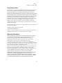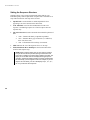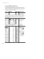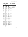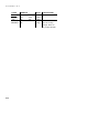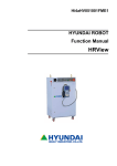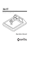
1
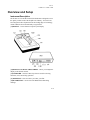
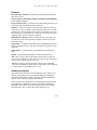
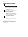
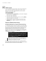
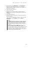
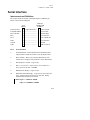
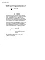
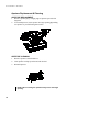
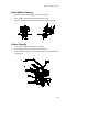
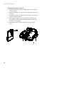
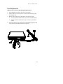
361T
B / W T R A N S M I S S I O N
D E N S I T O M E T E R
Operation Manual
361T
DENSITOMETER
Federal Communications Commission Notice
This equipment has been tested and found to comply with the limits for a Class A digital
device, pursuant to Part 15 of the FCC Rules. These limits are designed to provide
reasonable protection against harmful interference when the equipment is operated in a
commercial environment. This equipment generates, uses, and can radiate radio frequency
energy and, if not installed and used in accordance with the instruction manual, may cause
harmful interference to radio communications. Operation of this equipment in a residential
area is likely to cause harmful interference in which case the user will be required to
correct the interference at his own expense.
NOTE: Shielded interface cables must be used in order to maintain compliance with the
desired FCC and European emission requirements.
Industry Canada Compliance Statement
This Class A digital apparatus complies with Canadian ICES-003.
Cet appareil numérique de la classe A est conforme à la norme NMB-003 du Canada.
AVERTISSEMENT : Des câbles d'interface blindés doivent être utilisés afin de se
conformer aux règlements européens et FCC (USA) sur l'émission.
CE DECLARATION
Manufacturer's Name:
Manufacturer's Address:
Model Name:
Model No.:
X-Rite, Incorporated
X-Rite, Incorporated
Siemensstraße 12b
63263 Neu-Isenburg • Germany
Phone: +49 (0) 61 02-79 57-0
Fax: +49 (0) 61 02 -79 57-57
Densitometer
361
Directive(s) Conformance:
EMC 89/336/EEC LVD 73/23/EEC
RoHS/WEEE
X-Rite products meet the Restriction of Hazardous Substances (RoHS)
Directive 2002/95/EC and European Union – Waste Electrical and
Electronic Equipment (WEEE) Directive 2002/96/EC. Please refer to
www.xrite.com for more information on X-Rite’s compliance with the
RoHS/WEEE directives.
361T
DENSITOMETER
CAUTION: To prevent electrical shock. DO NOT remove cover. No user
serviceable parts inside. Refer servicing to qualified service personnel.
ADVERTENCIA: Para evitar un choque eléctrico, NO QUITE el
recubrimiento del aparato. No hay ninguno componente reparable de
usuario, dentro del aparato. Consulte un técnico calificado para servicio o
arreglo.
AVVERTIMENTO: Per evitare una scossa elettrica, non staccare la
coperta del apparecchio. C'è nessuno componenti riparabili d'utente,
interno del apparecchio. Consultare un tecnico qualificato per servizio o
manutenzione.
VORSICHT: Diese Abdeckung darf nicht entfernt werden. Sie schützt vor
elektrischem Schock. Sie deckt auch keine vom Benutzer zu wartenden
Teile ab. Mit notwendigen Wartungen wenden Sie sich bitte nur an
autorisiertes Fachpersonal.
ATTENTION: Pour prévenir un choc électrique, ne pas enlever le
couvercle. Aucune pièce se trouvant á l’intérieur n’est réparable par
l’utilisateur. Toute réparation doit être adressée à du personnel compétent.
CAUTION: For continued protection against risk of fire, replace only with
same type Time Delay fuse.
ADVERTENCIA: Para evitar el peligro de incendio en el caso de
funcionamiento defectuoso del fusible de retrasar, es preciso reemplazarlo
con un fusible del mismo tipo
AVVERTIMENTO: Per evitare il pericolo di un incendio nel caso di
funzionamento difettoso del fusibile di ritardare, rimpiazzarlo solamente
con un fusibile dello stesso tipo.
VORSICHT: Für fortgesetzten Schutz gegen Feuer, ersetzen Sie die
Verzögerungssicherung nur mit einer vom gleichen Typ.
ATTENTION: Pour éviter les risques d’incendie, ne remplacer le fusible à
retard qu’avec un fusible du même type.
ii
361T
DENSITOMETER
Table of Contents
1. Overview and Setup.......................................................................... 1-1
Instrument Description....................................................................................1-1
Features...........................................................................................................1-3
Unpack and Inspect.........................................................................................1-3
Apply Power and Display Angle Adjustment .................................................1-4
Display (EL) Backlighting ..............................................................................1-4
2. User Interface .................................................................................... 2-1
Key Description ..............................................................................................2-1
FUNCTION ...............................................................................................2-1
COLOR ......................................................................................................2-1
ZERO ..........................................................................................................2-1
Function Selection ..........................................................................................2-2
Color Selection ...............................................................................................2-3
Reference and Base Entry...............................................................................2-4
Density Reference Entry Via Keyboard......................................................2-4
Density Reference Entry Via Measurement................................................2-4
Base Entry...................................................................................................2-5
Measurement Procedure - General..................................................................2-5
Display Messages ...........................................................................................2-5
311 Emulation.................................................................................................2-6
3. Measurement Procedures ................................................................ 3-1
Density Function.............................................................................................3-1
DENSITY MEASUREMENT ....................................................................3-1
DENSITY DIFFERENCE MEASUREMENT ...........................................3-1
+DOT Function...............................................................................................3-1
+DOT MEASUREMENT...........................................................................3-1
-DOT Function................................................................................................3-2
-DOT MEASUREMENT............................................................................3-2
Sequence (Disabled from factory) ..................................................................3-2
4. Calibration ......................................................................................... 4-1
General Information........................................................................................4-1
Frequency of Calibration ............................................................................4-1
Density Calibration Check ..........................................................................4-1
Density Calibration Procedure ........................................................................4-1
Dot Area Calibration Procedure......................................................................4-2
N-Factor Adjustment Procedure .....................................................................4-3
Quick CAL™ Procedure.................................................................................4-4
iii
361T
DENSITOMETER
5. Mode Selection.................................................................................. 5-1
General Information........................................................................................5-1
x10 ON/OFF ...................................................................................................5-1
I/O Port Selection............................................................................................5-2
Setting the Sequence Structure .......................................................................5-4
Read Lamp ON/OFF.......................................................................................5-6
6. Serial Interface .................................................................................. 6-1
Interconnect and Definition ............................................................................6-1
Serial Output ...................................................................................................6-2
Serial Input Commands...................................................................................6-2
Instruction Format...........................................................................................6-3
Internal RAM Data Addresses ........................................................................6-9
External RAM Data Addresses .....................................................................6-10
7. Maintenance ...................................................................................... 7-1
General............................................................................................................7-1
Exterior Cleaning............................................................................................7-1
Aperture Replacement & Cleaning .................................................................7-2
APERTURE REPLACEMENT ..................................................................7-2
APERTURE CLEANING...........................................................................7-2
Beam Splitter Cleaning ...................................................................................7-3
Optics Cleaning...............................................................................................7-3
Lamp Replacement .........................................................................................7-4
ALIGNMENT CHECK ..............................................................................7-5
Fuse Replacement ...........................................................................................7-7
8. Appendix............................................................................................ 8-1
Technical Specifications .................................................................................8-1
Optional Equipment ........................................................................................8-3
iv
361T
DENSITOMETER
Proprietary Notice
The information contained in this manual is derived from patent and proprietary
data of X-Rite, Incorporated. This manual has been prepared solely for the
purpose of assisting in the use and general maintenance of this instrument.
The contents of this manual are the property of X-Rite, Incorporated and
are copyrighted. Any reproduction in whole or part is strictly prohibited.
Publication of this information does not imply any rights to reproduce or use this
manual for any purpose other than installing, operating, or maintaining this
instrument. No part of this manual may be reproduced, transcribed, transmitted,
stored in a retrieval system, or translated into any language or computer
language, in any form or by any means, electronic, magnetic, mechanical,
optical, manual, or otherwise, without the prior written permission of an officer
of X-Rite, Incorporated.
This instrument may be covered by one or more patents. Refer to the instrument
for actual patent numbers.
Copyright © 2007 by X-Rite, Incorporated
“ALL RIGHTS RESERVED”
X-Rite® is a registered trademark of X-Rite, Incorporated. All other logos, brand names,
and product names mentioned are the properties of their respective holders.
Warranty Information
X-Rite, Incorporated (“X-Rite”) warrants each instrument manufactured to be
free of defects in material and workmanship (excluding battery pack) for a
period of 12 months. This warranty shall be fulfilled by the repair or
replacement, at the option of X-Rite, of any part or parts, free of charge
including labor, F.O.B. its factory or authorized service center.
This warranty shall be voided by any repair, alteration, or modification, by
persons other than employees of X-Rite, or those expressly authorized by X-Rite
to perform repairs, and by any abuse, misuse, or neglect of the product, or by use
not in accordance with X-Rite’s published instructions.
X-Rite reserves the right to make changes in design and /or improvements to its
products without any obligation to include these changes in any products
previously manufactured. Correction of defects by repair or replacement shall
constitute fulfillment of all warranty obligations on the part of X-Rite.
THIS WARRANTY IS EXPLICITLY IN LIEU OF ANY OTHER
EXPRESSED OR IMPLIED WARRANTIES, INCLUDING ANY IMPLIED
WARRANTY OF MERCHANTABILITY OR FITNESS FOR ANY
PARTICULAR PURPOSE. THIS WARRANTY OBLIGATION IS LIMITED
TO REPAIR OR REPLACEMENT OF THE UNIT RETURNED TO X-RITE
OR AN AUTHORIZED SERVICE CENTER FOR THAT PURPOSE.
v
361T
DENSITOMETER
This agreement shall be interpreted in accordance with the laws of the State of
Michigan and jurisdiction and venue shall lie with the courts of Michigan as
selected by X-Rite, Incorporated.
vi
361T
DENSITOMETER
1.
Overview and Setup
Instrument Description
The X-Rite 361T is a B/W Transmission densitometer designed to meet
the quality control needs of the Graphic Arts industry. Your 361T has
been integrated with components from the leading edges of technology,
which X-Rite has been internationally recognized for.
[1] DISPLAY - is an 8-character Liquid Crystal Display.
[2] DISPLAY CONTRAST ADJUSTMENT - allows you to adjust the
display to the desired contrast.
[3] KEYBOARD - consists of three keys that are used for selecting
functions, color, and zeroing operation.
[4] APERTURE - is the area where you center your film.
[5] READ BUTTON - used to lower the Read Head when taking
readings.
1-1
CHAPTER
ONE
[6] READ HEAD - is the component that contains the optics which
comes in contact with your film when taking measurements.
[7] POWER SWITCH - turns the unit ON (1) and OFF (0).
[8] VOLTAGE SELECTION SWITCH - selects 115V or 230V
operation.
[9] FUSE HOLDER - holds the proper fuse.
[10] POWER INPUT - is where the 115V/230V AC line cord plugs in.
[11] REFLECTION HEAD INPUT - is used to connect optional
Reflection Head (see "Optional Equipment" in Chapter 8).
[12] I/O PORT - is used for RS232 bi-directional serial
communications.
1-2
OVERVIEW
AND
SETUP
Features
Electronic Filter Selection - eliminates the problems that mechanical
filter wheels create.
Large Liquid Crystal Display and Electroluminescent Backlighting allows optimum legibility.
Larger and Fewer Keys - which have been functionally placed for ease
of operation and to cut down operator confusion.
Sequence - allows for a setup of a measurement routine to meet the job
requirements. Once a sequence structure has been setup, the 361T will
automatically select the function for each step, then advance to the next
step, step by step. (A maximum of 36 steps) x10 provides an extra digit
of display when extreme resolution is required.
RS232 Interface & RCI - (Remote Control Interface) provides a twoway interface for use with computerized quality control systems and
electronic printers.
Lamp Timer - if enabled, automatically turns OFF Reading lamp after 2
hours of instrument non-use. This will extend the life expectancy of the
read lamp.
Ortho and UV - responses allow measurements on a broad range of
films.
Density - provides density and density difference measurements.
+Dot - allows positive dot measurements with zeroing to a Base Dot.
+Dot can be calculated for a Base equal to 0% Dot or can be adjusted to
a value equal to a known Dot size (ex. 3%).
−Dot allows negative dot measurements with zeroing to a Base Dot.
−Dot can be calculated for a Base equal to 100% Dot or can be adjusted
to a value equal to a known Dot size (ex. 97%).
Unpack and Inspect
After removing the instrument from the shipping carton, inspect it for
damage. If any damage has occurred during shipping, immediately
contact the transportation company. Do not proceed with installation
until the carrier’s agent has inspected the damage.
Your instrument was packaged in a specially designed carton to assure
against damage. If shipment is necessary, the instrument should be
packaged in the original carton. If the original carton is not available,
contact X-Rite to have a replacement carton shipped to you.
1-3
CHAPTER
ONE
Apply Power and Display Angle Adjustment
NOTE: If the unit has been stored in an abnormal (cold)
environment, DO NOT apply power to the unit until it has sat for
several hours in a normal environment (10-30°C / 50-86°F).
CAUTION: For safety and unit stability, do not modify line cord
provided with this instrument. Connect to a grounded 3-wire
receptacle.
1.
Ensure that the proper operating line voltage is selected
(slide switch to 115 V or 230 V as necessary). Plug the
female end of the Power Cord into the back of the 361T,
and the other end into the wall outlet.
NOTE: When voltage setting is changed, the proper fuse, fuse
carrier, and line cord must be used. 115 VAC [Fuse SE24-0060,
Fuse Carrier SE71-05, Cord SD33-07] or 230 VAC [Fuse SE490030, Fuse Carrier SE71-06, Cord SD33-08]
2.
3.
4.
Set the Display Angle Adjustment to a midway setting.
Set the power switch to "1" (ON). Adjust the Display
Angle until the data in the display can best be seen at your
line of sight.
Upon power up, the unit will display the software date
code. Next, the unit will perform a self-test, and if
everything is ok, "TST Pass" will be displayed.
NOTE: If the unit does not pass the self-test, an error message
will be displayed, indicating the probable cause (Refer to
"Display Messages" in Chapter 2).
5.
After the unit passes the self-test, the unit will
automatically return to the last function performed (ex.
DEN, +DOT, -DOT).
Display (EL) Backlighting
This feature backlights the display for use in reduced room lighting.
The Electroluminescent (EL) Backlighting turns OFF after 10 minutes
of instrument non-use, and turns back ON when a measurement is taken
or any key is depressed.
1-4
361T
DENSITOMETER
2.
User Interface
Key Description
The Keyboard consists of three key switches, the [FUNCTION] d key,
the [COLOR] c key, and the [ZERO] dc key.
•
FUNCTION
Selects Density, +Dot, and −Dot.
NOTE: Sequence function is disabled from the factory, and will
not be displayed during function selection. If you want
Sequence enabled refer to "Setting the Sequence Structure" in
Chapter 5.
•
Decreases numeric values when used with [ZERO] key.
•
Depressed together with [COLOR] to enter Calibration or
Modes.
•
COLOR
Selects either Ortho or UV Filters during normal operation.
•
Increases numeric values when used with [ZERO] key.
•
Depressed together with [FUNCTION] to enter Calibration or
Modes.
•
•
ZERO
Zeros density or Dot during a measurement.
Used in conjunction with [FUNCTION] or [COLOR] to
numerically enter a value.
NOTE: If you get lost while selecting functions or don't know
exactly where you are during a certain procedure. PRESS THE
[FUNCTION] KEY as many times as it takes until you get back
to a main level function (Den, +Dot, or −Dot).
2-1
CHAPTER
•
TWO
DISPLAY CONTRAST
Rotate the wheel to the back (+) to increase contrast or to the
front (-) to decrease contrast.
Function Selection
The [FUNCTION] key normally selects between one of three functions;
DEN, +DOT, or -DOT. They are sequentially selected with each
momentary depression of the [FUNCTION] key. Once the function you
want is displayed, wait for the 361T to automatically drop into the
function selected (approximately a 2 second waiting period). At this
point, the previous measurement is displayed.
Displayed
Function
Density
DEN
wait 2 sec.
c #.##D
color
value
+Dot
+DOT
wait 2 sec.
-DOT
wait 2 sec.
c ## %
-Dot
c ##
If the Sequence Function is activated (see "Setting the Sequence
Structure" in Chapter 5), SEQUENCE will be displayed between -DOT
and DEN.
2-2
USER
INTERFACE
NOTE: If DEN is the only function that can be activated, refer to
"311 Emulation" to turn it Off.
Color Selection
The [COLOR] Key selects one of two colors, Ortho or UV. They are
alternately selected with each depression of the [COLOR] key. "o" is
displayed for Ortho and "u" for Ultraviolet.
Each depression of the [COLOR] key will
alternately display "o" (Ortho) or "u"
(Ultraviolet).
o
u
o
2-3
CHAPTER
TWO
Reference and Base Entry
Reference values are values, which are subtracted from each density
measurement to display a density difference value. Base values are
values, which cause +Dot or −Dot to display a predetermined Dot size
when zeroed to a base dot or film base fog.
Density Reference Entry Via Keyboard
1.
2.
3.
Depress [FUNCTION] key repeatedly [FUNCTION] until "DEN" is
displayed.
Select color by depressing the [COLOR] key.
Hold [ZERO] down (thru step 4).
•
4.
5.
"REF" is displayed.
• Reference value is displayed.
Enter Ref value using the [FUNCTION] key to decrease value or
[COLOR] key to increase value. (Depress both to reset to zero.)
Release keys.
Depress [FUNCTION] to return to normal operation.
Density Reference Entry Via Measurement
Momentarily depress [ZERO] while measuring area to be Zeroed
(Nulled) out.
1.
2.
3.
Repeatedly depress [FUNCTION] until "DEN" is displayed.
Select color by depressing [COLOR].
Measure the density to be zeroed, and keep the [READ] button
depressed (thru Step 4).
•
2-4
4.
"Density value of density being measured" is
displayed.
Press [ZERO] key.
5.
• "Zero density" is displayed.
Release the [READ] button and [ZERO] key.
USER
INTERFACE
Base Entry
The Base value is usually set to 0% for +DOT and 100% for -DOT, or
adjusted to a value equal to a known minimum (base) dot size (ex. 3%
for +Dot or 97% for −Dot).
1.
2.
3.
4.
5.
Repeatedly depress [FUNCTION] key until "+Dot" or "−Dot" is
displayed.
Select color by depressing [COLOR].
Hold [ZERO] key down (thru step 4).
• Base value is displayed.
Enter Base value using the [FUNCTION] key to decrease or the
[COLOR] key to increase value. (depress both to reset to zero.)
Release keys.
Depress [FUNCTION] to return to normal operation.
Measurement Procedure - General
1.
2.
3.
4.
Select desired function and color.
Center area being measured over center of aperture.
Lower reading head by pressing on Read button. "READING" will
be displayed during a measurement cycle.
Release Read Button after data is displayed.
NOTE: "INVALID" will be displayed if the Read button is not
depressed for enough time.
Display Messages
MESSAGE
REASON
BATTERY:
The memory backup battery has failed. The Lithium
battery needs replacement by a qualified technician.
INVALID:
The Read button was held down too short causing an
invalid measurement. If “INVALID” appears after the
Read button was held down for the proper length of
time or if “READING” is displayed an abnormal
length of time while taking a measurement, possible
causes are defective Side Sensor, Reading Head
Assembly, or Transmission PCB.
LAMP FAIL:
The Read Lamp has failed its intensity test. The Read
Lamp should be examined and possibly replaced.
When this happens, you can get out of this error.
2-5
CHAPTER
TWO
MESSAGE
REASON
condition (if lamp was OK or replaced) by pressing
[FUNCTION], then [COLOR], then [FUNCTION].
MEM TEST:
The memory in the unit is going through an extended
memory check. If “MEM TEST” remains on the
display, the display PCB needs to be replaced.
MEM LOST:
Calibration of the unit has been lost and recalibration
is necessary.
NEED CAL:
Unit needs full length calibration.
uP FAIL:
The microprocessor has failed its memory test. The
display PCB should be replaced by a qualified
technician.
311 Emulation
When 311 EMULATION is set to ON, the 361T will simulate the I/O
port and some operational characteristics of the X-Rite 311/RS
densitometer. The modes are setup as follows: x10 OFF, I/O Port [RCI
ON, RPT OFF, P5 OFF, BAUD 1200, HDR OFF, DPT OFF, CR,
COMP OFF, and X OFF], SEQUENCE OFF, and READ LAMP ON.
The operational characteristics are setup as follows: DENSITY
operation is the only function that is accessible, and MODES are
disabled.
NOTE: To access 311 emulation, the AC power must be
turned off and then turned back on with the function and
color keys held depressed thru the self test until "311 off"
is displayed.
Described below is the procedure for setting the 311 Emulation.
1.
2.
3.
4.
2-6
Turn OFF power to the 361T.
Depress [FUNCTION] and [COLOR] keys together (than turn on
A.C Power) until "311 OFF" is displayed.
Each depression of the [ZERO] key will alternate between 311 ON
and 311 OFF.
Depress [FUNCTION] one time to return to normal operation.
361T
DENSITOMETER
3.
Measurement Procedures
Density Function
The DEN function allows you to take density and density difference
measurements. The procedure for each of these are as follow.
DENSITY MEASUREMENT
1. Repeatedly depress [FUNCTION] key until "DEN" is displayed.
Previous density is displayed.
2. Select color (ortho or ultraviolet).
3. Measure film. Density value is displayed.
DENSITY DIFFERENCE MEASUREMENT
1. Repeatedly depress [FUNCTION] key until "DEN" is displayed.
Previous density is displayed.
2. Select color (ortho or ultraviolet).
3. Enter a reference value. Refer to "Reference and Base Entry" in
Chapter 2 for entry of reference via the keyboard, or via a
measurement.
4. Measure film that is to be compared. Density difference value is
displayed.
+DOT Function
The +DOT function allows positive dot measurements with zeroing to a
Base Dot value. +Dot can be calculated for a Base equal to 0% Dot or
can be adjusted to a value equal to a known Dot size (ex. 3%). +DOT is
normally used for positive films.
+DOT MEASUREMENT
1. Repeatedly depress [FUNCTION] until "+DOT" is displayed.
Previous Dot value is displayed.
2. Select color (ortho or ultraviolet).
3. Zero unit to a Base Dot or Base Fog of film, by pressing [ZERO]
while measuring this area of the film.
4. Measure the Dot area on the film. +Dot value is displayed.
3-1
CHAPTER
THREE
-DOT Function
−Dot allows negative dot measurements with zeroing to the Base Dot
value. −Dot can be calculated for a Base equal to 100% or can be
adjusted to a value equal to a known Dot size (ex. 97%). -DOT is
normally used for negative films.
-DOT MEASUREMENT
1. Repeatedly depress the [FUNCTION] key until "-DOT" is displayed.
Previous Dot value is displayed.
2. Select color (ortho or ultraviolet).
3. Zero unit to a Base Dot or Base Fog of film, by pressing [ZERO]
while measuring this area of the film.
4. Measure the film. −Dot value is displayed. Repeatedly depress
[FUNCTION] until "+DOT" is displayed. Previous Dot value is
displayed.
Sequence (Disabled from factory)
The Sequence function allows a setup of a measurement sequence to
meet the job requirements. Once a sequence structure has been setup
(see "Setting the Sequence Structure" in Chapter 5 for setup procedure)
the 361T will automatically select the function and advance to the next
step, step by step. Once in the Sequence function, a depression of the
Read button advances to the next step. However, the 361T can
increment or decrement thru the steps by depressing and holding dc
[ZERO] key and then depressing d [FUNCTION] key to decrement or
c [COLOR] key to increment.
IMPORTANT! The Density/Dot value for each sequence step is
displayed during the measurement (Read button depressed).
When the Read button is released, the display shows the next
step to measure. If you desire to view the Density/Dot value for
the last step measured, press the [ZERO] key to view it, and
then press [ZERO] again to return.
NOTE: During sequence operation, look at the display and
make sure each measurement is correct before releasing the
Read button to proceed to the next step.
The example Sequence procedure below shows a sequence that was
setup using two steps, and it starts out at step1. When entering sequence,
the function will always start at the lowest step enabled.
3-2
MEASUREMENT
1.
2.
3.
4.
5.
6.
PROCEDURES
Repeatedly depress the [FUNCTION] key until "SEQUENCE" is
displayed. (If sequence does not appear, refer to "Setting the
Sequence Structure" in Chapter 5). Function, Color, and Step to be
measured first is displayed.
Select color (ortho or ultraviolet).
Take first measurement.
Measurement value and Step number are displayed while the
[READ] button is held down. After Read button is released, Step 2
is displayed.
Take second measurement.
Measurement value and step number are displayed while the read
button is held down.
* After release of the Read button, the display will ask if you want
to print out. If yes, press [COLOR]. If no, press [ZERO] or
[FUNCTION].
NOTE:
1) "PRINT? C" will only be displayed if the Sequence printout
procedure in Mode Setup is selected for CLASS or ORDER. It
will automatically print out after each measurement (step) if
EACH was selected. (See "Setting the Sequence Structure" in
Chapter 5.)
2) When Step 00 is setup for "ZERO 00" the unit will use the
same Zero (reference) value for Den, +Dot, or −Dot.
3) The Zero (reference) value is common to all Density steps, all
+Dot steps, and/or all −Dot steps, for step zero (00) only. On
any other step, if the unit is zeroed, the zeroing only applies for
the function that was selected for that step.
3-3
CHAPTER
3-4
THREE
361T
DENSITOMETER
4.
Calibration
General Information
The X-Rite 361T is designed for long life and extremely stable
measurements. To follow good quality control practice, you should
check Density and Dot calibration periodically to verify measurement
accuracy and proper operation of your unit. To verify and perform
Density calibration, a calibrated transmission reference has been
provided. The transmission reference has a five step gray scale ranging
from approximately 0.06D (step 1) to 4.0D (step 5).
Frequency of Calibration
Under normal operating conditions, the instrument should be calibrated
once a week or when instrument displays a message regarding
calibration.
Density Calibration Check
To check density calibration, first zero the unit, and then measure the
"cal" step on the transmission reference. If the measurement is within
.02D of the densities specified, the unit is properly calibrated. If not, the
unit must be recalibrated (see "Density Calibration Procedure" in
Chapter 4).
NOTE: On the transmission reference, step 4 (CAL) is used for
calibration, and steps 1, 2, 3, and 5 are used for checking the
linearity of the unit.
Density Calibration Procedure
Handle the transmission reference at the edges only. Fingerprints or any
other foreign substances on the measurement area will cause errors.
Attempts to dust or clean the surface with anything other than a soft
camel hair brush may change densities. Minimize change by storing in a
dark, cool, dry place.
1.
2.
3.
4.
Depress [FUNCTION] and [COLOR] keys at the same time until "N
Dcal Y" is displayed.
Depress [ZERO] for YES.
Depress [FUNCTION] for NO.
Calibration Hi value for Ortho is displayed. (If value is correct skip
to Step 6.)
4-1
CHAPTER
FOUR
5.
Enter the correct Cal Hi value for Ortho (as marked on the step
tablet) by pressing and holding dc (ZERO) down and using the
d (FUNCTION) key to decrease value or the c (COLOR) key to
increase value. Then release both keys.
6. Depress [COLOR] key to select Ultraviolet cal value. Cal Hi value
is displayed for Ultraviolet. (If value is correct skip to Step 8.)
7. Enter the correct Cal Hi value for Ultraviolet (as marked on the step
tablet) by depressing and holding dc (ZERO) down and using the
d (FUNCTION) key to decrease value or the c (COLOR) key to
increase value. Then release both keys.
8. Depress [COLOR] key.
9. Remove all film from table and take measurement. "Cal LO" value
is displayed during measurement.
10. Release Read button.
11. Take measurement of Cal Step on the Step tablet. "CAL HI" value
is displayed during measurement. Display automatically returns
back to "DEN" upon release of the Read button.
Dot Area Calibration Procedure
NOTE: This calibration procedure only pertains to units with
software date code 8718 and greater. The dot area calibration
will allow for more accurate dot area measurements. When
calibrating dot area it is important that a dot reference with a
true 50% dot area (i.e. UGRA Plate Control Wedge, RIT
Microline Resolution Target, etc.) is used for proper calibration.
Shown below is the procedure for Dot Area calibration. Density
calibration needs to be performed or verified first.
4-2
1.
Depress [FUNCTION] and [COLOR] keys at the same time until "N
Dcal Y" is displayed.
2.
Press [FUNCTION] to indicate No, you do not want to calibrate
density.
3.
Press [ZERO] to indicate Yes, you want to calibrate dot area.
4.
Press [COLOR] key to select color (ortho or ultraviolet).
5.
Measure base area on the film. After releasing Read button, "READ
50%" is displayed.
6.
Measure 50% dot on the film. After releasing Read button, display
returns to normal +Dot operation.
INSTRUMENT
CALIBRATION
N-Factor Adjustment Procedure
NOTE: Transmission dot "N-factor" is calibrated at the factory
and therefore should not require user calibration.
However, if calibration to a particular 50% dot reference is desired, it is
important that a reference with a true 50% dot area (e.g.; UGRA Plate
Control Wedge, RIT Microline Resolution Target, etc.) is used. Enter
the factory preset N-factors for ortho and u.v. below for future reference.
ortho N-factor_________ u.v. N-factor_________
The N-factor for dot can be adjusted by performing the following
procedure.
1.
2.
3.
4.
5.
6.
7.
8.
9.
Press the [FUNCTION] and [COLOR] keys simultaneously until "N
Dcal Y" displays.
Press the [FUNCTION] key to bypass Density Calibration
procedure.
Press the [ZERO] key to enter Dot Calibration procedure.
Select ortho (o) or ultraviolet (u) by pressing the [COLOR] key.
Measure base area on film. "READING" is displayed followed by
"0%" dot value. After the Read button is released, "Read 50%" is
displayed.
Press the [COLOR] key to enter N-Factor menu.
Press the [COLOR] key to toggle between ortho (o) or ultraviolet
(u), if required.
Adjust the N-Factor by pressing and holding the [ZERO] key.
Repeatedly press the c (COLOR) key to increase value or the
d (FUNCTION) key to decrease value.
After adjustments, press the [FUNCTION] key to exit N-factor.
4-3
CHAPTER
FOUR
Quick CAL™ Procedure
Quick Cal™ provides you with an easy means of re-establishing zero
(Calibration Low). This method is included because the zero
(Calibration Low) is the major factor of drift over a period of time.
1.
2.
3.
4.
5.
4-4
Depress [FUNCTION] and [COLOR] keys at the same time until "N
Dcal Y" is displayed.
Depress [ZERO] for YES.
Depress [ZERO] for YES.
Remove all film from table, and take a measurement.
Release the Read button, display will automatically return back to
DEN.
361T
DENSITOMETER
5.
Mode Selection
General Information
The Mode function controls four factors: x10 On/Off, I/O Port set-up,
Sequence setup, and Read Lamp On/Off. Modes come preset from the
factory as follows:
1. x10 [OFF]
3. SEQUENCE
SQ
[OFF]
2. I/O PORT
COL
[ADJ]
RCI
[ON]
SQ
[ORDER]
RPT
[OFF]
SIZE [36]
P5
[OFF]
SKIP [00] (Skip Step 0)
BAUD [1200]
FUNCTION STEP [all set
HRD [OFF]
to DEN]
DPT
[ON]
COMP [ON] 4. READ LAMP [ON]
CR
[LF]
To change any of the above settings refer to the setup procedures in
Chapter 5 which follow: x10 On/Off, I/O Port Setting, Sequence Structure,
and Read Lamp.
NOTE: If no Modes can be accessed in Mode Selection, refer to
"311 Emulation" in Chapter 2 to turn Off 311 Emulation.
x10 ON/OFF
When activated, the x10 function allows an extra digit to be displayed
when extreme resolution is required.
1.
2.
3.
4.
5.
6.
Depress [FUNCTION] and [COLOR] keys at the same time until "N
Dcal Y" is displayed.
Depress [FUNCTION] for NO.
Depress [FUNCTION] for NO.
Depress [ZERO] for YES.
Depress [ZERO] to turn x10 ON or OFF.
Press [FUNCTION] four (4) times to return to normal operation.
5-1
CHAPTER
FIVE
I/O Port Selection
Your X-Rite 361T comes equipped with a serial port that allows data to
be transmitted and/or received by the 361T to/from an external device.
The 361T can be externally controlled by the Serial Input Commands
discussed in "Serial Input Commands" in Chapter 6.
•
RCI [Remote Control Input] enables or disables the ability to
externally control the 361T via the I/O port.
•
RPT ON/OFF [Reference Print] enables or disables the Reference
values during print-out.
•
P5 determines the status of Pin 5 of the I/O port. Pin 5 may be set to
OFF, BUSY, or CTS (Clear To Send). Note: Pin 5 should normally
be set to OFF when Pin 5 is not going to be used.
•
BAUD RATE determines the output rate (characters per second) of
the I/O port. Available outputs are: 300, 600, 1200, 2400, 4800,
9600, and OFF.
•
HDR [Header] enables or disables the header (DEN, +DOT, -DOT,
TRANS, and x10) during print-out. When set to ON, the header will
print. When set to OFF, the header will not print.
•
DPT [Decimal Point] enables or disables the decimal point during
print-out. When set to ON, the decimal point will print. When set to
OFF, the decimal point will not print.
•
CR / CR LF [Carriage Return / Carriage Return, Line Feed] varies
the delimiter at the end of each line of data. When set to CR, just a
Carriage Return is sent at the end of a line of data. When set to CR
LF, a Carriage Return and a Line Feed are sent at the end of a line
of data.
•
COMP [Computer output] varies the output format of the I/O port.
When set to ON, a Space will appear after each group of data
values. When set to OFF, no space will appear after each group of
data values.
NOTE: <SP>=Space, <CR>=Carriage Return, and
<LF>=Line Feed
•
5-2
X ON / X OFF - not available at this time.
MODE
SELECTION
The procedure for setting the I/O port options is shown below.
1. Depress [FUNCTION] and [COLOR] keys at the same time until "N
Dcal Y" is displayed.
2. Depress [FUNCTION] for NO.
3. Depress [FUNCTION] for NO.
4. Depress [ZERO] for YES.
5. Depress [FUNCTION], "↓ I/O Y" is displayed.
6. Press [ZERO] to advance to RCI. Each depression of the [ZERO]
key will alternate between RCI OFF and RCI ON.
7. Press [FUNCTION] to advance to FUNCTION RPT. Each
depression of [ZERO] key will alternate between RPT ON and RPT
OFF.
8. Press [FUNCTION] to advance to P5. Each depression of [ZERO]
key will select between P5: Busy, CTS, or OFF.
9. Press [FUNCTION] to advance to BAUD. Each depression of
[ZERO] will page thru BAUD 2400, 4800, 9600, OFF, 300, 600,
and 1200.
10. Press [FUNCTION] to advance to FUNCTION HDR. Each
depression of [ZERO] key will alternate between HDR ON and
HDR OFF.
11. Press [FUNCTION] to advance to FUNCTION DPT. Each
depression of [ZERO] key will alternate between DPT OFF and
DPT ON.
12. Press [FUNCTION] to advance to FUNCTION COMP. Each
depression of [ZERO] key will alternate between COMP OFF and
COMP ON.
13. Press [FUNCTION] to advance to FUNCTION CR. Each depression
of [ZERO] key will alternate between CR LF and CR.
14. Press [FUNCTION] four (4) times and the 361T returns to normal
operation.
5-3
CHAPTER
FIVE
Setting the Sequence Structure
Sequence allows you to setup a measurement routine that fits your
individual quality control requirements. Sequence has a maximum of 36
steps and a function for each step can be selected.
•
SQ OFF/ON is used to disable or enable SEQUENCE from
appearing as an active function in the main menu.
•
COL ADJ/LOC is used to allow ADJustment of what color
response is used during sequence or to LOCk sequence into one
response only.
•
SQ order/class/each is used to determine the method for printout of
data.
1.
2.
3.
order – Transmit all data by sequential step number.
class – Transmit data by type of function. (i.e. DEN first,
then +Dot, then −Dot)
each – Transmit data after each step is measured.
•
SIZE 1-36 sets the size of the sequence from 1 to 36 steps.
•
FUNCTION Den/+Dot/−Dot/Skip sets the function that will be
used for each sequence step.
NOTE: SKIP is used for steps that you don’t want to measure,
but you still want the step number (during measurement and
print out) to correlate to the actual step numbers of the film. The
steps you set as SKIP will not be displayed during Sequence
operation; instead the display will skip over them and designate
the actual step you are support to read. For example, if you set
steps 2 and 5 as SKIP, your 361T will display step 1, 3, 4, 6, 7,
etc. as you advance thru sequence.
5-4
MODE
SELECTION
The procedure for setting Sequence structure is shown below.
1.
2.
3.
4.
5.
6.
Depress [FUNCTION] and [COLOR] keys at the same time until "N
DcalY" is displayed.
Depress [FUNCTION] for NO.
Depress [FUNCTION] for NO.
Depress [ZERO] for Yes.
Depress [FUNCTION] two (2) times "↓ SEQ Y" is displayed.
Depress [ZERO] to advance to SQ. Each depression of [ZERO] will
alternate between SQOFF and SQ On.
NOTE: If "←SQ OFF" is displayed, depressing the
FUNCTION key will cause the display to return to Step 4.
7.
8.
9.
10.
11.
12.
13.
14.
15.
Depress [FUNCTION] to advance to COL. Each depression of
[ZERO] will alternate between COL LOC and COL ADJ.
Depress [FUNCTION] to advance to SQ. Each depression of [ZERO]
will page thru SQ class, SQ each, SQ order.
Depress [FUNCTION] to advance to SIZE. Hold dc (ZERO)
pressed down and press d (FUNCTION) to decrease or c (COLOR)
to increase the amount of steps required (1 thru 36).
Depress [FUNCTION] to advance to DEN 00 (Step 00).
Repeatedly press the [COLOR] key until "←SKIP 00" is displayed.
(This will cause Step 00 to be skipped during operation.) Or select
[←ZERO 00] to enable a special step 0 for zeroing the
densitometer to the film base.
Hold dc (ZERO) pressed down and press c (COLOR) once to
advance to Step 1. Release keys.
Repeatedly press [COLOR] key to select the function (DEN, +DOT,
-DOT, or SKIP) that will be required for the step.
Hold dc (ZERO) pressed down and press c (COLOR) once to
advance to Steps 2, 3, 4, etc.
Depress [FUNCTION] three (3) times and 361T returns to normal
operation.
5-5
CHAPTER
FIVE
Read Lamp ON/OFF
This feature allows the densitometer to automatically turn the Read lamp
OFF after 2 hours of instrument non-use. Having the Transmission lamp
turn OFF will extend the time before lamp replacement. The lamp will
turn back ON after any key is pressed, the Read button is pressed, or any
"M, P, U, or Y" RCI command has taken place. LAMP ON causes the
lamp to stay ON as long as the unit is powered on. LAMP OFF causes
the lamp to turn OFF after two hours of non-use of the Transmission
unit.
1.
2.
3.
4.
5.
6.
7.
5-6
Depress [FUNCTION] and [COLOR] keys at the same time until "N
Dcal Y" is displayed.
Depress [FUNCTION] for NO.
Depress [FUNCTION] for NO.
Depress [ZERO] for YES.
Depress [FUNCTION] three (3) times to advance to "LAMP ON".
Each depression of [ZERO] will alternate between LAMP OFF and
LAMP ON.
Press [FUNCTION] one (1) time to return to normal operation.
361T
DENSITOMETER
6.
Serial Interface
Interconnect and Definition
The 25-pin connector used for serial input/output is a DB25S type.
Below is the connection diagram.
TYPICAL
361T
COMPUTER
DB25S
W/DB25
Frame Ground
1 —Signal Direction— 1 Frame Ground
Transmitted Data 2 ———————— 3 Receive Data
Received Data
3 ———————— 2 Transmit Data
RTS
4 ————————
No Connection
Pin 5
5 ———————— 4 RTS or DTR (20)
DSR
6 ————————
No Connection
Ground
7 ———————— 7 Ground
DTR
20 ———————— 6 DSR or CTS (5)
Pin #
Term Definition
2
Transmitted Data – Data transmitted from the densitometer
with parameters (baud rate, format) set by the densitometer.
3
Received Data – Data received by the densitometer from
outside source using the same parameters as the densitometer.
4
RTS (Request To Send) – Logic 0 only.
5
PIN 5 – if set to CTS = Logic 0 active, if set to BUSY = 1
active, and if set to OFF = IGNORE.
6
DSR (Data Set Ready) – Logic 0 active.
20
DTR (Data Terminal Ready) – Logic 0 active (On Line) and
Logic 1 during: Power Off, Power Up, Self Test, during
measurements, and when service RCI.
Note: Logic 1 = +.8VDC to –25VDC
Logic 0 = +2.25VDC to +25VDC
6-1
CHAPTER
SIX
A typical interconnection (in its simplest form) between the 361T and a
computer is shown below.
Receive Data
Transmit Data
Ground
COMPUTER
361T
W/DB25
2 ———————— 3 Receive Data
3 ———————— 2 Transmit Data
7 ———————— 7 Ground
Serial Output
The data format that is transmitted from the 361T is determined by the
I/O PORT options found in "I/O Port Selection" in Chapter 5.
Serial Output Note – Data transmitted by the 361T shall
have one start bit (Logic 0), 7 bits of ASCII, one parity bit
set to zero, and then one stop bit (Logic 1).
Serial Input Commands
Your 361T is equipped with an input which allows the 361T to be
controlled or monitored remotely. Every function which can be
performed by the 361T (plus a few special functions not activated by the
keyboard) can be activated via the serial input. This Remote Control
Interface is covered by U.S. Patent 4,591,978.
Basically, the Remote Control Input (RCI) format consists of a series of
characters (a command string) sent to the 361T in an ASCII FORMAT
with a Carriage Return or Line Feed at the end of each command string
to act as a delimiter. The 361T then acts on that command. The serial
input buffer of the 361T, upon receiving its first command string
character, sends a "Buffer Full" interrupt to the 361T microprocessor.
The 361T microprocessor then halts all normal operation and dedicates
itself to receiving and responding to remove control command strings.
Normal execution is returned to upon receiving a GO command via the
serial input.
Serial Input Notes – 1) Data transmitted by the 361T shall
have one start bit (Logic 0), 7 bits of ASCII, one parity bit
set to zero, and then one stop bit (Logic 1). 2) To ensure
proper processing of received data by the 361T, a delay of
50 msec. should be added between every character sent to
the 361T, and a delay of 500 msec. should be added after a
"p", "t", or "u" command.
6-2
SERIAL
INTERFACE
Instruction Format
In general, the format used as the command string for serial input is as
follows:
1
2
3
4
DATA — ADDRESS — ACTION CODE — <LF>
1.
2.
3.
DATA – is a two character hexadecimal code (in ASCII) which is
written to the control register that is being addressed, and is used
during a Write Action only.
ADDRESS – is a one to three character hexadecimal code (in
ASCII) that selects the memory location which will be acted upon.
ACTION CODE – is a single character which is used to define the
Remove Control Action as shown below:
NOTE: ALL ACTION CODES FOR THE 361T MUST BE SENT
AS CAPITAL (UPPERCASE) LETTERS.
G
[Go] is the ASCII character sent to the 361 to release it to operate as
instructed after the "LF" (or "CR" is received.
NOTE: The reason for the "G" command is that when the
361T senses that data is being received on the serial input,
it stops normal operation and only allows the serial input to
modify or monitor keys and control registers, until a "G"
Action Code is given to return the 361T to normal
operation.
I
[INTERROGATE] reads the external RAM memory from the first
Address to the last Address, and sends the Data value(s) out the
Transmit line of the I/O port in the following format: ##CR(LF).
The first and last Address must both be designated a 3 hexadecimal
characters in the command string. If the last Address is not sent or is
a lower Address than the first Address, then only the first Address is
read.
Command String
# # # # # # I——Action Code
│ │
Last Address First Address
6-3
CHAPTER
J
SIX
[KEY ENABLE] is used to enable or disable all keys (with the
exception of the Read button) from altering the operation of the
unit. This switch enables or disables the keys by the 361T receiving
the following as the Address and Action Code portions of the string:
1J______ Keys enabled
________ 1 = keys enable
0 = keys disable
NOTE: This switch will reset itself to "keys enable" each
time the unit is turned on by applying power or by
executing a "P" command from RCI.
K
[KEY DEPRESSION] is used to enable the 361T to transmit a K
plus a number to indicate which key has been depressed. This
switch is enabled or disabled by the 361T receiving the following as
the Address and Action Code portion of the command string. The
"KEYS ENABLED" switch (J) must be set to disable for the "K"
code to function.
1K______ Keys enabled
________ 1 = keys enable
0 = keys disable
When enabled, the 361T will transmit the following when a key is
pressed.
K1 = Function key
K2 = Color key
K3 = Zero key
K4 = Read button
In addition, a Carriage Return <CR> or a <CR> and a Line Feed
<LF> will be sent after KX depending on how CR / CR LF is set in
Modes.
NOTE: This switch will reset itself to KEY DEPRESSED
DISABLE" each time the unit is turned on by applying
power or by executing a "P" command for RCI.
6-4
SERIAL
INTERFACE
L
[LOAD] writes Data to the external RAM memory location
Address. Data must be designated as 2 hexadecimal characters and
the Address location as 3 hexadecimal characters, in the command
string.
I——Action Code
Command String
#####
│ │
Data Address
M [MEASUREMENT] causes the 361T to take a measurement.
N
[NULL] causes a Reference measurement if either the Read button
is pressed or if a measurement is being forced by use of the "M"
Action Code.
P
[POWER UP RESET] causes the 361T to do a software reset.
Q
[QUERY] transmits a single display character to the serial port, as
designated by a single hexadecimal character (equal to the character
position in the display) preceding the Action Code "Q".
Character
Position ___
R
361T Display
#Q___ Action Code
0
1 2 3 4 5 6 7
____ Display Position
[READ] reads the Address location of the microprocessor's internal
memory, and causes the 361T to serially output in ASCII Format 2
hexadecimal characters representing the binary data specified by the
(2 hexadecimal characters) Address portion of the command string.
Command String
S
# # R——Action Code
│
Address
[STRING] is used to display a string. The 361T will display
whatever data it receives via the serial port, starting from the
Display Address location, as designated by a single hexadecimal
character preceding the action code "S".
361T Display
#S——
Action Code
——
0
Display Position
1
2
3
4
5
6 7
6-5
CHAPTER
T
SIX
[BAUD] is used to change the baud rate of the 361T. The unit must
receive the following as the address and the action codes portion of
the command string:
XXT—— Action Code
———— 03 = 300 baud
06 = 600 baud
0C = 1200 baud
18 = 2400 baud
30 = 4800 baud
60 = 9600 baud
After the 361T receives the first delimiter (#4 in the command
string), it automatically performs a "g LF" (#5 and #6 in command
string). The unit should not receive an additional "g<LF>".
A command string with a "T" as the action code with no address
preceding it, sent to the 361T at the correct baud rate will force the
361T to transmit the proper hexadecimal code for its baud rate.
U
[UPDATE] command must be received by the 361T after any write
commands to internal or external RAM Memory and after any "Y"
action codes. This command forces the unit to update the data
written to RAM or process a "Y" action code and forces a position
within a function as determined by an address preceding the "U"
command. The 361T must receive the following as the address and
action code portion of the command string.
1U———— Action Code
—————
1 = forces display to data level
0 = forces display to beginning of
function
V
[VERSION] transmits the software date code (that is displayed on
the character displayed during power-up), and a <CR> or
<CR><LF> to the serial port.
X-RITE 361 VER. XXXX (XXXX = Date Code)
6-6
SERIAL
INTERFACE
W [WRITE] writes Data to the Address location of the
microprocessor's internal RAM memory. This action causes the
361T to replace the contents of the microprocessor's RAM location,
designated by the (2 hexadecimal characters) Address portion of the
command string, with 8-bits of binary data, designed by the (2
hexadecimal characters) Data portion of the command string.
X
Y
W——Action Code
## ##
│ │
Data Address
[TRANSMIT] sends the present contents of the 361T display (8
characters) plus a <CR> or <CR><LF> to the serial port.
[FUNCTION] is used to select the function of the 361T. The unit
must receive the following as the address and the action code
portion of the string command.
#Y——— Action Code
————
1 = DEN
2 = +DOT
3 = –DOT
4 = SEQUENCE
5 =X
6 =X
7 =X
8 = QCalTM
9 = Extended cal
A "U" command must also be received by the unit following a "Y"
command.
6-7
CHAPTER
Z
SIX
[DISPLAY ENABLE] is used to enable or disable the display from
being updated with data that occurs from normal operation. This
switch enables or disables the display by the 361T receiving the
following as the address and action code portion of the command
string:
1Z——— Action Code
————
1
0
= display enable
= display disable
NOTE: This switch will reset itself to "Display enable" each
time the unit is powered up by applying power or by
executing a "P" command from RCI.
4
6-8
<LF> (Line Feed) is an ASCII Line Feed used as a delimiter and
tells the 361T to perform the preceding command and unless that
command was "G", wait for the next command. (Note: A <CR> can
be sent instead of a <LF> if necessary.)
SERIAL
INTERFACE
Internal RAM Data Addresses
The Internal RAM Data Addresses are used to access parameters not
handled by action codes. The following list covers the most commonly
used parameters, their addresses, and a bit map for each address. In
addition, there are several notes that indicate the limitations and cautions
that must be followed in using these addresses.
NAME
BIT #
Mode (Address 2AH)
Enabled when Bit = 1
0
1
2
3
4
5
6
7
Color
(Address 2CH)
Enable when Bit = 1
0
1
2
:
7
0
1
2
3
4
5
6
7
I/O
(Address 2E)
FUNCTION
Sequence Unlocked
x10
Lamp 2 Hour Shut-off
RCI on
Seq. print format Bit 2
311
SEQ Color Lock
Seq. print format Bit 1
Seq. Print Format
BIT 1 BIT 2
Seq. Each
1 X
Seq. Order 0 0
Seq. Class
0 1
Ortho
UV
0
:
0
Pin5: CTS = 1, BUSY = 0
Pin5: OFF = 1
DPT ON = 1
Baud Off = 1
CR LF = 1
COMP ON = 1
RPT ON = 1
HDR ON = 1
X = Don't Care
6-9
CHAPTER
SIX
External RAM Data Addresses
The External RAM Data Addresses are used to access data values,
reference values, and other values. The following list covers the most
commonly used addresses. In addition, there are several notes that
caution the user and must be followed.
NAME
*Memory
Reset
DATA PARAMETERS
1 Byte Write a 00 to address
plus a "P" command
to reset system.
*USE THIS ADDRESS WITH CAUTION: Writing to this address
will force system reset, and the unit will clear all memory locations.
Calibration and data will be lost. Make sure that a system reset is
what is desired.
ORTHO UV
DEN Data 0C0,0C1 0C2,0C3 2 Bytes Least significant bit
REF
0D0,0D1 0D2,0D3
(LSB) = .001D
+DOT Data 0E8,0E9 0EA,0EB
LSB = .1%
Ref
0F8,0F9
0FA,0FB
-DOT Data* 118,119
11A,11B
LSB = .1%
Ref*
120m121 122m123
*-DOT values are subtracted from 100%
Values are in
ex. Display = 99% -DOT Data = 1%
hexadecimal.
Sequence
Functions
Sequence Function
Step 0,1
228
, 229
1 Byte Step Zero = Byte
Step 2,3
22A
, 22B
1 Byte
80H=Skip
Step 4,5
22C
, 22D
1 Byte
81H=Zero
Step 6,7
22E
, 22F
1 Byte
Step 8,9
230
, 231
1 Byte Sequence Function
Step 10,11 232
, 233
1 Byte Step 1-36 = Byte
Step 12,13 234
, 235
1 Byte
80H=Skip
Step 14,15 236
, 237
1 Byte
81H=DEN
Step 16,17 238
, 239
1 Byte
84H=+DOT
Step 18,19 23A
, 23B
1 Byte
88H=-DOT
Step 20,21 23C
, 23D
1 Byte
Step 22,23 23E
, 23F
1 Byte
Step 24,25 240
, 241
1 Byte
Step 26,27 242
, 243
1 Byte
Step 28,29 244
, 245
1 Byte
Step 30,31 246
, 247
1 Byte
Step 32,33 248
, 249
1 Byte
6-10
ADDRESS
0C8
SERIAL
NAME
Step 34,35
Step 36,27
Sequence
Data
Step 0
Step 1
Step 2
Step 3
Step 4
Step 5
Step 6
Step 7
Step 8
Step 9
Step 10
Step 11
Step 12
Step 13
Step 14
Step 15
Step 16
Step 17
Step 18
Step 19
Step 20
Step 21
Step 22
Step 23
Step 24
Step 25
Step 26
Step 27
Step 28
Step 29
Step 30
Step 31
Step 32
Step 33
Step 34
Step 35
Step 36
ADDRESS
24A
, 24B
24C
, 24D
ORTHO
250,251
254,255
258,259
25C,25D
260,261
264,265
268,269
26C,26D
270,271
274,275
278,279
27C,27D
280,281
284,285
288,289
28C,28D
290,291
294,295
298,299
29C,29D
2A0,2A1
2A4,2A5
2A8,2A9
2AC,2AD
2B0,2B1
2B4,2B5
2B8,2B9
2BC,2BD
2C0,2C1
2C4,2C5
2C8,2C9
2CC,2CD
2D0,2D1
2D4,2D5
2D8,2D9
2DC,2DD
2E0,2E1
UV
252,253
256,257
25A,25B
25E,25F
262,263
266,267
26A,26B
26E,26B
272,273
276,277
27A,27B
27E,27F
282,283
286,287
28A,28B
28E,28F
292,293
296,297
29A,29B
29E,29F
2A2,2A3
2A6,2A7
2AA,2AB
2AE,2AF
2B2,2B3
2B6,2B7
2BA,2BB
2BE,2BF
2C2,2C3
2C6,2C7
2CA,2CB
2CE,2CF
2D2,2D3
2D6,2D7
2DA,2DB
2DE,2DF
2E2,2E3
INTERFACE
DATA PARAMETERS
1 Byte
2 Bytes
2 Bytes
2 Bytes
2 Bytes
2 Bytes
2 Bytes
2 Bytes
2 Bytes
2 Bytes
2 Bytes
2 Bytes
2 Bytes
2 Bytes
2 Bytes
2 Bytes
2 Bytes
2 Bytes
2 Bytes
2 Bytes
2 Bytes
2 Bytes
2 Bytes
2 Bytes
2 Bytes
2 Bytes
2 Bytes
2 Bytes
2 Bytes
2 Bytes
2 Bytes
2 Bytes
2 Bytes
2 Bytes
2 Bytes
2 Bytes
2 Bytes
2 Bytes
Values are in hexadecimal. Least
significant bit =
.001D or 1%
6-11
CHAPTER
SIX
NAME
CAL HI
ORTHO
UV
SKIP
PROMPTS
6-12
ADDRESS
05A
066
700
DATA PARAMETERS
, 05B
, 067
2 Bytes
2 Bytes
1 Byte
Write 80 for skip
prompts. Write 00
for prompts (default)
361T
DENSITOMETER
7.
Maintenance
General
The X-Rite 361T is covered by a one-year limited warranty (excluding
lamps) and should be referred to the factory or authorized service center
for repair within the warranty period. Attempts to make repairs within
this time frame may void the warranty.
Always verify instrument calibration to assure proper instrument
operation. Make sure all connections are properly made.
X-Rite provides a factory repair service to their customers. Because of
the complexity of the circuitry all circuitry repairs should be referred to
the factory or an authorized service center.
X-Rite will repair any 361T past warranty. Shipping costs to the factory
or authorized service shall be paid by the customer and the instrument
shall be submitted in its original carton, as a complete unaltered unit.
AS A ROUTINE MAINTENANCE PROCEDURE, replace the read
lamp after every 1200 hours of operation. This allows approximately a
half year of operation (based on an 8 hour operating shift per five days a
week). Failure to do so may cause erroneous density readings. X-Rite
has also provided you with an extra Transmission read lamp. This lamp
should only be replaced by a qualified service repair person.
Exterior Cleaning
Never use any liquids (water or solvents) to clean the exterior of the
instrument. Whenever required, the exterior of the instrument can be
wiped clean with a dry, lint-free cloth.
7-1
CHAPTER
SEVEN
Aperture Replacement & Cleaning
APERTURE REPLACEMENT
1. Remove aperture [1] by wedging edge of aperture upwards with
fingernail.
2. To reinstall aperture, insert aperture into target opening [2] making
sure aperture is pressed flush against surface.
APERTURE CLEANING
1. Remove aperture as described above.
2. Clean aperture with Q-tip moistened with alcohol.
3. Reinstall aperture.
NOTE: When cleaning the aperture always cover the target
opening.
7-2
MAINTENANCE
Beam Splitter Cleaning
1.
2.
3.
Remove aperture as described in "Exterior Cleaning".
Clean residue from Beam Splitter [1] with dry Q-Tip.
Remove dust and lint by lightly blowing air into target opening.
Optics Cleaning
1.
2.
3.
Cover aperture [1] with small piece of plastic.
Grasp reading head assembly [2] and lift upwards.
Clean residue and dust from optics [3] with Q-tip slightly moistened
with alcohol.
7-3
CHAPTER
SEVEN
Lamp Replacement
AS A ROUTINE MAINTENANCE PROCEDURE, replace the read
lamp after every 1200 hours of operation. This allows approximately a
half year of operation (based on an 8 hour operating shift per five days a
week). Failure to do so may cause erroneous density readings. X-Rite
has also provided you with an extra Transmission read lamp. This lamp
should only be replaced by a qualified service repair person.
1.
2.
3.
4.
5.
6.
7.
7-4
DISCONNECT LINE CORD FROM POWER RECEPTACLE.
Set unit upside down and remove larger bottom cover [1] by
unscrewing the three screws [2] located in front portion of cover.
Unplug lamp connector from circuit board (located under small
bottom cover).
Remove lamp assembly by unscrewing the two Phillips-head screws
[4] (with washers) from bottom of lamp assembly then discard lamp
assembly [5].
Fasten new lamp assembly [5] in place with two Phillips- head
screws [4], and two flat washers supplied with lamp.
Plug lamp connector into circuit board.
Check lamp alignment. (See following page.)
MAINTENANCE
ALIGNMENT CHECK
Set unit upright, plug line cord into wall receptacle, and turn power
switch to "ON" position.
9. Locate your transmission reference (used for calibration) and center
step "3" or "CAL" over aperture. (Use 3mm aperture.)
10. Look at the light coming through the round aperture. The lamp's
filament will appear as a square in the middle of the aperture.
11. If lamp is properly aligned: Unplug line cord, turn unit upside
down, and then fasten bottom cover in place with three screws
removed in step 2. If lamp is not properly aligned, proceed with
Steps 12 thru 16.
8.
7-5
CHAPTER
SEVEN
ALIGNMENT CHECK (continued)
12. Unplug line cord then loosen two Phillips-head screws 6 in bottom
of lamp assembly.
13. Set front half of unit over edge of table, then plug line cord into wall
receptacle.
14. Carefully move lamp assembly until lamp filament is centered with
aperture (see Steps 9 and 10).
15. After alignment, unplug line cord and tighten two Phillips-head
screws [6] in bottom of lamp assembly WITHOUT moving lamp
assembly out of alignment.
16. Fasten bottom plate in position with three screws removed in
Step 2.
7-6
MAINTENANCE
Fuse Replacement
[DISCONNECT LINE CORD BEFORE SERVICING]
1.
2.
3.
Insert flatblade screwdriver into slot of fuse cap [1].
Push in and turn counterclockwise one-half turn until fuse [2] and
fuse cap pop out.
Remove fuse from fuse cap and replace with same type fuse.
•
115vac operation (600ma 250v 3AG Slo-blo, P/N SE24-0060)
•
4.
230vac operation (300ma 250v Type T Time Lag, P/N SE4900300)
Insert fuse into fuse cap, insert fuse into fuseholder [3], push-in and
turn clockwise one-half turn until fuse cap locks.
7-7
CHAPTER
7-8
SEVEN
361T
DENSITOMETER
8.
Appendix
Technical Specifications
PARAMETER
Display
Measuring Range
Density
% DOT Area
Reference Range
All Except DOT
+DOT (Fringe)
-DOT (Fringe)
Calibration
Zero
Slope
Dot
Accuracy
Ortho, Visual
2,3mm aperture
1mm aperture
U.V.
3mm aperture
Repeatability
Ortho, Visual
2,3mm aperture
1mm aperture
U.V.
3mm aperture
Interinstrument Agreement
Zero Stability
Slope Stability
Warm-up Time
Measuring Geometry
Illumination
Light Collection
Aperture Angle
Incident Light
Measuring Area Diameter
SPECIFICATION
8 character LCD, 9.4mm H w/ EL
backlighting
0 - 6.0D
0 - 100% (pos & neg)
All possible values measured
-10% to +69%
+31% to +110%
Digital w/ lithium battery backup
Auto
Yes, for Density
For 50% Point
±0.02D (0-5.0D), ±1% (5.0-5.5D),
±2% (5.5-6.0D)
±.02D (0-4.5D), ±1% (4.5-5.0D)
±0.02D (0-3.5D), ±1% (3.5-4.0D)
±0.01D (0-5.0D), ±2% (5.0-5.5D),
±3% (5.5-6.0D)
±.01D (0-4.5D), ±1% (4.5-5.0D)
±0.01D (0-3.5D), ±1% (3.5-4.0D)
±.02D, ±2% (0-5.0D)
±.02D max per 8hr
±1% max per 1 year
2 min. (U.V. = 5 min.)
Per ANSI PH2.19, ISO5/2
0 degrees
Diffusing surface
Approx. ±5 degrees
1, 2, 3mm
.5mm optional, P/N 319-40-005
8-1
CHAPTER
EIGHT
PARAMETER
Response
Orthochromatic
Ultraviolet
Visual (optional)
Color Temp. of Light Source
IR Sensitivity
Ambient Interference
Interface
SPECIFICATION
X-RITE Ortho
X-RITE U.V.
X-RITE Visual
Approx. 2850K
D > 4.0 (U.V.)
D decreases <.25%
Bidirectional,
Serial RS-232-C DTE
300, 600, 1200, 2400,
Baud Rate
4800, 9600
T 90-130VAC, 50-60Hz
Voltage Requirements
TX 180-260VAC, 50-60Hz
80VA max
Power Requirements
≤76%
Operating Relative Humidity
+10º to +40ºC
Operating Temp. Range
(+50º to +104ºF)
-20º to +50ºC
Storage Temp Range
(-4º to +122ºF)
[cm] 15.2 x 33. x 43.5
Dimensions (HxWxD)
[in]
6. x 13.1 x 17.1
[kg] 8.64 [lb] 19.0
Gross Weight
[kg] 7.95 [lb] 17.5
Net Weight
UL 3101-01
Safety
C22.2, No. 1010-1-92
2000m
Altitude
Pollution Degree 2
IEC 664
Category 2
Installation Type
Indoor only
Usage
Part 15, Class A, Digital Device
FCC
ICES-003 Issue 2, Revision 1
Industry Canada
EN50081-1:1992
International
Class B Generic Emission Standard
EN50082-1:1992
Generic Immunity Standard
Specifications and design appearance subject to change without notice.
8-2
APPENDIX
Optional Equipment
There are six models of the 361 Reflection Head that are available to
interface with the 361T Transmission unit.
Model 361G-06
Model 361GS-06
Model 361G/LP-06
Model 361E-06
Model 361ES-06
Model 361E/LP-06
Color Reflection Densitometer w/ G and T
Response, 3.4mm Aperture
Color Reflection Densitometer w/ G and T
Response, 1.7mm Aperture
Color Reflection Densitometer w/ G and T
Response, 3.4mm Aperture, & Polarizing Filter
Color Reflection Densitometer w/ E and N
Response, 3.4mm Aperture
Color Reflection Densitometer w/ E and N
Response, 1.7mm Aperture
Color Reflection Densitometer w/ E and N
Response, 3.4mm Aperture, & Polarizing Filter
NOTE: The Reflection Heads listed come with all necessary
cables, instructions, and accessories to connect to the
361T.
G - represents the normal X-Rite Graphics Arts wideband response. It is
similar to Status T response but has more sensitivity to denser
yellow inks.
T - represents ANSI Status T Computerized Color Response™
(CCRTM), for use with the *T-Ref color reference.
E - represents a European response which uses a 47B filter for yellow.
N - represents Narrow Band Glass Interference Type Computerized
Color ResponseTM. This response is computer corrected and
designed for use with process inks on paper. Measurements other
than process inks may yield answers with slight discrepancies.
* T-Ref is a trademark of GCA (Graphic Communication Association).
8-3
CHAPTER
EIGHT
Interface Cables available:
P/N 361-69
Transmission/Reflection Interface Cable
P/N 361-83
DB25P to 10 Circuit Modular Interface Cable
(Available Adaptors for 361-83 cable above)
P/N 418-70
DB25P DCE (Null Modem) Interface Adaptor
P/N 418-71
DB25S DCE (Null Modem) Interface Adaptor
P/N 418-80
DB25P DTE (Normal) Interface Adaptor
P/N 418-81
DB25S DTE (Normal) Interface Adaptor
P/N 418-90
DB9P Interface Adaptor
P/N 418-91
DB9S Interface Adaptor
P/N 309-149
Whisper Printer Interface Cable
P/N 309-249
Seiko Printer Interface Cable
Optics Assemblies available:
P/N 361V-23
8-4
Visual/U.V. Optics Assembly
Corporate Headquarters - USA
4300 44th Street SE
Grand Rapids, Michigan 49512
Phone 1 800 248 9748 or 1 616 803 2100
Fax 1 800 292 4437 or 1 616 803 2705
Corporate Headquarters - Europe
Althardstrasse 70
8105 Regensdorf
Switzerland
Phone (+41) 44 842 24 00
Fax (+41) 44 842 22 22
Corporate Headquarters - Asia
Room 808-810
Kornhill Metro Tower, 1 Kornhill Road
Quarry Bay, Hong Kong
Phone (+852) 2 568 6283
Fax (+852) 2 885 8610
Please visit www.xrite.com for a local office near you.
P/N 361T-500 Rev. JJ