1
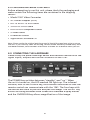
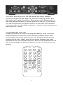
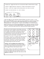
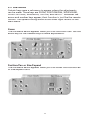
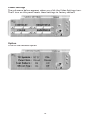
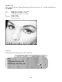
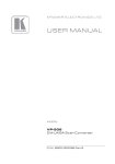
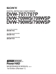
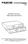
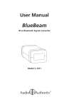
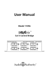
User Manual
Model 1361
High Definition to
Standard Definition
Video Converter
2
Table Of Contents
1.0
Introduction . . . . . . . . . . . . . . . . . . . . . . . 4
2.0
Specifications
3.0
Checking Package Contents . . . . . . . . . . . . . . . 6
4.0
Connecting The Hardware
5.0
Operating The Unit . . . . . . . . . . . . . . . . . . . 7
6.0
Troubleshooting . . . . . . . . . . . . . . . . . . . .
14
7.0
Limited Warranty . . . . . . . . . . . . . . . . . . .
14
8.0
Regulatory Compliance . . . . . . . . . . . . . . . .
15
9.0
Contact Information . . . . . . . . . . . . . . . . . .
15
. . . . . . . . . . . . . . . . . . . . . . 5
3
. . . . . . . . . . . . . . . 6
1.0 INTRODUCTION
Thank you for purchasing this 1361 Video Converter from Audio
Authority. The 1361 has many uses, but the vital need it answers
is in a mixed signal distribution system. Many satellite receivers
and cable boxes do not offer simultaneous output on YPbPr and
composite ouputs. To distribute the same signal to TVs with HD
component inputs as well as TVs with composite or S-Video inputs,
a quality down-converter is required. Model 1361 converts an HD
component or PC video signal to standard analog NTSC or PAL
video. Output is either composite and S-Video or standard definition
component (YCbCr) format, with a simultaneous HD pass-thru. Audio
Authority also offers an extensive line of audio and video switchers,
converters and distribution amps available for purchase online at
www.audioauthority.com.
1.1 Liability Statement
Every effort has been made to ensure that this product is free of
errors. Audio Authority cannot be held liable for the use of this
hardware or any direct or indirect consequential damages arising
from its use. It is the responsibility of the user of the hardware
to check that it is suitable for his/her requirements and that it is
installed correctly. All rights reserved. No parts of this manual may
be reproduced or transmitted by any form or means electronic
or mechanical, including photocopying, recording or by any
information storage or retrieval system without the written consent
of the publisher.
Audio Authority reserves the right to revise any of its hardware and
software following its policy to modify and/or improve its products
where necessary or desirable. This statement does not affect the
legal rights of the user in any way.
All third party trademarks and copyrights are recognized. The Audio
Authority logo and Double A logo are the registered Trademarks
of Audio Authority. All other trademarks are the property of their
respective holders.
1.2 FEATURES
•
•
•
•
•
•
Switchable PC or HDTV inputs up to (1600x1200@60Hz) and 1080i
NTSC or PAL outputs, composite, s-video or component
Loop through inputs - both PC and HDTV
Adjustable aspect ratio and image scaling: pan, position and zoom
Remote control with on screen display
PC in/out cable, component, composite and s-video output cables
4
2.0 SPECIFICATIONS
Video Input Connectors
HDTV Component (YPbPr)
Three RCA female (loops to output)
PC
One HD-15 female (loops to output)
Video Output Connectors
Composite
One RCA female
S-Video
4-pin Mini-DIN female
Component (YPbPr)
Three RCA female
HDTV Video
PC
Input Signal Characteristics
HDTV Inputs Resolution Supported
480i, 480p, 576i, 576p, 720p, 1080i
PC Resolutions Supported
VGA, SVGA, XGA, SXGA, UXGA
Output Signal Characteristics
Composite, S-Video
NTSC or PAL, interlaced
Component
YCbCr
Control Methods
Local
Push buttons on unit + OSD
Remote
IR remote control w/OSD + RS-232
Mechanical
Size (H-W-D)
2”x8”x6” (50x204x155mm)
Weight (Net)
2.2 lbs. (1kg)
Warranty
Limited Warranty
1 Year, Parts and Labor
Power Requirements
External AC Adaptor
5 VDC @ 2A
Regulatory Approvals
Model 1361
FCC, CE
AC Power Adaptor
UL, CE, CSA
Accessories Included
AC Power Adapter (USA)
User Manual
HD-15 to HD-15 VGA cable
3-RCA to 3-RCA cable
RCA to RCA component cable
S-Video cable
IR remote control
Application Software CD
5
3.0 CHECKING PACKAGE CONTENTS
Before attempting to use this unit, please check the packaging and
make certain the following items are contained in the shipping
carton:
• Model 1361 Video Converter
• AC Power Adapter (USA)
• HD-15 to HD-15 VGA cable
• 3-RCA to 3-RCA cable
• RCA to RCA component cable
• S-Video cable
• IR remote control
• Application Software CD
Note: Please retain the original packing material should the need ever arise to return
the unit. If you find any items are missing, contact Audio Authority immediately. Have
the Model Number, Serial Number and Invoice available for reference when you call.
4.0 CONNECTING THE HARDWARE
Please study the panel drawings below and become familiar with the
signal inputs, outputs and control locations on the 1361.
The POWER key switches between “standby” and “on“. When
the unit is turned on, the LED marked ON lights up. The infrared
window, next to the POWER key, must remain unblocked so that the
remote control can communicate with the 1361. The four keys with
the arrows are used to position and pan the image. The ASPECT key
allows switching between wide screen and standard display modes
and the OVERSCAN key allows magnification of the image.
6
The inputs and outputs on the rear panel are clearly marked.
Connect the appropriate cables to the inputs making certain that
the cables are in good condition. The power switch (upper right in
the view above) removes or applies power to the unit. If the switch
is in the OFF position, the power switch on the front has no effect.
The switch next to the power connector is used to switch between PC
input and HDTV input.
5.0 OPERATING THE 1361
These instructions will focus on using the remote, since it has the
complete array of functions, while the front panel buttons offer
only the basic functions. Most of the 1361 buttons can be quickly
understood by their labels, and the on-screen display gives more
explanation for the complex functions. Refer to the explanations on
the following pages to become familiar with all of the keys on the
remote.
OUTPUT
1
2
3
CONTRAST
4
5
6
BRIGHT
7
8
9
COLOR
ASPECT
SHARP
ZOOM
FREEZE
POWER
OVERSCAN
V-RESET
DEFAULT
POS/PAN
SIZE/EXP
SYS-RESET
NTSC/PAL
COLORBAR
7
OVERSCAN: Toggles between over-scanned and under-scanned normal image
OUTPUT: Toggles between composite, S-Video and component outputs
FREEZE: Causes the image currently diplsayed on the screen to freeze
POWER: Switches between “on” and “standby”
FREEZE
POWER
OVERSCAN
OUTPUT
1
2
3
CONTRAST
4
5
6
BRIGHT
The four keys in the corners shown below (ZOOM, ASPECT, POS/
PAN, and
SIZE/EXP)
control
picture manipulations and the arrowed
7
8
9
COLOR
keys work in conjunction with these four keys to do the actual
manipulations. The DEFAULT key (in the middle of the arrow key
SHARP
ASPECT
ZOOM returns the
matrix)
following
parameters to factory presets: Zoom,
Position, Size and Picture adjustments. Descriptions of the ZOOM,
V-RESET
DEFAULT
ASPECT, POS/PAN,
and SIZE/EXP
functions are shown
below.
OVERSCAN
OUTPUT
FREEZE
POS/PAN
SIZE/EXP
NTSC/PAL
POWER
ZOOM: Press the ZOOM key to enlarge a section of
the picture. Press it again to return to normal image
SYS-RESET
size.
When the ZOOM key isCOLORBAR
pressed, the picture
is divided into nine zones. Pressing one of the
numbered keys selects the portion of the image (the
zone) you want to enlarge. The ARROW keys can
also be used to move across the image.
1
2
3
CONTRAST
4
5
6
BRIGHT
7
8
9
COLOR
POS/PAN: If the unit is in under-scan mode, pressing
this button allows the user to position the underscanned image anywhere on the raster using the
arrow keys. If the unit is in the over-scan mode,
pressing this key allows the user to pan the overscanned image using the arrow keys.
ZOOM
ASPECT
SHARP
ASPECT: This key toggles three modes. Full is
the regular 4:3 aspect mode. The second toggle
activates the Pan and Scan mode wherein you can
adjust the image horizontally and vertically. The
final toggle activates the letterbox mode.
SIZE/EXP: When in the under-scan mode, pressing
this button allows the arrow keys to expand or
shrink the image within the monitor’s raster. If the
system is in over-scan mode, the arrow keys set the
degree of overscan.
8
V-RESET
DEFAULT
POS/PAN
SYS-RESET
SIZE/EXP
NTSC/PAL
COLORBAR
CONTRAST, BRIGHTNESS, COLOR & SHARP: These keys
allow adjustment to be made to the labeled signal
parameters. Press one of the keys, then use the arrow keys
to make adjustments.
1
FREEZE
2
3
CONTRAST
5
6
BRIGHT
8
9
COLOR
ASPECT
SHARP
V-RESET: Restores factory default settings to the Contrast,
Brightness Color and Sharpness parameters.
4
NTSC/PAL: Selects the television standard to use on the
1361 output.
7
SYS-RESET: Restores factory presets to all parameters
(Overscan, NTSC, 4:3 Aspect Ratio, Signal Parameters and
CV/SV Output).
COLORBAR: Causes an internally generated color bar signal
to appear on the unit’s outputs.
POS/PAN
POWER
V-RESET
SIZE/EXP
SYS-RESET
NTSC/PAL
COLORBAR
Pinouts for RS-232 Cable
5.1 RS-232 Operation
Software is included to allow control of the
1361 via a computer. The operation under
RS-232 control is explained in the following
pages.
1361
Connector
Pinout
PC Serial
Connector
Pinout
1, NC
1, NC
2, TxD
2, RxD
5.1.1 Installing the Software
3, RxD
3, TxD
• Compatability: Windows 98/ME/2000/XP
4, NC
4, NC
• Place the CD in the drive and execute the
setup.exe function from the CD.
5, GND
5, GND
6, NC
6, NC
• The computer will probably update some
files causing the need to reboot after the
initial setup has finished. If this happens,
reboot and run setup a second time.
7, NC
7, NC
8, NC
8, NC
9, NC
9, NC
• Once fully installed, click the taskbar
menu (Start>Programs>Scan Converter)
to start the RS-232 software.
9
5.2 Main Panel
A main panel appears containing 15 icons that provide the control
functions of the unit (icons 15 through 18 pertain to the application
itself). Click an icon to perform a function.
Refer to the list of numbers below to learn the function of the icons.
2
3
4
5
6
7
14
1
15
16
17
18
8
Icon #
1
2
3
4
5
6
7
8
9
10
11
12
13
14
15
16
17
18
19
9
10
11
12
Function
Connection Status - If gray, there is no connection
Power On Indicator
System Reset
Zoom
Magnifier
Over/Under-scan
Option
Aspect
Pan/Position
Expand/Size
Output Format
Screen Freeze
Video Settings
Prompt Text
Close
Minimize
System Tray
About
RS-232 Com Port in Use
10
13
19
5.3 Sub-Menus
Certain keys cause a sub-menu to appear where the adjustments
can be made. These keys are ZOOM, POSITION/PAN, SIZE/EXPAND,
VIDEO SETTINGS, MAGNIFIER, OPTION, and ABOUT. Wherever the
arrow and number keys appear, their function is just like the remote
control. The upward facing arrow at the lower right returns to the
main menu.
Zoom
The sub-menu below appears when you click the Zoom icon. Use the
arrow keys or the number keys to make adjustments.
Position/Pan or Size/Expand
The sub-menu below appears when you click either the Position/Pan
or Size/Expand icons.
11
Video Settings
The sub-menu below appears when you click the Video Settings icon.
The R icon on this panel resets these settings to factory default.
Option
Click on the desired option.
12
Magnifier
This panel allows the adjustment of picture size. It is only available in
PC mode.
1.5
2.0
S
B
Arrows
X
Magnify the image 1 1/2 times
Magnify the image 2 times
Generate an undersize image
“Big” frame
Image refresh
Close sub-menu
About
Software and firmware information.
13
6.0 TROUBLESHOOTING
If you experience difficulties, check for faulty cables or bad
connections. Unexpected results may also be caused by choosing the
wront output setting. Make sure the input resolution and refresh
rate is within the specification of the 1361 and make sure the output
format selected (composite, S-Video or YCbCr) is correct for the type
of cable and connector being used at the output. Also make certain
that you have selected the correct television standard (NTSC or PAL).
If the problem still persists after trying the above suggestions,
contact the Audio Authority Technical Service department via email:
[email protected], or call 800/322-8346 or 859/233-4599.
7.0 LIMITED WARRANTY
Should any consumer use product from Audio Authority fail due to
defects in materials or workmanship within one year from the date
of the original sale to the end-user, Audio Authority guarantees that
we will replace the defective product at no cost. Freight charges for
the replacement unit will be paid by Audio Authority (Ground service
only). A copy of the invoice showing the item number and date of
purchase (proof-of-purchase) must be submitted with the defective
unit to constitute a valid in-warranty claim.
Units that fail after the warranty period has expired may be returned
to the factory for repair at a nominal charge, if not damaged beyond
the point of repair. All freight charges for out-of-warranty returns
for repair are the responsibility of the customer. Units returned for
repair must have a Return Authorization Number assigned by the
factory.
This is a limited warranty and is not applicable for products which,
in our opinion, have been damaged, altered, abused, misused, or
improperly installed. Audio Authority makes no other warranties
either expressed or implied, including limitation warranties as to
merchantability or fitness for a particular purpose. Additionally,
there are no allowances or credits available for service work or
installation performed in the field by the end user.
14
Warranty Service Procedures
If you suspect a product defect, contact Audio Authority’s Technical
Service Department at 800/322.8346 or 859/233.4599 for assistance in
verifying the problem. If a defect or potential defect is suspected, a
replacement unit will be shipped immediately on a defect-exchange
basis and a Return Authorization Number will be issued for the
return of the defective product. Replacement units are sent out at
the Manufacturer’s Suggested Retail Price which is debited to the
Customer’s Credit Card at the time of shipment. Once we receive
the defective unit back at the factory, it will be evaluated under the
conditions of this warranty and if found to be in-warranty, a full
credit will be issued to the Customer’s Credit Card. Return freight
charges for the defective unit are the customer’s responsibility.
Please contact our Technical Service Department for complete details
concerning all in and out of warranty service matters.
We appreciate your confidence in our products and services and will
always strive to meet or exceed your needs.
8.0 REGULATORY COMPLIANCE
This product complies with the relevant standards for FCC and CE
approval.
The Power Adaptor/Supply has been tested for compliance with UL,
CSA & CE Regulations.
9.0 CONTACT INFORMATION
Should you have questions or require assistance with this product in
areas not covered by this manual, please contact Audio Authority
using the information below.
Audio Authority Technical Service
800/322-8346 M-F 8:30 AM to 5:00 PM, EST
International: 859/233-4599 Fax: 859/233-4510
Send email to: [email protected]
Audio Authority Corporation
2048 Mercer Road
Lexington, Kentucky 40511-1071
USA
15
2048 Mercer Road, Lexington, Kentucky 40511-1071
Phone: 859/233-4599 • Fax: 859/233-4510
Customer Toll-Free USA & Canada: 800/322-8346
Website: http://www.audioauthority.com
752-504
2/06