1
AVIDdirector-M2M
™
Technical Reference Guide
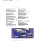
Table of Contents
AVIDdirector-M2M™ Technical Reference Guide .............................................................................................. 3
Overview.................................................................................................................................................... 3
Features..................................................................................................................................................... 3
Hardware Design........................................................................................................................................ 5
WatchDog Timer Technical Notes .............................................................................................................. 9
M2M Application Framework Software Design .......................................................................................... 12
The Configuration files.............................................................................................................................. 20
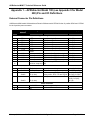
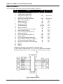
Appendix 1 – AVIDdirector Model 100 (see Appendix 9 for Model 200) Pin and I/O Definitions ........................ 29
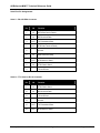
External Connector Pin Definitions............................................................................................................ 29
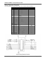
Debug / Expansion Connector .................................................................................................................. 30
Radio Connector ...................................................................................................................................... 31
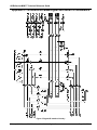
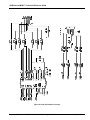
Appendix 2 - AVIDdirector-M2M Digital and Serial I/O Schematics................................................................... 32
Appendix 4 – Sample M2Mlet for Simulation Board.......................................................................................... 36
Appendix 5 - M2MXML TM Version 1.0 Specification....................................................................................... 43
Appendix 6 – Sample M2MApp.ini Configuration File....................................................................................... 43
Appendix 7 – Upgrading the M2M Java Firmware............................................................................................ 46
Appendix 8 – Reprogramming the PSoC Firmware.......................................................................................... 48
Appendix 9 – Model 200 TTL Ports and DB-37 Expansion I/O Connector ....................................................... 50
Appendix 10 – AVIDdirector Jumper Settings .................................................................................................. 54
March 13, 2009
AVIDWireless Confidential
Page 2 of 55
AVIDdirector-M2M™ Technical Reference Guide
AVIDdirector-M2M™ Technical Reference Guide
Overview
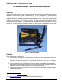
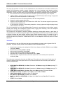
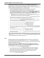
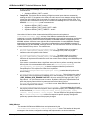
AVIDdirector-M2M is a dedicated wireless telemetry communication device that is capable of being installed in
an industrial environment, to provide communications with a variety of equipment. AVIDdirector-M2M is
designed to operate over any carrier’s network through different replaceable radio cards. AVIDdirector-M2M is a
ruggedized alternative to handheld wireless devices that can easily be broken, lost or stolen. AVIDdirector-M2M
is capable of expanding your telemetry applications by assembling a collection of wireless modems, ruggedized
computers and sensor input / output boards. To simplify the M2M communications and collection features,
AVIDdirector-M2M uses M2MXML1 to interface directly with backend systems and web portals. Each device is
supplied with our M2M Application Framework software that allows a user to implement a wireless solution
directly with your current machinery or sensors without writing embedded software applications on the device.
Figure 1. AVIDdirector-M2M
Features
The principle features of this device are:
1. Uses the Imsys Technologies2 Cjip Java processor. This processor directly executes Java op-codes as
its native machine instruction set without the need for an interpreter or Java to machine code compiler.
This means the executable program size is very small (Java class files are often only 1-4K in size) and
the performance is equivalent to desktop machines.
2. A Sun certified J2ME CLDC environment with extension for serial and parallel device I/O and control. It
supports the connection framework along with PPP, javax.comm serial APIs, watchdog timers and other
enhancements. Up to 128 different threads may be simultaneously executing.
3. It provides bi-directionally communication over any carrier’s network using approved and commercially
available modem modules.
1
See Appendix 5 and http://www.m2mxml.org for further details and specifications.
2
See http://www.imsystech.com for further details on the Cjip and SNAP system
February 5, 2009
©AVIDwireless 2004-2009 All Rights Reserved
Page 3 of 55
AVIDdirector-M2M™ Technical Reference Guide
4. 8 MB of Flash memory for program and persistent data storage, and 8 MB of DRAM memory. Of the 8
MB RAM, up to 6 MB is used for the Java heap, though up to 7 MB may be allocated. Java executables
may be any size up to the amount of RAM or Flash installed.
5. Comes with the M2M Application Framework (M2MApp) preinstalled to implement on-terminal behaviors
as configured by an M2MXML portal. This allows the user to configure each I/O pin and port’s function
and tie it to a device specified by a web portal or other M2MXML server. M2MApp has the concept of an
M2Mlet for the user application and dynamically loadable device I/O drivers.
6. Internal debug / console connector. This allows connecting both an Imsys Developer hardware
debugging pod and a serial terminal console port. The debugging pod provides single step execution,
breakpoints (at either the Java statement or op-code level), data inspection and program download.
7. A “Unix-like” USB console terminal application for development and debugging. This supports most
common Unix and DOS commands along with special command for program loading and transfer.
8. Four high voltage / current (HVC) digital input / output ports. These are designed to control relays and
other industrial automation control systems. These ports will operate at up to 18 VDC at 250 mA or
provide open collector outputs capable of sinking at least 400 mA. They are over voltage and current
protected. Normal operation is 80-180 mA.
9. 22 TTL level (0 to 5 VDC) digital input / output ports. These are designed to control or interface with
other electronic equipment. They can source 8 mA and sink 25 mA. Configurable as 8 Analog (4 Analog
In/Out and 4 Analog In) all are capable of Digital In/Out.
10. Analog input capability to measure input voltages levels up to 10 readings per second. Two of the High
Voltage/Current ports can measure input voltages up to 24 VDC with 12-bit accuracy and the TTL1 to
TTL4 ports can measure input voltages up to 5 VDC with up to 14-bit accuracy, and TTL5, TTL6 can be
configured for 12 bit readings. These may be programmed for higher speed and/or more precise
readings if required.
11. 7 RS-232 lines on DB-9 and DB-37, supporting 1 or 2 serial connections
12. Two of the TTL (1 and 2 See Model 200 TTL Ports and DB-37 Expansion I/O Connector diagram for
complete pin-out descriptions) pins can provide Analog output, driving 25 mA maximum.
13. The TTL5 and TTL6 lines may be switched to support connection with external I2C devices.
14. An external RS232 serial I/O port for bi-directional communication with the target equipment, including
hardware flow control on CTS, RTS, DTR and DTE. +5V is available on this connector to directly power
devices such as GPS, RFID, Barcode and Fingerprint readers.
15. An external TTL level (0 to 5 VDC) serial I/O port for bi-directional communication with target equipment,
including hardware flow control on CTS and RTS. +5V is also supplies on this connector. These lines
(RX2, TX2, CTS2, RTS2) many be directly controlled as four additional general purpose Digital I/O lines,
or Analog input or output (RX2, TX2).
16. Supports extended operation on battery power by providing a low power or “sleep” mode where most
terminal functions are powered off, but the low power mode can be terminated at a pre-set time or by
pre-set activity on one of the two digital input ports.
17. Allows terminal software firmware upgrades by downloading new software over the serial port. A
Windows client can be provided for this task.
18. Real-time clock and calendar with battery backup.
19. Packaged in a fully enclosed case 4.5” x 3.5” x 1.5” with standard industrial connectors for external
antenna (SMA), externally provided 12 volt power, and serial/digital/analog I/O using standard
connectors. The case will provide a mechanism for mounting using either extra mounting flanges or
bolts.
20. Two status LEDs; one to indicate application behavior and the second for radio communications status.
21. 128 bytes of EEPROM storage for device configuration parameters.
22. Low noise linear regulators that do not to interfere with distant radio signals and are monitored by a
temperature sensor to prevent overheating.
February 5, 2009
©AVIDwireless 2004-2009 All Rights Reserved
Page 4 of 55
AVIDdirector-M2M™ Technical Reference Guide
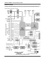
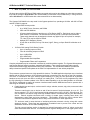
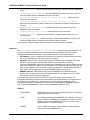
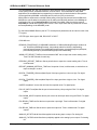
Hardware Design
The device contains two processors: an Imsys Cjip Java processor and a Cypress Microsystems PSoC (System
On a Chip). The Cjip handles the application and network functions and the PSoC the hardware interfacing.
A block diagram of the system is as shown:
Figure 2 AVIDdirector-M2M Architecture
February 5, 2009
©AVIDwireless 2004-2009 All Rights Reserved
Page 5 of 55
AVIDdirector-M2M™ Technical Reference Guide
The Imsys Cjip processor is unique in that it implements the Java instruction set as its native machine code,
avoiding the performance penalty normally associated with Java interpreters and allowing real-time,
deterministic behavior needed by embedded applications. The processor includes IEEE 454 floating-point
acceleration. The Cjip processor offers far more functionality than traditional J2ME based devices by allowing:
a. Direct execution of Java op-codes without the overhead or performance penalty of an interpreter.
b. 8 MB of RAM for application heap and data storage and 8 MB Flash persistent storage for programs
and data (this could be expanded in a custom design)
c. Simultaneous execution of multiple applications, each with multiple threads
d. Support for multiple network connections.
e. Support for both the J2ME CLDC and a subset of the J2SE APIs. This includes support for javax.comm,
network and direct hardware I/O.
f. An internal debug connector to allow setting breakpoints, viewing registers and single stepping through
code execution on the device.
The Cjip is responsible for running the M2Mapplication Framework, communicating over the wireless network,
telemetry data storage and management, system startup, logging and monitoring. From the developer’s
perspective it is the prefect processor for this device.
The Cypress PSoC is designed to handle all hardware interfacing, including digital, analog or serial data. Its
unique architecture includes reconfigurable digital and analog hardware blocks that can be internally connected
to perform functions and logic normally requiring many external hardware devices. For example, it can be
configured to provide DTMF tone dialing, infrared signaling, motor control and magnetic card strip reading. It
provides the ideal I/O processor for an M2M device since it can be adapted to almost any sensor or control
application.
Tech Notes:
The two processor on the main CPU board: the Imsys Java application processor and the Cypress PSoC I/O
processor. The power (current) needs of the AVIDdirector main CPU board itself are:
•
•
•
•
•
•
Normal mode, executing code, reading from Flash, Green System and Radio LEDs ON around 145ma
(could peak 160ma).
Normal mode, processing: 85ma to 130 ma.
Idling (no active processing): about 65 ma.
Imsys in Sleep mode, all LEDs and RS-232 off: 41ma.
Imsys and PSoC in Sleep mode, all LEDs and RS-232 off: 22ma.
Deep sleep mode. Imsys turned off (3.3V turned off) and PSoC in timed sleep mode (30 second
increments). 5ma.
This is the power consumption of just the main CPU board. The radio board, when turned off, adds about 1-3
ma due to leakage current in the power control FETs. When the radios are turned on their power needs are
around (average values):
•
•
•
•
•
•
•
•
GPRS (MultiTech MTSMC-G): Idle 15ma, Data active .5W 280ma (average) 2W 420ma (average) TX
1.2A (peak)
EDGE (MultiTech MTSMC-E): Idle 28ma, Data active 1W 280ma (average) 2W 400ma (average), TX
1.5A (peak)
CDMA (MultiTech MTSMC-C): Idle 20ma, Data active 445ma (average) Full power 770 ma
iDEN (Motorola iO270): Idle 20ma, RX Slot 85ma, TX Slot 1.2A GPS 50ma
Iridium (Quake Q9612): Idle/Receive 50ma, TX 400-650ma
WiFi (MultiTech MT800SWM): Idle 80ma, Active 240ma
BlueTooth (MultiTech MTS2BTSMI): Idle 2ma, Active 7ma, Discovery 70ma, Data Transmission
45ma
XPORT: Ethernet 240ma
February 5, 2009
©AVIDwireless 2004-2009 All Rights Reserved
Page 6 of 55
AVIDdirector-M2M™ Technical Reference Guide
•
GPS: Sony 85ma, US GlobalSat 75ma
We have seen with the GPRS and CDMA radios connected and turned on but without an active data connection
they add an average of 40 to 60 ma to the normal standby current drain of the AVIDdirector (i.e. Idling current is
about 105-125 ma for a GPRS radio with a data connection but no data transfer).
The Cypress CY8C29866 is the top model in the Cypress product line, operating at 24 Mhz. with 32K of Flash
and 2K of RAM. It supports:
§
§
16 digital PSoC blocks provide:
o
8- to 32-Bit Timers, Counters, and PWMs
o
CRC and PRS Modules
o
8 Communications Blocks to provide up to 4 Full-Duplex UARTs. Each block may be either a
serial receiver or transmitter. The 8 blocks are used to provide 4 full duplex serial channels.
These serial channels may be assigned to almost any digital I/O pin as required; for example,
TTL3 and TTL4 may be used for Serial2.
o
Multiple SPI™ Masters or Slaves
o
25 mA Sink on all GPIO, Pull up, Pull down, High Z, Strong, or Open Drain Drive Modes on all
GPIO
12 Rail-to-Rail Analog PSoC Blocks Provide:
o
Up to 12 analog inputs on GPIO
o
Four 40 mA analog outputs on GPIO
o
Up to 14-Bit ADCs
o
Up to 9-Bit DACs
o
Programmable Gain Amplifiers
o
Programmable Filters and Comparators
Complex peripherals may be constructed in software by combining blocks together. The Cypress Microsystems
web site has designs featuring modems, magnetic strip readers, 1-wire communicators and other complex
mixed mode devices largely implemented in the PSoC’s software. The AVIDdirector-M2M API provides the
ability to download partial Flash updates to the PSoC for implementation of user written peripherals.
The processors communicate over a high-speed 8-bit data bus. The M2M application developer never interfaces
directly with the PSoC processor; all its hardware interfacing is controlled via a Java API on the Cjip processor.
The PSoC is connected to the Cjip’s interrupt system allowing it to notify the Java processor of a particular
hardware event, such as a new data or a change in a reading level. The PSoC can be programmed by either
the Cjip (allowing for firmware updates in the field for added capability) or by the debug header on the board.
This device is designed to support all common interface needs because M2M devices need to operate with a
wide range of interfaces. Specifically:
a. Parallel digital input and output, such as used for relays, switches, sensors, trip points, motors and other
hardware devices
These are used both to turn a device on and off and to sense if the device/sensor is on or off. The
device supports 6 TTL (0-5V) level lines and 4 high voltage/current (HVC) (20 VDC, 200 mA) ports. The
user connects to the device using commonly available Phoenix connectors that plug into the telemetry
device. Phoenix supplies connectors with a variety of contact types, including screw down, wire
displacement, spring latch and crimp connectors. This flexibility will allow the user to choose which
connector best suits their application and to easily reuse the device for other applications.
TTL levels are used in newer devices or interfacing with other electronic circuitry, along with custom
electronic devices. These lines are protected by re-settable fuses to prevent over current and can
withstand a minimum of 2KV static discharge (ESD).
The high current interface section is designed for industrial automation control of relays, motors and
other electromechanical devices. It includes protection against damage due to the higher power levels
February 5, 2009
©AVIDwireless 2004-2009 All Rights Reserved
Page 7 of 55
AVIDdirector-M2M™ Technical Reference Guide
involved and transient voltages from motors or relays. The PSoC processor allows the outputs to be
configured as either active source/active sink, or having the source and sink operate independently.
HVC devices are powered by either the main device supply voltage, (Vsupply – 16 VDC max) or
external voltage (Vrail) of no more than 30 VDC. This determines the maximum voltage, which can be
supplied or controlled (synced). An internal jumper (JP1) is normally installed to supply Vsupply power
to pin 12 of the I/O connector and the HVC devices. Removing it allows a higher voltage to be
connected to pin 12 and supply Vrail to the HVC components.
It is very important that Jumper settings are correct before an external voltage is supplied to
Vrail (Pin 12) Please review Jumper settings in Appendix 10 before proceeding!
b. Analog input to measure voltage levels on a particular line
Where the digital inputs have only two values (on(1) and off(0)) this allows reading the level in 4096
steps (12 bits). On the TTL1 to TTL4 and RX2, TX2, CTS2, RTS2 inputs this allows reading a signal
from 0 to +5VDC in 1.2mV steps, and on the HVC1, HVC2 inputs, up to 24VDC (assuming Vrail is 30
VDC) in 7.4mV steps.
c.
Analog output signals
This is designed to generate a precise voltage on the output, an example being to control a DC motor or
light intensity. These outputs also occur in 62 steps (default setting). The PSoC processor is capable of
driving 40 mA analog output but the protection fuses will limit this to 25 mA. Analog output is available
on the ports TTL1, TTL2, RX2, TX2.
d. Serial communication.
This is needed to communicate to a variety of devices, including other radios, GPS, X-10 automation
units, security systems, industrial PLC control systems and medical devices. Serial communication
commonly uses either RS-232 levels (+/- 3 to 25 VDC) or TTL (0 to +5 VDC). The device has a serial
port dedicated to each interface. The RS-232 interface uses the common DB-9 female connector (as
used on PCs) and the TTL interface uses a RJ-12 connection (commonly available for phone systems).
The RJ-12 connector also has +5VDC and ground on the innermost pins, allowing it to power a small
devices (such as a RS-232 to TTL daughterboard or GPS) and on the DB-9 pin 9 supplies +5VDC at
250 ma to power external devices.
There are two status lights, both containing two color LEDs, capable of displaying one of three colors (e.g. Red,
Green and Orange (Red+Green)). The first light is use to indicate system or application status. It will normally
be a off unless a sensor action or reading is in progress, at which time it will be a Red color for sending out
messages and Green for processing received commands. If an error occurs in the system the LED will flash
Orange to indicate the error condition. During system initialization and boot up the LED will flash Red to indicate
progress. The second light is used to indicate radio status. When the radio is in range, the light will be Green
and flash Red for transmit. If the radio is out of range it can display an alternating Red and Orange color (1
second each), not authorized by the carrier (3 seconds Orange), and if the radio is turned off, the LED display
will be off.
Power Supply Design
The telemetry terminal is designed to operate within a vehicle, device (e.g. vending machine) or from batteries
or an external power supply. It features a fault tolerant voltage regulator design to withstand voltage spikes,
load dumps and other hostile electrical environments. It operates with input power from 8 to 16 volts and will not
be damaged by higher voltages (it may shutdown or blow a fuse above 28 V) or if it is connected in reverse.
System power is provided using a Phoenix connector that latches to the device to ensure a secure lock.
The device uses only linear power supplies for the primary voltage regulation to ensure RF noise is not
generated that would affect the receivers. The board has a large heat sink area to provide thermal conduction of
the regulator’s heat.
Environment Design
The AVIDdirector-M2M’s allowable operating temperature range is limited by the Wavenet Boomer modem that
has an operating temperature range of –20oC to +60oC (Extended temperature range). The Imsys Cjip, Cypress
February 5, 2009
©AVIDwireless 2004-2009 All Rights Reserved
Page 8 of 55
AVIDdirector-M2M™ Technical Reference Guide
PSoC, RAM, Flash and all other components are available in Industrial temperature (–40oC to +85oC) versions,
which would allow the device to operate at these temperatures with a suitable modem.
The case is constructed from rugged polystyrene plastic. It is not water or dust tight but should not allow
contaminants to enter with normal use.
WatchDog Timer Technical Notes
Release: 1.6.0
A WatchDog timer (WDT) is used to monitor mission critical aspects of a computer system and determine if the
system is not operating correctly and take steps to put the computer back into a correct operating mode. A WDT
is often used in embedded systems to ensure the system continues to operate correctly regardless of any
system fault or if part of the hardware/software has stop working. A WatchDog typically requires the various
pieces it is monitoring to "check-in" or "pet the watch dog" at regular periods and if a program doesn't check in,
the WatchDog will try to restart the program, or restart the computer system so it can start from a known
condition.
The Java processor and Imsys Technologies has an internal WatchDog in the Java execution engine (or JVM)
and if the system stop executing the Java opcodes it will force a hardware reset of the system. This detects
hardware problems or a bug in the JVM, but it doesn't often detect application problems (loops, block threads, or
dead-lock conditions) since the JVM is executing correctly.
In release 1.6.0 of the AVIDdirector Application Framework (M2MApp) a separate Watch Dog thread is added
that monitors the multiple threads in M2MApp. If one of these threads stops responding then it will log the
thread, which has stopped responding and reset the AVIDdirector-M2M. The Watchdog timer is implemented in
the class com.avidwireless.avidirector.WatchDogTimer, which is part of the ADM2MLib.jar file and whose
source is located in AVIDirector-Software/Adlibrary/source/com/avidwireless/avidirector/WatchDogTimer.java. It
provides methods for a thread to register itself to be monitored, un-register itself and "pet" the watch dog (sorry
for the "Pet" references but they are hard to resist when describing a WatchDog). Specifically the common
methods are:
watchDogTimer.registerWatchDogMonitoredItem(this," ", 60000);
// tell the dog to start watching and
check in every 60 seconds (60000 ms)
watchDogTimer.resetWatchDogTimer(this);
// pet the watch dog
watchDogTimer.removeMonitoredItem(this);
// remove from threads to check
watchDogTimer.startMonitoringItem(this);
// start monitoring again use old period
watchDogTimer.startMonitoringItem(this, 60000);
// start monitoring this again checking
every 60 seconds
watchDogTimer.stopMonitoringItem(this);
// stop checking
Unless a thread registered itself with the WatchDog is not monitored. Along with system threads, user written
Device drivers and M2Mlets can be registered with the WatchDog to be monitored.
The WatchDogTimer is implemented as a separate Java thread that is started with a defined periodic interval for
checking for dead threads. This is normally 60 seconds. The time period for the threads it monitors can be as
long as required, but the WatchDog will check on them every 60 seconds. This period can be made shorter but
then you have the risk of the WatchDog's processing time impacting the overall available processor time.
The WatchDogTimer is enabled by an entry in the M2MApp.ini file called "SYSTEM.WATCHDOG". The default
is "true" to have the WatchDog time run but it can be disabled by setting this entry to "false". When initialized,
the WatchDogTimer class first calls "SNAP.setWatchdogTimeout(period + MARGIN)". This enables the SNAP
JVM to check that the method call "SNAP.feedWatchdog()" is called by the WatchDogTimer at least once each
period time plus the MARGIN time. The MARGIN time is currently set to 30 seconds to prevent false WatchDog
February 5, 2009
©AVIDwireless 2004-2009 All Rights Reserved
Page 9 of 55
AVIDdirector-M2M™ Technical Reference Guide
resets. If the WatchDogTimer thread doesn't call "SNAP.feedWatchdog()" then a hardware reset of the
AVIDirector is performed without a logging notification - this means that the WatchDogTimer cannot run and
the system will spontaneously reboot itself.
The WatchDogTimer maintains a list (Java Hashtable) of threads it is monitoring. Each thread must implement
the Java interface "WatchDogMonitoredClass" to identify that it will implement the WatchDogTimer contract.
Each period the WDT checks for the last time the WatchDogMonitoredClass thread checked in (by calling
"resetWatchDogTimer) to verify that it is greater than the contracted period set by
"registerWatchDogMonitoredItem". If so, then the thread is deemed to have timed out and the WatchDogTimer
calls the AVIDirectorApp.fatalError method, which writes an entry to the system Log (and turns on writing the
Log to the file system if this is not enabled), writes a special entry to the file "/LastFatalError.log" and performs a
hardware reset by calling "Ish.reboot". AVIDirectorApp.fatalError(int errorCode, String errorMessage) is used in
multiple places whenever an object has detected a fatal error (e.g. a Radio class cannot establish a PPP
connection 5 times in a row) and the Object wants to log a fatal error and reset the system.
A WatchDogMonitoredClass can permanently remove itself from the WDT's list by calling
"watchDogTimer.removeMonitoredItem(WatchDogMonitoredClass this)". It will be no longer checked when it
does this and it must call registerWatchDogMonitoredItem(WatchDogMonitoredClass this,String name, int
period) to register itself again. This is done if a thread is terminating and if it is run again then a new thread
instance is created. If a thread is running continuously in a loop but will be idle for an extended period of time, it
can temporarily turn off the WatchDog time from monitoring it by calling
"stopMonitoringItem(WatchDogMonitoredClass this)". The WDT will then ignore checking this class after this is
called. The WatchDogMonitoredClass thread needs to call "startMonitoringItem(WatchDogMonitoredClass this)"
to return to being checked by the WDT. There is a version of this call with the time period (in milliseconds) that
can be called if the thread wants to modify the time it is checked.
In M2MApp the items that are monitored are:
1. AVIDirectorApp - This is the main application thread for M2MApp. It handles the startup, normal operation
and shutdown of the system. When AVIDirectorApp starts one of the first things it does is to create the
WatchDogTimer instance with an internal polling time of 120 seconds. During the initial loading of classes, due
to the time to read from the serial Flash memory chip and uncompress the Jar files, extra time is allowed for the
WatchDog timer. Once the AVIDirectorApp has completed initializing all the IODevices, Communicators and
Radios, it sets the WatchDogTimer to a 60 second polling time.
In AVIDirectorApp it performs a single continues loop consisting of:
a. Check for messages to send to the M2MXML Portal. If a messages exists it will use the Communicator
to send the messages. It adds the message to the Communicator's outbound queue and waits for an
acknowledgement from the M2MXML portal. If a message is sent out then the TXMessage timer is reset.
b. Check for incoming messages from the M2MXML portal. If it is waiting for an acknowledgement to a
send message that is check and if present, the sent message is marked as being sent correctly and the
next messages will be sent the next time the loop reaches (a). If it is not an acknowledgement but an
error message (e.g. the device is not registered with the M2MXML portal, this is logged and the message
is discarded. Otherwise the packet is parsed to see if it contains a valid M2MXML message, and if so, it is
then parsed and passed to the appropriate IODevice or M2Mlet. If a message is received, valid or not, the
RXMessage timer is reset.
c. Check if the available memory is low and perform a garbage collection.
If more than time specified by the M2MApp.ini M2MXML.MAX_NOCOMM_TIME parameter goes past with out a
TX or RX message, then a fatal error is reported. This time is longest you will expect your application to be
without communication to the M2MXML platform.
If the AVIDirectorApp doesn't check in with the WatchDogTimer every 60 seconds then the WDT will flag this
set.
February 5, 2009
©AVIDwireless 2004-2009 All Rights Reserved
Page 10 of 55
AVIDdirector-M2M™ Technical Reference Guide
2. Communicator. A Communicator is instantiated for each Radio class in the system. It performs the
interface between the M2MXML packets the calling the appropriate method for the radio to send and receive
messages. When a message is sent, the Communicator ensures the Radio has sent the message correctly or
tracks retry attempts by the Radio. Each Communicator has a queue of 25 outgoing and incoming messages. If
this queue becomes full then either the AVIDirectorApp isn't handling the messages correctly or the Radio
cannot send out the messages and a fatal Error condition is raised. This thread is monitored every 120 seconds
to allow for a long retry time for a Radio. If the Radio doesn't respond, or is hung, or the serial communication
dies, then the Communicator thread won't update the WDT and will trigger a fault condition.
3. Radio. Within the Radio, there may be threads that need to be monitored. Not all Radios require this. For
example, in the AT_Radio_Modem class, the super class for all PPP type radios (GPRS, CDMA, iDEN, XPORT
Ethernet), when the PPP link thread is alive it is monitored. When the PPP thread dies at the end of
communication, then the thread is no longer monitored and removed the list of monitored threads. Each Radio
class also monitors its own state and will raise a Fatal Error when it cannot continue correctly. For example, if
the AT_Radio_Modem class cannot establish a PPP link 5 times in a row, or the modem doesn't respond to
commands, then it wants the device to be reset.
4. IODevice. This handles all the internal I/O Devices on AVIDirector-M2M (TTL, HVC lines) and additional
I/O devices (RFID, GPS, etc.). Each I/O device is supposed to perform its operation in a minimal amount of
time, or it needs to start a thread to handle longer operations. The I/O Device drive will start to be monitored
when it starts an I/O operation and stop monitoring when the I/O operation is complete. These operations should
take less than a second, but a 60 second window is currently set to allow for longer I/O operations such as
reading an RFID tag or acquiring a GPS lock.
February 5, 2009
©AVIDwireless 2004-2009 All Rights Reserved
Page 11 of 55
AVIDdirector-M2M™ Technical Reference Guide
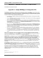
M2M Application Framework Software Design
AVIDdirector-M2M comes complete with AVIDWireless’ M2M Application Framework (M2MApp) to facilitate
rapid development and deployment of M2M and Telemetry applications. It provides far more power than the
J2ME Midlet environment since it provides most of the communication, device and system management
functions that a developer would normally have to write and test. When we use the term framework, we refer to
an object-oriented framework defined Ralph Johnson and Brian Foote3 as: "A set of classes that embodies an
abstract design for solutions to a family of related problems". M2MApp will allow developers to generate
applications enabling higher productivity and shorter development time. The framework deals with the network
infrastructure that handles the communication between M2M device and M2MXML server, management of
sensors and I/O devices on the AVIDdirector-M2M and provides an applications interface for fast and easy
development.
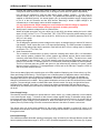
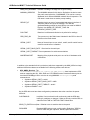
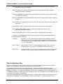
The overall view of how the AVIDdirector-M2M, M2MXML and the M2MXML portal fit together is:
AVIDirector-M2M
M2MXML
Internet
Internet
AVIDirector-M2M
M2MXML
Server &
Web Portal
M2MXML
Devices to Control and
Sensors to Monitor
AVIDdirector-M2M device performs the actual control and monitoring of remote devices and sensors. They can
be programmed to do this either by:
§
M2MXML. M2MXML provides a robust, extensible language to specify both direct remote control of the
M2M devices and also on-board intelligent behavior. This allows a M2MXML Server to automatically
configure AVIDdirector-M2M devices to the particular device or situation and perform complex tasks
without writing a custom application on the device. The M2MXML Server can be written in any language
(.NET, Java, PHP) since the sole specification and interface between the AVIDdirector-M2M device and
the Server is the M2MXML specification4.
§
Writing a custom M2Mlet. M2Mlets are small applications that handle the direct control and monitoring
of devices and performing operations either too complex for M2MXML or on-device behaviors which are
3
See http://st-www.cs.uiuc.edu/users/johnson/frameworks.html for links to other frameworks
4
See Appendix 5 and http://www.m2mxml.org for further details and specifications.
February 5, 2009
©AVIDwireless 2004-2009 All Rights Reserved
Page 12 of 55
AVIDdirector-M2M™ Technical Reference Guide
currently not implemented via the existing M2MApp. A developer needs to program in Java and will
need a basic understanding of the M2MApp APIs in order to write an M2Mlet.
M2MApp is the main program running on the device. It controls the execution of the IODevices, the
communication devices (Radios), any user written application (M2Mlet), parsing and generation of M2MXML
messages to and from the M2MXML server / portal. This is an extensible framework that can be easily adapted
to each customer’s unique device and control application without having to make changes to the framework’s
infrastructure. Since M2MApp handles all the communications, input and output control, message passing and
error control, users can develop M2Mapplications in a fraction of the time it would take them if they had to
design and implement the protocols, communications mechanisms, M2MXML parsing and device drivers.
M2MApp is written in Java and uses the Java concepts of dynamical class loading, inheritance, interfaces and
method overriding to implement its functionality.
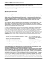
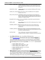
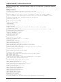
The M2MApp is designed as follows:
Key concepts and features of the M2M Application Framework are:
M2Mlet
If a custom user application is required, the developer writes a “M2Mlet”, similar to a Midlet in J2ME
or an Applet in J2SE. An M2Mlet has start() and stop() methods that must be implemented in the
user application. If the program requires background processing it must start a Thread to perform
the processing until the stop() method is called. M2Mapp loads the user written M2Mlet specified in
the M2MApp.ini5 configuration file.
5
See Appendix 6 “Sample M2MApp.ini Configuration File”
February 5, 2009
©AVIDwireless 2004-2009 All Rights Reserved
Page 13 of 55
AVIDdirector-M2M™ Technical Reference Guide
The user M2Mlet inherits from the abstract class com.avidwireless.AVIDdirector.M2Mlet and
implements the start (AVIDdirectorMain adApp) and stop(). All M2MXML messages not addressed to a
particular transducer are directed towards the M2Mlet and methods corresponding to each
M2MXML message are called depending on the M2MXML message received. The user M2Mlet can
override each of these methods if they wish to. The methods are:
§
processControlCommand(ControlCommand message). The default action is to return a
Response.UNRECOGNIZED_COMMAND_RESULT_CODE message to the portal.
§
processConfigurationQuery(ConfigurationQuery message). This will return the value of any property
in the configuration file M2MApp.ini. For example, a query of “AVIDDIRECTOR.MODEL” will
return which AVIDdirector-M2M model this is (the normal response is “M2M”). There are special
predefined Queries that may be inquired that are not M2MApp.ini values. These are:
§
§
STATUS. This returns the software version, how long the M2MApp has been running, the
SNAP and PSoC version, radio type and last log message.
processSetConfiguration(SetConfiguration message). If not overridden this will set the
specified property in the M2MApp.ini file and also invoke the method
processSetConfigurationItem (String propertyName, String oldValue, String
newValue, String seqNum). The user M2Mlet will typically implement the
processSetConfigurationItem method to respond to specific property settings and update
any operation because of the property changes.
§
processFileUpdate(FileUpdate message). The default action is to return a
Response.UNRECOGNIZED_COMMAND_RESULT_CODE message to the portal.
§
processPPPConfig(PPPConfig message). The default action is to return a
Response.UNRECOGNIZED_COMMAND_RESULT_CODE message to the portal.
§
processRebootCommand(RebootCommand message). This will send out the acknowledgement
and shutdown the M2MApp and reboot the processor once the confirmation message has been
sent to the portal.
§
processResponse(Response message). The default action is to return a
Response.UNRECOGNIZED_COMMAND_RESULT_CODE message to the portal.
§
processTimeSync(TimeSync message). This updates the devices’s real-time clock to the time
specified in the message.
Each message returns a String which is a M2MXML message to send back to the portal, which are
typically Command Response messages. If the M2Mlet needs to send a message separately to the
portal it can call app.sendMessageToPortal(String) to send the M2MXML message to the portal
by placing the message in the outgoing message queue.
Radio
M2MApp manages the radio’s and the M2MXML packets sent and received over each radio. It
allows multiple radios to be dynamically loaded via the M2MApp.ini file and switching between
which radio will be used for communications based on parameters such as least cost routing, signal
strength and geographical location.
Each radio class implements the ADRadio class that provides a standard interface to allow
M2MApp to control and work with each radio. This allows easy development of customer and
network specific radio devices. A “Radio” may be any device that M2MApp uses to communicate
with the M2MXML port, so an Ethernet port may also be a Radio. The
com.avidwireless.radio.ADRadio class specifies methods for:
§
start(AVIDdirectorMain mainApp). Called with the Radio class is loaded, it initializes
powers up the Radio, resets it, initializes the Radio communications channel, establishes
contact with the network and any other items to make the radio ready to communicate.
§
stop(). Called when the system is shutting down, it disconnects the radio from the
communications channel and powers down the radio.
§
resetRadio(). Resets the radio hardware.
February 5, 2009
©AVIDwireless 2004-2009 All Rights Reserved
Page 14 of 55
AVIDdirector-M2M™ Technical Reference Guide
§
receiveDataString(). This will return a String from the Radio, which is normally a M2MXML
string.
§
receiveDataString(int timeout). Like receiveDataString() except it will return a null if it
times out without receiving a M2MXML string from the radio.
§
receiveDataByteArray(byte[] buffer, int offset, int length). Allows receiving
binary data from the radio.
§
receiveDataByteArray(byte[] buffer, int offset, int length, int timeout).
Receives binary data from the radio but will return no characters if it times out before data is
received.
§
sendDataString (String dataStr). Sends the specified string, which is normally a
M2MXML packat, to the Radio.
§
sendDataByteArray (byte[] buffer). Sends the binary array to the radio.
§
isInNetworkContact(). Returns true if the radio is in network contact, false if it is out of
network contact.
§
getRadioNetworkAddress(). Returns the radio’s current network address as a String. This
may be the MAN number, IP address or other network specific address.
There are other methods a Radio class must implement to be supported by M2MApp.
IODevices
The com.avidwireless.AVIDdirector.iodevice.IODevice class provides the framework for all
I/O devices. It defines methods to start and stop each device and handle transducer specific
messages addressed to the IODevice. Each IODevice has several important attributes:
§
§
§
DeviceName. This is a standard name for the device. If there are multiple devices of the same
type (e.g. RFID Readers) each has the same DeviceName.
KeyName. IODevice’s are uniquely specified by their KeyName. In the M2MApp.ini file each
IODevice class (except the standard M2M_IODevices) are specified by a property
“keyname.CLASSNAME” with the fully qualified Java classname for the device specified for the
class. Each IODevice must have a unique KeyName, e.g. multiple devices of the same type will
have unique KeyNames. This allows the configuration properties to be separately specified for
each device, and the KeyName is the default M2MXML address for the device.
M2MXML_Address. Each IODevice may specify a M2MXML device different from the
KeyName. For example, when using the Simulator board TTL1 is addressed as TTL1.AIN to
distinguish this as an analog input transducer.
com.avidwireless.avidirector.iodevice.IODevice is the parent class for all I/O devices. The
configuration parameters it supports are implemented by each child IODevice if it makes sense for
the IO device. If the IODevice is a serial device it will use the serial port parameters. Each
configuration parameter is appended to the device name in the M2MApp.ini/M2MApp.ini.default
files. So GPS.CLASSNAME has a device name and M2MXML address of "GPS".
IODevice
.CLASSNAME
Specifies the Java class used to implement this device. The internal
M2M IODevices do not need this.
.LOAD
For IO Devices loaded via CLASSNAME, this needs to be set true to
load the IODevice. In M2MApp.ini this defaults to False for most IO
Devices. If not true for M2MIODEVICE then none of the internal
M2M IODevices (TTLn) will be loaded.
.ENABLE
True to enable the IO device, false to disable it operating. Mainly
used by the internal M2MIODevices
February 5, 2009
©AVIDwireless 2004-2009 All Rights Reserved
Page 15 of 55
AVIDdirector-M2M™ Technical Reference Guide
.NUM_AVG_READINGS
Number of reading to average over to get a reading
.M2MXML_ADDRESS
The M2MXML address for this device. Defaults to the device name
(the prefix name before the .CLASSNAME.) This can be a comma
separated list of different M2MXML address this will respond to. The
first name is used when we send a percept reading.
.REPORT_AT
Absolute time(s) as a set of comma delimited strings in the form of
"hhmmss" that we will report the readings. This calls the
getSensorReading method for the IO Device (not used for M2M IO
Devices. Use ABSOLUTE_REPORT_TIME and
PERIODIC_REPORT_TIME
.POLLTIME
Base time in milliseconds this device is polled at for readings.
.RDD_PWR_ON
Turns power on to the Radio board. Needed for the GPS or other IO
Devices on the Radio board.
.SERIAL_PORT
Name of the serial port to use. serial1, serial2, serial3. serial0 can be
used if the serial server is disabled
.SERIAL_PORT_BAUD_RATE
Baud rate for the serial port
.SERIAL_PORT_TIMEOUT Timeout parameter for serial communications
.MAPSERIALPORT
Mapping of the physical serial port to one of the 16 hardware serial
connections.
In addition to the standard built-in input devices (which are supported by the M2M_IODevice class)
additional IODevices classes are available for the following sensors and devices:
§
GPS_NMEA_Receiver. The
com.avidwireless.AVIDdirector.iodevice.GPS_NMEA_Receiver class implements a GPS
receiver supporting the GLL, GGA, RMC and VTG NEMA formats. Parameters that may be set
via either the M2MApp.ini file or over the air using M2MXML SetConfiguration portal
commands are:
§
KeyName.SERIAL_PORT = serial1
§
KeyName.SERIAL_PORT_BAUD_RATE = 4800
§
KeyName.SERIAL_PORT_TIMEOUT = serial1
§
KeyName.ENABLE = true
On the GPS device we have these configuration parameters above the ones from the parent
IODevice:
.CONTINUOUS
true|false. If set true then this will continuously read the GPS data
looking for variations or changes. If false we will only read the GPS on
either the POLLTIME or FASTPOLLTIME. Default false
.SEND_TO_PORTAL true|false. Defaults to true to send the data to the portal
.REQUIRED
February 5, 2009
Required NMEA strings to get a valid reading. Defaults to "GPGGA,
GPVTG" which will give is position, altitude, speed and direction
©AVIDwireless 2004-2009 All Rights Reserved
Page 16 of 55
AVIDdirector-M2M™ Technical Reference Guide
.MATCH_TIMESTAMPS
true|false. Defaults to false but if set true then the all NMEA sentences
must have the same time stamp or we won't send their data to the
portal. This ensures accurate GPS data for position, altitude, speed
and direction.
.UPDATE_RTC_TIME
true|false. Defaults to true to update the AVIDdirector RTC with the
GPS timestamp.
.UPDATE_RTC_TIME_INTERVAL How often to ensure the AVIDdirector RTC is updated?
Defaults to once a day.
.MAX_ALLOW_GPS_RTC_DIFFERENCE Maximum time between the RTC and GPS time
before we reboot the system when updating the RTC. Defaults to 30
minutes. If the time correction is greater than this then we could lose
readings or not respond correctly.
.ENHANCED_GPS true|false. If set true the M2MXML includes altitude, speed and direction.
Defaults to false
.SPEED_UNITS
Can be MPH for miles per hour, KPH for Kilometers per hour. If blank
defaults to Knots
.TRIGGER_FASTPOLL_SPEED If the speed is above this value we report readings at the
FASTPOLLTIME rate. If slows below this rate then the standard
POLLING rate.
.TRIGGER_FASTPOLL_METERS If the distance moved between GPS readings is more than
this distance in meters, we move to the FASTPOLLTIME rate. If below
then drops to standard polling rate.
.FASTPOLLTIME
§
Time in milliseconds to report when we have exceeded the
TRIGGER_FASTPOLL_SPEED or TRIGGER_FASTPOLL_METERS
Sirit_OEM400_RFIDReader. (Also - Sirit_OEM200_RFIDReader) Class
com.avidwireless.AVIDdirector.iodevice.Sirit_OEM400_RFIDReader implements the
Sirit (see http://www.sirit.com) OEM-400 RFID reader for HF (13.5 Mhz) RFID tags and
com.avidwireless.AVIDdirector.iodevice.Sirit_OEM400_RFIDReader implements the
OEM-200 UHF reader. This allows reading the Tag ID and Data blocks, either as a String or
byte array, and writing the Data blocks as a String or byte array. Parameters that may be set via
either the M2MApp.ini file or over the air using M2MXML SetConfiguration portal commands
are:
§
§
KeyName.SERIAL_PORT = serial1
§
KeyName.SERIAL_PORT_BAUD_RATE = 4800
§
KeyName.SERIAL_PORT_TIMEOUT = serial1
§
KeyName.TAGTYPE = ISO (HF) or 0,1 or 2 (UHF)
§
KeyName READ_REPEAT = 4
§
KeyName.ENABLE = true
BPI216_SerialLCD. This class is for the Scott Edwards (see http://www.seetron.com ) BPI-216
Serial LCD Module. The BPI-216 is a 2-line by 16-character LCD with a serial interface for easy
use. This allows sending messages to the display to show progress or to ask the operator to
perform settings of a device. The BPI -216 has a switch selectable baud rate that must be set to
9600 baud for communication with this class. This is implemented using the
com.avidwireless.AVIDdirector.iodevice.BPI216_SerialLCD class. Parameters that may
February 5, 2009
©AVIDwireless 2004-2009 All Rights Reserved
Page 17 of 55
AVIDdirector-M2M™ Technical Reference Guide
be set via either the M2MApp.ini file or over the air using M2MXML SetConfiguration portal
commands are:
§
§
KeyName.SERIAL_PORT = serial2
TempTrack. This device has two Analog to Digital converter inputs that are accessed by
sending an ASCII ‘G’ character to the serial port and it returns a two character strings with the
values from 0.0 to 999.9 This is best used as a sample of a user written IODriver class. This
implements the Parameters that may be set via either the M2MApp.ini file or over the air using
M2MXML SetConfiguration portal commands are:
§
KeyName.SERIAL_PORT = serial1
§
KeyName.SERIAL_PORT_BAUD_RATE = 9800
§
KeyName.SERIAL_PORT_TIMEOUT = serial1
User written I/O device driver classes subclass IODevices and must implement
start(AVIDdirectorMain adApp) and any of the IODevice methods the device needs to
implement or override. All M2MXML messages addressed to this particular transducer are directed
towards the instance of IODevice with the KeyName or M2MXMLAddress corresponding to the
M2MXML address. IODevice has a default method implementation for each M2MXML message
appropriate for transducers/sensors. The method corresponding to each M2MXML message is
called depending on the M2MXML message received. The user IODevice class can override each
of these methods if they wish to. The methods are:
§
processControlCommand(ControlCommand message). The default action is to return a
Response.UNRECOGNIZED_COMMAND_RESULT_CODE message to the portal. Any digital
transducers should implement this method.
§
processPerceptRequest(PerceptRequest message). The default action is to return a
Response.UNRECOGNIZED_COMMAND_RESULT_CODE message to the portal. Almost every
IODevice will implement this method to return the current sensor reading to the M2MXML portal
on demand.
If the sensor or transducer takes a significant amount of time to perform a reading (more than
200 ms) then it is recommended that the sensor call startPerceptRequestThread
(PerceptRequest perceptRequest) to start a background thread to perform this
PerceptRequest. This requires the IODevice to implement
processPerceptRequestThread(PerceptRequest message) method that will perform the
actual reading.
§
processConfigurationQuery(ConfigurationQuery message). This will return the value of
any property in the configuration file M2MApp.ini for this transducer. For example, a query of
“SIRIT_OEM200_RFID_READER.TAGTYPE” will return which RFID tag type (ISO, Tag-IT,
Epic class 0, 1 or 2) this sensor is set to receive. By default, IODevice’s implementation will
prefix the property name with the keyname and return that value (if set) or
Response.BAD_ARGUEMENT_RESULT_CODE if this is not set. Most IODevice implementation do
not need to implement this method.
§
processSetConfiguration(SetConfiguration message). If not overridden this will prefix
the property with the IODevice’s keyname, set the specified property in the M2MApp.ini file and
invoke the method processSetConfigurationItem (String propertyName, String
oldValue, String newValue, String seqNum). The user IODevice will typically implement
the processSetConfigurationItem method to respond to specific property settings and
update any operation because of the property changes.
M2M_IODevice
The standard AVIDdirector-M2M devices are implemented by the
com.avidwireless.AVIDdirector.iodevice.M2M_IODevices class. This handles all the portal
messages to the devices, configuration settings and implements the on-device behaviors.
February 5, 2009
©AVIDwireless 2004-2009 All Rights Reserved
Page 18 of 55
AVIDdirector-M2M™ Technical Reference Guide
Through M2MXML the user can program on device behavior such as trigger limits, sensor deadzones, polling modes, scheduled execution, and I/O control. This means that for many M2M
applications no embedded device programming is required and all device behavior and operation
can be specified by M2MXML commands sent over-the-air (OTA) to the device.
M2M_IODevice implements a nominal 200ms polling of the input devices and each AVIDdirectorM2M device can be added to the polling loop by setting the POLLING attribute in the M2MApp.ini
configuration file or by a SetConfiguration command to the M2M_IODevice with the property
POLLING set to true. When polling, each device is set to input mode and any transitions are sent
as PerceptReadings to the M2MXML portal.
For the internal M2MIO Devices (the 22 TTL devices) these parameters can be used for each of the
TTLn ports:
.IOTYPE=type, where type is AIN, DIN, AOUT or DOUT
.POLLING=true
.READING_PROCESSOR_CLASSNAME=classname of IODeviceReadingProcessor instance to
use. An IODeviceReadingProcessor has methods called for initialize, startReading,
processControlCommand, processDigitalPerceptRequest, processAnalogPerceptRequest,
processSetDigitalOutput, processSetAnalogOutput and endReading
.ABSOLUTE_REPORT_TIME=nnn Set an absolute GMT time to report the current reading value.
Time is in GMT seconds for each day.
.PERIODIC_REPORT_TIME=nnn Set an periodic time to report the current reading value. Time is
in milliseconds
.REPORT_MINIMUM_INTERVAL_TIME=nnn Set period of time, in milliseconds, to wait before we
report a change in a value
.DIGITAL_TRIGGER_HIGH=true|false Report if the input goes from a low to a high. For digital
inputs.
.DIGITAL_TRIGGER_LOW=true|false Report if the input goes from a high to a low . For digital
inputs.
.INVERT=true|false If set true this will invert the reported value. For digital inputs.
.PULLUP_INPUT=true|false Set the port to have an active pull-up using the PSoC. For digital
inputs.
.PULLDOWN_INPUT=true|false Set the port to have an active pull down using the PSoC. For digital
inputs.
.PULSEHIGH_TIME=nnn Set the time to pulse the output high. Time in milliseconds. For digital
outputs.
.PULSELOW_TIME=nnn Set the time to pulse the output low. Time in milliseconds. For digital
outputs.
.ANALOG_OFFSET=dd.dd Sets offset applied to the analog input or output. For Analog I/O.
.ANALOG_FACTOR=dd.dd Sets factor (multiplier) applied to the analog input or output. For Analog
I/O.
February 5, 2009
©AVIDwireless 2004-2009 All Rights Reserved
Page 19 of 55
AVIDdirector-M2M™ Technical Reference Guide
.ANALOG_ABSOLUTE_HIGH=dd.dd Sets absolute high value for the analog input to report a
reading to the portal. For Analog In.
.ANALOG_ABSOLUTE_LOW=dd.dd Sets absolute low value for the analog input to report a
reading to the portal. For Analog In.
.ANALOG_DEADBAND_HIGH=dd.dd Sets delta high value for the analog input to report a reading
to the portal. For Analog In.
.ANALOG_DEADBAND_LOW=dd.dd Sets delta low value for the analog input to report a reading to
the portal
.AUX_DEVICE=TTLn digital device to turn on or off or set value before and/or after the reading has
taken place.
.AUX_DEVICE_START_VALUE=n Value to set the device to before the reading begins
.AUX_DEVICE_DELAYTIME=nnn Time to delay after setting the Aux device to the
startDeviceValue before reading
.AUX_DEVICE_END_VALUE=n Value to set the device to after the reading is complete
In addition for the M2MIODEVICE which is the overall class for all the internal M2M IODevices,
these parameters can be used:
.LOADALL
By default, only TTLn devices that are specified in the M2MApp.ini file are
loaded (TTL1 to TTL6). You cannot send commands or percept requests to
TTL devices unless they are loaded. Setting LOADALL to true will load all the
TTL1 to TTL22 devices.
.USE_TTL2023
If set true then TTL20 to TTL23 are available for control. This is set false if
these are used for a serial port. The M2MApp.ini.default sets this true.
.USE_EXT14
If set true then EXT1 to EXT4 (lines on the Radio board) can be used for M2M
IODevices. This is typically set false since these lines are used for Radio2
The Configuration files
Under the root directory for your device will notice various system configuration files, these files are used to
configure your AVIDdirector handle various parameters set on AVIDdirector.
The M2MApp.ini.default file is the main configuration file. It contains all standard AVIDdirector options.
Developers should not modify this file but should instead utilize the other file to override parameters set in the
M2MApp.ini.default file. For example the M2MApp.ini file is used to set parameters and override values set in
the M2MApp.ini.default file. Below you will see examples of each of the configuration files and examples of how
to use these files to handle your application.
When you start developing your own m2mapp, there is the -c filename option to specify the configuration file to
use (defaults to M2Mapp.ini, that uses M2Mapp.ini.default), and m2mapp - C config=nnnn allows manual
February 5, 2009
©AVIDwireless 2004-2009 All Rights Reserved
Page 20 of 55
AVIDdirector-M2M™ Technical Reference Guide
override of a config file entry. There can be multiple -C config=nnn -C config2=mmm -C config3=xxx entered on
the same line.
M2MApp.ini.default
# Config File: M2MApp.ini Updated: 10/22/2008 9:59:12PM
# M2MApp M2MApp Ver:2.0.0(Build:2008102101)[57.10.19.7.10.50.15.39.12]
#
# Master M2MApp.ini file. This contains all IODEvices, Radios and standard M2Mlets.
# Most of them have the .LOAD=false to prevent them from loading. The M2MApp.ini file
#
# Specify the device type, 100 (Rev A or B) or 200 (Rev C)
AVIDIRECTOR.MODEL=200
#
##### System Settings #####
#
SYSTEM.APP_NAME=M2MApp
SYSTEM.DEBUG=0
SYSTEM.LOGGING=0
SYSTEM.OPTIONS=0
# AVIDdirector Unique number (if not set uses device's serial # or phone#)
# SYSTEM.DEVICE_UUID=
# Maximum time without communications with the portal before we auto-reboot - 1 day
# SYSTEM.MAX_NOCOMM_TIME=86400000
# Level below which we do a GC
SYSTEM.GC_WATERMARK = 100000
SYSTEM.GC_RUN_INTERVAL=60
# Watchdog timer reset
SYSTEM.WATCHDOG=true
#
##### M2MXML Settings #####
# Version of M2MXML. Use 1.1, 1.0 or Beta
M2MXML.VERSION=1.1
# M2MXML Server Settings
M2MXML.SERVER_IP_ADDRESS=aviddashboard.com
M2MXML.SERVER_PORT=8088
M2MXML.SERVER_HTTP_SEND_PAGE=/AVIDdirector/Host?msg=
M2MXML.SERVER_HTTP_POLL_PAGE=/AVIDdirector/Host?uuid=
# M2MXML.SERVER_POLL_TIME=180000
# UDP Port received the Messages or Shoulder taps from the server
# M2MXML.SERVER_UDP_PORT=4321
#
##### M2MLET APPLICATION CLASSES #####
#
# Jumpstart Demo Board M2MLet
DEMO_M2MLET.CLASSNAME=com.avidwireless.avidirector.Demo_M2Mlet
DEMO_M2MLET.LOAD=false
DEMO_M2MLET.DEMO_ENABLED=true
# Update specifies when to send data automatically to the Server
# DEMO_M2MLET.DEMO_UPDATE_INTERVAL=60000
#
# Modbus Reader application class to load
MODBUS_M2MLET.CLASSNAME=Modbus_M2Mlet
MODBUS_M2MLET.LOAD=false
# How often we will be reporting in 5 minutes
MODBUS_M2MLET.UPDATE_INTERVAL=120000
# Serial Port Settings
MODBUS_M2MLET.SERIAL_PORT=serial1
MODBUS.SERIAL_PORT_BAUDRATE=9600
MODBUS.SERIAL_PORT_DATABITS=8
MODBUS.SERIAL_PORT_PARITY=None
MODBUS.MODBUS_ASCII=false
MODBUS.MODBUS_RETRY_COUNT=2
MODBUS.MODBUS_POLL_DELAY=1
# MODBUS device address
MODBUS_M2MLET.MODBUS_DEVICE=1
# Starting address for floating analog 32 bit registers we are reading
February 5, 2009
©AVIDwireless 2004-2009 All Rights Reserved
Page 21 of 55
AVIDdirector-M2M™ Technical Reference Guide
MODBUS_M2MLET.MODBUS_START_ADDRESS=800101
# Names of the Floating values we are reading
MODBUS_M2MLET.MODBUS_NAMES=MOD1.AI1,MOD1.AI2
MODBUS_M2MLET.MODBUS_FLOATING=true
# Starting address for digital discrete registers we are reading
MODBUS_M2MLET.MODBUS_START_ADDRESS1=100001
# Names of the Digital values we are reading
MODBUS_M2MLET.MODBUS_NAMES1=MOD1.DI48,MOD1.DI87
# Starting address for floating analog 32 bit registers we are reading
# MODBUS_M2MLET.MODBUS_START_ADDRESS2=800001
# Names of the Short values we are reading
# MODBUS_M2MLET.MODBUS_NAMES2=MOD1.AO25,MOD1.AO51
#
#
##### M2M_IODEVICES (On board Devices) #####
#
# Possible arguments for the TTL devices are
# TTLn.M2MXML_ADDRESS=TTLn.subdevice
# TTLn.IOTYPE=type, where type is AIN, DIN, AOUT or DOUT
# TTLn.POLLING=true
# TTLn.READING_PROCESSOR_CLASSNAME=classname of IODeviceReadingProcessor instance
# TTLn.NUM_AVG_READINGS=n Number of readings to be used for getting an average reading
# TTLn.ABSOLUTE_REPORT_TIME=nnn Set an absolute GMT time to report the current reading
value. Time is in GMT seconds for each day.
# TTLn.PERIODIC_REPORT_TIME=nnn Set an periodic time to report the current reading value.
Time is in milliseconds
# TTLn.REPORT_MINIMUM_INTERVAL_TIME=nnn Set period of time, in milliseconds, to wait before
we report a change in a value
# TTLn.DIGITAL_TRIGGER_HIGH=true|false Report if the input goes from a low to a high
# TTLn.DIGITAL_TRIGGER_LOW=true|false Report if the input goes from a high to a low
# TTLn.INVERT=true|false If set true this will invert the reported value
# TTLn.PULLUP_INPUT=true|false Set the port to have an active pullup using the PSoC
# TTLn.PULLDOWN_INPUT=true|false Set the port to have an active pulldown using the PSoC
# TTLn.DURATION=nnn Set the time interval to set the output. Time in milliseconds
# TTLn.PULSEHIGH_TIME=nnn Set the time to pulse the output high. Time in milliseconds.
# TTLn.PULSELOW_TIME=nnn Set the time to pulse the output low. Time in milliseconds.
# TTLn.ANALOG_OFFSET=dd.dd Sets offset applied to the analog input or output.
# TTLn.ANALOG_FACTOR=dd.dd Sets factor (multiplier) applied to the analog input or output
# TTLn.ANALOG_ABSOLUTE_HIGH=dd.dd Sets absolute high value for the analog input to report a
reading to the portal.
# TTLn.ANALOG_ABSOLUTE_LOW=dd.dd Sets absolute low value for the analog input to report a
reading to the portal
# TTLn.ANALOG_DEADBAND_HIGH=dd.dd Sets delta high value for the analog input to report a
reading to the portal
# TTLn.ANALOG_DEADBAND_LOW=dd.dd Sets delta low value for the analog input to report a
reading to the portal
#
# M2M On device address which match the Jumpstart board
TTL1.M2MXML_ADDRESS=TTL1.AIN
TTL1.IOTYPE=AIN
TTL1.ANALOG_DEADBAND_HIGH=60.0
TTL1.ANALOG_DEADBAND_LOW=60
TTL2.IOTYPE=AOUT
TTL3.IOTYPE=DOUT
TTL4.IOTYPE=DOUT
TTL5.M2MXML_ADDRESS=TTL5.DIN
TTL5.IOTYPE=DIN
TTL6.M2MXML_ADDRESS=TTL6.DIN
TTL6.IOTYPE=DIN
#
# M2M_IO Device common settings
# M2MIODEVICE.POLLTIME=20000
# Enable the Serial2 (TTL20-23) and Ext1-4 lines (RadioB) for direct control
M2MIODEVICE.USE_TTL2023=true
# Load the M2M_IODEVICES or Load ALL the M2M_IODEVICES (ones not listed here)
M2MIODEVICE.LOAD=true
February 5, 2009
©AVIDwireless 2004-2009 All Rights Reserved
Page 22 of 55
AVIDdirector-M2M™ Technical Reference Guide
M2MIODEVICE.LOADALL=false
#
##### IODEVICES #####
#
# NMEA GPS Receiver to load
GPS.CLASSNAME=com.avidwireless.avidirector.iodevice.GPS_NMEA_Receiver
GPS.LOAD=false
GPS.SERIAL_PORT=serial1
GPS.MAPSERIALPORT=GPS
GPS.RDD_PWR_ON=true
GPS.SERIAL_PORT_BAUD_RATE=4800
GPS.SERIAL_PORT_TIMEOUT=5000
GPS.SONY=false
GPS.USGLOBALSAT=true
GPS.ENHANCED_GPS=true
GPS.SPEED_UNITS=MPH
# Send GPS readings once every 8 hours unless we are moving
GPS.POLLTIME=28800000
GPS.CONTINUOUS=false
# GPS.GPS_INIT_STRING=$PSRF103,00,00,10,01~$PSRF103,04,00,10,01~$PSRF103,05,00,10,01
# GPS.GPS_START_READING=$PFST,START,0
# GPS.FASTPOLL_TIME=nnn Time in milliseconds to report when FASTPOLL criteria met
# GPS.TRIGGER_FASTPOLL_SPEED=mm Speed in MPH (or KPH) that trigger the FASTPOLL update rate
# GPS.TRIGGER_FASTPOLL_METERS=mmm Distance in meters moved that triggers a FASTPOLL update
Rate
GPS.FASTPOLL_TIME=60000
GPS.TRIGGER_FASTPOLL_SPEED=10
GPS.TRIGGER_FASTPOLL_METERS=1000
GPS.REQUIRED=GPRMC,GPGGA
#
# BPI216 SerialLCD to load
LCD.CLASSNAME=com.avidwireless.avidirector.iodevice.BPI216_SerialLCD
LCD.LOAD=false
LCD.ADDRESS=LCD
LCD.SERIAL_PORT=serial1
#
# SIRIT UHF INFINITY 210/OEM200 RFID Reader class
SIRIT_OEM200_READER.CLASSNAME=com.avidwireless.avidirector.iodevice.SIRIT_OEM200_READER_RFI
DReader
SIRIT_OEM200_READER.LOAD=false
SIRIT_OEM200_READER.M2MXML_ADDRESS=RFIDReader
SIRIT_OEM200_READER.SERIAL_PORT=serial1
SIRIT_OEM200_READER.TAGTYPE=0
SIRIT_OEM200_READER.READ_REPEAT=1
SIRIT_OEM200_READER.POLLTIME=200
SIRIT_OEM200_READER.ENABLE=true
#
# SIRIT OEM-400 HF RFID Reader
SIRIT_OEM400_READER.CLASSNAME=com.avidwireless.avidirector.iodevice.Sirit_OEM400_RFIDReader
SIRIT_OEM400_READER.LOAD=false
SIRIT_OEM400_READER.M2MXML_ADDRESS=RFIDHFReader
SIRIT_OEM400_READER.SERIAL_PORT=serial2
SIRIT_OEM400_READER.MAPSERIALPORT=RadioB
SIRIT_OEM400_READER.RDD_PWR_ON=true
SIRIT_OEM400_READER.TAGTYPE=ISO
SIRIT_OEM400_READER.POLLTIME=200
SIRIT_OEM400_READER.ENABLE=true
#
# AVIDSmartSensors
SMARTSEN.CLASSNAME=com.avidwireless.avidirector.iodevice.SmartSensors
SMARTSEN.LOAD=false
SMARTSEN.CONTINUOUS=TRUE
SMARTSEN.SEND_ALL_READINGS=TRUE
SMARTSEN.DISPLAY_ALL_READINGS=TRUE
SMARTSEN.SERIAL_PORT=serial2
SMARTSEN.MAPSERIALPORT=RadioB
SMARTSEN.RDD_PWR_ON=true
February 5, 2009
©AVIDwireless 2004-2009 All Rights Reserved
Page 23 of 55
AVIDdirector-M2M™ Technical Reference Guide
SMARTSEN.SERIAL_PORT_BAUD_RATE=19200
SMARTSEN.SERIAL_PORT_TIMEOUT=10000
# Individual AVIDSmartSensors are identified with a name and the _SNUM trailer specifying
the address.
# Parameters for the device names are .SEND, .MIN, .MAX, .THRESHOLD, .THRESHOLD2, .DELTA,
# .DELTA2, .FACTOR, .FACTOR2, .OFFSET, .OFFSET2, .IODEVICE_READING_PROCESSOR_CLASS.
# Next is an example for a magnetic sensor 'DOOR' at E9DE0A00
# SMARTSEN.DOOR_SNUM=E9DE0A00
# DOOR.SEND=TRUE
#
# STATUS Class to provide Device Status
STATUS.CLASSNAME=com.avidwireless.avidirector.iodevice.Status
STATUS.LOAD=true
STATUS.MESSAGE_AT_STARTUP=yes
#
# SHOULDERTAP Class to handle Shoulder Tap requests
SHOULDERTAP.CLASSNAME=com.avidwireless.avidirector.iodevice.ShoulderTap
SHOULDERTAP.LOAD=false
#
#
######### RADIOS ##########
#
# To load a Radio, change the nnnn.LOAD=false to true to load the Radio class
#
# MultiTech GPRS Radio
MT_GPRS.CLASSNAME=com.avidwireless.radio.GPRSMultiTechWavecom
MT_GPRS.LOAD=false
MT_GPRS.MODEM_MODEL=GPRS
# MT_GPRS.PHONENUM=
MT_GPRS.SERIAL_PORT=serial3
MT_GPRS.SERIAL_PORT_BAUDRATE=57600
MT_GPRS.SERIAL_PORT_TIMEOUT=3000
MT_GPRS.CONNECTION_TYPE=TCPIP
MT_GPRS.KEEP_CONNECTION_UP=false
# MT_GPRS.PPP_DNS_PRIMARY=205.166.226.38
# GPRS Specific information
MT_GPRS.CARRIER=Crossbridge
MT_GPRS.GPRS_APN=
MT_GPRS.SMSC=
MT_GPRS.PPP_USERNAME=
MT_GPRS.PPP_PASSWORD=
MT_GPRS.PPP_AUTHENTICATION=PAP
MT_GPRS.PPP_HANGTIME=10000
# M2MXML Portal Information
MT_GPRS.SERVER_IP_ADDRESS=aviddashboard.com
MT_GPRS.SERVER_PORT=8088
MT_GPRS.SERVER_HTTP_M2MXML_SEND_PAGE=/AVIDdirector/Host?msg=
MT_GPRS.SERVER_HTTP_M2MXML_POLL_PAGE=/AVIDdirector/Host?uuid=
MT_GPRS.SERVER_M2MXML_POLL_TIME=600000
# MT_GPRS.SERVER_M2MXML_UDP_PORT=4321
MT_GPRS.SERVER_SMS_NUMBER=76001
MT_GPRS.MAX_RETRY_COUNT=3
MT_GPRS.MAX_QUEUE_SIZE=100
MT_GPRS.MAX_FATAL_ERRORS=10
MT_GPRS.RESTORE_NETWORK_DNS=true
MT_GPRS.TEST_NETWORK_CONNECTIVITY=0
# Information for Dynamic DNS lookup
MT_GPRS.DYNDNS_AUTOUPDATE=N
MT_GPRS.DYNDNS_HOSTNAME=demo1.avidm2m.com
MT_GPRS.DYNDNS_USERNAME=
MT_GPRS.DYNDNS_PASSWORD=
MT_GPRS.DYNDNS_DNS_TYPE=custom
#
# MultiTech CDMA Radio
MT_CDMA.CLASSNAME=com.avidwireless.radio.CDMAMultiTechWavecom
MT_CDMA.LOAD=false
MT_CDMA.MODEM_MODEL=CDMA
February 5, 2009
©AVIDwireless 2004-2009 All Rights Reserved
Page 24 of 55
AVIDdirector-M2M™ Technical Reference Guide
MT_CDMA.SERIAL_PORT=serial3
MT_CDMA.SERIAL_PORT_BAUDRATE=57600
MT_CDMA.SERIAL_PORT_TIMEOUT=3000
MT_CDMA.CONNECTION_TYPE=TCPIP
MT_CDMA.KEEP_CONNECTION_UP=false
#MT_CDMA.PPP_DNS_PRIMARY=205.166.226.38
# CDMA Specific Information
MT_CDMA.CARRIER=
MT_CDMA.PPP_USERNAME=
MT_CDMA.PPP_PASSWORD=
MT_CDMA.PPP_AUTHENTICATION=PAP
MT_CDMA.PPP_HANGTIME=10000
# M2MXML Portal Information
MT_CDMA.SERVER_IP_ADDRESS=aviddashboard.com
MT_CDMA.SERVER_PORT=8088
MT_CDMA.SERVER_HTTP_M2MXML_SEND_PAGE=/AVIDdirector/Host?msg=
MT_CDMA.SERVER_HTTP_M2MXML_POLL_PAGE=/AVIDdirector/Host?uuid=
MT_CDMA.SERVER_M2MXML_POLL_TIME=600000
# MT_CDMA.SERVER_M2MXML_UDP_PORT=4321
MT_CDMA.MAX_RETRY_COUNT=3
MT_CDMA.MAX_QUEUE_SIZE=100
MT_CDMA.MAX_FATAL_ERRORS=10
MT_CDMA.RESTORE_NETWORK_DNS=true
MT_CDMA.TEST_NETWORK_CONNECTIVITY=0
# Information for Dynamic DNS lookup
MT_CDMA.DYNDNS_AUTOUPDATE=N
MT_CDMA.DYNDNS_HOSTNAME=demo1.avidm2m.com
MT_CDMA.DYNDNS_USERNAME=
MT_CDMA.DYNDNS_PASSWORD=
MT_CDMA.DYNDNS_DNS_TYPE=custom
#
# Motorola IO270 Radio
IO270.CLASSNAME=com.avidwireless.radio.IO270
IO270.LOAD=false
IO270.MODEM_MODEL=CDMA
IO270.SERIAL_PORT=serial3
IO270.SERIAL_PORT_BAUDRATE=57600
IO270.SERIAL_PORT_TIMEOUT=3000
IO270.PPP_USERNAME=
IO270.PPP_PASSWORD=
IO270.PPP_AUTHENTICATION=PAP
IO270.PPP_HANGTIME=10000
IO270.CONNECTION_TYPE=TCPIP
IO270.KEEP_CONNECTION_UP=false
#IO270.PPP_DNS_PRIMARY=205.166.226.38
IO270.MAX_RETRY_COUNT=3
IO270.MAX_QUEUE_SIZE=100
IO270.MAX_FATAL_ERRORS=10
# M2MXML Portal Information
IO270.SERVER_IP_ADDRESS=aviddashboard.com
IO270.SERVER_PORT=8088
IO270.SERVER_HTTP_M2MXML_SEND_PAGE=/AVIDdirector/Host?msg=
IO270.SERVER_HTTP_M2MXML_POLL_PAGE=/AVIDdirector/Host?uuid=
IO270.SERVER_M2MXML_POLL_TIME=600000
# UDP Port received the Shoulder taps from the server
# IO270.SERVER_M2MXML_UDP_PORT=4321
IO270.RESTORE_NETWORK_DNS=true
IO270.TEST_NETWORK_CONNECTIVITY=0
# Information for Dynamic DNS lookup
IO270.DYNDNS_AUTOUPDATE=N
IO270.DYNDNS_HOSTNAME=demo1.avidm2m.com
IO270.DYNDNS_USERNAME=
IO270.DYNDNS_PASSWORD=
IO270.DYNDNS_DNS_TYPE=custom
#
# Boomer 3 Mobitex Radio
BOOMER3.CLASSNAME=com.avidwireless.radio.Boomer3
February 5, 2009
©AVIDwireless 2004-2009 All Rights Reserved
Page 25 of 55
AVIDdirector-M2M™ Technical Reference Guide
BOOMER3.LOAD=false
BOOMER3.SERIAL_PORT=serial3
BOOMER3.SERIAL_PORT_BAUDRATE=9600
# Maximum time to send a message
BOOMER3.MAX_RETRY_COUNT=3
BOOMER3.MAX_QUEUE_SIZE=100
BOOMER3.MAX_FATAL_ERRORS=10
# Mobitex Specific network information
BOOMER3.MOBITEX_GATEWAY_ADDRESS=103087
BOOMER3.MOBITEX_GATEWAY_HPID=137
BOOMER3.ENCRYPT_MPAK = false
#
# Lantronix XPORT PPP Ethernet adapter
XPORT.CLASSNAME=com.avidwireless.radio.XPort
XPORT.LOAD=false
XPORT.SERIAL_PORT=serial3
XPORT.MAPSERIALPORT=XPORT
XPORT.RDD_PWR_ON=true
XPORT.SERIAL_PORT_BAUDRATE=57600
XPORT.SERIAL_PORT_TIMEOUT=3000
XPORT.PPP_HANGTIME=10000
XPORT.CONNECTION_TYPE=TCPIP
# XPORT.PPP_DNS_PRIMARY=205.166.226.38
XPORT.MAX_RETRY_COUNT=3
XPORT.MAX_QUEUE_SIZE=100
XPORT.MAX_FATAL_ERRORS=10
# M2MXML Portal Information
XPORT.SERVER_IP_ADDRESS=aviddashboard.com
XPORT.SERVER_PORT=8088
XPORT.SERVER_HTTP_M2MXML_SEND_PAGE=/AVIDdirector/Host?msg=
XPORT.SERVER_HTTP_M2MXML_POLL_PAGE=/AVIDdirector/Host?uuid=
XPORT.SERVER_M2MXML_POLL_TIME=60000
# UDP Port received the Shouldertaps from the server
XPORT.SERVER_M2MXML_UDP_PORT=4321
XPORT.RESTORE_NETWORK_DNS=true
XPORT.TEST_NETWORK_CONNECTIVITY=0
# Information for Dynamic DNS lookup
XPORT.DYNDNS_AUTOUPDATE=N
XPORT.DYNDNS_HOSTNAME=demo1.avidm2m.com
XPORT.DYNDNS_USERNAME=
XPORT.DYNDNS_PASSWORD=
XPORT.DYNDNS_DNS_TYPE=custom
#
# Lantronix WIPORT PPP Ethernet adapter
WIPORT.CLASSNAME=com.avidwireless.radio.XPort
WIPORT.LOAD=false
WIPORT.SERIAL_PORT=serial3
WIPORT.MAPSERIALPORT=RADIOB
WIPORT.RDD_PWR_ON=true
WIPORT.SERIAL_PORT_BAUDRATE=57600
WIPORT.SERIAL_PORT_TIMEOUT=3000
WIPORT.PPP_HANGTIME=10000
WIPORT.CONNECTION_TYPE=TCPIP
# WIPORT.PPP_DNS_PRIMARY=205.166.226.38
WIPORT.MAX_RETRY_COUNT=3
WIPORT.MAX_QUEUE_SIZE=100
WIPORT.MAX_FATAL_ERRORS=10
# M2MXML Portal Information
WIPORT.SERVER_IP_ADDRESS=aviddashboard.com
WIPORT.SERVER_PORT=8088
WIPORT.SERVER_HTTP_M2MXML_SEND_PAGE=/AVIDdirector/Host?msg=
WIPORT.SERVER_HTTP_M2MXML_POLL_PAGE=/AVIDdirector/Host?uuid=
WIPORT.SERVER_M2MXML_POLL_TIME=60000
# UDP Port received the Shoulder taps from the server
WIPORT.SERVER_M2MXML_UDP_PORT=4321
WIPORT.RESTORE_NETWORK_DNS=true
WIPORT.TEST_NETWORK_CONNECTIVITY=0
February 5, 2009
©AVIDwireless 2004-2009 All Rights Reserved
Page 26 of 55
AVIDdirector-M2M™ Technical Reference Guide
# Information for Dynamic DNS lookup
WIPORT.DYNDNS_AUTOUPDATE=N
WIPORT.DYNDNS_HOSTNAME=demo1.avidm2m.com
WIPORT.DYNDNS_USERNAME=
WIPORT.DYNDNS_PASSWORD=
WIPORT.DYNDNS_DNS_TYPE=custom
#
# Local Ethernet adapter
ETHERNET.CLASSNAME=com.avidwireless.radio.Ethernet
ETHERNET.LOAD=false
ETHERNET.MAX_RETRY_COUNT=3
ETHERNET.MAX_QUEUE_SIZE=100
ETHERNET.MAX_FATAL_ERRORS=10
# M2MXML Portal Information
ETHERNET.SERVER_IP_ADDRESS=aviddashboard.com
ETHERNET.SERVER_PORT=8088
ETHERNET.SERVER_HTTP_M2MXML_SEND_PAGE=/AVIDdirector/Host?msg=
ETHERNET.SERVER_HTTP_M2MXML_POLL_PAGE=/AVIDdirector/Host?uuid=
ETHERNET.SERVER_M2MXML_POLL_TIME=60000
# UDP Port received the Shoulder taps from the server
ETHERNET.SERVER_M2MXML_UDP_PORT=4321
ETHERNET.RESTORE_NETWORK_DNS=true
ETHERNET.TEST_NETWORK_CONNECTIVITY=0
# Information for Dynamic DNS lookup
ETHERNET.DYNDNS_AUTOUPDATE=N
ETHERNET.DYNDNS_HOSTNAME=demo1.avidm2m.com
ETHERNET.DYNDNS_USERNAME=
ETHERNET.DYNDNS_PASSWORD=
ETHERNET.DYNDNS_DNS_TYPE=custom
#
# ATMODEM PPP Ethernet adapter
ATMODEM.CLASSNAME=com.avidwireless.radio.ATModem
ATMODEM.LOAD=false
ATMODEM.SERIAL_PORT=serial3
ATMODEM.MAPSERIALPORT=RS232
ATMODEM.SERIAL_PORT_BAUDRATE=19200
ATMODEM.SERIAL_PORT_TIMEOUT=3000
ATMODEM.PPP_DIALNUMBER=2142420020
ATMODEM.PPP_DIALTIME=60000
ATMODEM.PPP_CONNECTTIME=30000
ATMODEM.PPP_USERNAME=
ATMODEM.PPP_PASSWORD=
ATMODEM.PPP_AUTHENTICATION=PAP
ATMODEM.PPP_HANGTIME=30000
ATMODEM.DNS_TIMEOUT=15000
ATMODEM.SOCKET_TIMEOUT=30000
ATMODEM.CONNECTION_TYPE=TCPIP
# ATMODEM.PPP_DNS_PRIMARY=205.166.226.38
ATMODEM.MAX_RETRY_COUNT=3
ATMODEM.MAX_QUEUE_SIZE=100
ATMODEM.MAX_FATAL_ERRORS=10
# M2MXML Portal Information
ATMODEM.SERVER_IP_ADDRESS=aviddashboard.com
ATMODEM.SERVER_PORT=8088
ATMODEM.SERVER_HTTP_M2MXML_SEND_PAGE=/AVIDdirector/Host?msg=
ATMODEM.SERVER_HTTP_M2MXML_POLL_PAGE=/AVIDdirector/Host?uuid=
ATMODEM.SERVER_M2MXML_POLL_TIME=60000
# UDP Port received the Shoulder taps from the server
ATMODEM.SERVER_M2MXML_UDP_PORT=4321
ATMODEM.RESTORE_NETWORK_DNS=true
ATMODEM.TEST_NETWORK_CONNECTIVITY=0
# Information for Dynamic DNS lookup
ATMODEM.DYNDNS_AUTOUPDATE=N
ATMODEM.DYNDNS_HOSTNAME=demo1.avidm2m.com
ATMODEM.DYNDNS_USERNAME=
ATMODEM.DYNDNS_PASSWORD=
ATMODEM.DYNDNS_DNS_TYPE=custom
February 5, 2009
©AVIDwireless 2004-2009 All Rights Reserved
Page 27 of 55
AVIDdirector-M2M™ Technical Reference Guide
M2Mapp.ini
This file is used to over-ride the parameters set in the M2Mapp.ini.default
# Config File: M2MApp.ini Updated: 10/22/2008 9:59:12PM
# M2MApp M2MApp Ver:2.0.0(Build:2008102101)[57.10.19.7.10.50.15.39.12]
#
# User specific loading of files
SYSTEM.DEVICE_UUID=
SYSTEM.DEBUG=1
ß- Use this to set a different debug level
DEMO_M2MLET.LOAD=true
M2MIODEVICE.LOADALL=true
# M2MIODEVICE.POLLTIME=20000
#
GPS.LOAD=false
ß- You would set this = true to turn on GPS
GPS.POLLTIME=28800000
GPS.FASTPOLL_TIME=60000
GPS.TRIGGER_FASTPOLL_SPEED=10
GPS.TRIGGER_FASTPOLL_METERS=1000
#
SMARTSEN.LOAD=false
ß- You would set this = true if you want to connect to
AVIDSmartSensors
#
MT_GPRS.LOAD=true
MT_GPRS.CARRIER=Crossbridge
ß- Specifies Crossbridge as our wireless carrier
MT_GPRS.SERVER_M2MXML_UDP_PORT=4321
ish.ini
This file is used to set user environment parameters such as Class Paths and Alias
# Set the Java classpath of the jar files to load
# /root/app.jar is an example of placing user specific jar files in the Classpath
# It is recommended to add jar files to the CLASSPATH and NOT in the command line with the
-classpath option
setenv CLASSPATH $CLASSPATH:/root/app.jar
# set any user aliases here
alias myapp java -w com.user.myapp
startup.ini
This is where you would put user application specific processes etc that need to happen at startup time. This is
the first file that is executed on startup. In the example below you could start up the XPORT Ethernet session at
start up by un-commenting the pppclient line.
When you start the m2mapp, there is the -c filename option to specify the configuration file to use (defaults to
M2Mapp.ini, that uses M2Mapp.ini.default), and m2mapp - C config=nnnn allows manual override of a config file
entry. There can be multiple -C config=nnn -C config2=mmm -C config3=xxx entered on the same line.
# User applications started here
#echo "Starting XPORT Ethernet"
#pppclient -s serial1 -m xport -t -f -o -l
echo "Starting AVIDirector-M2M Application Framework (M2MApp) in the background."
m2mapp -c M2MApp.ini
February 5, 2009
©AVIDwireless 2004-2009 All Rights Reserved
Page 28 of 55
AVIDdirector-M2M™ Technical Reference Guide
Appendix 1 – AVIDdirector Model 100 (see Appendix 9 for Model
200) Pin and I/O Definitions
External Connector Pin Definitions
AVIDdirector-M2M model 100 board has a Phoenix 5.08mm model1757349 for the 12 position GPIO and 1757242
for the 2 position power connector.
Pin
SensorLogic
Address
V Range
Features
PSoC Port (Pin)
Digital/Analog Connector
1
2
3
4
5
6
7
8
9
10
11
TTL1
TTL2
TTL3
TTL4
TTL5
TTL6
5V TTL
5V TTL
5V TTL
5V TTL
5V TTL
5V TTL
Ground
0 to Vsup or Vrail
0 to Vsup or Vrail
0 to Vsup or Vrail
0 to Vsup or Vrail
Dig I/O; Analog In/Out
Dig I/O; Analog In/Out
Dig I/O; Analog In
Dig I/O; Analog In
Dig I/O; Analog In (12 bit)
Dig I/O; Analog In (12 bit)
High Volt & Cur; Dig I/O; Analog In / 4
High Volt & Cur; Dig I/O; Analog In / 4
High Volt & Cur; Dig I/O
High Volt & Cur; Dig I/O
J1 in sets Vsup OUT to either 5 or 12
Vrail IN or Vsup OUT VDC
HVC1
HVC2
HVC3
HVC4
12
P0.2 (77)
P0.3 (99)
P0.0 (74)
P0.1 (3)
P2.0 (68)
P2.1 (7)
P2.2 (69)
P2.3 (6)
P4.0 (63)
P4.1 (11)
Serial Connectors
Serial0
Serial1
TTL (3-wire)
RS-232 (6-wire)
Serial2
TTL (4-wire)
Serial3
Console port on debug header
DB-9 connector.
RJ-12 connector; TX; RX are Dig I/O;
Analog In/Out; RTS; CTS are Dig I/O
P1.2(45); P1.3(29)
P6.0-P6.7 (86-93)
P0.4(79); P0.5(97);
P0.6(81); P0.7(95)
Radio port
P6.0-P5.7 (20-23;
52-55); P4.6(67);
P4.7(8)
TTL (6-wire)
Power Connector
1
2
February 5, 2009
8 to 16 VDC
Gnd
Automotive grade input
©AVIDwireless 2004-2009 All Rights Reserved
Page 29 of 55
AVIDdirector-M2M™ Technical Reference Guide
Debug / Expansion Connector
This is a 24-position 2mm header (Samtec TMM-112-01-L-D-SM-P or Sullins 122MAMS),
Pin
V Range
1
2
3
4
5
6
7
8
9
10
11
12
13
14
15
16
17
18
19
20
21
22
23
24
3.3 V
3.3 V
3.3 V
3.3 V
3.3 V
3.3 V
5V TTL
5V TTL
5V TTL
5V TTL
5V TTL
5V TTL
5V TTL
5V TTL
5V TTL
5V TTL
5V TTL
5V TTL
5V TTL
Features
Imsys JTAG
Imsys JTAG
Imsys JTAG
Imsys JTAG
Imsys JTAG
Ground
Ground
Imsys JTAG
+ 3.3V
+ 3.3V
Serial0 RXD
Serial0 TXD
Serial0 DTR (Reset)
+ 5.0V
Ext1
Ext2
Ext3
Ext4
I2C Interrupt signal
I2C SLC clock signal
I2C SDA data signal
PSoC Prog SClk
PSoC Prog SData
PSoC Prog XRES
PSoC Port
P1.3
P1.2
To uP Supervisor
P4.2
P4.3
P4.3
P3.7
P1.7
P1.5
P1.1
P1.0
XRES
Figure 4. Debug / Expansion Connector
February 5, 2009
©AVIDwireless 2004-2009 All Rights Reserved
Page 30 of 55
AVIDdirector-M2M™ Technical Reference Guide
Radio Connector
This is a 24-position 2mm socket, Samtec part number SMM-112-02-S-D-P.
Pin
Function
In/Out
PSoC Port
+5VDC Power (2.5 Amp max)
1
+5VDC Power (2.5 Amp max)
2
OUT
Radio power on signal (1=on)
Cjip Port D 5
3
+5VDC Power (2.5 Amp max)
4
OUT
/Radio reset (0=reset). Momentary
Cjip Port D 4
5
IN
/Ring Indicator (0=ring) R 5.7
6
IN
/Radio1 serial CTS
P 5.3
7
2
OUT
I
C
SLC
clock
signal
P 1.7
8
OUT
/Radio1 serial RTS
P 5.2
9
IN / OUT
I2C SDA data signal
P 1.5
10
OUT
/Radio1 serial DTR
P 5.4
11
IN
/I2C Interrupt signal (0=device interrupt)
P 1.6
12
IN
Radio1 serial RX. Data to
P 5.0
13
IN
EXT_1. May be used for Radio2 RX
P 4.2
14
IN
/Radio1 serial DCD
P 5.6
15
OUT
EXT_2.
May
be
used
for
Radio2
TX
P 4.3
16
OUT
Radio1 serial TX
P 5.1
17
OUT
EXT_3. May be used for Radio2 RTS
P 4.4
18
IN
Radio1
Message
Waiting
(1=message)
P
4.6
19
IN
EXT_4. May be used for Radio2 CTS
P 3.7
20
IN
Radio1 Transmit signal (1=transmitting) P 4.7
21
Ground
22
Ground
23
Ground
24
- May be used for other functions specific to individual radios
IN / OUT refers to FROM the Radio. E.g. Pin 13 RX is a signal from the Radio to
AVIDdirector-M2M CPU; Pin 17 TX is a signal from the CPU board to the Radio
Figure 4. Radio Connector
February 5, 2009
©AVIDwireless 2004-2009 All Rights Reserved
Page 31 of 55
AVIDdirector-M2M™ Technical Reference Guide
Appendix 2 - AVIDdirector-M2M Digital and Serial I/O Schematics
Figure 5. Digital I/O Interface Circuitry
February 5, 2009
©AVIDwireless 2004-2009 All Rights Reserved
Page 32 of 55
AVIDdirector-M2M™ Technical Reference Guide
Figure 6. Serial I/O Interface Circuitry
February 5, 2009
©AVIDwireless 2004-2009 All Rights Reserved
Page 33 of 55
AVIDdirector-M2M™ Technical Reference Guide
Serial Port Pin Assignments:
Serial 1 – RS-232 DB-9 Connector
Pin
I/O
Function
1
IN
DCD-Data Carrier Detect
2
IN
RX-Received Data
3
OUT
TX-Transmitted Data
4
OUT
DTR-Data Terminal Ready
5
Ground
6
IN
DSR-Data Set Ready
7
OUT
RTS-Return to Send
8
IN
9
CTS-Clear to Send
+5V at 250 ma
Serial 2 – TTL Serial on RJ-12 Connector
February 5, 2009
Pin
I/O
Function
1
IN
CTS-Clear to Send
2
IN
RX-Received Data
3
+5V at 250 ma
4
Ground
5
OUT
TX-Transmitted Data
6
OUT
RTS-Return to Send
©AVIDwireless 2004-2009 All Rights Reserved
Page 34 of 55
AVIDdirector-M2M™ Technical Reference Guide
Appendix 3 - AVIDdirector-M2M PSoC Pin Assignments
Figure 7. Cypress Microsystems CY8C29866 PSoC Pin Assignments
February 5, 2009
©AVIDwireless 2004-2009 All Rights Reserved
Page 35 of 55
AVIDdirector-M2M™ Technical Reference Guide
Appendix 4 – Sample M2Mlet for Simulation Board
This is the Demo M2Mlet that is used with the AVIDdirector-M2M Simulation board. The Simulation board has the
following port assignments:
Pin
M2MXML
Address
Function
1
TTL1.AIN
Potentiometer provides 0 to +5V reading (0 to 4095)
2
TTL2.AOUT
Light bulb glows in proportion to value of 0 to 63
3
TTL3.DOUT
Green LED 1=Turn LED on
4
TTL4.DOUT
Red LED 1=Turn LED on
5
TTL5.DIN
Push Button 1=Push button is pressed
6
TTL6.DIN
Toggle switch, 1=towards connector, 0=rear of board.
The M2Mlet performs these functions:
§
Initializes the TTL1 to TTL6 ports to their specific function.
§
TTL1 (the potentiometer) is set to the value must change by +/-30 units before a new reading is set to the
M2MXML portal, and a reading is sent no more than once every 10 seconds
§
Changing the potentiometer will be converted to a level to send to the light bulb, which is a driven by a
transistor. Potentiometer readings from 0 to 4095 are converted to Analog output values of 0 to 63
§
TTL3 and TTL4 LEDs correspond to the TTL5 and TTL6 switches.
§
TTL5 switch is set to only send a reading to the portal when pressed. Releasing the button does not send a
reading
§
TTL6 toggle switch will send a reading whenever it is switched.
§
The M2MApp.ini configuration property “M2MLET.DEMO_ENABLED” is used to enable or disable the M2Mlet. If
the property is set to false or no, then the M2Mlet is not initialized during start(). If this is set, such as by
using the SetConfiguration command, then the M2Mlet is initialized and started running. The method
processSetConfigurationItem handles dynamically enabling or disabling the M2Mlet. Setting
M2MLET.DEMO_ENABLED to false allows disabling the demonstration M2Mlet without requiring the user to
connect to the debug / console port and manually editing the M2MApp.ini file.
package com.avidwireless.AVIDdirector;
// get the AVIDdirector specific classes
import com.avidwireless.AVIDdirector.AVIDdirectorApp;
import com.avidwireless.AVIDdirector.M2Mlet;
import com.avidwireless.AVIDdirector.M2M_IO;
import com.avidwireless.AVIDdirector.iodevice.*;
import com.avidwireless.AVIDdirector.IllegalHardwareAddressException;
import com.avidwireless.AVIDdirector.InvalidHardwareOperationException;
import com.avidwireless.AVIDdirector.AvidUtil;
import com.avidwireless.AVIDdirector.Logger;
// the M2M-XML command types
import com.sensorlogic.messages.M2MXML_Messages;
import com.sensorlogic.messages.TelemetryMessage;
import com.sensorlogic.messages.PerceptRequest;
import com.sensorlogic.messages.Response;
// standard Java classes
import javax.comm.SerialPort;
import javax.comm.CommPortIdentifier;
import javax.comm.NoSuchPortException;
import javax.comm.PortInUseException;
import javax.comm.UnsupportedCommOperationException;
import java.io.OutputStream;
February 5, 2009
©AVIDwireless 2004-2009 All Rights Reserved
Page 36 of 55
AVIDdirector-M2M™ Technical Reference Guide
import
import
import
import
java.io.InputStream;
java.io.IOException;
java.util.Hashtable;
java.util.Enumeration;
/**
* <b>Demo_M2Mlet</b>
* <p>
* This handles the on device hardware IO for the AVIDdirector-M2M device
* using the simulation board.
* <p>
* This is for device initiated or monitored hardware. You have to create a
* class that implements M2Mlet methods. The configuration file
* contains classes that are loaded when the device starts polls the device
* per the polling interval. Each class will report to the M2M-XML portal
* the results of how it is setup.
*
* <hr>
* Developed by AVIDWireless, division of VoiceDataWare Inc. and SensorLogic Inc. <br>
* Contains PROPRIETARY/CONFIDENTIAL information. Use is subject to license terms.<br>
* Copyright 2004, All Rights Reserved
* <p>
* @author AVIDWireless <a href="http://www.avidwireless.com>http://www.avidwireless.com</a>
* @version $Revision: 12 $ $JustDate: 2/21/05 $<br>
* @since Apr 19, 2004
*
*/
public class Demo_M2Mlet extends M2Mlet implements Runnable {
/* Our source safe revision numbers */
final static String
REVISION
= "$Revision: 12 $";
// for tracking revisions
/*
* $NoKeywords: $ */
//############
STATIC DATA AND CONSTANTS
##################
/** Configuration file value to enable or disable the demo mode */
final static String
CONFIG_FILE_DEMO_MODE =
CONFIG_FILE_M2MLET_PREFIX+".DEMO_ENABLED";
//#################
INSTANCE DATA #########################
/** Array of our M2M sensors we are using to poll */
M2M_IODevice[]
sensors;
/** The output devices */
M2M_IODevice
lamp, greenLed, redLed;
/** Set true if this is enabled */
volatile boolean
demoM2mletEnabled;
/** Set true of the old demo board */
private boolean
oldDemoBoard;
/** Variables to manage a background thread to perform the readings */
private Thread
thread;
private volatile boolean
threadRunning;
//#################
CONSTRUCTORS #########################
/**
* M2Mlets require a null constructor
*/
public Demo_M2Mlet() {
// null constructor
}
//################ INSTANCE METHODS
February 5, 2009
########################
©AVIDwireless 2004-2009 All Rights Reserved
Page 37 of 55
AVIDdirector-M2M™ Technical Reference Guide
/**
* Starts the M2Mlet for the Simulator board. This creates any initial devices and
* sets them to defined states.
*
* @param adApp Inistance of the AVIDdirectorMain application
*/
public final boolean start (AVIDdirectorMain adApp){
final String NAME = "Demo_M2Mlet.start";
started = false;
this.app = adApp;
try {
// boolean find out if we are in debug mode
boolean debugMode = Logger.isDebug();
// test if this is enabled or not, and if disable don't bother initializing
String configDemoM2mletEnabled = app.getConfigurationItem(CONFIG_FILE_DEMO_MODE);
if (configDemoM2mletEnabled != null) {
demoM2mletEnabled = AvidUtil.parseBoolean(configDemoM2mletEnabled);
} else {
// if no entry then assume it is enabled
demoM2mletEnabled = true;
}
// if enabled then continue the starting
if (demoM2mletEnabled) {
/** Populate our M2M_IODevice array with the sensors we have */
sensors = new M2M_IODevice[3];
// sensors[0] is TTL1 is analog input with a potentometer
sensors[0] = app.getM2M_IODeviceForAddress(M2M_IODevice.TTL1);
if (sensors[0] != null) {
if (debugMode) Logger.debugln(NAME,"Setting up "+sensors[0].getDeviceAddress()+
" as analog input with +/- 30 trigger");
// set this for analog input
sensors[0].setAnalogInput();
// trigger when changes +/- 30, no more than once every 10 seconds
sensors[0].setTriggerValueChange(30,30);
sensors[0].setMinTriggerInterval(10);
} else {
Logger.log(NAME,"No TTL1 Device specified");
}
// TTL5 is round pushbutton
sensors[1] = app.getM2M_IODeviceForAddress(M2M_IODevice.TTL5);
sensors[1].setDigitalInput();
// If low, then new simulation board.
// If high, then original board (the LED value was inverted on this one)
int value = sensors[1].readPinDig();
if (value == 1) {
oldDemoBoard = true;
if (debugMode) Logger.debugln(NAME,"Setting up "+sensors[1].getDeviceAddress()+
" for the round pushbutton trigger when 0 (pressed in) - old board");
sensors[1].setTriggerValueGoesLow(true);
// trigger when low
sensors[1].setTriggerValueGoesHigh(false);
} else {
// new demo board
if (debugMode) Logger.debugln(NAME,"Setting up "+sensors[1].getDeviceAddress()+
" for the round pushbutton trigger when 1 (pressed in)");
sensors[1].setTriggerValueGoesLow(false); // trigger when high
sensors[1].setTriggerValueGoesHigh(true);
}
// TTL6 is the toggle switch, notify on both high and low
sensors[2] = app.getM2M_IODeviceForAddress(M2M_IODevice.TTL6);
if (debugMode) Logger.debugln(NAME,"Setting up "+sensors[2].getDeviceAddress()+
February 5, 2009
©AVIDwireless 2004-2009 All Rights Reserved
Page 38 of 55
AVIDdirector-M2M™ Technical Reference Guide
" for the toggle switch and trigger on either");
sensors[2].setDigitalInput();
// have it send a percept reading on either trigger
sensors[2].setTriggerValueGoesLow(true);
sensors[2].setTriggerValueGoesHigh(true);
// TTL2 is the light bulb
lamp = app.getM2M_IODeviceForAddress(M2M_IODevice.TTL2);
if (debugMode) Logger.debugln(NAME,"Setting up "+lamp.getDeviceAddress()+
" as analog output for the lamp");
lamp.setAnalogOutput();
// TTL3 is the Green LED
greenLed = app.getM2M_IODeviceForAddress(M2M_IODevice.TTL3);
if (debugMode) Logger.debugln(NAME,"Setting up "+greenLed.getDeviceAddress()+
" for the Green LED");
greenLed.setDigitalOutput();
// TTL4 is the Red LED
redLed = app.getM2M_IODeviceForAddress(M2M_IODevice.TTL4);
if (debugMode) Logger.debugln(NAME,"Setting up "+redLed.getDeviceAddress()+
" for the Red LED");
redLed.setDigitalOutput();
// start this thread running
started = true;
thread = new Thread(this);
// Now wait for a signal that it has started
synchronized (this) {
try {
thread.start();
this.wait(30000); // 30 seconds to get going
} catch (InterruptedException e) {
Logger.log(NAME,"InterruptedException starting Thread");
}
}
} else {
Logger.log(NAME,"Demo M2MLet is not enabled");
}
} // try
catch (Exception e) {
Logger.log(NAME,e);
}
return started;
} // initialize
/**
* This thread monitors the test box's switches and dials and if something has
* changed it displays a message on the display and sends a message to the
* SensorLogic portal
*/
public final void run(){
final String NAME = "Demo_M2Mlet.run";
Thread.currentThread().setName("Demo_M2Mlet");
// notify out start method that we are running
threadRunning = true;
synchronized (this) {
this.notifyAll();
}
if (started) {
Logger.log(NAME,"Thread started");
//lcd.displayMessage("Monitoring...");
int
value;
// currently read value from a sensor
int
lightIntensity;
// value of the light (0-62)
String
perceptMessage;
// Percept reading to Portal
February 5, 2009
©AVIDwireless 2004-2009 All Rights Reserved
Page 39 of 55
AVIDdirector-M2M™ Technical Reference Guide
boolean
retFlag;
// return status of a command
boolean
triggerResponse;
// set true if there is a change of value
int
ttl1Value = -1, ttl3Value = -1, ttl4Value =-1;
boolean
isDebug = Logger.isDebug();
// cache the debug value
while(threadRunning && demoM2mletEnabled) {
isDebug = Logger.isDebug(); // update the debug value in case it changed
// go through the sensors and send a new reading if it changed
for (int device=0; device < sensors.length; device++) {
if (sensors[device] != null) {
// sensors are fast to poll, so do them all the time
try {
// read the value and set it
if (sensors[device].isAnalogInput()) { // analog input sensor
value = sensors[device].readPinAnalog();
} else {
// digital sensor
value = sensors[device].readPinDig();
}
// update the value on the sensor and see if we triggered anything
triggerResponse = sensors[device].updateValue(value);
// handle any special things for these devices
switch (device) {
case 0: { // Pot
// change the Light intensity to 0 to 62 from 0 to 4096
if ((value <= (ttl1Value-10)) || (value >= (ttl1Value+10))) {
lightIntensity = (value / 66); // 0 to 62
lamp.writePinAnalog(lightIntensity);
ttl1Value = value;
}
break;
}
case 1: { // Round pushbotton, only signal when pushed down
if (value != ttl3Value) {
// set the Green LED but invert the value
if (oldDemoBoard) {
greenLed.writePinDig((value==0)?1:0);
// old demo board
inverting
} else {
greenLed.writePinDig( value);
}
ttl3Value = value;
}
break;
}
case 2: { // Switch pushbotton, signal either way
if (value != ttl4Value) {
redLed.writePinDig(value);
ttl4Value = value;
}
break;
}
} // switch
if (triggerResponse) {
if (isDebug) Logger.debugln(NAME,sensors[device].getDeviceAddress()+
" value = "+value+" triggered a percept message to portal");
// send the correct percept for the device
if (sensors[device].isAnalogInput())
perceptMessage =
M2MXML_Messages.createPerceptString(sensors[device].
getDeviceAddress(),
value,PerceptRequest.PERCEPT_TYPE_SIMPLE, null );
else
perceptMessage =
M2MXML_Messages.createPerceptString(sensors[device].
February 5, 2009
©AVIDwireless 2004-2009 All Rights Reserved
Page 40 of 55
AVIDdirector-M2M™ Technical Reference Guide
getDeviceAddress(),
value,PerceptRequest.PERCEPT_TYPE_BIT, null );
app.sendMessageToPortal(perceptMessage);
}
}
catch (InvalidHardwareOperationException ihoe) {
Logger.log(NAME,sensors[device].getDeviceName()+
" InvalidHardwareOperationException:"+ihoe.getMessage());
}
catch (IllegalHardwareAddressException ihae) {
Logger.log(NAME,sensors[device].getDeviceName()+
" IllegalHardwareAddressException:"+ihae.getMessage());
}
catch (NullPointerException npe) {
Logger.log(NAME,sensors[device].getDeviceName()+
" NullPointerException:"+npe.getMessage());
}
catch (Exception ex) {
Logger.log(NAME,sensors[device].getDeviceName()+"
Exception:"+ex.getMessage());
}
} else {
// null sensor
if (Logger.isDebugLevel2()) Logger.debugln(NAME,
"Device#"+device+" is null. Probably an invalid name");
}
} // sensor loop
// update every 100 ms
if (threadRunning) AvidUtil.waitHereMs(100); // update every 1/10 of a second
} // while thread running
thread = null; // release ourselves
Logger.log(NAME,"Exiting thread");
} else {
Logger.log(NAME,"Not started so cannot run thread. Exiting");
}
} // run
/**
* When a SetConfiguration command is received, for each configuration item
* this method is called.
* Each M2MLet can override this method to handle processing the configiruation command
changes.
* <p>
* We are looking for the M2MLET.DEMO_ENABLED item changing, and setting the demonstration
* parameter to this value
*
* @param propertyName The Configuration file property name
* @param oldValue The old value of this item. This is null if there is no old value
* @param newValue The new value of this item.
* @param seqNum The sequence number of this command
* @return boolean true if this was processed successfully, false if an error occureed
*/
public boolean processSetConfigurationItem(String propertyName, String oldValue,
String newValue, String seqNum)
{
final String NAME = "Demo_M2Mlet.processSetConfigurationItem";
boolean returnStatus = false;
// The M2MLet must override this to mean anything. The default is to return true
if (propertyName.equals(CONFIG_FILE_DEMO_MODE)) {
demoM2mletEnabled = AvidUtil.parseBoolean(newValue);
Logger.log(NAME,"DemoM2MletEnable = "+demoM2mletEnabled+" starting Demo mode");
// start the Demo if we didn't when initialized
if (demoM2mletEnabled && !started) start(app);
returnStatus = true;
} else {
if (Logger.isDebug()) Logger.debugln(NAME,"Unknown Property "+propertyName);
// other parameter, return true for now
February 5, 2009
©AVIDwireless 2004-2009 All Rights Reserved
Page 41 of 55
AVIDdirector-M2M™ Technical Reference Guide
returnStatus = true;
}
return returnStatus;
}
/**
* Stops the currently executing Demo_M2Mlet.
* This will try to do any cleanup possible
*
*/
public final void stop() {
final String NAME = "Demo_M2Mlet.stop";
if (app!= null) Logger.log(NAME,"Stopping");
threadRunning = false;
sensors = null;
lamp = null; greenLed = null; redLed = null; sensors = null;
thread = null; // release ourselves
if (app!= null) Logger.log(NAME,"Stopped");
} // stop
}
February 5, 2009
©AVIDwireless 2004-2009 All Rights Reserved
Page 42 of 55
AVIDdirector-M2M™ Technical Reference Guide
Appendix 5 - M2MXML TM Version 1.0 Specification
See M2MXML Documentation Included.
Appendix 6 – Sample M2MApp.ini Configuration File
The M2MApp’s initial behavior is determined by the configuration loaded via the M2MApp.ini file. This is a Java
properties file that specifies property names and their corresponding values. The Property names have the format
SYSTEM.PROPERTY to gather common properties for a particular item together and also allow similar properties
to be set for multiple devices. Standard SYSTEM names are:
§
AVIDDIRECTOR – Properties relating to the AVIDdirector-M2M device hardware. Currently just the modem
type is specified.
§
SYSTEM – M2MApp properties for the device and framework. This includes control over debug, logging and
system maintenance (Garbage collection).
§
M2MLET – Properties for the M2Mlet application. It is required that the CLASSNAME property is specified
listing the class to load for our M2Mlet. The M2Mlet may define special properties that it wishes to specify
or load. Calling app.getConfigurationItem retrieves these parameters and app.setConfigurationItem
sets the parameters in the M2MApp.ini file.
§
TTLn and HVCn – These parameters refer to the external TTL and HVC ports. The M2MXML address for
the port, its on-device behavior settings and device parameters are specified here. If the M2MXML portal
changes the on-device behavior then these values are updated so that this latest portal configuration is
loaded each time the device is initialized.
§
M2MIODEVICE – Parameters common to the M2M I/O Devices, which include the TTL, HVC, Serial2 and
EXT ports. The only parameter specified is POLLTIME that specifies the time for the polling loop of all the
devices. Each device has a POLL parameter (Y,N) that specifies if it is to be included as a polled device.
§
SL – SensorLogic portal specified properties. The UID must match the UID specified in the portal for this
device.
Radios and user written I/O classes are dynamically loaded by providing a keyword for the device (example,
BOOMER3 or GPS) followed by .CLASSNAME (example GPS.CLASSNAME) and M2MApp will load each Java class file
specified with a property ending in .CLASSNAME. If the class is an instance of
com.avidwireless.AVIDdirector.iodevice.IODevice then it is loaded and treated as a IODevice or if is an
instance of the com.avidwireless.radio.ADRadio class then it will be treated as a Radio. The difference is
IODevice can receive M2MXML messages, send M2MXML messages back to the portal, and can be added to the
main M2M_IODevice polling. A Radio class is associated with a Communicator class to handle M2MXML
messages to and from the portal. Multiple Radio classes may be loaded and M2MApp may dynamically switch
between these radios by calling app.setM2MXMLPortal(Communicator). Each IODevice and Radio may retrieve
their own properties and must handle setting the properties when specified via M2MXML: SetConfiguration
commands.
When M2MApp is initialized, it looks for the file M2MApp.ini and tries to load it. If there is a problem reading the
file, M2MApp then tries to load the file M2MApp.bak, and if that is found, it is copied to M2MApp.ini and an attempt
is made to load that file. If there is an error loading both M2MApp.ini and M2MApp.bak, then the file
M2MApp.default is read and copied to M2MApp.ini. M2MApp.default needs to contain a base set of functionality
for the device to allow it to communicate with the M2MXML portal where it can be setup again. Each time a
configuration property is set in M2MApp, the current M2MApp.ini is first copied to M2MApp.bak and then the
property is set. If there is a loss of power during this operation the device should be able to recover to a known
configuration state.
#M2MApp.ini
#
# Specify the device type, M2M or XE
AVIDDIRECTOR.MODEL=M2M
#
February 5, 2009
©AVIDwireless 2004-2009 All Rights Reserved
Page 43 of 55
AVIDdirector-M2M™ Technical Reference Guide
# SensorLogic Portal Device UID number for this device
SL.DEVICE_UID=8C71EA041A5741F48A87B314FF02501A
#
# System Settings
SYSTEM.DEBUG=0
SYSTEM.LOGGING=0
SYSTEM.OPTIONS=0
# Level below which we do a GC
SYSTEM.GC_WATERMARK = 100000
SYSTEM.GC_RUN_INTERVAL=3600
#
#
# M2Mlet application class to load
M2MLET.CLASSNAME=com.avidwireless.AVIDdirector.Demo_M2Mlet
#
#
# M2M On device address overriding the default ones
TTL1.M2MXML_ADDRESS=TTL1.AIN
TTL1.IOTYPE=AIN
TTL1.POLLING=Y
TTL2.IOTYPE=AOUT
TTL3.IOTYPE=DOUT
TTL4.IOTYPE=DOUT
TTL5.M2MXML_ADDRESS=TTL5.DIN
TTL5.IOTYPE=DIN
TTL5.POLLING=Y
TTL6.M2MXML_ADDRESS=TTL6.DIN
TTL6.IOTYPE=DIN
TTL6.POLLING=Y
#
# M2M_IO Device common settings
M2MIODEVICE.POLLTIME=200
#
#
# Boomer 3 radio
BOOMER3.CLASSNAME=com.avidwireless.radio.Boomer3
BOOMER3.SERIAL_PORT=serial3
# BOOMER3.SERIAL_PORT_BAUDRATE is not needed - Masc fixed at 9600 baud
BOOMER3.SERIAL_PORT_BAUDRATE=9600
# BOOMER3.SLOT=0 Not needed for M2M
# Maximum time to send a message
BOOMER3.MAX_RETRY_COUNT = 8
# Gateway addresses
BOOMER3.MOBITEX_GATEWAY_ADDRESS=103087
BOOMER3.MOBITEX_GATEWAY_HPID=137
#
# Nextel IO1500 Radio
#IO1500.CLASSNAME=com.avidwireless.radio.IO1500
#IO1500.SERIAL_PORT=serial3
#IO1500.SERIAL_PORT_BAUDRATE=19200
#IO1500.SLOT=1
#IO1500.SERVER_ADDRESS=0.0.0.0
#IO1500.PORTAL_SERVLET=/servlet/rfid?_SMR\=RfidMain.Rfid
#
#
# Other IO Devices to load
#
#NEMA GPS Receiver to load
#GPS.CLASSNAME=com.avidwireless.AVIDdirector.iodevice.GPS_NEMA_Receiver
#GPS.SERIAL_PORT=serial1
#
#BPI216 SerialLCD to load
#LCD.CLASSNAME=com.avidwireless.AVIDdirector.iodevice.BPI216_SerialLCD
#LCD.ADDRESS=LCD
#LCD.SERIAL_PORT=serial1
#
#SIRIT RFID Reader
February 5, 2009
©AVIDwireless 2004-2009 All Rights Reserved
Page 44 of 55
AVIDdirector-M2M™ Technical Reference Guide
#SIRIT_READER.CLASSNAME=com.avidwireless.AVIDdirector.iodevice.SiritRFIDReader
#SIRIT_READER.M2MXML_ADDRESS=RFIDTAG
#SIRIT_READER.SERIAL_PORT=serial2
#SIRIT_READER.TAGTYPE=ISO
#SIRIT_READER.POLLTIME=200
#SIRIT_READER.ENABLE=true
February 5, 2009
©AVIDwireless 2004-2009 All Rights Reserved
Page 45 of 55
AVIDdirector-M2M™ Technical Reference Guide
Appendix 7 – Upgrading the M2M Java Firmware
Locate the CD included in the SDK, and then locate the directory “SNAPDev_Files” which contains the files
needed to reload the device. You may also download the files from the AVIDdirector web site where you will find
the latest firmware update. The zip file contains three files with a .snp extension.
You will need to remove the cover of the AVIDdirector-M2M device before attaching the debug pod. Note Remove
the antenna before removing the cover. Be sure to match pin 1 on both devices before powering up the device.
The black line on the ribbon cable should match to pin one on both boards. Attach the Developer pod to your PC for
reprogramming with a standard serial cable. Attach the serial cable to your computer COM Port (you can use a
USB to RS-232 adapter). Verify that the COM Port the serial cable is attached to has a baud rate of 57600.
Execute the SnapDev.exe file located under the SNAP/bin directory to start the Snap Development environment.
Then connect with the File | Open Port
Power up the AVIDdirector-M2M device and boot up. As the device
starts up press the "i" key a couple of times as the startup messages
begin to be displayed to prevent the M2MApp software from starting
(this bypasses execution of the /system/startup.ini file)
To determine what version of the firmware your
device is currently running, once connected enter
the “info” command.
From SnapDev choose File | Reset F5 or press F5
to enter loader mode. You should see a progress
bar on the bottom status line of SnapDev as it
downloads the initial boot loader. When that is done you should see a prompt like:
SNAP loader v 0.1.10 (Build date: Oct 17 2004 01:03:31)
$
Reset Button
Note: If you do the File | Reset and you don't see the status line start a process bar on the
bottom, press the reset button on the board just after starting File | Reset.
The AVIDdirector-M2M board has a reset button on the top of the main board. This button can
be used for a hard reset of the device while debugging.
February 5, 2009
©AVIDwireless 2004-2009 All Rights Reserved
Page 46 of 55
AVIDdirector-M2M™ Technical Reference Guide
When you are in the SNAP Loader program press "l" (the L key) and it will bring up a directory dialog box.
Select each of the files located in the SnapDev Files directory IN THIS ORDER.
AVIDM2M_Baseconfig_x_x_x.snp
AVIDM2M_Snaplib_x_x_x.snp
AVIDM2M_AVID_Files_x.x.x.snp
ß Load this one first
ß Load 2nd
ß Load last. Contains AVIDdirector-M2M files
x_x_x specifies the current release numbers.
After each load your display should have messages similar to this.
Waiting for file
Calculating checksum
Checksum OK
Updating file system
Creating directory /avidwireless
Creating directory /avidwireless/classes
Updating file /system/reboot.ini: 2/2 bytes
Updating file /system/group.ini: 40/40 bytes
Updating file /system/hostname.ini: 25/25 bytes
Updating file /system/ish.ini: 850/850 bytes
Updating file /system/passwd.ini: 108/108 bytes
Updating file /system/access.ini: 68/68 bytes
Updating file /system/snap.ini: 601/601 bytes
Updating file /system/boot.ini: 32/32 bytes
Updating file /system/startup.ini: 69/69 bytes
Updating file /system/boot.ver: 43/43 bytes
Updating file /system/classes/BackGround.class: 1626/1626 bytes
Updating file /avidwireless/ADM2MLib.jar: 140321/140321 bytes
When all 3 files have been loaded press ‘r’ (the R key) to reload the SNAP Java environment.
February 5, 2009
©AVIDwireless 2004-2009 All Rights Reserved
Page 47 of 55
AVIDdirector-M2M™ Technical Reference Guide
Appendix 8 – Reprogramming the PSoC Firmware
The following procedure is used to reprogram the PSoC Firmware.
NOTE: ONLY DO THIS IF ADVISED BY AVIDWIRELESS TECHNICAL SUPPORT. IF THIS FAILS OR IS
INTERRUPTED THEN YOU WILL HAVE TO SEND YOUR DEVICE BACK TO AVIDWIRELESS FOR FACTORY
REPROGRAMMING UNLESS YOU HAVE AN IMSYS DEVELOPER TRACE ADAPTER.
1. Download the PSoC HEX file to AVIDdirector-M2M
Connect the AVIDdirector-M2M debug pod as described in Appendix 7 “Programming the M2M Java Firmware” to
the device and to your PC. Connect a reliabile +12 volt supply to the AVIDdirector-M2M device and enter the Ish
shell that give you a .>’ prompt. At that point enter ‘recv’ to download a file to the AVIDdirector-M2M device.
> recv
Receiving file(s)...Done
> dir
-rw-r--r--rw-r--r--rw-r--r--rw-r--r--
1
1
1
1
root
root
root
root
root
root
root
root
3373
3178
3178
72538
March
March
March
March
2
2
2
3
13:02
13:02
13:02
13:38
M2MApp.ini
M2MApp.bak
M2MApp.default
psoc.hex
2. Run the 'testhw' application to reprogram the firmware.
Ensure your AVIDdirector-M2M device is powered from a reliable 12 volt supply with sufficient amperage. From the
Ish shell run ‘testhw’. This is a general purpose test program that allow direct user control of the M2M I/O ports and
to display information regarding the AVIDdirector-M2M device. One of its functions is to reprogram the PSoC
firmware.
> testhw
AVIDdirector-M2M Hardware API Tester Ver. 1.30.13, 3/4/05 12:07p
Enter "command" port pin value where "command" is one of:
read, write, setdin, setdout, setain, setaout [PORT] where
PORT is TTL1-6, HVC1-4, SERIAL2RX/TX/RTS/CTS, EXT1-3 or the PSoC port and pin
Other commands are: program, reset, led [System,Radio], memory, version, quit
TestHWAPI > program psoc.hex
Loading PSoC file psoc.hex 72538 bytes
February 5, 2009
ß Enter this to reprogram the PSoC with the hex image
©AVIDwireless 2004-2009 All Rights Reserved
Page 48 of 55
AVIDdirector-M2M™ Technical Reference Guide
DO NOT INTERRUPT programming the device or it may corrupt the PSoC Flash and
require sending your unit back to the factory for reprogramming.
During programming the SYSTEM STATUS light will indicate the progress.
It will rapidly blink RED during Flash programming and rapidly blink GREEN when
verifying the programming. When done, if successful it will blink GREEN twice or
if unsuccessful it blinks the error code using the RED LED three times.
It will then reboot your device.
Some Error Codes are:
1 RED blink means the Programming file did
2 RED blinks means the file had a checksum
If the RED LED blinks 6 or more times, your
have to contact AVIDWireless for assistance
not verify correctly.
error in it.
PSoC processor is non functional and you will
or return the device.
Are you sure you want to reprogram the PSoC using file psoc.hex? Answer Y or N
You entered :Y
Programming PSoC using file psoc.hex with 72538 bytes.
You will not see any other message until the device reboots.
The SYSTEM Led will begin to quickly flash Red during the programming, and then quickly flash Green
during the verification. The total time should be less than 2 minutes for both operations. If the
reprogramming was successful the SYSTEM Led will blink Green twice and then the unit will reboot. If
there was an error the SYSTEM Led will slowly blink Red. The number of times it blinks is important and
used to indicate the cause of the error. It will blink between 1 to 6 times and then repeat one. It will not
reboot the device if unsuccessful.
3. Device reboots
Imsys SNAP restarting @ Tue May 3 18:40:21 2005
Reading /system/ish.ini:
[OK]
Reading /system/snap.ini:
[OK]
Serial server:
[OK]
JVM startup:
[OK]
Setting host name:
[OK]
TCP/IP startup:
[OK]
FTP server:
[DISABLED]
Telnet server:
[DISABLED]
Setting timezone to:
CST
Reading /system/startup.ini: [SKIPPED]
You may run the ‘testhw’ program again and the ‘version’ command to see the version of PSoC firmware
on the device.
> testhw
AVIDdirector-M2M Hardware API Tester Ver. 1.31.13, 3/29/05 12:07p
Enter "command" port pin value where "command" is one of:
read, write, setdin, setdout, setain, setaout [PORT] where
PORT is TTL1-6, HVC1-4, SERIAL2RX/TX/RTS/CTS, EXT1-3 or the PSoC port and pin
Other commands are: program, reset, led [System,Radio], memory, version, quit
TestHWAPI > ver
AVIDdirector-M2M Hardware API Tester Ver. 1.31.13, 3/29/05 12:07p
M2M_IO Rev. 24.4.8
ADM2MLib Ver. 1.21.7, 2/21/05 8:50p Rev: 31.5.6
PSoC Firmware Ver. 0104
ß Version of PSoC Firmware
TestHWAPI > quit
Exiting TestHWAPI
February 5, 2009
©AVIDwireless 2004-2009 All Rights Reserved
Page 49 of 55
AVIDdirector-M2M™ Technical Reference Guide
Appendix 9 – Model 200 TTL Ports and DB-37
Expansion I/O Connector
The following is a definition of the Model 200's I/O Expansion Connector. It brings out the console TTL
(Serial0), RS-232 (Serial1), TTL Serial that was used for the RJ-12 on the Model 100 (Serial2), and
TTL1 to TTL18. TTL7 to TTL18 where used for the HVC1 to HVC4 lines on the Model 100.
Currently on Model 200 TTL1-TTL4 and TTL20-TTL23 (8 ports) can be configured for analog input
and 4 of the ports (TTL1, 2, 20 and 21) can be configured for analog output. The inputs can read up
to 5 Volts and give readings of 12 bits per reading. The analog outputs generate 0V to +5V with 6 bit
accuracy.
Pin
Connection
1
GND
2
RX0
P1_2
Serial0 Data in (console)
3
TX0
P1_3
Serial0 Data out (console)
4
DTR0
5
TTL1
P0_2
Analog Input/Out, Digital In/Out
6
TTL2
P0_3
Analog Input/Out, Digital In/Out
7
TTL3
P0_0
Analog Input, Digital In/Out
8
TTL4
P0_1
Analog Input, Digital In/Out
9
TTL5
P2_0
Digital In/Out, Switch cap input (Analog)
10
TTL6
P2_1
Digital In/Out, Switch cap input (Analog)
11
TTL7
P2_2
Digital In/Out, Switch cap input (Analog)
12
TTL8
P2_3
Digital In/Out, Switch cap input (Analog)
13
TTL9
P4_0
Digital In/Out
14
TTL10
P4_1
Digital In/Out
15
TTL11
P6_0
Digital In/Out
16
TTL12
P6_1
Digital In/Out
17
TTL13
P6_2
Digital In/Out
18
TTL14
P6_3
Digital In/Out
19
GND
Device Ground
20
+5/12 V
Selectable via jumper JP1 (inside). Either 5V regulated or line
voltage in (nominal 12V)
21
TTL22,CTS2
P0_6
Analog Input, Digital In/Out, Serial2 CTS In
22
TTL20, RX2
P0_4
Analog Input/Out, Digital In/Out, Serial2 RX In
February 5, 2009
PSoC
Function
Device Ground
Pull low to reset. Normally pulled high
©AVIDwireless 2004-2009 All Rights Reserved
Page 50 of 55
AVIDdirector-M2M™ Technical Reference Guide
23
TTL21, TX2
P0_5
Analog Input/Out, Digital In/Out, Serial2 TX Out
24
TTL23, RTS2
P0_7
Analog Input, Digital In/Out, Serial2 RTS Out
25
I2C_SCL
P1_7
I2C Serial Clock, Digital In/Out
26
I2C_SDA
P1_5
I2C Serial Data, Digital In/Out
27
TTL15
P6_4
Digital In/Out
28
TTL16
P6_5
Digital In/Out
29
TTL17
P6_6
Digital In/Out
30
TTL18
P6_7
Digital In/Out
31
DCD1_232
P3_6
Serial1 RS-232 DCD In
32
DSR1_232
P3_5
Serial1 RS-232 DSR In
33
RX1_232
P3_3
Serial1 RS-232 RX In
34
RTS1_232
P3_1
Serial1 RS-232 RTS Out
35
TX1_232
P3_0
Serial1 RS-232 TX Out
36
CTS1_232
P3_4
Serial1 RS-232 CTS In
37
DTR1_232
P3_2
Serial1 RS-232 DTR Out
February 5, 2009
©AVIDwireless 2004-2009 All Rights Reserved
Page 51 of 55
AVIDdirector-M2M™ Technical Reference Guide
I/O Expansion board:
The I/O Expansion board brings the TTL I/O ports from the DB37 connector to Phoenix connectors.
Below is a list of features and functionality it makes available:
1) It provides access to TTL ports 1 through 23, Gnd and V+.
2) Access to Serial2 is available through TTL20-TTL23.
3) I2C is also available on J5.
February 5, 2009
©AVIDwireless 2004-2009 All Rights Reserved
Page 52 of 55
AVIDdirector-M2M™ Technical Reference Guide
4) The Connectors are marked with the TTL numbers on the board.
5) There is an optional reset switch also available through the I/O Expansion board.
6) The JP1 jumper setting inside the AVIDdirector can allow for +5V regulated voltage or line voltage (+12V) on port
TTL20.
February 5, 2009
©AVIDwireless 2004-2009 All Rights Reserved
Page 53 of 55
AVIDdirector-M2M™ Technical Reference Guide
Appendix 10 – AVIDdirector Jumper Settings
The jumper settings on the AVIDdirector main board vary between revisions. Please check your AVIDdirector's
revision letter to correspond the correct jumper settings. The 3rd letter of the serial number indicates the revision.
Example, A0C17QC00014 is a Revision C board.
In the descriptions, Vin refers to the input voltage to the AVIDdirector, which is between 8 to 18 VDC and normally
12 VDC. VRail is the output on pin 12 of the 12-pin Phoenix Connector and pin 20 of the DB-37.
Note: The default setting for Revs C, D, and F are DB-37, pin 20 is Vin. DB-9 pin 9 is +5V.
The settings according to revision letter are:
Rev A: 12-pin Phoenix connector
has VRail on pin 12. Inserting JP1
connects Vin to VRail, which also
drives the High Voltage / Current
(HVC) outputs. With JP1 removed,
the VRail (maximum voltage for the
HVC was SUPPLIED by VRail pin
12).
DB-9 pin 9 connects to Ring Indicator
input.
Rev B: 12-pin Phoenix connector. JP1 on 1-2 provides Vin on the
VRail connection. JP1 2-3 provides +5V on VRail. Removing JP1
allows external VRail to power the HVC (like on Rev B). DB-9 pin 9
provides +5V at 200ma.
Rev C: JP1 is the DB37 pin 20 jumper
that supplies the VRail output voltage
with maximum current of 0.5A. JP1 1-2
connects VRail to Vin (nominally
12VDC), JP1 2-3 connects VRail to
+5V.
DB-9 pin 9 connects to +5V at 200ma.
February 5, 2009
©AVIDwireless 2004-2009 All Rights Reserved
Page 54 of 55
AVIDdirector-M2M™ Technical Reference Guide
Rev D: JP1 is the DB37 pin 20 jumper that
supplies the VRail output voltage with
maximum current of 0.5A. JP1 1-2
connects VRail to Vin (nominally 12VDC),
JP1 2-3 connects VRail to +5V.
JP2 connect to DB-9 pin 9 to supply
voltage at 0.5A (peak 2A) JP2 1-2 provides
Vin on pin 9. JP2 2-3 provides +5V on pin
9.
Rev F: JP1 is the DB37 pin 20 jumper that
supplies the VRail output voltage with
maximum current of 2A. JP1 1-2 connects
VRail to Vin (nominally 12VDC), JP1 2-3
connects VRail to +5V.
JP2 connects to DB-9 pin 9 to supply
voltage at 0.5A (peak 2A) JP2 1-2 provides
Vin on pin 9. JP2 2-3 provides +5V on pin 9.
February 5, 2009
©AVIDwireless 2004-2009 All Rights Reserved
Page 55 of 55