1
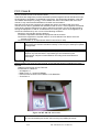
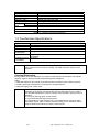
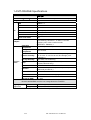
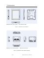
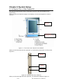
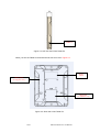
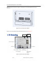
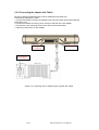
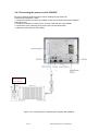
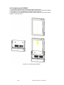
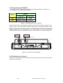
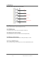
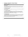
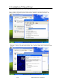
Tablet-PC AMD LX800® M processor-based Point of Care Terminal with 10.4” TFT LCD User’s Manual 1/61 MT-100 Tablet PC User Manual FCC Class B This equipment has been tested and found to comply with the limits for a Class B digital device, pursuant to Part 15 of the FCC Rules. These limits are designed to provide reasonable protection against harmful interference when the equipment is operated in a residential environment. This equipment generates, uses and can radiate radio frequency energy. If not installed and used in accordance with this user's manual, it may cause harmful interference to radio communications. Note that even when this equipment is installed and used in accordance with this user's manual, there is still no guarantee that interference will not occur. If this equipment is believed to be causing harmful interference to radio or television reception, this can be determined by turning the equipment on and off. If interference is occurring, the user is encouraged to try to correct the interference by one or more of the following measures: Reorient or relocate the receiving antenna Increase the separation between the equipment and the receiver Connect the equipment to a power outlet on a circuit different from that to which the receiver is connected Consult the dealer or an experienced radio/TV technician for help Warning Any changes or modifications made to the equipment which are not expressly approved by the relevant standards authority could void your authority to operate the equipment. Caution Danger of explosion if battery is incorrectly replaced. Replace only with the same or equivalent type recommended by the manufacturer. Dispose of used batteries according to the manufacturer’s instructions. Packing List Before installing your Point of Care Terminal, ensure that the following materials have been received: Tablet PC series Point of Care Terminal Accessories for Tablet-PC -- AC Adapter x1 -- Battery Pack x1 + screws for Battery -- User's manual & "Drivers and Utilities" in CD-ROM disc -- Touch Pen x1 Figure 1.0 MT-100 and Accessories Warning To prevent electric shock, Do not remove cover. No user serviceable parts inside, refer servicing to qualified personnel. 2/61 MT-100 Tablet PC User Manual Additional Information and Assistance 1. Visit the Advantech websites at www.advantech.com or www.advantech.com.tw where you can find the latest information about the product. 2. Contact your distributor, sales representative, or Advantech's customer service center for technical support if you need additional assistance. Please have the following information ready before you call: Product name and serial number Description of your peripheral attachments Description of your software (operating system, version, application software, etc.) A complete description of the problem The exact wording of any error messages This equipment is a source of electromagnetic waves. Before use please, make sure that there are not EMI sensitive devices in its surrounding which may malfunction therefore. Warning 1. Input voltage rated 100-240 VAC, 47-63 Hz, 1.25-0.5A (AC Adapter), Output Voltage rated 15VDC , max 6.6A 2. Use a 3V @ 195 mA lithium battery (Model No. BR2032) 3. Packing: please carry the unit with both hands, handle with care 4. Our European representative: Advantech Europe GmbH Kolberger Straße 7 D-40599 Düsseldorf, Germany Tel: 49-211-97477350 Fax: 49-211-97477300 5. Maintenance: to properly maintain and clean the surfaces, use only approved products or clean with a dry applicator Safety Instructions 1. Read these safety instructions carefully. 2. Keep this User's Manual for later reference. 3. Disconnect this equipment from any AC outlet before cleaning. Use a damp cloth. Do not use liquid or spray detergents for cleaning. 4. For plug-in equipment, the power outlet socket must be located near the equipment and must be easily accessible. 5. Keep this equipment away from humidity. 6. Put this equipment on a reliable surface during installation. Dropping it or letting it fall may cause damage. 7. The openings on the enclosure are for air convection. Protect the equipment from overheating. DO NOT COVER THE OPENINGS. 8. Make sure the voltage of the power source is correct before connecting the equipment to the power outlet. 9. Position the power cord so that people cannot step on it. Do not place anything over the power cord. 10. All cautions and warnings on the equipment should be noted. 11. If the equipment is not used for a long time, disconnect it from the power source to avoid damage by transient over voltage. 12. Never pour any liquid into an opening. This may cause fire or electrical shock. 13. Never open the equipment. For safety reasons, the equipment should be opened only by qualified service personnel. 14. If one of the following situations arises, get the equipment checked by service personnel: a. The power cord or plug is damaged. b. Liquid has penetrated into the equipment. c. The equipment has been exposed to moisture. d. The equipment does not work well, or you cannot get it to work according to the user's manual. e. The equipment has been dropped and damaged. f. The equipment has obvious signs of breakage. 15. DO NOT LEAVE THIS EQUIPMENT IN AN UNCONTROLLED ENVIRONMENT WHERE THE STORAGE TEMPERATURE IS BELOW -20° C (-4° F) OR ABOVE 60° C (140° F). THIS MAY DAMAGE THE EQUIPMENT. 3/61 MT-100 Tablet PC User Manual 16. If your computer is losing dramatic time or the BIOS configuration reset to default, the battery has no power. Caution 1. Do not replace battery yourself. Please contact a qualified technician or your retail. 2 .The computer is provided with a battery-powered real-time clock circuit. There is a danger of explosion if battery is incorrectly replaced. Replace only with same or equivalent type recommended by the manufacture. Discard used batteries according to the manufacturer’s instructions 17. IMPROPER INSTALLATION OF VESA MOUNTING CAN RESULT IN SERIOUS PERSONAL INJURY! VESA mount installation should be operated by professional technician, please contact the service technician or your retail if you need this service. 18. CLASSIFICATION: Supply Class I adapter No applied part IPX0 Continuous Operation Not AP or APG category 19. Disconnect device: Appliance inlet. 20. Follow the national requirement to dispose unit. 21. Maintenance: to properly maintain and clean the surfaces, use only the approved products or clean with a dry applicator. 22. Contact information: No.1, Alley 20, Lane 26, Reuiguang Road Neihu District, Taipei, Taiwan 114, R.O.C. TEL: +886 2-27927818 23. 24. This equipment shall not be used for life support system. 25. Accessory equipment connected to the analog and digital interfaces must be in compliance with the respective nationally harmonized IEC standards (i.e. IEC 60950 for data processing equipment, IEC 60065 for video equipment, IEC 61010-1 for laboratory equipment, and IEC 60601-1 for medical equipment.) Furthermore all configurations shall comply with the system standard IEC 60601-1-1. Everybody who connects additional equipment to the signal input part or signal output part configures a medical system, and is therefore, responsible that the system complies with the requirements of the system standard IEC 60601-1-1. The unit is for exclusive interconnection with IEC 60601-1 certified equipment in the patient environment and IEC 60XXX certified equipment outside of the patient environment. If in doubt, consult the technical services department or your local representative. 26. User not to contact SIP/SOPs and the patient at the same time. 27. The sound pressure level at the operator's position according to IEC 704-1:1982 is no more than 70dB (A). DISCLAIMER This set of instructions is given according to IEC 704-1. Advantech disclaims all responsibility for the accuracy of any statements contained herein 4/61 MT-100 Tablet PC User Manual Explanation Of Graphical Symbols: This symbol warns user that uninsulated voltage within the unit may have sufficient magnitude to cause electric shock. Therefore, it is dangerous to make any kind of contact with any part inside this unit. This symbol alerts the user that important literature concerning the operation and maintenance of this unit has been included. Therefore, it should be read carefully in order to avoid any problems. Stand-by Direct Current 5/61 MT-100 Tablet PC User Manual Chapter 1General Information 1.0 Introduction The Tablet PC is a multimedia AMD® Mobile processor-based computer that is designed to serve as a Point of Care terminal (POC.) It is a PC-based system with 10.4" color TFT LCD display and 18-bit stereo audio controller. Tablet PC is a mobile point of care for system integrators, this simple, complete and highly integrated multimedia system lets you easily build a Point of Care Terminal into your applications. Common industrial applications include factory automation systems, precision machinery, and production process control. It is also suitable for many non-industrial applications, including interactive kiosk systems, entertainment management, and car park automation. The Tablet PC is a reliable, costeffective solution to your application's processing requirements. 1.1 Specifications MT-100 Description OS MS XP SP2, XP Embedded Dimension (W×D×H) 266.4 x 211.4 x 36 mm (10.49” x 8.32” x 1.42”) Weight 2.0 kg Panel 10.4" SVGA or XGA TFT Touch Panel Resister touch CPU AMD LX800 500MHz L2 cache 128K Chipset AMD LX800/ CS6635 BIOS Award 512 KB Flash BIOS, supports Plug & Play, APM CMOS Battery (BIOS) 3.0 V @ 195 mA lithium battery DRAM 512MB/1GB DDR333 (One memory module support) AMD LX800 with share memory Supports LVDS LCD panel resolutions up to 1024 x 768 Simultaneously supports CRT 1.8" IDE HDD CF memory Option (trade off with HDD) Graphic Storage Communication Wireless Bluetooth 5x function key Keypad I/O Internal mini-PCI 802.11b/g WLAN Option USB USB2.0 x 2 Power switch Yes DC-in Cradle Yes Docking AC97 Audio I/F Integrated speakerx1, Microphone x1 Model: MT-BATE Removable 11.1V@4800mAh Li-ion battery pack support warm swappable Audio Power Battery Alarm 10% Low battery 6% Critical low Discharge Time 3 hours battery life Charging Time 3.5 hours 6/61 MT-100 Tablet PC User Manual Environment Adapter Model: MPU100-106 Auto-switching 100-240VAC, 47-63Hz, 1.25-0.5A Supplying 15VDC with a current of 6.6A Certification : EN60601-1 Operation Temperature 10 ~ 40°C (32 ~ 104 °F) Storage Temperature -20°C to 60°C Relative humidity 10 °C to 40 °C / 20% RH to 90% RH operating -20 °C to 50 °C/ 10% RH to 95% RH Storage ( Noncondensing ) Storage Humidity 0% to 95% non-condensing Drop 3 Foot height free drop still survive, (test surface: concrete, base unit only) Shock 10G, half sine, 11 msec duration Vibration 0.047 double amplitude displacement ( 5~32Hz) 0.5G Peak (32 -500 Hz ) Power MTBF 100,000 hrs Operational: 6,000 feet; Shipping : 40,000 feet Altitudes Contact: 8Kv Electrostatic Air: 15Kv Discharge (ESD) This device bears the CE label in accordance with the provisions of the EMC Directive 89/336/EMC and the Low Voltage Directive 73/23/EEC. Agency Approvals Option Modules EMC CE, FCC approved Safety HDD UL60601-1 and EN60601-1 approved. 1.8", 40GB~120GB, 4200rpm, PATA HDD CF 2GB/4GB/8GB, Industry (2GB support XP embedded only) Memory 512MB/1GB, DDR-333MHz SoDIMM Digital camera 1.3M Camera Module Yes USB x4, RS-232x1, LAN x1, VGA x1, Smart card MT-CRADLE readerx1 Table 1.1: MT-100 Tablet specification Bluetooth 1.2 LCD Panel Specifications LCD model (MT-100-AE) Display type Size (Diagonal) Resolution Maximum colors Pixel pitch (mm) Horizontal viewing angle Vertical viewing angle Luminance (cd/m2) Contrast ratio Lamp lifetime 7/61 AU G104SN03 TFT color LCD 10.4” 800 x 600 (VGA) 262k color 0.264(H) x 0.264(V) Right 60 degree, Left 60 degree (type) Upper 35 degree, Down 65 degree (type) 230 cd/m2 (type) 500:1 50,000 hours at 6.5mA Table 1.2: AU LCD Panel specification MT-100 Tablet PC User Manual LCD model (MT-100-TE) Toshiba LTD104KA1S Display type TFT color LCD Size (Diagonal) 10.4” Resolution 1024(W) x 768(H) pixels ( XGA) Maximum colors 256K(R,G,B 6 bit color data) Pixel pitch (mm) 0.2055(W) x 0.2055(H) viewing (Upper+Lower) 50 degree angle (Left+Right) 90 degree Luminance (cd/m2) 170 cd/m2 Contrast ratio 250:1 Lamp lifetime 50,000 hours at 6.5mA Table 1.3: Toshiba LCD Panel specification 1.3 Touchscreen Specifications Type Resolution Light Transmission Controller Power Consumption Software Driver Durability (touches in a lifetime) Analog Resistive Continuous 75% USB interface +5V@100 mA Supports Windows® XP Professional, Windows® XP Tablet Edition compatible. 30 million Table 1.4: Touch screen specification Note The Point of Care Terminal with the optionally installed touchscreen will share USB. Once the touch screen is installed, one USB cannot be used for other purposes. Cleaning/Disinfecting During normal use of the Tablet PC may become soiled and should, therefore, be cleaned regularly. Agents: Green tinctured soap and Enzymatic detergents Steps: 1. Wipe the Tablet PC with a clean cloth that has been moistened in the cleaning solution. 2. Prepare agent per manufacturer’s instructions or hospital protocol. 3. Wipe thoroughly with a clean cloth Cautions Do not immerse or rinse the Tablet PC and its peripherals. If you accidentally spill liquid on the device, disconnect the unit from the power source. Contact your Biomed regarding the continued safety of the unit before placing it back in operation. Do not spray cleaning agent on the chassis. Do not use disinfectants that contain phenol. Do not autoclave or clean the MT-100 or its peripherals with strong aromatic, chlorinated, ketone, ether, or Esther solvents, sharp tools or abrasives. Never immerse electrical connectors in water or other liquids. 8/61 MT-100 Tablet PC User Manual 1.4 MT-CRADLE Specifications MT-CRADLE Description Dimension (W×D×H) 217.4 x 156.8 x 42.4 mm (8.56” x 6.17” x 1.67”) Weight 800g I/O USB USB2.0 x 4 COM RS-232 x 1 LAN Giga Bit Ethernet x1 VGA VGA output port x1 DC-in Yes Cradle Ports Docking Smart Card reader Yes Model: MPU100-106 Auto-switching 100-240VAC, 47-63Hz, 1.25-0.5A Supplying 15VDC with a current of 6.6A Certification : EN60601-1 Adapter Operation Temperature Environment 0 ~ 40°C (32 ~ 104 °F) Storage Temperature -20°C to 60°C Relative humidity 10 °C to 40 °C / 20% RH to 90% RH operating -20 °C to 50 °C/ 10% RH to 95% RH Storage ( Noncondensing ) Storage Humidity 0% to 95% non-condensing Drop 3 Foot height free drop still survive, (test surface: concrete, base unit only) Shock 10G, half sine, 11 msec duration Vibration 0.047 double amplitude displacement ( 5~32Hz) 0.5G Peak (32 -500 Hz ) Power MTBF 100,000 hrs Operational: 6,000 feet; Shipping : 40,000 feet Altitudes Contact: 8Kv Electrostatic Air: 15Kv Discharge (ESD) This device bears the CE label in accordance with the provisions of the EMC Directive 89/336/EMC and the Low Voltage Directive 73/23/EEC. Agency Approvals EMC Safety 9/61 CE, FCC approved UL60601-1 and EN60601-1 approved. Table 1.5: MT-CRADLE specification MT-100 Tablet PC User Manual 1.5 Dimensions Dimensions :266.4 x 211.4 x 36 mm ; VESA mount 75 x75mm Figure 1-1: Dimensions of the Tablet PC Dimensions : 217.4 x 156.8 x 42.4 mm ; VESA mount 75 x75 mm Figure 1-2: Dimensions of the CRADLE (Optional) 10/61 MT-100 Tablet PC User Manual Chapter 2 System Setup 2.1 A Quick Tour of the Tablet PC Before you start to set up the Tablet PC, take a moment to become familiar with the locations and purposes of the controls, drives, connections and ports, which are illustrated in the figures below. When you place the Tablet PC upright on the desktop, its front panel appears as shown in Figure 2-1. MT-100 Tablet PC MT-CRADLE CRADLE (optional) Figure 2-1: Front View of the Tablet PC with CRADLE When you look at the left side of the panel PC, you will see the power button on the top view. Figure 2-2. Power ON Switch Speaker USB Port Figure 2-2: Left side view of the Tablet PC When you look at the right side of the panel PC, you will see the USB port. Figure 2-3. 11/61 MT-100 Tablet PC User Manual USB Port Figure 2-3: Left side view of the Tablet PC When you turn the Tablet PC around and look at its rear cover. Figure 2-4. Rating Label Battery Pack (for Engineer only) HDD Door For Maintain only Figure 2-4: Rear view of the Tablet PC 12/61 MT-100 Tablet PC User Manual The optional Docking device : MT-CRADLE When you place the CRADLE upright on the desktop, its front panel appears as shown in Figure 2-5. Figure 2-5: Front View of the CRADLE When you turn the CRADLE around and look at its rear cover. Figure 2-6. Switch Button Figure 2-6: Rear View of the CRADLE 13/61 MT-100 Tablet PC User Manual 2.2 Installation Procedures 2.2.1 Powering the Tablet PC by Battery Power The MT-100 tablet PC is supplied with a powerful rechargeable battery. To install and maintain the battery, or if it needs to be replaced, follow the instructions in this section. Caution! Do not attempt to replace the battery with any others than the models recommended and manufactured specifically for this tablet PC. Note! Before using MY-100 Tablet PC, please connect the adapter into MT-100 to charge the battery and backup battery at least 24Hrs. 2.2.1.1 Installing a Battery The battery is designed specifically for installation with the MT-100 tablet PC. It fits exactly into the back of the PC and delivers precisely the exact voltage required to power the unit. Under normal conditions, a fully charged battery will power the PC for up to 3.5 hours. Normally, it requires 3.0 hours to fully charge a new battery. z To install or replace the battery pack: 1. Turn off the MT-100 2. Disconnect any peripheral devices from the MT-100. 3. Unfasten the two screws and pull back then can remove the battery. 4. Insert the new battery pack in the battery room. Figure 2-7: Inserting the battery pack 14/61 MT-100 Tablet PC User Manual 5. Push up the battery pack to close connection with system. Figure 2-8: Push up the battery pack to close 5. Fasten the two battery cover screws. Figure 2-9: Replacing the battery cover screws 15/61 MT-100 Tablet PC User Manual 2.2.2 Connecting the adapter with Tablet Be sure to always handle the power cords by holding the plug ends only. Follow these procedures in order: 1. Connect the female end of the AC Adapter cord to the DC Power inlet of the Tablet PC. (See Figure 2-5.) 2. Connect the female end of the power cord to the AC inlet of the AC Adapter 3. Connect the 3-pin male plug of the power cord to an electrical outlet. 4. Open the power switch on AC Adapter. Docking Port for CRADLE DC Power Inlet Power Switch of AC adapter Figure 2-5: Connecting the AC Adapter power supplier with Tablet 16/61 MT-100 Tablet PC User Manual 2.2.3 Connecting the power cord for CRADLE Be sure to always handle the power cords by holding the plug ends only. Follow these procedures in order: 1. Connect the female end of the AC Adapter cord to the DC Power inlet of the CRADLE. (See Figure 2-6.) 2. Connect the female end of the power cord to the AC inlet of the AC Adapter 3. Connect the 3-pin male plug of the power cord to an electrical outlet. 4. Open the power switch on AC Adapter. Power Switch of AC adapter Figure 2-6: Connecting the AC Adapter power supplier with CRADLE 17/61 MT-100 Tablet PC User Manual 2.2.4 Connecting the keyboard and mouse Connect the USB port to the USB mouse and keyboard port on the I/O section of the Tablet PC. (See Figure 2-7.) Figure 2-7: Connecting the Keyboard or Mouse 18/61 MT-100 Tablet PC User Manual 2.2.4 Combining with CRADLE 1. The CRADLE must be fixed on VESA mount(75mmx75mm) first. 2. Connect the female end of the AC Adapter cord to the DC Power inlet of the CRADLE. 3. The Tablet PC must vertical landing to CRADLE (See Figure 2-8.) 4. The button on up of CRADLE down and switch off then Tablet PC can vertical takeoff CRADLE . (See Figure 2-8) Figure 2-8: Combining with CRADLE 19/61 MT-100 Tablet PC User Manual 2.2.5 Separating with CRADLE 1. The Switch must on “Right side” and Button push down (see table 2-1 & Figure 2-9.) 2. The Tablet PC can vertical takeoff CRADLE . Switch Button Left side Right side High Always lock lock Low Always un-lock un-lock Table 2-1: The selection of Lock of CRADLE Remark: If the switch on the left side then Button mode can’t be changed so Always Lock or Always un-lock. You must change the switch to right side then can change the Button mode. Notice: “Always un-lock” and “un-lock” can’t guaranty the connection quality with CRADLE. Meaning is the CRADLE I/O ports can’t workable if no good connection. Button Switch Left Side Right Side Figure 2-9: Top down view of CRADLE 2.2.6 Switching on the power Switch on the power switch on the left side. Press the power switch button over 0.5 sec then can power on the system. 20/61 MT-100 Tablet PC User Manual 2.3 LED Signals The MT-100 is equipment with a set of Light Emitting Diodes(LEDs) located along the right top of the front Bezel. Battery Status LED Power ON/OFF LED 2.3.1 Power ON/OFF LED z z z Dark : No DC-in from AC adapter Static Green : DC-in from AC adapter Blinking Green: System is in standby mode with AC Adapter DC-in. 2.3.2 Battery Status LED z z z Dark : Battery is fully charged (if the system is powered by Adapter) Battery capacity is sufficient and above the “Low Battery Alarm”(If the system is powered by battery) ( Default for the “Low Battery Alarm” is less than 10% of normal capacity.) Static Green : Battery is under charging (If the system is powered by adapter) Blinking Green: Battery is under 10% of the normal capacity 21/61 MT-100 Tablet PC User Manual 2.3.3 CRADLE Status LED Docking Status LED Power ON/OFF LED 2.3.4 Power ON/OFF LED z z Dark : No Power input Static Green : the CRADLE is powered by adapter 2.3.5 Docking Status LED z z Dark : No Power input or Docking status is no or NO good. (if the system is powered by Adapter) Static Green : Docking status is good with Tablet PC (If the system is powered by adapter) 2.3.6 Caution message on CRADLE Caution! Do not touch the metal pin of Docking by finger, conductivity material , and liquid. The user not to touch the any connectors of the apparatus and the patient simultaneously. It will lead the system crash. 22/61 MT-100 Tablet PC User Manual 2.4 Buttons The hotkey button on right down side of front bezel. UP Down Keyboard on Screen Display rotation Touch ON/OFF Button 2.4.1 UP button The “UP” button function is same as Keyboard “UP” key. 2.4.2 DOWN button The “DOWN” button function is same as Keyboard “DOWN” key. 2.4.3 Keyboard on Screen button The keyboard button function can enable On-Screen Keyboard utility. 2.4.4 Display rotation button The rotation button function is the hotkey for rotating the display on screen. 2.4.5 Touch ON/OFF button The Touch button function is the hotkey for touch screen enable/disable function. 23/61 MT-100 Tablet PC User Manual 2.5 Running the BIOS Setup Program Your Tablet PC is likely to have been properly set up and configured by your dealer prior to delivery. You may still find it necessary to use the BIOS (Basic Input-Output System) setup program to change system configuration information, such as the current date and time or your type of hard drive. The setup program is stored in read-only memory. It can be accessed either when you turn on or reset the panel PC, by pressing the " Crtl+Alt+Del " key on your keyboard immediately after powering on the computer. The settings you specify with the setup program are recorded in a special area of memory called CMOS RAM. This memory is backed up by a battery so that it will not be erased when you turn off or reset the system. Whenever you turn on the power, the system reads the settings stored in CMOS RAM and compares them to the equipment check conducted during the power on self-test (POST). If an error occurs, an error message will be displayed on screen, and you will be prompted to run the setup program. 2.6 Installing System Software Recent releases of operating systems from major vendors include setup programs which load automatically and guide you through hard disk preparation and operating system installation. The guidelines below will help you determine the steps necessary to install your operating system on the panel PC hard drive. Note Some distributors and system integrators may have already pre-installed system software prior to shipment of your panel PC. If required, insert your operating system's installation or setup diskette into the optical drive until the release button pops out. (See Figure 2-14) The BIOS supports system boot-up directly from the CD-ROM drive. You may also insert your system installation CD-ROM disk into the CD-ROM drive.. Power on or reset the system by pressing the "Ctrl"+"Alt"+"Del" keys simultaneously. The Point of Care Terminal will automatically load the operating system from the diskette or CDROM. If you are presented with the opening screen of a setup or installation program, follow the instructions on screen. The setup program will guide you through preparation of your hard drive, and installation of the operating system. 24/61 MT-100 Tablet PC User Manual 2.8 Installing the Drivers After installing your system software, you will be able to set up the Ethernet, SVGA, audio and touch screen functions. All the drivers except the CD-ROM drive driver are stored in a CDROM disc entitled "Drivers and Utilities which can be found in your accessory box. The standard procedures for installing the Ethernet, SVGA, audio and touch screen drivers are described in Chapters 3, 4, 5, 6 and 7 respectively. The utility directory includes multimedia programs. Refer to the README.TXT file inside the VGA folders for more detailed information. The various drivers and utilities in the CD-ROM disc have their own text files which help users install the drivers and understand their functions. These files are a very useful supplement to the information in this manual. For your reference, the directory of drivers on the "Drivers and Utilities" CD-ROM is: Figure 2-5: The file directory on "Drivers and Utilities" CD-ROM Note The drivers and utilities used for the MT-100 panel PCs are subject to change without notice. If in doubt, check Advantech's website or contact our application engineers for the latest information regarding drivers and utilities. 25/61 MT-100 Tablet PC User Manual Chapter 3 Graphic chipset Setup 3.1 Introduction The MT-100 has an onboard VGA interface. The specifications and features are described as follows: 3.1.1 Chipset The MT-100 uses Mobile AMD LX800 /CS5336 chipset for its graphic controller. It supports SDVO device, and CRT monitors. The Mobile AMD LX800 /CS5336 chipset is a component of the AMD® mobile technology. 3.1.2 Display memory Max memory allocation support based on total system memory 1-MB or 8 MB of pre-allocated memory supported. 3.1.3 LVDS Transmitter The MT-100 uses Chrontel CH7308A for driving its LCD panel. The CH7308A is a display controller device, which accepts digital graphics input signals, upscales, encodes, and transmits data through an LVDS transmitter to a LCD panel. The CH7308A operates at pixel rates of up to 140MHz, and support 18-bit/24-bit LCD panels. 3.1.4 Display types CRT and panel displays can be used simultaneously. The MT-100 can be set in one of three configurations: CRT only, LVDS only, both CRT and LFP (LVDS). The system is initially set to simultaneous display mode - CRT and LFP (BIOS default setting). Analog CRT DAC interface supports max DAC frequency up to 400 MHz, 24-bit RAMDAC, DDC2B compliant, and resolution up to 2048 x 1536. 26/61 MT-100 Tablet PC User Manual 3.2 Installation of Chipset Driver Complete the following steps to install the chipset driver. Follow the procedures in the flow chart that apply to the operating system that you are using within your MT-100. Step 1-1 Click the 'Start' button in the task bar, click 'Control Panel', click 'System' then show a dialogue windows of System Properties. Then Click the 'Hardware', Click 'Device Manager'. The Install dialog will appear. Step 1-2 Click the ‘Crypto devices’ then double Click the ‘Entertainment Encryption/Decryption Controller’. Appear a New dialog then Click the ‘Driver’, Select ‘Update Driver’ will show as below dialog.. 27/61 MT-100 Tablet PC User Manual Step 1-3 Click the Circle of ‘Yes, this time only ‘ then Click ‘Next’ step. Please Click the Circle of ‘Install from a list or specific location (Advanced). Step 1-4 Click the ‘Include this location in the search’. Then Browse the direction of D:\CHIPSET\AES’ then Click ‘Next’. 28/61 MT-100 Tablet PC User Manual Step 1-5 The system will auto install the Chipset drive as below window. Step 1-6 Please direct to ‘D:\CHIPSET\AES’ then Click ‘OK’ if need more information for installation. 29/61 MT-100 Tablet PC User Manual Step 1-7 When appear the ‘Completing the Hardware update Wizard’ dialog then can Click the ’Finish’ button to complete it. Important The following windows illustrations are examples only. You must follow the flow chart instructions and pay attention to the instructions which appear on your screen. Note1 The CD-ROM drive is designated as “D:” throughout this chapter. Note2 <Enter> means pressing the “Enter” key on the keyboard. Note3 Before you install the graphic driver of MT-100, please ensure you have installed the “AMD Chipset Software Installation Utility”. You can find this driver in the Utility CD-ROM. Note4 The resolution of window display will be fix on 640 x 480 before you install VGA driver. Depend on your LCD native resolution, the black area might be different. 30/61 MT-100 Tablet PC User Manual 3.3 Installation of Graphic Driver Complete the following steps to install the SVGA driver. Follow the procedures in the flow chart that apply to the operating system that you are using within your MT-100. Step 1-1 Click the 'Start' button in the task bar, click 'Control Panel', click 'System' then show a dialogue windows of System Properties. Then Click the 'Hardware', Click 'Device Manager' then appear the ‘Device manager’ dialog. Step 1-2 Click the ‘Display adapters’ then double Click the ‘VGA’ exist under Display adapters. Appear a New dialog then Click the ‘Driver’, Select ‘Update Driver’ will show as below dialog.. 31/61 MT-100 Tablet PC User Manual Step 1-3 Click the Circle of ‘Yes, this time only ‘ then Click ‘Next’ step. Please Click the Circle of ‘Install from a list or specific location (Advanced). Step 1-4 Click the ‘Include this location in the search’. Then Browse the direction of ‘D:\VGA\GeodeLX_XP_XPe_Graphics _v3.03.06’ then Click ‘Next’. 32/61 MT-100 Tablet PC User Manual Step 1-5 The system will auto install the Chipset drive as below window. Step 1-6 Please select ‘Continue Anyway’. 33/61 MT-100 Tablet PC User Manual Step 1-7 System automatic to install the VGA drive as below window. Step 1-8 Please direct to ‘D:\VGA\GeodeLX_XP_XPe_Graphics _v3.03.06’ then Click ‘OK’ if need more information for installation. 34/61 MT-100 Tablet PC User Manual Step 1-9 When appear the ‘Completing the Hardware update Wizard’ dialog then can Click the ’Finish’ button to complete it. Important The following windows illustrations are examples only. You must follow the flow chart instructions and pay attention to the instructions which appear on your screen. Note1 The CD-ROM drive is designated as “D” throughout this chapter. Note2 <Enter> means pressing the “Enter” key on the keyboard. Note3 Before you install the graphic driver of MT-100, please ensure you have installed the “AMD Chipset Software Installation Utility”. You can find this driver in the Utility CD-ROM. Note4 The resolution of window display will be fix on 640 x 480 before you install VGA driver. Depend on your LCD native resolution, the black area might be different. 35/61 MT-100 Tablet PC User Manual 3.4 Installation of Audio Driver Complete the following steps to install the Audio driver. Follow the procedures in the flow chart that apply to the operating system that you are using within your MT-100. Important The following windows illustrations are examples only. You must follow the flow chart instructions and pay attention to the instructions which appear on your screen. Note1 The CD-ROM drive is designated as “D” throughout this chapter. Note2 <Enter> means pressing the “Enter” key on the keyboard. Step 1-1 Click the 'Start' button in the task bar, click 'Control Panel', click 'System' then show a dialogue windows of System Properties. Then Click the 'Hardware', Click 'Device Manager' then appear the ‘Device manager’ dialog. 36/61 MT-100 Tablet PC User Manual Step 1-2 Click the ‘Sound, Video and Game controllers’ then double Click the ‘Multimedia Audio Controller’. Appear a New dialog then Click the ‘Driver’, Select ‘Update Driver’ will show as below dialog. Step 1-3 Click the Circle of ‘Yes, this time only ‘ then Click ‘Next’ step. Please Click the Circle of ‘Install from a list or specific location (Advanced). 37/61 MT-100 Tablet PC User Manual Step 1-4 Click the ‘Include this location in the search’. Then Browse the direction of ‘D:\AUDIO\Audio’ then Click ‘Next’. Step 1-5 System will automatic to install the Chipset drive as below window. 38/61 MT-100 Tablet PC User Manual Step 1-6 Please select ‘Continue Anyway’. Step 1-7 Please direct to ‘D:\AUDIO\Audio’ then Click ‘OK’ if need more information for installation. 39/61 MT-100 Tablet PC User Manual Step 1-8 System will continuing install the Chipset drive as below window. Step 1-9 When appear the ‘Completing the Hardware update Wizard’ dialog then can Click the ’Finish’ button to complete it. 40/61 MT-100 Tablet PC User Manual 3.4.1 Further information For further information about the CHIPSET, VGA , AUDIO installation in your MT-100, included Driver updates, troubleshooting guides and FAQ lists please visit the following web resources. AMD website: www.AMD.com Advantech websites: www.advantech.com 41/61 MT-100 Tablet PC User Manual Chapter 4 Touch screen Interface 4.1 Introduction 4.1.1 General Information The MT-100's optional touch screen incorporates advanced second-generation 5-wire resistive technology. They allow 75% light transmission respectively. The resistive and capacitive models have an antiglare surface. All models provide greatly enhanced visual resolution. They also have new improved scratch-resistant features. The touch screen is manufactured from UL-recognized components. When properly installed, the touch screen's ball impact resistance meets the UL 1950 standard. Its fire resistance meets the UL-746C, 19 mm (0.75") flame test standard. Systems incorporating the touch screen, controllers, and cables have been approved to FCC Class A and Class B standards. 4.1.2 General specifications Please refer to Chapter 1, Section 1.2 of this manual. 4.1.3 Environmental specifications Temperature: -0° ~ 40° C (operating) -20° ~ 60° C (storage) Relative humidity: 90 RH at 35° C (operating) 90 RH at 35° C for 240 hours, non-condensing (storage) Chemical resistance: The active area of the touch screen is resistant to the following chemicals when exposed for a period of one hour at a temperature of 21° C (71° F): - Acetone - Methylene chloride - Methyl ethyl ketone - Isopropyl alcohol - Hexane - Ammonia-based glass cleaners - Turpentine - Mineral spirits - Foods and beverages 4.2 Installation of Driver for Touchscreen MY-100 applies EETI to control touch screen. To facilitate installation of the touch screen driver, you should read the instructions in this section carefully before you attempt installation. Important The following windows illustrations are examples only. You must follow the flow chart instructions and pay attention to the instructions which appear on your screen. Note1 The external CD-ROM drive is designated as “D” throughout this chapter. Note2 <Enter> means pressing the “Enter” key on the keyboard. 42/61 MT-100 Tablet PC User Manual 4.2.1 Installation for Windows 2000/XP 4.3 Further information For further information about the Touchscreen installation in your MT-100, included Driver updates, troubleshooting guides and FAQ lists please visit the following web resources. ELO website: http://www.elotouch.com/ EETI website: http://www.eeti.com.tw/ Advantech websites: www.advantech.com 43/61 MT-100 Tablet PC User Manual Chapter 5 Hotkey function Application 5.1 Introduction 5.1.1 General Information The MT-100's features a build in Wireless Ethernet card by MiniPCI interface. Free cable when you surfing web screen, Display rotation and T/S on/off button. There Hotkey can customize if customer have request for it. 5.1.2 Install Hotkey AP Important The following windows illustrations are examples only. You must follow the flow chart instructions and pay attention to the instructions which appear on your screen. Note1 The CD-ROM drive is designated as “D” throughout this chapter. Note2 <Enter> means pressing the “Enter” key on the keyboard. Step 1-1 Click the ‘Include this location in the search’. Then Browse the direction of ‘D:\Hotkey\Advantech MT-100 Hotkey V1.10’ then double Click ‘Setup’. 44/61 MT-100 Tablet PC User Manual Step 1-2 Wait for the AP automatic install. Step 1-3 Press the “Next” when show the window. 45/61 MT-100 Tablet PC User Manual Step 1-4 Please select the “ I accept the term of the license agreement” then press ”Next”. Step 1-5 AP will keep going to implement it. 46/61 MT-100 Tablet PC User Manual Step 1-6 Press the “Finish” button when show the Complete window. 47/61 MT-100 Tablet PC User Manual Chapter 6 WLAN driver installation 6.1 Introduction 6.1.1 General Information Step 1-1 Click the ‘Include this location in the search’. Then Browse the direction of ‘D:\WLAN\ 080229_RT61_D_1.2.3.0_VA_2.1.0.0_RaUI_2.0.7.0_VA_2.0.9.0_for 2K&XPx86 VAx86’ then double Click it. 48/61 MT-100 Tablet PC User Manual Step 1-2 The WLAN drivers will auto download file then show the License window. Please select the “ I accept the term of the license agreement” then press ”Next”. Step 1-3 Select the “Ralink Corporation Tool” then Press ‘Next’. 49/61 MT-100 Tablet PC User Manual Step 1-4 Select the ‘Optimize WiFi mode’ then Press ‘Next’. Step 1-5 Select the ‘Install’ 50/61 MT-100 Tablet PC User Manual Step 1-5 Auto install driver Step 1-6 Driver implement complete, Please press the ‘Finish’ button. 51/61 MT-100 Tablet PC User Manual Step 1-7 Ralink WLAN utility user interface . 6.1 Further information For further information about the WLAN card installation in your MT-100, included Driver updates, troubleshooting guides and FAQ lists please visit the following web resources. RaLink website: http://www.Ralink.com.tw/ Advantech websites: www.advantech.com 52/61 MT-100 Tablet PC User Manual Chapter 7 MT-CRADLE drivers installation 7.1 Introduction 7.1.1 General Information MT-CRADLE is MT-100 tablet PC series option Docking station. It is include multi I/O port for more application. These I/O port include USB x 4 ports, RS-232 Port x1, Gigabit LAN port x1, VGA port and Smart Card Reader. We must install drivers for these add on I/O ports then by be 1. The CRADLE must be fixed on VESA mount(75mmx75mm) first. 2. Connect the female end of the AC Adapter cord to the DC Power inlet of the CRADLE. 3. The Tablet PC must vertical landing to CRADLE (See Figure 7-1.) 4. The button on up of CRADLE down and switch off then Tablet PC can vertical takeoff CRADLE . Figure 7-1: Combining with CRADLE 53/61 MT-100 Tablet PC User Manual 7.2. USB to LAN driver installation Step 1-1 When you setup the cradle and plug the power in with adapter. The MT-100 tablet PC connect with CRADLE. The SYSTEM will auto detect “Found New Hardware” . The show the “Files needed” windows. Please press the “Browse” . 54/61 MT-100 Tablet PC User Manual Step 1-2 Then Browse the direction of ‘D:\USB-LAN\ F:\AX88772_772A_WinXP2K_32bit_v3.4.3.18_WHQL’ will show the AX88772.sys file. Select it and press the “Open” Button. Step 1-3 Please press the “OK” Button then auto implement the drivers. 55/61 MT-100 Tablet PC User Manual Step 1-4 You can double check after install driver on Device manager. As below red line the driver is available on system. 56/61 MT-100 Tablet PC User Manual 7.2. USB to RS-232 driver installation Step 1-1 Browse the direction of ‘D:\USB to RS-232\wd_pl2303h-hx-x_v20019v2021’ the can find “PL-2303 Driver Installer” file. Then double clock it. Step 1-2 The driver will auto install it. Please select “Yes, I want to reboot computer now” and press the “Finish’ button. System will re-boot. The driver is available. 57/61 MT-100 Tablet PC User Manual 7.3. Smart Card reader driver installation 7.3.1 General Information of Smart card reader • • • • Full speed interface to PC with simple command structure Support most of the popular memory card types in the market: o Cards following the I2C bus protocol (free memory cards) such as: Atmel: AT24C01 / 02 / 04 / 08 / 16 / 32 / 64 / 128 / 256 / 512 / 1024 SGS-Thomson: ST14C02C, ST14C04C Gemplus: GFM1K, GFM2K, GFM4K, GFM8K o SLE4432/4442/5542 intelligent 256 bytes EEPROM with write protect function: SLE4432, SLE4442, SLE5542 o SLE4418/4428 intelligent 1K bytes EEPROM with write-protect function: SLE4418, SLE4428 Short Circuit Protection Certificate of conformance: EN 60950/IEC 60950, ISO-7816, PC/SC, CE, FCC, Microsoft WHQL, EMV 2000 Level 1certified 7.3.2 Install Smart card reader driver Important The following windows illustrations are examples only. You must follow the flow chart instructions and pay attention to the instructions which appear on your screen. Note1 The CD-ROM drive is designated as “D” throughout this chapter. Note2 <Enter> means pressing the “Enter” key on the keyboard. 58/61 MT-100 Tablet PC User Manual Step 1-1 Click the ‘Include this location in the search’. Then Browse the direction of ‘D:\Smart Card Reader\ACR’ then double Click ‘Setup’. Step 1-2 Wait for the AP automatic install. 59/61 MT-100 Tablet PC User Manual Step 1-3 Please select the “Yes” button to continue installation. Step 1-4 Please express the “Finish” button when show the screen. Complete driver installation. 60/61 MT-100 Tablet PC User Manual 7.4.3 Further informatio For further information about the Smart card reader installation in your MT-100, included Driver updates, troubleshooting guides and FAQ lists please visit the following web resources. The model is ACR38. ACS website: http://www.ACS.com.hk Advantech websites: www.advantech.com 61/61 MT-100 Tablet PC User Manual