1
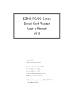
REFERENCE MANUAL ACR30 Advanced Card Systems Ltd. Website: www.acs.com.hk Email: [email protected] ACR30 Table of Contents 1.0. Introduction ............................................................................................................... 5 2.0. Features ..................................................................................................................... 6 3.0. Supported Card Types .............................................................................................. 7 3.1. Memory-based smart cards (synchronous interface) (*) .......................................................7 3.2. Microcontroller-based smart cards (asynchronous interface) ...............................................7 4.0. Smart Card Interface ................................................................................................. 8 4.1. Smart Card Power Supply VCC (C1) ....................................................................................8 4.2. Programming Voltage VPP (C6) ............................................................................................8 4.3. Card Type Selection ..............................................................................................................8 4.4. Interface for Microcontroller-based Cards .............................................................................8 4.5. Card Tearing Protection.........................................................................................................8 5.0. Power Supply ............................................................................................................ 9 6.0. Serial Interface ........................................................................................................ 10 6.1. Communication Parameters ................................................................................................10 6.1.1. Hardware Baud Rate ..................................................................................................10 6.1.2. Software Baud Rate Selection ....................................................................................10 6.2. Interface Wiring ....................................................................................................................10 7.0. USB Interface ........................................................................................................... 12 7.1. Communication Parameters ................................................................................................12 8.0. Communication protocol ........................................................................................ 13 8.1. Command ............................................................................................................................13 Normal Command (Length < 255 bytes) ........................................................................................13 8.1.1. 8.2. Extended Command ...................................................................................................13 Response .............................................................................................................................14 8.2.1. No transmission error with normal response (Length < 255 bytes) ............................14 8.2.2. No transmission error with extended response ..........................................................15 8.2.3. Transmission error ......................................................................................................16 8.3. Reset Message ....................................................................................................................16 8.4. Card Status Message ..........................................................................................................16 8.5. Transmission Protocol .........................................................................................................17 9.0. Commands ............................................................................................................... 19 9.1. Control Commands ..............................................................................................................19 ACR30 Version 3.3 9.1.1. GET_ACR_STAT ........................................................................................................19 9.1.2. SET_PROTOCOL .......................................................................................................20 Reference Manual January 2009 Page 2 of 44 ACR30 9.1.3. SELECT_CARD_TYPE ..............................................................................................21 9.1.4. RESET ........................................................................................................................21 9.1.5. SET_NOTIFICATION ..................................................................................................22 9.1.6. SET_OPTION .............................................................................................................22 9.2. Card Commands ..................................................................................................................23 '104' - type non-reloadable Token Counter Cards (*) .....................................................................23 9.2.1.1. RESET (*)................................................................................................................... 23 9.2.1.2. POWER_OFF (*) ........................................................................................................ 24 9.2.1.3. READ_DATA (*) ......................................................................................................... 24 9.2.1.4. WRITE_DATA (*) ....................................................................................................... 24 9.2.1.5. PRESENT_TRANSPORT_CODE (*) ......................................................................... 25 9.2.1.6. AUTHENTICATE_CARD_SLE4436 (firmware 2.10 onwards) (*).............................. 26 9.2.1.7. AUTHENTICATE_CARD_SLE5536 (firmware 2.10 onwards) (*).............................. 27 9.2.2. I2C-Bus cards (standard and extended addressing) (*) .............................................28 9.2.2.1. RESET (*)................................................................................................................... 28 9.2.2.2. POWER_OFF (*) ........................................................................................................ 28 9.2.2.3. READ_DATA (*) ......................................................................................................... 28 9.2.2.4. WRITE_DATA (*) ....................................................................................................... 29 9.2.3. Siemens SLE 4432/4442 intelligent 256 Byte Memory Card (*) .................................29 9.2.3.1. RESET (*)................................................................................................................... 29 9.2.3.2. POWER_OFF (*) ........................................................................................................ 30 9.2.3.3. READ_DATA (*) ......................................................................................................... 30 9.2.3.4. WRITE_DATA (*) ....................................................................................................... 31 9.2.3.5. WRITE_PROTECTION (*) ......................................................................................... 31 9.2.3.6. PRESENT_CODE (only SLE 4442) (*) ..................................................................... 32 9.2.3.7. CHANGE_CODE (only SLE 4442) (*) ....................................................................... 33 9.2.4. Siemens SLE 4418/4428 intelligent 1K Byte Memory Card (*) ..................................33 9.2.4.1. RESET (*)................................................................................................................... 33 9.2.4.2. POWER_OFF (*) ........................................................................................................ 33 9.2.4.3. READ_DATA (*) ......................................................................................................... 34 9.2.4.4. WRITE_DATA (*) ....................................................................................................... 35 9.2.4.5. WRITE_PROTECTION (*) ......................................................................................... 35 9.2.4.6. PRESENT_CODE (only SLE 4428) (*) ..................................................................... 36 9.2.5. MCU-based Card ........................................................................................................36 9.2.5.1. RESET ....................................................................................................................... 36 9.2.5.2. POWER_OFF............................................................................................................. 37 9.2.5.3. EXCHANGE_APDU ................................................................................................... 37 9.2.5.4. EXCHANGE_T1_FRAME .......................................................................................... 38 ACR30 Version 3.3 Reference Manual January 2009 Page 3 of 44 ACR30 9.2.6. Security Application Module (SAM) (**) ......................................................................38 9.2.6.1. ACTIVATE_SAM (**) .................................................................................................. 38 9.2.6.2. DEACTIVATE_SAM (**) ............................................................................................. 39 9.2.6.3. EXCHANGE_SAM_APDU (**) ................................................................................... 39 9.2.6.4. EXCHANGE_SAM_T1_FRAME (**) .......................................................................... 40 Appendix A: Supported Card Types ................................................................................ 41 Appendix B: Response Status Codes .............................................................................. 42 Appendix C: Technical Specifications ............................................................................. 43 ACR30 Version 3.3 Reference Manual January 2009 Page 4 of 44 ACR30 1.0. Introduction The ACS Smart Card Reader/Writer ACR30 is an interface for the communication between a computer (for example, a PC) and a smart card. Different types of smart cards have different commands and different communication protocols. This prevents in most cases the direct communication between a smart card and a computer. The ACR30 Reader/Writer establishes a uniform interface from the computer to the smart card for a wide variety of cards. By taking care of the card specific particulars, it releases the computer software programmer of getting involved with the technical details of the smart card operation, which are in many cases not relevant for the implementation of a smart card system. The ACR30 Smart Card Reader/Writer is connected to the computer through a serial asynchronous interface (RS-232) or USB interface. The reader accepts commands from the computer, carries out the specified function at the smart card and returns the requested data or status information. NOTE - Although the ACR30 is a true card reader/writer as it can read and write smart cards, the terms card reader or reader will be used indifferently to refer to the ACR30, for the sake of readability and because these designations are commonly in use for this kind of devices. ACR30 Version 3.3 Reference Manual January 2009 Page 5 of 44 ACR30 2.0. Features ISO7816-1/2/3 compatible smart card interface Supports CPU-based cards with T=0 and/or T=1 protocol (*) Supports commonly used memory cards (I2C, SLE4406, SLE4418/28, SLE4432/42) Support PPS (Protocol and Parameters Selection) with 9600 – 96000 bps in reading and writing smart cards RS-232 interface or USB interface to PC with simple command structure Supports memory cards SLE4436 and SLE5536 (firmware 2.10 onwards) Security application modules (SAM) inside the reader supporting CPU-based cards with T=0 and/or T=1 protocol (SAM Reader only) Note (*) – SAM Reader does not support for memory cards ACR30 Version 3.3 Reference Manual January 2009 Page 6 of 44 ACR30 3.0. Supported Card Types The ACR30 can operate MCU card with T=0 and T=1 protocol. The table presented in Appendix A explains which card type selection value must be specified for the various card types supported by the reader. 3.1. Memory-based smart cards (synchronous interface) (*) '104' type EEPROM non-reloadable token counter cards, including: Gemplus GPM103, Siemens SLE 4406 Siemens SLE4436 and SLE5536 (firmware 2.10 onwards) Cards following the I2C bus protocol (free memory cards) with memory capacity up to 16 Kbit and minimum 4 bytes page write capability, including: Atmel AT24C01/02/04/08/16 Gemplus GFM2K, GFM4K SGS-Thomson ST14C02C,14C04C Siemens SLE4432/4442 intelligent 256 bytes EEPROM with write protect function: SLE 4432, SLE 4442 Siemens SLE 4418/4428 intelligent 1K bytes EEPROM with write-protect function: SLE 4418, SLE 4428 NOTE (*) – SAM READER DOES NOT SUPPORT FOR MEMORY-BASED SMART CARD 3.2. Microcontroller-based smart cards (asynchronous interface) The ACR30 supports EEPROM microcontroller-based cards with internal programming voltage (VPP) generation and the following programming parameters transmitted in the ATR: PI1 = 0 or 5 I = 25 or 50 The ACR30 performs the Protocol and Parameters Selection (PPS) procedure as specified in ISO7816-3:1997. When the card ATR indicates the specific operation mode (TA2 present; bit b5 of TA2 must be 0) and that particular mode is not supported by the ACR30, the reader will reset the card to set it to negotiable mode. If the card cannot be set to negotiable mode, the reader will reject the card. When the card ATR indicates the negotiable mode (TA2 not present) and communication parameters other than the default parameters, the ACR30 will execute the PPS and try to use the communication parameters that the card suggested in its ATR. If the card does not accept the PPS, the reader will use the default parameters (F=372, D=1). For the meaning of the aforementioned parameters, please refer to ISO7816, part 3. ACR30 Version 3.3 Reference Manual January 2009 Page 7 of 44 ACR30 4.0. Smart Card Interface The interface between the ACR30 and the inserted smart card follows the specifications of ISO7816-3 with certain restrictions or enhancements to increase the practical functionality of the ACR30. 4.1. Smart Card Power Supply VCC (C1) The current consumption of the inserted card must not be higher than 50mA. 4.2. Programming Voltage VPP (C6) According to ISO 7816-3, the smart card contact C6 (VPP) supplies the programming voltage to the smart card. Since all common smart cards in the market are EEPROM based and do not require the provision of an external programming voltage, the contact C6 (VPP) has been implemented as a normal control signal in the ACR30. The electrical specifications of this contact are identical to those of the signal RST (at contact C2). 4.3. Card Type Selection The controlling PC has to always select the card type through the proper command sent to the ACR30 prior to activating the inserted card. This includes both the memory cards and MCU-based cards. For MCU-based cards the reader allows to select the preferred protocol, T=0 or T=1. However, this selection is only accepted and carried out by the reader through the PPS when the card inserted in the reader supports both protocol types. Whenever an MCU-based card supports only one protocol type, T=0 or T=1, the reader automatically uses that protocol type, regardless of the protocol type selected by the application. 4.4. Interface for Microcontroller-based Cards For microcontroller-based smart cards only the contacts C1 (VCC), C2 (RST), C3 (CLK), C5 (GND) and C7 (I/O) are used. A frequency of 3.6864 / 4 MHz is applied to the CLK signal (C3). 4.5. Card Tearing Protection The ACR30 provides a mechanism to protect the inserted card when it is suddenly withdrawn while it is powered up. The power supply to the card and the signal lines between the ACR30 and the card are immediately deactivated when the card is being removed. As a general rule, however, to avoid any electrical damage, a card should only be removed from the reader while it is powered down. NOTE - The ACR30 does never by itself switch on the power supply to the inserted card. This must explicitly be done by the controlling computer through the proper command sent to the reader. ACR30 Version 3.3 Reference Manual January 2009 Page 8 of 44 ACR30 5.0. Power Supply The ACR30 requires a voltage of 5V DC, 100mA regulated power supply. The ACR30 gets the power supply from PC (through the cable supplied along with each type of reader). Status LEDs- Green LED on the front of the reader indicates the activation status of the smart card interface. Green LED - Indicates power supply to the smart card is switched on, i.e., the smart card is activated. ACR30 Version 3.3 Reference Manual January 2009 Page 9 of 44 ACR30 6.0. Serial Interface The ACR30 is connected to a computer through a serial asynchronous interface following the RS-232 standard. 6.1. Communication Parameters The following communication parameters are used by the ACR30 and cannot be modified by the host computer: Transmission protocol : serial asynchronous Parity : none Data Bits : 8 Stop Bits : 1 The ACR30 provides two means to select the transmission speed (baud rate) used by the reader in the normal operation, by hardware and/or by software. 6.1.1. Hardware Baud Rate The default hardware baud rate setting is 9600 bps. 6.1.2. Software Baud Rate Selection The SET_PROTOCOL command allows setting the transmission speed (baud rate) and a delay time inserted between the bytes transmitted by the reader to the PC. Please note that the setting made with this command is volatile and will be lost when the reader is being reset or powered up next time. 6.2. Interface Wiring For the communication between the ACR30 and a computer, five lines of the RS-232 interface are used: RxD, TxD, CTS, DTR and GND. ACR30 Version 3.3 Reference Manual January 2009 Page 10 of 44 ACR30 RS-232 Interface Wiring Pin PC Cybermouse Function 2 RxD TxD Data transmitted from PC to ACR30. 3 TxD RxD Data transmitted from ACR30 to PC. 4 DTR RESET RESET input signal. Allows performing hardware reset of the reader module through the RS-232 interface. Applying a logic '1' signal (negative voltage according to the RS-232 convention) to this pin causes a hardware reset of the ACR30. 5 GND GND Reference voltage level for power supply and serial interface. 8 CTS BUSY CTS (Clear To Send) signal to the PC. Indicates to the PC whether the ACR30 is ready to receive the next command. A logic '0' signal (positive voltage according to the RS-232 convention) is applied to this pin while the ACR30 is executing a command. Only when a '1' signal (negative voltage according to the RS-232 convention) is present at this pin can the PC send a command to the ACR30. NOTE - Communication problems between the ACR30 and a PC can occur if a 25 pin to 9 pin RS-232 adapter or a cable is used in which not all 9 signal lines are connected. Adapters supplied with computer mouse frequently have not all lines connected. For the correct operation of the reader, use only a 9 pin to 25pin adapter and a serial interface cable in which all 9 signal lines are connected! NOTE - To prevent any radio interference between the ACR30 and other electrical and electronic equipment, do not use an RS-232 cable longer than 3 meters! ACR30 Version 3.3 Reference Manual January 2009 Page 11 of 44 ACR30 7.0. USB Interface The ACR30 is connected to a computer through a USB following the USB standard. 7.1. Communication Parameters The ACR30 is connected to a computer through USB as specified in the USB Specification. The ACR30 is working in low speed mode, i.e. 1.5 Mbps. USB Interface Wiring Pin Signal Function 1 VBUS +5V power supply for the reader 2 D- Differential signal transmits data between ACR30 and PC. 3 D+ Differential signal transmits data between ACR30 and PC. 4 GND Reference voltage level for power supply NOTE - In order for the ACR30 functioning properly through USB interface, either ACS proprietary device drive or ACS PC/SC device driver has to be installed. Please refer to the Device Driver Installation Guide for more detail. ACR30 Version 3.3 Reference Manual January 2009 Page 12 of 44 ACR30 8.0. Communication protocol In the normal operation, the ACR30 acts as a slave device with regard to the communication between a computer and the reader. The communication is carried out in the form of successive commandresponse exchanges. The computer transmits a command to the reader and receives a response from the reader after the command has been executed. A new command can be transmitted to the ACR30 only after the response to the previous command has been received. There are two cases where the reader transmits data without having received a command from the computer, namely, the Reset Message of the reader and the Card Status Message. 8.1. Command Normal Command (Length < 255 bytes) A command consists of four protocol bytes and a variable number of data bytes and has the following structure: byte 1 Header 2 3 4 ... N+3 (0<N<255) N+4 Data Checksum Instruction Data length = N Header Always 01H to indicate the start of a command. Instruction The instruction code of the command to be carried out by the ACR30 Data Length Number of subsequent data bytes. (0 < N < 255) Data Data contents of the command. For a READ command, for example, the data bytes would specify the start address and the number of bytes to be read. For a WRITE command, the data bytes would specify the start address and the data to be written to the card. The data bytes can represent values to be written to a card and/or command parameters such as an address, a counter, etc. Checksum The checksum is computed by XORing all command bytes including header, instruction, data length and all data bytes. The following example shows the structure of a command with instruction code = 91H and three data bytes with the values 11H, 22H and 33H, respectively: byte 1 2 01 H 8.1.1. 3 91 H 4 03 H 5 11 H 6 22 H 7 33 H 93 H Extended Command A command consists of six protocol bytes and a variable number of data bytes and has the following structure: ACR30 Version 3.3 Reference Manual January 2009 Page 13 of 44 ACR30 byte 1 2 3 Header Instruction 4 5 6 ... N+5 (N>0) N+6 Data Checksum Data Length = N FFH Data Length N Header Always 01H to indicate the start of a command. Instruction The instruction code of the command to be carried out by the ACR30. Data Length Number of subsequent data bytes, and is encoded in 3 bytes. The first byte is FFH. The second byte and the third byte represent data length N. Data Data contents of the command. For a READ command, for example, the data bytes would specify the start address and the number of bytes to be read. For a WRITE command, the data bytes would specify the start address and the data to be written to the card. The data bytes can represent values to be written to a card and/or command parameters such as an address, a counter, etc. Checksum The checksum is computed by XORing all command bytes including header, instruction, data length and all data bytes. 8.2. Response The response from the ACR30 to any command depends if the command where received by the reader without error (e.g., checksum error). 8.2.1. No transmission error with normal response (Length < 255 bytes) The response by the ACR30 to a correctly received command consists of three protocol bytes, two status bytes and a variable number of data bytes and has the following structure: byte 1 2 3 4 5 ... N+4 (0<N<255) N+5 Header SW1 SW2 Data length = N Data Checksum Header Always 01H to indicate the start of the response. SW1 Indicates the command execution status: 90 H = command successfully executed 60 H = error in command data; command cannot be executed 67 H = error detected in command execution FF H = status message initiated by the reader SW2 ACR30 Version 3.3 Further qualification of the command execution status. A table listing the possible values of the status bytes SW1 and SW2 and the corresponding meaning is given in Appendix B. Reference Manual January 2009 Page 14 of 44 ACR30 Data Length Number of subsequent data bytes (0 < N < 255) Data Data contents of the command. For a READ_DATA command, for example, the data bytes would contain the contents of the memory addresses read from the card. The data bytes can represent values read from the card and/or status information. Checksum The checksum is computed by XORing all response bytes including header, status bytes, data length and all data bytes. The following example shows the structure of the response to a command which has successfully been executed and which returns three data bytes with the values 11H, 22H and 33H, respectively: byte 8.2.2. 1 2 3 4 5 6 7 8 01 H 90 H 00 H 03 H 11 H 22 H 33 H 92 H No transmission error with extended response The response by the ACR30 to a correctly received command consists of three protocol bytes, two status bytes and a variable number of data bytes and has the following structure: byte 1 2 3 Header SW1 SW2 4 5 6 Data length = N FFH 7 ... N+6 (N>0) N+7 Data Checksum Data Length N Header Always 01H to indicate the start of the response. SW1 Indicates the command execution status: 90 H = command successfully executed 60 H = error in command data; command cannot be executed 67 H = error detected in command execution FF H = status message initiated by the reader SW2 Further qualification of the command execution status. A table listing the possible values of the status bytes SW1 and SW2 and the corresponding meaning is given in Appendix B. Data Length Number of subsequent data bytes, and is encoded in 3 bytes. The first byte is FFH. The second byte and the third byte represent data length N. Data Data contents of the command. For a READ_DATA command, for example, the data bytes would contain the contents of the memory addresses read from the card. The data bytes can represent values read from the card and/or status information. ACR30 Version 3.3 Reference Manual January 2009 Page 15 of 44 ACR30 Checksum 8.2.3. The checksum is computed by XORing all response bytes including header, status bytes, data length and all data bytes. Transmission error If the receiving party of a command (i.e., the ACR30) or a response (i.e., the computer) detects an error in the data length or the checksum of a command, it disregards the received data and sends a "NOT ACKNOWLEDGE" message to the transmitting party upon completion of the faulty transmission. The "NOT ACKNOWLEDGE" message consists of two bytes: byte 1 05H 2 05 H If the ACR30 responds with a 'NOT ACKNOWLEDGE' message to a command from the computer, the computer would normally transmit the command again. If the computer detects a transmission error in a response from the ACR30, it can send the 'NOT ACKNOWLEDGE' to the reader upon which the reader will transmit the most recent response again. 8.3. Reset Message A reset of the reader occurs automatically whenever the reader is being powered up. A reset can also be actuated through the RS-232/USB interface. In either case the reader transmits one time a Reset Message, which has the same structure as the normal response to a command and the following contents: byte BAUD 1 2 3 4 5 6 Header SW1 SW2 Data length Data Checksum 01 H FF H 00 H 01 H BAUD=12 H Indicates the hardware baud rate setting (default baud rate), which is set to 9600 bps (this is only valid in the RS232 reader). The reader does not expect an acknowledge signal from the computer. After transmitting the Reset Message the reader is waiting for the first command from the computer. 8.4. Card Status Message When a card is being inserted into the reader or an inserted card is being removed from the reader while the reader is idle, i.e., not executing a command, the reader transmits a Card Status Message to notify the host computer of the change in the card insertion status. In a system where these unsolicited messages from the reader to the computer are not desired, they can be disabled with the SET_NOTIFICATION command. Please note that the setting made with this command is volatile and will be lost with the next reader reset or power up. By default, the Card Status Message will be transmitted by the reader after a reset. The Card Status Messages have the following structure and contents: ACR30 Version 3.3 Reference Manual January 2009 Page 16 of 44 ACR30 Card Status Message for Card Insertion byte 1 2 3 Header SW1 SW2 01 H FF H 01 H 4 5 Data Checksu length m 00 H FF H 4 5 Card Status Message for Card Removal byte 1 2 3 Header SW1 SW2 01 H FF H 02 H Data Checksu length m 00 H FC H A card status message is transmitted only once for every card insertion or removal event. The reader does not expect an acknowledge signal from the computer. After transmitting a status message, the reader waits for the next command from the computer. NOTE - If the card is being removed from the reader while a card command is being executed, the reader will transmit a normal response to the computer with the response status bytes indicating the card removal during command execution (see Appendix B: Response Status Codes). 8.5. Transmission Protocol The start of a command (to the reader) or a response (from the reader, including the Reset Message and Card Status Messages) is indicated by the respective party through the transmission of the single byte Start-of-Text (STX) character with the value 02H. The end of a command or response is indicated through the single byte End-of-Text (ETX) character with the value 03H. Within the command and response transmission only ASCII characters representing the hexadecimal (hex) digits 0...F are used. Each byte of a command or response is splitted into its upper and lower halfbyte (nibble). For each halfbyte is transmitted the ASCII character representing the respective hex digit value. For example, to transmit the data byte 3AH, two bytes are actually sent on the interface, namely, 33H (ASCII code for '3') followed by 41H (ASCII code for 'A'): Data byte value Transmitted values 3AH 33 H = '3' 41H = 'A' The following example shows the transmission of a command with instruction code A2H and one data byte with the value 3DH. The command has the following structure: ACR30 Version 3.3 Reference Manual January 2009 Page 17 of 44 ACR30 byte 1 2 3 4 5 Header Instructio n Data length Data Checksu m 01H A2H 01H 3DH 9FH This command is transmitted on the serial interface in 12 bytes as follows: byte 1 2 3 4 5 6 7 8 9 10 11 12 STX '0' '1' 'A' '2' '0' '1' '3' 'D' '9' 'F' ETX 02H 30H 31H 41H 32H 30H 31H 33H 44H 39H 46H 03H For the representation of the hex halfbyte values as the corresponding ASCII characters in commands, the ACR30 accepts both upper case characters 'A' ... 'F' (41H ... 46H) and lower case characters 'a' ... 'f' (61H ... 66H): byte 1 2 3 4 5 6 7 8 9 10 11 12 STX '0' '1' 'A' '2' '0' '1' '3' 'D' '9' 'F' ETX 02H 30H 31H 41H 32H 30H 31H 33H 44H 39H 46H 03H ... is equivalent to: byte 1 2 3 4 5 6 7 8 9 10 11 12 STX '0' '1' 'a' '2' '0' '1' '3' 'd' '9' 'f' ETX 02H 30H 31H 61H 32H 30H 31H 33H 64H 39H 66H 03H In its response messages, the ACR30 uses upper case characters 'A' ... 'F'. ACR30 Version 3.3 Reference Manual January 2009 Page 18 of 44 ACR30 9.0. Commands The commands executed by the ACR30 can generally be divided into two categories, namely, Control Commands and Card Commands. Control Commands control the internal operation of the ACR30. They do not directly affect the card inserted in the reader and are therefore independent of the selected card type. Card Commands are directed toward the card inserted in the ACR30. The structure of these commands and the data transmitted in the commands and responses depend on the selected card type. 9.1. Control Commands 9.1.1. GET_ACR_STAT This command returns relevant information about the particular ACR30 model and the current operating status, such as, the firmware revision number, the maximum data length of a command and response, the supported card types, and whether a card is inserted and powered up. Command format Instruction Code Data length 01 H 00 H Response data format INTERNAL MAX_C MAX_R C_TYPE C_SEL C_STAT INTERNAL 10 bytes data for internal use only MAX_C The maximum number of command data bytes. MAX_R The maximum number of data bytes that can be requested to be transmitted in a response. C_TYPE The card types supported by the ACR30. This data field is a bitmap with each bit representing a particular card type. A bit set to '1' means the corresponding card type is supported by the reader and can be selected with the SELECT_CARD_TYPE command. The bit assignment is as follows: byte 1 card type 2 15 14 13 12 11 10 9 8 7 6 5 4 3 2 1 0 See Appendix A for the correspondence between these bits and the respective card types. ACR30 Version 3.3 Reference Manual January 2009 Page 19 of 44 ACR30 C_SEL The currently selected card type as specified in a previous SELECT_CARD_TYPE command. A value of 00H means that no card type has been selected. C_STAT Indicates whether a card is physically inserted in the reader and whether the card is powered up: 00H : no card inserted 01H : card inserted, not powered up 03H : card powered up 9.1.2. SET_PROTOCOL This command is used to control the line speed of the communication channel between ACR30 reader and host device. The line speed of the communication is controlled by two factors, namely, the Delay Factor and the Baud Rate. Command format Instruction Code Data length Data DELAY N 03 H 01 H to change only the Delay Factor (for RS232 reader only), or Instruction Code Data length Data DELAY N 03 H BAUD RATE 02 H to change the Delay Factor and the Baud Rate (for RS232 reader only). DELAY ACR30 Version 3.3 Determines the time delay inserted by the ACR30 between two consecutive bytes sent in order to adapt to slower host system speeds. The time delay is given by N * 0.1msec, with N ranging from 0 ... 255 (00 - FFH). The default value is N = 0 (delay changes only valid on RS232 reader). Reference Manual January 2009 Page 20 of 44 ACR30 BAUD RATE Selects the baud rate (bps) of the serial interface between reader and host system. The default hardware baud rate is 9600 bps. (baud rate changes only valid on RS232 reader). BAUD RATE Serial baud rate (bps) 12H 9600 11H 19200 10H 38400 03H 14400 02H 28800 01H 57600 00H 115200 Response data format No response data The new protocol becomes effective by the completion of the SET_PROTOCOL command, immediately after the ACR30 has sent out the response string to the SET_PROTOCOL command. 9.1.3. SELECT_CARD_TYPE This command sets the required card type. The firmware in the ACR30 adjusts the communication protocol between reader and the inserted card according to the selected card type. Command format Instruction Code Data length Data TYPE 02 H TYPE 01 H See Appendix A for the value to be specified in this command for a particular card to be used. Response data format No response data 9.1.4. RESET This section describes the RESET command only for the case when no card type is selected or when the card type 00H is selected. For all other cases, please refer to the specific section described for each individual card type. ACR30 Version 3.3 Reference Manual January 2009 Page 21 of 44 ACR30 Command format Instruction Code Data length 80 H 00 H Response data format ATR ATR The answer-to-reset string returned by the card. The return status code for this command is 90 00H when the inserted card is a T=0 card, 90 01H when the inserted card is a T=1 card, and 90 10 H when the inserted card is a memory card; otherwise the status code is 60 20H. 9.1.5. SET_NOTIFICATION This command disables / enables the Card Status Messages transmitted by the reader to notify the host computer of the insertion or removal of a card. Command format Instruction Code Data length Data NOTIFY 06 H NOTIFY 01 H Specifies whether the Card Status Message shall be transmitted to notify the host computer of card insertion / removal 01H : transmit Card Status Message 02H : do not transmit Card Status Message Response data format No response data 9.1.6. SET_OPTION This command selects the options for the reader. Command format Instruction Code Data length Data Option 07 H ACR30 Version 3.3 Reference Manual January 2009 01 H Page 22 of 44 ACR30 Option Bit 0 (LSB bit): Select for PPS mode Specifies reader Ù card communication speed 0 : baud rate to/from the card is from 9600 bps to 96000 bps (default) 1 : baud rate to/from the card is at 9600 bps only Bit 4 : Select for EMV mode Specifies whether the reader is in EMV mode 0 : reader not in EMV mode (default) 1 : reader in EMV mode Bit 2, 3, 5, 6 and 7 Reserved Response data format No response data 9.2. Card Commands The available commands and the parameters specified in the card commands as well as the data transmitted in the response from the ACR30 depend on the selected card type. '104' - type non-reloadable Token Counter Cards (*) 9.2.1.1. RESET (*) This command powers up the card inserted in the card reader and performs a card reset. If the card is powered up when the command is being issued, only a reset of the card is carried out; the power supply to the card is not switched off. Command format Instruction Code Data length 80 H 00 H Response data format ATR ATR Four bytes Answer-To-Reset read from the card. The ATR bytes are read from the card with LSB first, i.e., the first bit read from the card is the LSB of the first ATR byte. ACR30 Version 3.3 Reference Manual January 2009 Page 23 of 44 ACR30 9.2.1.2. POWER_OFF (*) This command powers off the card inserted in the card reader. Command format Instruction Code Data length 81 H 00 H Response data format No response data 9.2.1.3. READ_DATA (*) To read the specified number of bytes from the specified address of the card inserted. The bytes are read from the card with LSB first, i.e., the bit at card address 0 is regarded as the LSB of byte 0. Command format Instruction Code Data length Data ADDR 90 H 03 H LEN 00 H ADDR Byte address of first byte to be read from the card LEN Number N of data bytes to be read from the card (0 < N ≤ MAX_R) Response data format BYT E1 BYT E2 BYT E3 BYTE x Data bytes read from the card memory 9.2.1.4. WRITE_DATA (*) ... ... BYT EN To write one byte to the specified address of the card inserted. The byte is written to the card with LSB first, i.e., the bit at card address 0 is regarded as the LSB of byte 0. Two different WRITE modes are available for this card type, which are distinguished by a flag in the command data field: a) Write The byte value specified in the command is written to the specified address. This command can be used for writing personalization data and counter values to the card. ACR30 Version 3.3 Reference Manual January 2009 Page 24 of 44 ACR30 b) Write with carry The byte value specified in the command is written to the specified address and the command is sent to the card to erase the next lower counter stage. This write-mode can therefore only be used for updating the counter value in the card. With either write mode, the byte at the specified card address is not erased prior to the write operation and, hence, memory bits can only be programmed from '1' to '0'. The backup mode available in the SLE4436 card can be enabled or disabled in the write operation. Command format Instruction Code Data length Data ADDR 91 H 04 H MODE BYTE 00 H ADDR Byte address of byte to be written MODE Specifies the write mode and backup option (SLE4436) 00H : write 01H : write with carry 02H : write with backup enabled 03H : write with carry and with backup enabled BYTE Byte value to be written to the card Response data format No response data 9.2.1.5. PRESENT_TRANSPORT_CODE (*) To submit the transport code to the card in order to enable the card personalization mode. The following actions are executed by the ACR30: - search a '1' bit in the presentation counter and write the bit to '0' - present the specified code to the card The ACR30 does not try to erase the presentation counter after the code submission! The application software through a separate ‘Write with carry’ command must do this. ACR30 Version 3.3 Reference Manual January 2009 Page 25 of 44 ACR30 Command format Instruction Code Data length LEN Data ADDR BYTE 1 BYTE 2 ... ... BYTE N 92 H LEN Number of transport code bytes, N, + 1 ADDR Byte address of the presentation counter in the card BYTE x Transport code Response data format No response data 9.2.1.6. AUTHENTICATE_CARD_SLE4436 (firmware 2.10 onwards) (*) To read a card authentication certificate from SLE4436 card. The following actions are executed by the ACR30: o select Key 1 or Key 2 in the card as specified in the command o present the challenge data specified in the command to the card o generate the specified number of CLK pulses for each bit of authentication data computed by the card o read 16 bits of authentication data from the card o reset the card to normal operation mode The ACR30 returns the 16 bits of authentication data calculated by the card in the response. Command format Instructio Data n Code length Data KEY CLK_CN BYTE 1 ... T 96 H KEY ... BYTE 6 08 H Key to be used for the computation of the authentication certificate: 00H : key 1 01H : key 2 CLK_CNT Number of CLK pulses to be supplied to the card for the computation of each bit of the authentication certificate. BYTE 1...6 Card challenge data ACR30 Version 3.3 Reference Manual January 2009 Page 26 of 44 ACR30 Response data format CERT CERT 16 bits of authentication data computed by the card. The LSB of BYTE 1 is the first authentication bit read from the card. 9.2.1.7. AUTHENTICATE_CARD_SLE5536 (firmware 2.10 onwards) (*) To read a card authentication certificate from SLE5536 card. The following actions are executed by the ACR30: o select Key 1 or Key 2 in the card as specified in the command o present the challenge data specified in the command to the card o generate the specified number of CLK pulses for each bit of authentication data computed by the card o read 16 bits of authentication data from the card o reset the card to normal operation mode The ACR30 returns the 16 bits of authentication data calculated by the card in the response. Command format Instructio Data n Code length Data KEY CLK_CN BYTE 1 ... T 96 H KEY ... BYTE 6 08 H Key to be used for the computation of the authentication certificate: 00H : key 1 with no cipher block chaining 01H : key 2 with no cipher block chaining 80H : key 1 with cipher block chaining 81H : key 2 with cipher block chaining CLK_CNT Number of CLK pulses to be supplied to the card for the computation of each bit of the authentication certificate. BYTE 1...6 Card challenge data Response data format CERT CERT 16 bits of authentication data computed by the card. The LSB of BYTE 1 is the first authentication bit read from the card. Note (*) – SAM Reader does not support for memory cards ACR30 Version 3.3 Reference Manual January 2009 Page 27 of 44 ACR30 9.2.2. I2C-Bus cards (standard and extended addressing) (*) 9.2.2.1. RESET (*) This command powers up the card inserted in the card reader. No action is taken if the card is powered up when the command is being issued. Command format Instruction Code Data length 80 H 00 H Response data format No response data 9.2.2.2. POWER_OFF (*) This command powers off the card inserted in the card reader. Command format Instruction Code Data length 81 H 00 H Response data format No response data 9.2.2.3. READ_DATA (*) To read the specified number of bytes from the specified address of the card inserted. Command format Instruction Code Data length Data ADDR 90 H LEN 03 H ADDR Byte address of first byte to be read from the card. The high byte of the address is specified as the first byte of ADDR. LEN Number N of data bytes to be read from the card (0 < N ≤ MAX_R) ACR30 Version 3.3 Reference Manual January 2009 Page 28 of 44 ACR30 Response data format BYTE 1 BYTE 2 BYTE 3 BYTE x Data bytes read from the card memory 9.2.2.4. WRITE_DATA (*) ... ... BYTE N To write the specified data bytes to the specified address of the card inserted. Command format Instruction Code Data length LEN Data ADDR BYTE 1 ... ... BYTE N 91 H LEN Number of data bytes to be written to the card, N, + 2 ADDR Byte address in the card of the first byte to be written. The high byte of the address is specified as the first byte of ADDR. BYTE x Byte values to be written to the card starting at address ADDR. BYTE 1 is written to address ADDR; BYTE N is written to address ADDR+N-1. Response data format No response data Note (*) – SAM Reader does not support for memory cards 9.2.3. Siemens SLE 4432/4442 intelligent 256 Byte Memory Card (*) 9.2.3.1. RESET (*) This command powers up the card inserted in the card reader and performs a card reset. If the card is powered up when the command is being issued, only a reset of the card is carried out, the power supply to the card is not switched off. ACR30 Version 3.3 Reference Manual January 2009 Page 29 of 44 ACR30 Command format Instruction Code Data length 80 H 00 H Response data format ATR ATR Four bytes Answer-To-Reset read from the card. The ATR bytes are read from the card with LSB first, i.e., the first bit read from the card is the LSB of the first ATR byte. 9.2.3.2. POWER_OFF (*) This command powers off the card inserted in the card reader. Command format Instruction Code Data length 81 H 00 H Response data format No response data 9.2.3.3. READ_DATA (*) To read the specified number of bytes from the specified address of the card inserted. Command format Instruction Code Data length Data ADDR 90 H LEN 03 H ADDR Byte address of first byte to be read from the card. The high byte of the address is specified as the first byte of ADDR. LEN Number N of data bytes to be read from the card (0 < N ≤ MAX_R) Response data format BYTE BYTE BYTE 1 2 3 ... BYTE PROT N 1 ... BYTE x Data bytes read from the card memory PROT y Bytes containing the protection bits of the data bytes read PROT L (0...4 bytes) ACR30 Version 3.3 Reference Manual January 2009 Page 30 of 44 ACR30 The protection bits are only returned in the response data if the start address ADDR specified in the command is < 20H, i.e., it is lying within the first 32 bytes of card memory which can be write protected. Accordingly, the number of PROT bytes returned depends on how many of the data bytes read lie within the protectable area. If all data bytes read are outside the protectable area, only the data bytes read from the card are returned in the response, no PROT bytes are returned. The arrangement of the protection bits in the PROT bytes is as follows: PROT 1 PROT 2 .... P8 P7 P6 P5 P4 P3 P2 P1 P16 P1 P1 P1 P1 P P1 P9 .. 5 4 3 2 11 0 .. .. .. .. .. P1 P17 8 Px is the protection bit of BYTE x in the response data '0' : byte is write protected '1' : byte can be written 9.2.3.4. WRITE_DATA (*) To write the specified data bytes to the specified address of the card inserted. Command format Instruction Code Data length LEN Data ADDR BYTE 1 ... ... BYTE N 91 H LEN Number of data bytes to be written to the card, N, + 2 ADDR Byte address in the card of the first byte to be written. The high byte of the address is specified as the first byte of ADDR. BYTE x Byte values to be written to the card starting at address ADDR. BYTE 1 is written to address ADDR; BYTE N is written to address ADDR+N-1. Response data format No response data 9.2.3.5. WRITE_PROTECTION (*) To write the protection bits for the specified addresses in the card. Each of the bytes specified in the command is internally in the card compared with the byte stored at the specified address and if the data match, the corresponding protection bit is irreversibly programmed to '0'. ACR30 Version 3.3 Reference Manual January 2009 Page 31 of 44 ACR30 Command format Instruction Code Data length Data LEN ADDR BYTE 1 ... ... BYTE N 94 H LEN Number of data bytes to be write protected, N, + 2 ADDR Byte address in the card of the first byte to be write protected. The high byte of the address is specified as the first byte of ADDR. Byte values to be compared with the data in the card starting at address ADDR. BYTE 1 is compared with the data at address ADDR; BYTE N is compared with the data at address ADDR+N-1. BYTE x Response data format No response data 9.2.3.6. PRESENT_CODE (only SLE 4442) (*) To submit the secret code to the card to enable the write operation with the SLE 4442 card. The following actions are executed by the ACR30: - search a '1' bit in the presentation error counter and write the bit to '0' - present the specified code to the card - try to erase the presentation error counter Command format Instruction Code Data length Data CODE 92 H CODE 03 H Three bytes secret code (PIN) Response data format ERRCNT CODE ERRCNT The value of the presentation error counter after the code presentation. CODE The three bytes secret code read from the card. If the correct code has been presented to the card, the value of ERRCNT is 07H and the value of CODE is identical to the code data specified in the command. ACR30 Version 3.3 Reference Manual January 2009 Page 32 of 44 ACR30 9.2.3.7. CHANGE_CODE (only SLE 4442) (*) To write the specified data as new secret code in the card. The current secret code must have been presented to the card with the PRESENT_CODE command prior to the execution of this command! Command format Instruction Code Data length Data CODE 93 H CODE 03 H The three bytes new secret code (PIN) Response data format No response data Note (*) – SAM Reader does not support for memory cards 9.2.4. Siemens SLE 4418/4428 intelligent 1K Byte Memory Card (*) 9.2.4.1. RESET (*) This command powers up the card inserted in the card reader and performs a card reset. If the card is powered up when the command is being issued, only a reset of the card is carried out, the power supply to the card is not switched off. Command format Instruc tion Code Data length 80 H 00 H Response data format ATR ATR Four bytes Answer-To-Reset read from the card. The ATR bytes are read from the card with LSB first, i.e., the first bit read from the card is the LSB of the first ATR byte. 9.2.4.2. POWER_OFF (*) This command powers off the card inserted in the card reader. ACR30 Version 3.3 Reference Manual January 2009 Page 33 of 44 ACR30 Command format Instruction Code Data length 81 H 00 H Response data format No response data 9.2.4.3. READ_DATA (*) To read the specified number of bytes from the specified address of the card inserted. Command format Instruc tion Code Data length Data ADDR 90 H LEN 03 H ADDR Byte address of first byte to be read from the card. The high byte of the address is specified as the first byte of ADDR. LEN Number N of data bytes to be read from the card (Len < 224 bytes) Response data format BYTE BYTE BYTE 1 2 3 ... BYTE PROT N 1 ... PROT L BYTE x Data bytes read from the card memory PROT y Bytes containing the protection bits of the data bytes read (1...4 bytes) The number L of protection bytes returned in the response is determined by the number N of data bytes read from the card as follows: L = 1 + INT(N/8) if N is not multiplies of 8 L = INT(N/8) if N is multiplies of 8 The arrangement of the protection bits in the PROT bytes is as follows: PROT 1 PROT 2 .... P P P P P P P P P P P P P P P P .. .. .. .. .. .. P P 8 7 6 5 4 3 2 1 1 1 1 1 1 1 1 9 1 1 6 5 4 3 2 1 0 8 7 Px is the protection bit of BYTE x in the response data ACR30 Version 3.3 Reference Manual January 2009 Page 34 of 44 ACR30 '0' : byte is write protected '1' : byte can be written 9.2.4.4. WRITE_DATA (*) To write the specified data bytes to the specified address of the card inserted. Command format Instruction Code Data length LEN Data ADDR BYTE 1 ... ... BYTE N 91 H LEN Number of data bytes to be written to the card, N, + 2 ADDR Byte address in the card of the first byte to be written. The high byte of the address is specified as the first byte of ADDR. BYTE x Byte values to be written to the card starting at address ADDR. BYTE 1 is written to address ADDR; BYTE N is written to address ADDR+N-1. Response data format No response data 9.2.4.5. WRITE_PROTECTION (*) To write the protection bits for the specified addresses in the card. Each of the bytes specified in the command is internally in the card compared with the byte stored at the specified address and if the data match, the corresponding protection bit is irreversibly programmed to '0'. Command format Instructio Data n Code length LEN Data ADDR BYTE ... 1 ... BYTE N 94 H LEN Number of data bytes to be write protected, N, + 2 ADDR Byte address in the card of the first byte to be write protected. The high byte of the address is specified as the first byte of ADDR. BYTE x Byte values to be compared with the data in the card starting at address ADDR. BYTE 1 is compared with the data at address ADDR; BYTE N is compared with the data at address ADDR+N-1. Response data format No response data ACR30 Version 3.3 Reference Manual January 2009 Page 35 of 44 ACR30 9.2.4.6. PRESENT_CODE (only SLE 4428) (*) To submit the secret code to the card to enable the write operation with the SLE 4442 card. The following actions are executed by the ACR30: - search a '1' bit in the presentation error counter and write the bit to '0' - present the specified code to the card - try to erase the presentation error counter Command format Instruction Code Data length Data CODE 92 H 02 H CODE Two bytes secret code (PIN) Response data format ERRC CODE NT ERRCNT The value of the presentation error counter after the code presentation. CODE The two bytes secret code read from the card. If the correct code has been presented to the card, the value of ERRCNT is FFH and the value of CODE is identical to the code data specified in the command. Note (*) – SAM Reader does not support for memory cards 9.2.5. MCU-based Card 9.2.5.1. RESET This command powers up the card inserted in the card reader and performs a card reset. If the card is powered up when the command is being issued, only a reset of the card is carried out. The power supply to the card is not switched off. Command format ACR30 Version 3.3 Reference Manual January 2009 Instruction Code Data length 80 H 00 H Page 36 of 44 ACR30 Response data format ATR ATR Answer-To-Reset as transmitted by the card according to ISO7816-3. NOTE The ATR is only returned in the ACR30 response if the communication protocol of the card is compatible with the reader, i.e., if the card can be processed by the ACR30. Otherwise, the ACR30 returns an error status and deactivates the smart card interface. 9.2.5.2. POWER_OFF This command powers off the card inserted in the card reader. Command format Instruction Code Data length 81 H 00 H Response data format No response data 9.2.5.3. EXCHANGE_APDU To exchange an APDU (Application Protocol Data Unit) command/response pair between the MCU card inserted in the ACR30 and the host computer. Command format Instructi Data on Code length LEN Data CLA INS P1 P2 Lc BYTE 1 ...2 ... BYT EN Le A0 H LEN Length of APDU command data, N, + 6 (0 < N ≤ MAX_R) CLA APDU instruction class byte INS APDU instruction P1 APDU parameter byte 1 P2 APDU parameter byte 2 Lc APDU command data length BYTE x APDU command data Le Expected APDU response data length (Le = 0 menas no data is expected from the card) NOTE With the T=0 communication protocol it is not possible to transmit data to the card and from the card in a single command-response pair. Hence, only either Lc or Le can be greater than 0 in an EXCHANGE_APDU command when a T=0 card is in the reader. If both parameters have a value greater than 0, the ACR30 does not execute the command and returns an error status. ACR30 Version 3.3 Reference Manual January 2009 Page 37 of 44 ACR30 Response data format BYT E1 BYTE x ... ... BYT EN SW1 SW2 Response data from card (if any) SW1, SW2 Status code returned by the card. 9.2.5.4. EXCHANGE_T1_FRAME To exchange an APDU (Application Protocol Data Unit) command/response pair between the MCU card inserted in the ACR30 and the host computer using T1 protocol. Command format Instruction Code Data length Data LEN T1 BLOCK FRAME A1 H LEN Length of APDU command data, N DATA T1 Block frame to be sent to the card Response data format BYTE 1 ... ... BYTE N BYTE x Response T1 Block from card (if any) 9.2.6. Security Application Module (SAM) (**) 9.2.6.1. ACTIVATE_SAM (**) To power up and reset the specified SAM and transmit the SAM's ATR in the response. Command format Instruction Code Data length Data SM# 88 H SM# ACR30 Version 3.3 01 H Must be 0; reserve for future use Reference Manual January 2009 Page 38 of 44 ACR30 Response data format ATR ATR Answer-To-Reset as transmitted by the card according to ISO7816-3. NOTE The ATR is only returned in the ACR30 response if the communication protocol of the SAM is compatible with the reader, i.e., if the SAM can be processed by the ACR30. Otherwise, the ACR30 returns an error status and deactivates the SAM. 9.2.6.2. DEACTIVATE_SAM (**) This command powers off the SAM Command format Instruction Code Data length 89 H 00 H Response data format No response data 9.2.6.3. EXCHANGE_SAM_APDU (**) To exchange an APDU (Application Protocol Data Unit) command/response pair between the SAM card inserted in the ACR30 and the host computer. Command format Instruction Data Code length LEN Data CLA INS P1 P2 Lc BYTE 1 ...2 ... BYT EN Le B0 H LEN Length of APDU command data, N, + 6 (0 < N ≤ MAX_R) CLA APDU instruction class byte INS APDU instruction P1 APDU parameter byte 1 P2 APDU parameter byte 2 Lc APDU command data length BYTE x APDU command data Le Expected APDU response data length (Le = 0 menas no data is expected from the card) ACR30 Version 3.3 Reference Manual January 2009 Page 39 of 44 ACR30 NOTE With the T=0 communication protocol it is not possible to transmit data to the card and from the card in a single command-response pair. Hence, only either Lc or Le can be greater than 0 in an EXCHANGE_SAM_APDU command when a T=0 card is in the reader. If both parameters have a value greater than 0, the ACR30 does not execute the command and returns an error status. Response data format BYT E1 BYTE x ... ... BYT EN SW1 SW2 Response data from card (if any) SW1, SW2 Status code returned by the card. 9.2.6.4. EXCHANGE_SAM_T1_FRAME (**) To exchange an APDU (Application Protocol Data Unit) command/response pair between the SAM card inserted in the ACR30 and the host computer using T1 protocol. Command format Instructi on Code Data length Data LEN T1 BLOCK FRAME B1 H LEN Length of APDU command data, N DATA T1 Block frame to be sent to the card Response data format BYT E1 BYTE x ... ... BYT EN Response T1 Block from card (if any) Note (**) – SAM Reader only ACR30 Version 3.3 Reference Manual January 2009 Page 40 of 44 ACR30 Appendix A: Supported Card Types The following table summarizes which values must be specified in the SET_CARD_TYPE command for a particular card type to be used, and how the bits in the response to the GET_ACR_STAT command correspond with the respective card types. Cyber-mouse card type code Card Type 00H Auto-select T=0 or T=1 communication protocol 01H (*) GPM103, SLE4406 SLE4436, SLE5536 (firmware 2.10 onwards) 02H (*) I2C 05H (*) SLE4418, SLE4428 06H (*) SLE4432, SLE4442 0CH MCU-based cards with T=0 communication protocol 0DH MCU-based cards with T=1 communication protocol C0H (**) SAM cards with T=0 communication protocol (SAM Reader only) D0H (**) SAM cards with T=1 communication protocol (SAM Reader only) Note (*) – SAM Reader does not support for memory cards. Note (**) – SAM Reader only ACR30 Version 3.3 Reference Manual January 2009 Page 41 of 44 ACR30 Appendix B: Response Status Codes The following table summarizes the possible status code bytes SW1, SW2 returned by the ACR30: ACR30 Version 3.3 SW1 SW2 Status 90 00 OK – command successfully executed 90 01 OK – using T=1 protocol (only in response to the RESET command) 90 10 OK – synchronous protocol is used (only in response to the RESET command). The exact card type should be selected by using the SELECT_CARD_TYPE command. 60 01 No card type selected 60 02 No card in reader 60 03 Wrong card type specified 60 04 Card not powered up; This status code is also returned in a response if the card was temporarily removed during a card access. 60 05 Invalid Instruction Code 60 20 Card failure 60 22 Short circuit at card connector 62 01 Secret code verify failed 67 01 Command incompatible with card type 67 02 Card address error 67 03 Data length error 67 04 Invalid length of response (with READ command) 67 05 Secret code locked 67 12 APDU command aborted (only MCU-based card using T=1 protocol); the command abortion may be caused by a card internal failure. Reference Manual January 2009 Page 42 of 44 ACR30 67 56 91 16 Appendix C: Technical Specifications Device ACR30 Smart Card Reader/Writer Power supply Supply voltage................................ Regulated 5V DC Supply current ................................ < 100mA (without smart card) Serial Communication Interface Type ............................................... RS-232C, five lines: RxD, TxD, CTS, DTR, GND Power source ................................. From PS/2 mouse interface Speed............................................. 9600 – 115200 bps Universal Serial Bus Interface Power source ................................. From USB Speed............................................. 1.5 Mbps (Low Speed) Smart Card Interface Standard ........................................ ISO 7816 1/2/3, T=0 and T=1 Supply current ................................ max. 50mA Smart card read / write speed ........ 9600 – 96000 bps Short circuit protection .................. +5V / GND on all pins The presence of the smart card power supply voltage is indicated through a green LED on the reader CLK frequency ............................... 3.6864 / 4 MHz Card connector............................... sliding contacts (8 contacts) Card insertion cycles ...................... min. 100,000 Physical Specifications Dimensions .................................... 67.0mm (L) x 91.6mm (W) x 16.9mm (H) Color .............................................. Transparent Blue ACR30 Version 3.3 Reference Manual January 2009 Page 43 of 44 ACR30 Weight ............................................ 85g (± 5g allowance for cable) – Cyberfrog casing Cable length, cord, connector ........ 1.5 meters, Fixed (non-detachable), USB A / RS-232C Operating Conditions Temperature .................................. 0 - 50° C Humidity ......................................... 40% - 90% Standard/Certifications EMV Level 1, ISO7816-1/2/3, PC/SC, CE, FCC, NETS, Microsoft WHQL 98, ME, 2K, NT 4.0 (Serial), XP OS Windows 98, ME, 2K, NT (Serial), XP OEM OEM-Logo possible, customer-specific colors, casing and card connector Note: This device complies with Part 15 of the FCC Rules. Operation is subject to the following two conditions: (1) This device may not cause harmful interference, and (2) This device must accept any interference received, including interference that may cause undesired operation. Warning: Changes or modifications to this unit not expressly approved by the party responsible for compliance could void the user’s authority to operate the equipment. NOTE: This equipment has been tested and found to comply with the limits for a Class B digital device, pursuant to Part 15 of the FCC Rules. These limits are designed to provide reasonable protection against harmful interference in a residential installation. This equipment generates, uses and can radiate radio frequency energy and, if not installed and used in accordance with the instructions, may cause harmful interference to radio communications. However, there is no guarantee that interference will not occur in a particular installation. If this equipment does cause harmful interference to radio or television reception, which can be determined by turning the equipment off and on, the user is encouraged to try to correct the interference by one or more of the following measures: Reorient or relocate the receiving antenna. Increase the separation between the equipment and receiver. Connect the equipment into an outlet on a circuit different from that to which the receiver is needed. Consult the dealer or an experienced radio/TV technician for help. USA Responsible Party Advanced Card Systems Ltd. (USA Office) 160 Arbor Court San Bruno, CA 94066-2615 USA Tel: 1-650-225-0590 Fax: 1-650-873-1815 ACR30 Version 3.3 Reference Manual January 2009 Page 44 of 44