1
DMD15/DMD15L
IBS/IDR Universal
Satellite Modem
Installation and Operation Manual
TM051 - Rev. 5.8
- NOTICE ©2005, Radyne, Inc. This manual may not in
whole or in part be copied, reproduced,
translated or reduced to any electronic or
magnetic storage medium without the written
consent of a duly authorized officer of Radyne,
Inc.
Radyne, Inc. • 3138 E. Elwood St. • Phoenix, AZ 85034 •(602) 437-9620 • Fax: (602) 437-4811
Latest Software Revision Confirmation
When new features are added to Radyne, Inc. equipment, the control parameters are
appended to the end of the Non-Volatile Section of the Remote Communications
Specification, and status of the features, if any, are added at the end of the Volatile
Section. If a remote M&C queries two pieces of Radyne, Inc. equipment with different
revision software, they could respond with two different sized packets. The remote M&C
MUST make use of the non-volatile count value to index to the start of the Volatile Section.
If the remote M&C is not aware of the newly added features to the product, it should
disregard the parameters at the end of the Non-Volatile Section and index to the start of
the Volatile Section.
Before creating any software based on the information contained in this document,
contact the Radyne, Inc. Customer Service Department at (602) 437-9620 to find out if the
software revision for that piece of equipment is current and that no new features have
been added since the release of this document.
DMD15/DMD15L IBS/IDR Satellite Modem
Warranty Policy
Radyne, Inc. Warranty Policy
Warranty and Service
Radyne, Inc. (Seller) warrants the items manufactured and sold by Radyne, Inc. to be free of defects in
material and workmanship for a period of two (2) years from date of shipment Radyne, Inc.’s obligation
under its warranty is limited in accordance with the periods of time and all other conditions stated in all
provisions of this warranty.
This warranty applies only to defects in material and workmanship in products manufactured by Radyne,
Inc. Radyne, Inc. makes no warranty whatsoever concerning products or accessories not of its
manufacture. Repair, or at Radyne, Inc.’s option, replacement of the Radyne, Inc. products or defective
parts therein shall be the sole and exclusive remedy for all valid warranty claims.
Warranty Period
The applicable warranty period shall commence on the date of shipment from Radyne, Inc.’s facility to the
original purchaser and extend for the stated period following the date of shipment. Upon beginning of the
applicable Radyne, Inc. warranty period, all customer’s remedies shall be governed by the terms stated or
referenced in this warranty. In-warranty repaired or replacement products or parts are warranted only for
the remaining unexpired portion of the original warranty period applicable to the repaired or replaced
products or parts. Repair or replacement of products or parts under warranty does not extend the original
warranty period.
Warranty Coverage Limitations
The following are expressly not covered under warranty:
5
Any loss, damage and/or malfunction relating in any way to shipping, storage, accident, abuse,
alteration, misuse, neglect, failure to use products under normal operating conditions, failure to
use products according to any operating instructions provided by Radyne, Inc., lack of routine care
and maintenance as indicated in any operating maintenance instructions, or failure to use or take
any proper precautions under the circumstances.
5
Products, items, parts, accessories, subassemblies, or components which are expendable in
normal use or are of limited life, such as but not limited to, bulbs, fuses, lamps, glassware, etc.
Radyne, Inc. reserves the right to revise the foregoing list of what is covered under this warranty.
Warranty Replacement and Adjustment
Radyne, Inc. will not make warranty adjustments for failures of products or parts, which occur after the
specified maximum adjustment period. Unless otherwise agreed, failure shall be deemed to have occurred
no more than seven (7) working days before the first date on which a notice of failure is received by
Radyne, Inc. Under no circumstances shall any warranty exceed the period stated above unless expressly
agreed to in writing by Radyne, Inc.
Liability Limitations
This warranty is expressly in lieu of and excludes all other express and implied warranties,
Including but not limited to warranties of merchantability and of fitness for particular purpose, use,
or applications, and all other obligations or liabilities on the part of Radyne Inc., unless such other
warranties, obligations, or liabilities are expressly agreed to in writing by Radyne, Inc.
All obligations of Radyne, Inc. under this warranty shall cease in the event its products or parts
thereof have been subjected to accident, abuse, alteration, misuse or neglect, or which have not
been operated and maintained in accordance with proper operating instructions.
In no event shall Radyne, Inc. be liable for Incidental, consequential, special or resulting loss or
damage of any kind howsoever caused.
TM051 - Rev. 5.8
iii
Warranty Policy
DMD15/DMD15L IBS/IDR Satellite Modem
Radyne, Inc.’s liability for damages shall not exceed the payment, if any, received by Radyne, Inc.
for the unit or product or service furnished or to be furnished, as the case may be, which is the
subject of claim or dispute.
Statements made by any person, including representatives of Radyne, Inc., which are inconsistent
or in conflict with the terms of this warranty, shall not be binding upon Radyne, Inc. unless
reduced to writing and approved by an officer of Radyne, Inc.
Warranty Repair Return Procedure
Before a warranty repair can be accomplished, a Repair Authorization must be received. It is at this time
that Radyne, Inc. will authorize the product or part to be returned to the Radyne, Inc. facility or if field repair
will be accomplished. The Repair Authorization may be requested in writing or by calling:
Radyne, Inc.
3138 E. Elwood St.
Phoenix, Arizona 85034 (USA)
ATTN: Customer Support
Phone: (602) 437-9620
Fax: (602) 437-4811
Any product returned to Radyne, Inc. for examination must be sent prepaid via the means of transportation
indicated as acceptable to Radyne, Inc. Return Authorization Number must be clearly marked on the
shipping label. Returned products or parts should be carefully packaged in the original container, if
possible, and unless otherwise indicated, shipped to the above address.
Non-Warranty Repair
When a product is returned for any reason, Customer and its shipping agency shall be responsible for all
damage resulting from improper packing and handling, and for loss in transit, not withstanding any defect or
nonconformity in the product. By returning a product, the owner grants Radyne, Inc. permission to open
and disassemble the product as required for evaluation. In all cases, Radyne, Inc. has sole responsibility
for determining the cause and nature of failure, and Radyne, Inc.’s determination with regard thereto shall
be final.
iv
TM051 – Rev. 5.8
DMD15/DMD15L IBS/IDR Satellite Modem
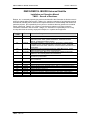
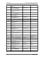
Record of Revisions
DMD15/DMD15L IBS/IDR Universal Satellite
Installation and Operation Manual
TM051 – Record of Revisions
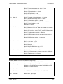
Radyne, Inc. is constantly improving its products and therefore the information in this document is
subject to change without prior notice. Radyne, Inc. makes no warranty of any kind with regard to
this material, Including but not limited to the implied warranties of merchantability and fitness for a
particular purpose. No responsibility for any errors or omissions that may pertain to the material
herein is assumed. Radyne, Inc. makes no commitment to update nor to keep current the
information contained in this document. Radyne, Inc. assumes no responsibility for use of any
circuitry other than the circuitry employed in Radyne, Inc. systems and equipment.
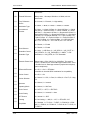
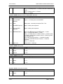
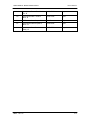
Revision
Level
Date
1.0
2.0
6-18-96
9-1-96
2.1
9-16-96
2.2
11-25-96
3.0
12-16-96
3.1
4-10-97
4.0
8-1-99
4.1
5.0
5.1
5.2
5.3
5.4
5.5
5.6
5.7
5.8
7-31-00
12-14-01
1-30-02
3-5-02
6-11-02
8-22-02
8-26-02
9-17-03
7-30-04
10-15-05
TM051 - Rev. 5.8
Reason for Change
Initial Release.
Expanded Drop and Insert Section, updated menu trees and descriptions,
added Strap Code Table, updated Fault Menus, added UIO Interface
Settings, updated Specifications Section.
Added DMD15/DMD15L Terminal Screens (Appendix C), added Modem
Loopback Figures, expanded Principles of Operation Section, added IBS
Conditions and Faults Table, added new Universal Interface Illustrations and
pinout tables.
Expanded Drop and Insert Data and figures, added BER Curves, added
additional Interface Pinout Tables and descriptions.
Added Reed-Solomon Menu Tree enhancements, added Clocking Data
Definitions, minor rearrangements and clarifications.
Added additional Reed-Solomon Data, additional UIM Data, and minor
corrections to pinout tables.
Added AUPC data, new Menu Screens, L-Band Data, ESC Audio Data and
minor corrections
Added AGC Output Data on Table 2-5.
Revised and reformatted entire Technical Manual.
Removed Ethernet Port section.
Revised Sections 4.3.2, Mod Data (menu), and 4.3.3, Demod Data (menu).
Revised Section 1.1.12.
Revised Sections 7.0 and 7.1.
Added Modem Status pinouts to Section 5.0.
Updated user interface, added reacquisition description, updated RLLP.
Revised RLLP.
Revised Sections 4.0 & 5.0
v
DMD15/DMD15L IBS/IDR Satellite Modem
vi
TM051 – Rev. 5.8
DMD15/DMD15L IBS/IDR Satellite Modem
Table of Contents
Table of Contents
Section 1 – Introduction
1.0 Description _____________________________________________________ 1-1
1.1 DMD15/DMD15L Available Options __________________________________ 1-1
1.1.1 Internal High Stability ____________________________________________ 1-1
1.1.2 Reed-Solomon Codec ___________________________________________ 1-1
1.1.3 Turbo Codec __________________________________________________ 1-2
1.1.4 Drop and Insert (D&I) ____________________________________________ 1-2
1.1.5 8PSK Modulation _______________________________________________ 1-2
1.1.6 OQPSK Modulation _____________________________________________ 1-2
1.1.7 16QAM Modulation______________________________________________ 1-2
1.1.8 Sequential Decoding ____________________________________________ 1-2
1.1.9 Earth Station-to-Earth Station (ES-ES) Communications ________________ 1-2
1.1.10 Analog AGC Voltage ___________________________________________ 1-2
1.1.11 Internal Engineering Service Channel (ESC)_________________________ 1-2
1.1.12 OM73 Compatible _____________________________________________ 1-2
1.1.13 Back Panel Options ____________________________________________ 1-3
1.1.14 Customized Options____________________________________________ 1-3
Section 2 – Installation
2.0 Installation Requirements __________________________________________ 2-1
2.1 Unpacking ______________________________________________________ 2-1
2.2 Removal and Assembly____________________________________________ 2-1
2.3 Mounting Considerations __________________________________________ 2-2
2.4 DMD15/DMD15L Initial Configuration Check ___________________________ 2-2
2.5 Modulator Checkout ______________________________________________ 2-3
2.5.1 Initial Power-Up ________________________________________________ 2-3
TM051 - Rev. 5.8
vii
Table of Contents
DMD15/DMD15L IBS/IDR Satellite Modem
Section 3 – Operation
3.0 Theory of Operation ______________________________________________ 3-1
3.1 DMD15/DMD15L Functional Block Diagram ____________________________ 3-1
3.2 Universal Interface Module (UIM) ____________________________________ 3-3
3.3 Synchronous Interface ____________________________________________ 3-4
3.4 G.703 Interface __________________________________________________ 3-4
3.5 Earth Station to Earth Station (ES-ES) Communications Port ______________ 3-5
(Async Port J9)______________________________________________________ 3-5
3.6 Terrestrial Loopback ______________________________________________ 3-5
3.7 Modem Status ___________________________________________________ 3-5
3.8 Baseband Processor Card _________________________________________ 3-8
3.8.1 Baseband Processing ___________________________________________ 3-8
3.8.2 Tx Baseband Processing _________________________________________ 3-8
3.8.3 Rx Baseband Processing_________________________________________ 3-9
3.8.4 Clock Selection ________________________________________________ 3-9
3.9 Monitor & Control (M&C) Subsystem _________________________________ 3-9
3.9.1 Asynchronous Serial Port #1 ______________________________________ 3-9
3.9.2 Serial Port #2 __________________________________________________ 3-9
3.9.3 Serial Port #3 __________________________________________________ 3-9
3.9.4 Front Panel Interface ___________________________________________ 3-10
3.9.5 Clock _______________________________________________________ 3-10
3.9.6 Watchdog Timer_______________________________________________ 3-10
3.9.7 Program Flash ROM ___________________________________________ 3-10
3.9.8 RAM ________________________________________________________ 3-10
3.9.9 Non-Volatile RAM______________________________________________ 3-10
3.10 Universal Modem ______________________________________________ 3-10
3.10.1 Modulator ___________________________________________________ 3-10
3.10.2 Demodulator_________________________________________________ 3-11
3.11 DMD15/DMD15L Clocking Options_________________________________ 3-11
3.11.1 SCTE: Serial Clock Transmit External _____________________________ 3-11
3.11.2 SCT: Serial Clock Transmit _____________________________________ 3-11
3.11.4 EXT EXC: External Clock_______________________________________ 3-11
3.11.5 BNC EXC: BNC External Clock __________________________________ 3-11
3.11.6 BAL EXC: Balanced External Clock_______________________________ 3-11
3.11.7 IDI: Insert Data In_____________________________________________ 3-12
viii
TM051 - Rev. 5.8
DMD15/DMD15L IBS/IDR Satellite Modem
Table of Contents
3.11.8 SCR: Serial Clock Receive _____________________________________ 3-12
3.11.9 EXT IF REF: External IF Reference_______________________________ 3-12
3.12 Transmit Timing _______________________________________________ 3-12
3.12.1 EXT CLK as TX Clock Source (RS-422 or V.35 Interface) _____________ 3-12
3.12.2 SCT or SCTE ________________________________________________ 3-12
3.12.3 G.703 Interface ______________________________________________ 3-12
3.13 Receive Timing ________________________________________________ 3-12
3.14 Loop Timing __________________________________________________ 3-13
3.14.1 Transmit (RS-422 or V.35 Interface) ______________________________ 3-13
3.14.2 G.703 Interface or Asymmetrical Data Rates _______________________ 3-13
3.14.3 Receive ____________________________________________________ 3-13
3.15 Drop and Insert (D&I) ___________________________________________ 3-13
3.15.1 Drop Only ___________________________________________________ 3-15
3.15.2 Insert Only __________________________________________________ 3-15
3.16 Mode Selection ________________________________________________ 3-16
3.16.1 PCM-30 ____________________________________________________ 3-16
3.16.2 PCM-30C ___________________________________________________ 3-16
3.16.3 PCM-31 ____________________________________________________ 3-16
3.16.4 PCM-31C ___________________________________________________ 3-17
3.16.5 T1-D4/T1-D4-S_______________________________________________ 3-17
3.16.6 T1-ESF/ T1-ESF-S____________________________________________ 3-17
3.16.7 SLC-96 _____________________________________________________ 3-17
3.17 Multidestinational Systems _______________________________________ 3-17
3.17 Drop and Insert Mapping_________________________________________ 3-18
3.18 Reed-Solomon Codec (Refer to Figures 3-14, 3-15, and Table 3-1) _______ 3-20
3.18.1 Operation in the DMD15/DMD15L ________________________________ 3-20
3.18.2 Reed-Solomon Code Rate ______________________________________ 3-20
3.18.3 Interleaving__________________________________________________ 3-20
3.19 DMD15 Automatic Uplink Power Control (AUPC Operation) _____________ 3-22
3.20 DMD15 Asynchronous Overhead Operation__________________________ 3-24
3.20.1 Asynchronous Framing/Multiplexer Capability _______________________ 3-24
3.21 Standard IBS Mode_____________________________________________ 3-26
3.22 Asynchronous Multiplexer Mode __________________________________ 3-26
3.23 ESC Backward Alarms __________________________________________ 3-26
3.23.1 To Disable the ESC Backward Alarms_____________________________ 3-27
TM051 - Rev. 5.8
ix
Table of Contents
DMD15/DMD15L IBS/IDR Satellite Modem
3.24 Reacquisition__________________________________________________ 3-27
Section 4 – User Interfaces
4.0 User Interfaces __________________________________________________ 4-1
4.1 Front Panel User Interface _________________________________________ 4-1
4.1.1 LCD Front Panel Display _________________________________________ 4-2
4.1.2 Cursor Control Arrow Keys _______________________________________ 4-2
4.1.3 Numeric Keypad________________________________________________ 4-2
4.1.4 Front Panel LED Indicators _______________________________________ 4-3
4.2 Parameter Setup _________________________________________________ 4-3
4.3 Front Panel Control Screen Menus___________________________________ 4-4
4.3.1 Main Menus ___________________________________________________ 4-4
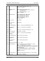
4.3.2 Modulator Menu Options and Parameters ____________________________ 4-4
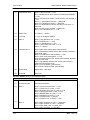
4.3.3 Demodulator Menu Options and Parameters__________________________ 4-8
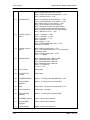
4.3.4 Interface Menu Options and Parameters ____________________________ 4-11
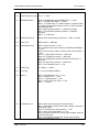
4.3.5 AUPC Menu Options and Parameters ______________________________ 4-14
4.3.6 Monitor Menu Options and Parameters _____________________________ 4-16
4.3.7 Alarms Menu Options and Parameters _____________________________ 4-17
4.3.8 System Menu Options and Parameters _____________________________ 4-24
4.3.9 Test Menu Options and Parameters _______________________________ 4-25
4.4 DMD15/DMD15L Strap Codes _____________________________________ 4-26
4.5 Sample DMD15/DMD15L Applications _______________________________ 4-30
4.5.1 Operational Case Examples _____________________________________ 4-31
4.6 Configuring the DMD15/DMD15L for Drop and Insert ___________________ 4-34
4.6.1 Data Rate ____________________________________________________ 4-34
4.6.2 Operational Mode______________________________________________ 4-35
4.6.3 Terrestrial Framing - Drop Mode/Insert Mode ________________________ 4-35
4.6.3.1 Insert Terrestrial Frame Source _________________________________ 4-35
4.6.4 D&I Sample Configurations and D&I Clock Setup Options ______________ 4-36
4.7 D&I Maps and Map Editing ________________________________________ 4-40
4.8 Terminal Mode Control ___________________________________________ 4-43
4.8.1 Modem Terminal Mode Control ___________________________________ 4-43
4.8.2 Modem Setup for Terminal Mode__________________________________ 4-43
x
TM051 - Rev. 5.8
DMD15/DMD15L IBS/IDR Satellite Modem
Table of Contents
Section 5 – Electrical Interfaces
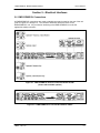
5.0 DMD15/DMD15L Connections ______________________________________ 5-1
5.1 Power Inputs ____________________________________________________ 5-2
5.1.1 AC Power Input Module __________________________________________ 5-2
5.1.2 DC Power Input Module __________________________________________ 5-2
5.2 TX (J1) ________________________________________________________ 5-3
5.3 RX (J2) ________________________________________________________ 5-3
5.4 SD (J3) ________________________________________________________ 5-3
5.5 DDO (J4) _______________________________________________________ 5-3
5.6 IDI EXC (J5) ____________________________________________________ 5-3
5.7 EXT CLK (J5) – Synchronous Interface Only ___________________________ 5-3
5.8 RD (J6) ________________________________________________________ 5-3
5.9 G.703 (J7) ______________________________________________________ 5-3
5.10 SYNC DATA (J8) _______________________________________________ 5-4
5.11 ASYNC (J9)____________________________________________________ 5-5
5.11 STATUS (J11)__________________________________________________ 5-6
5.13 TERMINAL (J12) ________________________________________________ 5-7
5.14 REMOTE (J13) _________________________________________________ 5-7
5.15 ESC 8K DATA (J15) _____________________________________________ 5-8
5.16 ESC VOICE (J16) _______________________________________________ 5-9
5.17 ESC ALARMS (J17) _____________________________________________ 5-9
5.18 SWITCH (J18)_________________________________________________ 5-10
Section 6 – Maintenance
6.0 Periodic Maintenance _____________________________________________ 6-1
6.1 Troubleshooting _________________________________________________ 6-1
6.2 DMD15/DMD15L Fault Philosophy ___________________________________ 6-1
6.2.1 Alarm Masks __________________________________________________ 6-2
6.2.2 Active Alarms __________________________________________________ 6-2
6.2.2.1 Major Alarms _________________________________________________ 6-2
6.2.2.2 Minor Alarms _________________________________________________ 6-2
6.2.2.3 Latched Alarms _______________________________________________ 6-2
6.3 DMD15/DMD15L Fault Tree Matrices _________________________________ 6-2
6.3.1 Interpreting the Matrices _________________________________________ 6-4
6.3.2 IBS Fault Conditions and Actions___________________________________ 6-4
TM051 - Rev. 5.8
xi
Table of Contents
DMD15/DMD15L IBS/IDR Satellite Modem
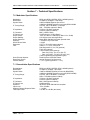
Section 7 – Technical Specifications
7.0 Modulator Specifications ___________________________________________ 7-1
7.1 Demodulator Specifications ________________________________________ 7-1
7.2 Plesiochronous Buffer _____________________________________________ 7-2
7.3 Monitor and Control_______________________________________________ 7-2
7.4 DMD15/DMD15L Drop and Insert (Optional) ___________________________ 7-2
7.5 Terrestrial Interfaces ______________________________________________ 7-3
7.6 Universal Interface _______________________________________________ 7-3
7.7 Environmental ___________________________________________________ 7-3
7.8 Physical ________________________________________________________ 7-3
7.9 DMD15 Data Rate Limits __________________________________________ 7-4
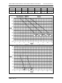
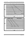
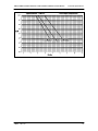
7.10 DMD15 BER Specifications________________________________________ 7-5
Section 8 – Appendices
Appendix A – Reed-Solomon Codes _____________________________________ A-1
Glossary __________________________________________________________ G-1
xii
TM051 - Rev. 5.8
DMD15/DMD15L IBS/IDR Satellite Modem
Introduction
Section 1 – Introduction
1.0 Description
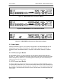
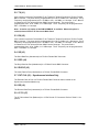
The Radyn, Inc. DMD15/DMD15L Satellite Modem (Figure 1-1) offers the best features of a
sophisticated programmable IBS/IDR and Closed Network Modem, at an affordable price.
This versatile equipment package combines unsurpassed performance with numerous userfriendly Front Panel Programmable Functions. The DMD15/DMD15L provides selectable
functions for different services: Intelsat IDR and IBS, as well as closed networks. All of the
configuration and Monitor and Control (M&C) Functions are available at the Front Panel.
Operating parameters, such as variable data rates, FEC Code Rate, modulation type, IF
frequencies, IBS/IDR Framing and interface type can be readily set and changed at the Front
Panel by earth station operations personnel. Additionally, all functions can be accessed with a
terminal or personal computer via a serial link for complete remote monitoring and control
capability.
The DMD15/DMD15L operates at all standard IBS and IDR Data Rates up to 8.448 Mbps.
Selection of any data rate is provided over the range of 9.6 Kbps to 10 Mbps in 1 bps steps.
For applications requiring system redundancy, the DMD15/DMD15L Modem may be used with the
Radyne , Inc. RCS11 1:1 Redundancy Switch or the RCS20 M:N (N < 9) Redundancy Switch. An
optional Internal Engineering Service Channel Unit is available to provide voice, data, and alarms
for Intelsat IDR applications.
A full range of Industry Standard Interfaces is available for the DMD15/DMD15L. Interface types
are selectable from V.35, RS-232, RS-422/449 and ITU G.703.
Figure 1-1. DMD15/DMD15L Universal Satellite Modem Front Panel
1.1 DMD15/DMD15L Available Options
A wide range of options is available for the DMD15/DMD15L Satellite Modem.
1.1.1 Internal High Stability
-7
The DMD15/DMD15L can be equipped with a 1x10 or better Stability Frequency Reference as
an add-on enhancement.
1.1.2 Reed-Solomon Codec
The DMD15/DMD15L can be equipped with a Reed-Solomon (R-S) Outer Codec with an
interleaver as an optional add-on enhancement. The encoder and decoder are completely
independent and meet the IESS-308/309/310 specification. Once prepped, this option can be
installed in the field by installing five ICs into existing sockets. The DMD15/DMD15L must be
prepped for this option.
Note: Custom Reed-Solomon codes are also available.
TM051 - Rev. 5.8
1-1
Introduction
DMD15/DMD15L IBS/IDR Satellite Modem
1.1.3 Turbo Codec
The DMD15/DMD15L can be equipped with an optional Turbo Codec Outer Code. This option
must be installed at the factory.
1.1.4 Drop and Insert (D&I)
The DMD15/DMD15L can be equipped with a D&I Interface as an add-on enhancement. This
option can be added in the field by installing one IC into an existing socket. The D&I Functions
are completely independent and can be programmed for n x 64 blocks for either a T1 or E1 Data
Stream.
1.1.5 8PSK Modulation
The DMD15/DMD15L can be equipped with 8PSK Modulation/Demodulation capability as an addon option. The 8PSK Option can be added by installing 2 ICs into existing sockets.
1.1.6 OQPSK Modulation
The DMD15/DMD15L can be equipped with an OQPSK modulation/demodulation capability as an
add-on option. The option can be added in the field by installing one IC into an existing socket.
1.1.7 16QAM Modulation
The DMD15/DMD15L can be equipped with a 16QAM Modulation/Demodulation capability as an
add-on option. The 16QAM option can be added by installing 2 ICs into existing sockets.
1.1.8 Sequential Decoding
The DMD15/DMD15L can be equipped with a sequential decoding option that can be installed as
an add-on option. The DMD15/DMD15L must be prepped for this option in the factory. Once
prepped, the option can be added by installing 3 ICs into existing sockets. Sequential
Encoding/Decoding can operate with 1/2, 3/4, and 7/8 Rates, up to data rates of 2.048 Mbps.
1.1.9 Earth Station-to-Earth Station (ES-ES) Communications
The DMD15/DMD15L can be equipped with an asynchronous overhead channel capability as an
add-on option. The option can be added in the field by installing 2 ICs into existing sockets. The
overhead channel is proportional to the data rate (2,400 baud per 64 KB) up to a maximum of
19.2 Kbaud.
1.1.10 Analog AGC Voltage
The DMD15/DMD15L can be equipped at the factory to produce an analog voltage equivalent to
its AGC for use in antenna controllers.
1.1.11 Internal Engineering Service Channel (ESC)
The DMD15/DMD15L can be equipped with an internal ESC. This unit is a card on the Universal
Interface Module (UIM). The DMD15/DMD15L can be updated with an ESC capable UIM in the
field with no other changes required.
1.1.12 OM73 Compatible
1-2
TM051 – Rev. 5.8
DMD15/DMD15L IBS/IDR Satellite Modem
Introduction
The DMD15/DMD15L can be equipped with an optional OM73 scrambler at the customer’s
request. This option must be prepped at the factory. Once installed, selection of the OM73
Scrambler/Descrambler will automatically invert the baseband data on the Modulator/Demodulator
respectively. This configuration is required to run compatible with the OM73 Modem.
1.1.13 Back Panel Options
The DMD15/DMD15L has several optional Interface Modules available (refer to Figures 5-1
through 5-5). These include:
Universal Interface Module w/ ESC
G.703 Interface Module w/ESC
G.703 Interface Module
Universal Interface Module
Synchronous Interface Module
These Interface Modules are available with AC or DC Power Input Modules and the following
Transmit and Receive schemes.
IF Transmit and Receive
L-Band Transmit and Receive
IF Transmit, L-Band Receive
IF Receive Only
L-Band Receive Only
1.1.14 Customized Options
The DMD15/DMD15L may be customized for specific customer requirements. Most modifications
or customization can be accomplished by means of firmware/software modifications.
The following are examples of the types of customization available to the user:
Customized Data Rates.
Customized Scrambler/Descramblers.
Customized Overhead Framing Structures.
Customized Modulation Formats.
Customized Uses for the Earth Station-to-Earth Station (ES-ES) Overhead Channel.
Contact the Radyne , Inc. Customer Service or Sales Department at (602) 437-9620 for all
requests.
TM051 - Rev. 5.8
1-3
DMD15/DMD15L IBS/IDR Satellite Modem
Installation
Section 2 – Installation
2.0 Installation Requirements
The DMD15/DMD15L Modem is designed to be installed within any standard 19-inch wide
equipment cabinet or rack, and requires one rack unit (RU) of mounting space (1.75 inches)
vertically and 21 inches of depth. Including cabling, a minimum of 23 inches of rack depth is
required. The rear panel of the DMD15/DMD15L is designed to have power enter from the right
and IF Cabling enter from the left when viewed from the rear of the modem. Data and control
cabling can enter from either side although they are closer to the right. The unit can be placed on
a table or suitable surface if required.
There are no user-serviceable parts or configuration settings located inside
the DMD15/DMD15L Chassis. There is a potential shock hazard internally at
the power supply module. DO NOT open the DMD15/DMD15L Chassis
under any circumstances.
Before initially applying power to the unit, it is a good idea to disconnect
the transmit output from the operating ground station equipment. This is
especially true if the current DMD15/DMD15L configuration settings are
unknown, where incorrect settings could disrupt existing communications
traffic.
2.1 Unpacking
The DMD15/DMD15L Modem was carefully packaged to avoid damage and should arrive
complete with the following items for proper installation:
1.
2.
3.
DMD15/DMD15L Modem Unit.
Power Cord, 6-foot with applicable AC Connector.
Installation and Operation Manual.
2.2 Removal and Assembly
Carefully unpack the unit and ensure that all of the above items are in the carton. If the Prime AC
power available at the installation site requires a different Power Cord/AC Connector, then
arrangements to receive the proper device will be necessary before proceeding with the
installation.
The DMD15/DMD15L Modem Unit is shipped fully assembled and does not require removal of the
covers for any purpose in installation. The only replaceable assembly in the unit is the Universal
Interface Module (UIM).
TM051 - Rev. 5.8
2-1
Installation
DMD15/DMD15L IBS/IDR Satellite Modem
Always ensure that power is removed from the DMD15/DMD15L before
removing or installing a UIM. Failure to do so may cause damage to the
equipment.
Should the Power Cable/AC Connector be of the wrong type for the installation, either the cable or
the power connector end should be replaced. The power supply itself is designed for universal
application using from 100 to 240 VAC, 50 to 60 Hz, 1.0 A.
2.3 Mounting Considerations
When mounted in an equipment rack, adequate ventilation must be provided. The ambient
temperature in the rack should preferably be between 10° and 35° C, and held constant for best
equipment operation. The air available to the rack should be clean and relatively dry. The
modem units may be stacked one on top of the other to a maximum of 10 consecutive units
before providing one RU of space for airflow. Modem units should not be placed immediately
above a high heat or EMF Generator to ensure the output signal integrity and proper receive
operation.
Do not mount the DMD15/DMD15L in an unprotected outdoor location where there is direct
contact with rain, snow, wind or sun. The modem is designed for indoor applications only. The
only tools required for rack mounting the DMD15/DMD15L is a set of four rack-mounting screws
and the appropriate screwdriver. Rack mounting brackets are an integral part of the cast front
bezel of the unit and are not removable.
2.4 DMD15/DMD15L Initial Configuration Check
The DMD15/DMD15L is shipped from the factory with preset factory defaults. Upon initial powerup, a user check should be performed to verify the shipped modem configuration. Refer to
Section 4, User Interfaces to locate and verify that the following configuration settings are correct:
The DMD15/DMD15L Interface Type (V.35, RS-422, RS-232, G.703, etc.)
MUST be selected from the Front Panel BEFORE the mating connectors are
installed. Failure to do so may cause damage to the Universal Interface
Module. Power up the DMD15/DMD15L, select the appropriate interface
type, and then install the mating connectors.
Note: Transmit (Tx) and Receive (Rx) Interface types are dependent upon the customer’s
order.
2-2
TM051 – Rev. 5.8
DMD15/DMD15L IBS/IDR Satellite Modem
Installation
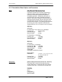
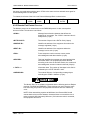
Standard DMD15/DMD15L Factory Configuration Settings
Modulator:
Data Rate:
Mode:
Forward Error Correction:
Modulation:
Frequency:
2.048 Mbps
Closed Network
1/2 Rate Viterbi
QPSK
70.000000 MHz
Note: The above modem configuration can be set by implementing Strap Code 26.
Refer to Table 3-1 for an explanation and tabular listing of available Strap Codes.
Modulator Output Power:
-20 dBm
Demodulator:
Data Rate:
Mode:
Forward Error Correction:
Frequency:
2.048 Mbps
Closed Network
1/2 Rate Viterbi
70.000000 MHz
To lock up the modem, enter ‘IF Loopback Enable’ under the Test menu, or connect a Loopback
Cable from J1 to J2 on the rear panel of the modem.
2.5 Modulator Checkout
The following descriptions assume that the DMD15/DMD15L is installed in a suitable location with
prime AC power and supporting equipment available.
2.5.1 Initial Power-Up
Before initial power up of the DMD15/DMD15L, it is a good idea to
disconnect the transmit output from the operating ground station
equipment. This is especially true if the current Modulator Configuration
Settings are unknown, where incorrect settings could disrupt the existing
communications traffic. New units from the factory are normally shipped in
a default configuration which includes setting the transmit carrier off.
Turn on the unit by placing the Rear Panel Switch (located above the power entry connector) to
the ‘ON’ position. Upon initial and subsequent power-ups, the DMD15/DMD15L Microprocessor
will test itself and several of its components before beginning its Main Monitor/Control Program.
These power-up diagnostics show no results if successful. If a failure is detected, the Fault LED
will illuminate.
TM051 - Rev. 5.8
2-3
Installation
DMD15/DMD15L IBS/IDR Satellite Modem
The initial field checkout of the modem can be accomplished from the Front Panel or in the
Terminal Mode. The Terminal Mode has the advantage of providing full screen access to all of
the modem’s parameters, but requires a separate terminal or computer running a Terminal
Program. The unit is placed into terminal mode by setting two options via the Front Panel. The
two options are the Term Baud and Emulation settings found under the System M&C Submenus.
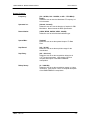
Terminal Setup:
Baud Rate:
Data Bits:
Parity:
Stop Bits:
2-4
19.2 K (Can be changed via Front Panel)
8
No Parity (Fixed)
1 Stop Bit
TM051 – Rev. 5.8
DMD15/DMD15L IBS/IDR Satellite Modem
Operation
Section 3 – Operation
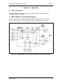
3.0 Theory of Operation
The DMD15/DMD15L is designed in three major sections: Universal Interface, Baseband
Processing, and Universal Modem.
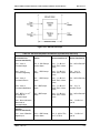
3.1 DMD15/DMD15L Functional Block Diagram
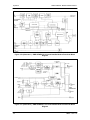
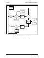
Figures 3-1a through 3-1c represent the DMD15/DMD15L Functional Blocks. The modem is
shown in a typical application with customer data, Tx/Rx RF equipment and an antenna.
Figure 3-1a. DMD15/DMD15L Universal Satellite Modem Functional Block Diagram
TM051 - Rev. 5.8
3-1
Operation
DMD15/DMD15L IBS/IDR Satellite Modem
Figure 3-1b (Alternate 1). DMD15/DMD15L Universal Satellite Modem Functional Block
Diagram
Figure 3-1c (Alternate 2). DMD15/DMD15L Universal Satellite Modem Functional Block
Diagram
3-2
TM051 – Rev. 5.8
DMD15/DMD15L IBS/IDR Satellite Modem
Operation
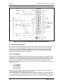
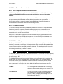
3.2 Universal Interface Module (UIM)
The Universal Interface Module (UIM) is a field-replaceable module that plugs into the rear of the
DMD15/DMD15L. The UIM provides the interconnection points (J3 - J8) for Terrestrial Data and
Clock to the Modem. The UIM also contains a Connection Port for an Asynchronous Data
Channel (J9) for use in Earth Station-to-Earth Station (ES-ES) communications. Additionally, the
UIM provides connection points (J11) for Form-C modem Status Relays. An illustration of two
versions of the UIM is shown in Figure 3-2, and Functional Block Diagrams are shown in
Figure 3-3.
Figure 3-2. Universal Interface Modules (UIM) Dip Switch Settings
TM051 - Rev. 5.8
3-3
Operation
DMD15/DMD15L IBS/IDR Satellite Modem
Figure 3-3. Universal Interface Modules (UIM) Functional Block Diagram
3.3 Synchronous Interface
Synchronous Tx Data and Clock enters the UIM and is routed to either the RS-422, RS-232, or
V.35 Receiver as the selected M&C Processor. The signals are then converted to an RS-422
balanced format and sent to the Baseband (BB) Processor Card. Receive Data from the BB
Processor Card undergoes the reverse process where it is converted from RS-422 Balanced
format and routed to the RS-422 or V.35 Drivers.
3.4 G.703 Interface
Either Balanced or Unbalanced G.703 Data is routed from the ‘Send Data In’ Connections to the
G.703 Receiver. The G.703 Receiver recovers a clock from the data stream, converts the clock
and data to an RS-422 balanced format, and routes the clock and data to the BB Processor. The
reverse process is performed on the Receive Data Stream where the G.703 Data exits the
modem at the ‘Receive Data Out’ Connection. The G.703 Interface is designed to operate at the
following data rates:
T1 (1.544 Mbps)
E1 (2.048 Mbps)
T2 (6.312 Mbps)
E2 (8.448 Mbps)
Additionally, the line code is selected when the interface type is selected with the exception that
T1 may use B8ZS or AMI as selected at the Front Panel.
The G.703 Interface also contains two additional ports that can operate at T1 or E1 that provides
a four port D&I Interface. The ‘Drop Data Out’ Port provides an unaltered Send Data Output that
can be used for daisy chaining additional systems. On the receive side, a T1 or E1 Data Stream
3-4
TM051 – Rev. 5.8
DMD15/DMD15L IBS/IDR Satellite Modem
Operation
can be connected to the ‘Insert Data In’ Port where received data will overwrite ‘dropped on’ the
T1/E1 Data Stream. The modified T1/E1 Data Stream will then exit the modem out of the
‘Receive Data Out’ Port.
3.5 Earth Station to Earth Station (ES-ES) Communications Port
(Async Port J9)
The UIM contains a selectable RS-232, or RS-485 Asynchronous Communications Port for EarthStation-to-Earth-Station Communications. The data is routed from the 9-Pin “D” Connector J9 to
one of the M&C Processor UARTS on the Baseband Processor Card. The baud rate and protocol
can be selected from the Front Panel.
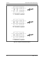
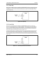
3.6 Terrestrial Loopback
The UIM also provides for terrestrial loopback. For Tx Terr Loopback, Tx Data, after passing
through the Line Interface is looped back to the Rx Data line drivers. For RX Terr Loopback, the
Receive Data from the satellite is looped back for retransmission to the satellite providing a far
end loopback. Tx/Rx Loopback provides both loopbacks simultaneously. Refer to Figures 3-4
through 3-6 for loopback functional block diagrams.
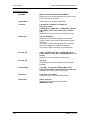
3.7 Modem Status
The UIM provides several status indications, which are controlled by the M&C Processor.
Form-C Contacts:
The UIM provides three Form-C Relays under processor control that appear at J11.
Mod Fault:
De-energized when any transmit side fault is detected.
Demod Fault:
De-energized when any receive side fault is detected.
Common Fault:
De-energized when any fault that is not explicitly a Tx or
Rx Fault such as an M&C or Power Supply Fault.
Open Collector Faults:
The UIM provides two Open Collector Faults that appear at Pins 28 & 10 on J8.
Mod Fault:
Will sink up to 20 ma (maximum) until a transmit or
common fault is detected. Will not sink current if a fault
is detected.
Demod Fault:
Will sink up to 20 ma (maximum) until a receive or
common fault is detected. Will not sink current if a fault
is detected.
The open collector faults are intended for use in redundancy switch applications in order to
provide quick status indications.
TM051 - Rev. 5.8
3-5
Operation
DMD15/DMD15L IBS/IDR Satellite Modem
Figure 3-4. Loopback Functional Block Diagram
3-6
TM051 – Rev. 5.8
DMD15/DMD15L IBS/IDR Satellite Modem
Operation
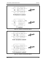
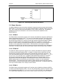
Figure 3-5. Loopback Functional Block Diagram
Figure 3-6. Loopback Functional Block Diagram
TM051 - Rev. 5.8
3-7
Operation
DMD15/DMD15L IBS/IDR Satellite Modem
3.8 Baseband Processor Card
The Baseband Processor Card (BB Card) contains two major subsystems⎯the Baseband
Processing System and the Monitor and Control Subsystem.
3.8.1 Baseband Processing
The Baseband Processor performs all of the functions required for an IBS/IDR Framing Unit, a
Reed-Solomon Codec, an E1/T1 Drop and Insert System and a Turbo Codec. In addition, the
Baseband Processing Section provides for Transmit clock selection and rate adaptation as well as
a rate adapter and Plesiochronous/Doppler (PD) Buffer in the receive direction. A multiplexer is
also provided for the SCT Clock Source for Loop Timing Applications. The transmit and receive
paths may be configured independently under processor control.
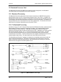
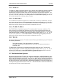
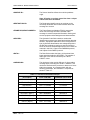
3.8.2 Tx Baseband Processing
As shown in Figure 3-7, the Tx Data and Clock enters the Baseband Processor, passes through a
Rate Adapting FIFO and enters the Framer/Drop Processor. In Closed-Net Mode, the data
passes through the framer unaltered. In IDR, IBS, and D&I Modes, the framer adds the
appropriate framing and ESC as defined in IESS-308 and 309. In D&I Mode, the framer acquires
the terrestrial framing structure, E1 or T1, and synchronizes the Drop Processor. The Drop
Processor extracts the desired time slots from the terrestrial data stream and feeds these
channels back to the framer. The framer then places the ‘dropped’ terrestrial time slots into the
desired satellite channel slots. The data is then sent to the Reed-Solomon Encoder.
The Reed-Solomon Encoder, if engaged, is designed as an installable option that encodes the
data into Reed-Solomon Blocks. The blocks are interleaved and synchronized to the frame
pattern as defined in IESS-308 and IESS-309. After Reed-Solomon Encoding, the composite
data and clock are applied to the BB Loopback Circuit.
Figure 3-7. DMD15/DMD15L Clock Logic
3-8
TM051 – Rev. 5.8
DMD15/DMD15L IBS/IDR Satellite Modem
Operation
3.8.3 Rx Baseband Processing
The Receive Processor performs the inverse function of the Tx Processor. Data received from
the satellite passes through the BB Loopback Circuit to the Reed-Solomon Decoder to the
Deframer. The Deframer acquires the IBS/IDR frame, synchronizes the Reed-Solomon Decoder
and extracts the received data and overhead from the frame structure, placing the data into the
PD Buffer, sending the overhead data to the UIM. In Closed-Net Mode, the data is extracted from
the buffer and is sent to the UIM. Backward Alarm indications are sent to the M&C Subsystem.
In Drop and Insert Mode, the Insert Processor synchronizes to the incoming terrestrial T1/E1 Data
Stream, extracts satellite channels from the PD Buffer, and then inserts them into the desired
terrestrial time slots in the T1/E1 Data Stream.
3.8.4 Clock Selection
Both the Tx Clock and the Buffer Clock source may be independently locked to one of the
following:
SCT (Internal Oscillator)
SCTE (External Tx Terrestrial Clock)
EXC clock (External Clock Source)
Rx Satellite Clock (Loop Timing)
Additionally, for loop timing applications the SCT Clock Source can be selected to be Rx Satellite
Clock.
3.9 Monitor & Control (M&C) Subsystem
Also contained on the BB Card is the M&C Subsystem. The M&C contains a high-performance
Motorola 68302 Microprocessor and is responsible for overall command and control of modem
functions. The M&C is constantly monitoring all subsystems of the modem by performing a
periodic poll routine and configures the modem by responding to commands input to the system.
During each poll cycle, the status of each of the subsystems is collected and reported to each of
the external ports and Front Panel. Performance statistics such as Eb/No, buffer fill %, etc. are
compiled. If faults are detected, the M&C will take appropriate actions to minimize the effect of
such faults on the system (Refer to the Fault Matrices in the Section 6 (Maintenance) of this
manual).
The M&C subsystem contains the following features:
3.9.1 Asynchronous Serial Port #1
This port is dedicated to the Terminal Program. With this program, all features of the modem may
be controlled and monitored by any common terminal connected to the Terminal Port.
3.9.2 Serial Port #2
This port is dedicated to the Modem Remote Port. This port may be configured to support a
number of synchronous or asynchronous protocols such as HDLC, and RS-485. This port is
intended for use in computer-based remote M&C. All functions of the modem may be monitored
and controlled from this port.
3.9.3 Serial Port #3
This port is dedicated for ES-ES Communications. The port may be configured for a number of
communications protocols. Overhead data to/from the UIM is routed to/from the framer/deframer.
TM051 - Rev. 5.8
3-9
Operation
DMD15/DMD15L IBS/IDR Satellite Modem
3.9.4 Front Panel Interface
The M&C operates the Front Panel, which includes a 2 x 12 backlit LCD, Indicator LEDs, and a
Numeric Keypad.
3.9.5 Clock
The time and date is kept in order to ‘time-tag’ system events.
3.9.6 Watchdog Timer
The Watchdog Timer monitors the health of the M&C Subsystem.
3.9.7 Program Flash ROM
The 512K of reprogrammable program ROM (expandable to 1 MB) is available to the M&C.
3.9.8 RAM
128K RAM (expandable to 512K)
3.9.9 Non-Volatile RAM
8K of Non-Volatile RAM (expandable to 32K) is provided in order to hold the modems current
configuration. In the case of power interruption, the M&C will reconfigure the modem identically to
the state before power was lost.
3.10 Universal Modem
The Universal Modem (UM) Card contains a complete variable rate modulator/demodulator
intended for satellite communications. The UM utilizes the latest digital technology for high
reliability and versatility. The modulator and demodulator sections may be configured
independently under processor control. The UM includes a duaL-Band 70/140 MHz IF, QAM
Modulator/Phase Lock Receiver, Convolutional Encoder/Viterbi Decoder, sequential decoding
option, Differential Encoder/Decoder, and a V.35 Scrambler/Descrambler.
3.10.1 Modulator
Processed baseband data ready for transmission enters the modulator and undergoes, if the
functions have been enabled, V.35 Scrambling and Differential Encoding. The data then
undergoes convolutional encoding and is fed to the Dual Variable Interpolating FIR Filter. The FIR
Filter shapes the data waveform to a predefined spectral mask and vectorizes the data for
mapping into a PSK Constellation. The data is then converted to an analog waveform and is
vector modulated onto an RF Carrier produced from the Transmit IF Synthesizer Circuitry. The
final output is then fed to the IF Loopback Circuitry where under microprocessor control the
Transmit Signal may be routed to the demodulator. Due to its nearly complete digital
implementation, the modulator is capable of performing virtually any modulation format, and can
produce almost any desired spectral mask. The modulator also houses the SCT and Reference
Oscillators. The Reference Oscillator provides the frequency standard for both the modulator and
demodulator. An external reference may also be selected. In this case, the Reference Oscillator
is locked to the external reference.
3-10
TM051 – Rev. 5.8
DMD15/DMD15L IBS/IDR Satellite Modem
Operation
3.10.2 Demodulator
The demodulator performs a complete digital implementation of a Variable-Rate Phase-Lock
Satellite Receiver utilizing state-of-the-art digital signal processing techniques. The demodulator
is capable of receiving nearly any modulation format. Signals enter the demodulator, are
converted to baseband, split into ‘I’ In-Phase and ‘Q’ Quadrature Channels and digitized. The
digitized I and Q Channels are then applied to a decimating FIR Matched Filter. After filtering, the
signal is demodulated using a Costas Loop for recovery of the carrier and a clock recovery loop
for recovery of bit timing. The demodulated data is then fed to a 1650 Viterbi Decoder, or
Sequential Decoder if the option is installed. After decoding, the data is differentially decoded and
descrambled.
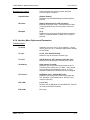
3.11 DMD15/DMD15L Clocking Options
The following paragraphs define the types of clocking options available to the user at the Front
Panel of the DMD15/DMD15L:
3.11.1 SCTE: Serial Clock Transmit External
This clock is the Transmit Terrestrial Clock associated with the interface. With the G.703
Interface selected, SCTE is the clock that is recovered from the G.703 data stream. SCTE is
sometimes referred to as Tx Terrestrial Timing and for Synchronous Interfaces such as RS-422,
SCTE is sometimes referred to as TT (Terminal Timing).
3.11.2 SCT: Serial Clock Transmit
This clock is an internally generated clock that is output from the modem. The clock is generally
used by the Terrestrial Terminal equipment for clocking the transmit data. The frequency of the
clock is set the same as the Transmit Terrestrial Clock rate if internal is selected, or is the receive
clock from the Demodulator if SCR is selected. SCT is sometimes referred to as Internal Timing
or ST (Send Timing).
3.11.4 EXT EXC: External Clock
This is an independent clock source. This clock is most often used if there is a station master
clock. The EXT EXC can be selected, in the Interface/General Menu, to be balanced, bnc exc,
sys rcs10, or IDI. IDI is used ONLY for D&I cases where external framing is selected. In this
case the EXT EXC must be set to IDI where the Receive Buffer Clock is derived from the external
Receive T1 or E1 Trunk.
3.11.5 BNC EXC: BNC External Clock
Unbalanced external clock input into BNC Connector J5.
Clock specification:
Frequency:
Level:
1 MHz – 10 MHz in 40 kHz steps
0.5 Vp-p – 5 Vp-p
3.11.6 BAL EXC: Balanced External Clock
This clock is input into J8-15-33, J7-7-8, or J18-13-47; all connectors are wired together for this
clock and so only one connector pair should be driven at one time. The clock must meet RS-422
levels.
TM051 - Rev. 5.8
3-11
Operation
DMD15/DMD15L IBS/IDR Satellite Modem
3.11.7 IDI: Insert Data In
This clock source is only used as an external frame source selected in D&I Mode. If External
Frame Source is selected, then IDI must be selected for the buffer clock. For this case, a
Receive T1/E1 Trunk is input into J5 and a buffer clock is derived.
3.11.8 SCR: Serial Clock Receive
This Receive Clock is recovered from the satellite’s receive signal from the satellite. SCR is
sometimes referred to as Receive Clock, Satellite Clock, or as RT (Receive Timing).
3.11.9 EXT IF REF: External IF Reference
This is not actually a clock, but does have some clocking implications. When the external
reference is used, the master oscillator within the DMD15/DMD15L is locked to the external
reference, and the internal accuracy and stability of the DMD15/DMD15L assumes that of the
External Reference. Therefore, not only are the transmit and receive frequencies of the
DMD15/DMD15L locked to the external reference, but the modem’s internal SCT Oscillator is
locked to the external reference as well.
3.12 Transmit Timing
As shown in Figure 3-7, Transmit Terrestrial Data enters the modem and is clocked into a Dejitter
FIFO. Data is clocked out of the FIFO by the Modulator Clock. The Modulator Clock and PhaseLocked Loop (PLL), in conjunction with the Dejitter FIFO, reduces the input jitter. Jitter reduction
exceeds the jitter transfer specified in CCITT G.821.
3.12.1 EXT CLK as TX Clock Source (RS-422 or V.35 Interface)
Data must be clocked into the modem by either the SCTE or SCT Source. If EXT CLK is selected
as the Tx Clock Source, then SCTE must be supplied to the modem. The output of the dejitter
buffer will be clocked with EXT CLK. This case should only be used if SCTE has excessive jitter
and will degrade link performance.
3.12.2 SCT or SCTE
If SCT is selected, then only data that is synchronous to the SCT Clock is required to be supplied
to the modem. It is intended for the terminal equipment to use the SCT as its clock source. The
Autophase Circuit will automatically ensure that the data is clocked correctly into the modem.
Therefore, a return clock is not necessary. The Clock Polarity should be set to AUTO.
If SCTE is selected, then SCTE must be supplied to the modem. The Clock Polarity should be
set to AUTO.
3.12.3 G.703 Interface
If the G.703 Interface is selected, then the Tx Clock Source must be set to SCTE and the Clock
Polarity should be set to AUTO.
3.13 Receive Timing
Any of the clocking selections, SCTE, SCT, EXT CLK, or RxSat (SCR) may be selected as the
Buffer Clock. Data will be clocked out of the buffer at the data rate synchronous to the selected
clock source.
3-12
TM051 – Rev. 5.8
DMD15/DMD15L IBS/IDR Satellite Modem
Operation
3.14 Loop Timing
If loop timing is desired (i.e.; the modem timing is slaved to the far end master station), the
modem clocks can be configured as follows:
3.14.1 Transmit (RS-422 or V.35 Interface)
Set SCT Source to ‘SCR’. The Tx Terminal Equipment must clock the TX Data with the SCT
Clock and return data and SCTE (Optional). If SCTE is returned to the modem from the terminal
equipment, set TX CLK to SCTE. If SCTE is not returned to the modem, set TX CLK to SCT.
The TX CLK PHASE should be set to AUTO.
3.14.2 G.703 Interface or Asymmetrical Data Rates
Loop timing with a G.703 Interface or Asymmetrical Data Rates requires external equipment at
the remote end that is capable of using the recovered RD Clock as source timing for (SCTE) SD.
The modem will not manipulate the clock frequency. Therefore, the transmit and receive clock
rates must be equal in order for the modem to perform loop timing.
3.14.3 Receive
Select the Buffer clock to RxSAT (SCR).
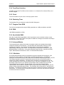
3.15 Drop and Insert (D&I)
The Radyne DMD15/DMD15L Drop and Insert (D&I) Function provides an interface between a full
T1 or E1 Trunk whose framing is specified in CCITT G.704 and a fractional Nx64 Kbps Satellite
Channel that conforms to the IBS and small IDR Framing Structures. The Drop function allows
the user to select the terrestrial T1 or E1 timeslots that are to be dropped off for transmission over
the link in the specified satellite channels.
The Insert function allows the user to select the T1 or E1 timeslots into which the received satellite
channels are to be inserted. The two functions are completely independent allowing maximum
flexibility in choosing configurations. The four-port G.703 Interface allows one or more modems to
be looped together using the same T1 or E1 trunk.
The Transmit Data Trunk is brought into the modem via the Send Data In (SDI) Port. From there,
the TX Baseband Processor extracts the selected timeslots from the G.704 Frame and prepares
them for transmission. The original trunk data is sent out of the modem unaltered via the Send
Data Out (SDO) Port. The Receive Data Trunk is brought into the modem via the Insert Data In
(IDI) Port. The data is buffered inside the modem and the RX Baseband Processor inserts
satellite data into the selected timeslots in the G.704 Frame. The modified terrestrial trunk is then
output via the Receive Data Out (RDO) Port.
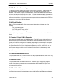
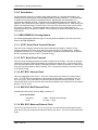
Figure 3-8 shows two modems looped together. This configuration could be simplified to just use
one modem, or extended to use more than two modems. Figure 3-9 shows an alternative method
of looping where all of the drop (transmit) data is processed prior to performing any insert
(receive) processing. In both configurations, the terrestrial trunk is providing the timing for the
satellite transmission and for the terrestrial receive.
TM051 - Rev. 5.8
3-13
Operation
DMD15/DMD15L IBS/IDR Satellite Modem
Figure 3-8. Looped Modems
Figure 3-9. Looped Modems with Separate D&I Trunks
3-14
TM051 – Rev. 5.8
DMD15/DMD15L IBS/IDR Satellite Modem
Operation
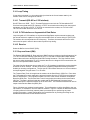
3.15.1 Drop Only
When Drop is enabled and Insert is disabled, the DMD15/DMD15L performs a drop-only function.
Framed E1 or T1 Data is input via the Send Data In Port, the selected timeslots are dropped into
the IBS frame structure, and the unaltered terrestrial data is output via the Send Data Out Port
(refer to Figure 3-10).
Figure 3-10. Drop Only
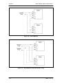
3.15.2 Insert Only
When Insert is enabled and Drop is disabled, the DMD15/DMD15L performs an insert-only
function. If framed terrestrial E1 or T1 Data is available, it should be input via the Insert Data In
Port. The Terrestrial Data is buffered inside the Modem. The RX Baseband Processor inserts
satellite data into the selected timeslots in the G.704 Frame and the modified terrestrial data is
then output via the Receive Data Out Port (refer to Figure 3-11).
If framed terrestrial data is not available, selection of the Internal T1/E1 frame source will cause
the modem to generate the required G.704 Frame. The Satellite Data will be inserted into the
selected timeslots, and the resulting terrestrial data will be output via the Receive Data Out Port.
Any non-inserted timeslots in the G.704 Frame will be filled with the appropriate Idle Code (refer to
Figure 3-12).
Figure 3-11. Insert Only with Eternal Frame Source
TM051 - Rev. 5.8
3-15
Operation
DMD15/DMD15L IBS/IDR Satellite Modem
Figure 3-12. Insert Only with Internal Frame Source
3.16 Mode Selection
The DMD15/DMD15L D&I can be easily configured to support several commonly used terrestrial
data formats. For E1 Data, the user can choose between PCM-30, PCM-30C, PCM-31 and PCM31C. For T1 Data, the user can choose between T1-D4, T1-ESF, and SLC-96. The following
paragraphs provide more information on the various mode selection capabilities of the
DMD15/DMD15L.
3.16.1 PCM-30
The PCM-30 Mode of Operation supports an E1 Interface with Multiframe Alignment (MFAS) and
Channel Associated Signaling (CAS). The user may independently program n timeslots to drop
and n timeslots to insert where n = 1, 2, 3, 4, 5, 6, 8, 10, 12, 15, 16, 20, 24, or 30. In addition to
the selected drop timeslots, the Transmit Function also extracts the appropriate ABCD signaling
bits from terrestrial timeslot 16 for transmission in IBS Frame as required. Conversely, the
Receive Function extracts received ABCD signaling bits from the IBS Frame and inserts them in
timeslot 16 of the appropriate terrestrial frame. This transmission and reception of ABCD
signaling based upon the drop and insert timeslots is performed automatically and is transparent
to the user. In PCM-30 mode, the user may not select timeslot 16 as a Drop or Insert Timeslot.
3.16.2 PCM-30C
The PCM-30C Mode of Operation supports an E1 Interface with Multiframe Alignment (MFAS)
and Channel Associated Signaling (CAS). In addition, the Drop function verifies the received
terrestrial CRC checksum and the Insert function calculates the required CRC checksum. The
user may independently program n timeslots to drop and n timeslots to insert where n = 1, 2, 3, 4,
5, 6, 8, 10, 12, 15, 16, 20, 24, or 30. In addition to the selected Drop timeslots, the Transmit
Function also extracts the appropriate ABCD signaling bits from terrestrial timeslot 16 for
transmission in IBS Frame as required. Conversely, the Receive Function extracts received
ABCD signaling bits from the IBS frame and inserts them in timeslot 16 of the appropriate
terrestrial frame. This transmission and reception of ABCD signaling based upon the Drop and
Insert timeslots is performed automatically and is transparent to the user. In PCM-30C Mode, the
user may not select timeslot 16 as a Drop or Insert Timeslot.
3.16.3 PCM-31
The PCM-31 Mode of Operation supports an E1 Interface with no Multiframe Alignment (MFAS)
or Channel Associated Signaling (CAS). The user may independently program n timeslots to drop
and n timeslots to insert where n = 1, 2, 3, 4, 5, 6, 8, 10, 12, 15, 16, 20, 24, or 30. Because there
is no implied ABCD signaling, the user is free to select timeslot 16 as a Drop or Insert Timeslot.
3-16
TM051 – Rev. 5.8
DMD15/DMD15L IBS/IDR Satellite Modem
Operation
3.16.4 PCM-31C
The PCM-31C Mode of Operation supports an E1 Interface with no Multiframe Alignment (MFAS)
or Channel Associated Signaling (CAS). In addition, the Drop Function verifies the received
terrestrial CRC checksum and the Insert Function calculates the required CRC checksum. The
user may independently program ‘n’ timeslots to drop and ‘n’ timeslots to insert where ‘n’ = 1, 2, 3,
4, 5, 6, 8, 10, 12, 15, 16, 20, 24, or 30. Because there is no implied ABCD signaling, the user is
free to select timeslot 16 as a Drop or Insert Timeslot.
3.16.5 T1-D4/T1-D4-S
The T1-D4 Mode of Operation supports a T1 Interface with 12 frames per multiframe. The user
may independently program n timeslots to drop and n timeslots to insert where n = 1, 2, 3, 4, 5, 6,
8, 10, 12, 15, 16, 20, 24, or 30. In the DMD15/DMD15L, Robbed Bit Signaling (RBS) is handled
without any need for operator intervention and is transparent to the user.
3.16.6 T1-ESF/ T1-ESF-S
The T1-ESF Mode of Operation supports a T1 Interface with 24 frames per multiframe. The
CRC-6 checksum is automatically checked by the Drop Function and generated by the Insert
Function and placed in the appropriate F-bit positions in the terrestrial multiframe. The user may
independently program n timeslots to drop, and n timeslots to insert, where n = 1, 2, 3, 4, 5, 6, 8,
10, 12, 15, 16, 20, 24, or 30. In the DMD15/DMD15L, Robbed Bit Signaling (RBS) is handled
without any need for operator intervention and is transparent to the user.
3.16.7 SLC-96
The T1 SLC-96 Mode supports a T1 Interface with 12 Frames per Multiframe (as per T1-D4) with
the following exceptions:
The signaling frames (Fs bits) are sent twice in succession.
During the subsequent four signaling frames, the Fs bits are replaced with data link
information bits.
The data frame is composed of six signaling frames with a length of 9 msec. The user may
independently program n timeslots to drop, and n timeslots to insert, where n = 1, 2, 3, 4, 5, 6, 8,
10, 12, 15, 16, 20, 24, or 30. In the DMD15/DMD15L, Robbed Bit Signaling (RBS) is handled
without any need for operator intervention and is transparent to the user.
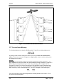
3.17 Multidestinational Systems
Because the Drop and Insert Functions are completely independent, the DMD15/DMD15L easily
supports multidestinational communications. Figure 3-13 illustrates a Multidestinational System
with one Hub site and three remote sites. At the Hub site, thirty channels are being transmitted to
all three remote sites and a fractional set of channels is being received from each remote site. At
the other end of the link, each remote site is transmitting a fractional E1 to the Hub site as well as
receiving all thirty (30) channels from the Hub site. It also identifies those channels intended for it,
and inserts them into the terrestrial data stream.
TM051 - Rev. 5.8
3-17
Operation
DMD15/DMD15L IBS/IDR Satellite Modem
Figure 3-13. Multidestinational Communications
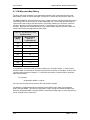
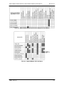
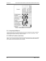
3.17 Drop and Insert Mapping
The following displays under Interface D&I Setup (both Tx and Rx), are editing displays only:
SATCh TS
Enter to Edit
Any changes made in these displays are made on the screen, but are not entered into the
modem. Once these menus are configured, the Mapping Menu must be used to actually enter
the settings into the modem.
Example :
For a modem w/ Drop & Insert enabled at a data rate of 256 (with timeslots assigned 1-1, 2-2,
etc.). At a data rate of 256, the modem will allow 4 channels to assign timeslots to. Under the Tx
Menu, assign the timeslots that are to be used to the 4 channels. CH1 is assigned to TS1
(Timeslot #1), CH2 to TS 2, CH3 to TS3 and CH4 to TS4, <ENTER> must be depressed after
assigning each individual TS. Once the timeslots are assigned to the channels, use the Left or
Right Arrow Key to scroll to the Mapping Menu. This menu will appear in the following way:
Map
*******
Copy
*******
This is the menu where the channel assignments are actually entered into the modem. To do
this, perform the following steps:
3-18
TM051 – Rev. 5.8
DMD15/DMD15L IBS/IDR Satellite Modem
Operation
For the Transmit Side:
1.
Push <ENTER> to get the flashing cursor.
2.
Use the Up Arrow Key to make the left portion of the display read “TX EDIT”.
3.
Use the Right or Left Arrow Keys to switch the flashing cursor to the right portion
of the display.
4.
Use the Up or Down Arrow Key to make the right hand portion read “TX ACTIVE”.
5.
The mapping display should now look like this:
Map
Copy
TX EDIT > TX ACTIVE
6.
Push <ENTER> to enter this command. This tells the modem to configure to the
settings that were assigned in the Channel/Timeslot display.
For the Receive Side:
1.
With Rx Side Channels configured as follows: CH1 to TS1, CH2 to TS2, CH3 to
TS3 and CH4 to TS4.
2.
After the timeslots are assigned properly, scroll to the Mapping Menu and use the
above procedure to enter the settings into the modem.
3.
Set the display to read:
Map
Copy
RX EDIT > RX ACTIVE
4.
Press <ENTER> to enter the settings into the modem.
To View the current Timeslot Assignment:
1.
If there is a question of the channels not being entered properly, the Mapping
Menu may be used to see how the channels/timeslots are configured in the
modem.
2.
Use <ENTER> and the Arrow Keys to make the mapping menu read (for the Tx
Side):
Map
Copy
TX ACTIVE > TX EDIT
3.
Press <ENTER>. The modem has now copied the current Tx Settings to the Tx
Channel/Timeslot Display.
4.
For the Rx Side:
Map
Copy
RX ACTIVE > RX EDIT
TM051 - Rev. 5.8
3-19
Operation
5.
DMD15/DMD15L IBS/IDR Satellite Modem
Press <ENTER>. The modem has now copied the current Rx Settings to the Rx
Channel/Timeslot display ).
Note: It is not mandatory to assign timeslots in sequential order, although the
lowest timeslot must be entered in the lowest channel. For example: timeslots may
be assigned 1-2, 2-5, etc. but not 1-5, 2-2.
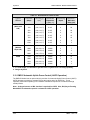
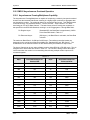
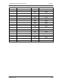
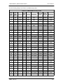
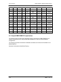
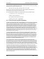
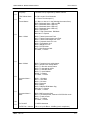
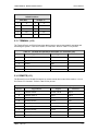
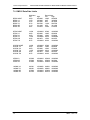
3.18 Reed-Solomon Codec (Refer to Figures 3-14, 3-15, and Table 3-1)
Utilizing a Reed-Solomon (RS) Outer Codec concatenated with a Convolutional Inner Codec is an
effective way to produce very low error rates even for poor signal-to-noise ratios while requiring
only a small increase in transmission bandwidth. Typically, concatenating an RS Codec requires
an increase in transmission bandwidth of only 9 – 12% while producing a greater than 2 dB
improvement in Eb/No. RS is a block Codec where K data bytes are fed into the encoder which
adds 2t = (N – K) check bytes to produce an N byte RS block. The RS decoder can then correct
up to “t” erred bytes in the block.
3.18.1 Operation in the DMD15/DMD15L
When the Reed-Solomon Codec is enabled, data is fed to the RS Encoding Section of the
DMD15/DMD15L where it is scrambled, formed into blocks, RS encoded, and interleaved.
Unique words are added so that the blocks can be reformed in the Receiving Modem (Refer to
Figure 3-13). Data is then sent to the modulator where it is convolutionally encoded, modulated
and transmitted to the satellite.
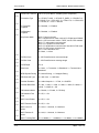
When the signal is received and demodulated by the Receiving Modem, it is fed to a Viterbi
Decoder for the first layer of error correction. After error correction is performed by the Viterbi
Decoder, the unique words are located and the data is deinterleaved and reformed into blocks.
The RS Decoder then corrects the leftover errors in each block. The data is then descrambled
and output from the RS Section.
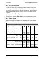
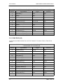
3.18.2 Reed-Solomon Code Rate
The RS Code Rate is defined by (N, K) where N is the total RS block size in bytes - data + check
bytes - and K is the number of data bytes input into the RS Encoder. The transmission rate
expansion required by the RS Codec is then defined by N/K. The DMD15/DMD15L automatically
sets the correct RS code rate for IDR/IBS open network operation in accordance with the data
shown in Table 3-1. In Closed Net Mode, the DMD15/DMD15L allows any N or K setting up to N
= 255, and K = 235 to allow tailoring of the code rate to meet system requirements.
3.18.3 Interleaving
The DMD15/DMD15L allows for interleaving depths of 4 or 8 RS Blocks. This allows burst errors
to be spread over 4 or 8 RS blocks in order to enhance the error correcting performance of the
RS Codec. For Open Network Modes, the DMD15/DMD15L automatically sets the interleaving
depth to 4 for QPSK or BPSK or 8 for 8PSK. In Closed Network Mode, the interleaver depth can
be manually set to 4 or 8.
Figure 3-14. Reed-Solomon Encoder Functional Block Diagram
3-20
TM051 – Rev. 5.8
DMD15/DMD15L IBS/IDR Satellite Modem
Operation
Figure 3-15. Reed-Solomon Decoder Functional Block Diagram
TM051 - Rev. 5.8
3-21
Operation
DMD15/DMD15L IBS/IDR Satellite Modem
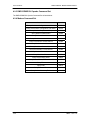
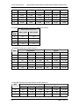
Table 3-1. Reed-Solomon Codes for IDR
2
Type of
Service
Data Rate
(Kbps)
RS Code (n,
1
k, t)
Bandwidth
Expansion
[ (n/k) -1 ]
Interleaving
Depth
Maximum
RS Codec
Delay (ms)
Small IDR
(With 16/15
O/H)
64
(126, 112, 7)
0.125
4
115
128
(126, 112, 7)
0.125
4
58
256
(126, 112, 7)
0.125
4
29
384
(126, 112, 7)
0.125
4
19
512
(126, 112, 7)
0.125
4
15
768
(126, 112, 7)
0.125
4
10
1024
(126, 112, 7)
0.125
4
8
1536
(126, 112, 7)
0.125
4
5
1544
(225, 205,10)
0.0976
4
9
2048
(219, 201, 9)
0.0896
4
7
6312
(194, 178, 8)
0.0899
4
2
8448
(194, 178, 8)
0.0899
4
<2
1544
(219, 201, 9)
0.0896
8
18
2048
(219, 201, 9)
0.0896
8
13
6312
(219, 201, 9)
0.0896
8
4
8448
(219, 201, 9)
0.0896
8
3
IDR
(With 96
Kbps O/H)
8PSK
NOTES:
1. n = code length, k = information symbols and t = symbol error correcting capability.
2. Design objective.
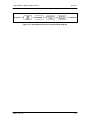
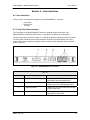
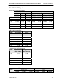
3.19 DMD15 Automatic Uplink Power Control (AUPC Operation)
The DMD15 Modem has an optional built-in provision for Automatic Uplink Power Control (AUPC).
AUPC attempts to maintain a constant Eb/No at the receive end of an SCPC link. This is
especially useful when operating over a satellite at Ku-Band Frequencies in locations with high
rainfall periods.
Note: An Asynchronous or IBS Interface is required for AUPC. Also, IBS (Async Framing
Mode MUST be selected to provide a channel for AUPC operation.
3-22
TM051 – Rev. 5.8
DMD15/DMD15L IBS/IDR Satellite Modem
Operation
The IBS Async Framer Data Mode provides a service channel between the two sites of a link
permitting the modem processors to send messages and get responses over this channel. AUPC
can be set to operate on either or both directions of a link but always requires a bi-directional
channel. Therefore, both the Modulator and Demodulator interface mode must be set to IBS
Async for the AUPC menus to be visible and for the AUPC function to operate properly. The
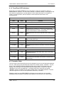
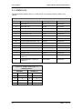
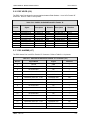
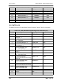
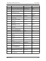
AUPC Functions and their descriptions are shown on Table 3-2.
Table 3-2. AUPC Functions
Function
Description
AUPC ENABLE/DISABLE
Enables/Disables the AUPC to function locally
AUPC Eb/No
Desired Eb/N0 of remote modem
AUPC MIN LVL
Sets minimum output power to be used
AUPC MAX LVL
Sets maximum output power to be used
AUPC DEF LVL
Sets default output power to be used
Note: The AUPC menus are located under the Modulator Menu as shown in Section 4.
The basic AUPC Operation is described as follows:
Assume that the two modems, one at each end of the link, are set to AUPC operation. Only one
direction is discussed, but the same functions could be occurring in both directions
simultaneously. Modem “A” is transmitting to modem “B” under normal conditions and modem “B”
has a receive Eb/No of 7.5 dB. Modem “A” has been set to an AUPC Eb/No on the Front Panel of
7.5 dB, and is currently outputting –15 dBm. Next, it begins raining at location “B”, and the Eb/No
drops to –7.0 then –6.8 dB. Modem “B” is constantly sending update messages to “A” and reports
the current Eb/No. When “A” sees the drop in Eb/No, it slowly begins to raise the output power, and
raises it again when it sees further drops. As the rain increases in intensity, and the Eb/No
decreases again, “A” continues to increase its power level to compensate, and when the rain
diminishes and quits, it lowers its power level to compensate. The operation is therefore a
feedback control loop with the added complication of a significant time delay.
There are safeguards built into the AUPC System. First, the Modulator has two additional
parameters, which allow control of the Maximum and Minimum Power Output Levels. Second, a
default power level is specified which takes precedence over the output power level during signal
loss or loss of AUPC Channel Communication. The default power level should normally be set to
a high enough level to reestablish communication regardless of rain fade. The other controls are
built into the operating control software to limit response times and detect adverse operating
conditions.
TM051 - Rev. 5.8
3-23
Operation
DMD15/DMD15L IBS/IDR Satellite Modem
3.20 DMD15 Asynchronous Overhead Operation
3.20.1 Asynchronous Framing/Multiplexer Capability
The Asynchronous Framing/Multiplexer is capable of multiplexing a relatively low-speed overhead
channel onto the terrestrial data stream resulting in a slightly higher combined or aggregate data
rate through the modem. The overhead channel is recovered at the far end. This added channel
is termed variously “An Overhead Channel”, ”Service Channel”, “Async Channel” or in IESS
terminology an “ES to ES Data Channel.” The basic frame structure used by the multiplexer is
that specified in the IESS-309 Standard, resulting in a 16/15 Aggregate to Through-Data Ratio.
For Regular Async:
(Standard IBS), the Baud Rate is approximately 1/2000
of the Data Rate listed in Table 3-3.
For Enhanced Async:
(IBS Async.), the Baud Rate is selectable, but Data Rate
is limited.
The maximum Baud Rate is 19,200 bps for IBS Async. Two software-controlled modes are
designed into the card to best utilize the available bits; “Standard IBS” and “IBS (Async)”. The
characteristics of the Channel Interface is also determined by the standard or Async mode.
The Async Channel can be set under software-control to either RS-232 or RS-485 mode. The pin
assignments for both modes are shown in Table 3-3. The “RS-485” Setting controls the output
into tri-state when the modem is not transmitting data, allowing multiple modem outputs to be
connected together.
Table 3-3
3-24
Kbps
Baud Rate Example for
Standard IBS
Kbps
Baud Rate Example for
Enhanced Mode
128
64
9.6
300
256
128
19.2
600
384
192
32
600
512
256
64
1200
640
320
128
2400
768
384
192
4800
896
448
256
4800
1024
512
320
9600
1152
576
384
9600
1280
640
448
9600
1408
704
512
9600
1536
768
576
9600
1664
832
640
19200
1792
896
704
19200
1920
960
768
19200
1920
960
768
19200
2048
1024
832
19200
TM051 – Rev. 5.8
DMD15/DMD15L IBS/IDR Satellite Modem
TM051 - Rev. 5.8
Operation
896
19200
960
19200
1024
19200
1088
19200
1152
19200
1216
19200
1280
19200
1344
19200
1408
19200
1472
19200
1536
19200
1600
19200
1664
19200
1728
19200
1792
19200
1856
19200
1920
19200
1984
19200
2048
19200
3-25
Operation
DMD15/DMD15L IBS/IDR Satellite Modem
3.21 Standard IBS Mode
In the first or “Normal” mode, all bit assignments are per the IBS standard. The bits of Overhead
Housekeeping byte 32 are implemented as shown in Table 3-4 below:
Table 3-4.
Bit 1
ES to ES Data
Channel
This bit is routed directly to the ES to ES Data Channel.
th
th
Its data rate is 1/512 of the aggregate rate (or 1/480 of
the through terrestrial data rate), and is normally used to
super-sample an asynchronous data channel.
Bit 2
Frame Alignment
Part of the Frame Alignment word.
Bit 3
Backward Alarm
Transmit and Receive with main processor to activate
Main Alarm/LED.
Bit 4
Multiframe Message
As per IBS.
Bits 5 and 6
Spare
Not currently utilized.
Bits 7 and 8
Encryption Utilization
Not currently utilized.
The ratio of the Through Terrestrial Data Channel Rate to the aggregate rate is 15/16. The
standard transmit and receive channels of the ES to ES Data Channel in Standard IBS Mode are
raw channels operating at the specific bit rate as controlled by the data channel rate, without
buffering. In addition, no clocks are provided with this channel. Since it would be rare that the
data rate provided was exactly that required for a standard rate device, the only method of
communicating using this channel is to allow it to super-sample the user data.
3.22 Asynchronous Multiplexer Mode
Since many of the frame bits in the standard IBS mode are not used, an “Enhanced” Multiplexer
Mode has been implemented that can be engaged under software control. Since this mode
changes the use of many of the framed non-data bits, this mode is only usable when the DMD15
is at both ends of a link. In this mode, the overhead signaling bytes 16 and 48 can be used to
implement a significantly higher speed ES to ES Data Channel under software control. When
th
implemented, this rate is 16 times that of the normal IBS standard, or 1/30 of the terrestrial data
nd
rate (1/32 of the aggregate rate).
Note: The IBS Async mode MUST be selected for true Asynchronous channel operation to
be available.
3.23 ESC Backward Alarms
When running in IDR Mode and if the modem has the ESC Option, there will be four Backward
Alarms available for use by the earth stations at each end of the link (both ends must have the
ESC option). These alarms are accessed via the ESC ALARMS Port. The four alarms are
controlled by four relays, each having a normally open, normally closed, and a common
connection. The common connections of these relays (referred to as Backward Alarm Inputs) can
be connected to whichever system on the earth station that the user wishes to trigger the
backward alarm. When ground is applied to the Common (Input) Connection of one of these
relays, that relay and associated backward alarm will then be in a “no fault” state. When the
ground is removed, the relay and the associated Tx Backward Alarm will toggle to the faulted
state. When in the faulted state, the receive end of the link will receive that backward alarm that
is initiated at the transmit end of the link.
3-26
TM051 – Rev. 5.8
DMD15/DMD15L IBS/IDR Satellite Modem
Operation
The user can connect whichever systems on the earth stations that they desire to these Backward
Alarms Relays as long as they will supply ground to the Backward Alarm Relay Input in the “no
fault” condition and the ground will be removed in the “faulted” condition.
For example: the user could connect the Demod Summary Fault of the modem to the Backward
Alarm 1 Input, so that if the demod went into Major Alarm (such as a Carrier Loss), Backward
Alarm 1 would be transmitted to the receive end of the link. At the receive end, it would show up
as Rx Backward 1 (Receive Backward Alarm 1).
3.23.1 To Disable the ESC Backward Alarms
If the ESC ALARMS Port will not be used and the Backward Alarm Indications are to be disabled,
connect the following pins of the ESC ALARMS Port:
Connect Pins 1, 10, 11, 22 and 23 (connect all together). Pin 1 is ground and Pins 10, 11, 22, and
23 are the inputs of Backward Alarms 1 through 4. By connecting these four pins to ground (Pin
1) the Backward Alarms will be disabled and indicate “PASS” for BK1 through BK4.
3.24 Reacquisition
Reacquisition on the DMD15/DMD15L is the ability to reacquire a lost signal from a far end
modulator that returns at some point. The DMD15/DMD15L allows the user to program the
amount of time (0.0 – 900.0 seconds) that the demodulator will wait for the signal to reappear
before searching the entire programmed sweep range for the signal. Additionally, the
DMD15/DMD15L allows the user to specify the range (± 0 – 32000 Hz) in which the demodulator
will perform the narrow signal search (see Figure 3-16). Configuration can be accomplished via
the standard user interfaces (front panel, dumb terminal, remote).
TM051 - Rev. 5.8
3-27
Operation
DMD15/DMD15L IBS/IDR Satellite Modem
Acquire Signal
Sweep Delay
OPCode
0x2A05
0.0 - 900.0 sec
No
No
Locked
Yes
Sweep
Delay != 0
Yes
Track current
frequency
No
Yes
Normal
operation
No
Timer
Expired
Locked
Use
reacquisition
sweep limits to
acquire signal
Reacquisition
limits
OPCode
0x2A2F
0 - 32000 Hz
Start Delay
Timer
Yes
Go back to
normal sweep
limits to
acquire signal
Figure 3-16. Reacquisition flow in the DMD15/DMD15L
3-28
TM051 – Rev. 5.8
DMD15/DMD15L IBS/IDR Satellite Modem
TM051 - Rev. 5.8
Operation
3-29
DMD15/DMD15L IBS/IDR Satellite Modem
User Interfaces
Section 4 – User Interfaces
4.0 User Interfaces
There are three user interfaces available for the DMD15/DMD15L. These are:
•
•
•
Front Panel
Remote Port
Terminal
4.1 Front Panel User Interface
The Front Panel of the DMD15/DMD15L allows for complete control and monitor of all
DMD15/DMD15L parameters and functions via a keypad, LCD display and status LEDs.
The front panel layout is shown in Figure 4-1, showing the location and labeling of the front panel.
The front panel is divided into four functional areas: the LCD Front Panel Display, the Cursor
Control Arrow Keys, the Numeric Keypad, and the Front Panel LED Indicators, each described
below in Table 4-1.
Figure 4-1. DMD15/DMD15L Front Panel
Table 4-1.
Item Number
Description
Function
1
LCD Front Panel Display
Displays DMD15/DMD15L Operating
parameters and Configuration data
2
Cursor Control Arrow Keys
Controls the up, down, right and left motion
of the cursor in the LCD Display window
3
Numeric Keypad
Allows entry of numeric data and Clear and
Enter function keys
4
Front Panel LED Indicators
See Paragraph 4.1.2 below for an itemized
description of these LEDs
TM051 - Rev. 5.8
4-1
User Interfaces
DMD15/DMD15L IBS/IDR Satellite Modem
4.1.1 LCD Front Panel Display
The front panel display is a 2 line by 16-character LCD display. The display is lighted and the
brightness can be set to increase when the front panel is currently in use. The LCD display
automatically dims after a period of inactivity. The display has two distinct areas showing current
information. The upper area shows the current parameter being monitored, such as ‘Frequency’
or ‘Data Rate’. The lower line shows the current value of that parameter. The LCD display is a
single entry window into the large matrix of parameters that can be monitored and set from the
Front Panel.
4.1.2 Cursor Control Arrow Keys
A set of ‘Arrow’ or ‘Cursor’ keys (↑), (↓), (→), (←), is used to navigate the parameter currently
being monitored or controlled. Table 4-2 describes the functions available at the Front Panel.
4.1.3 Numeric Keypad
A 10 Key Numeric Keypad with 2 additional keys for the ‘Enter’ and ‘Clear’ function allows the
entry of data into the system. Table 4-2 describes the functions available at the Front Panel.
Table 4-2.
Edit Mode Key Functions (Front Panel Only)
Parameter
Type
0–9
↑
Fixed Point Changes Digit Toggles ±
Decimal
(If Signed)
↓
←
→
‘Clear’ &
←
‘Clear’ &
→
Toggles ±
(If Signed)
Moves
Cursor 1
Position
Left
Moves
Cursor 1
Position
Right
N/A
N/A
Moves
Cursor 1
Position
Left
Moves
Cursor 1
Position
Right
N/A
N/A
Unsigned Changes Digit Increments Decrements
Hexadecimal
Digit Value Digit Value
Enumerated
N/A
Previous
Value in
List
Next
Value in
List
N/A
N/A
N/A
N/A
N/A
N/A
Moves
Cursor 1
Position
Left
Moves
Cursor 1
Position
Right
N/A
N/A
IP Address Changes Digit Increments Decrements
Digit Value Digit Value
Moves
Cursor 1
Position
Left
Moves
Cursor 1
Position
Right
N/A
N/A
Text Strings
Moves
Cursor 1
Position
Left
Moves
Cursor 1
Position
Right
Clears to
Left of
Cursor
Inclusive
Clears to
Right of
Cursor
Inclusive
Date/ Time Changes Digit
4-2
Changes
Character
Increments Decrements
Character
Character
Value
Value
TM051 – Rev. 5.8
DMD15/DMD15L IBS/IDR Satellite Modem
User Interfaces
4.1.4 Front Panel LED Indicators
Eight LEDs on the DMD15/DMD15L Front Panel (Refer to Table 4-3) indicate the status of
DMD15/DMD15L operation. The LED colors maintain a consistent meaning. Green signifies that
the indication is appropriate for normal operation, Yellow means that there is a condition not
proper for normal operation, and Red indicates a fault condition that will result in lost
communications.
Table 4-3.
LED
Color
Function
Modem LED Indicators
Power
Green
Indicates that the unit is turned on.
Fault
Red
Event
Yellow
Indicates that a condition or event has occurred that the
modem has stored in memory. The events may be viewed
from the Front Panel or in the Terminal Mode.
Remote
Green
Indicates that the unit is set to respond to the remote control
input.
Indicates a hardware fault for the unit.
Demodulator LED Indicators
Signal Lock
Green
Indicates that the receiver locked to an incoming carrier and
data, including FEC Sync.
Major Alarm
Red
Indicates that the Receive Direction has failed, losing traffic.
Minor Alarm
Yellow
Indicates that a Receive Warning Condition exists.
Test Mode
Yellow
Indicates that the receiver is involved in a current Test Mode
activity.
Modulator LED Indicators
Transmit ON
Green
Indicates that the transmitter is on.
Major Alarm
Red
Minor Alarm
Yellow
Indicates that a Transmit Warning Condition exists.
Test Mode
Yellow
Indicates that the transmitter is involved in a current Test
Mode activity.
Indicates that the terrestrial data and/or clock is not being
supplied to the unit.
4.2 Parameter Setup
The four Cursor Control Arrow Keys are used to navigate the menu tree and select the parameter
to be set. After arriving at a parameter that needs to be modified, depress <ENTER>. The first
space of the modifiable parameter highlights (blinks) and is ready for a new parameter to be
entered. After entering the new parameter using the keypad (Refer to Figure 4-2), depress
<ENTER> to lock in the new parameter. If a change needs to be made prior to pressing
<ENTER>, depress <CLEAR> and the display defaults back to the original parameter. Depress
<ENTER> again and re-enter the new parameters followed by <ENTER>.
Following a valid input, the DMD15/DMD15L will place the new setting into the nonvolatile
EEPROM making it available immediately and available the next time the unit is powered-up.’
TM051 - Rev. 5.8
4-3
User Interfaces
DMD15/DMD15L IBS/IDR Satellite Modem
Figure 4-2. Entering New Parameters
4.3 Front Panel Control Screen Menus
The DMD15/DMD15L Front Panel Control Screens are broken down into sections under several
Main Menus.
4.3.1 Main Menus
Modulator
Demodulator
Interface
Monitor
Alarms
System
Test
4.3.2 Modulator Menu Options and Parameters
Mode:
{IDR, IBS, Closed Net, Drop & Insert}
Used with IDR, or IBS Interface Only.
The Mode Command sets a number of parameters
within the modem to meet a set specification. The
purpose is to eliminate keystrokes and potential
compatibility problems.
Additionally, data rates not covered by the given mode of
operation will not be allowed. If the mode of operation is
selected after the data rate has been entered, then the
data rate must be compatible with the desired mode of
operation or the mode will not be allowed. The following
parameters are set for the given mode of operation and
4-4
TM051 – Rev. 5.8
DMD15/DMD15L IBS/IDR Satellite Modem
User Interfaces
cannot be changed while the unit is in the given mode of
operation:
IDR Mode:
(IESS-308)
For Data rates 1.544, 2.048, 6.312, 8.448 Mbps
Framing Type:
96 Kbps (IDR)
Scrambler Type:
V.35
Spectrum Mask:
Intelsat
For Data Rates < 1.544
Framing Type:
1/15 (IBS)
Scrambler Type:
IESS-309
Spectrum Mask:
Intelsat
IBS Mode:
(IESS-309)
For Data Rates < 2048
Framing Type:
1/15 (IBS)
Scrambler Type:
IESS-309
Spectrum Mask:
Intelsat
Closed Net:
All possible combinations allowed. Activates the
AUPC Menu.
Drop & Insert:
Data Rates:
Framing Type:
Scrambler Type:
Spectrum Mask:
TM051 - Rev. 5.8
n x 64 n = 1, 2, 3, 4, 5, 6, 8,
10,12, 15, 16, 20, 24, 30
1/15 (IBS)
IESS-309
Intelsat
4-5
User Interfaces
Strap Code:
DMD15/DMD15L IBS/IDR Satellite Modem
{Refer to Strap Code Guide, Table 4-4}
The Strap Code is a quick set key that sets many
modem parameters. Consult the strap code guide for
available strap codes. Parameters set by strap code:
Data Rate
Code Rate
Mode
Frame Type
Scrambler Type
Spectrum Mask
Mod IF (menu):
4-6
Frequency:
{50 – 90 MHz, 100 – 180 MHz, or 950 – 1750 MHz (LBand)}
Allows the user to enter the Modulator IF Frequency in 1
Hz increments.
Power:
{+5 to –20 dBm} {-5 to –30 L-Band}
Allows the user to enter the Transmitter Power Level.
The DMD15 has a digital/analog crossover point at -7.4
to -7.5 dBm (-17.4 to -17.5 dBm L-Band) when the output
power level setting crosses this threshold, the modulator
may glitch and undershoot the output momentarily.
Carrier Ctrl:
{On, Off}
The DMD15 transmitter will turn off the carrier output
automatically when the modem determines there is a
major alarm. This is done to prevent the carrier from
outputting an unknown spectrum and possibly disturbing
adjacent carriers. This automatic drop of the carrier can
be overridden by masking the alarm that is causing the
fault. This will keep the modulator output spectrum
transmitting, even when the fault occurs.
Spectrum Inv:
{Normal, Inverted}
Allows the user to invert the direction of rotation for PSK
Modulation. Normal meets the IESS Specification.
Modulation:
{QPSK, BPSK, OQPSK, 8PSK, 16QAM}
Allows the user to select the modulation type.
Spectrl Msk:
{Intelsat}
Allows the user to set the spectral shape of Tx Data
Filter.
TM051 – Rev. 5.8
DMD15/DMD15L IBS/IDR Satellite Modem
User Interfaces
Mod Data (menu):
Data Rate:
{Refer to Technical Specs for Data Rates}
Allows the user to set the Data Rate in bps steps via the
Front Panel Arrows or Keypad.
Symbol Rate:
Allows the user to view the Symbol Rate.
Conv Enc:
{1/2 Rate VIT, 3/4 Rate VIT, 7/8 Rate VIT,
Optional encoders: 1/2 Rate SEQ, 3/4 Rate SEQ , 7/8
Rate SEQ , 2/3 Rate TRE (8PSK), Turbo (.793), Turbo
(.495), 3/4 Rate CSC}
Allows the user to select the Tx Code Rate and Type.
Diff Encode:
{On, Off, EF Mode*}
Allows the user to enable or disable the Differential
Encoder. Having the encoder enabled ensures proper
phase lock.
*EF Mode is a special differential encoder mode that
allows compatibility with certain modems when
configured in QPSK modulation, and uncoded FEC.
Scrmbl Sel:
{None, V.35-IESS, V.35 CITT, V.35 EF, IBS, CCITT,
V.35FC, OM73, V.35EF_RS, TPC SCRAMBLER(Turbo
Codec)}
Allows the user to select the scrambler type.
Scrmbl Ctrl:
Allows the user to enable or disable scrambler operation.
Mod Framing:
{1/15 (IBS), 1/15 (Async), 96 Kbps (IDR), None}
Used with IDR, IBS, or Asynchronous Interface Only.
Allows the user to select the framing type.
Data Invert:
{Terr, Base, Terr & Base}
Allows the user to invert the Tx Data polarity.
Symbol Pair:
{None, Swapped}
Allows the user to swap the I&Q Channels.
(BPSK Mode Only)
Reed-Solomon (menu):
These selections are visible only when the ReedSolomon Option is installed.
Enable/Disable
{Enable, Disable}
Allows the user to Enable/Disable the Reed-Solomon
Encoder.
RS Codes
{Refer to Appendix A for valid n/k values}
Displays the currently used n, k Reed-Solomon Codes.
In Closed Net Mode, the user may select custom RS
Codes.
RS Depth
{4, 8}
Allows the user to select the Reed-Solomon interleaver
depth. In Closed Net Mode, a depth of 4 or 8 may be
selected.
TM051 - Rev. 5.8
4-7
User Interfaces
DMD15/DMD15L IBS/IDR Satellite Modem
4.3.3 Demodulator Menu Options and Parameters
Mode:
{IDR, IBS, Closed Net, Drop & Insert}
Used with IDR, or IBS Interface Only.
The Mode Command sets a number of parameters
within the modem to meet a set specification. The
purpose is to eliminate keystrokes and potential
compatibility problems. Additionally, data rates not
covered by the given mode of operation will not be
allowed. If the mode of operation is selected after the
data rate has been entered, then the data rate must be
compatible with the desired mode of operation or the
mode will not be allowed. The following parameters are
set for the given mode of operation and cannot be
changed while the unit is in the given mode of operation:
IDR Mode:
(IESS-308)
For Data rates 1.544, 2.048, 6.312, 8.448 Mbps
Framing Type:
96 Kbps (IDR)
Descrambler type:
V.35
Spectrum Mask:
Intelsat
For Data Rates < 1.544 Mbps
Framing Type:
1/15 (IBS)
Descrambler Type:
IESS-309
Spectrum Mask:
Intelsat
IBS Mode:
(IESS-309)
For Data Rates < 2.048 Mbps
Framing Type:
1/15 (IBS)
Descrambler Type:
IESS-309
Spectrum Mask:
Intelsat
Closed Net:
All possible combinations allowed
Drop & Insert:
Data Rates:
Framing Type:
Descrambler Type:
Spectrum Mask:
Strap Code:
n x 64, n = 1, 2, 3, 4, 5, 6, 8, 10,
12, 15, 16, 20, 24, 30
1/15 (IBS)
IESS-309
Intelsat
{Refer to Strap Code Guide, Section 4.3, Table 4-4}
The Strap Code is a quick set key that sets many
modem parameters. Consult the strap code guide for
available strap codes. Parameters set by strap code:
Data Rate
Code Rate
Mode
Frame Type
Scrambler Type
Spectrum Mask
4-8
TM051 – Rev. 5.8
DMD15/DMD15L IBS/IDR Satellite Modem
User Interfaces
Demod IF (menu):
Frequency:
{50 – 90 MHz, 100 – 180 MHz, or 950 – 1750 MHz (LBand)}
Allows the user to enter the Modulator IF Frequency in 1
Hz increments.
Spectrum Inv:
{Normal, Inverted}
Allows the user to invert the direction of rotation for PSK
Modulation. Normal meets the IESS Specification.
Demodulation:
{QPSK, BPSK, OQPSK, 8PSK, 16QAM}
Allows the user to select the demodulation type.
Spectrl Msk:
{Intelsat}
Allows the user to set the spectral shape of Tx Data
Filter.
Swp Bound:
{±0 – 32 kHz}
Allows the user to set the acquisition range for the
demodulator
Swp Delay:
{0.0 – 900.0 sec}
Allows the user to set the reacquisition delay time in
th
1/10 second increments. (See section 3.24 for a
complete description of the DMD15/DMD15L
reacquisition.
ReAcq Sweep:
{0 – 32000 Hz}
Allows the user to set the reacquisition sweep in 1 Hertz
increments. (See section 3.24 for a complete description
of the DMD15/DMD15L reacquisition.
TM051 - Rev. 5.8
4-9
User Interfaces
DMD15/DMD15L IBS/IDR Satellite Modem
Demod Data (menu):
4-10
Data Rate:
{Refer to Technical Specs for Data Rates}
Allows the user to set the Data Rate in bps steps via the
Front Panel Arrows or Keypad.
Symbol Rate:
Allows the user to view the Symbol Rate.
Conv Dec:
{1/2 Rate VIT, 3/4 Rate VIT, 7/8 Rate VIT,
Optional encoders
1/2 Rate SEQ, 3/4 Rate SEQ , 7/8 Rate SEQ , 2/3 Rate
TRE (8PSK), Turbo (.793), Turbo (.495), 3/4 Rate
CSC}
Allows the user to select the Tx Code Rate and Type.
Diff Decode:
{On, Off, EF Mode*}
Allows the user to enable or disable the Differential
Decoder. Having the decoder enabled ensures proper
phase lock.
*EF Mode is a special differential decoder mode that
allows compatibility with certain modems when
configured in QPSK modulation, and uncoded FEC.
Dscrmbl Sel:
{None, V.35-IESS, V.35 CITT, V.35 EF, IBS, CCITT,
V.35FC, OM73, V.35EF_RS, TPC SCRAMBLER (Turbo
Codec)}
Allows the user to select the descrambler type.
Dscrmbl Ctrl
{On, Off}
Allows the user to enable or disable the descrambler
operation.
Dmd Framing:
{1/15 (IBS), 1/15 (Async), 96 Kbps (IDR), None}
Used with IDR, IBS, or Asynchronous Interface Only.
Allows the user to select the Framing Type.
Data Invert:
{Terr, Base, Terr & Base}
Allows the user to invert the Rx Data polarity.
Symbol Pair:
{None, Swapped}
Allows the user to swap the I&Q Channels.
(BPSK Mode Only)
TM051 – Rev. 5.8
DMD15/DMD15L IBS/IDR Satellite Modem
Reed-Solomon (menu):
User Interfaces
These selections are visible only when the ReedSolomon Option is installed.
Enable/Disable
{Enable, Disable}
Allows the user to Enable/Disable the Reed-Solomon
Encoder.
RS Codes
{Refer to Appendix A for valid n/k values}
Displays the currently used n, k Reed-Solomon Codes.
In Closed Net Mode, the user may select custom RS
Codes.
RS Depth
{4, 8}
Allows the user to select the Reed-Solomon interleaver
depth. In Closed Net Mode, a depth of 4 or 8 may be
selected.
4.3.4 Interface Menu Options and Parameters
Tx Setup (menu):
Tx Ckt ID:
Allows the user entry of a Tx Circuit Identifier. Circuits
can be given up to an 11 Character alphanumeric identity
such as LINK1.
Tx Type:
{G.703, V.35, RS-232, RS-422}
Allows the user to select the Transmit Type.
Tx Clock:
{SCTE (External), SCT (Internal), SCR, EXT CLK}
Allows the user to select the Transmit Clock Source.
Clk Polarity:
{Auto, Normal, Inverted}
Allows the user to select the Clock Polarity for the Tx
Terrestrial Clock relative to the Tx Data. “Auto” detects
wrong polarity and automatically corrects. If G.703
Interface is selected, this selection cannot be changed.
SCT Source:
{INTERNAL (SCT), SCR (Rx SAT CLK)}
Allows the user to select SCT Source to be either the
SCT Oscillator or RX Satellite Clock. Rx SAT CLK is
used for loop timing.
ESC CH#1
{+10 to -20}
Available only in IDR Mode at a valid IDR Rate. Controls
the volume of the ESC Channels.
ESC CH#2
See above.
TM051 - Rev. 5.8
4-11
User Interfaces
DMD15/DMD15L IBS/IDR Satellite Modem
Tx D&I (menu):
Drop Mode:
{Enable, Disable}
Allows the user to enable or disable the following:
T1-D4, T1-ESF, PCM-30, PCM-30C, PCM-31,
PCM-31C, SLC-96, T1-D4-S, T1-ESF-S.
Map Copy:
{Rx Edit, Tx Edit, Rx Acti, Tx Acti, ROM 1…ROM 8,
User 1…User 8}
Allows user to copy Drop and Insert maps. If the user
attempts an invalid copy, the error prompt “BAD
DESTINATION” will be displayed and the copy will not be
allowed. The Tx Active map is the drop map currently
being used by the modem. For a more detailed
description of this function, see Section 4.6.4.
SATCh TS:
Allows the user to edit the Tx Edit Map to specify the
terrestrial slots that will be dropped into which satellite
channels. The Satellite Channels are fixed and the
number of channels are determined by the data rate.
The Terrestrial Timeslots available are determined by the
Drop Mode. When the user has finished editing the Tx
Edit map, it must be copied to the Tx Active map before
it can be used by the modem.
Time Mark:
{Enable, Disable}
Allows the user to enable or disable the “Time Mark
Transfer” (TMT) Transmit Request External Input to
initialize the state machine that detects the proper states
of I and Q and inserts the TMT Pattern into the transmit
symbol stream. This feature is only available in BPSK,
QPSK, and OQPSK Modulations and requires specific
hardware and configuration at the factory.
TMT Length:
{4, 5, 6, 7, 8, 9, 10, 11, 12, 13, 14, 15, 16}
Allows the user to set the length of the pattern marker.
This feature is only available in BPSK, QPSK, and
OQPSK Modulations and requires specific hardware and
configuration at the factory.
Rx Setup (menu):
4-12
Rx Ckt ID:
Provides entry of Rx Circuit Identifier. Circuits can be
given up to an 11 Character alphanumeric Identity such
as DLINK1
Rx Type:
{G.703 (Balanced/Unbalanced), V.35, RS-232, RS422}
Allows the user to select the Receive Type.
Buff Size:
{0-32 msecs}
Allows the user to set the Doppler Buffer Size in msec.
Buff Clk:
{SCTE (External), SCT (Internal), Rx Sat, EXTCLK}
TM051 – Rev. 5.8
DMD15/DMD15L IBS/IDR Satellite Modem
User Interfaces
Allows the user to select the buffer clock source. Must
set Buff size to zero to bypass.
Clk Polarity:
{Normal, Inverted}
Allows the user to select the Buffer Clock Polarity for the
Tx Terrestrial Clock relative to the Tx Data. If G.703
Interface is selected, this selection cannot be changed.
Rx D&I (menu):
Insert Mode:
{Enable, Disable}
Allows the user to enable or disable the following:
T1-D4, T1-ESF, PCM-30, PCM-30C, PCM-31, PCM31C, SLC-96, T1-D4-S, T1-ESF-S.
T1E1 Frm Src
{Internal, External}
Selects frame source for T1 or E1 framing.
Map Copy:
{Rx Edit, Tx Edit, Rx Acti, Tx Acti, ROM 1…ROM 8,
User 1…User 8}
Allows user to copy Drop and Insert maps. If the user
attempts an invalid copy, the error prompt “BAD
DESTINATION” will be displayed and the copy will not be
allowed. The Rx Active map is the drop map currently
being used by the modem. For a more detailed
description of this function, see Section 4.6.4.
SATCh TS:
Allows the user to edit the Tx Edit Map to specify the
terrestrial slots that will be dropped into which satellite
channels. The Satellite Channels are fixed and the
number of channels is determined by the data rate. The
Terrestrial Timeslots available are determined by the
Drop Mode. When the user has finished editing the Tx
Edit map, it must be copied to the Tx Active map before
it can be used by the modem.
TMT Length:
{4, 5, 6, 7, 8, 9, 10, 11, 12, 13, 14, 15, 16}
Allows the user to set the length of the pattern marker.
This feature is only available in BPSK, QPSK, and
OQPSK Modulations and requires specific hardware and
configuration at the factory.
General:
Freq Ref Src:
{Internal, External, High Stability}
Allows the user to select the Frequency Reference
Source.
Async (menu):
TM051 - Rev. 5.8
ES Mode:
{Normal, Enhanced (option)}
Allows user to choose between Normal and Enhanced
Async Mode if the enhanced option is available.
ES Interface:
{RS-232, RS-485}
Allows user to select between RS-232 or -485
4-13
User Interfaces
DMD15/DMD15L IBS/IDR Satellite Modem
ES Baud:
{150-19200}
Allows the user to select the baud rate in Enhanced
Async mode. Available rates are listed in Sect 3.20.1
ES Data Bits:
{7,8}
Allows the user to choose between 7 or 8 bit data.
4.3.5 AUPC Menu Options and Parameters
Note: AUPC Menus are only available when the Modulator is in ‘Closed Net’ Mode and
Framing is ‘EFAUPC 1/15’.
Local AUPC (menu):
4-14
The 'LOCAL AUPC CONFIGURATION' Menu contains
the local configuration parameters for the AUPC
Function.
AUPC Enable:
{Off, On}
Allows the user to enable or disable the Local AUPC
Function of the local modem. The Local AUPC Function
is the response to the commands for an increase or
decrease of the Transmit Power in 0.5 dB steps. The
command to change to the setting is indicated in the
'REMOTE CL ACTION' Menu upon receiver loss of lock
of the remote modem.
Nominal TX Power:
{variable through power range}
Allows the user to set the nominal Transmit Power. The
nominal Transmit Power is the setting that will be used
when the remote modem indicates that its receiver has
lost lock and commands a change to the setting
indicated in the 'REMOTE CL ACTION' Menu. That
change will only be implemented if the 'REMOTE CL
ACTION' Menu is set to “NOMINAL”.
Minimum TX Power:
{variable through power range}
Allows the user to set the minimum Transmit Power.
The minimum Transmit Power is the lowest power
setting that will be used when the remote modem
commands a decrease of the Transmit Power.
Maximum TX Power:
{variable through power range}
Allows the user to set the maximum Transmit Power.
The maximum Transmit Power is the highest power
setting that will be used when the remote modem
commands an increase of the Transmit Power. It is the
setting that will be used when the remote modem
indicates that its receiver has lost lock and commands a
change to the setting indicated in the 'REMOTE CL
ACTION’, Menu. That change will only be implemented
if the 'REMOTE CL ACTION' Menu is set to “MAXIMUM”.
Target Eb/No:
{variable}
Allows the user to set the desired Eb/No for the local
receiver. This setting is compared against the receive
TM051 – Rev. 5.8
DMD15/DMD15L IBS/IDR Satellite Modem
User Interfaces
Eb/No and commands to the remote modem to increase
or decrease Transmit Power accordingly are sent.
Tracking Rate:
{0.5 to 6.0}
Allows the user to set the rate at which the commands to
increase or decrease Transmit Power are sent. Each
command will result in a 0.5-dB increase or decrease in
Transmit Power from the remote transmitter. The
tracking rate is adjustable from 0.5 dB per minute to 6.0
dB per minute in 0.5 dB steps. The resulting 'command
rate' is 1 command every minute to 1 command every
five seconds.
Local CL Action:
{HOLD, NOMINAL, MAXIMUM}
Allows the user to set the Transmit Power Setting to be
used when the local modem receiver loses lock. The
setting can be 'HOLD' (no action taken), 'NOMINAL' (the
nominal Transmit Power Setting is used), and
'MAXIMUM' (the maximum Transmit Power Setting is
used).
Remote CL Action:
{HOLD, NOMINAL, MAXIMUM}
Allows the user to set the Transmit Power Setting to be
used when the remote modem receiver loses lock. The
setting can be 'HOLD' (no action taken), 'NOMINAL' (the
nominal Transmit Power Setting is used), and
'MAXIMUM' (the maximum Transmit Power Setting is
used).
TM051 - Rev. 5.8
4-15
User Interfaces
Remote AUPC (menu):
AUPC Enable:
DMD15/DMD15L IBS/IDR Satellite Modem
The 'REMOTE AUPC CONFIGURATION' menu contains
the remote configuration parameters for the AUPC
Function.
{OFF, ON}
Allows the user to enable or disable the AUPC Function
of the remote modem. The remote AUPC Function is
the response of the local modem to commands for an
increase or decrease of the Transmit Power in 0.5 dB
steps and the command to change to the setting
indicated in the 'REMOTE CL ACTION' menu of the
remote modem upon receiver loss of lock.
Loopback:
Allows the user to enable or disable the Baseband
Loopback Test Mode of the remote modem.
TX 2047 Pattern:
Allows the user to enable or disable the Transmit 2047
Pattern Test Mode of the remote modem.
Remote AUPC Monitor:
Remote 2047 BER:
The ‘REMOTE AUPC MONITOR’ Menu contains the
remote monitor status for the AUPC Function.
Reports the BER measurement of the receiver 2047
Pattern Test Mode of the remote modem. BER is
-5
-7
reported from the 1x10 to 1x10 in tenth decade steps.
If the pattern does not synchronize or is out of range,
‘NO DATA’ will be displayed.
4.3.6 Monitor Menu Options and Parameters
Level:
Displays the estimated receive signal level as seen by
the Demodulator.
Eb/No:
Displays the estimated Eb/No as seen by the
demodulator.
SER:
Displays the estimated channel error rate (before
decoding) measured by the modem.
CBER:
Displays the estimated corrected bit error rate (after
decoding).
Error Count:
Displays the current error count from the Viterbi
Decoder.
Offset Freq:
Displays the received carrier frequency offset as
measured by the modem.
4-16
TM051 – Rev. 5.8
DMD15/DMD15L IBS/IDR Satellite Modem
User Interfaces
Event Buff:
Displays a history of events recorded in the event buffer.
A maximum of 40 events may be stored in the buffer.
st
Upon receipt of the 41 event, the first received event is
automatically deleted, and so on, maintaining the
maximum 40 events.
Press Clr to Erase Events:
Clears the contents of the Event Buffer.
Voltages (menu):
+5 Volt:
Displays the measured voltage of the +5 Volt power bus
located inside the modem.
+12 Volt:
Displays the measured voltage of the +12 Volt power bus
located inside the modem.
-12 Volt:
Displays the measured voltage of the -12 Volt power bus
located inside the modem.
Buffer:
Displays the status of the Doppler Buffer from 0 to 100%.
Press Clr to Center Buffer:
Causes Doppler Buffer to re-center.
BER Exponent:
{6 - 9}
Allows the user to set the time base for the Channel
Error Rate Measurement, used to estimate Eb/No.
4.3.7 Alarms Menu Options and Parameters
Active Alrms (menu):
Masking alarms may cause undesirable modem performance.
Major Tx (menu):
TxuProc Mask:
Status
Edit Table
{Pass/Fail, No/Yes}
Indicates a Hardware Transmit or DSP Failure within the
modem.
(Yes = Masked, No = Unmasked)
TM051 - Rev. 5.8
TxPower Mask:
{Pass/Fail, No/Yes}
Indicates that the Modem Tx Output Power is within
allowed tolerance. A solid indication indicates a
hardware or programming failure within the modem.
TxOSClk Mask:
{Pass/Fail, No/Yes}
Indicates that the TX Oversample Clock PLL is not
locked. This alarm will flash on during certain modem
4-17
User Interfaces
DMD15/DMD15L IBS/IDR Satellite Modem
parameter changes. A solid indication indicates a
hardware or programming failure within the modem.
CompClk Mask:
{Pass/Fail, No/Yes}
Indicates that Tx Composite Clock PLL is not locked.
This alarm will flash on during certain modem parameter
changes. A solid indication indicates a problem with the
incoming clock to the modem (SCTE).
TxSynth Mask:
{Pass/Fail, No/Yes}
Indicates that the Tx IF Synthesizer is not locked. This
alarm will flash on during certain modem parameter
changes. A solid indication indicates a hardware or
programming failure within the modem.
Major Rx (menu):
RxuProc Mask:
{Pass/Fail, No/Yes}
Indicates a hardware failure within the modem.
SigLoss Mask:
{Pass/Fail, No/Yes}
Indicates that the demod is unable to lock to a signal.
MfrSync Mask:
{Pass/Fail, No/Yes}
Indicates that the Framing Unit is unable to find the
expected framing pattern.
FrmSync Mask:
{Pass/Fail, No/Yes}
Indicates that the Framing Unit is unable to find the
expected framing pattern.
IF Syn Lock:
{Pass/Fail, No/Yes}
Indicates the Rx IF Synthesizer is not locked. This alarm
will flash ON during certain modem parameter changes.
A solid indication indicates a hardware or programming
failure within the modem.
Rx Ovrsmp Lk:
{Pass/Fail, No/Yes}
Indicates that the RX Oversample Clock PLL is not
locked. This alarm will flash on during certain modem
parameter changes. A solid indication indicates a
hardware or programming failure within the modem.
Buf Clk Lock:
{Pass/Fail, No/Yes}
Indicates that the Buffer Clock PLL is not locked. This
alarm will flash ON during certain modem parameter
changes. A solid indication indicates a problem with the
Receive Buffer Clock.
Minor Tx (menu):
Tx Activity (menu):
4-18
TM051 – Rev. 5.8
DMD15/DMD15L IBS/IDR Satellite Modem
User Interfaces
TerrClk Mask:
{Pass/Fail, No/Yes}
Indicates no Terrestrial Clock activity.
IntClk Mask:
{Pass/Fail, No/Yes}
Indicates no SCT Clock activity.
TxSatCk Mask:
{Pass/Fail, No/Yes}
Indicates no Tx Sat Clock activity.
Tx Data Mask:
{Pass/Fail, No/Yes}
Indicates no Tx Data activity.
TerrAIS Mask:
{Pass/Fail, No/Yes}
Indicates that AIS has been detected in the Tx Data
Stream.
Drop Alarms (menu):
Frm Lock:
{Pass/Fail, No/Yes}
Indicates if drop/insert data is frame locked.
Multiframe Lock:
{Pass/Fail, No/Yes}
Indicates if drop/insert data has multiframe lock.
CRC Lock:
{Pass/Fail, No/Yes}
Indicates if the Circular Redundancy Check is passing in
PCM30C and PCM31C Mode.
RS FIFO:
{Pass/Fail, No/Yes}
Indicates status of the Tx Reed-Solomon FIFO.
FllBack:
{Pass/Fail, No/Yes}
Indicates Tx clock fallback.
Minor Rx (menu):
BufUFLw Mask:
{Pass/Fail, No/Yes}
Indicates that a Doppler Buffer underflow has occurred.
BufOFLw Mask:
{Pass/Fail, No/Yes}
Indicates that a Doppler Buffer overflow has occurred.
Buf <10% Mask:
{Pass/Fail, No/Yes}
Indicates that the Doppler Buffer is about to underflow.
Buf >90% Mask:
{Pass/Fail, No/Yes}
Indicates that the Doppler Buffer is about to overflow.
Viterbi Lock:
{Pass/Fail, No/Yes}
Indicates that the Viterbi Decoder is not locked.
Eb/No Mask:
{Pass/Fail, No, Yes}
Indicates that the calculated Eb/No of the incoming
signal has fallen below the programmed threshold value.
Rx Activity (menu):
TM051 - Rev. 5.8
4-19
User Interfaces
DMD15/DMD15L IBS/IDR Satellite Modem
Buf Clk Mask:
{Pass/Fail, No/Yes}
Indicates that the selected buffer clock source is not
active.
Rx Sat Mask:
{Pass/Fail, No/Yes}
Indicates that the Rx Sat buffer clock source is not
active.
Insert Mask:
{Pass/Fail, No/Yes}
Indicates that the Insert buffer clock source is not active.
RX Data Mask:
{Pass/Fail, No/Yes}
SatAIS Mask:
{Pass/Fail, No/Yes}
Insert Alarms (menu):
Frm Lock Mask:
{Pass/Fail, No/Yes}
Multiframe Lock:
{Pass/Fail, No/Yes}
CRC Lock Mask:
{Pass/Fail, No/Yes}
T1 Signaling:
{Pass/Fail, No/Yes}
Rx RS Faults (menu):
Dec Lock Mask:
{Pass/Fail, No/Yes}
Indicates status of the Reed-Solomon Decoder Lock
Dintlvr Mask:
{Pass/Fail, No/Yes}
Indicates status of the Reed-Solomon de-interleaver
word fault
UnCWord Mask:
{Pass/Fail, No/Yes}
Indicates status of the Reed-Solomon uncoded word
fault.
IBS BER Mask:
{Pass/Fail, No/Yes}
Indicates that more than 1 bit in 1000 is in error in IBS
Mode.
RxLvl Mask:
{Pass/Fail, No/Yes}
Indicates if Rx level is below allowable limits.
Fllback Mask:
{Pass/Fail, No/Yes}
Indicates Rx Clock fallback.
Common (menu):
-12 Power:
4-20
{Pass/Fail, No/Yes}
Indicates power supply voltage out of range.
TM051 – Rev. 5.8
DMD15/DMD15L IBS/IDR Satellite Modem
TM051 - Rev. 5.8
User Interfaces
+12 Power:
{Pass/Fail, No/Yes}
Indicates power supply voltage out of range.
+5 Power:
{Pass/Fail, No/Yes}
Indicates power supply voltage out of range.
Battery:
{Pass/Fail, No/Yes}
Indicates that internal clock battery is low.
RAM/ROM:
{Pass/Fail, No/Yes}
Indicates M&C memory fault.
M&C uProc:
{Pass/Fail, No/Yes}
Indicates M&C Microprocessor hardware failure.
UIO Present:
{Pass/Fail, No/Yes}
Indicates absence of Universal Input/Output Module
(UIM) Hardware
IF Present:
{Pass/Fail, No/Yes}
Indicates absence of IF hardware detect.
Ext Ref Lock:
{Pass/Fail, No/Yes}
Indicates that the External Reference PLL is not locked.
Ext EXC Act:
{Pass/Fail, No/Yes}
Indicates that the External Clock is not active.
4-21
User Interfaces
DMD15/DMD15L IBS/IDR Satellite Modem
Ext Ref Mask:
{Pass/Fail, No/Yes}
Indicates no activity on the External Reference.
HiStab Mask:
{Pass/Fail, No/Yes}
Indicates if High Stability Oscillator is active.
Latched Alrm (menu):
The following alarms are latched in order to catch
intermittent failures:
Note: Refer to Section 4.2.7, “Active Alrms (menu)” for an explanation of these Menu
Options and Parameters.
Major Tx (menu):
TxuProc:
TxPower:
TxOSClk:
CompClk:
TxSynth:
Major Rx (menu):
RxuProc:
SigLoss:
MfrSync:
FrmSync:
IBS BER:
RxIFSynLock:
RxOSPLLLock:
Buf Clk Lock:
Minor Tx (menu):
4-22
There are currently no Latched Minor Tx alarms.
TM051 – Rev. 5.8
DMD15/DMD15L IBS/IDR Satellite Modem
User Interfaces
Minor Rx (menu):
RxBuf Alarms (menu):
BufUFlw:
BufOFLw:
Buf<10%:
Buf>90%:
Rx Activity (menu):
RxSat:
RxData:
SatAIS:
InsClk:
Common (menu):
-12 Power:
+12 Power:
+5 Power:
Battery:
RAM/ROM:
M&C uProc:
Ext Ref Lock:
Backward Alr (menu):
Backward alarms are alarms that are fed back to or
received from the other end of the satellite link. In IBS
Mode (including Drop & Insert), Backward Alarm 1 is the
only one used. It would be received if the distant end
demod drops lock.
Backward 1:
{Rcv = yes/no, Force = yes/no}
Backward 2:
{Rcv = yes/no, Force = yes/no}
Backward 3:
{Rcv = yes/no, Force = yes/no}
Backward 4:
{Rcv = yes/no, Force = yes/no}
DIYellow:
{Force = yes/no}
MapSummaryTo (menu):
Backward 1:
TM051 - Rev. 5.8
{Xmt = no/yes}
4-23
User Interfaces
DMD15/DMD15L IBS/IDR Satellite Modem
Backward 2:
{Xmt = no/yes}
Backward 3:
{Xmt = no/yes}
Backward 4:
{Xmt = no/yes}
Clear Alarms:
Allows the user to reset the latched alarms.
4.3.8 System Menu Options and Parameters
Control Mode:
{Front Panel, Terminal, Computer}
Allows the user to select the active control source.
Config Copy
Allows settings in Config 1-5 or current settings to be
copied into another config slot.
General (menu):
Date:
{YY MM DD}
Allows the user to enter the current date.
Time:
{HH:MM:SS}
Allows the user to enter the current time.
Backlight (menu):
4-24
Level:
{High, Low}
Allows the user to enter the backlight intensity level.
Timeout:
{00 - 99}
Allows the user to enter the length of time (in seconds) of
keyboard inactivity before the backlight shuts off. 00 =
no timeout.
Key Click:
{On, Off}
Allows the user to enable or disable the audible click
heard each time a key is pressed.
Eb/No Alarm Thrsh
{0.0 – 9.9 dB}
The EB/No Threshold is a value set by the user to allow
the modem to alert thr user, via a demodulator minor
alarm, that the Eb/No calculated by the demodulator has
reached or exceeded the programmed limit. The modem
default value is 0.0 dB.
Radyne DMD15 Version X.X:
Modem Version
TM051 – Rev. 5.8
DMD15/DMD15L IBS/IDR Satellite Modem
User Interfaces
Firmware Rev (menu):
Interface (menu):
UIO Code:
UIO Xilinx:
M&C:
Term Baud:
{Same as remote baud listed below}
Displays the Terminal Port Baud Rate.
Emulation:
{VT100, ADDS-VP, WYSE 50}
Allows the user to select the Terminal Emulation Mode
for the Terminal Port.
Remote Addr:
{32 - 255}
Allows the user to enter the Remote Port Multidrop
Address.
Remote Baud:
{150, 300, 600, 1200, 2400, 4800, 9600, 19200, 38,400}
Allows the user to enter the Remote Port Baud Rate.
4.3.9 Test Menu Options and Parameters
2047 Test:
{None, Tx, Rx, Tx/Rx}
Allows the user to enable or disable the 2047 Pattern
Test. “Tx” enables the transmit pattern generator. “Rx”
enables the receive pattern checker. “Tx/Rx” enables
both.
Insert Errors:
{0000 - 9999}
Allows the user to select the number of errors to insert.
Once the number of errors to insert has been selected,
pressing ‘Enter’ twice causes the number of errors
shown to be inserted in the data stream.
2047 Errors:
{No Sync, nnnn}
Displays the number of errors detected by the 2047
Pattern checker.
2047 BER:
{No Sync, nnnn x 10 }
Displays the measured BER for the 2047 Pattern.
Clear 2047:
{Ent = Y, Clr = N}
Restarts 2047 BER Test.
TM051 - Rev. 5.8
-9
4-25
User Interfaces
Loopbacks:
DMD15/DMD15L IBS/IDR Satellite Modem
Terrestrial Loopback is performed at the Terrestrial
Interface
IF:
IF loopback loops the IF output of the Modulator to the IF
input of the Demodulator. If using 8PSK or 16QAM
modulation the output power must be above –15 dB.
Tx Terr:
Sends Tx Terrestrial Data to Rx data out.
Rx Terr:
(Distant Loop) Sends received satellite data to the
Modulator for transmission to the distant end.
Tx/Rx Terr:
Enables both. Baseband loopback is performed at
interface between the Baseband Processor Card and the
Modem Card. This ensures Framer/Deframer integrity.
Tx BB:
Sends Tx data to the receive input to the BB Card.
Rx BB:
Sends Rx data from the Modem Card to the Tx data
input to the Modem Card.
Tx/RX BB:
Enables both.
CW:
Causes the Modulator to output a pure carrier.
Dual:
Causes a double sideband output.
Offset:
Causes a single sideband output.
Normal:
Causes the Modulator to output normal modulation.
Pos Fir:
For manufacturer’s use only.
Neg Fir:
For manufacturer’s use only.
Carrier:
4.4 DMD15/DMD15L Strap Codes
The Strap Code is a quick set key that sets many of the modem parameters. For quick setup of
the DMD15/DMD15L, Strap Codes are very helpful. When a Strap Code is entered, the modem is
automatically configured for the code’s corresponding data rate, overhead, code rate, framing,
scrambler type and modulation. An example of how to set a strap code follows:
Example: At the Front Panel <Modulator> Menu, depress ‘↓’, then move ‘→’ to the ‘Strap Code’
Submenu and enter #16. The DMD15/DMD15L will be automatically configured to the parameters
shown below in the highlighted row ‘Strap Code 16’.
4-26
TM051 – Rev. 5.8
DMD15/DMD15L IBS/IDR Satellite Modem
User Interfaces
Use the following Strap Code Guide for available strap codes.
Table 4-4. DMD15/DMD15L Strap Codes
Strap
Code
(DEC)
Data
Code
Rate Overhead
Rate Framing
(Kbps)
Scrambler
Drop and
Insert
ReedSolomo
n
Modulation
1
64
16/15
1/2
IBS
IBS
DISABLE DISABLE
QPSK
2
128
16/15
1/2
IBS
IBS
DISABLE DISABLE
QPSK
3
256
16/15
1/2
IBS
IBS
DISABLE DISABLE
QPSK
5
384
16/15
1/2
IBS
IBS
DISABLE DISABLE
QPSK
6
512
16/15
1/2
IBS
IBS
DISABLE DISABLE
QPSK
9
768
16/15
1/2
IBS
IBS
DISABLE DISABLE
QPSK
4
1536
16/15
1/2
IBS
IBS
DISABLE DISABLE
QPSK
10
1920
16/15
1/2
IBS
IBS
DISABLE DISABLE
QPSK
8
2048
16/15
1/2
IBS
IBS
DISABLE DISABLE
QPSK
12
2048
1*
1/2
IBS
IBS
DISABLE DISABLE
QPSK
16
1544
96K
3/4
IDR
V.35 (IESS)
DISABLE DISABLE
QPSK
32
2048
96K
3/4
IDR
V.35 (IESS)
DISABLE DISABLE
QPSK
64
6312
96K
3/4
IDR
V.35 (IESS)
DISABLE DISABLE
QPSK
128
8448
96K
3/4
IDR
V.35 (IESS)
DISABLE DISABLE
QPSK
24
56
1
1/2
CNT
V.35 (IESS)
DISABLE DISABLE
QPSK
33
56
1
3/4
CNT
V.35 (IESS)
DISABLE DISABLE
QPSK
34
64
1
1/2
CNT
V.35 (IESS)
DISABLE DISABLE
QPSK
36
64
1
3/4
CNT
V.35 (IESS)
DISABLE DISABLE
QPSK
40
128
1
1/2
CNT
V.35 (IESS)
DISABLE DISABLE
QPSK
48
128
1
3/4
CNT
V.35 (IESS)
DISABLE DISABLE
QPSK
65
256
1
1/2
CNT
V.35 (IESS)
DISABLE DISABLE
QPSK
66
256
1
3/4
CNT
V.35 (IESS)
DISABLE DISABLE
QPSK
68
320
1
1/2
CNT
V.35 (IESS)
DISABLE DISABLE
QPSK
72
320
1
3/4
CNT
V.35 (IESS)
DISABLE DISABLE
QPSK
80
384
1
1/2
CNT
V.35 (IESS)
DISABLE DISABLE
QPSK
96
384
1
3/4
CNT
V.35 (IESS)
DISABLE DISABLE
QPSK
129
512
1
1/2
CNT
V.35 (IESS)
DISABLE DISABLE
QPSK
130
512
1
3/4
CNT
V.35 (IESS)
DISABLE DISABLE
QPSK
132
768
1
1/2
CNT
V.35 (IESS)
DISABLE DISABLE
QPSK
136
768
1
3/4
CNT
V.35 (IESS)
DISABLE DISABLE
QPSK
144
896
1
1/2
CNT
V.35 (IESS)
DISABLE DISABLE
QPSK
TM051 - Rev. 5.8
4-27
User Interfaces
DMD15/DMD15L IBS/IDR Satellite Modem
44
896
1
3/4
CNT
V.35 (IESS)
DISABLE DISABLE
QPSK
7
1344
1
1/2
CNT
V.35 (IESS)
DISABLE DISABLE
QPSK
11
1344
1
3/4
CNT
V.35 (IESS)
DISABLE DISABLE
QPSK
13
1536
1
1/2
CNT
V.35 (IESS)
DISABLE DISABLE
QPSK
14
1536
1
3/4
CNT
V.35 (IESS)
DISABLE DISABLE
QPSK
19
1544
1
1/2
CNT
V.35 (IESS)
DISABLE DISABLE
QPSK
21
1544
1
3/4
CNT
V.35 (IESS)
DISABLE DISABLE
QPSK
22
1920
1
1/2
CNT
V.35 (IESS)
DISABLE DISABLE
QPSK
25
1920
1
3/4
CNT
V.35 (IESS)
DISABLE DISABLE
QPSK
26
2048
1
1/2
CNT
V.35 (IESS)
DISABLE DISABLE
QPSK
28
2048
1
3/4
CNT
V.35 (IESS)
DISABLE DISABLE
QPSK
37
2368
1
1/2
CNT
V.35 (IESS)
DISABLE DISABLE
QPSK
38
2368
1
3/4
CNT
V.35 (IESS)
DISABLE DISABLE
QPSK
41
48
1
1/2
CNT
V.35 (IESS)
DISABLE DISABLE
QPSK
160
1544
3072/
2895
1/2
IBS
IBS
DISABLE DISABLE
QPSK
52
1920
16/15
3/4
IBS
IBS
DISABLE DISABLE
QPSK
69
6312
1
3/4
CNT
V.35 (IESS)
DISABLE DISABLE
QPSK
70
8448
1
3/4
CNT
V.35 (IESS)
DISABLE DISABLE
QPSK
73
3152
1
1/2
CNT
V.35 (IESS)
DISABLE DISABLE
QPSK
74
3152
1
3/4
CNT
V.35 (IESS)
DISABLE DISABLE
QPSK
76
3264
1
1/2
CNT
V.35 (IESS)
DISABLE DISABLE
QPSK
81
3264
1
3/4
CNT
V.35 (IESS)
DISABLE DISABLE
QPSK
88
512
16/15
3/4
IBS
IBS
DISABLE DISABLE
QPSK
97
1024
1
1/2
CNT
V.35 (IESS)
DISABLE DISABLE
QPSK
98
1024
1
3/4
CNT
V.35 (IESS)
DISABLE DISABLE
QPSK
112
64
16/15
3/4
IBS
IBS
DISABLE DISABLE
QPSK
131
128
16/15
3/4
IBS
IBS
DISABLE DISABLE
QPSK
133
256
16/15
3/4
IBS
IBS
DISABLE DISABLE
QPSK
134
192
16/15
1/2
IBS
IBS
DISABLE DISABLE
QPSK
137
192
16/15
3/4
IBS
IBS
DISABLE DISABLE
QPSK
138
320
16/15
1/2
IBS
IBS
DISABLE DISABLE
QPSK
140
320
16/15
3/4
IBS
IBS
DISABLE DISABLE
QPSK
145
384
16/15
3/4
IBS
IBS
DISABLE DISABLE
QPSK
100
448
16/15
1/2
IBS
IBS
DISABLE DISABLE
QPSK
146
448
16/15
3/4
IBS
IBS
DISABLE DISABLE
QPSK
4-28
TM051 – Rev. 5.8
DMD15/DMD15L IBS/IDR Satellite Modem
User Interfaces
104
576
16/15
1/2
IBS
IBS
DISABLE DISABLE
QPSK
148
576
16/15
3/4
IBS
IBS
DISABLE DISABLE
QPSK
152
640
16/15
1/2
IBS
IBS
DISABLE DISABLE
QPSK
161
640
16/15
3/4
IBS
IBS
DISABLE DISABLE
QPSK
162
704
16/15
1/2
IBS
IBS
DISABLE DISABLE
QPSK
164
704
16/15
3/4
IBS
IBS
DISABLE DISABLE
QPSK
168
768
16/15
3/4
IBS
IBS
DISABLE DISABLE
QPSK
193
832
16/15
1/2
IBS
IBS
DISABLE DISABLE
QPSK
194
832
16/15
3/4
IBS
IBS
DISABLE DISABLE
QPSK
196
896
16/15
1/2
IBS
IBS
DISABLE DISABLE
QPSK
208
896
16/15
3/4
IBS
IBS
DISABLE DISABLE
QPSK
224
960
16/15
1/2
IBS
IBS
DISABLE DISABLE
QPSK
15
960
16/15
3/4
IBS
IBS
DISABLE DISABLE
QPSK
23
1024
16/15
1/2
IBS
IBS
DISABLE DISABLE
QPSK
27
1024
16/15
3/4
IBS
IBS
DISABLE DISABLE
QPSK
29
1536
16/15
3/4
IBS
IBS
DISABLE DISABLE
QPSK
30
1088
16/15
1/2
IBS
IBS
DISABLE DISABLE
QPSK
39
1088
16/15
3/4
IBS
IBS
DISABLE DISABLE
QPSK
43
1152
16/15
1/2
IBS
IBS
DISABLE DISABLE
QPSK
46
1152
16/15
3/4
IBS
IBS
DISABLE DISABLE
QPSK
51
1216
16/15
1/2
IBS
IBS
DISABLE DISABLE
QPSK
53
1216
16/15
3/4
IBS
IBS
DISABLE DISABLE
QPSK
54
1280
16/15
1/2
IBS
IBS
DISABLE DISABLE
QPSK
57
1280
16/15
3/4
IBS
IBS
DISABLE DISABLE
QPSK
58
1344
16/15
1/2
IBS
IBS
DISABLE DISABLE
QPSK
67
1408
16/15
1/2
IBS
IBS
DISABLE DISABLE
QPSK
71
1408
16/15
3/4
IBS
IBS
DISABLE DISABLE
QPSK
75
1472
16/15
1/2
IBS
IBS
DISABLE DISABLE
QPSK
77
1472
16/15
3/4
IBS
IBS
DISABLE DISABLE
QPSK
78
1600
16/15
1/2
IBS
IBS
DISABLE DISABLE
QPSK
83
1600
16/15
3/4
IBS
IBS
DISABLE DISABLE
QPSK
85
1664
16/15
1/2
IBS
IBS
DISABLE DISABLE
QPSK
86
1664
16/15
3/4
IBS
IBS
DISABLE DISABLE
QPSK
89
1728
16/15
1/2
IBS
IBS
DISABLE DISABLE
QPSK
90
1728
16/15
3/4
IBS
IBS
DISABLE DISABLE
QPSK
92
1792
16/15
1/2
IBS
IBS
DISABLE DISABLE
QPSK
TM051 - Rev. 5.8
4-29
User Interfaces
DMD15/DMD15L IBS/IDR Satellite Modem
99
1792
16/15
3/4
IBS
IBS
DISABLE DISABLE
QPSK
101
2048
16/15
3/4
IBS
IBS
DISABLE DISABLE
QPSK
102
1856
16/15
1/2
IBS
IBS
DISABLE DISABLE
QPSK
105
1856
16/15
3/4
IBS
IBS
DISABLE DISABLE
QPSK
106
2048
1*
3/4
IBS
IBS
DISABLE DISABLE
QPSK
120
1544
3072/2095
3/4
IBS
IBS
DISABLE DISABLE
QPSK
135
1984
16/15
1/2
IBS
IBS
DISABLE DISABLE
QPSK
139
1984
16/15
3/4
IBS
IBS
DISABLE DISABLE
QPSK
45
3088
1
1/2
CNT
V.35 (IESS)
DISABLE DISABLE
QPSK
141
3088
1
3/4
CNT
V.35 (IESS)
DISABLE DISABLE
QPSK
176
4000
1
1/2
CNT
V.35 (IESS)
DISABLE DISABLE
QPSK
116
4000
1
3/4
CNT
V.35 (IESS)
DISABLE DISABLE
QPSK
60
1344
1/15
3/4
IBS
IBS
DISABLE DISABLE
QPSK
200
128
NONE
1/2
CNT
V.35(IESS)
DISABLE DISABLE
QPSK
4.5 Sample DMD15/DMD15L Applications
The following section provides brief application notes for operating the DMD15/DMD15L and
explains by example how to configure the DMD15/DMD15L for some of the most popular
configurations.
The following information illustrates the allowable combinations for Mode and Data Rate for the
DMD15/DMD15L.
Allowable Combinations: Mode/Rate/Framing.
4-30
TM051 – Rev. 5.8
DMD15/DMD15L IBS/IDR Satellite Modem
User Interfaces
IDR:
8.448 Mbps
6.312 Mbps
2.048 Mbps
1.544 Mbps or Below
- 3/4, 7/8 Rate FEC
- 1/2, 3/4, 7/8 Rate FEC
- 1/2, 3/4, 7/8 Rate FEC
- 1/2, 3/4, 7/8 Rate FEC
2.048 Mbps or below
- 1/2, 3/4, 7/8 Rate
IBS:
Closed Network:
8.448 -96 Kb Framing or No Framing, 3/4, 7/8 Rate FEC
6.312 -96 Kb Framing or No Framing, 1/2, 3/4, 7/8 Rate FEC
2.048 -96 Kb Framing or 1/15 Framing or No Framing, 1/2, 3/4, 7/8 Rate FEC
1.544 -96 Kb Framing or 1/15 Framing or No Framing, 1/2, 3/4, 7/8 Rate FEC
Any Rate 2.048 & lower - 1/15 Framing or No Framing, 1/2, 3/4, 7/8 Rate FEC
4.5.1 Operational Case Examples
Note: For best results always begin setup by setting the data rate to 512 Kbps. This data
rate is applicable for all modes and as such provides a convenient launch point for setting
up the modem. Any mode of operation can be entered from this starting point.
Case 1:
IDR 8.448 Mbps, 3/4 Rate Viterbi
Starting with the Data Rate = 512 Kbps
Modulator:
Method 1 Set mode to IDR
Under Mod Data menu:
Set code rate to 3/4 VIT
Set data rate for 8448000
Under Interface Menu:
Under Mod IF menu:
Set Interface type
Set Tx clock selection
Set desired Tx frequency and power level
Turn IF ON
Method 2 Set Mod strap code to: 128
Under Interface Menu:
Set Interface type
Set Tx clock selection
Under Mod IF menu:
Set desired Tx frequency and power level
Turn IF on
TM051 - Rev. 5.8
4-31
User Interfaces
DMD15/DMD15L IBS/IDR Satellite Modem
Demodulator:
Method 1 Set mode to IDR
Under Demod IF menu: Set desired Rx frequency
Under Demod data menu:
Set code rate to 3/4 VIT
Set data rate for 8448000
Under Interface menu:
Set Interface type
Set Buff clock selection
Set Buffer Size
Method 2 Set Demod strap code to 128
Under Demod IF menu, set desired Rx frequency
Under Interface Menu:
Set Interface type
Set Buff clock selection
Set Buffer Size
Case 2:
IBS 1.544 Mbps, 3/4 Rate Viterbi
Starting with the Data Rate – 512 Kbps
Modulator:
Method 1 -
Set Framing to 1/15
Set mode to IBS
Under Mod Data menu:
Set code rate to 3/4 VIT
Set data rate for 1544000
Under Interface Menu:
Set Interface type
Set Tx clock selection
Under Mod IF menu:
Set desired Tx frequency and power level
Turn IF ON
Method 2 Set Mod strap code to: 120
Under Interface Menu:
Set Interface type
Set Tx clock selection
Under Mod IF menu:
Set desired Tx frequency and power level
Turn IF on
Demodulator:
Method 1 -
Set Framing to 1/15:
Set mode to IBS:
Under Demod IF menu: Set desired Rx frequency
Under Demod data menu:
Set code rate to 3/4 VIT
Set data rate for 1544000
Under Interface menu:
Set Interface type
Set Buff clock selection
Set Buffer Size
Method 2 -
4-32
TM051 – Rev. 5.8
DMD15/DMD15L IBS/IDR Satellite Modem
User Interfaces
Set Demod strap code to: 120
Under Demod IF menu: Set desired Rx frequency
Under Interface Menu:
Set Interface type
Set Buff clock selection
Set Buffer Size
Case 3:
Closed Network, 3/4 Rate Viterbi, IBS Overhead
Starting with the Data Rate = 512 Kbps
Modulator:
Method 1 Set mode to IDR:
Under Mod Data menu:
Set code rate to 3/4 VIT
Set Framing for 1/15
Under Interface Menu:
Under Mod IF menu:
Set Interface type
Set Tx clock selection
Set desired Tx frequency and power level
Turn IF ON
Method 2 Set Mod strap code to: 101
Under Interface Menu:
Set Interface type
Set Tx clock selection
Under Mod IF menu:
Set desired Tx frequency and power level
Turn IF on
Demodulator:
Method 1 Set mode to: Closed Net
Under Demod IF menu: Set desired Rx frequency
Under Demod data menu:
Set code rate to 3/4 VIT
Set Framing for 1/15
Under Interface menu:
Set Interface type
Set Buff clock selection
Set Buffer Size
Method 2 Set Demod strap code to: 101
Under Demod IF menu: Set desired Rx frequency
Under Interface Menu:
Set Interface type
Set Buff clock selection
Set Buffer Size
Case 4:
Loop Timing Example
Method 1 Set mode to IBS
TM051 - Rev. 5.8
4-33
User Interfaces
DMD15/DMD15L IBS/IDR Satellite Modem
Under Interface menu:
Under Tx Setup menu:
Set INTF to RS-422
Set SCT Source to SCR
Set Tx Clock to SCTE
Method 2 Set mode to Closed Net
Under Interface menu:
Under Tx Setup menu:
Set INTF to RS-422
Set SCT Source to SCR
Set Tx Clock to SCTE
4.6 Configuring the DMD15/DMD15L for Drop and Insert
Several dependencies exist when configuring the modem for Drop and Insert (D&I). The following
paragraphs explain these dependencies and provide the user with the information required to
ensure smooth transition into D&I and to minimize the potential impact of these dependencies.
4.6.1 Data Rate
Data Rate affects the Drop and Insert function in the following ways:
It determines the number of Satellite Channels that will be displayed in the Edit Maps.
It contributes to the Operational Mode selection process. Trying to change the
Operational Mode to D&I when a data rate is not set to a valid D&I rate will result in the
error message ‘INVALID DATA RATE,’ and the mode change will not be allowed.
It contributes to the Terrestrial Framing Mode selection process. Trying to select a T1type Drop Mode such as T1-ESF with the mod data rate set to 1920000 bps (a valid E1
D&I rate but not a valid T1 rate) will result in the error message ‘INVALID DROP MODE’
and the selection will not be allowed. Trying to select a T1 type Insert Mode such as T1D4 with the demod data rate set to 1920000 bps will result in the error message INVALID
INSERT MODE and the selection will not be allowed.
Once D&I Mode has been selected, trying to change the data rate to something other
than another valid D&I data rate will result in the error message ‘RATE OUT OF
BOUNDS’ and the change will not be allowed.
Once D&I Mode has been selected with a T1 Terrestrial Framing Mode, attempting to
change the data rate to 1920000 will result in the error message ‘RATE OUT OF
BOUNDS’ and the change will not be allowed.
Therefore, the data rate should be entered as the first step in configuring the modem for D&I. The
Mod Data Rate should be set according to the number of timeslots to be dropped and the Demod
Data Rate should be set according to the number of timeslots to be inserted. The following table
gives the allowable D&I data rates based on the number of slots (n) to be dropped or inserted.
n = 1, data rate = 64000
n = 2, data rate = 128000
n = 3, data rate = 192000
n = 4, data rate = 256000
n = 5, data rate = 320000
n = 6, data rate = 384000
n = 8, data rate = 512000
n = 10, data rate = 640000
n = 12, data rate = 768000
4-34
TM051 – Rev. 5.8
DMD15/DMD15L IBS/IDR Satellite Modem
User Interfaces
n = 15, data rate = 960000
n = 16, data rate = 1024000
n = 20, data rate = 1280000
n = 24, data rate = 1536000
n = 30, data rate = 1920000 (valid with E1 Interface only)
4.6.2 Operational Mode
The Operational Mode of the Modem often determines which additional menus and displays are
available for use by the operator. The D&I Mode-specific menus will not be displayed unless the
Operational Mode of the modem is set to D&I. Therefore, the second step in configuring the
modem should be to set the Operational Mode to D&I. At this point, the D&I specific menus in the
Interface section will become available and will remain available until the Operational Mode of the
modem is changed to something other than D&I. When the Operational Mode is changed to
something other than D&I, the D&I specific menus will automatically disappear.
4.6.3 Terrestrial Framing - Drop Mode/Insert Mode
The Drop Mode Selection and the Insert Mode Selection identify the Terrestrial Data-Framing
Format. As previously mentioned, their selection is influenced by the Modulator and Demodulator
Data Rates, and trying to select a T1 Type Framing Format with a data rate of 1920000 bps will
result in an error message. In turn, the selection of the terrestrial framing formats influences the
satellite channel to terrestrial timeslot mappings in the following manner:
The selection of T1-D4, T1-ESF, or SLC-96 type terrestrial framing format limits the
terrestrial timeslots to values from 1-24.
The selection of PCM-30 or PCM-30C type terrestrial framing limits the terrestrial
timeslots to values from 1-15, 17-31. In these modes, terrestrial timeslot 16 is reserved
for ABCD signaling and may not be dropped or inserted.
The selection of PCM-31 or PCM-31C type terrestrial framing limits the terrestrial
timeslots to values from 1-31. Therefore, the terrestrial framing format should be
identified via the Drop Mode and Insert Mode entries prior to editing the Drop or Insert
satellite channel to terrestrial timeslot maps.
4.6.3.1 Insert Terrestrial Frame Source
The Insert Terrestrial Frame Source selection tells the Modem from where the Insert Terrestrial
Frame is coming.
External:
Indicates that the terrestrial frame is to be input via the Insert Data In Port.
Internal:
Indicates that the modem needs to generate the terrestrial frame and that all noninserted timeslots need to be filled with the appropriate idle code based upon the
terrestrial framing (T1 or E1).
The selection of the Insert Terrestrial Frame Source also influences the Buffer Clock selection in
the following manner:
When the Insert Terrestrial Frame Source selection is set to External, the received satellite data
will be clocked out of the Doppler Buffer based upon the clock recovered from the insert data
input. Therefore, the Buffer Clock selection will automatically be set to External and cannot be
TM051 - Rev. 5.8
4-35
User Interfaces
DMD15/DMD15L IBS/IDR Satellite Modem
modified. Attempts to select a different buffer clock will result in the error message INVALID
BUFFER CLOCK and the selection will not be allowed.
When the Insert Terrestrial Frame Source selection is set to Internal, the operator needs to
specify how data should be clocked out of the Doppler Buffer. In this case, the operator will be
able to select SCTE, SCT, RX SAT, or EXT EXC as the source for the Buffer Clock. Therefore,
the Insert Terrestrial Frame Source selection should be made prior to attempting to change the
Buffer Clock. In most instances, the Insert Terrestrial Frame Source selection will be set to
External and the Buffer Clock will automatically be set to External.
4.6.4 D&I Sample Configurations and D&I Clock Setup Options
The following are several examples of how to configure the modem for D&I. Also, refer to Figures
3-14 through 3-17 for the D&I Clocking Setup Options Available.
Example 1:
Drop 512 Kbps from a T1 trunk, 3/4 rate Viterbi
Insert 512 Kbps into a T1 trunk, 3/4 rate Viterbi
Drop 512 Kbps from a T1 trunk, 3/4 rate Viterbi
Under Modulator:
Under Mod Data:
Set Data Rate = 512000
Set Conv Enc = VIT 3/4
Under Modulator:
Set Mode = Drop & Insert
4-36
TM051 – Rev. 5.8
DMD15/DMD15L IBS/IDR Satellite Modem
User Interfaces
Under Interface:
Under TX Setup:
Set Tx Type according to your hardware configuration (example:
G703BT1B8ZS)
Set Tx Clock = SCTE
Under Tx D&I:
Set Drop Mode = T1-D4
Use SATCh TS edit capability to define desired mapping of
Satellite Channels to drop Terrestrial Slots
Use Map Copy to copy Tx Edit to Tx Active
Under Modulator:
Under Mod IF:
Set Frequency to desired value
Turn IF Output Power On
Under Demodulator:
Under Demod Data:
Set Data Rate = 512000
Set Conv Enc = VIT 3/4
Under Demodulator:
Set Mode = Drop & Insert
Under Interface:
Under RX Setup:
Set Rx Type according to your hardware configuration
Set Buff Size to desired depth
Under Rx D&I:
Set Insert Mode = T1-D4
Set T1 E1 Frm Src = External
Use SATCh TS edit capability to define proper mapping of
Satellite Channels to insert Terrestrial Slots
Use Map Copy to copy Rx Edit to Rx Active
Under Demodulator:
Under Demod IF:
Set Frequency to desired value
Example 2:
Multidestinational Remote Site Programming
Drop 512 Kbps from a T1 trunk, 3/4 rate Viterbi.
Extract 512 Kbps from a 1536 Kbps carrier and insert into a
T1 trunk, 3/4 rate Viterbi.
Drop 512 Kbps from a T1 trunk, 3/4 Rate Viterbi
Configuration setup is exactly as previously shown in Example 1.
Extract 512 Kbps from a 1536 Kbps carrier and insert into a T1 trunk, 3/4 Rate
Viterbi
TM051 - Rev. 5.8
4-37
User Interfaces
DMD15/DMD15L IBS/IDR Satellite Modem
Under Demodulator:
Under Demod Data:
Set Data Rate = 1536000
Set Conv Enc = VIT 3/4
Under Demodulator:
Set Mode = Drop & Insert
Under Interface:
Under RX Setup:
Set Rx Type according to your hardware configuration
Set Buff Size to desired depth
Under Rx D&I:
Set Insert Mode = T1-D4
Set T1 E1 Frm Src = External
Use SATCh TS edit capability to define proper mapping of Satellite
Channels to insert Terrestrial Slots
For Satellite Channels that are not to be inserted, enter “NI” (No Insert)
for the Terrestrial Slot
Use Map Copy to copy Rx Edit to Rx Active
Under Demodulator:
Under Demod IF:
Set Frequency to desired value.
Figures 4-3 through 4-6 illustrate D&I Clock Setup Options
Figure 4-3. Transmit Trunk and Receive Trunk
4-38
TM051 – Rev. 5.8
DMD15/DMD15L IBS/IDR Satellite Modem
User Interfaces
Figure 4-4. Single Trunk
Figure 4-5. Rx Only With Trunk
Figure 4-6. Rx Only No Trunk
TM051 - Rev. 5.8
4-39
User Interfaces
DMD15/DMD15L IBS/IDR Satellite Modem
4.7 D&I Maps and Map Editing
The Drop and Insert multiplexer is programmed by loading it with a transmit and receive map.
Maps always contain 30 entries, although, only the first “n” entries are relevant (see Table 4-5).
The DMD15/DMD15L includes provisions to copy, change, and store the D&I transmit and receive
maps directly from the Front Panel or via the remote M&C link. These maps are tables that are
used to define and configure the D&I functions. Each map contains up to 30 entries, which are
enough to define the channel assignments for a T1 (24 channel) or E1 (30 channel) frame
structure. Maps that are created are stored in non-volatile battery backed-up memory within the
modem and remain unchanged after a power-down.
Table 4-5. D&I Multiplexer Map
Locations Used
Data Rate
(Kbps)
Map Locations
Used (n =
1,2,4,8,16,24,30)
64
1
128
1-2
256
1-4
384
1-6
512
1-8
768
1-12
1024
1-16
1536
1-24
1920
1-30
It is important to understand that each map contains up to 30 usable entries. In many cases a
smaller number of entries will be relevant, except when the data rate is 1920 Kbps, in which case
30 entries will used by the multiplexer. To determine the number of relevant entries, divide the
data rate by 64 Kbps.
For example:
At 384 Kbps, 384/64 = 6 entries.
So in this case only the first six entries of the map would be relevant.
The Modem is equipped with eight permanently stored default maps, which are designated
ROM 1 through ROM 8. The user may also define, modify, and save an additional eight maps
which are designated USER 1 through USER 8. Note that the ROM maps are read-only and may
not be modified (refer to Table 4-6).
4-40
TM051 – Rev. 5.8
DMD15/DMD15L IBS/IDR Satellite Modem
User Interfaces
ROM Map
Table 4-6. D&I ROM Maps
T1/E1 Time Slot
#
1 2 3 4 5 6 7 8 9 10 11 12 13 14 15 16 17 18 19 20 21 22 23 24 25 26 27 28 29 30
1
1 1 1 1 1 1 1 1 1 1 1 1 1 1 1 1 1 1 1 1 1 1 1 1 1 1 1 1 1 1
2
1 2 1 2 1 2 1 2 1 2 1 2 1 2 1 2 1 2 1 2 1 2 1 2 1 2 1 2 1 2
3
1 2 3 4 1 2 3 4 1 2 3 4 1 2 3 4 1 2 3 4 1 2 3 4 1 2 3 4 1 2
4
1 2 3 4 5 6 1 2 3 4 5 6 1 2 3 4 5 6 1 2 3 4 5 6 1 2 3 4 5 6
5
1 2 3 4 5 6 7 8 1 2 3 4 5 6 7 8 1 2 3 4 5 6 7 8 1 2 3 4 5 6
6
1 2 3 4 5 6 7 8 9 10 11 12 1 2 3 4 5 6 7 8 9 10 11 12 1 2 3 4 5 6
7
1 2 3 4 5 6 7 8 9 10 11 12 13 14 15 16 17 18 19 20 21 22 23 24 25 26 27 28 29 30
8
1 2 3 4 5 6 7 8 9 10 11 12 13 14 15 17 18 19 20 21 22 23 24 25 26 27 28 29 30 31
Since the D&I Functions are separate and distinct, two separate maps must be configured at the
start of the D&I Multiplexer Operation. These are the Tx (transmit) Active Map for Drop Mapping
and the Rx (receive) Active Map for Insert Mapping. The number of entries in each map is
determined by the data rates selected. Each map entry consists of an IBS Time Slot assignment
and the Terrestrial (T1 or E1) Channel Number it is assigned to. Drop Mapping and Insert
Mapping are completely separate and independent.
The map that is actually used for the Drop Function is the Tx Active Map; the map that is actually
used for the Insert function is the Rx Active Map. Two additional maps exist: the Tx Edit Map and
the Rx Edit Map. The Edit Maps are the buffer areas that are used when creating or modifying a
map through the modem’s LCD; when editing is complete, the appropriate map should be copied
to the Active Map.
Any map may be copied to any other map with the exception of the ROM maps. These maps may
only be the source of the data used to create a User, Edit, or Active Map.
Maps can be created in the map editor and stored as “User Maps”. New “Active Maps” can be
downloaded during Modem Operation but this will result in a temporary disruption of service on
the terrestrial line or the Satellite transmission.
The following paragraphs give examples of typical configurations that could use the ROM Maps
as templates. The ROM Map used would have to be first copied to the appropriate Active
Transmit (Drop) and/or Active Receive (Insert) Map(s) before it could be used. To use a
modification of a ROM Map, the ROM Map must first be copied to the appropriate Edit Map, then
modified, and then copied to the appropriate Active Map.
Note: The mapping of channels to time slots is arbitrary; it is not necessary to map CH1 to
TS1, CH2 to TS2, etc. The channel to the time slot mapping may be in any order within the
constraints of the number of available channels.
For example, ROM Map 1 could be used as the template for as Active Transmit (Drop) Map for a
modulator configured for 64 Kbps operation. Only the first time slot of the T1 or E1 frame would
be dropped into the modulator transmit path. The Drop Multiplexer would know to look only at the
TM051 - Rev. 5.8
4-41
User Interfaces
DMD15/DMD15L IBS/IDR Satellite Modem
first entry in the Active Transmit table and would ignore the other 29 entries. If the map contained
an “8” in its first entry, the eighth channel of the T1/E1 frame would be sent to the modulator.
ROM Map 2 could be used as the template for an Active Receive (Insert) Map for a demodulator
configured for 128 Kbps operation. The demodulated data in the receive path would be inserted
into the first two time slots of the T1 or E1 frame. The Insert Multiplexer would know to look only
at the first two entries in the Active Receive table and would ignore the other 28 entries. If the first
th
th
two entries were modified to contain a 27 and 28, the data would be inserted into the 27 and 28
time slots of the E1 frame.
ROM Map 3 could be used as the template for an Active Transmit (Drop) Map with a modulator
and/or demodulator configured for 256 Kbps operation. The T1 or E1 Data in the transmit path or
the demodulated data in the receive path would be dropped from and/or inserted into the first four
time slots of the T1 or E1 frame. The Multiplexer would know to look only at the first four entries
in the Active map(s) and would ignore the other 26 entries.
ROM Map 4 could be used as the template for an Active Transmit (Drop) or Active Receive
(Insert) Map with a modulator and/or demodulator configured for 384 Kbps operation. The T1 or
E1 Data in the transmit path or the demodulated data in the receive path would be dropped from
and/or inserted into the first six time slots of the T1 or E1 frame. The Insert Multiplexer would
know to look only at the first six entries in the Active map(s) and would ignore the other 24 entries.
To Drop the last six channels of a T1 frame into a modulator transmit path, the first six entries of
the Active Transmit map should contain 19, 20, 21, 22, 23, and 24.
ROM Map 5 could be used as the template for an Active Transmit (Drop) and/or Active Receive
(Insert) Map with a modulator and/or demodulator configured for 512 Kbps operation. The T1 or
E1 Data in the transmit path or the demodulated data in the receive path would be dropped from
and or inserted into the first eight time slots of the T1 or E1 frame. The Multiplexer would know to
look only at the first eight entries in the Active map(s) and would ignore the other 22 entries. To
insert data received from a demodulator into channels 17 through 24 of an E1 frame, the first
eight entries of the Active Receive map should contain 17, 18, 19, 20, 21, 22, 23, and 24.
ROM Map 6 could be used as the template for an Active Transmit (Drop) and/or Active Receive
(Insert) Map with a modulator and/or demodulator configured for 768 Kbps operation. The T1 or
E1 Data in the transmit path or the demodulated data in the receive path would be dropped from
and or inserted into the first 12 time slots of the T1 or E1 frame. The Multiplexer would know to
look only at the first 12 entries in the Active map(s) and would ignore the other 18 entries. To
insert data received from a demodulator into channels 3 through 14 of an E1 frame, the first 12
entries of the Active Receive map should contain 3, 4, 5, 6, 7, 8, 9, 10, 11, 12, 13, and 14.
ROM Map 7 could be used as the template for an Active Transmit (Drop) and/or Active Receive
(Insert) Map with a modulator and/or demodulator configured for 1920 Kbps operation. This
would be used with E1 frames where time slot 16 is not used for the multiframe alignment signal
and therefore channels 1 through 30 are mapped directly with time slots 1 through 30.
ROM Map 7 could also be used as the template for an Active Transmit (Drop) and/or Active
Receive (Insert) Map with a modulator and/or demodulator configured for 1024 Kbps operation.
This would be used with T1 or E1 frames where channels 1 through 16 are mapped into time slots
1 through 16 (in any order). Map slots 17 through 30 would be ignored.
ROM Map 7 could also be used as the template for an Active Transmit (Drop) and/or Active
Receive (Insert) Map with a modulator and/or demodulator configured for 1536 Kbps operation.
This would be used with T1 frames where channels 1 through 24 are mapped into time slots 1
through 24 (in any order). Map slots 25 through 30 would be ignored.
ROM Map 8 could also be used as the template for an Active Transmit (Drop) and/or Active
Receive (Insert) Map with a modulator and/or demodulator configured for 1920 Kbps operation.
However, this mapping would be relevant with E1 frames where time slot 16 is used for the
4-42
TM051 – Rev. 5.8
DMD15/DMD15L IBS/IDR Satellite Modem
User Interfaces
multiframe alignment signal and therefore channels 1 through 30 are mapped to time slots 1
through 16 and 17 through 31.
4.8 Terminal Mode Control
The DMD15/DMD15L Terminal Mode Control allows the use of an external terminal or computer
to monitor and control the modem from a full screen interactive presentation operated by the
modem itself. No external software is required other than VT100 Terminal Emulation Software
(e.g. “Procomm” for a computer when used as a terminal. The Control Port is normally used as
an RS–232 Connection to the terminal device. The RS-232 operating parameters can be set
using the modem Front Panel and stored in EEPROM for future use.
4.8.1 Modem Terminal Mode Control
The modem can be interactively monitored and controlled in the Terminal Mode, with a full screen
presentation of current settings and status. Programming is accomplished by selecting the item to
be modified and pressing the terminal key of the option number. For example, to change the
transmit data rate, enter ‘33’ at the terminal. The modem will respond by presenting the options
available and requesting input. Two types of input may be requested. If the input is multiple
choice, the desired choice is selected by pressing the ‘Space’ key. When the desired option is
displayed, press the ‘Enter’ key to select that option. The other possible input type requires a
numerical input (such as entering a frequency or data rate. This type of input is followed by
pressing the ‘Enter’ or carriage return key. An input can be aborted at any time by pressing the
‘ESC’ key. Invalid input keys cause an error message to be displayed on the terminal.
The Terminal Control Mode supports serial baud rates of 150, 300, 1200, 2400, 4800, 9600,
19200, and 38400. The connection must be set for 8 data bits, 1 stop bit and no parity (8,N,1).
Three terminal emulations are supported: VT100, WYSE 50, and ADDS-VP.
“$” is used for setting the screen when the terminal is used is used for the first time or the nonvolatile memory gets reset.
4.8.2 Modem Setup for Terminal Mode
Terminal Mode Communications and Protocol is set from the Front Panel Control by setting the
“Control Mode” Parameter to “Terminal”, and then setting the “Modem Port”, “Term Baud” and
“Emulation” Parameters as desired. Then a terminal is connected to Connector J5 on the Back
Panel. All operating software for the Terminal Mode is contained within the DMD15/DMD15L
Modem Internal Control Software.
A “break” signal on the communications line, pressing “ESC” on the terminal or Power On of the
modem will initiate full screen terminal mode printing and redraw the full screen. The Terminal
Mode displays the present status of all user parameters controlled and read by the processor, and
offers a menu allowing change to any controlled parameter.
The Terminal Mode uses eight “Screens,” each of which have the basic contents of the three
modem monitor and control areas as set in the Front Panel matrix columns. This screen is used
for setting the parameters of the Modulator, Demodulator, Event, Alarm, Latched Alarm, Drop
Controls, Insert Controls, and Interface Areas.
TM051 - Rev. 5.8
4-43
User Interfaces
DMD15/DMD15L IBS/IDR Satellite Modem
4.9 Modem Remote Communications
4.9.1 Host Computer Remote Communications
NOTE: This specification is applicable to the DMD15, DMD10 and DMD10L Modems. Any
reference to the DMD15 in this document can be applicable to any one of these three
modems.
Control and status messages are conveyed between the DMD15 and the subsidiary modems and
the host computer using packetized message blocks in accordance with a proprietary
communications specification. This communication is handled by the Radyne Link Level Protocol
(RLLP), which serves as a protocol ‘wrapper’ for the RM&C data. Complete information on
monitor and control software is contained in the following sections.
4.9.1.1 Protocol Structure
The Communications Specification (COMMSPEC) defines the interaction of computer resident
Monitor and Control Software used in satellite earth station equipment such as modems,
redundancy switches, multiplexers, and other ancillary support gear. Communication is bidirectional, and is normally established on one or more full-duplex 9600-baud multi-drop control
buses that conform to EIA Standard RS-485.
Each piece of earth station equipment on a control bus has a unique physical address, which is
assigned during station setup/configuration or prior to shipment. Valid decimal addresses on one
control bus range from 032 through 255 for a total of up to 224 devices per bus. Address 255 of
each control bus is usually reserved for the M&C computer.
4.9.1.2 Protocol Wrapper
The Radyne COMMSPEC is byte-oriented, with the Least Significant Bit (LSB) issued first. Each
data byte is conveyed as mark/space information with two marks comprising the stop data. When
the last byte of data is transmitted, a hold comprises one steady mark (the last stop bit). To begin
or resume data transfer, a space (00h) substitutes this mark. This handling scheme is controlled
by the hardware and is transparent to the user. A pictorial representation of the data and its
surrounding overhead may be shown as follows:
S1
S2
B0
B1
B2
B3
B4
B5
B6
B7
S1
S2, etc.
The Stop Bits, S1 and S2, are each a mark. Data flow remains in a hold mode until S2 is replaced
by a space. If S2 is followed by a space, it is considered a start bit for the data byte and not part of
the actual data (B0 - B 7).
The COMMSPEC developed for use with the Radyne Link Level Protocol (RLLP) organizes the
actual monitor and control data within a shell, or ‘protocol wrapper’, that surrounds the data. The
format and structure of the COMMSPEC message exchanges are described herein. Decimal
numbers have no suffix; hexadecimal numbers end with a lower case ‘h’ suffix and binary values
have a lower case ‘b’ suffix. Thus, 22 = 16h = 000010110b. The principal elements of a data
frame, in order of occurrence, are summarized as follows:
<SYNC>:
The message format header character, or ASCII sync
character, that defines the beginning of a message. The
<SYNC> character value is always 16h.
<BYTE COUNT>:
The Byte Count is the number of bytes in the <DATA>
field, ranging from 0 through 255 for the DMD5000
protocol (1 Byte), or ranging from 0 through 509 for the
DMD15 protocol (2 Bytes).
4-44
TM051 – Rev. 5.8
DMD15/DMD15L IBS/IDR Satellite Modem
<SOURCE ID>:
User Interfaces
The Source Identifier defines the multi-drop address
origin.
Note: All nodes on a given control bus have a unique
address that must be defined.
<DESTINATION ID>:
The Destination Identifier serves as a pointer to the
multi-drop destination device that indicates where the
message is to be sent.
<FRAME SEQUENCE NUMBER>:
The Frame Sequence Number (FSN) is a tag with a
value from O through 255 that is sent with each
message. It assures sequential information framing and
correct equipment acknowledgment and data transfers.
<OPCODE>:
The Operation Code field contains a number that
identifies the message type associated with the data that
follows it. Equipment under MCS control recognizes this
byte via firmware identification and subsequently steers
the DATA accordingly to perform a specific function or
series of functions. Acknowledgment and error codes are
returned in this field. 1 Byte for the DMD5000 protocol,
and 2 Bytes for the DMD15 protocol.
<DATA >:
The Data field contains the binary, bi-directional data
bytes associated with the <OPCODE>. The number of
data bytes in this field is indicated by the <BYTE
COUNT> value.
<CHECKSUM>:
The checksum is the modulo 256 sum of all preceding
message bytes, excluding the <SYNC> character. The
checksum determines the presence or absence of errors
within the message. In a message block with the
following parameters, the checksum is computed as
shown in Table 4-7.
Table 4-7. Checksum Calculation Example
BYTE FIELD
DATA CONTENT
RUNNING CHECKSUM
<BYTE COUNT> (Byte 1)
00h = 00000000b
00000000b
<BYTE COUNT> (Byte 2)
02h = 00000010b
00000010b
<SOURCEID>
F0h = 11110000b
11110010b
<DESTINATION ID>
2Ah = 00101010b
00011100b
<FSN>
09h = 00001001b
00100101b
<OPCODE> (Byte 1)
00h = 00000000b
00100101b
<OPCODE> (Byte 2)
03h = 00000011b
00101000b
<DATA> (Byte 1)
DFh = 11011111b
00000111b
<DATA> (Byte 2)
FEh = 11111110b
00000101b
TM051 - Rev. 5.8
4-45
User Interfaces
DMD15/DMD15L IBS/IDR Satellite Modem
Thus, the checksum is 00000101b; which is 05h or 5 decimal. Alternative methods of calculating
the checksum for the same message frame are:
00h + 02h + F0h + 2Ah + 09h + 00h + 03h + DFh + FEh = 305h.
Since the only concern is the modulo 256 (modulo 1 00h) equivalent (values that can be
represented by a single 8-bit byte), the checksum is 05h.
For a decimal checksum calculation, the equivalent values for each information field are:
0 + 2 + 240 + 42 + 9 + 0 + 3 + 223 + 254 = 773;
773/256 = 3 with a remainder of 5.
This remainder is the checksum for the frame.
5 (decimal) = 05h = 0101b = <CHECKSUM>
4.9.1.3 Frame Description and Bus Handshaking
In a Monitor and Control environment, every message frame on a control bus port executes as a
packet in a loop beginning with a wait-for-SYNC-character mode. The remaining message format
header information is then loaded, either by the M&C computer or by a subordinate piece of
equipment (such as the DMD15) requesting access to the bus. Data is processed in accordance
with the OPCODE, and the checksum for the frame is calculated. If the anticipated checksum
does not match, then a checksum error response is returned to the message frame originator.
The entire message frame is discarded and the wait-for-SYNC mode goes back into effect. If the
OPCODE resides within a command message, it defines the class of action that denotes an
instruction that is specific to the device type, and is a prefix to the DATA field if data is required. If
the OPCODE resides within a query message packet, then it defines the query code, and can
serve as a prefix to query code DATA.
The Frame Sequence Number (FSN) is included in every message packet, and increments
sequentially. When the M & C computer or bus-linked equipment initiates a message, it assigns
the FSN as a tag for error control and handshaking. A different FSN is produced for each new
message from the FSN originator to a specific device on the control bus. If a command packet is
sent and not received at its intended destination, then an appropriate response message is not
received by the packet originator. The original command packet is then re-transmitted with the
same FSN. If the repeated message is received correctly at this point, it is considered a new
message and is executed and acknowledged as such.
If the command packet is received at its intended destination but the response message
(acknowledgment) is lost, then the message originator (usually the M&C computer) re-transmits
the original command packet with the same FSN. The destination device detects the same FSN
and recognizes that the message is a duplicate, so the associated commands within the packet
are not executed a second time. However, the response packet is again sent back to the source
as an acknowledgment in order to preclude undesired multiple executions of the same command.
To reiterate, valid equipment responses to a message require the FSN tag in the command
packet. This serves as part of the handshake/acknowledge routine. If a valid response message
is absent, then the command is re-transmitted with the same FSN. For a repeat of the same
command involving iterative processes (such as increasing or decreasing the transmit power level
of a DMD15 modulator), the FSN is incremented after each message packet. When the FSN
value reaches 255, it overflows and begins again at zero. The FSN tag is a powerful tool that
assures sequential information framing, and is especially useful where commands require more
than one message packet.
4-46
TM051 – Rev. 5.8
DMD15/DMD15L IBS/IDR Satellite Modem
User Interfaces
The full handshake/acknowledgment involves a reversal of source and destination ID codes in the
next message frame, followed by a response code in the <OPCODE> field of the message packet
from the equipment under control.
If a command packet is sent and not received at its intended destination, a timeout condition can
occur because a response message is not received by the packet originator. On receiving devices
slaved to an M & C computer, the timeout delay parameters may be programmed into the
equipment in accordance with site requirements by Radyne Corp. prior to shipment, or altered by
qualified personnel. The FSN handshake routines must account for timeout delays and be able to
introduce them as well.
4.9.1.4 Global Response Operational Codes
In acknowledgment (response) packets, the operational code <OPCODE> field of the message
packet is set to 0 by the receiving devices when the message intended for the device is evaluated
as valid. The device that receives the valid message then exchanges the <SOURCE ID> with the
<DESTINATION ID>, sets the <OPCODE> to zero in order to indicate that a good message was
received, and returns the packet to the originator. This "GOOD MESSAGE" Opcode is one of nine
global responses. Global response opcodes are common responses, issued to the M&C
computer or to another device, that can originate from and are interpreted by all Radyne
equipment in the same manner. These are summarized as follows (all opcode values are
expressed in decimal form):
Table 4-8. Response OPCODES
Response OPCODE Description
OPCODE
Good Message
000d = 0000h
Bad Parameter
255d = 00FFh
Bad Opcode
254d = 00FEh
Bad Checksum
253d = 00FDh
Command Not Allowed in LOCAL Mode
252d = 00FCh
Command Not Allowed in AUTO Mode
251d = 00FBh
Bad Destination
250d = 00FAh
Unable to Process Command
249d = 00F9h
Packet Too Long
248d = 00F8h
The following response error codes are specific to the DMD15:
TM051 - Rev. 5.8
DMD15 Response Error Code Descriptions
OPCODE
MPARM_MODEMNUMBER_ERROR
0x0400
MPARM_FREQUENCY_ERROR
0x0401
MPARM_STRAP_ERROR
0x0402
MPARM_FILTERMASK_ERROR
0x0403
MPARM_DATARATE_ERROR
0x0404
MPARM_EXTEXCCLOCK_ERROR
0x0405
MPARM_EXTREFERENCE_ERROR
0x0406
4-47
User Interfaces
4-48
DMD15/DMD15L IBS/IDR Satellite Modem
MPARM_EXTREFSOURCE_ERROR
0x0407
MPARM_MODULATIONTYPE_ERROR
0x0408
MPARM_CONVENCODER_ERROR
0x0409
MPARM_REEDSOLOMON_ERROR
0x040A
MPARM_SCRAMBLERCONTROL_ERROR
0x040B
MPARM_SCRAMBLERTYPE_ERROR
0x040C
MPARM_IBSSCRAMBLER_ERROR
0x040D
MPARM_V35SCRAMBLER_ERROR
0x040E
MPARM_DIFFERENTIALENCODER_ERROR
0x040F
MPARM_XMITPOWERLEVEL_ERROR
0x0410
MPARM_CARRIERCONTROL_ERROR
0x0411
MPARM_CARRIERSELECTION_ERROR
0x0412
MPARM_SPECTRUM_ERROR
0x0413
MPARM_OPERATINGMODE_ERROR
0x0414
MPARM_TERRLOOPBACK_ERROR
0x0415
MPARM_BASELOOPBACK_ERROR
0x0416
MPARM_CLOCKCONTROL_ERROR
0x0417
MPARM_CLOCKPOLARITY_ERROR
0x0418
MPARM_FRAMING_ERROR
0x0419
MPARM_DROPMODE_ERROR
0x041A
MPARM_SCTSOURCE_ERROR
0x041B
MPARM_DROPMAP_ERROR
0x041D
MPARM_T1D4YELLOW_ERROR
0x041E
MPARM_FORCEDALARMS_ERROR
0x041F
MPARM_ALARMMASKENABLE_ERROR
0x0420
MPARM_ALARMMASK_ERROR
0x0421
MPARM_MODE_ERROR
0x0422
MPARM_CIRCUITID_ERROR
0x0423
MPARM_ESCCHANNEL1VOLUME_ERROR
0x0424
MPARM_ESCCHANNEL2VOLUME_ERROR
0x0425
MPARM_TERRESTRIAL_LOOPBACK_ERROR
0x0426
MPARM_INTERFACE_LOOPBACK_ERROR
0x0427
MPARM_IF_LOOPBACK_ERROR
0x0428
MPARM_INTERFACETYPE_ERROR
0x0429
MPARM_INTERFACENOTPRESENT_ERROR
0x042A
MPARM_INTERFACECOMMUNICATION_ERROR
0x042B
TM051 – Rev. 5.8
DMD15/DMD15L IBS/IDR Satellite Modem
User Interfaces
MPARM_SYMBOLRATE_ERROR
0x042C
MPARM_NOTIMPLEMENTED_ERROR
0x042D
MPARM_TRANSFERTYPE_ERROR
0x042F
MPARM_SUMMARYFAULT_ERROR
0x0430
MPARM_DATAINVERT_ERROR
0x0431
MPARM_ESCSOURCE_ERROR
0x0432
MPARM_FMORDERWIRE_ERROR
0x0433
MPARM_FMTESTTONE_ERROR
0x0434
MPARM_AUPCLOCALENABLE_ERROR
0x0435
MPARM_AUPCREMOTEENABLE_ERROR
0x0436
MPARM_AUPCLOCALCLACTION_ERROR
0x0437
MPARM_AUPCREMOTECLACTION_ERROR
0x0438
MPARM_AUPCTRACKINGRATE_ERROR
0x0439
MPARM_AUPCREMOTEBBLOOPBACK_ERROR
0x043A
MPARM_AUPCREMOTE2047_ERROR
0x043B
MPARM_AUPCEBNO_ERROR
0x043C
MPARM_AUPCMINPOWER_ERROR
0x043D
MPARM_AUPCMAXPOWER_ERROR
0x043E
MPARM_AUPCNOMINALPOWER_ERROR
0x043F
MPARM_CONFIGURATIONSOURCE_ERROR
0x0440
MPARM_CONFIGURATIONDESTINATION_ERROR
0x0441
MPARM_CONFIGURATION_ERROR
0x0442
MPARM_CARRIERDELAY_ERROR
0x0443
MPARM_TIME_MARK_ERROR
0x0444
DPARM_MODE_ERROR
0x0600
DPARM_FREQUENCY_ERROR
0x0601
DPARM_SWEEPDELAY_ERROR
0x0602
DPARM_DATARATE_ERROR
0x0603
DPARM_SWEEPBOUNDARY_ERROR
0x0604
DPARM_LEVELLIMIT_ERROR
0x0605
DPARM_STRAP_ERROR
0x0606
DPARM_FILTERMASK_ERROR
0x0607
DPARM_DEMODULATIONTYPE_ERROR
0x0608
DPARM_CONVDECODER_ERROR
0x0609
DPARM_REEDSOLOMON_ERROR
0x060A
TM051 - Rev. 5.8
4-49
User Interfaces
4-50
DMD15/DMD15L IBS/IDR Satellite Modem
DPARM_DIFFERENTIALDECODER_ERROR
0x060B
DPARM_DESCRAMBLERCONTROL_ERROR
0x060C
DPARM_DESCRAMBLERTYPE_ERROR
0x060D
DPARM_SPECTRUM_ERROR
0x060E
DPARM_BUFFERSIZE_ERROR
0x060F
DPARM_BUFFERCLOCK_ERROR
0x0610
DPARM_BUFFERCLOCKPOL_ERROR
0x0611
DPARM_INSERTMODE_ERROR
0x0612
DPARM_T1SIGNALING_ERROR
0x0613
DPARM_T1E1FRAMESOURCE_ERROR
0x0614
DPARM_FRAMING_ERROR
0x0615
DPARM_OPERATINGMODE_ERROR
0x0616
DPARM_MAPSUMMARY_ERROR
0x0617
DPARM_AUTOALARM_ERROR
0x0618
DPARM_BEREXPONENT_ERROR
0x0619
DPARM_CIRCUITID_ERROR
0x061A
DPARM_TERRLOOPBACK_ERROR
0x061B
DPARM_BASELOOPBACK_ERROR
0x061C
DPARM_IFLOOPBACK_ERROR
0x061D
DPARM_INTERFACETYPE_ERROR
0x061E
DPARM_INTERFACENOTPRESENT_ERROR
0x061F
DPARM_INTERFACECOMMUNICATION_ERROR
0x0620
DPARM_SYMBOLRATE_ERROR
0x0621
DPARM_NOTIMPLEMENTED_ERROR
0x0622
DPARM_DATAINVERT_ERROR
0x0623
DPARM_SUMMARYFAULT_ERROR
0x0624
DPARM_EXTERNALEXCSOURCE_ERROR
0x0625
DPARM_CLEARLATCHEDALARM1_ERROR
0x0626
DPARM_CLEARLATCHEDALARM2_ERROR
0x0627
DPARM_CLEARLATCHEDALARM3_ERROR
0x0628
DPARM_ASYNCMODE_ERROR
0x062C
DPARM_ASYNCBAUDRATE_ERROR
0x062D
DPARM_ASYNCTYPE_ERROR
0x062E
DPARM_ASYNCDATABITS_ERROR
0x062F
DPARM_TIME_MARK_ERROR
0x0630
DPARM_REACQ_SWEEP_LIMIT_ERROR
0x0631
TM051 – Rev. 5.8
DMD15/DMD15L IBS/IDR Satellite Modem
User Interfaces
MDPARM_MAPNUMBER_ERROR
0x0A00
MDPARM_TIME_ERROR
0x0A01
MDPARM_DATE_ERROR
0x0A02
MDPARM_TERMINALEMULATION_ERROR
0x0A05
MDPARM_TERMINALBAUDRATE_ERROR
0x0A06
MDPARM_EBNO_THRESHOLD_ERROR
0x0A07
4.9.1.5 Collision Avoidance
When properly implemented, the physical and logical devices and ID addressing scheme of the
COMMSPEC normally precludes message packet contention on the control bus. The importance
of designating unique IDs for each device during station configuration cannot be overemphasized.
One pitfall, which is often overlooked, concerns multi-drop override IDs. All too often, multiple
devices of the same type are assigned in a direct-linked ("single-thread") configuration accessible
to the M&C computer directly.
For example, if two DMD15 Modems with different addresses (DESTINATION IDs) are linked to
the same control bus at the same hierarchical level, both will attempt to respond to the M&C
computer when the computer generates a multi-drop override ID of 22. If their actual setup
parameters, status, or internal timing differs, they will both attempt to respond to the override
simultaneously with different information or asynchronously in their respective message packets
and response packets, causing a collision on the serial control bus.
To preclude control bus data contention, different IDs must always be assigned to the equipment.
If two or more devices are configured for direct-linked operation, then the M&C computer and all
other devices configured in the same manner must be programmed to inhibit broadcast of the
corresponding multi-drop override ID.
The multi-drop override ID is always accepted by devices of the same type on a common control
bus, independent of the actual DESTINATION ID. These override IDs with the exception of
“BROADCAST” are responded to by all directly-linked devices of the same type causing
contention on the bus. The “BROADCAST” ID, on the other hand, is accepted by all equipment
but none of then returns a response packet to the remote M&C.
TM051 - Rev. 5.8
4-51
User Interfaces
DMD15/DMD15L IBS/IDR Satellite Modem
The following multi-drop override IDs are device-type specific, with the exception of
"BROADCAST". These are summarized below with ID values expressed in decimal notation:
Directly-Addressed Equipment
Multi-Drop Override ID
Broadcast (all directly-linked devices)
00
DMD-3000/4000, 4500 or 5000 Mod Section, DMD15
01
DMD-3000/4000, 4500 or 5000 Demod Section, DMD15
02
RCU-340 1:1 Switch
03
RCS-780 1:N Switch
04
RMUX-340 Cross-Connect Multiplexer
05
CDS-780 Clock Distribution System
06
SOM-340 Second Order Multiplexer
07
DMD-4500/5000 Modulator Section
08
DMD-4500/5000 Demodulator Section
09
RCU-5000 M:N Switch
10
DMD15 Modulator
20
DMD15 Demodulator
21
DMD15 Modem
22
DVB3000/3030 Video Modulator, DM240
23
RCS20 M:N Switch
24
RCS10 M:N Switch
25
RCS11 1:1 Switch
26
Reserved for future equipment types
27-31
Note that multi-drop override IDs 01 or 02 can be used interchangeably to broadcast a message
to a DMD-3000/4000 modem, or to a DMD-4500/5000, or to a DMD15 modem. Radyne Corp.
recommends that the multi-drop override IDs be issued only during system configuration as a bus
test tool by experienced programmers, and that they not be included in run-time software. It is
also advantageous to consider the use of multiple bus systems where warranted by a moderate to
large equipment complement.
Therefore, if a DMD15 Modulator is queried for its equipment type identifier, it will return a "20"
and DMD15 Demodulator will return a "21". A DMD15 Modem will also return a "22".
4-52
TM051 – Rev. 5.8
DMD15/DMD15L IBS/IDR Satellite Modem
User Interfaces
4.9.1.6 Software Compatibility
The COMMSPEC, operating in conjunction within the RLLP shell, provides for full forward and
backward software compatibility independent of the software version in use. New features are
appended to the end of the DATA field without OPCODE changes. Older software simply discards
the data as extraneous information without functional impairment for backward compatibility.
If new device-resident or M&C software receives a message related to an old software version,
new information and processes are not damaged or affected by the omission of data.
The implementation of forward and backward software compatibility often, but not always,
requires the addition of new Opcodes. Each new function requires a new Opcode assignment if
forward and backward compatibility cannot be attained by other means.
When Radyne , Inc. equipment is queried for bulk information (Query Mod, Query Demod, etc.) it
responds by sending back two blocks of data; a Non-Volatile Section (parameters that can be
modified by the user) and a Volatile Section (status information). It also returns a count value that
indicates the size of the Non-Volatile Section. This count is used by M&C developers to index into
the start of the Volatile Section.
When new features are added to Radyne equipment, the control parameters are appended to the
end of the Non-Volatile Section, and status of the features, if any, are added at the end of the
Volatile Section. If a remote M&C queries two pieces of Radyne equipment with different revision
software, they may respond with two different sized packets. The remote M&C MUST make use
of the non-volatile count value to index to the start of the Volatile Section. If the remote M&C is not
aware of the newly added features to the Radyne product, it should disregard the parameters at
the end of the Non-Volatile Section and index to the start of the Volatile Section.
If packets are handled in this fashion, there will also be backward-compatibility between Radyne ,
Inc. equipment and M&C systems. Remote M&C systems need not be modified every time a
feature is added unless the user needs access to that feature.
4.9.1.7 Flow Control and Task Processing
The original packet sender (the M&C Computer) relies on accurate timeout information with
regard to each piece of equipment under its control. This provides for efficient bus communication
without unnecessary handshake overhead timing. One critical value is designated the Inter-Frame
Space (FS). The Inter-Frame Space provides a period of time in which the packet receiver and
medium (control bus and M&C Computer interface) fully recover from the packet
transmission/reception process and the receiver is ready to accept a new message. The
programmed value of the Inter-Frame Space should be greater than the sum of the "turnaround
time" and the round-trip (sender/receiver/bus) propagation time, including handshake overhead.
The term "turnaround time" refers to the amount of time required for a receiver to be re-enabled
and ready to receive a packet after having just received a packet. In flow control programming,
the Inter-Frame Space may be determined empirically in accord with the system configuration, or
calculated based on established maximum equipment task processing times.
TM051 - Rev. 5.8
4-53
User Interfaces
DMD15/DMD15L IBS/IDR Satellite Modem
Each piece of supported equipment on the control bus executes a Radyne Link Level Task
(RLLT) in accordance with its internal hardware and fixed program structure. In a flow control
example, the RLLT issues an internal "message in" system call to invoke an I/0 wait condition that
persists until the task receives a command from the M & C computer. The RLLT has the option of
setting a timeout on the incoming message. Thus, if the equipment does not receive an
information/command packet within a given time period, the associated RLLT exits the I/0 wait
state and takes appropriate action.
Radyne equipment is logically linked to the control bus via an Internal I/O Processing Task (IOPT)
to handle frame sequencing, error checking, and handshaking. The IOPT is essentially a link
between the equipment RLLT and the control bus. Each time the M&C computer sends a
message packet, the IOPT receives the message and performs error checking. If errors are
absent, the IOPT passes the message to the equipment's RLLT. If the IOPT detects errors, it
appends error messages to the packet. Whenever an error occurs, the IOPT notes it and discards
the message; but it keeps track of the incoming packet. Once the packet is complete, the IOPT
conveys the appropriate message to the RLLT and invokes an I/0 wait state (wait for next
<SYNC> character).
If the RLLT receives the packetized message from the sender before it times out, it checks for any
error messages appended by the IOPT. In the absence of errors, the RLLT processes the
received command sent via the transmitted packet and issues a "message out" system call to
ultimately acknowledge the received packet. This call generates the response packet conveyed to
the sender. If the IOPT sensed errors in the received packet and an RLLT timeout has not
occurred, the RLLT causes the equipment to issue the appropriate error message(s) in the
pending equipment response frame.
To maintain frame synchronization, the IOPT keeps track of error-laden packets and packets
intended for other equipment for the duration of each received packet. Once the packet is
complete, the IOPT invokes an I/0 wait state and searches for the next <SYNC> character.
4.9.1.8 RLLP Summary
The RLLP is a simple send-and-wait protocol that automatically re-transmits a packet whenever
an error is detected, or when an acknowledgment (response) packet is absent.
During transmission, the protocol wrapper surrounds the actual data to form information packets.
Each transmitted packet is subject to time out and frame sequence control parameters, after
which the packet sender waits for the receiver to convey its response. Once a receiver verifies
that a packet sent to it is in the correct sequence relative to the previously received packet, it
computes a local checksum on all information within the packet excluding the <SYNC> character
and the <CHECKSUM> fields. If this checksum matches the packet <CHECKSUM>, the receiver
processes the packet and responds to the packet sender with a valid response (acknowledgment)
packet. If the checksum values do not match, the receiver replies with a negative
acknowledgment (NAK) in its response frame.
The response packet is therefore either an acknowledgment that the message was received
correctly, or some form of a packetized NAK frame. If the sender receives a valid
acknowledgment (response) packet from the receiver, the <FSN> increments and the next packet
is transmitted as required by the sender. However, if a NAK response packet is returned the
sender re-transmits the original information packet with the same embedded <FSN>.
If an acknowledgment (response) packet or a NAK packet is lost, corrupted, or not issued due to
an error and is thereby not returned to the sender, the sender re-transmits the original information
packet; but with the same <FSN>. When the intended receiver detects a duplicate packet, the
packet is acknowledged with a response packet and internally discarded to preclude undesired
repetitive executions. If the M&C computer sends a command packet and the corresponding
response packet is lost due to a system or internal error, the computer times out and re-transmits
4-54
TM051 – Rev. 5.8
DMD15/DMD15L IBS/IDR Satellite Modem
User Interfaces
the same command packet with the same <FSN> to the same receiver and waits once again for
an acknowledgment or a NAK packet.
To reiterate, the format of the Link Level Protocol Message Block is shown below.
SYNC
COUNT
SRC
ADDR
DEST
ADDR
FSN
OPCODE
DATA
BYTES
CHECKSUM
4.9.2 Remote Port Packet Structure:
The Modem protocol is an enhancement on the DMD5000 protocol. It also uses a packet
structure format. The structure is as follows:
<SYNC>:
Message format header character that defines the
beginning of a message. The <SYNC> character value is
always 0x16 (1 byte).
<BYTE COUNT>:
The number of bytes in the <DATA> field (2 bytes).
<SOURCE ID>:
Identifies the address of the equipment from where the
message originated (1 byte).
<DEST. ID>:
Identifies the address of the equipment where the
message is to be sent (1 byte).
<FSN>:
Frame sequence number ensures correct packet
acknowledgment and data transfers (1 byte).
<OPCODE>:
This byte identifies the message type associated with the
information data. The equipment processes the data
according to the value in this field. Return error codes and
acknowledgment are also included in this field (2 bytes).
<...DATA...>:
Information data. The number of data bytes in this field is
indicated by the <BYTE COUNT> value.
<CHECKSUM>:
The modulo 256 sum of all preceding message bytes
excluding the <SYNC> character (1 byte).
The Modem RLLP is not software-compatible with the following previous Radyne
products: RCU5000 and DMD4500. These products may not occupy the same
bus while using this protocol as equipment malfunction and loss of data may
occur.
NOTE: When transmitting a packet at 9600 baud, the Remote M&C should
ensure that the timeout value between characters does not exceed the time it
takes to transmit 200 characters(| 200 msec). If this timeout value is exceeded,
the equipment will timeout.
TM051 - Rev. 5.8
4-55
User Interfaces
DMD15/DMD15L IBS/IDR Satellite Modem
4.9.3 DMD15/DMD15L Opcode Command Set
The DMD15/DMD15L Opcode Command Set is listed below:
4.9.4 Modem Command Set
4-56
Command
Opcode
Query Modulator Configuration and Status
2400h
Query Demodulator Configuration and Status
2401h
Query Modem Drop & Insert Map
2402h
Query Modems Identification
2403h
Query Modem Control Mode
2404h
Query Modulator Latched Alarms
2405h
Query Demodulator Latched Alarms
2406h
Query Modem Latched Alarms
2407h
Query Modulator Current Alarms
2408h
Query Demodulator Current Alarms
2409h
Query Modem Current Alarms
240Ah
Query Modulator Status
240Bh
Query Demodulator Status
240Ch
Query Modem Eb/No, BER and Level
240Dh
Query Time
240Eh
Query Date
240Fh
Query Time and Date
2410h
Query Modem Summary Faults
2411h
TM051 – Rev. 5.8
DMD15/DMD15L IBS/IDR Satellite Modem
TM051 - Rev. 5.8
User Interfaces
Command
Opcode
Command Modem Control Mode
2600h
Command Modulator Configuration
2601h
Command Modulator Frequency
2602h
Command Modulator Strap Code
2603h
Command Modulator Data Rate
2604h
Command Modulator Filter Mask
2605h
Command Modulator Modulation Type
2606h
Command Modulator Convolutional Encoder
2607h
Command Modulator Differential Encoder
2608h
Command Modulator Carrier Control
2609h
Command Modulator Carrier Selection
260Ah
Command Modulator Clock Control
260Bh
Command Modulator Clock Polarity
260Ch
Command Modulator SCT Source
260Dh
Command Modulator Drop Mode
260Eh
Command Modulator Output Level
260Fh
Command Modulator Reed Solomon
2610h
Command Modulator Spectrum
2611h
Command Modulator Operating Mode
2612h
Command Modulator Scrambler Control
2613h
Command Modulator Scrambler Type
2614h
Command Modulator Framing
2615h
Command Modulator External Reference
Source
2616h
Command Modulator Terrestrial Loopback
2617h
Command Modulator Baseband Loopback
2618h
Command Modulator Mode
2619h
Command Modulator External EXC Clock
261Ah
Command Modulator External Reference
Frequency
261Bh
Command Modulator T1 D4 Yellow Alarm
Selection
261Dh
Command Modulator Interface Type
261Eh
Command Modulator Circuit ID
261Fh
Command Force Modulator Summary Alarms
2622h
Command Data Invert
2623h
4-57
User Interfaces
4-58
DMD15/DMD15L IBS/IDR Satellite Modem
Clear Latched Alarm 1
2625h
Command AUPC Local Enable
2629h
Command AUPC Remote Enable
262Ah
Command AUPC Local CL Action
262Bh
Command AUPC Remote CL Action
262Ch
Command AUPC Tracking Rate
262Dh
Command AUPC Remote BB Loopback
262Eh
Command AUPC Remote Test 2047
262Fh
Command AUPC Eb/No
2630h
Command AUPC Minimum Power
2631h
Command AUPC Maximum Power
2632h
Command AUPC Nominal Power
2633h
Command AUPC Local Configuration
2634h
Command AUPC Remote Configuration
2635h
Command Modulator Reed Solomon N & K
Codes
2636h
Command Modulator Time Mark Transfer
2638h
Command Demodulator Configuration
2A00h
Command Demodulator Frequency
2A01h
Command Demodulator Data Rate
2A02h
Command Demodulator Strap Code
2A03h
Command Demodulator Sweep Boundary
2A04h
Command Demodulator Sweep Delay
2A05h
Command Demodulator Demodulation Type
2A07h
Command Demodulator Convolutional Decoder
2A08h
Command Demodulator Differential Decoder
2A09h
Command Demodulator Reed Solomon
2A0Ah
Command Demodulator Mode
2A0Bh
Command Demodulator Filter Mask
2A0Ch
Command Demodulator Descrambler Control
2A0Dh
Command Demodulator Descrambler Type
2A0Eh
Command Demodulator Spectrum
2A0Fh
Command Demodulator Buffer Size
2A10h
Command Demodulator Buffer Clock
2A11h
Command Demodulator Buffer Clock Polarity
2A12h
Command Demodulator Insert Mode
2A13h
Command Demodulator T1 E1 Frame Source
2A15h
TM051 – Rev. 5.8
DMD15/DMD15L IBS/IDR Satellite Modem
User Interfaces
Command Demodulator Framing
2A16h
Command Demodulator Operating Mode
2A17h
Command Map Summary to Backward Alarm
2A18h
Command Demodulator BER Exponent
2A1Ah
Command Demodulator Circuit ID
2A1Bh
Command Demodulator Terrestrial Loopback
2A1Ch
Command Demodulator Baseband Loopback
2A1Dh
Command Demodulator IF Loopback
2A1Eh
Command Demodulator Interface Type
2A1Fh
Command Center Buffer
2A20h
Command Data Invert
2A21h
Command Force Demodulator Summary Alarm
2A22h
Command External EXC Source
2A23h
Clear Latched Alarm 1
2A24h
Clear Latched Alarm 2
2A25h
Clear Latched Alarm 3
2A26h
Clear Latched Alarm 4
2A2Eh
Command Demod Reacquisition Sweep
2A2Fh
Command Demod N & K Codes
2A32h
Command Demodulator Time Mark Transfer
2A33h
Command Drop and Insert Map Copy
2C00h
Command Drop and Insert Map
2C01h
Command Clear Latched Alarms
2C03h
Command Set Time
2C04h
Command Set Date
2C05h
Command Set Time and Date
2C06h
Clear Modem Common Latched Alarm 1
2C08h
Clear Modem Common Latched Alarm 2
2C09h
Command Modem Terminal Emulation
2C0Bh
Command Modem Terminal Baud Rate
2C0Ch
Command Configuration Copy
2C0Dh
Command Modem Eb/No Threshold
2C0Eh
Modem Soft Reset
2D00h
4.9.5 Detailed Command Descriptions
4.9.5.1 DMD15/DMD15L Modulator
TM051 - Rev. 5.8
4-59
User Interfaces
DMD15/DMD15L IBS/IDR Satellite Modem
Opcode: <2400h> Query a modulator’s configuration and status
Query Response
<1> Number of nonvol
bytes
Configuration Bytes
0 = Closed Net. 1 = IDR, 2 = IBS, 3 = D&I
<1> Mode
<4>
Frequency
Selects the IF Frequency in Hz. The range is 50 MHz to 180
MHz for the 70/140 MHz type modems and 950 MHz to 1750
MHz for the L-Band modems.
<2>
Strap Code
Binary value
<1>
Filter Mask
0 = INTELSAT, 1 = EUTELSAT, 2 = CLOSED NET1
<4>
Data Rate
Binary value, 1 bps steps
<4>
External EXC Clock
Binary value, 1 Hz steps. 256 kHz to 10 MHz, In 8 kHz
increments
<4>
External Reference
Binary value, 1 Hz steps. 256 kHz to 10 MHz, In 8 kHz
increments
<1>
Freq. Reference
Source
0 = Internal, 1 = External, 2 = High stability
<1>
Modulation Type
0 = QPSK, 1 = BPSK, 2 = 8PSK, 3 = 16QAM, 4 = OQPSK
<1>
Convolutional
Encoder
0 = None, 1 = Viterbi 1/2 Rate, 2 = Viterbi 2/3 Rate, 3 = Viterbi
3/4 Rate, 4 = Viterbi 5/6 Rate, 5 = Viterbi 7/8 Rate, 6 = Viterbi
8/9 Rate, 7 = Sequential 1/2 Rate, 8 = Sequential 2/3 Rate, 9 =
Sequential 3/4 Rate, 10 = Sequential 5/6 Rate, 11 = Sequential
7/8 Rate, 12 = Sequential 8/9 Rate, 13 = Trellis 1/2 Rate, 14 =
Trellis 2/3 Rate, 15 = Trellis 3/4 Rate, 16 = Trellis 5/6 Rate, 17
= Trellis 7/8 Rate, 18 = Trellis 8/9 Rate, 19 = SEQ 3/4 Rate,
20 = TPC .793 2D, 21 = TPC .495 3D, 22 = TPC .325 3D
Reed Solomon
0 = Disable, 1 = Enable
Scrambler Control
0 = Disable, 1 = Enable
Scrambler Type
0 = None, 1 = IBS Scrm, 2 = V35_IESS, 3 = V35_CCITT, 4 =
V35_EFDATA, 5 = V35_FAIRCHILD, 6 = OM73, 7 = RS
Scrambler, 8 = V35_EFRS, 9 = TPC Scrambler
Transmit Power Level
Signed value. +50 to -300 (5.0 to -30.0 dBm). The range is
+5.0 to –20 dBm for the 70/140 MHz type modems and –5.0 to
–30 dBm for the L-Band type modems (implied decimal point)
(two’s compliment).
Differential Encoder
0 = Off, 1 = On, 2 = EF Mode*
*Available in uncoded QPSK modulation for compatibility.
Carrier Control
0 = Off, 1 = On
Carrier Selection
0 = Normal. 1 = CW, 2 = Dual, 3 = Offset, 4 = Pos Fir, 5 = Neg
Fir
<1>
<1>
<1>
<2>
<1>
<1>
<1>
4-60
TM051 – Rev. 5.8
DMD15/DMD15L IBS/IDR Satellite Modem
User Interfaces
Fir
<1>
Spectrum
0 = Normal, 1 = Inverted
Operating Mode
0 = Normal, 1 = 2047 test
Clock Control
0 = SCTE, 1 = SCT, 2 = EXT EXC
Clock Polarity
0 = Normal, 1 = Inverted, 2 = Auto
SCT Source
0 = Internal. 1 = SCR
Framing
0 = No framing, 1 = 96K, 2 = 1/15, 3 = EF AUPC 1/15
Drop Mode
0 = Disabled, 1 = T1-D4, 2 = T1-ESF, 3 = PCM-30, 4 = PCM30C, 5 = PCM-31, 6 = PCM-31C, 7 = SLC-96, 8 = T1 D4 S, 9 =
T1 ESF S
Drop Map
Timeslots to drop organized by satellite channel
T1D4 Yellow Alarm
Sel.
0 = Bit 2 equal 0 for all channels
1 = Frame 12 s-bits equal 1)
Forced Alarms
(0 = None, or else a 1 in the following bits means force)
Bit 0 = Backward Alarm 1 IDR and IBS
Bit 1 = Backward Alarm 2 IDR only
Bit 2 = Backward Alarm 3 IDR only
Bit 3 = Backward Alarm 4 IDR only
Bit 4 = AIS Request
Bit 5 = T1D4 Yellow Alarm. D&I Mode
Bits 6 and 7 = Spares
Alarm 1 Mask
Bit 0 = Transmit processor Fault
Bit 1 = Transmit output power level Fault
Bit 2 = Transmit Oversample PLL lock
Bit 3 = Composite clock PLL lock
Bit 4 = IF synthesizer lock
Bit 5 = IDR 96 PLL lock
Bit 6 = RS FIFO fault
Bit 7 = Mod Summary fault
0 = Mask, 1 = Allow
Alarm 2 Mask
Bit 0 = Terrestrial clock activity detect
Bit 1 = Internal clock activity detect
Bit 2 = Tx Sat clock activity detect
Bit 3 = Tx data activity detect
Bit 4 = Tx data AIS detect
Bit 5 = Tx clock fallback
Bit 6 & 7 = Spares
<1>
<1>
<1>
<1>
<1>
<1>
<30>
<1>
<1>
<1>
<1>
TM051 - Rev. 5.8
4-61
User Interfaces
DMD15/DMD15L IBS/IDR Satellite Modem
0 = Mask, 1 = Allow
<1>
Common Alarm 1
Mask
Bit 0 = -12V alarm
Bit 1 = +12V alarm
Bit 2 = +5V alarm
Bit 3 = Reserved
Bit 4 = Battery
Bit 5 = RAM and ROM alarm flag
Bits 6 and 7 = Spares
0 = Mask, 1 = Allow
Common Alarm 2
Mask
Bit 0 = M&C processor fault
Bit 1 = U IO card present, reserved in RCS10/10L mode
Bit 2 = IF card present
Bits 3 - 7 = Spares
0 = Mask, 1 = Allow
Tx Circuit ID
11 ASCII characters
Tx ESC Ch 1 Volume
-20 to +10 (+10 dBm to –20 dBm) (two’s compliment)
Tx ESC Ch 2 Volume
-20 to +10 (+10 dBm to –20 dBm) (two’s compliment)
Tx Interface Type
0 = G703-B-T1-AMI, 1 = G703-B-T1_B8ZS, 2 = G703-B-E1, 3
= G703-B-T2, 4 = G703-U-E1, 5 = G703-U-T2, 6 = G703-U-E2,
7 = RS-422, 8 = V.35, 9 = RS-232
Tx Terrestrial
Loopback
0 = Disabled, 1 = Enabled
Tx Baseband
Loopback
0 = Disabled, 1 = Enabled
Drop Status Mask
Bit 0 = Frame lock mask
Bit 1 = Multiframe lock mask. Valid in E1 PCM30 and PCM30C
Bit 2 = CRC lock mask. Valid in T1ESF, and E1 CRC enabled
Bit 3 = T1 yellow alarm received mask
Bit 4 = E1 FAS alarm received mask
Bit 5 = E1 MFAS alarm received mask. Not valid in FAS mode
Bit 6 = E1 CRC alarm received mask
Bit 7 = CRC calculation error
0 = Mask, 1 = Allow
Tx RS N Code
2 - 255. Reed-Solomon code word length
Tx RS K Code
1 - 254. Reed-Solomon message length
Tx RS Depth
4 or 8
Data Invert
0 = None, 1 = Terrestrial, 2 = Baseband, 3 = Terrestrial and
Baseband
BPSK Symbol Pairing
0 = Normal Pairing, 1 = Swapped Pairing
IDR Overhead Type
0 = 32K Voice. 1 = 64K Data
Terminal Emulation
0 = Adds Viewpoint. 1 = VT100, 2 = WYSE50
<1>
<11>
<1>
<1>
<1>
<1>
<1>
<1>
<1>
<1>
<1>
<1>
<1>
<1>
<1>
4-62
TM051 – Rev. 5.8
DMD15/DMD15L IBS/IDR Satellite Modem
User Interfaces
<1>
Terminal Baud Rate
0 = 300, 1 = 600, 2 = 1200, 3 = 2400, 4 = 4800, 5 = 9600, 6 =
19200, 7 = 38400, 8 = 150
FM Orderwire Mode
0 = Disable, 1 = Enable, 2 = FM Only
FM Orderwire Test
Tone
0 = Off, 1 = On
AUPC Local Enable
0 = Off, 1 = On
AUPC Remote Enable
0 = Off, 1 = On
AUPC Local CL
Action
0 = Hold, 1 = Nominal, 2 = Maximum
AUPC Remote CL
Action
0 = Hold, 1 = Nominal, 2 = Maximum
AUPC Tracking Rate
0 = 0.5 dB/Min, 1 = 1.0 dB/Min, 2 = 1.5 dB/Min, 3 = 2.0 dB/Min,
4 = 2.5 dB/Min, 5 = 3.0 dB/Min, 6 = 3.5 dB/Min, 7 = 4.0 dB/Min,
8 = 4.5 dB/Min, 9 = 5.0 dB/Min, 10 = 5.5 dB/Min, 11 = 6.0
dB/min
AUPC Remote BB
Loopback
0 = Disable, 1 = Enable
AUPC Remote 2047
0 = Disable, 1 = Enable
AUPC Target Eb/No
Target Eb/No at Receiver
AUPC Minimum
Power
Singed value +50 to –200 with implied decimal point; 49 = +4.9
dBm (two’s compliment)
AUPC Maximum
Power
Singed value +50 to –200 with implied decimal point; 49 = +4.9
dBm (two’s compliment)
AUPC Nominal Power
Singed value +50 to –200 with implied decimal point; 49 = +4.9
dBm (two’s compliment)
Time Mark Transfer
Enable
0 = Disable, 1 = Enable
Time Mark Transfer
Pattern Length
Unsigned Binary (4 to 16) Inclusively
<1>
Reserved
Reserved
<1>
Reserved
Reserved
<1>
TPC Interleaver
<1>
Control Mode
0=Disable, 1=Enable
Status Bytes
0 = Front Panel. 1 = Terminal, 2 = Computer
<1>
Revision Number
Decimal point implied
<1>
<1>
<1>
<1>
<1>
<1>
<1>
<1>
<1>
<2>
<2>
<2>
<2>
<1>
<1>
TM051 - Rev. 5.8
4-63
User Interfaces
DMD15/DMD15L IBS/IDR Satellite Modem
<1>
Alarm 1
Bit 0 = Transmit processor fault. 1 = Fail
Bit 1 = Transmit output power level. 1 = Fail
Bit 2 = Transmit Oversample PLL lock. 1 = Lock
Bit 3 = Composite clock PLL lock. 1 = Lock
Bit 4 = IF synthesizer lock. 1 = Lock
Bit 5 = IDR 96 PLL lock. 1 = Lock
Bit 6 = RS FIFO fault. 1 = Fail
Bit 7 = Mod Summary fault. 1 = Fail
<1>
Alarm 2
Bit 0 = Terrestrial clock activity detect. 1 = Activity
Bit 1 = Internal clock activity detect. 1 = Activity
Bit 2 = Tx Sat clock activity detect. 1 = Activity
Bit 3 = Tx data activity detect. 1 = Activity
Bit 4 = Terrestrial AIS. Tx data AIS detect. 1 = AIS Fail
Bit 5 = Tx clock fallback. 1 = Fail
Bits 6 and 7 = Spares
<1>
Common Alarm 1
Bit 0 = -12V alarm. 1 = Fail
Bit 1 = +12V alarm. 1 = Fail
Bit 2 = +5V alarm. 1 = Fail
Bit 3 = Reserved
Bit 4 = Battery. 1 = Fail
Bit 5 = RAM and ROM alarm flag. 1 = Fail
Bits 6 and 7 = Spares
<1>
Common Alarm 2
Bit 0 = M&C processor fault. 1 = Fail
Bit 1 = U IO card present. 1 = Present, reserved in RCS10/10L
mode
Bit 2 = IF card present. 1 = Present
Bits 3 - 7 = Spares
<1>
Latched Alarm 1
Bit 0 = Transmit processor fault. 1 = Fail
Bit 1 = Transmit output power level Fault. 1 = Fail
Bit 2 = Transmit Oversample PLL lock Fault. 1 = Fail
Bit 3 = Composite clock PLL lock Fault. 1 = Fail
Bit 4 = IF synthesizer lock Fault. 1 = Fail
Bit 5 = IDR 96 PLL Lock Fault. 1 = Fail
Bit 6 = RS FIFO Fault. 1 = Fail
Bit 7 = Mod Summary Fault. 1 = Fail
<1>
Latched Common
Alarm 1
Bit 0 = -12V alarm. 1 = Fail
Bit 1 = +12V alarm. 1 = Fail
Bit 2 = +5V alarm. 1 = Fail
Bit 3 = Reserved
Bit 4 = Battery. 1 = Fail
Bit 5 = RAM and ROM alarm flag. 1 = Fail
Bits 6 and 7 = Spares
<1>
Latched Common
Alarm 2
Bit 0 = M&C processor fault. 1 = Fail
Bit 1 = U IO card present Fault. 1 = Fail, reserved in
RCS10/10L mode
Bit 2 = IF card present Fault. 1 = Fail
Bits 3 - 7 = Spares
<1>
4-64
Drop Status
Bit 0 = Frame lock fault. 1 = Fail
TM051 – Rev. 5.8
DMD15/DMD15L IBS/IDR Satellite Modem
User Interfaces
Bit 1 = Multiframe lock Fault. Valid in E1 PCM30 and PCM30C.
1 = Fail
Bit 2 = CRC lock fault. Valid in T1ESF, and E1 CRC enabled. 1
= Fail
Bit 3 = T1 yellow alarm received. 1 = Received
Bit 4 = E1 FAS alarm received. 1 = Received
Bit 5 = E1 MFAS alarm received. Not valid in FAS mode. 1 =
Received
Bit 6 = E1 CRC alarm received. 1 = Received
Bit 7 = CRC calculation error. 1 = Fail
<1>
Online Flag
0 = Offline, 1 = Online
<1>
+5V Voltage
+5V. Implied decimal point. ex: 49 = +4.9 V
<1>
+12V Voltage
+12V. Implied decimal point. ex: 121 = +12.1 V
<1>
-12V Voltage
-12V. Implied decimal point and minus sign. ex: 118 = -11.8 V
<2>
Temperature
Degrees C. Implied decimal point. ex: 490 = 49.0 C
(Not Implemented)
<1>
ESC Source
0 = Internal, 1 = External
<1>
Alarm 3
Bit 0 = Backward Alarm 1 Transmitted
Bit 1 = Backward Alarm 2 Transmitted
Bit 2 = Backward Alarm 3 Transmitted
Bit 3 = Backward Alarm 4 Transmitted
Bits 4 - 7 = Spare
0 = No, 1 = Yes
<2>
AUPC Remote Test
2047 BER Mantessa
Binary value with implied decimal point; 795 = 7.95)
<1>
AUPC Remote Test
2047 BER Exponent
Binary value with implied sign; 6 = -6
<1>
Reserved
Ignore
<4>
Symbol Rate
Binary value, 1 sps steps
Latched Alarm 2
Bit 0 = Terrestrial Clock. Activity Detect. 1 = Fail
Bit 1 = Internal Clock. Activity Detect. 1 = Fail
Bit 2 = Tx Sat Clock. Activity Detect. 1 = Fail
Bit 3 = Tx Data Activity Detect. 1=Fail
Bit 4 = Tx Data AIS Detect. 1=Fail
Bit 5 = Tx Clock Fall Back. 1=Fail
Bits 6 and 7 = Spares
Reserved
Reserved
Latched Drop Status
Bit 0 = Framelock Fault. 1=Fail
Bit 1 = Multiframe Lock Fault. Valid in E1 PCM30 & PCM03. 1 = Fail
Bit 2 = CRC Lock Fault. Valid in T1 ESF, & E1 CRC Enabled. 1 = Fail
Bit 3-7 (Not Latched)
<17>
<2>
<17>
<4>
Reserved
TM051 - Rev. 5.8
Reserved
4-65
User Interfaces
DMD15/DMD15L IBS/IDR Satellite Modem
Opcode: <240Bh> Query a Modulator’s Status
Query Response
<1> Control Mode
0 = Front Panel. 1 = Terminal, 2 = Computer
<1>
Revision Number
Decimal point implied
<1>
Alarm 1
Bit 0 = Transmit processor fault. 1 = Fail
Bit 1 = Transmit output power level. 1 = Fail
Bit 2 = Transmit Oversample PLL lock. 1 = Lock
Bit 3 = Composite clock PLL lock. 1 = Lock
Bit 4 = IF synthesizer lock. 1 = Lock
Bit 5 = IDR 96 PLL lock. 1 = Lock
Bit 6 = RS FIFO fault. 1 = Fail
Bit 7 = Mod Summary fault. 1 = Fail
<1>
Alarm 2
Bit 0 = Terrestrial clock activity detect. 1 = Activity
Bit 1 = Internal clock activity detect. 1 = Activity
Bit 2 = Tx Sat clock activity detect. 1 = Activity
Bit 3 = Tx data activity detect. 1 = Activity
Bit 4 = Terrestrial AIS. Tx data AIS detect. 1 = AIS Fail
Bit 5 = Tx clock fallback. 1 = Fail
Bits 6 and 7 = Spares
<1>
Common Alarm 1
Bit 0 = -12V alarm. 1 = Fail
Bit 1 = +12V alarm. 1 = Fail
Bit 2 = +5V alarm. 1 = Fail
Bit 3 = Reserved
Bit 4 = Battery. 1 = Fail
Bit 5 = RAM and ROM alarm flag. 1 = Fail
Bits 6 and 7 = Spares
<1>
Common Alarm 2
Bit 0 = M&C processor fault. 1 = Fail
Bit 1 = U IO card present. 1 = Present, reserved in RCS10/10L
mode
Bit 2 = IF card present. 1 = Present
Bits 3 - 7 = Spares
<1>
Latched Alarm 1
Bit 0 = Transmit processor fault. 1 = Fail
Bit 1 = Transmit output power level Fault. 1 = Fail
Bit 2 = Transmit Oversample PLL lock Fault. 1 = Fail
Bit 3 = Composite clock PLL lock Fault. 1 = Fail
Bit 4 = IF synthesizer lock Fault. 1 = Fail
Bit 5 = IDR 96 PLL Lock Fault. 1 = Fail
Bit 6 = RS FIFO Fault. 1 = Fail
Bit 7 = Mod Summary Fault. 1 = Fail
<1>
Latched Common
Alarm 1
Bit 0 = -12V alarm. 1 = Fail
Bit 1 = +12V alarm. 1 = Fail
Bit 2 = +5V alarm. 1 = Fail
Bit 3 = Reserved
Bit 4 = Battery. 1 = Fail
Bit 5 = RAM and ROM alarm flag. 1 = Fail
Bits 6 and 7 = Spares
<1>
Latched Common
Alarm 2
Bit 0 = M&C processor fault. 1 = Fail
4-66
TM051 – Rev. 5.8
DMD15/DMD15L IBS/IDR Satellite Modem
User Interfaces
Alarm 2
Bit 1 = U IO card present Fault. 1 = Fail, reserved in
RCS10/10L mode
Bit 2 = IF card present Fault. 1 = Fail
Bits 3 - 7 = Spares
<1>
Drop Status
Bit 0 = Frame lock fault. 1 = Fail
Bit 1 = Multiframe lock Fault. Valid in E1 PCM30 and PCM30C.
1 = Fail
Bit 2 = CRC lock fault. Valid in T1ESF, and E1 CRC enabled. 1
= Fail
Bit 3 = T1 yellow alarm received. 1 = Received
Bit 4 = E1 FAS alarm received. 1 = Received
Bit 5 = E1 MFAS alarm received. Not valid in FAS mode. 1 =
Received
Bit 6 = E1 CRC alarm received. 1 = Received
Bit 7 = CRC calculation error. 1 = Fail
<1>
Online Flag
0 = Offline, 1 = Online
<1>
+5V Voltage
+5V. Implied decimal point. ex: 49 = +4.9 V
<1>
+12V Voltage
+12V. Implied decimal point. ex: 121 = +12.1 V
<1>
-12V Voltage
-12V. Implied decimal point and minus sign. ex: 118 = -11.8 V
<2>
Temperature
Degrees C. Implied decimal point. ex: 490 = 49.0 C
(Not Implemented)
<1>
ESC Source
0 = Internal, 1 = External
<1>
Alarm 3
Bit 0 = Backward Alarm 1 Transmitted
Bit 1 = Backward Alarm 2 Transmitted
Bit 2 = Backward Alarm 3 Transmitted
Bit 3 = Backward Alarm 4 Transmitted
Bits 4 - 7 = Spare
0 = No, 1 = Yes
<2>
AUPC Remote Test
2047 BER Mantessa
Binary value with implied decimal point; 795 = 7.95)
<1>
AUPC Remote Test
2047 BER Exponent
Binary value with implied sign; 6 = -6
<1>
Reserved
Ignore
<4>
Symbol Rate
Binary value, 1 sps steps
Latched Alarm 2
Bit 0 = Terrestrial clock activity detect. 1 = Fail
Bit 1 = Internal clock activity detect. 1 = Fail
Bit 2 = Tx Sat Clock activity detect. 1 = Fail
Bit 3 = Tx Data activity detect. 1 – Fail
Bit 4 = Tx Data AIS detect. 1 = Fail
Bit 5 = Tx clock fallback. 1 = Fail
Bits 6 & 7 = Spares
<2>
Reserved
Reserved
<1>
Latched Drop Status
Bit 0 = Framelock fault. 1 = Fail
Bit 1 = Multiframe lock fault. Valid in E1 PCM30 & PCM30C. 1 = Fail
Bit 2 = CRC loclfault. Valid in T1, ESF, and E1 CRC enabled. 1 = Fail
<17>
TM051 - Rev. 5.8
4-67
User Interfaces
DMD15/DMD15L IBS/IDR Satellite Modem
Bits 3-7 (not latched)
<4>
Reserved
Reserved
Opcode: <2405h> Query a modulator’s latched alarms
Query Response
Bit 0 = Transmit processor fault. 1 = Fail
<1> Latched Alarm 1
Bit 1 = Transmit output power level Fault. 1 = Fail
Bit 2 = Transmit Oversample PLL lock Fault. 1 = Fail
Bit 3 = Composite clock PLL lock Fault. 1 = Fail
Bit 4 = IF synthesizer lock Fault. 1 = Fail
Bit 5 = IDR 96 PLL Lock Fault. 1 = Fail
Bit 6 = RS FIFO Fault. 1 = Fail
Bit 7 = Mod Summary Fault. 1 = Fail
<1>
Latched Common
Alarm 1
Bit 0 = -12V alarm. 1 = Fail
Bit 1 = +12V alarm. 1 = Fail
Bit 2 = +5V alarm. 1 = Fail
Bit 3 = Reserved
Bit 4 = Battery. 1 = Fail
Bit 5 = RAM and ROM alarm flag. 1 = Fail
Bits 6 and 7 = Spares
<1>
Latched Common
Alarm 2
Bit 0 = M&C processor fault. 1 = Fail
Bit 1 = U IO card present Fault. 1 = Fail, reserved in
RCS10/10L mode
Bit 2 = IF card present Fault. 1 = Fail
Bits 3 - 7 = Spares
<1>
Latched Alarm 2
Bit 0 = Terrestrial clock activity detect. 1 = Fail
Bit 1 = Internal clock activity detect. 1 = Fail
Bit 2 = Tx Sat clock activity detect. 1 = Fail
Bit 3 = Tx data activity detect. 1 = Fail
Bit 4 = Tx data AIS detect. 1 = Fail
Bit 5 = Tx clock fallback. 1 = Fail
Bits 6-7 = Spares
<1>
Latched Drop Status
Bit 0 = Frame lock fault. 1 = Fail
Bit 1 = Multiframe fault. 1 = Fail
PCM30 and PCM30C. 1 = Fail
Bit 2 = CRC lock fault. Valid in T1 ESF
And E1, CRC enabled. 1 = Fail
Bits 3-7 (Not latched)
Opcode: <2408h> Query a modulator’s current alarms
Query Response
<1> Alarm 1
Bit 0 = Transmit processor fault. 1 = Fail
4-68
TM051 – Rev. 5.8
DMD15/DMD15L IBS/IDR Satellite Modem
User Interfaces
Bit 1 = Transmit output power level. 1 = Fail
Bit 2 = Transmit Oversample PLL lock. 1 = Lock
Bit 3 = Composite clock PLL lock. 1 = Lock
Bit 4 = IF synthesizer lock. 1 = Lock
Bit 5 = IDR 96 PLL lock. 1 = Lock
Bit 6 = RS FIFO fault. 1 = Fail
Bit 7 = Mod Summary fault. 1 = Fail
<1>
Alarm 2
Bit 0 = Terrestrial clock activity detect. 1 = Activity
Bit 1 = Internal clock activity detect. 1 = Activity
Bit 2 = Tx Sat clock activity detect. 1 = Activity
Bit 3 = Tx data activity detect. 1 = Activity
Bit 4 = Terrestrial AIS. Tx data AIS detect. 1 = AIS Fail
Bit 5 = Tx clock fallback. 1 = Fail
Bits 6 and 7 = Spares
<1>
Drop Status
Bit 0 = Frame lock fault. 1 = Fail
Bit 1 = Multiframe lock Fault. Valid in E1 PCM30 and PCM30C.
1 = Fail
Bit 2 = CRC lock fault. Valid in T1ESF, and E1 CRC enabled. 1
= Fail
Bit 3 = T1 yellow alarm received. 1 = Received
Bit 4 = E1 FAS alarm received. 1 = Received
Bit 5 = E1 MFAS alarm received. Not valid in FAS mode. 1 =
Received
Bit 6 = E1 CRC alarm received. 1 = Received
Bit 7 = CRC calculation error. 1 = Fail
<1>
Common Alarm 1
Bit 0 = -12V alarm. 1 = Fail
Bit 1 = +12V alarm. 1 = Fail
Bit 2 = +5V alarm. 1 = Fail
Bit 3 = Reserved
Bit 4 = Battery. 1 = Fail
Bit 5 = RAM and ROM alarm flag. 1 = Fail
Bits 6 and 7 = Spares
<1>
Common Alarm 2
Bit 0 = M&C processor fault. 1 = Fail
Bit 1 = U IO card present. 1 = Present, reserved in RCS10/10L
mode
Bit 2 = IF card present. 1 = Present
Bits 3 - 7 = Spares
Opcode: <2600h> Command a modem’s control mode
0 = Front panel. 1 = Terminal, 2 = Computer
<1> Modem control mode
Opcode: <2601h> Command a modulator’s configuration
0 = Closed Net. 1 = IDR, 2 = IBS, 3 = D&I
<1> Mode
<4>
Frequency
Selects the IF Frequency in Hz. The range is 50 MHz to 180
MHz for the 70/140 MHz type modems and 950 MHz to 1750
MHz for the L-Band modems.
<2>
Strap Code
Binary value
<1>
Filter Mask
0 = INTELSAT, 1 = EUTELSAT, 2 = CLOSED NET1
<4>
Data Rate
Binary value, 1 bps steps
TM051 - Rev. 5.8
4-69
User Interfaces
DMD15/DMD15L IBS/IDR Satellite Modem
<4>
External EXC Clock
Binary value, 1 Hz steps. 256 kHz to 10 MHz, In 8 kHz
increments
<4>
External Reference
Binary value, 1 Hz steps. 256 kHz to 10 MHz, In 8 kHz
increments
<1>
Freq. Reference
Source
0 = Internal, 1 = External, 2 = High stability
<1>
Modulation Type
0 = QPSK, 1 = BPSK, 2 = 8PSK, 3 = 16QAM, 4 = OQPSK
<1>
Convolutional
Encoder
0 = None, 1 = Viterbi 1/2 Rate, 2 = Viterbi 2/3 Rate, 3 = Viterbi
3/4 Rate, 4 = Viterbi 5/6 Rate, 5 = Viterbi 7/8 Rate, 6 = Viterbi
8/9 Rate, 7 = Sequential 1/2 Rate, 8 = Sequential 2/3 Rate, 9 =
Sequential 3/4 Rate, 10 = Sequential 5/6 Rate, 11 = Sequential
7/8 Rate, 12 = Sequential 8/9 Rate, 13 = Trellis 1/2 Rate, 14 =
Trellis 2/3 Rate, 15 = Trellis 3/4 Rate, 16 = Trellis 5/6 Rate, 17
= Trellis 7/8 Rate, 18 = Trellis 8/9 Rate, 19 = SEQ 3/4 Rate,
20 = TPC .793 2D, 21 = TPC .495 3D, 22 = TPC .325 3D
0 = Disable, 1 = Enable
<1>
Reed Solomon
0 = Disable, 1 = Enable
Scrambler Control
0 = None, 1 = IBS Scrm, 2 = V35_IESS, 3 = V35_CCITT, 4 =
V35_EFDATA, 5 = V35_FAIRCHILD, 6 = OM73, 7 = RS
Scrambler, 8 = V35_EFRS, 9 = TPC Scrambler
<1>
<1>
Scrambler Type
<2>
Transmit Power Level
Signed value. +50 to -300 (5.0 to -30.0 dBm). The range is
+5.0 to –20 dBm for the 70/140 MHz type modems and –5.0 to
–30 dBm for the L-Band type modems (implied decimal point)
(two’s compliment).
Differential Encoder
0 = Off, 1 = On, 2 = EF Mode*
*Available in uncoded QPSK modulation for compatibility.
Carrier Control
0 = Off, 1 = On
Carrier Selection
0 = Normal. 1 = CW, 2 = Dual, 3 = Offset, 4 = Pos Fir, 5 = Neg
Fir
Spectrum
0 = Normal, 1 = Inverted
Operating Mode
0 = Normal, 1 = 2047 test
Clock Control
0 = SCTE, 1 = SCT, 2 = EXT EXC
Clock Polarity
0 = Normal, 1 = Inverted, 2 = Auto
SCT Source
0 = Internal. 1 = SCR
Framing
0 = No framing, 1 = 96K, 2 = 1/15, 3 = EF AUPC 1/15
Drop Mode
0 = Disabled, 1 = T1-D4, 2 = T1-ESF, 3 = PCM-30, 4 = PCM30C, 5 = PCM-31, 6 = PCM-31C, 7 = SLC-96, 8 = T1 D4 S, 9 =
T1 ESF S
<1>
<1>
<1>
<1>
<1>
<1>
<1>
<1>
<1>
<1>
4-70
TM051 – Rev. 5.8
DMD15/DMD15L IBS/IDR Satellite Modem
User Interfaces
<30>
Drop Map
Timeslots to drop organized by satellite channel
T1D4 Yellow Alarm
Sel.
0 = Bit 2 equal 0 for all channels
1 = Frame 12 s-bits equal 1)
Forced Alarms
(0 = None, or else a 1 in the following bits means force)
Bit 0 = Backward Alarm 1 IDR and IBS
Bit 1 = Backward Alarm 2 IDR only
Bit 2 = Backward Alarm 3 IDR only
Bit 3 = Backward Alarm 4 IDR only
Bit 4 = AIS Request
Bit 5 = T1D4 Yellow Alarm. D&I Mode
Bits 6 and 7 = Spares
Alarm 1 Mask
Bit 0 = Transmit processor Fault
Bit 1 = Transmit output power level Fault
Bit 2 = Transmit Oversample PLL lock
Bit 3 = Composite clock PLL lock
Bit 4 = IF synthesizer lock
Bit 5 = IDR 96 PLL lock
Bit 6 = RS FIFO fault
Bit 7 = Mod Summary fault
0 = Mask, 1 = Allow
Alarm 2 Mask
Bit 0 = Terrestrial clock activity detect
Bit 1 = Internal clock activity detect
Bit 2 = Tx Sat clock activity detect
Bit 3 = Tx data activity detect
Bit 4 = Tx data AIS detect
Bit 5 = Tx clock fallback
Bit 6 & 7 = Spares
0 = Mask, 1 = Allow
Common Alarm 1
Mask
Bit 0 = -12V alarm
Bit 1 = +12V alarm
Bit 2 = +5V alarm
Bit 3 = Reserved
Bit 4 = Battery
Bit 5 = RAM and ROM alarm flag
Bits 6 and 7 = Spares
0 = Mask, 1 = Allow
Common Alarm 2
Mask
Bit 0 = M&C processor fault
Bit 1 = U IO card present, reserved in RCS10/10L mode
Bit 2 = IF card present
Bits 3 - 7 = Spares
0 = Mask, 1 = Allow
Tx Circuit ID
11 ASCII characters
Tx ESC Ch 1 Volume
-20 to +10 (+10 dBm to –20 dBm) (two’s compliment)
<1>
<1>
<1>
<1>
<1>
<1>
<11>
<1>
TM051 - Rev. 5.8
4-71
User Interfaces
DMD15/DMD15L IBS/IDR Satellite Modem
<1>
Tx ESC Ch 2 Volume
-20 to +10 (+10 dBm to –20 dBm) (two’s compliment)
Tx Interface Type
0 = G703-B-T1-AMI, 1 = G703-B-T1_B8ZS, 2 = G703-B-E1, 3
= G703-B-T2, 4 = G703-U-E1, 5 = G703-U-T2, 6 = G703-U-E2,
7 = RS-422, 8 = V.35, 9 = RS-232
Tx Terrestrial
Loopback
0 = Disabled, 1 = Enabled
Tx Baseband
Loopback
0 = Disabled, 1 = Enabled
Drop Status Mask
Bit 0 = Frame lock mask
Bit 1 = Multiframe lock mask. Valid in E1 PCM30 and PCM30C
Bit 2 = CRC lock mask. Valid in T1ESF, and E1 CRC enabled
Bit 3 = T1 yellow alarm received mask
Bit 4 = E1 FAS alarm received mask
Bit 5 = E1 MFAS alarm received mask. Not valid in FAS mode
Bit 6 = E1 CRC alarm received mask
Bit 7 = CRC calculation error
0 = Mask, 1 = Allow
Tx RS N Code
2 - 255. Reed-Solomon code word length
Tx RS K Code
1 - 254. Reed-Solomon message length
Tx RS Depth
4 or 8
Data Invert
0 = None, 1 = Terrestrial, 2 = Baseband, 3 = Terrestrial and
Baseband
BPSK Symbol Pairing
0 = Normal Pairing, 1 = Swapped Pairing
IDR Overhead Type
0 = 32K Voice. 1 = 64K Data
Terminal Emulation
0 = Adds Viewpoint. 1 = VT100, 2 = WYSE50
Terminal Baud Rate
0 = 300, 1 = 600, 2 = 1200, 3 = 2400, 4 = 4800, 5 = 9600, 6 =
19200, 7 = 38400, 8 = 150
FM Orderwire Mode
0 = Disable, 1 = Enable, 2 = FM Only
FM Orderwire Test
Tone
0 = Off, 1 = On
AUPC Local Enable
0 = Off, 1 = On
AUPC Remote Enable
0 = Off, 1 = On
AUPC Local CL
Action
0 = Hold, 1 = Nominal, 2 = Maximum
AUPC Remote CL
Action
0 = Hold, 1 = Nominal, 2 = Maximum
AUPC Tracking Rate
0 = 0.5 dB/Min, 1 = 1.0 dB/Min, 2 = 1.5 dB/Min, 3 = 2.0 dB/Min,
<1>
<1>
<1>
<1>
<1>
<1>
<1>
<1>
<1>
<1>
<1>
<1>
<1>
<1>
<1>
<1>
<1>
<1>
<1>
4-72
TM051 – Rev. 5.8
DMD15/DMD15L IBS/IDR Satellite Modem
User Interfaces
4 = 2.5 dB/Min, 5 = 3.0 dB/Min, 6 = 3.5 dB/Min, 7 = 4.0 dB/Min,
8 = 4.5 dB/Min, 9 = 5.0 dB/Min, 10 = 5.5 dB/Min, 11 = 6.0
dB/min
<1>
AUPC Remote BB
Loopback
0 = Disable, 1 = Enable
AUPC Remote 2047
0 = Disable, 1 = Enable
AUPC Target Eb/No
Target Eb/No at Receiver
AUPC Minimum
Power
Singed value +50 to –200 with implied decimal point; 49 = +4.9
dBm (two’s compliment)
AUPC Maximum
Power
Singed value +50 to –200 with implied decimal point; 49 = +4.9
dBm (two’s compliment)
AUPC Nominal Power
Singed value +50 to –200 with implied decimal point; 49 = +4.9
dBm (two’s compliment)
Time Mark Transfer
Enable
0 = Disable, 1 = Enable
Time Mark Transfer
Pattern Length
Unsigned Binary (4 to 16) Inclusively
<1>
Reserved
Reserved
<1>
Reserved
Reserved
<1>
TPC Interleaver
0 = Disable, 1 = Enable
<1>
<2>
<2>
<2>
<2>
<1>
<1>
Opcode: <2602h> Command a modulator's frequency
Selects the IF Frequency in Hz. The range is 50 MHz to 180
<4> Frequency
MHz for the 70/140 MHz type modems and 950 MHz to 1750
MHz for the L-Band modems.
Note: This command also turns the carrier off to protect
the satellite.
Opcode: <2603h> Command a modulator's strap code
Binary value
<2> Strap Code
Note: This command also turns the carrier off to protect the
satellite.
Opcode: <2604h> Command a modulator's data rate
Binary value, 1 bps steps
<4> Data Rate
Note: This command also turns the carrier off to protect the
satellite.
Opcode: <2605h> Command a modulator's filter mask
0 = INTELSAT, 1 = EUTELSAT, 2 = CLOSED NET1
<1> Filter Mask
TM051 - Rev. 5.8
4-73
User Interfaces
DMD15/DMD15L IBS/IDR Satellite Modem
Opcode: <2606h> Command a modulator's modulation type
0 = QPSK, 1 = BPSK, 2 = 8PSK, 3 = 16QAM, 4 = OQPSK
<1> Modulation Type
Opcode: <2607h> Command a modulator’s convolutional encoder
<1> Convolutional
0 = None, 1 = Viterbi 1/2 Rate, 2 = Viterbi 2/3 Rate, 3 = Viterbi
Encoder
3/4 Rate, 4 = Viterbi 5/6 Rate, 5 = Viterbi 7/8 Rate, 6 = Viterbi
8/9 Rate, 7 = Sequential 1/2 Rate, 8 = Sequential 2/3 Rate, 9 =
Sequential 3/4 Rate, 10 = Sequential 5/6 Rate, 11 = Sequential
7/8 Rate, 12 = Sequential 8/9 Rate, 13 = Trellis 1/2 Rate, 14 =
Trellis 2/3 Rate, 15 = Trellis 3/4 Rate, 16 = Trellis 5/6 Rate, 17
= Trellis 7/8 Rate, 18 = Trellis 8/9 Rate, 19 = SEQ 3/4 Rate,
20 = TPC .793 2D, 21 = TPC .495 3D, 22 = TPC .325 3D
Note: This command also turns the carrier off to protect
the satellite.
Opcode: <2608h> Command a modulator’s differential encoder
<1> Differential Encoder
0 = Off, 1 = On, 2 = EF Mode*
*Available in uncoded QPSK modulation for compatibility.
Opcode: <2609h> Command a modulator’s carrier control
0 = Off, 1 = On
<1> Carrier Control
Opcode: <260Ah> Command a modulator’s carrier selection
0 = Normal. 1 = CW, 2 = Dual, 3 = Offset, 4 = Pos Fir, 5 = Neg Fir
<1> Carrier Selection
Opcode: <260Bh> Command a modulator’s clock control
0 = SCTE, 1 = SCT, 2 = EXT EXC
<1> Clock Control
Opcode: <260Ch> Command a modulator’s clock polarity
0 = Normal, 1 = Inverted, 2 = Auto
<1> Clock Polarity
Opcode: <260Dh> Command a modulator’s SCT source
<1> SCT Source
0 = Internal. 1 = SCR
Opcode: <260Eh> Command a modulator’s drop mode
<1> Drop Mode
0 = Disabled, 1 = T1-D4, 2 = T1-ESF, 3 = PCM-30, 4 = PCM30C, 5 = PCM-31, 6 = PCM-31C, 7 = SLC-96, 8 = T1 D4 S, 9 =
T1 ESF S
Opcode: <260Fh> Command a modulator’s output level
<2> Transmit Power Level Signed value. +50 to -300 (5.0 to -30.0 dBm). The range is
+5.0 to –20 dBm for the 70/140 MHz type modems and –5.0 to
–30 dBm for the L-Band type modems (implied decimal point)
(two’s compliment).
Opcode: <2610h> Command a modulator's Reed Solomon
<1> Reed Solomon
0 = Disable, 1 = Enable
Opcode: <2611h> Command a modulator's spectrum
<1> Spectrum
0 = Normal, 1 = Inverted
Opcode: <2612h> Command a modulator's operating mode
4-74
TM051 – Rev. 5.8
DMD15/DMD15L IBS/IDR Satellite Modem
<1>
Operating Mode
User Interfaces
0 = Normal, 1 = 2047 test
Opcode: <2613h> Command a modulator's scrambler control
<1> Scrambler Control
0 = Disable, 1 = Enable
Opcode: <2614h> Command a modulator's scrambler type
<1> Scrambler Type
0 = None, 1 = IBS Scrm, 2 = V35_IESS, 3 = V35_CCITT, 4 =
V35_EFDATA, 5 = V35_FAIRCHILD, 6 = OM73, 7 = RS
Scrambler, 8 = V35_EFRS, 9 = TPC Scrambler
Opcode: <2615h> Command a modulator's framing
<1> Framing
0 = No framing, 1 = 96K, 2 = 1/15, 3 = EF AUPC 1/15
Opcode: <2616h> Command a modem's external reference source
<1> External Reference
0 = Internal, 1 = External, 2 = High stability
Source
Opcode: <2617h> Command a modulator's terrestrial loopback
0 = Disabled, 1 = Enabled
<1> Tx Terrestrial Loopback
Opcode: <2618h> Command a modulator's baseband loopback
0 = Disabled, 1 = Enabled
<1> Tx Baseband Loopback
Opcode: <2619h> Command a modulator’s mode
<1> Mode
0 = Closed Net. 1 = IDR, 2 = IBS, 3 = D&I
Opcode: <261Ah> Command a modem’s external EXC clock
<4> External EXC Clock
Binary value, 1 Hz steps. 256 kHz to 10 MHz, In 8 kHz
increments
Opcode: <261Bh> Command a modem’s external reference frequency
<4> External Reference
Binary value, 1 Hz steps. 256 kHz to 10 MHz, In 8 kHz
Frequency
increments
Opcode: <261Dh> Command a modulator’s T1D4 Yellow alarm selection
0 = Bit 2 equal 0 for all channels
<1> T1D4 Yellow Alarm Sel.
1 = Frame 12 s-bits equal 1
Opcode: <261Eh> Command a modulator’s interface type
0 = G703-B-T1-AMI, 1 = G703-B-T1_B8ZS, 2 = G703-B-E1, 3 =
<1> Tx Interface Type
G703-B-T2, 4 = G703-U-E1, 5 = G703-U-T2, 6 = G703-U-E2, 7 = RS422, 8 = V.35, 9 = RS-232
Opcode: <261Fh> Command a modulator’s circuit ID
11 ASCII characters
<11> Tx Circuit ID
Opcode: <2622h> Command Force Mod Summary Alarms
0 = Do not force. 1 = Force
<1> Summary Alarm
Opcode: <2623h> Command Data Invert
0 = None, 1 = Terrestrial, 2 = Baseband, 3 = Terrestrial and
<1> Data Invert
Baseband
Opcode: <2625h> Clear Latched Alarm 1 (No Data)
Opcode: <2629h> Command AUPC Local Enable
0 = Off, 1 = On
<1> AUPC Local Enable
TM051 - Rev. 5.8
4-75
User Interfaces
DMD15/DMD15L IBS/IDR Satellite Modem
Opcode: <262Ah> Command AUPC Remote Enable
0 = Off, 1 = On
<1> AUPC Remote Enable
Opcode: <262Bh> Command AUPC Local CL Action
0 = Hold, 1 = Nominal, 2 = Maximum
<1> AUPC Local CL Action
Opcode: <262Ch> Command AUPC Remote CL Action
0 = Hold, 1 = Nominal, 2 = Maximum
<1> AUPC Remote CL
Action
Opcode: <262Dh> Command AUPC Tracking Rate
<1> AUPC Tracking Rate
0 = 0.5 dB/Min, 1 = 1.0 dB/Min, 2 = 1.5 dB/Min, 3 = 2.0 dB/Min,
4 = 2.5 dB/Min, 5 = 3.0 dB/Min, 6 = 3.5 dB/Min, 7 = 4.0 dB/Min,
8 = 4.5 dB/Min, 9 = 5.0 dB/Min, 10 = 5.5 dB/Min, 11 = 6.0
dB/min
Opcode: <262Eh> Command AUPC Remote Baseband Loopback
<1> AUPC Remote BB
0 = Disable, 1 = Enable
Loopback
Opcode: <262Fh> Command AUPC Remote Test 2047
<1> AUPC Remote 2047
0 = Disable, 1 = Enable
Opcode: <2630h> Command AUPC Eb/No
<2> AUPC Target Eb/No
Target Eb/No at Receiver
Opcode: <2631h> Command AUPC Minimum Power
<2> AUPC Minimum
Singed value +50 to –200 with implied decimal point; 49 = +4.9
Power
dBm (two’s compliment)
Opcode: <2632h> Command AUPC Maximum Power
<2> AUPC Maximum
Singed value +50 to –200 with implied decimal point; 49 = +4.9
Power
dBm (two’s compliment)
Opcode: <2633h> Command AUPC Nominal Power
<2> AUPC Nominal Power Singed value +50 to –200 with implied decimal point; 49 = +4.9
dBm (two’s compliment)
Opcode: <2634h> Command AUPC Local Configuration
0 = Off, 1 = On
<1> AUPC Local Enable
<1>
AUPC Local CL
Action
0 = Hold, 1 = Nominal, 2 = Maximum
<1>
AUPC Tracking Rate
0 = 0.5 dB/Min, 1 = 1.0 dB/Min, 2 = 1.5 dB/Min, 3 = 2.0 dB/Min,
4 = 2.5 dB/Min, 5 = 3.0 dB/Min, 6 = 3.5 dB/Min, 7 = 4.0 dB/Min,
8 = 4.5 dB/Min, 9 = 5.0 dB/Min, 10 = 5.5 dB/Min, 11 = 6.0
dB/min
<1>
AUPC Remote CL
Action
0 = Hold, 1 = Nominal, 2 = Maximum
<2>
AUPC Target Eb/No
Target Eb/No at Receiver
<2>
AUPC Minimum
Singed value +50 to –200 with implied decimal point; 49 = +4.9
4-76
TM051 – Rev. 5.8
DMD15/DMD15L IBS/IDR Satellite Modem
User Interfaces
Power
dBm (two’s compliment)
<2>
AUPC Maximum
Power
Singed value +50 to –200 with implied decimal point; 49 = +4.9
dBm (two’s compliment)
<2>
AUPC Nominal Power
Singed value +50 to –200 with implied decimal point; 49 = +4.9
dBm (two’s compliment)
Opcode: <2635h> Command AUPC Remote Configuration
<1> AUPC Remote Enable 0 = Off, 1 = On
<1>
AUPC Remote BB
Loopback
0 = Disable, 1 = Enable
<1>
AUPC Remote 2047
0 = Disable, 1 = Enable
Opcode: <2636h> Command Modulator Reed Solomon N & K Codes and Interleaver Depth
2 - 255. Reed-Solomon code word length
<1> Tx RS N Code
<1>
Tx RS K Code
1 - 254. Reed-Solomon message length
<1>
Tx RS Depth
4 or 8 Reed-Solomon Interleaver Depth
Opcode: <2638h> Command a modulator’s Time Mark Transfer
0 = Disable, 1 = Enable
<1> Time Mark Transfer
Enable
<1>
Time Mark Transfer
Pattern Length
Unsigned Binary (4 to 16) Inclusively
4.9.5.2 DMD15/DMD15L Demodulator
Opcode: <2401h> Query a demodulator's configuration and status
Query Response
<1> Number of nonvol
bytes
Configuration Bytes
0 = Closed Net. 1 = IDR, 2 = IBS, 3 = D&I
<1> Mode
<4>
Frequency
Selects the IF frequency in Hz. The range is 50 MHz to 180
MHz for the 70/140 MHz type modems and 950 MHz to 1750
MHz for the L-Band Modems.
<2>
Sweep Delay
Unsigned binary value, decimal point implied, 0.1 second steps
0.0 – 900.0
<4>
Data Rate
Binary value, 1 bps steps
<1>
Sweep Boundary
Sweep limits. Max of ± 32 kHz in kHz steps 1 - 32
<1>
Input Level Limit
Lower level limit, binary value, 1 dB steps. Reserved
<2>
Strap Code
Binary value
<1>
Filter Mask
0 = INTELSAT, 1 = EUTELSAT, 2 = CLOSED NET1
TM051 - Rev. 5.8
4-77
User Interfaces
DMD15/DMD15L IBS/IDR Satellite Modem
<1>
Demodulation Type
0 = QPSK, 1 = BPSK, 2 = 8PSK, 3 = 16QAM, 4 = OQPSK
<1>
Convolutional
Decoder
0 = None, 1 = Viterbi 1/2 Rate, 2 = Viterbi 2/3 Rate, 3 = Viterbi
3/4 Rate, 4 = Viterbi 5/6 Rate, 5 = Viterbi 7/8 Rate, 6 = Viterbi
8/9 Rate, 7 = Sequential 1/2 Rate, 8 = Sequential 2/3 Rate, 9 =
Sequential 3/4 Rate, 10 = Sequential 5/6 Rate, 11 = Sequential
7/8 Rate, 12 = Sequential 8/9 Rate, 13 = Trellis 1/2 Rate, 14 =
Trellis 2/3 Rate, 15 = Trellis 3/4 Rate, 16 = Trellis 5/6 Rate, 17
= Trellis 7/8 Rate, 18 = Trellis 8/9 Rate, 19 = SEQ 3/4 Rate,
20 = TPC .793 2D, 21 = TPC .495 3D, 22 = TPC .325 3D
0 = Disable, 1 = Enable
<1>
Reed Solomon
<1>
0 = Off, 1 = On, 2 = EF Mode*
*Available in uncoded QPSK modulation for compatibility.
Differential Decoder
0 = Disable, 1 = Enable
<1>
Descrambler Control
<1>
Descrambler Type
0 = None, 1 = IBS Scrm., 2 = V35_IESS, 3 = V35_CCITT, 4 =
V35_EFDATA, 5 = V35_FAIRCHILD, 6 = OM73, 7 = RS
Descrambler, 8 = V.35 EF RS Descrambler, 9 = TPC
Scrambler
0 = Normal, 1 = Inverted
<1>
Spectrum
Indicates buffer size in msecs. 0 through 32
Buffer Size Msec
0 = SCTE, 1 = SCT, 2 = EXT EXC, 3 = RX SAT
Buffer Clock
0 = Normal, 1 = Inverted
Buffer Clock Polarity
0 = Disabled, 1 = T1-D4, 2 = T1-ESF, 3 = PCM-30, 4 = PCM30C, 5 = PCM-31, 6 = PCM-31C, 7 = SLC-96, 8 = T1 D4 S, 9 =
T1 ESF S
<1>
<1>
<1>
<1>
Insert Mode
0 = Internal, 1 = External
<1>
T1E1 Frame Source
Timeslots to insert organized by satellite channel
Insert Map
0 = No framing, 1 = 96K, 2 = 1/15, 3 = EF AUPC 1/15
Framing
0 = Stop, 1 = 2047 test
<30>
<1>
<1>
Operating Mode
<1>
Map Summary To
Backward Alarm
0 = None, 1 = BK1, 2 = BK2, 3 = BK1 & 2, 4 = BK3, 5 = BK1 &
3, 6 = BK2 & 3, 7 = BK1, 2 & 3, 8 = BK4, 9 = BK1 & 4, 10 =
BK2 & 4, 11 = BK1, 2 & 4, 12 = BK3 & 4, 13 = BK1, 3 & 4, 14 =
BK2, 3 & 4, 15 = BK1, 2, 3 & 4
0 = None, 1 = Send the Alarm
Bits 0 – 7 = Spares
<1>
Forced Alarms
<1>
Alarm 1 Mask
4-78
Bit 0 = Rx proc
Bit 1 = Carrier Loss
Bit 2 = Multiframe Sync Loss
Bit 3 = Frame Sync Loss
Bit 4 = IBS BER Alarm
TM051 – Rev. 5.8
DMD15/DMD15L IBS/IDR Satellite Modem
User Interfaces
Bit 5 = Satellite AIS
Bit 6 = Rx Data Activity
Bit 7 = Rx AGC Level
0 = Mask, 1 = Allow
<1>
Alarm 2 Mask
<1>
Alarm 3 Mask
<1>
Alarm 4 Mask
<1>
Common Alarm 1
Mask
<1>
Common Alarm 2
Mask
Bit 0 = Buffer underflow
Bit 1 = Buffer overflow
Bit 2 = Buffer under 10%
Bit 3 = Buffer over 90%
Bit 4 = RS Decoder Lock Fault
Bit 5 = RS De-Interleaver Fault
Bit 6 = RS Decoder Uncorrectable Word
Bit 7 = Summary Fault
0 = Mask, 1 = Allow
Bit 0 = IF synthesizer lock detect
Bit 1 = Rx Oversample PLL lock detect
Bit 2 = Buffer clock PLL lock detect
Bit 3 = Viterbi decoder lock
Bit 4 = Sequential decoder lock
Bit 5 = Rx 2047 test pattern lock
Bit 6 = External reference PLL lock
Bit 7 = IDR 96K PLL Lock
0 = Mask, 1 = Allow
Bit 0 = Buffer clock activity detect
Bit 1 = External BNC activity detect, reserved in RCS10/10L
mode
Bit 2 = Rx satellite clock activity detect
Bit 3 = Insert clock activity detect
Bit 4 = External reference PLL activity, reserved in RCS10/10L
mode
Bit 5 = High Stability reference PLL activity, reserved in
RCS10/10L mode
Bit 6 = Rx clock fallback
Bit 7 = Eb/No Threshold
0 = Mask, 1 = Allow
Bit 0 = -12V alarm
Bit 1 = +12V alarm
Bit 2 = +5V alarm
Bit 3 = Reserved
Bit 4 = Battery
Bit 5 = RAM and ROM alarm flag
Bits 6 and 7 = Spares
0 = Mask, 1 = Allow
Bit 0 = M&C processor fault
Bit 1 = U IO card present, reserved in RCS10/10L mode
Bit 2 = IF card present
Bits 3 - 7 = Spares
0 = Mask, 1 = Allow
Binary value, valid in IDR only, +10 dBm to –20 dBm (two’s
compliment)
<1>
ESC Channel 1
Volume
TM051 - Rev. 5.8
Binary value, valid in IDR only, +10 dBm to –20 dBm (two’s
4-79
User Interfaces
DMD15/DMD15L IBS/IDR Satellite Modem
compliment)
<1>
ESC Channel 2
Volume
6 through 9 for Viterbi, 5 through 7 for Sequential
BER Exponent
11 ASCII characters
Rx Circuit ID
0 = Disabled, 1 = Enabled
Rx Terrestrial
Loopback
0 = Disabled, 1 = Enabled
Rx Baseband
Loopback
0 = Disabled, 1 = Enabled
<1>
<11>
<1>
<1>
<1>
Rx IF Loopback
<1>
Rx Interface Type
<1>
Insert Status Mask
0 = G703-B-T1-AMI, 1 = G703-B-T1_B8ZS, 2 = G703-B-E1, 3
= G703-B-T2, 4 = G703-U-E1, 5 = G703-U-T2, 6 = G703-U-E2,
7 = RS-422, 8 = V.35, 9 = RS-232
Bit 0 = Frame lock
Bit 1 = Multiframe lock. Valid in E1 PCM30 and PCM30C
Bit 2 = CRC lock. Valid in T1ESF, and E1 CRC enabled
Bit 3 = T1 yellow alarm received
Bit 4 = E1 FAS alarm received
Bit 5 = E1 MFAS alarm received. Not valid in FAS mode
Bit 6 = E1 CRC alarm received
Bit 7 = CRC calculation error
0 = Mask, 1 = Allow
2 - 255 Reed-Solomon code word length
<1>
Rx Reed Solomon N
Code
1 - 254 Reed-Solomon message length
Rx Reed Solomon K
Code
4 or 8
<1>
<1>
Rx Reed Solomon
Depth
<1>
0 = BNC EXC, 1 = Balanced EXC, 2 = IDI, 3 = SYS [RCS10
Only]
External Clock Source
0 = None, 1 = Terrestrial, 2 = Baseband 3 = Terrestrial and
Baseband
<1>
Data Invert
<1>
Alarm 5 Masks
Bit 0 = Trellis Decoder Lock
Bit 1 = FM DSP Lock Mask
Bit 2 = T1 signaling fault
Bit 3 = Turbo Codec Lock Fault
Bits 4 - 7 = Spares
0 = Mask, 1 = Allow
0 = Normal, 1 = Swapped
<1>
BPSK Symbol Pairing
0 = Normal, 1 = Enhanced
ES Mode
0 = RS-232, 1 = RS-485
ES Type
0 = 150. 1 = 300, 2 = 600, 3 = 1200, 4 = 2400, 5 = 4800, 6 =
9600
<1>
<1>
<1>
4-80
TM051 – Rev. 5.8
DMD15/DMD15L IBS/IDR Satellite Modem
User Interfaces
ES Baud
0 = 7 Bits. 1 = 8 Bits
<1>
ES Data Bits
0 = 32K Voice. 1 = 64K Data
IDR Overhead Type
0 = Disable, 1 = Enable, 2 = FM Only
FM Orderwire Mode
Unsigned Binary (4 to 16) Inclusively
Time Mark Transfer
Pattern Length
Unsigned Binary Value, 0-99, Implied Decimal Point
0.0 - 9.9 dB
Eb/No Threshold
Unsigned binary value Sweep limits. Max of +/- 32000 Hz in 1
Hz steps 0 – 32000
<1>
<1>
<1>
<1>
<2>
Reacquisition Sweep
Boundary
<3>
Reserved
Reserved
<1>
TPC Deintereleaver
<1>
Control Mode
0=Disable, 1=Enable
Status Bytes
0 = Front Panel. 1 = Terminal, 2 = Computer
<1>
Revision Number
Decimal point implied
<1>
Alarm 1
Bit 0 = Receive processor fault. 1 = Fail
Bit 1 = Carrier Loss. 0 = pass. 1 = Fail
Bit 2 = Multiframe Sync Loss 0 = pass. 1 = Fail
Bit 3 = Frame Sync Loss 0 = pass. 1 = Fail
Bit 4 = IBS BER Alarm 0 = pass. 1 = Fail
Bit 5 = Satellite AIS 0 = pass. 1 = Fail
Bit 6 = Rx Data Activity. 1 = Activity
Bit 7 = RX AGC Level. 0 = Pass, 1 = Fail
<1>
Alarm 2
Bit 0 = Buffer underflow. 0 = OK. 1 = Underflow
Bit 1 = Buffer overflow. 0 = OK. 1 = Overflow
Bit 2 = Buffer under 10%. 1 = Under 10%
Bit 3 = Buffer over 90%. 1 = Over 90%
Bit 4 = RS Decoder Lock Fault. 1 = Fail
Bit 5 = RS De-Interleaver Fault. 1 = Fail
Bit 6 = RS Decoder Uncorrectable Word. 1 = Fail
Bit 7 = Summary Fault. 1 = Fail
<1>
Alarm 3
Bit 0 = IF synthesizer lock detect. 1 = Lock
Bit 1 = Rx Oversample PLL lock detect. 1 = Lock
Bit 2 = Buffer clock PLL lock detect. 1 = Lock
Bit 3 = Viterbi decoder lock. 1 = Lock
Bit 4 = Sequential decoder lock. 1 = Lock
Bit 5 = Rx 2047 test pattern lock. 1 = Lock
Bit 6 = External reference PLL lock. 1 = Lock
Bit 7 = IDR 96K PLL Lock. 1 = Lock
TM051 - Rev. 5.8
4-81
User Interfaces
DMD15/DMD15L IBS/IDR Satellite Modem
<1>
Alarm 4
Bit 0 = Buffer clock activity detect. 1 = Activity
Bit 1 = External BNC activity detect. 1 = Activity, reserved in
RCS10/10L mode
Bit 2 = Rx satellite clock activity detect. 1 = Activity
Bit 3 = Insert clock activity detect. 1 = Activity
Bit 4 = External reference PLL activity. 1 = Activity, reserved in
RCS10/10L mode
Bit 5 = High Stability reference PLL activity. 1 = Activity,
reserved in RCS10/10L mode
Bit 6 = Rx clock fallback. 1 = Fail
Bit 7 = Eb/No Threshold, 1 = Fail
<1>
Common Alarm 1
Bit 0 = -12V alarm. 1 = Fail
Bit 1 = +12V alarm. 1 = Fail
Bit 2 = +5V alarm. 1 = Fail
Bit 3 = Reserved
Bit 4 = Battery. 1 = Fail
Bit 5 = RAM and ROM alarm flag. 1 = Fail
Bits 6 and 7 = Spares
<1>
Common Alarm 2
Bit 0 = M&C processor fault. 1 = Fail
Bit 1 = U IO card present. 1 = Present, reserved in RCS10/10L
mode
Bit 2 = IF card present. 1 = Present
Bits 3 - 7 = Spares
<1>
Latched Alarm 1
Bit 0 = Receive processor fault Alarm. 1 = Fail
Bit 1 = Carrier Loss 1 = Fail
Bit 2 = Multiframe Sync Loss 1 = Fail
Bit 3 = Frame Sync Loss 1 = Fail
Bit 4 = IBS BER Alarm 1 = Fail
Bit 5 = Satellite AIS 1 = Fail
Bit 6 = Rx Data Activity. 1 = Fail
Bit 7 = Rx AGC Level (Not Latched).
<1>
Latched Alarm 2
Bit 0 = Buffer underflow. 1 = Fail
Bit 1 = Buffer overflow. 1 = Fail
Bit 2 = Buffer under 10%. 1 = Fail
Bit 3 = Buffer over 90%. 1 = Fail
Bit 4 = RS Decoder Lock Fault. 1 = Fail
Bit 5 = RS De-Interleaver Fault. 1 = Fail
Bit 6 = RS Decoder Uncorrectable Word. 1 = Fail
Bit 7 = Summary Fault. 1 = Fail
<1>
Latched Alarm 3
Bit 0 = IF synthesizer lock detect Fault. 1 = Fail
Bit 1 = Rx Oversample PLL lock detect. 1 = Fail
Bit 2 = Buffer clock PLL lock detect. 1 = Fail
Bit 3 = Viterbi decoder lock (Not Latched)
Bit 4 = Sequential decoder lock (Not Latched)
Bit 5 = Rx 2047 test pattern lock (Not Latched)
Bit 6 = External reference PLL lock (Not Latched)
Bit 7 = IDR 96 PLL Lock. 1 = Fail
<1>
Latched Common
Alarm 1
Bit 0 = -12V alarm. 1 = Fail
Bit 1 = +12V alarm. 1 = Fail
Bit 2 = +5V alarm. 1 = Fail
Bit 3 = Reserved
4-82
TM051 – Rev. 5.8
DMD15/DMD15L IBS/IDR Satellite Modem
User Interfaces
Bit 4 = Battery. 1 = Fail
Bit 5 = RAM and ROM alarm flag. 1 = Fail
Bits 6 and 7 = Spares
<1>
Latched Common
Alarm 2
Bit 0 = M&C processor fault 1 = Fail
Bit 1 = U IO card present alarm 1 = Fail, reserved in
RCS10/10L mode
Bit 2 = IF card present alarm 1 = Fail
Bits 3 - 7 = Spares
<1>
Backward Alarm
Bit 0 = Backward Alarm 1 IDR and IBS
Bit 1 = Backward Alarm 2 IDR only
Bit 2 = Backward Alarm 3 IDR only
Bit 3 = Backward Alarm 4 IDR only
Bits 4 - 7 = Reserved
0 = No, 1 = Yes
<4>
Error Counter
Binary value
<4>
Test 2047 Error
Counter
Binary value
<2>
Raw BER Mantissa
Bytes 1 - 2 = Binary value Raw BER 896 = 8.96
<2>
Corrected BER
Mantissa
Bytes 1 - 2 = Binary value corrected BER
<2>
EbNo
Binary value, 1 decimal point implied 700 = 7.00
<4>
Offset Frequency
Binary value, 1 Hz steps
<2>
Test 2047 BER
Mantissa
Bytes 1 - 2 = Binary value test 2047 BER
<1>
Raw BER Exponent
Byte 3 = Binary value exponent
<1>
Corrected BER
Exponent
Byte 3 = Binary value exponent
<1>
Test 2047 BER
Exponent
Byte 3 = Binary value exponent
<1>
Offset Frequency Sign
If <> 0, ’-’ offset
<1>
BER/EbNo Status
Bit 0 = Raw BER and corrected BER status. 1 = Valid
Bit 1 = Test 2047 BER status. 1 = Valid
Bits 2 - 3 = EbNo status, 0 = EbNo is invalid, 1 = EbNo is valid,
2 = EbNo is smaller than indicated, value, 3 = EbNo is greater
than indicated value
Bit 4 = BER Counter Overflow. 1 = Overflow Condition
Bit 5 = Test 2047 BER Counter Overflow 1 = Overflow
Condition
Bits 6 – 7 = Reserved
<1>
Buffer Percent Full
Binary value representing % buffer full, 0 - 100 in 1% steps
<1>
Input Level
Binary value in 1 dB steps
TM051 - Rev. 5.8
4-83
User Interfaces
DMD15/DMD15L IBS/IDR Satellite Modem
<1>
Insert Status Fault
Bit 0 = Frame lock fault. 1 = Fail
Bit 1 = Multiframe lock fault. Valid in E1 PCM30 and PCM30C.
1 = Fail
Bit 2 = CRC lock fault. Valid in T1ESF, and E1 CRC enabled. 1
= Fail
Bit 3 = T1 yellow alarm received. 1 = Received
Bit 4 = E1 FAS alarm received. 1 = Received
Bit 5 = E1 MFAS alarm received. Not valid in FAS mode. 1 =
Received
Bit 6 = E1 CRC alarm received. 1 = Received
Bit 7 = CRC calculation error. 1 = Fail
<1>
Online Flag
0 = Offline, 1 = Online
<1>
Loss Flag
1 = Loss of IDI Signal, DMD15
<1>
Alarm 5
Bit 0 = Trellis Decoder Lock. 1 = Lock
Bit 1 = FM DSP Lock. 1 = Lock
Bit 2 = T1 signaling fault. 1 = Fail
Bit 3 = Turbo Codec Lock Fault. 1 = Fail
Bits 4 – 7 = Spares
<1>
Latched Alarm 4
Bit 0 = Buffer clock activity detect. (Not Latched)
Bit 1 = External BNC activity detect. (Not Latched), reserved in
RCS10/10L mode
Bit 2 = Rx satellite clock activity detect. 1 = Fail
Bit 3 = Insert clock activity detect. 1 = Fail
Bit 4 = External reference PLL activity. (Not Latched), reserved
in RCS10/10L mode
Bit 5 = High Stability reference PLL activity. (Not Latched),
reserved in RCS10/10L mode
Bit 6 = Rx clock fallback. (Not Latched)
Bit 7 = Eb/No Threshold Fault. (Not Latched)
<4>
Symbol Rate
Binary value, 1 sps steps
<77>
Reserved
Reserved
Opcode: <240Ch> Query a Demodulator’s Status
Query Response
0 = Front Panel. 1 = Terminal, 2 = Computer
<1> Control Mode
<1>
Revision Number
Decimal point implied
<1>
Alarm 1
Bit 0 = Receive processor fault. 1 = Fail
Bit 1 = Carrier Loss. 0 = pass. 1 = Fail
Bit 2 = Multiframe Sync Loss 0 = pass. 1 = Fail
Bit 3 = Frame Sync Loss 0 = pass. 1 = Fail
Bit 4 = IBS BER Alarm 0 = pass. 1 = Fail
Bit 5 = Satellite AIS 0 = pass. 1 = Fail
Bit 6 = Rx Data Activity. 1 = Activity
Bit 7 = RX AGC Level. 0 = Pass, 1 = Fail
<1>
Alarm 2
Bit 0 = Buffer underflow. 0 = OK. 1 = Underflow
Bit 1 = Buffer overflow. 0 = OK. 1 = Overflow
Bit 2 = Buffer under 10%. 1 = Under 10%
Bit 3 = Buffer over 90%. 1 = Over 90%
4-84
TM051 – Rev. 5.8
DMD15/DMD15L IBS/IDR Satellite Modem
User Interfaces
Bit 4 = RS Decoder Lock Fault. 1 = Fail
Bit 5 = RS De-Interleaver Fault. 1 = Fail
Bit 6 = RS Decoder Uncorrectable Word. 1 = Fail
Bit 7 = Summary Fault. 1 = Fail
<1>
Alarm 3
Bit 0 = IF synthesizer lock detect. 1 = Lock
Bit 1 = Rx Oversample PLL lock detect. 1 = Lock
Bit 2 = Buffer clock PLL lock detect. 1 = Lock
Bit 3 = Viterbi decoder lock. 1 = Lock
Bit 4 = Sequential decoder lock. 1 = Lock
Bit 5 = Rx 2047 test pattern lock. 1 = Lock
Bit 6 = External reference PLL lock. 1 = Lock
Bit 7 = IDR 96K PLL Lock. 1 = Lock
<1>
Alarm 4
Bit 0 = Buffer clock activity detect. 1 = Activity
Bit 1 = External BNC activity detect. 1 = Activity, reserved in
RCS10/10L mode
Bit 2 = Rx satellite clock activity detect. 1 = Activity
Bit 3 = Insert clock activity detect. 1 = Activity
Bit 4 = External reference PLL activity. 1 = Activity, reserved in
RCS10/10L mode
Bit 5 = High Stability reference PLL activity. 1 = Activity,
reserved in RCS10/10L mode
Bit 6 = Rx clock fallback. 1 = Fail
Bit 7 = Eb/No Threshold, 1 = Fail
<1>
Common Alarm 1
Bit 0 = -12V alarm. 1 = Fail
Bit 1 = +12V alarm. 1 = Fail
Bit 2 = +5V alarm. 1 = Fail
Bit 3 = Reserved
Bit 4 = Battery. 1 = Fail
Bit 5 = RAM and ROM alarm flag. 1 = Fail
Bits 6 and 7 = Spares
<1>
Common Alarm 2
Bit 0 = M&C processor fault. 1 = Fail
Bit 1 = U IO card present. 1 = Present, reserved in RCS10/10L
mode
Bit 2 = IF card present. 1 = Present
Bits 3 - 7 = Spares
<1>
Latched Alarm 1
Bit 0 = Receive processor fault Alarm. 1 = Fail
Bit 1 = Carrier Loss 1 = Fail
Bit 2 = Multiframe Sync Loss 1 = Fail
Bit 3 = Frame Sync Loss 1 = Fail
Bit 4 = IBS BER Alarm 1 = Fail
Bit 5 = Satellite AIS 1 = Fail
Bit 6 = Rx Data Activity. 1 = Fail
Bit 7 = Rx AGC Level (Not Latched).
<1>
Latched Alarm 2
Bit 0 = Buffer underflow. 1 = Fail
Bit 1 = Buffer overflow. 1 = Fail
Bit 2 = Buffer under 10%. 1 = Fail
Bit 3 = Buffer over 90%. 1 = Fail
TM051 - Rev. 5.8
4-85
User Interfaces
DMD15/DMD15L IBS/IDR Satellite Modem
Bit 4 = RS Decoder Lock Fault. 1 = Fail
Bit 5 = RS De-Interleaver Fault. 1 = Fail
Bit 6 = RS Decoder Uncorrectable Word. 1 = Fail
Bit 7 = Summary Fault. 1 = Fail
<1>
Latched Alarm 3
Bit 0 = IF synthesizer lock detect Fault. 1 = Fail
Bit 1 = Rx Oversample PLL lock detect. 1 = Fail
Bit 2 = Buffer clock PLL lock detect. 1 = Fail
Bit 3 = Viterbi decoder lock (Not Latched)
Bit 4 = Sequential decoder lock (Not Latched)
Bit 5 = Rx 2047 test pattern lock (Not Latched)
Bit 6 = External reference PLL lock (Not Latched)
Bit 7 = IDR 96 PLL Lock. 1 = Fail
<1>
Latched Common
Alarm 1
Bit 0 = -12V alarm. 1 = Fail
Bit 1 = +12V alarm. 1 = Fail
Bit 2 = +5V alarm. 1 = Fail
Bit 3 = Reserved
Bit 4 = Battery. 1 = Fail
Bit 5 = RAM and ROM alarm flag. 1 = Fail
Bits 6 and 7 = Spares
<1>
Latched Common
Alarm 2
Bit 0 = M&C processor fault 1 = Fail
Bit 1 = U IO card present alarm 1 = Fail, reserved in
RCS10/10L mode
Bit 2 = IF card present alarm 1 = Fail
Bits 3 - 7 = Spares
<1>
Backward Alarm
Bit 0 = Backward Alarm 1 IDR and IBS
Bit 1 = Backward Alarm 2 IDR only
Bit 2 = Backward Alarm 3 IDR only
Bit 3 = Backward Alarm 4 IDR only
Bits 4 - 7 = Reserved
0 = No, 1 = Yes
<4>
Error Counter
Binary value
<4>
Test 2047 Error
Counter
Binary value
<2>
Raw BER Mantissa
Bytes 1 - 2 = Binary value Raw BER 896 = 8.96
<2>
Corrected BER
Mantissa
Bytes 1 - 2 = Binary value corrected BER
<2>
EbNo
Binary value, 1 decimal point implied 700 = 7.00
<4>
Offset Frequency
Binary value, 1 Hz steps
<2>
Test 2047 BER
Mantissa
Bytes 1 - 2 = Binary value test 2047 BER
<1>
Raw BER Exponent
Byte 3 = Binary value exponent
<1>
Corrected BER
Exponent
Byte 3 = Binary value exponent
<1>
Test 2047 BER
Byte 3 = Binary value exponent
4-86
TM051 – Rev. 5.8
DMD15/DMD15L IBS/IDR Satellite Modem
User Interfaces
Exponent
<1>
Offset Frequency Sign
If <> 0, ’-’ offset
<1>
BER/EbNo Status
Bit 0 = Raw BER and corrected BER status. 1 = Valid
Bit 1 = Test 2047 BER status. 1 = Valid
Bits 2 - 3 = EbNo status, 0 = EbNo is invalid, 1 = EbNo is valid,
2 = EbNo is smaller than indicated, value, 3 = EbNo is greater
than indicated value
Bit 4 = BER Counter Overflow. 1 = Overflow Condition
Bit 5 = Test 2047 BER Counter Overflow 1 = Overflow
Condition
Bits 6 – 7 = Reserved
<1>
Buffer Percent Full
Binary value representing % buffer full, 0 - 100 in 1% steps
<1>
Input Level
Binary value in 1 dB steps
<1>
Insert Status Fault
Bit 0 = Frame lock fault. 1 = Fail
Bit 1 = Multiframe lock fault. Valid in E1 PCM30 and PCM30C.
1 = Fail
Bit 2 = CRC lock fault. Valid in T1ESF, and E1 CRC enabled. 1
= Fail
Bit 3 = T1 yellow alarm received. 1 = Received
Bit 4 = E1 FAS alarm received. 1 = Received
Bit 5 = E1 MFAS alarm received. Not valid in FAS mode. 1 =
Received
Bit 6 = E1 CRC alarm received. 1 = Received
Bit 7 = CRC calculation error. 1 = Fail
<1>
Online Flag
0 = Offline, 1 = Online
<1>
Loss Flag
1 = Loss of IDI Signal, DMD15
<1>
Alarm 5
Bit 0 = Trellis Decoder Lock. 1 = Lock
Bit 1 = FM DSP Lock. 1 = Lock
Bit 2 = T1 signaling fault. 1 = Fail
Bit 3 = Turbo Codec Lock Fault. 1 = Fail
Bits 4 – 7 = Spares
<1>
Latched Alarm 4
TM051 - Rev. 5.8
Bit 0 = Buffer clock activity detect. (Not Latched)
Bit 1 = External BNC activity detect. (Not Latched), reserved in
RCS10/10L mode
Bit 2 = Rx satellite clock activity detect. 1 = Fail
Bit 3 = Insert clock activity detect. 1 = Fail
Bit 4 = External reference PLL activity. (Not Latched), reserved
in RCS10/10L mode
Bit 5 = High Stability reference PLL activity. (Not Latched),
reserved in RCS10/10L mode
4-87
User Interfaces
DMD15/DMD15L IBS/IDR Satellite Modem
reserved in RCS10/10L mode
Bit 6 = Rx clock fallback. (Not Latched)
Bit 7 = Eb/No Threshold Fault. (Not Latched)
<4>
<77>
Symbol Rate
Binary value, 1 sps steps
Reserved
Reserved
Opcode: <2406h> Query a demodulator’s latched alarms
Query Response
Bit 0 = Receive processor fault Alarm. 1 = Fail
<1> Latched Alarm 1
Bit 1 = Carrier Loss 1 = Fail
Bit 2 = Multiframe Sync Loss 1 = Fail
Bit 3 = Frame Sync Loss 1 = Fail
Bit 4 = IBS BER Alarm 1 = Fail
Bit 5 = Satellite AIS 1 = Fail
Bit 6 = Rx Data Activity. 1 = Fail
Bit 7 = Rx AGC Level (Not Latched).
<1>
Latched Alarm 2
Bit 0 = Buffer underflow. 1 = Fail
Bit 1 = Buffer overflow. 1 = Fail
Bit 2 = Buffer under 10%. 1 = Fail
Bit 3 = Buffer over 90%. 1 = Fail
Bit 4 = RS Decoder Lock Fault. 1 = Fail
Bit 5 = RS De-Interleaver Fault. 1 = Fail
Bit 6 = RS Decoder Uncorrectable Word. 1 = Fail
Bit 7 = Summary Fault. 1 = Fail
<1>
Latched Alarm 3
Bit 0 = IF synthesizer lock detect Fault. 1 = Fail
Bit 1 = Rx Oversample PLL lock detect. 1 = Fail
Bit 2 = Buffer clock PLL lock detect. 1 = Fail
Bit 3 = Viterbi decoder lock (Not Latched)
Bit 4 = Sequential decoder lock (Not Latched)
Bit 5 = Rx 2047 test pattern lock (Not Latched)
Bit 6 = External reference PLL lock (Not Latched)
Bit 7 = IDR 96 PLL Lock. 1 = Fail
<1>
Latched Common
Alarm 1
Bit 0 = -12V alarm. 1 = Fail
Bit 1 = +12V alarm. 1 = Fail
Bit 2 = +5V alarm. 1 = Fail
Bit 3 = Reserved
Bit 4 = Battery. 1 = Fail
Bit 5 = RAM and ROM alarm flag. 1 = Fail
Bits 6 and 7 = Spares
<1>
Latched Common
Alarm 2
Bit 0 = M&C processor fault 1 = Fail
Bit 1 = U IO card present alarm 1 = Fail, reserved in
RCS10/10L mode
Bit 2 = IF card present alarm 1 = Fail
Bits 3 - 7 = Spares
<1>
Latched Alarm 4
Bit 0 = Buffer clock activity detect. (Not Latched)
Bit 1 = External BNC activity detect. (Not Latched), reserved in
RCS10/10L mode
Bit 2 = Rx satellite clock activity detect. 1 = Fail
Bit 3 = Insert clock activity detect. 1 = Fail
Bit 4 = External reference PLL activity. (Not Latched), reserved
4-88
TM051 – Rev. 5.8
DMD15/DMD15L IBS/IDR Satellite Modem
User Interfaces
in RCS10/10L mode
Bit 5 = High Stability reference PLL activity. (Not Latched),
reserved in RCS10/10L mode
Bit 6 = Rx clock fallback. (Not Latched)
Bit 7 = Eb/No Threshold Fault. (Not Latched)
Opcode: <2409h> Query a demodulator’s current alarms
Query Response
Bit 0 = Receive processor fault. 1 = Fail
<1> Alarm 1
Bit 1 = Carrier Loss. 0 = pass. 1 = Fail
Bit 2 = Multiframe Sync Loss 0 = pass. 1 = Fail
Bit 3 = Frame Sync Loss 0 = pass. 1 = Fail
Bit 4 = IBS BER Alarm 0 = pass. 1 = Fail
Bit 5 = Satellite AIS 0 = pass. 1 = Fail
Bit 6 = Rx Data Activity. 1 = Activity
Bit 7 = RX AGC Level. 0 = Pass, 1 = Fail
<1>
Alarm 2
Bit 0 = Buffer underflow. 0 = OK. 1 = Underflow
Bit 1 = Buffer overflow. 0 = OK. 1 = Overflow
Bit 2 = Buffer under 10%. 1 = Under 10%
Bit 3 = Buffer over 90%. 1 = Over 90%
Bit 4 = RS Decoder Lock Fault. 1 = Fail
Bit 5 = RS De-Interleaver Fault. 1 = Fail
Bit 6 = RS Decoder Uncorrectable Word. 1 = Fail
Bit 7 = Summary Fault. 1 = Fail
<1>
Alarm 3
Bit 0 = IF synthesizer lock detect. 1 = Lock
Bit 1 = Rx Oversample PLL lock detect. 1 = Lock
Bit 2 = Buffer clock PLL lock detect. 1 = Lock
Bit 3 = Viterbi decoder lock. 1 = Lock
Bit 4 = Sequential decoder lock. 1 = Lock
Bit 5 = Rx 2047 test pattern lock. 1 = Lock
Bit 6 = External reference PLL lock. 1 = Lock
Bit 7 = IDR 96K PLL Lock. 1 = Lock
<1>
Alarm 4
Bit 0 = Buffer clock activity detect. 1 = Activity
Bit 1 = External BNC activity detect. 1 = Activity, reserved in
RCS10/10L mode
Bit 2 = Rx satellite clock activity detect. 1 = Activity
Bit 3 = Insert clock activity detect. 1 = Activity
Bit 4 = External reference PLL activity. 1 = Activity, reserved in
RCS10/10L mode
Bit 5 = High Stability reference PLL activity. 1 = Activity,
reserved in RCS10/10L mode
Bit 6 = Rx clock fallback. 1 = Fail
Bit 7 = Eb/No Threshold, 1 = Fail
<1>
Insert Status Fault
Bit 0 = Frame lock fault. 1 = Fail
Bit 1 = Multiframe lock fault. Valid in E1 PCM30 and PCM30C.
1 = Fail
Bit 2 = CRC lock fault. Valid in T1ESF, and E1 CRC enabled. 1
= Fail
Bit 3 = T1 yellow alarm received. 1 = Received
TM051 - Rev. 5.8
4-89
User Interfaces
DMD15/DMD15L IBS/IDR Satellite Modem
Bit 4 = E1 FAS alarm received. 1 = Received
Bit 5 = E1 MFAS alarm received. Not valid in FAS mode. 1 =
Received
Bit 6 = E1 CRC alarm received. 1 = Received
Bit 7 = CRC calculation error. 1 = Fail
<1>
Common Alarm 1
Bit 0 = -12V alarm. 1 = Fail
Bit 1 = +12V alarm. 1 = Fail
Bit 2 = +5V alarm. 1 = Fail
Bit 3 = Reserved
Bit 4 = Battery. 1 = Fail
Bit 5 = RAM and ROM alarm flag. 1 = Fail
Bits 6 and 7 = Spares
<1>
Common Alarm 2
Bit 0 = M&C processor fault. 1 = Fail
Bit 1 = U IO card present. 1 = Present, reserved in RCS10/10L
mode
Bit 2 = IF card present. 1 = Present
Bits 3 - 7 = Spares
Opcode: <2A00h> Command a demodulator’s configuration
0 = Closed Net. 1 = IDR, 2 = IBS, 3 = D&I
<1> Mode
<4>
Frequency
<2>
Sweep Delay
Selects the IF frequency in Hz. The range is 50 MHz to 180
MHz for the 70/140 MHz type modems and 950 MHz to 1750
MHz for the L-Band Modems.
Unsigned 0.0 – 900.0
Binary value, 0.1 second steps 0.1 – 299.9
<4>
Data Rate
Binary value, 1 bps steps
<1>
Sweep Boundary
Sweep limits. Max of ± 32 kHz in kHz steps 1 - 32
<1>
Input Level Limit
Lower level limit, binary value, 1 dB steps. Reserved
<2>
Strap Code
Binary value
<1>
Filter Mask
0 = INTELSAT, 1 = EUTELSAT, 2 = CLOSED NET1
<1>
Demodulation Type
0 = QPSK, 1 = BPSK, 2 = 8PSK, 3 = 16QAM, 4 = OQPSK
<1>
Convolutional
Decoder
0 = None, 1 = Viterbi 1/2 Rate, 2 = Viterbi 2/3 Rate, 3 = Viterbi
3/4 Rate, 4 = Viterbi 5/6 Rate, 5 = Viterbi 7/8 Rate, 6 = Viterbi
8/9 Rate, 7 = Sequential 1/2 Rate, 8 = Sequential 2/3 Rate, 9 =
Sequential 3/4 Rate, 10 = Sequential 5/6 Rate, 11 = Sequential
7/8 Rate, 12 = Sequential 8/9 Rate, 13 = Trellis 1/2 Rate, 14 =
Trellis 2/3 Rate, 15 = Trellis 3/4 Rate, 16 = Trellis 5/6 Rate, 17
= Trellis 7/8 Rate, 18 = Trellis 8/9 Rate, 19 = SEQ 3/4 Rate,
20 = TPC .793 2D, 21 = TPC .495 3D, 22 = TPC .325 3D
Reed Solomon
0 = Disable, 1 = Enable
Differential Decoder
0 = Off, 1 = On, 2 = EF Mode*
*Available in uncoded QPSK modulation for compatibility.
Descrambler Control
0 = Disable, 1 = Enable
<1>
<1>
<1>
4-90
TM051 – Rev. 5.8
DMD15/DMD15L IBS/IDR Satellite Modem
User Interfaces
<1>
Descrambler Type
0 = None, 1 = IBS Scrm., 2 = V35_IESS, 3 = V35_CCITT, 4 =
V35_EFDATA, 5 = V35_FAIRCHILD, 6 = OM73, 7 = RS
Descrambler, 8 = V.35 EF RS Descrambler, 9 = TPC
Scrambler
Spectrum
0 = Normal, 1 = Inverted
Buffer Size Msec
Indicates buffer size in msecs. 0 through 32
Buffer Clock
0 = SCTE, 1 = SCT, 2 = EXT EXC, 3 = RX SAT
Buffer Clock Polarity
0 = Normal, 1 = Inverted
Insert Mode
0 = Disabled, 1 = T1-D4, 2 = T1-ESF, 3 = PCM-30, 4 = PCM30C, 5 = PCM-31, 6 = PCM-31C, 7 = SLC-96, 8 = T1 D4 S, 9 =
T1 ESF S
T1E1 Frame Source
0 = Internal, 1 = External
Insert Map
Timeslots to insert organized by satellite channel
Framing
0 = No framing, 1 = 96K, 2 = 1/15, 3 = EF AUPC 1/15
Operating Mode
0 = Stop, 1 = 2047 test
Map Summary To
Backward Alarm
0 = None, 1 = BK1, 2 = BK2, 3 = BK1 & 2, 4 = BK3, 5 = BK1 &
3, 6 = BK2 & 3, 7 = BK1, 2 & 3, 8 = BK4, 9 = BK1 & 4, 10 =
BK2 & 4, 11 = BK1, 2 & 4, 12 = BK3 & 4, 13 = BK1, 3 & 4, 14 =
BK2, 3 & 4, 15 = BK1, 2, 3 & 4
Forced Alarms
0 = None, 1 = Send the Alarm
Bits 0 – 7 = Spares
Alarm 1 Mask
Bit 0 = Rx proc
Bit 1 = Carrier Loss
Bit 2 = Multiframe Sync Loss
Bit 3 = Frame Sync Loss
Bit 4 = IBS BER Alarm
Bit 5 = Satellite AIS
Bit 6 = Rx Data Activity
Bit 7 = Rx AGC Level
0 = Mask, 1 = Allow
<1>
<1>
<1>
<1>
<1>
<1>
<30>
<1>
<1>
<1>
<1>
<1>
<1>
Alarm 2 Mask
Bit 0 = Buffer underflow
Bit 1 = Buffer overflow
Bit 2 = Buffer under 10%
Bit 3 = Buffer over 90%
Bit 4 = RS Decoder Lock Fault
Bit 5 = RS De-Interleaver Fault
Bit 6 = RS Decoder Uncorrectable Word
Bit 7 = Summary Fault
0 = Mask, 1 = Allow
<1>
Alarm 3 Mask
TM051 - Rev. 5.8
Bit 0 = IF synthesizer lock detect
4-91
User Interfaces
DMD15/DMD15L IBS/IDR Satellite Modem
Bit 1 = Rx Oversample PLL lock detect
Bit 2 = Buffer clock PLL lock detect
Bit 3 = Viterbi decoder lock
Bit 4 = Sequential decoder lock
Bit 5 = Rx 2047 test pattern lock
Bit 6 = External reference PLL lock
Bit 7 = IDR 96K PLL Lock
0 = Mask, 1 = Allow
<1>
Alarm 4 Mask
Bit 0 = Buffer clock activity detect
Bit 1 = External BNC activity detect, reserved in RCS10/10L
mode
Bit 2 = Rx satellite clock activity detect
Bit 3 = Insert clock activity detect
Bit 4 = External reference PLL activity, reserved in RCS10/10L
mode
Bit 5 = High Stability reference PLL activity, reserved in
RCS10/10L mode
Bit 6 = Rx clock fallback
Bit 7 = Eb/No Threshold
0 = Mask, 1 = Allow
Common Alarm 1
Mask
Bit 0 = -12V alarm
Bit 1 = +12V alarm
Bit 2 = +5V alarm
Bit 3 = Reserved
Bit 4 = Battery
Bit 5 = RAM and ROM alarm flag
Bits 6 and 7 = Spares
0 = Mask, 1 = Allow
Common Alarm 2
Mask
Bit 0 = M&C processor fault
Bit 1 = U IO card present, reserved in RCS10/10L mode
Bit 2 = IF card present
Bits 3 - 7 = Spares
0 = Mask, 1 = Allow
ESC Channel 1
Volume
Binary value, valid in IDR only, +10 dBm to –20 dBm (two’s
compliment)
ESC Channel 2
Volume
Binary value, valid in IDR only, +10 dBm to –20 dBm (two’s
compliment)
BER Exponent
6 through 9 for Viterbi, 5 through 7 for Sequential
Rx Circuit ID
11 ASCII characters
Rx Terrestrial
Loopback
0 = Disabled, 1 = Enabled
Rx Baseband
Loopback
0 = Disabled, 1 = Enabled
Rx IF Loopback
0 = Disabled, 1 = Enabled
Rx Interface Type
0 = G703-B-T1-AMI, 1 = G703-B-T1_B8ZS, 2 = G703-B-E1, 3
= G703-B-T2, 4 = G703-U-E1, 5 = G703-U-T2, 6 = G703-U-E2,
<1>
<1>
<1>
<1>
<1>
<11>
<1>
<1>
<1>
<1>
4-92
TM051 – Rev. 5.8
DMD15/DMD15L IBS/IDR Satellite Modem
User Interfaces
7 = RS-422, 8 = V.35, 9 = RS-232
<1>
Insert Status Mask
Bit 0 = Frame lock
Bit 1 = Multiframe lock. Valid in E1 PCM30 and PCM30C
Bit 2 = CRC lock. Valid in T1ESF, and E1 CRC enabled
Bit 3 = T1 yellow alarm received
Bit 4 = E1 FAS alarm received
Bit 5 = E1 MFAS alarm received. Not valid in FAS mode
Bit 6 = E1 CRC alarm received
Bit 7 = CRC calculation error
0 = Mask, 1 = Allow
Rx Reed Solomon N
Code
2 - 255 Reed-Solomon code word length
Rx Reed Solomon K
Code
1 - 254 Reed-Solomon message length
Rx Reed Solomon
Depth
4 or 8
External Clock Source
0 = BNC EXC, 1 = Balanced EXC, 2 = IDI, 3 = SYS [RCS10
Only]
Data Invert
0 = None, 1 = Terrestrial, 2 = Baseband 3 = Terrestrial and
Baseband
Alarm 5 Masks
Bit 0 = Trellis Decoder Lock
Bit 1 = FM DSP Lock Mask
Bit 2 = T1 signaling fault
Bit 3 = Turbo Codec Lock Fault
Bits 4 - 7 = Spares
0 = Mask, 1 = Allow
BPSK Symbol Pairing
0 = Normal, 1 = Swapped
ES Mode
0 = Normal, 1 = Enhanced
ES Type
0 = RS-232, 1 = RS-485
ES Baud
0 = 150. 1 = 300, 2 = 600, 3 = 1200, 4 = 2400, 5 = 4800, 6 =
9600
ES Data Bits
0 = 7 Bits. 1 = 8 Bits
IDR Overhead Type
0 = 32K Voice. 1 = 64K Data
FM Orderwire Mode
0 = Disable, 1 = Enable, 2 = FM Only
Time Mark Transfer
Pattern Length
Unsigned Binary (4 to 16) Inclusively
Eb/No Threshold
<1>
<1>
<1>
<1>
<1>
<1>
<1>
<1>
<1>
<1>
<1>
<1>
<1>
<1>
<1>
<2>
Reacquisition Sweep
Boundary
Unsigned Binary Value, 0-99, Implied Decimal Point
0.0 through 9.9 dB
Unsigned binary value Sweep limits. Max of +/- 32000 Hz in 1
Hz steps 0 – 32000
<37>
Reserved
Reserved
TM051 - Rev. 5.8
4-93
User Interfaces
<1>
TPC Deinterleaver
DMD15/DMD15L IBS/IDR Satellite Modem
0=Disable, 1=Enable
Opcode: <2A01h> Command a demodulator’s frequency
<4> Frequency
Selects the IF frequency in Hz. The range is 50 MHz to 180
MHz for the 70/140 MHz type modems and 950 MHz to 1750
MHz for the L-Band Modems.
Opcode: <2A02h> Command a demodulator’s data rate
<4> Data Rate
Binary value, 1 bps steps
Opcode: <2A03h> Command a demodulator’s strap code
<2> Strap Code
Binary value
Opcode: <2A04h> Command a demodulator’s sweep boundary
<1> Sweep Boundary
Sweep limits. Max of 32 kHz in kHz steps 1 - 32
Opcode: <2A05h> Command a demodulator’s sweep delay
<2> Sweep Delay
Binary value decimal implied, 0.1 second steps 0.1 – 900.0
Opcode: <2A07h> Command a demodulator’s demodulation type
<1> Demodulation Type
0 = QPSK, 1 = BPSK, 2 = 8PSK, 3 = 16QAM, 4 = OQPSK
Opcode: <2A08h> Command a demodulator’s convolutional decoder
<1> Convolutional
0 = None, 1 = Viterbi 1/2 Rate, 2 = Viterbi 2/3 Rate, 3 = Viterbi
Decoder
3/4 Rate, 4 = Viterbi 5/6 Rate, 5 = Viterbi 7/8 Rate, 6 = Viterbi
8/9 Rate, 7 = Sequential 1/2 Rate, 8 = Sequential 2/3 Rate, 9 =
Sequential 3/4 Rate, 10 = Sequential 5/6 Rate, 11 = Sequential
7/8 Rate, 12 = Sequential 8/9 Rate, 13 = Trellis 1/2 Rate, 14 =
Trellis 2/3 Rate, 15 = Trellis 3/4 Rate, 16 = Trellis 5/6 Rate, 17
= Trellis 7/8 Rate, 18 = Trellis 8/9 Rate, 19 = SEQ 3/4 Rate, 20
= TPC .793 2D, 21 = TPC .495 3D, 22 = TPC .325 3D
Opcode: <2A09h> Command a demodulator’s differential decoder
<1> Differential Decoder
0 = Off, 1 = On, 2 = EF Mode*
*Available in uncoded QPSK modulation for compatibility.
Opcode: <2A0Ah> Command a demodulator’s Reed Solomon
<1> Reed Solomon
0 = Disable, 1 = Enable
Opcode: <2A0Bh> Command a demodulator’s mode
<1> Mode
0 = Closed Net. 1 = IDR, 2 = IBS, 3 = D&I
Opcode: <2A0Ch> Command a demodulator’s filter mask
<1> Filter Mask
0 = INTELSAT, 1 = EUTELSAT, 2 = CLOSED NET1
Opcode: <2A0Dh> Command a demodulator’s descrambler control
<1> Descrambler Control
0 = Disable, 1 = Enable
Opcode: <2A0Eh> Command a demodulator’s descrambler type
<1> Descrambler Type
0 = None, 1 = IBS Scrm., 2 = V35_IESS, 3 = V35_CCITT, 4 =
V35_EFDATA, 5 = V35_FAIRCHILD, 6 = OM73, 7 = RS
Descrambler, 8 = V.35 EF RS Descrambler, 9 = TPC
Scrambler
4-94
TM051 – Rev. 5.8
DMD15/DMD15L IBS/IDR Satellite Modem
User Interfaces
Opcode: <2A0Fh> Command a demodulator’s spectrum
<1> Spectrum
0 = Normal, 1 = Inverted
Opcode: <2A10h> Command a demodulator’s buffer size
<1> Buffer Size Msec
Indicates buffer size in msecs. 0 through 32
Opcode: <2A11h> Command a demodulator’s buffer clock
<1> Buffer Clock
0 = SCTE, 1 = SCT, 2 = EXT EXC, 3 = RX SAT
Opcode: <2A12h> Command a demodulator’s buffer clock polarity
<1> Buffer Clock Polarity
0 = Normal, 1 = Inverted
Opcode: <2A13h> Command a demodulator’s insert mode
<1> Insert Mode
0 = Disabled, 1 = T1-D4, 2 = T1-ESF, 3 = PCM-30, 4 = PCM30C, 5 = PCM-31, 6 = PCM-31C, 7 = SLC-96, 8 = T1 D4 S, 9 =
T1 ESF S
Opcode: <2A15h> Command a demodulator’s T1E1 frame source
<1> T1E1 Frame Source
0 = Internal, 1 = External
Opcode: <2A16h> Command a demodulator’s framing
<1> Framing
0 = No framing, 1 = 96K, 2 = 1/15, 3 = EF AUPC 1/15
Opcode: <2A17h> Command a demodulator’s operating mode
<1> Operating Mode
0 = Stop, 1 = 2047 test
Opcode: <2A18h> Command map summary to backward alarm
<1> Map Summary To
0 = None, 1 = BK1, 2 = BK2, 3 = BK1 & 2, 4 = BK3, 5 = BK1 &
Backward Alarm
3, 6 = BK2 & 3, 7 = BK1, 2 & 3, 8 = BK4, 9 = BK1 & 4, 10 =
BK2 & 4, 11 = BK1, 2 & 4, 12 = BK3 & 4, 13 = BK1, 3 & 4, 14 =
BK2, 3 & 4, 15 = BK1, 2, 3 & 4
Opcode: <2A1Ah> Command a demodulator’s BER exponent
<1> BER Exponent
6 through 9 for Viterbi, 5 through 7 for Sequential
Opcode: <2A1Bh> Command a demodulator’s circuit ID
11 ASCII characters
<11> Rx Circuit ID
Opcode: <2A1Ch> Command a demodulator’s terrestrial loopback
<1> Rx Terrestrial
0 = Disabled, 1 = Enabled
Loopback
Opcode: <2A1Dh> Command a demodulator’s baseband loopback
<1> Rx Baseband
0 = Disabled, 1 = Enabled
Loopback
Opcode: <2A1Eh> Command a demodulator’s IF loopback
<1> Rx IF Loopback
0 = Disabled, 1 = Enabled
Opcode: <2A1Fh> Command a demodulator’s interface type
<1> Rx Interface Type
0 = G703-B-T1-AMI, 1 = G703-B-T1_B8ZS, 2 = G703-B-E1, 3
= G703-B-T2, 4 = G703-U-E1, 5 = G703-U-T2, 6 = G703-U-E2,
7 = RS-422, 8 = V.35, 9 = RS-232
Opcode: <2A20h> Command center buffer (No Parameters)
TM051 - Rev. 5.8
4-95
User Interfaces
DMD15/DMD15L IBS/IDR Satellite Modem
Opcode: <2A21h> Command Data Invert
<1> Data Invert
0 = None, 1 = Terrestrial, 2 = Baseband 3 = Terrestrial and
Baseband
Opcode: <2A22h> Command Force Demod Summary Alarms
<1> Summary Alarm
0 = Do not force. 1 = Force
Opcode: <2A23h> Command External EXC Source
<1> External Clock Source 0 = BNC EXC, 1 = Balanced EXC, 2 = IDI, 3 = SYS [RCS10
Only]
Opcode: <2A24h> Clear Latched Alarm 1 (No Data)
Opcode: <2A25h> Clear Latched Alarm 2 (No Data)
Opcode: <2A26h> Clear Latched Alarm 3 (No Data)
Opcode: <2A2Eh> Clear Latched Alarm 4 (No Data)
Opcode: <2A2Fh> Command a demodulator’s reacquisition sweep.
<2> Reacquisition Sweep
Unsigned Binary 0-32000
Opcode: <2A32h> Command a demodulator’s Reed Solomon N & K Codes & Interleaver Depth
2 - 255 Reed-Solomon code word length
<1> Rx Reed Solomon N
Code
<1>
<1>
Rx Reed Solomon K
Code
Rx Reed Solomon
Depth
1 - 254 Reed-Solomon message length
4 or 8 Reed Solomon Interleaver Depth
Opcode: <2A33h> Command a demodulator’s time mark transfer
<1> Time Mark Transfer
Unsigned Binary (4 to 16) Inclusively
Pattern Length
4.9.5.3 Modem Queries & Commands
Opcode: <2403h> Query a modem's identification
Query Response
<1> Modem ID
DMD15 Modulator = 20, DMD15 Demodulator = 21, DMD15
Modem = 22
Opcode: <2404h> Query a modem's control mode
Query Response
<1> Modem control mode
0 = Front panel. 1 = Terminal, 2 = Computer
4-96
TM051 – Rev. 5.8
DMD15/DMD15L IBS/IDR Satellite Modem
User Interfaces
Opcode: <2407h> Query a modem's latched alarms
Query Response
Bit 0 = Transmit processor fault. 1 = Fail
<1> Mod Latched Alarm 1
Bit 1 = Transmit output power level Fault. 1 = Fail
Bit 2 = Transmit Oversample PLL lock Fault. 1 = Fail
Bit 3 = Composite clock PLL lock Fault. 1 = Fail
Bit 4 = IF synthesizer lock Fault. 1 = Fail
Bit 5 = IDR 96 PLL Lock Fault. 1 = Fail
Bit 6 = RS FIFO Fault. 1 = Fail
Bit 7 = Mod Summary Fault. 1 = Fail
<1>
Demod Latched Alarm
1
Bit 0 = Receive processor fault Alarm. 1 = Fail
Bit 1 = Carrier Loss 1 = Fail
Bit 2 = Multiframe Sync Loss 1 = Fail
Bit 3 = Frame Sync Loss 1 = Fail
Bit 4 = IBS BER Alarm 1 = Fail
Bit 5 = Satellite AIS 1 = Fail
Bit 6 = Rx Data Activity. 1 = Fail
Bit 7 = Rx AGC Level (Not Latched).
<1>
Demod Latched Alarm
2
Bit 0 = Buffer underflow. 1 = Fail
Bit 1 = Buffer overflow. 1 = Fail
Bit 2 = Buffer under 10%. 1 = Fail
Bit 3 = Buffer over 90%. 1 = Fail
Bit 4 = RS Decoder Lock Fault. 1 = Fail
Bit 5 = RS De-Interleaver Fault. 1 = Fail
Bit 6 = RS Decoder Uncorrectable Word. 1 = Fail
Bit 7 = Summary Fault. 1 = Fail
<1>
Demod Latched Alarm
3
Bit 0 = IF synthesizer lock detect Fault. 1 = Fail
Bit 1 = Rx Oversample PLL lock detect. 1 = Fail
Bit 2 = Buffer clock PLL lock detect. 1 = Fail
Bit 3 = Viterbi decoder lock (Not Latched)
Bit 4 = Sequential decoder lock (Not Latched)
Bit 5 = Rx 2047 test pattern lock (Not Latched)
Bit 6 = External reference PLL lock (Not Latched)
Bit 7 = IDR 96 PLL Lock. 1 = Fail
<1>
Latched Common
Alarm 1
Bit 0 = -12V alarm. 1 = Fail
Bit 1 = +12V alarm. 1 = Fail
Bit 2 = +5V alarm. 1 = Fail
Bit 3 = Reserved
Bit 4 = Battery. 1 = Fail
Bit 5 = RAM and ROM alarm flag. 1 = Fail
Bits 6 and 7 = Spares
<1>
Latched Common
Alarm 2
Bit 0 = M&C processor fault. 1 = Fail
Bit 1 = U IO card present Fault. 1 = Fail, reserved in
RCS10/10L mode
Bit 2 = IF card present Fault. 1 = Fail
Bits 3 - 7 = Spares
<1>
Demod Latched Alarm
4
Bit 0 = Buffer clock activity detect. (Not Latched)
Bit 1 = External BNC activity detect. (Not Latched), reserved in
RCS10/10L mode
Bit 2 = Rx satellite clock activity detect. 1 = Fail
Bit 3 = Insert clock activity detect. 1 = Fail
Bit 4 = External reference PLL activity. (Not Latched), reserved
TM051 - Rev. 5.8
4-97
User Interfaces
DMD15/DMD15L IBS/IDR Satellite Modem
in RCS10/10L mode
Bit 5 = High Stability reference PLL activity. (Not Latched),
reserved in RCS10/10L mode
Bit 6 = Rx clock fallback. (Not Latched)
Bit 7 = Eb/No Threshold Fault. (Not Latched)
<1>
Mod Lathed Alarm 2
Bit 0 = Terrestrial clock activity detect. 1 = Fail
Bit 1 = Internal clock activity detect. 1 = Fail
Bit 2 = Tx Sat clock activity detect. 1 = Fail
Bit 3 = Tx data activity detect. 1 = Fail
Bit 4 = Tx data AIS detect. 1 = Fail
Bit 5 = Tx clock fallback. 1 = Fail
Bits 6 & 7 = Spares
<1>
Latched Drop Status
Bit 0 = Frame lock fault. 1 = Fail
Bit 1 = Multiframe lock fault. 1 = Fail
PCM30 and PCM30C. 1 = Fail
Bit 2 = CRC lock fault. Valid in T1 ESF and E1, CRC enabled.
1 = Fail
Bits 3-7 (Not latched)I
Opcode: <240Ah> Query a modem’s current alarms
Query Response
Bit 0 = Transmit processor fault. 1 = Fail
<1> Mod Alarm 1
Bit 1 = Transmit output power level. 1 = Fail
Bit 2 = Transmit Oversample PLL lock. 1 = Lock
Bit 3 = Composite clock PLL lock. 1 = Lock
Bit 4 = IF synthesizer lock. 1 = Lock
Bit 5 = IDR 96 PLL lock. 1 = Lock
Bit 6 = RS FIFO fault. 1 = Fail
Bit 7 = Mod Summary fault. 1 = Fail
<1>
Mod Alarm 2
Bit 0 = Terrestrial clock activity detect. 1 = Activity
Bit 1 = Internal clock activity detect. 1 = Activity
Bit 2 = Tx Sat clock activity detect. 1 = Activity
Bit 3 = Tx data activity detect. 1 = Activity
Bit 4 = Terrestrial AIS. Tx data AIS detect. 1 = AIS Fail
Bit 5 = Tx clock fallback. 1 = Fail
Bits 6 and 7 = Spares
<1>
Drop Status Fault
Bit 0 = Frame lock fault. 1 = Fail
Bit 1 = Multiframe lock Fault. Valid in E1 PCM30 and PCM30C.
1 = Fail
Bit 2 = CRC lock fault. Valid in T1ESF, and E1 CRC enabled. 1
= Fail
Bit 3 = T1 yellow alarm received. 1 = Received
Bit 4 = E1 FAS alarm received. 1 = Received
Bit 5 = E1 MFAS alarm received. Not valid in FAS mode. 1 =
Received
Bit 6 = E1 CRC alarm received. 1 = Received
Bit 7 = CRC calculation error. 1 = Fail
<1>
Demod Alarm 1
Bit 0 = Receive processor fault. 1 = Fail
Bit 1 = Carrier Loss. 0 = pass. 1 = Fail
Bit 2 = Multiframe Sync Loss 0 = pass. 1 = Fail
Bit 3 = Frame Sync Loss 0 = pass. 1 = Fail
4-98
TM051 – Rev. 5.8
DMD15/DMD15L IBS/IDR Satellite Modem
User Interfaces
Bit 4 = IBS BER Alarm 0 = pass. 1 = Fail
Bit 5 = Satellite AIS 0 = pass. 1 = Fail
Bit 6 = Rx Data Activity. 1 = Activity
Bit 7 = RX AGC Level. 0 = Pass, 1 = Fail
<1>
Demod Alarm 2
Bit 0 = Buffer underflow. 0 = OK. 1 = Underflow
Bit 1 = Buffer overflow. 0 = OK. 1 = Overflow
Bit 2 = Buffer under 10%. 1 = Under 10%
Bit 3 = Buffer over 90%. 1 = Over 90%
Bit 4 = RS Decoder Lock Fault. 1 = Fail
Bit 5 = RS De-Interleaver Fault. 1 = Fail
Bit 6 = RS Decoder Uncorrectable Word. 1 = Fail
Bit 7 = Summary Fault. 1 = Fail
<1>
Demod Alarm 3
Bit 0 = IF synthesizer lock detect. 1 = Lock
Bit 1 = Rx Oversample PLL lock detect. 1 = Lock
Bit 2 = Buffer clock PLL lock detect. 1 = Lock
Bit 3 = Viterbi decoder lock. 1 = Lock
Bit 4 = Sequential decoder lock. 1 = Lock
Bit 5 = Rx 2047 test pattern lock. 1 = Lock
Bit 6 = External reference PLL lock. 1 = Lock
Bit 7 = IDR 96K PLL Lock. 1 = Lock
<1>
Demod Alarm 4
Bit 0 = Buffer clock activity detect. 1 = Activity
Bit 1 = External BNC activity detect. 1 = Activity, reserved in
RCS10/10L mode
Bit 2 = Rx satellite clock activity detect. 1 = Activity
Bit 3 = Insert clock activity detect. 1 = Activity
Bit 4 = External reference PLL activity. 1 = Activity, reserved in
RCS10/10L mode
Bit 5 = High Stability reference PLL activity. 1 = Activity,
reserved in RCS10/10L mode
Bit 6 = Rx clock fallback. 1 = Fail
Bit 7 = Eb/No Threshold, 1 = Fail
<1>
Insert Status Fault
Bit 0 = Frame lock fault. 1 = Fail
Bit 1 = Multiframe lock fault. Valid in E1 PCM30 and PCM30C.
1 = Fail
Bit 2 = CRC lock fault. Valid in T1ESF, and E1 CRC enabled. 1
= Fail
Bit 3 = T1 yellow alarm received. 1 = Received
Bit 4 = E1 FAS alarm received. 1 = Received
Bit 5 = E1 MFAS alarm received. Not valid in FAS mode. 1 =
Received
Bit 6 = E1 CRC alarm received. 1 = Received
Bit 7 = CRC calculation error. 1 = Fail
<1>
Common Alarm 1
Bit 0 = -12V alarm. 1 = Fail
Bit 1 = +12V alarm. 1 = Fail
Bit 2 = +5V alarm. 1 = Fail
Bit 3 = Reserved
Bit 4 = Battery. 1 = Fail
Bit 5 = RAM and ROM alarm flag. 1 = Fail
Bits 6 and 7 = Spares
TM051 - Rev. 5.8
4-99
User Interfaces
<1>
Common Alarm 2
DMD15/DMD15L IBS/IDR Satellite Modem
Bit 0 = M&C processor fault. 1 = Fail
Bit 1 = U IO card present. 1 = Present, reserved in RCS10/10L
mode
Bit 2 = IF card present. 1 = Present
Bits 3 - 7 = Spares
Opcode: <240Dh> Query a modem’s Eb/No, BER, and Level
Query Response
Bytes 1 - 2 = Binary value Raw BER 896 = 8.96
<2> Raw BER Mantissa
<2>
Corrected BER
Mantissa
Bytes 1 - 2 = Binary value corrected BER
<2>
EbNo
Binary value, 1 decimal point implied 700 = 7.00
<1>
Raw BER Exponent
Byte 3 = Binary value exponent
<1>
Corrected BER
Exponent
Byte 3 = Binary value exponent
<1>
BER/EbNo Status
Bit 0 = Raw BER and corrected BER status. 1 = Valid
Bit 1 = Test 2047 BER status. 1 = Valid
Bits 2 - 3 = EbNo status, 0 = EbNo is invalid, 1 = EbNo is valid,
2 = EbNo is smaller than indicated, value, 3 = EbNo is greater
than indicated value
Bit 4 = BER Counter Overflow. 1 = Overflow Condition
Bit 5 = Test 2047 BER Counter Overflow 1 = Overflow
Condition
Bits 6 – 7 = Reserved
<1>
Input Level
Binary value in 1 dB steps
Opcode: <240Eh> Query time
<1>
Hour
Query Response
0 – 23
<1>
Minute
0 – 59
<1>
Second
0 – 59
Opcode: <240Fh> Query date
Query Response
<1>
Year
0 - 99
<1>
Month
0 - 11
<1>
Day
0 – 30
Opcode: <2410h> Query time and date
Query Response
<1>
Year
0 - 99
<1>
Month
0 - 11
4-100
TM051 – Rev. 5.8
DMD15/DMD15L IBS/IDR Satellite Modem
<1>
Day
0 – 30
<1>
Hour
0 – 23
<1>
Minute
0 – 59
<1>
Second
0 – 59
User Interfaces
Opcode: <2411h> Query Modem Summary Faults
Query Response
0 = Pass, 1 = Fail
<1> Mod Summary Fault
<1>
Demod Summary
Fault
0 = Pass, 1 = Fail
Opcode: <2402h> Query a modem’s drop & insert map
<1> Requested map
0 = Drop active map, 1 = Insert active map, 2 = Drop edit map,
3 = Insert edit map, 4 - 11 = User map #1 through #8, 12 - 19 =
ROM maps #1 - #8
Query Response
0 = Drop active map, 1 = Insert active map, 2 = Drop edit map,
<1> Requested map
3 = Insert edit map, 4 - 11 = User map #1 through #8, 12 - 19 =
number
ROM maps #1 - #8
<30>
Requested map
Opcode: <2C00h> Command drop and insert map copy
0 = Drop active map, 1 = Insert active map, 2 = Drop edit map,
<1> From Map
3 = Insert edit map, 4 - 11 = User map #1 through #8, 12 - 19 =
ROM maps #1 - #8
<1>
To Map
0 = Drop active map. 1 = Insert active map, 2 = Drop edit map,
3 = Insert edit map, 4 - 11 = User map #1 through #8
Opcode: <2C01h> Command drop and insert map
0 = Drop active map, 1 = Insert active map, 2 = Drop edit map,
<1> Map to Change
3 = Insert edit map, 4 - 11 = User map #1 through #8
<30>
New map
Opcode: <2C03h> Command clear latched alarms (No Parameters)
Opcode: <2C04h> Command set time
0 – 23
<1> Hour
<1>
Minute
0 – 59
<1>
Second
0 – 59
Opcode: <2C05h> Command set date
0 - 99
<1> Year
<1>
Month
TM051 - Rev. 5.8
0 - 11
4-101
User Interfaces
<1>
Day
DMD15/DMD15L IBS/IDR Satellite Modem
0 - 30
Opcode: <2C06h> Command set time and date
0 - 99
<1> Year
<1>
Month
0 - 11
<1>
Day
0 – 30
<1>
Hour
0 – 23
<1>
Minute
0 – 59
<1>
Second
0 – 59
Opcode: <2C08h> Clear Modem Common Latched Alarm 1 (No Data)
Opcode: <2C09h> Clear Modem Common Latched Alarm 2 (No Data)
Opcode: <2C0Bh> Command Modem Terminal Emulation
<1> Terminal Emulation
0 = Adds Viewpoint. 1 = VT100, 2 = WYSE50
Opcode: <2C0Ch> Command Modem Baud Rate
<1> Terminal Baud Rate
0 = 300, 1 = 600, 2 = 1200, 3 = 2400, 4 = 4800, 5 = 9600, 6 =
19200, 7 = 38400, 8 = 150
Opcode: <2C0Dh> Command Configuration Copy
0 = Current, 1 = Configuration 1, 2 = Configuration 2, 3 =
<1> From
Configuration 3, 4 = Configuration 4, 5 = Configuration 5
<1>
To
0 = Current, 1 = Configuration 1, 2 = Configuration 2, 3 =
Configuration 3, 4 = Configuration 4, 5 = Configuration 5
Opcode: <2C0Eh> Command Modem Eb/No Threshold
<1> Eb/No Threshold
0.0 through 9.9 dB One (1) byte decimal implied
Opcode: <2D00h> Soft Reset the Modem (No Data)
4-102
TM051 – Rev. 5.8
DMD15/DMD15L IBS/IDR Satellite Modem
User Interfaces
Section 5 – Electrical Interfaces
5.0 DMD15/DMD15L Connections
All DMD15/DMD15L connections are made to labeled connectors located on the rear of the unit
(refer to Figures 5-1 through 5-5. The connector definitions below are those on the
DMD15/DMD15L unit. Any connection interfacing to the DMD15/DMD15L must be the
appropriate mating connector.
Figure 5-1. DMD15/DMD15L Universal Interface Module w/ESC
(shown with available options)
Figure 5-2. DMD15/DMD15L G.703 Interface Module w/ESC
TM051 - Rev. 5.8
5-1
User Interfaces
DMD15/DMD15L IBS/IDR Satellite Modem
Figure 5-3. DMD15/DMD15L G.703 Interface Module
Figure 5-4. DMD15/DMD15L Universal Interface Module
Figure 5-5. DMD15/DMD15L Synchronous Data Interface Module
5.1 Power Inputs
Power Input Modules (Figure 5-1) are located at the right side of the DMD15/DMD15L Unit (as
viewed from the rear). There is a 240 VAC, 50 – 60 Hz, and an optional 36 – 75 VDC, 3A
(maximum) Power Input Module available. The power cord/connector assembly is a supplied
item.
5.1.1 AC Power Input Module
AC Input Module (Figure 5-1) power is applied to the port with the supplied power cable is 10 –
240 VAC, 50 – 60 Hz. Integrated into the Power Input Module is the Power On/Off Rocker Switch.
Power consumption for the unit is 1A. A chassis ground connection (size 10-32 thread stud), is
located to the lower left of the module.
5.1.2 DC Power Input Module
The Optional DC Power Input Module (Figure 5-1) is available for all DMD15/DMD15L products.
The unit may be powered from a 36 – 75 VDC source with a maximum unit power consumption of
3A. The three connections on the power strip are +, Ground, and -. There is also a Power On/Off
Rocker Switch. A chassis ground connection (size 10-32 thread stud), is located to the lower left
of the module.
5-2
TM051 – Rev. 5.8
DMD15/DMD15L IBS/IDR Satellite Modem
User Interfaces
5.2 TX (J1)
If the customer orders the 70/140 MHz IF, the Transmit IF Output Port will be a 75-Ohm Female
BNC Connector. The power level is programmable from -20 to +5 dBm in 0.1 dBm steps. The IF
Frequency can be programmed to 50 – 90 MHz or 100 – 180 MHz, in 1 Hz steps. If an L-Band IF
is ordered, the IF Port will be a 50 Ohm SMA Female Connector. The power level is
programmable from -30 to -5 dBm, in 0.1 dBm steps. The IF Frequency can be programmed to
950 – 1750 MHz, in 1 Hz steps.
Note: A receive only option of the DMD15/DMD15L is available. When this option is
ordered, there will be no TX Port on the Back Panel.
5.3 RX (J2)
If the customer orders the 70/140 MHz IF, the Transmit IF Output Port will be a 75-Ohm Female
BNC Connector. The power level is programmable from -20 to +5 dBm in 0.1 dBm steps. The IF
Frequency can be programmed to 50 – 90 MHz or 100 – 180 MHz, in 1 Hz steps. If an L-Band IF
is ordered, the IF Port will be a 50 Ohm SMA Female Connector. The power level is
programmable from -30 to -5 dBm, in 0.1 dBm steps. The IF Frequency can be programmed to
950 – 1750 MHz, in 1 Hz steps.
5.4 SD (J3)
The Send Data Port (Unbalanced) is a 75-Ohm Female BNC Connector.
5.5 DDO (J4)
The Drop Data Out Port (Unbalanced) is a 75-Ohm Female BNC Connector.
5.6 IDI EXC (J5)
The Insert Data In Port (Unbalanced) is a 75-Ohm Female BNC Connector.
5.7 EXT CLK (J5) – Synchronous Interface Only
The External Clock In Port is a 75-Ohm Female BNC Connector that is located on the
Synchronous Interface Module only.
5.8 RD (J6)
The Receive Data Port (Unbalanced) is a 75-Ohm Female BNC Connector.
5.9 G.703 (J7)
The G.703 Interface Port (Balanced) is a 15-Pin Female “D” Connector. Refer to Table 5-1 for
pinouts.
TM051 - Rev. 5.8
5-3
User Interfaces
DMD15/DMD15L IBS/IDR Satellite Modem
Table 5-1. G.703 Interface Port (Balanced) 15-Pin Female “D” Connector (J7)
Pin No.
Signal Name
Signal
Direction
1
Send Data (-)
SD-A
Input
2
Ground
GND
---
9
Send Data (+)
SD-B
Input
7
External Clock A (-)
BAL EXC-A
Input
8
External Clock B (+)
BAL EXC-B
Input
3
Receive Data A (-)
RD-A
Output
4
Ground
GND
---
11
Receive Data B (+)
RD-B
Output
12
Drop Data Out (-)
DDO-A
Output
5
Drop Data Out (+)
DDO-B
Output
13
Insert Data In (-) EXC (-)
IDI-A
Input
6
Insert Data In (+) EXC (+)
IDI-B
Input
5.10 SYNC DATA (J8)
The Synchronous Data Interface Port is a 37-Pin Female “D” Connector. Refer to Table 5-2 for
pinouts.
Table 5-2. Synchronous Data Port RS-422/RS-485/RS-232/V.35
37-Pin Female “D” Connector (J8)
Pin No.
5-4
Signal Name
Signal
Direction
3
Transmit Octet (-)
TXO-A
Input
21
Transmit Octet (+)
TXO-B
Input
4
Send Data A (-)
SD-A
Input
22
Send Data B (+)
SD-B
Input
5
Send Timing A (-)
ST-A
Output
23
Send Timing B (+)
ST-B
Output
6
Receive Data A (-)
RD-A
Output
24
Receive Data B (+)
RD-B
Output
7
Request to Send A (-)
RS-A
Input
25
Request to Send B (+)
RS-B
Input
8
Receive Timing A (-)
RT-A
Output
26
Receive Timing B (+)
RT-B
Output
9
Clear to Send A (-)
CS-A
Output
10
Mod Fault - Open Collector
MF
Output
TM051 – Rev. 5.8
DMD15/DMD15L IBS/IDR Satellite Modem
User Interfaces
28
Demod Fault - Open Collector
DF
Output
27
Clear to Send B (+)
CS-B
Output
11
Data Mode A (-)
DM-A
Output
29
Data Mode B (+)
DM-B
Output
13
Receiver Ready A (-)
RR-A
Output
31
Receiver Ready B (+)
RR-B
Output
15
External Clock A (-)
BAL EXC-A
Input
33
External Clock B (+)
BAL EXC-B
Input
16
Receive Octet A (-)
RX-0-A
Output
34
Receive Octet B (+)
RX-0 B
Output
17
Terminal Timing A (-)
TT-A
Input
35
Terminal Timing B (+)
TT-B
Input
GND
---
1, 19, 20, 37 Signal Ground
5.11 ASYNC (J9)
The Asynchronous Data Interface Port is a 9-Pin Female “D” Connector. Refer to Table 5-3 for
pinouts.
Table 5-3. Asynchronous Data Port 15-Pin Female “D” Connector (J9)
Pin No.
Signal Name
Signal
Direction
1
Receive Data B
RXD_B
Output
2
Receive Data A
RXD_A
Output
3
Transmit Data A
TXD_A
Input
4
Transmit Data B
TXD_B
Input
5
GND
---
6
DSR
Output
7
RTS
Input
8
CTS
Output
9
NC
---
TM051 - Rev. 5.8
5-5
User Interfaces
DMD15/DMD15L IBS/IDR Satellite Modem
5.11 STATUS (J11)
The Modem Status Interface Port is a 15-Pin Female “D” Connector. Refer to Table 5-4 for
pinouts.
Table 5-4. STATUS Data Port 15-Pin Female “D” Connector (J11)
Pin No.
Signal Name
Signal
Direction
1
Mod Fault - C
MF-C
No Direction
2
Mod Fault – NC
MF-NC
No Direction
3
Mod Fault – NO
MF-NO
No Direction
4
Demod Fault - C
DF-C
No Direction
5
Demod Fault – NC
DF-NC
No Direction
6
Demod Fault – NO
DF-NO
No Direction
7
Common Equipment Fault - C
CEF-C
No Direction
8
Common Equipment Fault – NC
CEF-NC
No Direction
9
Common Equipment Fault – NO
CEF-NO
No Direction
10
Prompt – NO
SP1-NO
No Direction
11
Prompt – NC
SP1-NC
No Direction
12
Deferred – NO
SP2-NO
No Direction
13
Deferred – NC
SP2-NC
No Direction
14
AGC Out/Prompt – C (refer to
Table 5-5)
SP1C/AGC
No Direction
15
Ground/Deferred – C (refer to
Table 5-6)
SP2-C/GND
No Direction
Table 5-5. S6 AGC Out/Prompt – C
Switch Positions
AGC Out
5-6
Prompt - C
1
On
1
Off
2
Off
2
On
3
X
3
X
4
X
4
X
5
X
5
X
TM051 – Rev. 5.8
DMD15/DMD15L IBS/IDR Satellite Modem
User Interfaces
Table 5-6. S6 Ground/Deferred – C
Switch Positions
AGC Out
Prompt - C
1
X
1
X
2
X
2
X
3
On
3
Off
4
Off
4
On
5
X
5
X
5.13 TERMINAL (J12)
The Terminal Port is an RS-232 Connection that is used to connect a terminal for operating and
monitoring the system. It is a 9-Pin Female “D” Connector. Refer to Table 5-7 for pinouts.
Table 5-7. Terminal Port (RS-232) 9-Pin Female “D” Connector (J12)
Pin No.
Signal Name
Signal
Direction
3
Transmit Data
TxD
Output
2
Receive Data
RxD
Input
5
Ground
GND
---
7
Request to Send
RTS
Input
8
Clear to Send
CTS
Input
5.14 REMOTE (J13)
The Remote Port is a RS-485 Connection for remote monitor and control of the modem. It is a 9Pin Female “D” Connector. Refer to Table 5-8 for pinouts.
Table 5-8. Remote Port RS-485 9-Pin Female “D” Connector (J13)
Pin No.
Signal Name
Signal
Direction
1
Transmit Data B
RS-485 TxD-B
Output
2
Transmit Clock A
TxC-A
Output
3
Transmit Clock B
TxC-B
Output
4
Receive Clock A
RxC-A
Input
5
Signal Common
Common
---
6
Transmit Data A
RS-485 TxD-A
Output
7
Receive Clock B
RxC-B
Input
8
Receive Data B
RS-485 RxD-B
Input
9
Receive Data A
RS-485 RxD-A
Input
TM051 - Rev. 5.8
5-7
User Interfaces
DMD15/DMD15L IBS/IDR Satellite Modem
5.15 ESC 8K DATA (J15)
The ESC (Engineering Service Circuits) 8K Data Port allows for communications between Earth
Stations. It is a 15-Pin Female “D” Connector. Refer to Table 5-9 for pinouts.
Table 5-9. ESC 8K Data Port 15-Pin Female “D” Connector (J15)
Pin No.
5-8
Signal Name
Signal
Direction
1
Receive Octet-B
ESCRXO-B
Output
2
Receive Clock-B
ESCRXC-B
Output
3
Receive Data-B
ESCRXD-B
Output
4
No Connection
NC
---
5
No Connection
NC
---
6
Transmit Data-A
ESCTXD-A
Input
7
Transmit Clock-A
ESCTXC-A
Output
8
Transmit Octet-A
ESCTXO-A
Output
9
Receive Octet-A
ESCRXO-A
Output
10
Receive Clock-A
ESCRXC-A
Output
11
Receive Data-A
ESCRXD-A
Output
12
Ground
GND
---
13
Transmit Data-B
ESCTXD-B
Input
14
Transmit Clock-B
ESCTXC-B
Output
15
Transmit Octet-B
ESCTXO-B
Output
TM051 – Rev. 5.8
DMD15/DMD15L IBS/IDR Satellite Modem
User Interfaces
5.16 ESC VOICE (J16)
The ESC Voice Port allows for communications between Earth Stations. It is a 9-Pin Female “D”
Connector. Refer to Table 5-10 for pinouts.
Table 5-10. J16-ESC Audio/64K Data-9-Pin Female ‘D’
Pin No.
1
2
3
4
5
6
7
8
9
Signal
Description
ESCAUDTX 1A
ESCAUDRX 1A
GND
ESCAUDTX 2B
ESCAUDRX 2B
ESCAUDTX 1B
ESCAUDRX 1B
ESCAUDTX 2A
ESCAUDRX 2A
Tx Audio 1A
Rx Audio 1A
Ground
Tx Audio 2B
Rx Audio 2B
Tx Audio 1B
Rx Audio 1B
Tx Audio 2A
Rx Audio 2A
Audio
Direction
Input
Output
Description
Tx Data 64K A
Rx Data 64K A
Ground
Tx Clock 64K B
Rx Clock 64K B
Tx Data 64K B
Rx Data 64K B
Tx Clock 64K A
Rx Clock 64K A
Input
Output
Input
Output
Input
Output
64K
Direction
Input
Output
Output
Output
Input
Output
Output
Output
5.17 ESC ALARMS (J17)
The ESC Alarms Port is a 25-Pin Female “D” Connector. Refer to Table 5-11 for pinouts.
Table 5-11. ESC Alarms Port 25-Pin Female “D” Connector (J17)
Pin No.
Signal Name
Signal
Direction
1
Ground
GND
---
2
Backward Alarm Out - 1NO
ESCBWO 1NO
N/A
3
No Connection
NC
---
4
Backward Alarm Out - 2 NO
ESCBWO 2NO
N/A
5
No Connection
NC
---
6
Backward Alarm Out - 3 NO
ESCBWO 3NO
N/A
7
Ground
GND
---
8
Backward Alarm Out - 4 NO
ESCBWO 4NO
N/A
9
No Connection
NC
---
10
Backward Alarm In - 2
ESCBWI 2
Input
11
Backward Alarm In - 4
ESCBWI 4
Input
12
No Connection
NC
---
13
No Connection
NC
---
14
Backward Alarm Out - 1 C
ESCBWO 1C
N/A
15
Backward Alarm Out - 1 NC
ESCBWO 1NC
N/A
16
Backward Alarm Out - 2 C
ESCBWO 2C
N/A
17
Backward Alarm Out - 2 NC
ESCBWO 2NC
N/A
TM051 - Rev. 5.8
5-9
User Interfaces
DMD15/DMD15L IBS/IDR Satellite Modem
18
Backward Alarm Out - 3 C
ESCBWO 3C
N/A
19
Backward Alarm Out - 3 NC
ESCBWO 3NC
N/A
20
Backward Alarm Out - 4 C
ESCBWO 4C
N/A
21
Backward Alarm Out - 4 NC
ESCBWO 4NC
N/A
22
Backward Alarm In – 1
ESCBWI 1
Input
23
Backward Alarm In – 3
ESCBWI 3
Input
24
No Connection
NC
---
25
No Connection
NC
---
5.18 SWITCH (J18)
The Switch Port is a 68-Pin High-Density Female Connector. Refer to Table 5-12 for pinouts.
Table 5-12. Switch Port 68-Pin High-Density Female Connector (J18)
Pin No.
5-10
Signal Name
Signal
Direction
1
G.703 Send Data Input A
G.703B SD-A
Input
2
Synchronous Data Send
Data Input - A
SYNC SD-A
Input
3
IDR ESC Backward Alarm
Out - 1 Common
ESCBWO 1C
---
4
G.703 Insert Data Input – A
G.703B IDI-A
Input
5
Synchronous Data Send
Timing Output – A
SYNC ST-A
Output
6
IDR ESC Backward Alarm
Out - 1 Normally Open
ESCBWO 1NO
Input
7
Synchronous Data Terminal Timing SYNC TT-A
Input – A
Input
8
IDR ESC Backward Alarm
Out - 2 Normally Closed
---
9
DDO-A RT-A
G.703 Drop Data Out A Synchronous Data Receive Timing
Output - A
Output
10
IDR ESC Backward Alarm
Output - 3 Common
---
11
G.703 Insert Data Out A IDO-A RD-A
Synchronous Data Receive Data A
Output
12
IDR ESC Backward Alarm
Output - 3 Normally Open
ESCBWO 3NO
---
13
External Clock Input - A
BAL EXC-A
Input
14
Ground
GND
---
15
IDR ESC Audio Input Channel 1A
ESCAUDTX 1A
Input
ESCBWO 2NC
ESCBWO 3C
TM051 – Rev. 5.8
DMD15/DMD15L IBS/IDR Satellite Modem
User Interfaces
16
IDR ESC Audio Input Channel 2A
17
IDR ESC Audio Output Channel 1A ESCAUD RX 1A
Output
18
IDR ESC Audio Output Channel 2A ESCAUD RX 2A
Output
19
IDR ESC Backward Alarm Input - 3 ESCBWI 3
Input
20
IBS ES Transmit Data A IDR ESC
Backward Alarm Input 1
TXD-A BWI 1
Input
21
Mod Fault Open Collector Output
MOD FLT
Output Open
Collector
22
IBS ES Receive Data Output - A
ES RXD-A
Output
23
IBS ES Data Set Ready
(RS-232 Only)
ES DSR
Output
24
IDR ESC Transmit 8 Kbps
Output Clock
ESCTXC-A
Output
25
IDR ESC Transmit 8 Kbps
Output Data
ESCTXD-A
Input
26
IDR ESC Receive 8 Kbps
Output Clock
ESCRXC-A
Output
27
IDR ESC Receive 8 Kbps
Output Data
ESCRXD-A
Output
28
IDR ESC Backward Alarm
Output - 4 Normally Closed
ESCBWO 4NC
---
29
IBS Transmit Octet Input - A
TXO-A
Input
30
Synchronous Data Mode A
SYNC DM-A
Output
31
Synchronous Data Clear to
Send - A
SYNC CS-A
Output
32
IBS Receive Octet
Output - A
RXO-A
Output
33
Synchronous Data Request to
Send - A
SYNC RS-A
Input
34
Synchronous Data Receiver
Ready - A
SYNC RR-A
Output
35
G.703 Send Data Input - B
G703B SD-B
Input
36
Synchronous Data Send Data
Input - B
SYNC SD-B
Input
37
IDR ESC Backward Alarm
Out - 1 Normally Closed
ESCBWO 1 NC
---
38
G.703 Insert Data Input - B
G703B IDI-B
---
39
Synchronous Data Send Timing
Output - B
SYNC ST-B
---
40
IDR ESC Backward Alarm
Out - 2 Common
ESCBWO 2C
---
TM051 - Rev. 5.8
ESCAUDTX 2A
Input
5-11
User Interfaces
5-12
DMD15/DMD15L IBS/IDR Satellite Modem
41
Synchronous Data Terminal
Timing – B
SYNC TT-B
---
42
IDR ESC Backward Alarm
Output - 2 Normally Open
ESCBWO 2NO
---
43
G.703 Drop Data Out - B
Synchronous Data Receive
Timing – B
DDO-B RT-B
---
44
IDR ESC Backward Alarm
Out - 3 Normally Closed
ESCBWO 3NC
---
45
G.703 Insert Data Out
Synchronous Data
IDO-B RD-B
---
46
IDR ESC Backward Alarm
Out - 4 Common
ESCBWO 4C
---
47
External Clock Input - B
BAL EXC-B
Input
48
Ground
GND
---
49
IDR ESC Audio Input
Channel - 1B
ESCAUDTX 1B
Input
50
IDR ESC Audio Input
Channel - 2B
ESCAUDTX 2B
Input
51
IDR ESC Audio Output
Channel - 1B
ESCAUDRX 1B
Output
52
IDR ESC Audio Output
Channel - 2B
ESCAUDRX 2B
Output
53
IDR ESC Backward Alarm
Input - 4
ESCBWI 4
---
54
IBS ES Transmit Data – B
IDR ESC Backward Alarm
Input - 2
TX-B BWI 2
Input
55
Demod Fault Open Collector
Output
DMD FLT
Output
Open Collector
56
IBS ES Receive Data Input - B
ES RXD-B
Output
57
Ground
GND
---
58
IDR ESC Transmit 8 Kbps
Output Clock - B
ESCTXC-B
Output
59
IDR ESC Transmit 8 Kbps
Output Data - B
ESCTXD-B
Input
60
IDR ESC Receive 8 Kbps
Clock Output - B
ESCRXC-B
Output
61
IDR ESC Receive 8 Kbps
Data Output - B
ESCRXD-B
Output
62
IDR ESC Backward Alarm
Out - 4 Normally Open
ESCBWO 4NO
---
63
IBS Transmit Octet Input - B
TXO-B
Input
TM051 – Rev. 5.8
DMD15/DMD15L IBS/IDR Satellite Modem
User Interfaces
64
Synchronous Data – Data Mode
Out - B
SYNC DM-B
Output
65
Synchronous Data - Clear to
Send - B
SYNC CS-B
Input
66
IBS Receive Octet Output - B
RXO-B
Output
67
Synchronous Data Request to
Send – B
SYNC RS-B
Input
68
Synchronous Data Receiver
Ready - B
SYNC RR-B
Output
TM051 - Rev. 5.8
5-13
User Interfaces
5-14
DMD15/DMD15L IBS/IDR Satellite Modem
TM051 – Rev. 5.8
DMD15/DMD15L/DMD15/DMD15LL/DMD15/DMD15LIBS/IDR Satellite Modem
Maintenance
Section 6 – Maintenance
6.0 Periodic Maintenance
The DMD15/DMD15L modulator requires no periodic field maintenance procedures. Should a
unit be suspected of a defect in field operations after all interface signals are verified, the correct
procedure is to replace the unit with another known working DMD15/DMD15L. If this does not
cure the problem, wiring or power should be suspect.
There is no external fuse on the DMD15/DMD15L. The fuse is located on the power supply
assembly inside the case, and replacement is not intended in the field.
6.1 Troubleshooting
The following is a brief list of possible problems that could be caused by failures of the modem or
by improper setup and configuration for the type of service. The list is arranged by possible
symptoms exhibited by the modem.
Symptom: The Modem will not acquire the incoming carrier:
Possible Cause: Improper receive input to modem.
Action: Check that the receive cabling is correct.
Possible Cause: Receive carrier level too low.
Action: Check that the receive cabling is correct, that the downconverter is properly set and that
the LNA is turned on. If a spectrum analyzer is available, locate and measure the receive level,
which should not be below -65 dBm absolute, -50 dBm is nominal.
Possible Cause: Receive carrier frequency outside of acquisition range.
Action: Check that the receive acquisition range is adequate for the possible system offsets.
Setting the value to 30 kHz is a standard value encompassing all normal offsets. After
acquisition, the actual receive frequency can be read from the Front Panel.
Possible Cause: Transmit carrier incompatible.
Action: Check the receive parameter settings and ensure that they match those on the
modulator.
Possible Cause: Modem is in Test Mode.
Action: Check the modem Front Panel for yellow warning LEDs indicating a Test Mode is
enabled. Self-Test or IF Loopback disconnects the Demodulator from the IF receive input
connector.
Symptom: The Async Port is not configured correctly.
Action: Refer to Section 5.8 to correctly set switches for correct configuration.
6.2 DMD15/DMD15L Fault Philosophy
The DMD15/DMD15L performs a high degree of self-monitoring and fault isolation. The alarms
are separated into three categories; Active Alarms, Common Equipment Alarms, and Latched
Alarms. In addition, a feature exists that allows the user to ‘Mask’ out certain Alarms as explained
below. Alarms that are recorded in the event buffer are the same as the alarm buffer.
TM051 - Rev. 5.8
6-1
Maintenance
DMD15/DMD15L/DMD15/DMD15LL/DMD15/DMD15LIBS/IDR Satellite Modem
Masking alarms can cause undesirable modem performance.
6.2.1 Alarm Masks
The user has the capability to ‘Mask’ individual alarms on the DMD15/DMD15L. When an Alarm
is masked, the Front Panel LEDs and the Fault Relays do not get asserted, but the Alarm will still
be displayed. This feature is very helpful during debugging or to lock out a failure that the user is
already aware of.
6.2.2 Active Alarms
6.2.2.1 Major Alarms
Major alarms indicate a modem hardware failure. Major alarms may flash briefly during modem
configuration changes and during power-up but should not stay illuminated. Alarms are grouped
into Transmit alarms and Receive alarms - Transmit and Receive are completely independent.
6.2.2.2 Minor Alarms
Minor alarms indicate that a problem may persist outside the modem such as loss of Terrestrial
Clock, loss of terrestrial data activity, or a detected transmit or receive AIS condition.
Alarms are grouped into Transmit Alarms and Receive Alarms - Transmit and Receive are
completely independent.
6.2.2.3 Latched Alarms
Latched alarms are used to catch intermittent failures. If a fault occurs, the fault indication will be
latched even if the alarm goes away. After the modem is configured and running, it is
recommended that the latched alarms be cleared as a final step.
6.3 DMD15/DMD15L Fault Tree Matrices
Tables 6-1 through 6-3 represent, in matrix form, the faults that may occur within the
DMD15/DMD15L. There are three matrices: Interface/Common Equipment Faults, Tx Faults and
Rx Faults.
6-2
TM051 – Rev. 5.8
DMD15/DMD15L/DMD15/DMD15LL/DMD15/DMD15LIBS/IDR Satellite Modem
Maintenance
Table 6-1. DMD15/DMD15L Interface/Common Equipment Fault Matrix
Table 6-2. DMD15/DMD15L RX Fault Matrix
TM051 - Rev. 5.8
6-3
Maintenance
DMD15/DMD15L/DMD15/DMD15LL/DMD15/DMD15LIBS/IDR Satellite Modem
Table 6-3. DMD15/DMD15L TX Fault Matrix
6.3.1 Interpreting the Matrices
The first vertical column in the Tables represents the various Faults that the modem may identify.
The top horizontal column indicates the various actions that the modem will undertake. These
actions may be in the form of a relay, a switch or an LED.
6.3.2 IBS Fault Conditions and Actions
Figure 6-10 and Table 6-4 illustrates the IBS Fault Conditions and Actions to be taken at the Earth
Station, at the Terrestrial Data Stream, and the Satellite. These faults include those detected on
the Terrestrial link and those detected from the satellite.
6-4
TM051 – Rev. 5.8
DMD15/DMD15L/DMD15/DMD15LL/DMD15/DMD15LIBS/IDR Satellite Modem
Maintenance
Figure 6-10. IBS Alarm Concept
Table 6-4. IBS Fault Conditions and Actions (includes Drop and Insert)
Fault Detected on
Terrestrial Link
(Across Interface A)
Action In Earth
Station
Action to Terrestrial
(Across Interface H)
Action to Satellite
(Across Interface D)
FA1 - Loss of
Terrestrial Input
AS1, 2 - IBS Prompt,
Service Alarm
AH2 - ‘1’ in Bit 3 of
NFAS TSO, Yellow
Alarm
AD1 - AIS in Relevant
TS’s
FA2 - Loss of
Terrestrial Signaling
AS1 - - IBS Prompt
Alarm
AH2 - ‘1’ in Bit 3 of
NFAS TSO, Yellow
Alarm
AD3 - ‘1111’ in
RelevantTS16’s
FA3 - Loss of
Terrestrial Frame
AS1 - - IBS Prompt
Alarm
AH2 - ‘1’ in Bit 3 of
NFAS TSO, Yellow
Alarm
AD1 - AIS in Relevant
TS’s
FA4 - Loss of
Terrestrial Multiframe
AS1 - IBS Prompt
Alarm
AH2 - ‘1’ in Bit 3 of
NFAS TSO, Yellow
Alarm
AD3 - ‘1111’ in
Relevant TS16’s
FA5 - BER of 1x 10
or Greater on
Terrestrial Input
AS1 - IBS Prompt
Alarm
AH2 - ‘1’ in Bit 3 of
NFAS TSO, Yellow
Alarm
AD1 - AIS in Relevant
TS’s
FA6 - Alarm Indication
Received on
Terrestrial Input
Fault Detected From
Satellite
(Across Interface E)
---
---
AD2 - ‘1’ in Bit 3 of
Byte 32
FA1 - Loss of Satellite
Signal Input
AS1,2 - IBS Prompt,
Service Alarm
AH1, 3 - AIS in TS’s,
‘1111’ in TS16
AD2 - ‘1’ in Bit 3 of
Byte 32
-3
TM051 - Rev. 5.8
6-5
Maintenance
DMD15/DMD15L/DMD15/DMD15LL/DMD15/DMD15LIBS/IDR Satellite Modem
FA2 - Loss of Satellite
Frame
AS1,2 - IBS Prompt,
Service Alarm
AH1, 3 - AIS in TS’s,
‘1111’ in TS16
AD2 - ‘1’ in Bit 3 of
Byte 32
FA3 - Loss of Satellite
Multiframe
AS1,2 - IBS Prompt,
Service Alarm
AH1, 3 - AIS in TS’s,
‘1111’ in TS16
AD2 - ‘1’ in Bit 3 of
Byte 32
FA4 - BER of 1E-3 or
Greater From Satellite
Input
AS1,2 - IBS Prompt,
Service Alarm
AH1, 3 - AIS in TS’s,
‘1111’ in TS16
AD2 - ‘1’ in Bit 3 of
Byte 32
FA5 - Alarm Indication
Received From
Satellite Input
AS2 - IBS Service
Alarm
AH2 - ‘1’ in Bit 3 of
NFAS TS0, Yellow
Alarm
---
6-6
TM051 – Rev. 5.8
DMD15/DMD15L/DMD15/DMD15LL/DMD15/DMD15LIBS/IDR Satellite Modem
Technical Specifications
Section 7 – Technical Specifications
7.0 Modulator Specifications
Modulation:
Data Rates:
Symbol Rates:
IF Tuning Range:
IF Impedance:
IF Connector:
IF Return Loss:
Output Power:
Output Stability:
Output Spectrum:
Spurious
On/Off Power Ratio:
Scrambler:
FEC:
Outer Encoder Options:
Data Clock Source:
Internal Stability:
BPSK and QPSK (OQPSK, 8PSK, 16QAM optional)
9.6 Kbps to 10 Mbps in 1 bps steps
6300 to 6500000 Symbols per second
128000 to 6500000 Symbols per second (8PSK/16QAM
50 to 90, 100 to 180 MHz in 1 Hz steps
950 – 1750 MHz (optional L-Band)
75 Ohms, 50 Ohms (optional)
50 Ohms (optional L-Band)
BNC, (L-Band, SMA)
20 dB minimum (13 dB L-Band)
-20 to +5.0 dB in 0.1 dB steps (L-Band -5 to -30 dB)
±0.5 dB over time and temperature
Meets IESS 308/309/310 Power Spectral mask
< -55 dBc in any 4 kHz band
> 60 dB
CCITT V.35 or IBS (others optional)
Viterbi, K = 7 at 1/2, 3/4 and 7/8
Rate Sequential 1/2, 3/4, 7/8 (optional)
Trellis 2/3 (optional)
Turbo Product Code (optional)
Rate 3/4 (0.793) - (64, 57) x (64, 57)
Rate 1/2 (0.495) - (32,26) x (32,26) x (4,3)
(Turbo supported at all modulation types)
Reed-Solomon INTELSAT Rates
Internal, External, Rx Recovered
-6
-7
1 x 10 Typical (optional to 1 x 10 )
7.1 Demodulator Specifications
Demodulation:
Data Rates:
Symbol Rates:
IF Tuning Range:
IF Impedance:
IF Connector:
IF Return Loss:
Spectrum:
Input Level:
Adjacent Channel Rejection Ratio:
Total Input Power:
TM051 - Rev. 5.8
BPSK and QPSK (OQPSK, 8PSK, 16QAM optional)
9.6 Kbps to 10 Mbps, 1 bps steps
12696 to 6500000 Symbols per second (B/O/QPSK)
128000 to 6500000 Symbols per second (8PSK/16QAM)
50 to 90, 100 to 180 MHz in 1 Hz steps
950 to 1750 MHz (optional L-Band)
75 Ohms, 50 Ohms (optional)
50 Ohms (optional L-Band)
BNC, SMA (optional L-Band)
20 dB minimum
INTELSAT IESS 308/309/310 compliant
-55 to -25 dBm
> +14 dBc
+10 dBm or +40 dBc (the lesser)
7-1
Technical Specifications
DMD15/DMD15L/DMD15/DMD15LL/DMD15/DMD15LIBS/IDR Satellite Modem
FEC:
Decoder Options:
Descrambler:
Acquisition Range:
Sweep Delay Value:
Reacquisition sweep
Viterbi, K = 7 at 1/2, 3/4, and 7/8 Rate,
Rate Sequential 1/2, 3/4, 7/8 (optional)
Trellis 2/3 (Optional)
Turbo Product Code (Optional)
3/4 Rate (0.793) - (64,57) x (64,57)
1/2 Rate (0.495) - (32,26) x (32,26) x (4,3)
(Turbo supported at all modulation types)
Reed-Solomon
CCITT V.35 or IBS (others optional)
Programmable ±1 kHz to ± 32 kHz
0 sec to 900.0 sec. in 100 msec. Steps
0 top 32000 Hz in 1 Hz steps.
7.2 Plesiochronous Buffer
Size:
Centering:
Centering Modes:
Clock:
2 ms to 32 ms
Automatic on underflow/overflow
IBS: Integral number of frames
IDR: Integral number of multiple frames
Transmit, External, Rx Recovered or SCT (Internal)
7.3 Monitor and Control
Transmit and Receive Frequencies
Transmit and Receive Data Rates and Code Rate
Differential Encoding On/Off
Scrambler On/Off
Spectrum Normal/Inverted
Clock Source, Polarity and Frequency
Transmit Carrier On/Off and Tx Level
Tx Test Modes
Demodulator Input Level
Eb/No
Buffer Size, Clock, Center Buffer
Sweep Range and Delay
IDR/IBS Backward Alarms, Modem/Switch Alarms
IDR/IBS Framing, Drop and Insert Mode and Flags
Loopback; Terrestrial and Satellite
7.4 DMD15/DMD15L Drop and Insert (Optional)
Terrestrial Data:
Line Coding:
Framing:
Time Slot Selection:
Time Slots:
Data Rates:
7-2
1.544 Mbps or 2.048 Mbps, G.732/733
AMI or B8ZS for T1 and HDB3 for E1
D4, ESF, or SLC-96 for T1 and PCM30 (30 channels) or
PCM31 (31 channels for E1).
n x 64 contiguous or arbitrary blocks for Drop or Insert.
TS1, 2, 3, 4, 5, 6, 8, 10, 12, 15, 16, 20, 24, 30
64, 128, 192, 256, 320, 384, 512, 640, 768, 960, 1024, 1280,
1536, 1920 Kbps
TM051 – Rev. 5.8
DMD15/DMD15L/DMD15/DMD15LL/DMD15/DMD15LIBS/IDR Satellite Modem
Technical Specifications
7.5 Terrestrial Interfaces
A variety of standard interfaces is available for the DMD15/DMD15L Modem in stand-alone
applications.
7.6 Universal Interface
Module (UIM):
G.703 T1 (DSX1:
G.703 E1:
G.703 T2 (DSX2):
G.703 E2:
ITU V.35:
RS-422/-449:
RS-232
User Selectable RS-422/449, V.35, T1(DSX1, T2 (DSX2, E1
(G.703), and E2 (G.703)
1.544 Mbps, 100 Ohm balanced, AMI and B8ZS
2.048 Mbps, 75 Ohm unbalanced, and 120 Ohm balanced,
HDB3
6.312 Mbps, 75 Ohm unbalanced, and 110 Ohm balanced,
B8ZS and B6ZS
8.448 Mbps, 75 Ohm BNC, unbalanced, HDB3
Differential, Clock and Data only
All Rates, Differential, Clock/Data, DCE
(50 Ohm options are also available)
DCE up to 200 Kbps
7.7 Environmental
Prime Power:
Operating Temperature:
Storage Temperature:
100 – 240 VAC, 50 – 60 Hz, 1.0 A maximum.
48 VDC (IEC) 3-Pin Power Connector with Switch
0 to 50°C, 95% humidity, non-condensing
-20 to 70°C, 99% humidity, non-condensing
7.8 Physical
Chassis size:
Weight:
TM051 - Rev. 5.8
19” W x 22” D x 1.75” H
(48.26 x 43.18 x 4.45 cm)
9.6 pounds (4.3 Kg)
7-3
Technical Specifications
DMD15/DMD15L/DMD15/DMD15LL/DMD15/DMD15LIBS/IDR Satellite Modem
7.9 DMD15 Data Rate Limits
BPSK NONE
BPSK 1/2
BPSK 3/4
BPSK 7/8
BPSK 495
BPSK 793
Modulator
Low
6300
3150
4725
5512
3113
4987
High
6500000
3250000
4875000
5687500
3211988
5145833
Demodulator
Low
High
12695
6500000
6347
3250000
9521
4875000
11108
5687500
6273
3211988
10050
5145833
QPSK NONE
QPSK 1/2
QPSK 3/4
QPSK 7/8
QPSK 495
QPSK 793
12600
6300
9450
11025
6226
9975
10000000
6500000
9750000
10000000
6423976
10000000
25390
12695
19042
22216
12546
20100
10000000
6500000
9750000
10000000
6423976
10000000
OQPSK NONE
OQPSK 1/2
OQPSK 3/4
OQPSK 7/8
OQPSK 495
OQPSK 793
12600
6300
9450
11025
6226
9975
10000000
6500000
9750000
10000000
6423976
10000000
25390
12695
19042
22216
12546
20100
10000000
6500000
9750000
10000000
6423976
10000000
8PSK 2/3
8PSK 495
8PSK 793
256000
256000
304000
10000000 256000
9635964
256000
10000000 304000
10000000
9635964
10000000
16QAM 3/4
16QAM 7/8
16QAM 495
16QAM 793
384001
448001
253006
405334
10000000
10000000
10000000
10000000
10000000
10000000
10000000
10000000
7-4
384001
448001
253006
405334
TM051 – Rev. 5.8
DMD15/DMD15L/DMD15/DMD15LL/DMD15/DMD15LIBS/IDR Satellite Modem
Technical Specifications
7.10 DMD15 BER Specifications
Modem BER Performance (Viterbi)
Specification
Typical
IBS
IDR
IDR
IBS
IBS
IDR
IDR
1/2 Rate
3/4 Rate
7/8 Rate
1/2 Rate
3/4 Rate
3/4 Rate
7/8 Rate
-3
4.1 dB
5.2 dB
6.2 dB
3.25 dB
4.2 dB
4.35 dB
5.8 dB
-4
4.6 dB
6.0 dB
7.1 dB
3.8 dB
4.9 dB
5.25 dB
6.5 dB
-5
5.3 dB
6.7 dB
7.9 dB
4.6 dB
5.6 dB
5.9 dB
7.2 dB
-6
6.0 dB
7.5 dB
8.6 dB
5.2 dB
6.3 dB
6.6 dB
7.9 dB
-7
6.6 dB
8.2 dB
9.3 dB
5.9 dB
6.9 dB
7.3 dB
8.6 dB
-8
7.1 dB
8.7 dB
10.2 dB
6.4 dB
7.5 dB
7.8 dB
9.4 dB
10
10
10
10
10
10
8PSK Trellis Decoder 8PSK
BER
Specification
Typical
2/3 Rate
2/3 Rate
-3
6.2 dB
5.6 dB
-4
7.0 dB
6.4 dB
-5
7.8 dB
7.2 dB
-6
8.7 dB
8.1 dB
-7
9.5 dB
8.9 dB
-8
10.2 dB
9.7 dB
10
10
10
10
10
10
Trellis Decoder and Reed-Solomon
BER
Specification
Typical
8PSK 2/3 Rate
8PSK 2/3 Rate
-4
5.5 dB
5.1 dB
-5
5.8 dB
5.4 dB
-6
6.2 dB
5.6 dB
-7
6.5 dB
5.8 dB
-8
6.7 dB
6.1 dB
-9
6.9 dB
6.3 dB
10
10
10
10
10
10
Sequential Decoder BER Performance (1.544 Mbps)
Specification
BER
1/2 Rate
TM051 - Rev. 5.8
3/4 Rate
Typical
7/8 Rate
1/2 Rate
3/4 Rate
7/8 Rate
7-5
Technical Specifications
DMD15/DMD15L/DMD15/DMD15LL/DMD15/DMD15LIBS/IDR Satellite Modem
-3
4.8 dB
5.2 dB
6.0 dB
4.3 dB
4.7 dB
5.5 dB
-4
5.2 dB
5.7 dB
6.4 dB
4.7 dB
5.2 dB
5.9 dB
-5
5.6 dB
6.1 dB
6.9 dB
5.1 dB
5.6 dB
6.4 dB
-6
5.9 dB
6.5 dB
7.4 dB
5.4 dB
6.1 dB
6.9 dB
-7
6.3 dB
7.0 dB
7.9 dB
5.8 dB
6.5 dB
7.4 dB
-8
6.7 dB
7.4 dB
8.4 dB
6.2 dB
6.9 dB
7.9 dB
10
10
10
10
10
10
Concatenated Reed-Solomon Performance (BER Specifications)
Guaranteed Performance
BER vs.
Eb/No
Rate 1/2 FEC
Rate 3/4 FEC
-6
4.1
5.6
-7
4.2
5.8
-8
4.4
6.0
-10
5.0
6.3
10
10
10
10
16 QAM BER Performance (Viterbi Decoder)
BER
Specification
Typical
1/2 Rate
3/4 Rate
7/8 Rate
1/2 Rate
3/4 Rate
7/8 Rate
-3
n/a
8.9 dB
10.3 dB
n/a
8.1 dB
9.5 dB
-4
n/a
9.8 dB
11.1 dB
n/a
9.0 dB
10.3 dB
-5
n/a
10.7 dB
11.9 dB
n/a
9.9 dB
11.1 dB
-6
n/a
11.5 dB
12.7 dB
n/a
10.7 dB
11.9 dB
-7
n/a
12.4 dB
13.5 dB
n/a
11.6 dB
12.7 dB
-8
n/a
13.3 dB
14.3 dB
n/a
12.5 dB
13.5 dB
10
10
10
10
10
10
16 QAM BER Performance (Viterbi Decoder w/ Reed-Solomon)
BER
1/2
3/4
-3
n/a
8.4 dB
-4
n/a
8.6 dB
-5
n/a
8.9 dB
10
10
10
7-6
Specification
Typical
7/8
1/2
3/4
7/8
9.8 dB
n/a
7.8 dB
9.3 dB
10.1 dB
n/a
8.1 dB
9.6 dB
10.3 dB
n/a
8.3 dB
9.9 dB
TM051 – Rev. 5.8
DMD15/DMD15L/DMD15/DMD15LL/DMD15/DMD15LIBS/IDR Satellite Modem
Technical Specifications
-6
n/a
9.1 dB
10.5 dB
n/a
8.6 dB
0.2 dB
-7
n/a
9.3 dB
10.8 dB
n/a
8.8 dB
10.4 dB
-8
n/a
9.5 dB
11.0 dB
n/a
9.1 dB
10.7 dB
10
10
10
TM051 - Rev. 5.8
7-7
Technical Specifications
7-8
DMD15/DMD15L/DMD15/DMD15LL/DMD15/DMD15LIBS/IDR Satellite Modem
TM051 – Rev. 5.8
DMD15/DMD15L/DMD15/DMD15LL/DMD15/DMD15LIBS/IDR Satellite Modem
TM051 - Rev. 5.8
Technical Specifications
7-9
Technical Specifications
7-10
DMD15/DMD15L/DMD15/DMD15LL/DMD15/DMD15LIBS/IDR Satellite Modem
TM051 – Rev. 5.8
DMD15/DMD15L/DMD15/DMD15LL/DMD15/DMD15LIBS/IDR Satellite Modem
Appendix A
Section 8 – Appendices
Appendix A – Reed-Solomon Codes
n
Valid Values for k
2
1
3
2
4
2, 3
5
3, 4
6
3, 4, 5
7
4, 5, 6
8
4, 6, 7
9
5, 6, 7, 8
10
5, 7, 8, 9
11
6, 8, 9, 10
12
6, 8, 9, 10, 11
13
7, 9, 10, 11, 12
14
7, 10, 11, 12, 13
15
8, 10, 12, 13, 14
16
8, 11, 12, 13, 14, 15
17
9, 12, 13, 14, 15, 16
18
9, 12, 14, 15, 16, 17
19
10, 13, 15, 16, 17, 18
20
10, 14, 15, 16, 17, 18, 19
21
11, 14, 16, 17, 18, 19, 20
22
11, 15, 17, 18, 19, 20, 21
23
12, 16, 18, 19, 20, 21, 22
24
12, 16, 18, 20, 21, 22, 23
25
13, 17, 19, 20, 21, 22, 23, 24
26
13, 18, 20, 21, 22, 23, 24, 25
27
14, 18, 21, 22, 23, 24, 25, 26
TM051 - Rev. 5.8
5-1
Glossary
DMD15/DMD15L/DMD15/DMD15LL/DMD15/DMD15LIBS/IDR Satellite Modem
28
14, 19, 21, 23, 24, 25, 26, 27
29
15, 20, 22, 24, 25, 26, 27, 28
30
15, 20, 23, 24, 25, 26, 27, 28, 29
31
16, 21, 24, 25, 26, 27, 28, 29, 30
32
16, 22, 24, 26, 27, 28, 29, 30, 31
33
17, 22, 25, 27, 28, 29, 30, 31, 32
34
17, 23, 26, 28, 29, 30, 31, 32, 33
35
18, 24, 27, 28, 30, 31, 32, 33, 34
36
18, 24, 27, 29, 30, 31, 32, 33, 34, 35
37
19, 25, 28, 30, 31, 32, 33, 34, 35, 36
38
19, 26, 29, 31, 32, 33, 34, 35, 36, 37
39
20, 26, 30, 32, 33, 34, 35, 36, 37, 38
40
20, 27, 30, 32, 34, 35, 36, 37, 38, 39
41
21, 28, 31, 33, 35, 36, 37, 38, 39, 40
42
28, 32, 34, 35, 36, 37, 38, 39, 40, 41
43
29, 33, 35, 36, 37, 38, 39, 40, 41, 42
44
30, 33, 36, 37, 38, 39, 40, 41, 42, 43
45
30, 34, 36, 38, 39, 40, 41, 42, 43, 44
46
31, 35, 37, 39, 40, 41, 42, 43, 44, 45
47
32, 36, 38, 40, 41, 42, 43, 44, 45, 46
48
32, 36, 39, 40, 42, 43, 44, 45, 46, 47
49
33, 37, 40, 41, 42, 43, 44, 45, 46, 47, 48
50
34, 38, 40, 42, 43, 44, 45, 46, 47, 48, 49
51
34, 39, 41, 43, 44, 45, 46, 47, 48, 49, 50
52
35, 39, 42, 44, 45, 46, 47, 48, 49, 50, 51
53
36, 40, 43, 45, 46, 47, 48, 49, 50, 51, 52
54
36, 41, 44, 45, 47, 48, 49, 50, 51, 52, 53
55
37, 42, 44, 46, 48, 49, 50, 51, 52, 53, 54
56
38, 42, 45, 47, 48, 49, 50, 51, 52, 53, 54, 55
5-2
TM051 - Rev. 5.8
DMD15/DMD15L/DMD15/DMD15LL/DMD15/DMD15LIBS/IDR Satellite Modem
57
38, 43, 46, 48, 49, 50, 51, 52, 53, 54, 55, 56
58
39, 44, 47, 49, 50, 51, 52, 53, 54, 55, 56, 57
59
40, 45, 48, 50, 51, 52, 53, 54, 55, 56, 57, 58
60
40, 45, 48, 50, 52, 53, 54, 55, 56, 57, 58, 59
61
41, 46, 49, 51, 53, 54, 55, 56, 57, 58, 59, 60
62
42, 47, 50, 52, 54, 55, 56, 57, 58, 59, 60, 61
63
48, 51, 53, 54, 56, 57, 58, 59, 60, 61, 62
64
48, 52, 54, 55, 56, 57, 58, 59, 60, 61, 62, 63
65
49, 52, 55, 56, 57, 58, 59, 60, 61, 62, 63, 64
66
50, 53, 55, 57, 58, 59, 60, 61, 62, 63, 64, 65
67
51, 54, 56, 58, 59, 60, 61, 62, 63, 64, 65, 66
68
51, 55, 57, 59, 60, 61, 62, 63, 64, 65, 66, 67
69
52, 56, 58, 60, 61, 62, 63, 64, 65, 66, 67, 68
70
53, 56, 59, 60, 62, 63, 64, 65, 66, 67, 68, 69
71
54, 57, 60, 61, 63, 64, 65, 66, 67, 68, 69, 70
72
54, 58, 60, 62, 63, 64, 65, 66, 67, 68, 69, 70, 71
73
55, 59, 61, 63, 64, 65, 66, 67, 68, 69, 70, 71, 72
74
56, 60, 62, 64, 65, 66, 67, 68, 69, 70, 71, 72, 73
75
57, 60, 63, 65, 66, 67, 68, 69, 70, 71, 72, 73, 74
76
57, 61, 64, 66, 67, 68, 69, 70, 71, 72, 73, 74, 75
77
58, 62, 65, 66, 68, 69, 70, 71, 72, 73, 74, 75, 76
78
59, 63, 65, 67, 69, 70, 71, 72, 73, 74, 75, 76, 77
79
60, 64, 66, 68, 70, 71, 72, 73, 74, 75, 76, 77, 78
80
60, 64, 67, 69, 70, 72, 73, 74, 75, 76, 77, 78, 79
81
61, 65, 68, 70, 71, 72, 73, 74, 75, 76, 77, 78, 79, 80
82
62, 66, 69, 71, 72, 73, 74, 75, 76, 77, 78, 79, 80, 81
83
63, 67, 70, 72, 73, 74, 75, 76, 77, 78, 79, 80, 81, 82
84
68, 70, 72, 74, 75, 76, 77, 78, 79, 80, 81, 82, 83
85
68, 71, 73, 75, 76, 77, 78, 79, 80, 81, 82, 83, 84
TM051 - Rev. 5.8
Glossary
5-3
Glossary
DMD15/DMD15L/DMD15/DMD15LL/DMD15/DMD15LIBS/IDR Satellite Modem
86
69, 72, 74, 76, 77, 78, 79, 80, 81, 82, 83, 84, 85
87
70, 73, 75, 77, 78, 79, 80, 81, 82, 83, 84, 85, 86
88
71, 74, 76, 77, 79, 80, 81, 82, 83, 84, 85, 86, 87
89
72, 75, 77, 78, 80, 81, 82, 83, 84, 85, 86, 87, 88
90
72, 75, 78, 79, 80, 81, 82, 83, 84, 85, 86, 87, 88, 89
91
73, 76, 78, 80, 81, 82, 83, 84, 85, 86, 87, 88, 89, 90
92
74, 77, 79, 81, 82, 83, 84, 85, 86, 87, 88, 89, 90, 91
93
75, 78, 80, 82, 83, 84, 85, 86, 87, 88, 89, 90, 91, 92
94
76, 79, 81, 83, 84, 85, 86, 87, 88, 89, 90, 91, 92, 93
95
76, 80, 82, 84, 85, 86, 87, 88, 89, 90, 91, 92, 93, 94
96
77, 80, 83, 84, 86, 87, 88, 89, 90, 91, 92, 93, 94, 95
97
78, 81, 84, 85, 87, 88, 89, 90, 91, 92, 93, 94, 95, 96
98
79, 82, 84, 86, 88, 89, 90, 91, 92, 93, 94, 95, 96, 97
99
80, 83, 85, 87, 88, 90, 91, 92, 93, 94, 95, 96, 97, 98
100
80, 84, 86, 88, 89, 90, 91, 92, 93, 94, 95, 96, 97, 98, 99
101
81, 85, 87, 89, 90, 91, 92, 93, 94, 95, 96, 97, 98, 99, 100
102
82, 85, 88, 90, 91, 92, 93, 94, 95, 96, 97, 98, 99, 100, 101
103
83, 86, 89, 91, 92, 93, 94, 95, 96, 97, 98, 99, 100, 101, 102
104
84, 87, 90, 91, 93, 94, 95, 96, 97, 98, 99, 100, 101, 102, 103
105
88, 90, 92, 94, 95, 96, 97, 98, 99, 100, 101, 102, 103, 104
106
89, 91, 93, 95, 96, 97, 98, 99, 100, 101, 102, 103, 104, 105
107
90, 92, 94, 96, 97, 98, 99, 100, 101, 102, 103, 104, 105, 106
108
90, 93, 95, 96, 98, 99, 100, 101, 102, 103, 104, 105, 106, 107
109
91, 94, 96, 97, 99, 100, 101, 102, 103, 104, 105, 106, 107, 108
110
92, 95, 97, 98, 99, 100, 101, 102, 103, 104, 105, 106, 107, 108, 109
111
93, 96, 98, 99, 100, 101, 102, 103, 104, 105, 106, 107, 108, 109, 110
112
94, 96, 98, 100, 101, 102, 103, 104, 105, 106, 107, 108, 109, 110, 111
113
95, 97, 99, 101, 102, 103, 104, 105, 106, 107, 108, 109, 110, 111, 112
114
95, 98, 100, 102, 103, 104, 105, 106, 107, 108, 109, 110, 111, 112, 113
5-4
TM051 - Rev. 5.8
DMD15/DMD15L/DMD15/DMD15LL/DMD15/DMD15LIBS/IDR Satellite Modem
115
96, 99, 101, 103, 104, 105, 106, 107, 108, 109, 110, 111, 112, 113, 114
116
97, 100, 102, 104, 105, 106, 107, 108, 109, 110, 111, 112, 113, 114, 115
117
98, 101, 103, 104, 106, 107, 108, 109, 110, 111, 112, 113, 114, 115, 116
118
99, 102, 104, 105, 107, 108, 109, 110, 111, 112, 113, 114, 115, 116, 117
119
100, 102, 105, 106, 108, 109, 110, 111, 112, 113, 114, 115, 116, 117, 118
120
100, 103, 105, 107, 108, 110, 111, 112, 113, 114, 115, 116, 117, 118, 119
121
101, 104, 106, 108, 109, 110, 111, 112, 113, 114, 115, 116, 117, 118, 119, 120
122
102, 105, 107, 109, 110, 111, 112, 113, 114, 115, 116, 117, 118, 119, 120, 121
123
103, 106, 108, 110, 111, 112, 113, 114, 115, 116, 117, 118, 119, 120, 121, 122
124
104, 107, 109, 111, 112, 113, 114, 115, 116, 117, 118, 119, 120, 121, 122, 123
125
105, 108, 110, 112, 113, 114, 115, 116, 117, 118, 119, 120, 121, 122, 123, 124
126
108, 111, 112, 114, 115, 116, 117, 118, 119, 120, 121, 122, 123, 124, 125
127
109, 112, 113, 115, 116, 117, 118, 119, 120, 121, 122, 123, 124, 125, 126
128
110, 112, 114, 116, 117, 118, 119, 120, 121, 122, 123, 124, 125, 126, 127
129
111, 113, 115, 117, 118, 119, 120, 121, 122, 123, 124, 125, 126, 127, 128
130
112, 114, 116, 117, 119, 120, 121, 122, 123, 124, 125, 126, 127, 128, 129
131
113, 115, 117, 118, 120, 121, 122, 123, 124, 125, 126, 127, 128, 129, 130
132
114, 116, 118, 119, 120, 121, 122, 123, 124, 125, 126, 127, 128, 129, 130, 131
133
114, 117, 119, 120, 121, 122, 123, 124, 125, 126, 127, 128, 129, 130, 131, 132
134
115, 118, 120, 121, 122, 123, 124, 125, 126, 127, 128, 129, 130, 131, 132, 133
135
116, 119, 120, 122, 123, 124, 125, 126, 127, 128, 129, 130, 131, 132, 133, 134
136
117, 119, 121, 123, 124, 125, 126, 127, 128, 129, 130, 131, 132, 133, 134, 135
137
118, 120, 122, 124, 125, 126, 127, 128, 129, 130, 131, 132, 133, 134, 135, 136
138
119, 121, 123, 125, 126, 127, 128, 129, 130, 131, 132, 133, 134, 135, 136, 137
139
120, 122, 124, 126, 127, 128, 129, 130, 131, 132, 133, 134, 135, 136, 137, 138
140
120, 123, 125, 126, 128, 129, 130, 131, 132, 133, 134, 135, 136, 137, 138, 139
141
121, 124, 126, 127, 129, 130, 131, 132, 133, 134, 135, 136, 137, 138, 139, 140
142
122, 125, 127, 128, 130, 131, 132, 133, 134, 135, 136, 137, 138, 139, 140, 141
143
123, 126, 128, 129, 130, 132, 133, 134, 135, 136, 137, 138, 139, 140, 141, 142
TM051 - Rev. 5.8
Glossary
5-5
Glossary
DMD15/DMD15L/DMD15/DMD15LL/DMD15/DMD15LIBS/IDR Satellite Modem
144
124, 126, 128, 130, 131, 132, 133, 134, 135, 136, 137, 138, 139, 140, 141, 142, 143
145
125, 127, 129, 131, 132, 133, 134, 135, 136, 137, 138, 139, 140, 141, 142, 143, 144
146
126, 128, 130, 132, 133, 134, 135, 136, 137, 138, 139, 140, 141, 142, 143, 144, 145
147
129, 131, 133, 134, 135, 136, 137, 138, 139, 140, 141, 142, 143, 144, 145, 146
148
130, 132, 134, 135, 136, 137, 138, 139, 140, 141, 142, 143, 144, 145, 146, 147
149
131, 133, 135, 136, 137, 138, 139, 140, 141, 142, 143, 144, 145, 146, 147, 148
150
132, 134, 135, 137, 138, 139, 140, 141, 142, 143, 144, 145, 146, 147, 148, 149
151
133, 135, 136, 138, 139, 140, 141, 142, 143, 144, 145, 146, 147, 148, 149, 150
152
133, 136, 137, 139, 140, 141, 142, 143, 144, 145, 146, 147, 148, 149, 150, 151
153
134, 136, 138, 140, 141, 142, 143, 144, 145, 146, 147, 148, 149, 150, 151, 152
154
135, 137, 139, 140, 142, 143, 144, 145, 146, 147, 148, 149, 150, 151, 152, 153
155
136, 138, 140, 141, 143, 144, 145, 146, 147, 148, 149, 150, 151, 152, 153, 154
156
137, 139, 141, 142, 143, 144, 145, 146, 147, 148, 149, 150, 151, 152, 153, 154, 155
157
138, 140, 142, 143, 144, 145, 146, 147, 148, 149, 150, 151, 152, 153, 154, 155, 156
158
139, 141, 143, 144, 145, 146, 147, 148, 149, 150, 151, 152, 153, 154, 155, 156, 157
159
140, 142, 144, 145, 146, 147, 148, 149, 150, 151, 152, 153, 154, 155, 156, 157, 158
160
140, 143, 144, 146, 147, 148, 149, 150, 151, 152, 153, 154, 155, 156, 157, 158, 159
161
141, 144, 145, 147, 148, 149, 150, 151, 152, 153, 154, 155, 156, 157, 158, 159, 160
162
142, 144, 146, 148, 149, 150, 151, 152, 153, 154, 155, 156, 157, 158, 159, 160, 161
163
143, 145, 147, 149, 150, 151, 152, 153, 154, 155, 156, 157, 158, 159, 160, 161, 162
164
144, 146, 148, 150, 151, 152, 153, 154, 155, 156, 157, 158, 159, 160, 161, 162, 163
165
145, 147, 149, 150, 152, 153, 154, 155, 156, 157, 158, 159, 160, 161, 162, 163, 164
166
146, 148, 150, 151, 153, 154, 155, 156, 157, 158, 159, 160, 161, 162, 163, 164, 165
167
147, 149, 151, 152, 154, 155, 156, 157, 158, 159, 160, 161, 162, 163, 164, 165, 166
168
150, 152, 153, 154, 156, 157, 158, 159, 160, 161, 162, 163, 164, 165, 166, 167
169
151, 153, 154, 155, 156, 157, 158, 159, 160, 161, 162, 163, 164, 165, 166, 167, 168
170
152, 153, 155, 156, 157, 158, 159, 160, 161, 162, 163, 164, 165, 166, 167, 168, 169
171
152, 154, 156, 157, 158, 159, 160, 161, 162, 163, 164, 165, 166, 167, 168, 169, 170
172
153, 155, 157, 158, 159, 160, 161, 162, 163, 164, 165, 166, 167, 168, 169, 170, 171
5-6
TM051 - Rev. 5.8
DMD15/DMD15L/DMD15/DMD15LL/DMD15/DMD15LIBS/IDR Satellite Modem
Glossary
173
154, 156, 158, 159, 160, 161, 162, 163, 164, 165, 166, 167, 168, 169, 170, 171, 172
174
155, 157, 159, 160, 161, 162, 163, 164, 165, 166, 167, 168, 169, 170, 171, 172, 173
175
156, 158, 160, 161, 162, 163, 164, 165, 166, 167, 168, 169, 170, 171, 172, 173, 174
176
157, 159, 160, 162, 163, 164, 165, 166, 167, 168, 169, 170, 171, 172, 173, 174, 175
177
158, 160, 161, 163, 164, 165, 166, 167, 168, 169, 170, 171, 172, 173, 174, 175, 176
178
159, 161, 162, 164, 165, 166, 167, 168, 169, 170, 171, 172, 173, 174, 175, 176, 177
179
160, 162, 163, 165, 166, 167, 168, 169, 170, 171, 172, 173, 174, 175, 176, 177, 178
180
160, 162, 164, 165, 167, 168, 169, 170, 171, 172, 173, 174, 175, 176, 177, 178, 179
181
161, 163, 165, 166, 168, 169, 170, 171, 172, 173, 174, 175, 176, 177, 178, 179, 180
182
162, 164, 166, 167, 168, 169, 170, 171, 172, 173, 174, 175, 176, 177, 178, 179, 180, 181
183
163, 165, 167, 168, 169, 170, 171, 172, 173, 174, 175, 176, 177, 178, 179, 180, 181, 182
184
164, 166, 168, 169, 170, 171, 172, 173, 174, 175, 176, 177, 178, 179, 180, 181, 182, 183
185
165, 167, 169, 170, 171, 172, 173, 174, 175, 176, 177, 178, 179, 180, 181, 182, 183, 184
186
166, 168, 170, 171, 172, 173, 174, 175, 176, 177, 178, 179, 180, 181, 182, 183, 184, 185
187
167, 169, 170, 172, 173, 174, 175, 176, 177, 178, 179, 180, 181, 182, 183, 184, 185, 186
188
168, 170, 171, 173, 174, 175, 176, 177, 178, 179, 180, 181, 182, 183, 184, 185, 186, 187
189
171, 172, 174, 175, 176, 177, 178, 179, 180, 181, 182, 183, 184, 185, 186, 187, 188
190
171, 173, 175, 176, 177, 178, 179, 180, 181, 182, 183, 184, 185, 186, 187, 188, 189
191
172, 174, 176, 177, 178, 179, 180, 181, 182, 183, 184, 185, 186, 187, 188, 189, 190
192
173, 175, 176, 178, 179, 180, 181, 182, 183, 184, 185, 186, 187, 188, 189, 190, 191
193
174, 176, 177, 179, 180, 181, 182, 183, 184, 185, 186, 187, 188, 189, 190, 191, 192
194
175, 177, 178, 180, 181, 182, 183, 184, 185, 186, 187, 188, 189, 190, 191, 192, 193
195
176, 178, 179, 180, 182, 183, 184, 185, 186, 187, 188, 189, 190, 191, 192, 193, 194
196
177, 179, 180, 181, 182, 183, 184, 185, 186, 187, 188, 189, 190, 191, 192, 193, 194, 195
197
178, 180, 181, 182, 183, 184, 185, 186, 187, 188, 189, 190, 191, 192, 193, 194, 195, 196
198
179, 180, 182, 183, 184, 185, 186, 187, 188, 189, 190, 191, 192, 193, 194, 195, 196, 197
199
180, 181, 183, 184, 185, 186, 187, 188, 189, 190, 191, 192, 193, 194, 195, 196, 197, 198
200
180, 182, 184, 185, 186, 187, 188, 189, 190, 191, 192, 193, 194, 195, 196, 197, 198, 199
201
181, 183, 185, 186, 187, 188, 189, 190, 191, 192, 193, 194, 195, 196, 197, 198, 199, 200
TM051 - Rev. 5.8
5-7
Glossary
DMD15/DMD15L/DMD15/DMD15LL/DMD15/DMD15LIBS/IDR Satellite Modem
202
182, 184, 186, 187, 188, 189, 190, 191, 192, 193, 194, 195, 196, 197, 198, 199, 200, 201
203
183, 185, 187, 188, 189, 190, 191, 192, 193, 194, 195, 196, 197, 198, 199, 200, 201, 202
204
184, 186, 187, 189, 190, 191, 192, 193, 194, 195, 196, 197, 198, 199, 200, 201, 202, 203
205
185, 187, 188, 190, 191, 192, 193, 194, 195, 196, 197, 198, 199, 200, 201, 202, 203, 204
206
186, 188, 189, 191, 192, 193, 194, 195, 196, 197, 198, 199, 200, 201, 202, 203, 204, 205
207
187, 189, 190, 192, 193, 194, 195, 196, 197, 198, 199, 200, 201, 202, 203, 204, 205, 206
208
188, 190, 191, 192, 194, 195, 196, 197, 198, 199, 200, 201, 202, 203, 204, 205, 206, 207
209
189, 190, 192, 193, 195, 196, 197, 198, 199, 200, 201, 202, 203, 204, 205, 206, 207, 208
210
191, 193, 194, 195, 196, 197, 198, 199, 200, 201, 202, 203, 204, 205, 206, 207, 208, 209
211
192, 194, 195, 196, 197, 198, 199, 200, 201, 202, 203, 204, 205, 206, 207, 208, 209, 210
212
193, 195, 196, 197, 198, 199, 200, 201, 202, 203, 204, 205, 206, 207, 208, 209, 210, 211
213
194, 196, 197, 198, 199, 200, 201, 202, 203, 204, 205, 206, 207, 208, 209, 210, 211, 212
214
195, 197, 198, 199, 200, 201, 202, 203, 204, 205, 206, 207, 208, 209, 210, 211, 212, 213
215
196, 198, 199, 200, 201, 202, 203, 204, 205, 206, 207, 208, 209, 210, 211, 212, 213, 214
216
197, 198, 200, 201, 202, 203, 204, 205, 206, 207, 208, 209, 210, 211, 212, 213, 214, 215
217
198, 199, 201, 202, 203, 204, 205, 206, 207, 208, 209, 210, 211, 212, 213, 214, 215, 216
218
199, 200, 202, 203, 204, 205, 206, 207, 208, 209, 210, 211, 212, 213, 214, 215, 216, 217
219
200, 201*, 203, 204, 205, 206, 207, 208, 209, 210, 211, 212, 213, 214, 215, 216, 217, 218
220
200, 202, 204, 205, 206, 207, 208, 209, 210, 211, 212, 213, 214, 215, 216, 217, 218, 219
221
201, 203, 204, 206, 207, 208, 209, 210, 211, 212, 213, 214, 215, 216, 217, 218, 219, 220
222
202, 204, 205, 207, 208, 209, 210, 211, 212, 213, 214, 215, 216, 217, 218, 219, 220, 221
223
203, 205, 206, 208, 209, 210, 211, 212, 213, 214, 215, 216, 217, 218, 219, 220, 221, 222
224
204, 206, 207, 208, 210, 211, 212, 213, 214, 215, 216, 217, 218, 219, 220, 221, 222, 223
225
205, 207, 208, 209, 210, 211, 212, 213, 214, 215, 216, 217, 218, 219, 220, 221, 222, 223,
224
226
206, 208, 209, 210, 211, 212, 213, 214, 215, 216, 217, 218, 219, 220, 221, 222, 223, 224,
225
227
207, 209, 210, 211, 212, 213, 214, 215, 216, 217, 218, 219, 220, 221, 222, 223, 224, 225,
226
228
208, 209, 211, 212, 213, 214, 215, 216, 217, 218, 219, 220, 221, 222, 223, 224, 225, 226,
227
5-8
TM051 - Rev. 5.8
DMD15/DMD15L/DMD15/DMD15LL/DMD15/DMD15LIBS/IDR Satellite Modem
Glossary
229
209, 210, 212, 213, 214, 215, 216, 217, 218, 219, 220, 221, 222, 223, 224, 225, 226, 227,
228
230
210, 211, 213, 214, 215, 216, 217, 218, 219, 220, 221, 222, 223, 224, 225, 226, 227, 228,
229
231
212, 214, 215, 216, 217, 218, 219, 220, 221, 222, 223, 224, 225, 226, 227, 228, 229, 230
232
213, 215, 216, 217, 218, 219, 220, 221, 222, 223, 224, 225, 226, 227, 228, 229, 230, 231
233
214, 216, 217, 218, 219, 220, 221, 222, 223, 224, 225, 226, 227, 228, 229, 230, 231, 232
234
215, 216, 218, 219, 220, 221, 222, 223, 224, 225, 226, 227, 228, 229, 230, 231, 232, 233
235
216, 217, 219, 220, 221, 222, 223, 224, 225, 226, 227, 228, 229, 230, 231, 232, 233, 234
236
217, 218, 220, 221, 222, 223, 224, 225, 226, 227, 228, 229, 230, 231, 232, 233, 234, 235
237
218, 219, 221, 222, 223, 224, 225, 226, 227, 228, 229, 230, 231, 232, 233, 234, 235, 236
238
219, 220, 221, 223, 224, 225, 226, 227, 228, 229, 230, 231, 232, 233, 234, 235, 236, 237
239
220, 221, 222, 224, 225, 226, 227, 228, 229, 230, 231, 232, 233, 234, 235, 236, 237, 238
240
220, 222, 223, 224, 225, 226, 227, 228, 229, 230, 231, 232, 233, 234, 235, 236, 237, 238,
239
241
221, 223, 224, 225, 226, 227, 228, 229, 230, 231, 232, 233, 234, 235, 236, 237, 238, 239,
240
242
222, 224, 225, 226, 227, 228, 229, 230, 231, 232, 233, 234, 235, 236, 237, 238, 239, 240,
241
243
223, 225, 226, 227, 228, 229, 230, 231, 232, 233, 234, 235, 236, 237, 238, 239, 240, 241,
242
244
224, 226, 227, 228, 229, 230, 231, 232, 233, 234, 235, 236, 237, 238, 239, 240, 241, 242,
243
245
225, 227, 228, 229, 230, 231, 232, 233, 234, 235, 236, 237, 238, 239, 240, 241, 242, 243,
244
246
226, 228, 229, 230, 231, 232, 233, 234, 235, 236, 237, 238, 239, 240, 241, 242, 243, 244,
245
247
227, 228, 230, 231, 232, 233, 234, 235, 236, 237, 238, 239, 240, 241, 242, 243, 244, 245,
246
248
228, 229, 231, 232, 233, 234, 235, 236, 237, 238, 239, 240, 241, 242, 243, 244, 245, 246,
247
249
229, 230, 232, 233, 234, 235, 236, 237, 238, 239, 240, 241, 242, 243, 244, 245, 246, 247,
248
250
230, 231, 233, 234, 235, 236, 237, 238, 239, 240, 241, 242, 243, 244, 245, 246, 247, 248,
249
TM051 - Rev. 5.8
5-9
Glossary
DMD15/DMD15L/DMD15/DMD15LL/DMD15/DMD15LIBS/IDR Satellite Modem
251
231, 232, 234, 235, 236, 237, 238, 239, 240, 241, 242, 243, 244, 245, 246, 247, 248, 249,
250
252
233, 234, 236, 237, 238, 239, 240, 241, 242, 243, 244, 245, 246, 247, 248, 249, 250, 251
253
234, 235, 237, 238, 239, 240, 241, 242, 243, 244, 245, 246, 247, 248, 249, 250, 251, 252
254
235, 236, 238, 239, 240, 241, 242, 243, 244, 245, 246, 247, 248, 249, 250, 251, 252, 253
255
236, 237, 238, 240, 241, 242, 243, 244, 245, 246, 247, 248, 249, 250, 251, 252, 253, 254
* Note: T1 Framing not supported (IBS, Drop & Insert).
5-10
TM051 - Rev. 5.8
DMD15/DMD15L/DMD15/DMD15LL/DMD15/DMD15LIBS/IDR Satellite Modem
TM051 - Rev. 5.8
Glossary
5-11
DMD15/DMD15L/DMD15/DMD15LL/DMD15/DMD15LIBS/IDR Satellite Modem
Glossary
Glossary
A
A
Ampere
AC
Alternating Current
ADC
Analog to Digital Converter
AGC
Automatic Gain Control
AIS
Alarm Indication System. A signal comprised of all binary 1s.
AMSL
Above Mean Sea Level
ANSI
American National Standards Institute
ASCII
American Standard Code for Information Interchange
ASIC
Application Specific Integrated Circuit
ATE
Automatic Test Equipment
B
BER
Bit Error Rate
BERT
Bit Error Rate Test
Bit/BIT
Binary Digit or Built-In Test
BITE
Built-In Test Equipment
bps
Bits Per Second
BPSK
Binary Phase Shift Keying
Byte
8 Binary Digits
C
C
Celsius
CATS
Computer Aided Test Software
CA/xxxx
Cable Assembly
CD-ROM
Compact Disk – Read Only Memory
CLK
Clock
cm
Centimeter
COM
Common
CPU
Central Processing Unit
CRC
Cyclic Redundancy Check. A system of error checking performed at the
transmitting and receiving stations.
CW
Continuous Wave
C/N
Carrier to Noise Ratio
TM051 - Rev. 5.8
G-1
Glossary
DMD15/DMD15L/DMD15/DMD15LL/DMD15/DMD15LIBS/IDR Satellite Modem
D
DAC
Digital to Analog Converter
dB
Decibels
dBc
Decibels Referred to Carrier
dBm
Decibels Referred to 1.0 milliwatt
DC
Direct Current
DCE
Data Communications Equipment
Demod
Demodulator or Demodulated
DPLL
Digital Phase Locked Loop
DTE
Data Terminal Equipment
DVB
Digital Video Broadcast
D&I
Drop and Insert
E
Eb/N0
Ratio of Energy per bit to Noise Power Density in a 1 Hz Bandwidth.
EEPROM
Electrically Erasable Programmable Read Only Memory
EIA
Electronic Industries Association
EMI
Electromagnetic Interference
ESC
Engineering Service Circuits
ET
Earth Terminal
F
F
Fahrenheit
FAS
Frame Acquisition Sync. A repeating series bits which allow acquisition of a
frame.
FCC
Federal Communications Commission
FEC
Forward Error Correction
FIFO
First In, First Out
FPGA
Field Programmable Gate Arrays
FW
Firmware
G
g
Force of Gravity
GHz
Gigahertz
GND
Ground
G-2
TM051 - Rev. 5.8
DMD15/DMD15L/DMD15/DMD15LL/DMD15/DMD15LIBS/IDR Satellite Modem
Glossary
H
HSSI
High Speed Serial Interface
HW
Hardware
Hz
Hertz (Unit of Frequency)
I
IBS
Intelsat Business Services
IDR
Intermediate Data Rate
I/O
Input/Output
IEEE
International Electrical and Electronic Engineers
IESS
INTELSAT Earth Station Standards
IF
Intermediate Frequency
INTELSAT
International Telecommunication Satellite Organization
ISO
International Standards Organization
J
J
Joule
K
Kbps
Kilobits per Second
Kbps
Kilobytes per Second
kg
Kilogram
kHz
Kilohertz
Ksps
Kilosymbols per Second
L
LCD
Liquid Crystal Display
LED
Light Emitting Diode
LO
Local Oscillator
TM051 - Rev. 5.8
G-3
Glossary
DMD15/DMD15L/DMD15/DMD15LL/DMD15/DMD15LIBS/IDR Satellite Modem
M
mA
Milliampere
Mbps
Megabits per Second
MFAS
Multi-Frame Acquisition Sync. See FAS.
MHz
Megahertz
MIB
Management Information Base
Mod
Modulator or Modulated
ms
Millisecond
M&C
Monitor and Control
N
NC
Normally Closed
NO
Normally Open
ns
Nanoseconds
NVRAM
Non-Volatile Random Access Memory
N/C
No Connection or Not Connected
O
OQPSK
Offset Quadrature Phase Shift Keying
P
PC
Personal Computer
PLL
Phase Locked Loop
ppb
Parts per Billion
ppm
Parts per Million
P/N
Part Number
Q
QAM
Quadrature Amplitude Modulation
QPSK
Quadrature Phase Shift Keying
G-4
TM051 - Rev. 5.8
DMD15/DMD15L/DMD15/DMD15LL/DMD15/DMD15LIBS/IDR Satellite Modem
Glossary
R
RAM
Random Access Memory
RF
Radio Frequency
ROM
Read Only Memory
rms
Root Mean Square
RU
Rack Unit. 1 RU = 1.75”
Rx
Receive (Receiver)
RxD
Receive Data
R-S
Reed-Solomon Coding. Reed-Solomon codes are block-based error correcting
codes with a wide range of applications in digital communications and storage.
S
SEQ
Sequential
SYNC
Synchronize
T
TBD
To Be Designed or To Be Determined
TM
Technical Manual
TPC
Turbo Product Codes
TRE
Trellis
Tx
Transmit (Transmitter)
TxD
Transmit Data
U
UART
Universal Asynchronous Receiver/Transmitter
UUT
Unit Under Test
V
V
Volts
VAC
Volts, Alternating Current
VCO
Voltage Controlled Oscillator
VDC
Volts, Direct Current
VIT
Viterbi Decoding
TM051 - Rev. 5.8
G-5
Glossary
DMD15/DMD15L/DMD15/DMD15LL/DMD15/DMD15LIBS/IDR Satellite Modem
WXYZ
W
Watt
Misc.
µs
Microsecond
Ω
Ohms
16QAM
16 Quadrature Amplitude Modulation
8PSK
8 Phase Shift Keying
G-6
TM051 - Rev. 5.8