1
DVB3030/DVB3030L
Digital Video
Broadcast Modulator
Installation and Operation Manual
TM052 - Rev. 3.5
April, 2001
- NOTICE 2001, Radyne ComStream Corporation. This
manual may not in whole or in part be copied,
reproduced, translated or reduced to any
electronic or magnetic storage medium without
the written consent of a duly authorized officer
of Radyne ComStream Corporation.
Radyne ComStream Corporation • 3138 E. Elwood St. • Phoenix, AZ 85034 • (602) 437-9620 • Fax: (602) 437-4811
Latest Software Revision Confirmation
When new features are added to Radyne ComStream Corp. equipment,
the control parameters are appended to the end of the Non-Volatile
Section of the Remote Communications Specification, and status of
the features, if any, are added at the end of the Volatile Section. If a
remote M&C queries two pieces of Radyne ComStream Corp.
equipment with different revision software, they could respond with
two different sized packets. The remote M&C MUST make use of the
non-volatile count value to index to the start of the Volatile Section. If
the remote M&C is not aware of the newly added features to the
product, it should disregard the parameters at the end of the NonVolatile Section and index to the start of the Volatile Section.
Before creating any software based on the information contained in
this document, contact the Radyne ComStream Corp. Customer
Service Department (602-437-9620) to find out if the software revision
for that piece of equipment is current and that no new features have
been added since the release of this document.
Warranty Policy
2
DVB3030 Digital Video Broadcast Modulator
DVB3030/DVB3030L Digital Video Broadcast Modulator
Warranty Policy
Radyne ComStream Corporation Warranty Policy
Warranty and Service
Radyne ComStream Corporation (Seller) warrants the items manufactured and sold by Radyne
ComStream Corporation to be free of defects in material and workmanship for a period of two (2) years
from date of shipment Radyne ComStream Corporation's obligation under its warranty is limited in
accordance with the periods of time and all other conditions stated in all provisions of this warranty.
This warranty applies only to defects in material and workmanship in products manufactured by Radyne
ComStream Corporation. Radyne ComStream Corporation makes no warranty whatsoever concerning
products or accessories not of its manufacture. Repair, or at Radyne ComStream Corporation's option,
replacement of the Radyne ComStream Corporation products or defective parts therein shall be the sole
and exclusive remedy for all valid warranty claims.
Warranty Period
The applicable warranty period shall commence on the date of shipment from Radyne ComStream
Corporation's facility to the original purchaser and extend for the stated period following the date of
shipment. Upon beginning of the applicable Radyne ComStream Corporation warranty period, all
customer's remedies shall be governed by the terms stated or referenced in this warranty. In-warranty
repaired or replacement products or parts are warranted only for the remaining unexpired portion of the
original warranty period applicable to the repaired or replaced products or parts. Repair or replacement of
products or parts under warranty does not extend the original warranty period.
Warranty Coverage Limitations
The following are expressly not covered under warranty:
1.
Any loss, damage and/or malfunction relating in any way to shipping, storage, accident, abuse,
alteration, misuse, neglect, failure to use products under normal operating conditions, failure to
use products according to any operating instructions provided by Radyne ComStream
Corporation, lack of routine care and maintenance as indicated in any operating maintenance
instructions, or failure to use or take any proper precautions under the circumstances.
2.
Products, items, parts, accessories, subassemblies, or components which are expendable in
normal use or are of limited life, such as but not limited to, bulbs, fuses, lamps, glassware, etc.
Radyne ComStream Corporation reserves the right to revise the foregoing list of what is covered
under this warranty.
Warranty Replacement and Adjustment
Radyne ComStream Corporation will not make warranty adjustments for failures of products or parts which
occur after the specified maximum adjustment period. Unless otherwise agreed, failure shall be deemed to
have occurred no more than seven (7) working days before the first date on which a notice of failure is
received by Radyne ComStream Corporation. Under no circumstances shall any warranty exceed the
period stated above unless expressly agreed to in writing by Radyne ComStream Corporation.
Liability Limitations
This warranty is expressly in lieu of and excludes all other express and implied warranties, Including but
not limited to warranties of merchantability and of fitness for particular purpose, use, or applications, and
all other obligations or liabilities on the part of Radyne ComStream Corporation, unless such other
warranties, obligations, or liabilities are expressly agreed to in writing by Radyne ComStream Corporation.
All obligations of Radyne ComStream Corporation under this warranty shall cease in the event its products
or parts thereof have been subjected to accident, abuse, alteration, misuse or neglect, or which have not
been operated and maintained in accordance with proper operating instructions.
TM052 – Rev. 3.5
iii
Warranty Policy
DVB3030/DVB3030L Digital Video Broadcast Modulator
In no event shall Radyne ComStream Corporation be liable for Incidental, consequential, special or
resulting loss or damage of any kind howsoever caused. Radyne ComStream Corporation’s liability for
damages shall not exceed the payment, if any, received by Radyne ComStream Corporation for the unit or
product or service furnished or to be furnished, as the case may be, which is the subject of claim or
dispute.
Statements made by any person, including representatives of Radyne ComStream Corporation, which are
inconsistent or in conflict with the terms of this warranty, shall not be binding upon Radyne ComStream
Corporation unless reduced to writing and approved by an officer of Radyne ComStream Corporation.
Warranty Repair Return Procedure
Before a warranty repair can be accomplished, a Repair Authorization must be received. It is at this time
that Radyne ComStream Corporation will authorize the product or part to be returned to the Radyne
ComStream Corporation facility or if field repair will be accomplished. The Repair Authorization may be
requested in writing or by calling:
Radyne ComStream Corporation
3138 E. Elwood St.
Phoenix, Arizona 85034 (USA)
ATTN: Customer Support
Phone: (602) 437-9620 Fax: (602) 437-4811
Any product returned to Radyne ComStream Corporation for examination must be sent prepaid via the
means of transportation indicated as acceptable to Radyne ComStream Corporation. Return Authorization
Number must be clearly marked on the shipping label. Returned products or parts should be carefully
packaged in the original container, if possible, and unless otherwise indicated, shipped to the above
address.
Non-Warranty Repair
When a product is returned for any reason, Customer and its shipping agency shall be responsible for all
damage resulting from improper packing and handling, and for loss in transit, not withstanding any defect
or nonconformity in the product. By returning a product, the owner grants Radyne ComStream
Corporation permission to open and disassemble the product as required for evaluation. In all cases,
Radyne ComStream Corporation has sole responsibility for determining the cause and nature of failure,
and Radyne ComStream Corporation's determination with regard thereto shall be final.
iv
TM052 – Rev. 3.5
DVB3030/DVB3030L Digital Video Broadcast Modulator
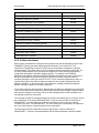
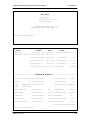
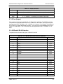
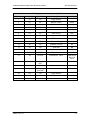
Record of Revisions
DVB3030/DVB3030L Digital Video Broadcast Modulator
Installation and Operation Manual
TM052 – Record of Revisions
Radyne ComStream Corporation is constantly improving its products and therefore the
information in this document is subject to change without prior notice. Radyne ComStream
Corporation makes no warranty of any kind with regard to this material, Including but not limited
to the implied warranties of merchantability and fitness for a particular purpose. No responsibility
for any errors or omissions that may pertain to the material herein is assumed. Radyne
ComStream Corporation makes no commitment to update nor to keep current the information
contained in this document. Radyne ComStream Corporation assumes no responsibility for use
of any circuitry other than the circuitry employed in Radyne ComStream Corporation systems
and equipment.
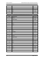
Revision
Level
Date
1
2
2.1
2.2
6-18-96
8-22-96
4-12-97
8-10-97
2.3
3.0
3.1
3.2
3.3
12-01-97
12-05-98
5-13-99
7-1-99
7-14-99
3.4
3.5
11-05-99
4-17-00
TM052 - Rev. 3.5
Reason for Change
New Release
Updated to include new symbol rate information, Update drawings
Minor operational changes; updated to include DVB3030 symbol rate data.
Changed manual to DVB3030, changed specifications and added framing
and roll off data
Added Ethernet Data, updated drawings, minor additions to remote spec.
Added 3030L-Band Data; Updated Remote Port Specification
Updated data rates, added additional interfaces, updated remote port spec.
Added Test pattern generator data
Updated Remote Port Specification; added clarifications, Added Ethernet
MIB, Appendix C.
Added last rate control data and updated DVB ASI information
Added Simple Network Management Protocol (SNMP).
v
DVB3030/DVB3030L Digital Video Broadcast Modulator
This Page is Intentionally Left Blank
vi
TM052 - Rev. 3.5
DVB3030/DVB3030L Digital Video Broadcast Modulator
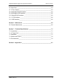
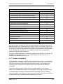
Table of Contents
Table of Contents
______________________________________________1-1
1.0 Description______________________________________________________1-1
Section 2 – Installation _______________________________________________2-1
2.0 Installation Requirements __________________________________________2-1
2.1 Unpacking ______________________________________________________2-1
2.2 Removal and Assembly ____________________________________________2-1
2.3 Mounting Considerations ___________________________________________2-2
2.4 Modulator Checkout_______________________________________________2-2
2.4.1 Initial Power-Up ________________________________________________2-2
Section 3 – Operation ________________________________________________3-1
3.0 Theory of Operation_______________________________________________3-1
3.1 DVB3030 Operation ______________________________________________3-1
3.2 Last Rate Control_________________________________________________3-1
Section 4 – User Interfaces ___________________________________________4-1
4.0 User Interfaces __________________________________________________4-1
4.1 Front Panel User Interface__________________________________________4-1
4.1.1 Front Panel LCD Display _________________________________________4-1
4.1.2 Front Panel LED Indicators________________________________________4-2
4.1.3 Front Panel Keypad _____________________________________________4-2
4.1.4 Parameter Setup _______________________________________________4-2
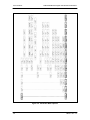
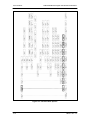
4.2 Front Panel Control Screen Menus ___________________________________4-3
4.2.1 Main Menus ___________________________________________________4-4
4.2.2 Modulator Menu Options and Parameters ____________________________4-7
4.2.3 Interface Menu Options and Parameters Menu ________________________4-9
4.2.4 Monitor Options and Parameters Menu _____________________________4-11
4.2.5 Alarms Options and Parameters Menu ______________________________4-13
4.2.6 System Options and Parameters Menu _____________________________4-16
4.2.7 Test Menu Options and Parameters _______________________________4-19
4.3 Remote Port User Interface ________________________________________4-21
4.3.1 Protocol Structure ______________________________________________4-21
TM052 - Rev. 3.5
vii
DVB3030/DVB3030L Digital Video Broadcast Modulator
4.3.2 Protocol Wrapper ______________________________________________4-21
4.3.3 Flow Control and Task Processing _________________________________4-23
4.3.4 Frame Description and Bus Handshaking ___________________________4-24
4.3.5 Global Response Operational Codes _______________________________4-24
4.3.6 Collision Avoidance ____________________________________________4-26
4.3.7 Software Compatibility __________________________________________4-27
4.3.8 RLLP Summary _______________________________________________4-28
4.3.9 DVB3030 Opcode Command Set__________________________________4-29
4.3.10 Detailed Command Descriptions _________________________________4-29
4.4 Ethernet Port User Interface _______________________________________4-39
4.4.1 SNMP Overview _______________________________________________4-40
4.4.1.1 Object Identifiers _____________________________________________4-40
4.4.2 Management Information Base____________________________________4-40
4.4.2.1 Front Panel Control ___________________________________________4-40
4.4.2.2 Terminal Control _____________________________________________4-40
4.4.2.3 SNMP Setup ________________________________________________4-42
4.4.2.4 Connecting the Terminal _______________________________________4-42
4.4.2.5 Setting the SNMP Mode _______________________________________4-43
4.4.2.6 Setting the Boot Mode _________________________________________4-43
4.4.2.7 Setting the Modem IP Address __________________________________4-43
4.4.2.8 Setting the Server IP Address ___________________________________4-43
4.4.2.9 Setting the IP Address Mask:____________________________________4-44
4.4.2.10 Setting the Community String: __________________________________4-44
4.4.2.11 Setting the Server Ethernet Address _____________________________4-44
4.5 Terminal Port User Interface _______________________________________4-48
4.5.1 DVB3030 Terminal Mode Control __________________________________4-48
4.5.2 Terminal Mode Control Screen Menus ______________________________4-48
Section 5 – Electrical Interfaces _______________________________________5-1
5.0 DVB3030 Connections ____________________________________________5-1
5.1 AC Power ______________________________________________________5-1
5.2 Ethernet Interface (I/O) ____________________________________________5-1
5.3 External Reference (Input)__________________________________________5-1
5.4 Remote Port (I/O) ________________________________________________5-1
5.5 Terminal Port (I/O) ________________________________________________5-2
viii
TM052 - Rev. 3.5
DVB3030/DVB3030L Digital Video Broadcast Modulator
Table of Contents
5.6 Alarm Port ______________________________________________________5-2
5.7 IF Port (Output) __________________________________________________5-3
5.8 ASI/Parallel RS-422 Interface _______________________________________5-3
5.9 ASI/Parallel LVDS Interface_________________________________________5-5
5.10 Serial RS-422 Interface ___________________________________________5-5
5.11 G.703 Interface _________________________________________________5-6
5.12 HSSI Interface __________________________________________________5-6
Section 6 – Maintenance _____________________________________________6-2
6.0 Periodic Maintenance _____________________________________________6-2
Section 7 – Technical Specifications ___________________________________7-1
7.0 Introduction _____________________________________________________7-1
7.1 IF Output Port ___________________________________________________7-1
7.2 Baseband ______________________________________________________7-1
7.3 Monitor and Control _______________________________________________7-2
7.4 Environmental ___________________________________________________7-2
Section 8 – Appendices ______________________________________________8-1
TM052 - Rev. 3.5
ix
DVB3030/DVB3030L Digital Video Broadcast Modulator
This Page is Intentionally Left Blank
x
TM052 - Rev. 3.5
DVB3030/DVB3030L Digital Video Broadcast Modulator
Introduction
Section 1 – Introduction
1.0 Description
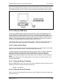
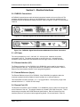
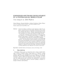
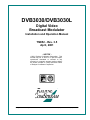
The Radyne ComStream Corporation DVB3030 and DVB3030L Digital Video Satellite
Modulators (Figure 1-1) combine full compatibility with digital video standards, and the best
features of a flexible programmable modulator at a low price. They are designed as high-speed,
frequency-agile, multi-data rate digital uplinks. The DVB3030 and DVB3030L are ideal for use in
digital video hub uplinks, and mobile Satellite Newsgathering (SNG) vehicles. Other applications
include video distribution and one-way data distribution.
The modulator offers a full frequency agile IF output from 50 MHz to 90 MHz or from 100 MHz to
180 MHz, or L-Band (from 950 MHz to 1750 MHz) in 100 Hz steps. Data rates from 1 Mbps to
78.75 Mbps (1.0 to 45.0 Msps) can be set in 1 bps increments. The modulator is fully compliant
with ETS (European Telecom Standard) 300-421, DVB and MPEG-2 standards.
The DVB3030 and DVB3030L Modulators are completely programmable from the front panel.
Menus are specifically designed for ease of use and quick online operation as well as for
changes in modulator configuration. All aspects of the modulator can also be monitored and
controlled through the RS-232/RS-485 Serial Control Port or Ethernet Port. Operating
parameters, such as data rates and IF frequencies can be readily set and changed at the front
panel or through a remote serial interface. An optional 1:1 Redundancy Control Switch (RCS11)
can be employed to give the DVB3030 and DVB3030L high systems reliability.
Note: Unless specified, DVB3030 denotes both the DVB3030 and DVB3030L units.
Figure 1-1. DVB3030/DVB3030L Digital Video Broadcast Modulator
TM052 - Rev. 3.5
1-1
Introduction
DVB3030/DVB3030L Digital Video Broadcast Modulator
This Page is Intentionally Left Blank
1-2
TM052 - Rev. 3.5
DVB3030/DVB3030L Digital Video Broadcast Modulator
Installation
Section 2 – Installation
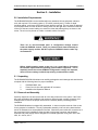
2.0 Installation Requirements
The DVB3030/DVB3030L can be installed within any standard 19-inch equipment cabinet or
rack, and requires 1 RU mounting space (1.75 inches) vertically and 17 inches of depth.
Including cabling, a minimum of 20-inches of rack depth is required. The rear panel is designed
to have power enter from the left and IF cabling enter from the right when viewed from the rear
of the unit. Data and control cabling can enter from either side although they are closer to the
center. The unit can be placed on a table or suitable surface if required.
There are no user-serviceable parts or configuration settings located
inside the DVB3030 chassis. There is a potential shock hazard internally at
the power supply module. DO NOT open the DVB3030 chassis under any
circumstances.
Before initially applying power to the unit, it is a good idea to disconnect
the transmit output from the operating ground station equipment. This is
especially true if the current DVB3030 configuration settings are unknown,
where incorrect settings could disrupt existing communications traffic.
2.1 Unpacking
The DVB3030/DVB3030L Modulator was carefully packaged to avoid damage and should arrive
complete with the following items for proper installation:
1.
2.
3.
DVB3030/3030L Unit.
Power Cord, 6-foot with applicable AC connector.
Installation and Operation Manual.
2.2 Removal and Assembly
Carefully unpack the unit and ensure that all of the above items are in the carton. If the Prime
AC power available at the installation site requires a different power cord/AC connector, then
arrangements to receive the proper device will be necessary before proceeding with the
installation.
The DVB3030 Modulator is shipped fully assembled. It does not require removal of the covers
for any purpose in installation. The only replaceable assembly in the unit is the data interface
and is not intended to be accomplished in the field. Should the power cable AC connector be of
the wrong type for the installation, either the cable or the power connector end should be
replaced. The power supply itself is designed for universal application using from 100 to 240
VAC, 50 – 60 Hz, 0.5 A.
TM052 - Rev. 3.5
2-1
Installation
DVB3030/DVB3030L Digital Video Broadcast Modulator
2.3 Mounting Considerations
When mounted in an equipment rack, adequate ventilation must be provided. The ambient
temperature in the rack should be between 10° and 35° C, and held constant for best equipment
operation. The air available to the rack should be clean and relatively dry. The DVB3030 units
may be stacked one on top of the other up to a maximum of 10 consecutive units before
providing a 1 RU space for airflow.
Do not mount the DVB3030 in an unprotected outdoor location where there is direct contact with
rain, snow, wind or sun. The DVB3030 is designed for indoor applications only.
The only tools required for rack mounting the DVB3030 is a set of four rack mounting screws and
an appropriate screwdriver. Rack mount brackets are an integral part of the cast front bezel of
the unit and are not removable.
Shielded cables with the shield terminated to the conductive backshells are required in order to
meet EMC directives. Cables with insulation flammability ratings of 94 VO or better are required
in order to meet low voltage directives.
The following interface connections should be available at the mounting location as a minimum:
1.
2.
3.
Prime AC power.
A 75-Ohm Transmit IF cable with BNC male connector.
An RS–449 data interface cable with a 37-pin male ‘D’ sub-connector.
2.4 Modulator Checkout
The following descriptions assume that the DVB3030 is installed in a suitable location with prime
AC power and supporting equipment available.
2.4.1 Initial Power-Up
Before initial powerup of the DVB3030, it is a good idea to disconnect the transmit output
from the operating ground station equipment. This is especially true if the current
modulator configuration settings are unknown, where incorrect settings could disrupt the
existing communications traffic. New units from the factory are normally shipped in a
default configuration which includes setting the transmit carrier off.
Turn the unit ‘ON’ by placing the rear panel switch (above the power entry connector) to the ‘ON’
position. Upon initial and subsequent power-ups, the DVB3030 microprocessor will test itself and
several of its components before beginning its main Monitor/Control program. These power-up
diagnostics show no results if successful. If a failure is detected, the Fault LED is illuminated.
The initial field checkout of the DVB3030 can be accomplished from the front panel or in the
Terminal Mode. The Terminal Mode has the advantage of providing full screen access to all of
the DVB3030’s parameters, but requires a separate terminal or computer running a terminal
program. The unit is placed into terminal mode by setting the option via the front panel. Set the
‘Control Mode’ parameter to ‘Terminal.’ See below for a quick introduction on the use of the
front panel and steps for entering parameters.
2-2
TM052 - Rev. 3.5
DVB3030/DVB3030L Digital Video Broadcast Modulator
TM052 - Rev. 3.5
Installation
2-3
DVB3030/DVB3030L Digital Video Broadcast Modulator
Operation
Section 3 – Operation
3.0 Theory of Operation
A digital terrestrial interface supplies the modulator with a data stream. The data stream is
synchronized if the incoming stream is framed. The data is scrambled, and FEC is added. The
data is then convolutionally encoded, punctured, then constellation mapped. The resulting I&Q
symbols are digitally filtered. The data is then converted into an analog waveform and is vector
modulated onto an RF Carrier produced from the Transmit IF Synthesizer Circuitry.
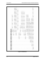
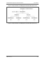
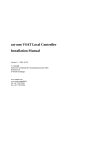
3.1 DVB3030 Operation
A block diagram of the signal flow is shown in Figure 3-1 below.
Figure 3-1. Functional Block Diagram
3.2 Last Rate Control
The mechanism used to set the Symbol Rate (SR) and Data Rate (DR) in the modems has
traditionally allowed SR to have precedence. This means that if the Modulation Format (MF),
Framing Rate (FR), or Code Rate (CR) are changed, then the SR is assumed correct, and the
DR is recalculated. Several problems have become apparent, some code related, some operator
related:
1.
The operator does not have the privilege of having DR to have precedence over SR.
This may be important for DR dependant applications, such as fixed rate interfaces or
fixed rate data multiplexers. In some cases, the iterative procedure to set an exact DR
when no calculator is available becomes very a tedious, time consuming iterative
process.
2.
The block commands for Ethernet or remote port operation have had problems because
the SR, DR, and other rate modifying commands can all be received simultaneously.
This has caused problems with precedence and ordering of calculations, and in the
timing of the multiple commands in relation to modem re-synchronization. The result
being some commands not being executed properly.
With Last Rate Control, a front panel setting allows the operator to select between Symbol, Data
and Auto modes. A status submenu under Monitor allows the operator to check the current
modem setting.
TM052 - Rev. 3.5
3-1
Operation
DVB3030/DVB3030L Digital Video Broadcast Modulator
If Symbol mode is selected, the operation of the modem should be very similar to other Radyne
products. If the Symbol Rate is entered, the Data Rate is calculated from the newly entered
Symbol Rate, the Framing mode, the QAM mode and the Convolutional mode. If the Data Rate
is entered, then the Symbol Rate is calculated instead. If the Framing mode, the QAM mode or
the Convolutional mode is entered, the Data Rate is recalculated.
If Data mode is selected, the operation should reflect the desire to have Data Rate as the
primary variable. If the Data Rate is entered, the Symbol Rate is calculated from the newly
entered Data Rate, the Framing mode, the QAM mode and the Convolutional mode. If the
Symbol Rate is entered, then the Data Rate is calculated instead. If the Framing mode, the
QAM mode or the Convolutional mode is entered, the Symbol Rate is recalculated.
If Auto mode is selected, the modem remembers if Symbol Rate or Data Rate was the last
variable entered. For example, if the Data Rate was the last variable entered, then the operator
entered Framing mode, most likely the operator would not like the Data Rate to immediately
change to a new value. Instead, by remembering that the last rate variable entered was Data
Rate, the modem would automatically assume that the operator wishes the Symbol Rate to
change instead.
3-2
TM052 - Rev. 3.5
DVB3030/DVB3030L Digital Video Broadcast Modulator
User Interfaces
Section 4 – User Interfaces
4.0 User Interfaces
There are four user interfaces available for the DVB3030. These are:
a.
b.
c.
d.
Front Panel
Remote Port
Ethernet Port
Terminal
4.1 Front Panel User Interface
The front panel of the DVB3030 allows for complete control and monitor of all DVB3030
parameters and functions via a keypad, LCD display and status LEDs.
The front panel layout is shown in Figure 4-1, showing the location and labeling of the front
panel. The front panel is divided into three functional areas: the LCD Display, the Keypad, and
the LED Indicators, each described below in Table 4-1.
Figure 4-1. DVB3030 Front Panel
Table 4-1.
Item
Number
Description
Function
1
LCD Front Panel Display
Displays DVB3030 Operating parameters and
Configuration data
2
Cursor Control Arrows
Controls the up, down, right and left motion of
the cursor in the LCD Display window
3
Numeric Keypad
Allows entry of numeric data and Clear and
Enter function keys
4
Front Panel LED Indicators
See Paragraph 3.1.5 below for an itemized
description of these LEDs
4.1.1 Front Panel LCD Display
The front panel display is a 2 line by 16-character LCD display. The display is lighted and the
brightness can be set to increase when the front panel is currently in use. The LCD display
automatically dims after a period of inactivity. The display has two distinct areas showing current
TM052 - Rev. 3.5
4-1
User Interfaces
DVB3030/DVB3030L Digital Video Broadcast Modulator
information. The upper area shows the current parameter being monitored, such as ‘Frequency’
or ‘Data Rate’. The lower line shows the current value of that parameter. The LCD display is a
single entry window into the large matrix of parameters that can be monitored and set from the
front panel.
4.1.2 Front Panel LED Indicators
Eight LEDs on the DVB3030 front panel (Refer to Table 4-2) indicate the status of the
DVB3030’s operation. The LED colors maintain a consistent meaning. Green signifies that the
indication is appropriate for normal operation, Yellow means that there is a condition not proper
for normal operation, and Red indicates a fault condition that will result in lost communications.
Table 4-2.
LED
Color
Function
Transmit On
Green
Major Alarm
Red
Minor Alarm
Yellow
Indicates a transmit warning condition exists.
Test Mode
Yellow
Indicates the modulator is involved in a current test mode
activity.
Power
Green
Indicates the DVB3030 unit is currently powered up.
Fault
Red
Event
Yellow
Indicates that a new event has been logged into the event
buffer.
Remote
Green
Indicates that the unit is set to respond to the remote control
or terminal input.
Indicates the DVB Transmitter is turned on.
Indicates that the transmit direction has failed, losing traffic.
Indicates a memory failure or power out of spec.
4.1.3 Front Panel Keypad
The front panel keypad consists of two areas: a 10-key numeric entry with 2 additional keys for
the ‘Enter’ and ‘Clear’ function. The second area is a set of ‘Arrow’ or ‘Cursor’ keys (↑
↑ ), (↓
↓ ), (→
→ ),
(←
← ), used to navigate the parameter currently being monitored or controlled. Table 4-3
describes the key functions available at the front panel.
4.1.4 Parameter Setup
The four arrow keys (↑
↑ ), (↓
↓ ), (→
→ ), (←
← ), to the right of the LCD display are used to navigate the
menu tree and select the parameter to be set. After arriving at a parameter that needs to be
modified, depress <ENTER>. The first space of the modifiable parameter highlights (blinks) and
is ready for a new parameter to be entered. After entering the new parameter using the keypad
(Refer to Figure 4-3), depress <ENTER> to lock in the new parameter. If a change needs to be
made prior to pressing <ENTER>, depress <CLEAR> and the display defaults back to the
original parameter. Depress <ENTER> again and re-enter the new parameters followed by
<ENTER>.
Following a valid input, the DVB3030 will place the new setting into the nonvolatile EEPROM
making it available immediately and is available the next time the unit is powered-up.
4-2
TM052 - Rev. 3.5
DVB3030/DVB3030L Digital Video Broadcast Modulator
User Interfaces
Table 4-3.
Edit Mode Key Functions (Front Panel Only)
Parameter
Type
Fixed Point
Decimal
0–9
↑
Changes Digit Toggles ±
(If Signed)
↓
←
→
‘Clear’ &
←
‘Clear’ &
→
Toggles ±
(If Signed)
Moves
Cursor 1
Position
Left
Moves
Cursor 1
Position
Right
N/A
N/A
Moves
Cursor 1
Position
Left
Moves
Cursor 1
Position
Right
N/A
N/A
Unsigned Changes Digit Increments Decrements
Hexadecimal
Digit Value Digit Value
Enumerated
N/A
Previous
Value in
List
Next
Value in
List
N/A
N/A
N/A
N/A
Date/ Time
Changes Digit
N/A
N/A
Moves
Cursor 1
Position
Left
Moves
Cursor 1
Position
Right
N/A
N/A
IP Address
Changes Digit Increments Decrements
Digit Value Digit Value
Moves
Cursor 1
Position
Left
Moves
Cursor 1
Position
Right
N/A
N/A
Moves
Cursor 1
Position
Left
Moves
Cursor 1
Position
Right
Clears to
Left of
Cursor
Inclusive
Clears to
Right of
Cursor
Inclusive
Text Strings
Changes
Character
Increments Decrements
Character
Character
Value
Value
Figure 4-2. Entering New Parameters
4.2 Front Panel Control Screen Menus
The complete set of DVB3030 Front Panel Control Screens is shown below in Figure 4-3.
TM052 - Rev. 3.5
4-3
User Interfaces
DVB3030/DVB3030L Digital Video Broadcast Modulator
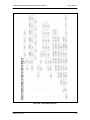
4.2.1 Main Menus
There are six main menus available from the Front Panel of the DVB3030/DVB3030L (Refer to
Figure 4-4). These include:
1.
Modulator:
2.
Interface:
3.
Monitor:
4.
Alarms:
5.
System:
6.
Test:
4-4
TM052 - Rev. 3.5
DVB3030/DVB3030L Digital Video Broadcast Modulator
User Interfaces
Figure 4-3. Front Panel Control Screens
TM052 - Rev. 3.5
4-5
User Interfaces
DVB3030/DVB3030L Digital Video Broadcast Modulator
Figure 4-4. Main Menus
4-6
TM052 - Rev. 3.5
DVB3030/DVB3030L Digital Video Broadcast Modulator
User Interfaces
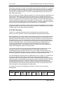
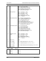
4.2.2 Modulator Menu Options and Parameters
There are 12 Modulator Screens available (Refer to Figure 4-5). These include:
1.
Frequency:
IF Carrier Frequency
Enter in 100 Hz increments from 50 - 90 or 100 - 180
MHz. L-Band (950-1525 MHz) is optional.
2.
Power:
Transmit Output Power
Enter in 0.1 dBm increments from -20.0 to 5.0 dBm.
3.
Carrier:
{On, Off}
Transmitter Power On/Off Control.
4.
Spectrum Inv:
{Normal, Inverted}
Modulated output spectrum inversion.
5.
Modulation:
{QPSK, BPSK}
Modulation Type.
6.
Symbol Rate:
Output Symbol Rate
Enter in 1 SPS increments from 1,000,000 to
45,000,000 SPS.
7.
Data Rate:
Terrestrial Data Rate
Enter in 1 BPS increments from 1,000,000 to
78,750,000 BPS.
8.
Clock Invert:
{Normal, Inverted}
Inverts the terrestrial data clock.
9.
Data Invert:
{Normal, Inverted}
Inverts the terrestrial data stream.
10.
Conv Enc:
{None, VIT1/2, VIT2/3, VIT3/4, VIT5/6, VIT6/7, VIT7/8}
Sets the convolutional encoder rate.
Note: Changing FEC rate will leave Symbol rate constant while changing data rate for
new overhead. If previous data rate is desired, it must be reentered after FEC rate change.
11.
Roll Off:
{0.35, 0.20}
Changes the Spectrum Roll Off.
12.
Last Rate Control:
{SYMBOL, DATA, AUTO}
Selects rate precedence, See Last Rate Control Notes.
TM052 - Rev. 3.5
4-7
User Interfaces
DVB3030/DVB3030L Digital Video Broadcast Modulator
Figure 4-5. Modulator Menu Options
4-8
TM052 - Rev. 3.5
DVB3030/DVB3030L Digital Video Broadcast Modulator
User Interfaces
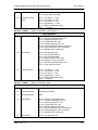
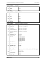
4.2.3 Interface Menu Options and Parameters Menu
There are eight Interface Screens available (Refer to Figure 4-6). These include:.
1.
Type:
{Serial, Parallel, ASI, G.703, HSSI}
Enter the terrestrial interface type.
Note: Interface types that have not been ordered may not be selected.
2.
Clock Invert:
{Normal, Inverted}
Inverts the terrestrial data clock. This is the same as
Clock. Invert under the Modulator Menu.
3.
Data Invert:
{Normal, Inverted}
Inverts the terrestrial data stream. This is the same as
Data Invert under the Modulator Menu.
4.
Data Clock Select:
{SCT, SCTE}
SCT: Data clock is supplied by DVB modulator
internally.
SCTE: Data clock is supplied by user equipment to
DVB modulator.
Note: The Transmit Clock (SCT) supplied by the DVB3030 is always Output. Normally,
this clock is used to clock the data out of the data source and then return it to the SCTE
pins of J9. The DVB3030 is then set to SCTE mode eliminating any possible clock skew.
Alternately, the data source can generate the SCTE clock internally and the SCT signal
can be ignored. If SCT mode is selected, the Modulator data clock will not be locked to
the incoming data stream. This mode is NOT recommended except for testing or fault
backup.
5.
EXT CLK OUT:
{SCT, SCTE, NONE}
Selects the source of clock output from the G.703
Interface. For Serial or Parallel, the selection is ‘SCT’
and for ASI, it is ‘NONE.’
6.
Freq Ref Src:
{Internal, External}
Selects the frequency reference source.
7.
Ext Ref Freq:
External Reference Frequency: Enter the external
reference frequency in 8 KHz steps from 1 MHz to 10
MHz.
8.
Framing Mode:
{None, 188, 204}
Selects the number of bytes per incoming data frame, or
unframed data.
Note: ‘None’ is unframed data
TM052 - Rev. 3.5
4-9
User Interfaces
DVB3030/DVB3030L Digital Video Broadcast Modulator
Figure 4-6. Interface Menu Options
4-10
TM052 - Rev. 3.5
DVB3030/DVB3030L Digital Video Broadcast Modulator
User Interfaces
4.2.4 Monitor Options and Parameters Menu
There are six Monitor Screens available (Refer to Figure 4-7). These include:
1.
Event Buff:
Display/Clear logged events and faults.
2.
Clear Events:
Clear all logged events and faults from the event buffer.
3.
+5 Volt:
Display the currently measured +5 VDC power supply.
4.
+12 Volt:
Display the currently measured +12 VDC power supply.
5.
-12 Volt:
Display the currently measured -12 VDC power supply.
6.
Last Rate:
{SYMBOL, DATA}
Shows modulator rate precedence. See Last Rate
Control notes.
TM052 - Rev. 3.5
4-11
User Interfaces
DVB3030/DVB3030L Digital Video Broadcast Modulator
Figure 4-7. Monitor Menu Options
4-12
TM052 - Rev. 3.5
DVB3030/DVB3030L Digital Video Broadcast Modulator
User Interfaces
4.2.5 Alarms Options and Parameters Menu
The Alarms Screens are shown in Figure 4-8. These include:
Current Alarm (Menu):
Displays Current Alarm Status.
Major TX (Menu)
Tx Power Mask:
View or change the masking for Tx Power
Alarm.
IntrCfg Mask:
View or change the masking for Interleaver
Configuration Alarm.
ConvCfg Mask:
View or change the masking for Convolutional
Encoder Alarm.
TxOSClk Mask:
View or change the masking for Transmit
Oscillator Alarm.
TxSynth Mask:
View or change the masking for Transmit
Synthesizer Alarm.
ExtRef Mask:
View or change the masking for External
Reference PLL Alarm.
Minor TX (Menu)
TerrClk Mask:
View or change the masking for Terrestrial
Clock Present Alarm.
TerrDat Mask:
View or change the masking for Terrestrial Data
Present Alarm.
FrmSync Mask:
View or change the masking for DVB Frame
Synchronization Alarm.
Count Mask:
View or change the masking for DVB Interleaver
Count Error Alarm.
FIFO Mask:
View or change the masking for Reed-Solomon
FIFO Empty/Full Alarm.
View or change the masking for Internal Clock
Present Alarm.
IntClk Mask:
Fault (Menu)
TM052 - Rev. 3.5
Temp. Mask:
View or change the masking for Temperature
Fault.
RAM/ROM Mask:
View or change the masking for ROM/RAM
Error Fault.
+ 5V Mask:
View or change the masking for +5 VDC Supply
Fault.
4-13
User Interfaces
DVB3030/DVB3030L Digital Video Broadcast Modulator
+12V Mask:
View or change the masking for +12 VDC
Supply Fault.
-12V Mask:
View or change the masking for -12 VDC Supply
Fault.
Latched Alarm (Menu):
4-14
This menu duplicates the Current Alarm Menu,
but displays Latched Alarms instead of Current
Alarms.
TM052 - Rev. 3.5
DVB3030/DVB3030L Digital Video Broadcast Modulator
User Interfaces
Figure 4-8. Alarms Menu Options
TM052 - Rev. 3.5
4-15
User Interfaces
DVB3030/DVB3030L Digital Video Broadcast Modulator
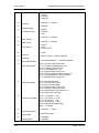
4.2.6 System Options and Parameters Menu
The System Screens are shown in Figure 4-9. These include:
1.
General (menu)
Control Mode:
{FT Panel, Computer, Terminal}
Enter the control mode for:
FT Panel (Front panel commands accepted), or
Terminal (Terminal commands accepted), or
Computer (Computer M&C commands
accepted).
Address:
Multi-Drop Address: Enter the address for
computer control from 32 to 255.
Date:
Enter the date in YY/MM/DD format.
Time:
Enter the time in HH:MM:SS format.
Bklt Level:
{Low, Mid, High, ON}
Enter the backlight level intensity. ‘ON’ will
disable the timeout and backlight will remain on.
Bklt Timeout:
Enter the timeout for the backlight in 1 second
intervals from 0 to 99 seconds.
Key Click:
{Off, On}
Set Key Click.
Baud Rate:
{2400, 9600, 19200}
Remote port baud rate for Terminal and
Computer Mode.
Note: When changing the Baud Rate, power must be cycled for the new rate to take
effect.
4-16
Stop Bits (N/A):
Number of Stop Bits is always 1 for Remote
Port.
Parity (N/A):
Parity is always None for Remote Port.
Terminal Emulation:
{ADDS VP, VT100, WYSE 50}
Set Remote Port Terminal Mode Emulation.
Version #.#:
Displays software revision number.
INT CPLD:
Displays Interface CPLD Revision Number.
INT FPGA:
Displays Interface FPGA Revision Number.
Version #.#:
Displays Convolutional Encoder Revision
Number
TM052 - Rev. 3.5
DVB3030/DVB3030L Digital Video Broadcast Modulator
User Interfaces
Options (menu)
TM052 - Rev. 3.5
SNMP:
{Normal, Test}
Modem E Addr:
Enter the Modem Ethernet Address
Modem IP Addr:
Enter the Modem IP Address
Server E Addr:
Enter the Server Ethernet Address
Server IP Addr:
Enter the Server IP Address
Router IP Addr:
Enter the Router IP Address
IP Addr Mask:
Enter the IP Addr Mask
4-17
User Interfaces
DVB3030/DVB3030L Digital Video Broadcast Modulator
Figure 4-9. System Menu Options
4-18
TM052 - Rev. 3.5
DVB3030/DVB3030L Digital Video Broadcast Modulator
User Interfaces
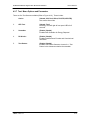
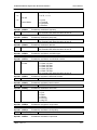
4.2.7 Test Menu Options and Parameters
There are five Test Screens available (Refer to Figure 4-10). These include:
Carrier:
{Normal, CW, Dual, Offset, POS.FIR, NEG.FIR}
Sets carrier test modes.
2.
LED Test:
{Normal, Test}
Selecting ‘Test’ will light all front panel LEDs for 5
seconds.
3.
Scrambler:
{Enable, Disable}
Enables DVB Scrambler for Energy Dispersal
4.
RS & Intlvr:
{Enable, Disable}
Enables Reed-Solomon Encoder and Convolutional
Interleaver
5.
Test Pattern:
{Enable, Disable}
Enables Test Pattern Generator. Inserts 215-1 Test
Pattern in the data stream before the scrambler.
TM052 - Rev. 3.5
4-19
User Interfaces
DVB3030/DVB3030L Digital Video Broadcast Modulator
Figure 4-10. Test Menu Options
4-20
TM052 - Rev. 3.5
DVB3030/DVB3030L Digital Video Broadcast Modulator
User Interfaces
4.3 Remote Port User Interface
The Remote Port of the DVB3030 allows for complete control and monitor functions via an
RS-485 Serial Interface.
Control and status messages are conveyed between the DVB3030 and the subsidiary modems
and the host computer using packetized message blocks in accordance with a proprietary
communications specification. This communication is handled by the Radyne Link Level
Protocol (RLLP), which serves as a protocol ‘wrapper’ for the M&C data.
Complete information on monitor and control software is contained in the following sections.
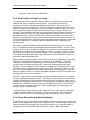
4.3.1 Protocol Structure
The Communications Specification (COMMSPEC) defines the interaction of computer resident
Monitor and Control software used in satellite earth station equipment such as modems,
redundancy switches, multiplexers, and other ancillary support gear. Communication is bidirectional, and is normally established on one or more full-duplex 9600 baud multi-drop control
buses that conform to EIA Standard RS-485.
Each piece of earth station equipment on a control bus has a unique physical address, which is
assigned during station setup/configuration or prior to shipment. Valid decimal addresses on one
control bus range from 032 through 255 for a total of up to 224 devices per bus. Address 255 of
each control bus is usually reserved for the M&C computer.
4.3.2 Protocol Wrapper
The Radyne COMMSPEC is byte-oriented, with the Least Significant Bit (LSB) issued first. Each
data byte is conveyed as mark/space information with two marks comprising the stop data.
When the last byte of data is transmitted, a hold comprises one steady mark (the last stop bit).
To begin or resume data transfer, a space (00h) substitutes this mark. This handling scheme is
controlled by the hardware and is transparent to the user. A pictorial representation of the data
and its surrounding overhead may be shown as follows:
S1
S2
B0
B1
B2
B3
B4
B5
B6
B7
S1
S2,
etc
The stop bits, S1 and S2, are each a mark. Data flow remains in a hold mode until S2 is
replaced by a space. If S2 is followed by a space, it is considered a start bit for the data byte
and not part of the actual data (B0 - B 7).
The COMMSPEC developed for use with the Radyne Link Level Protocol (RLLP) organizes the
actual monitor and control data within a shell, or "protocol wrapper", that surrounds the data.
The format and structure of the COMMSPEC message exchanges are described herein.
Decimal numbers have no suffix; hexadecimal numbers end with a lower case h suffix and
binary values have a lower case b suffix. Thus, 22 = 16h = 000010110b. The principal elements
of a data frame, in order of occurrence, are summarized as follows:
<SYN> - the message format header character, or ASCII sync character, that defines the
beginning of a message. The <SYN> character value is always 16h.
<BYTE COUNT> - the Byte Count is the number of bytes in the <DATA> field, ranging from 0
through TBD. This field is 2 bytes long for the DVB3030 protocol.
TM052 - Rev. 3.5
4-21
User Interfaces
DVB3030/DVB3030L Digital Video Broadcast Modulator
<SOURCE ID> - the Source Identifier defines the multi-drop address origin. Note that all nodes
on a given control bus have an unique address that must be defined.
<DESTINATION ID> - The Destination Identifier serves as a pointer to the multi-drop destination
device that indicates where the message is to be sent.
<FRAME SEQUENCE NUMBER> - The FSN is a tag with a value from 0 through 255 that is
sent with each message. It assures sequential information framing and correct equipment
acknowledgment and data transfers.
<OPCODE> - The Operation Code field contains a number that identifies the message type
associated with the data that follows it. Equipment under MCS control recognizes this byte via
firmware identification and subsequently steers the DATA accordingly to perform a specific
function or series of functions. Acknowledgment and error codes are returned in this field. This
field is 2 Bytes for the DVB3030 protocol.
<...DATA...> - The Data field contains the binary, bi-directional data bytes associated with the
<OPCODE>. The number of data bytes in this field is indicated by the <BYTE COUNT> value.
<CHECKSUM> - The checksum is the modulo 256 sum of all preceding message bytes,
excluding the <SYN> character. The checksum determines the presence or absence of errors
within the message. In a message block with the following parameters, the checksum is
computed as shown below in Table B-1.
Table B-1. Checksum Calculation Example
Byte Field
Data Content
Running Checksum
<BYTE COUNT> (Byte 1)
00h = 00000000b
00000000b
<BYTE COUNT> (Byte 2)
02h = 00000010b
00000010b
<SOURCEID>
F0h = 11110000b
11110010b
<DESTINATION ID>
2Ah = 00101010b
00011100b
<FSN>
09h = 00001001b
<OPCODE> (Byte 1)
00h = 00000000b
< 00100101b
00101000b
<OPCODE>
03h = 00000011b
00101000b
<DATA> (Byte 1)
DFh = 11011111b
00000111b
<DATA> (Byte 2)
FEh = 11111110b
00000101b
Thus, the checksum is 00000101b; which is 05h or 5 decimal. Alternative methods of
calculating the checksum for the same message frame are:
00h + 02h + F0h + 2Ah + 09h + 00h + 03h + DFh + FEh = 305h.
Since the only concern is the modulo 256 (modulo 100h) equivalent (values that can be
represented by a single 8-bit byte), the checksum is 05h.
For a decimal checksum calculation, the equivalent values for each information field are:
0 + 2 + 240 + 42 + 9 + 0 + 3 + 223 + 254 = 773;
773/256 = 3 with a remainder of 5. This remainder is the checksum for the frame.
4-22
TM052 - Rev. 3.5
DVB3030/DVB3030L Digital Video Broadcast Modulator
User Interfaces
5 (decimal) = 05h = 0101b = <CHECKSUM>
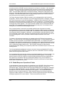
4.3.3 Flow Control and Task Processing
The original packet sender (the M&C computer) relies on accurate timeout information with
regard to each piece of equipment under its control. This provides for efficient bus
communication without unnecessary handshake overhead timing. One critical value is
designated the Inter-Frame Space (FS). The Inter-Frame Space provides a period of time in
which the packet receiver and medium (control bus and M&C computer interface) fully recover
from the packet transmission/reception process and the receiver is ready to accept a new
message. The programmed value of the Inter-Frame Space should be greater than the sum of
the "turnaround time" and the round-trip (sender/receiver/bus) propagation time, including
handshake overhead. The term "turnaround time" refers to the amount of time required for a
receiver to be re-enabled and ready to receive a packet after having just received a packet. In
flow control programming, the Inter-Frame Space may be determined empirically in accord with
the system configuration, or calculated based on established maximum equipment task
processing times.
Each piece of supported equipment on the control bus executes a Radyne Link Level Task
(RLLT) in accordance with its internal hardware and fixed program structure. In a flow control
example, the RLLT issues an internal "message in" system call to invoke an I/0 wait condition
that persists until the task receives a command from the M & C computer. The RLLT has the
option of setting a timeout on the incoming message. Thus, if the equipment does not receive
an information/command packet within a given time period, the associated RLLT exits the I/0
wait state and takes appropriate action.
Radyne equipment is logically linked to the control bus via an Internal Input/Output Processing
Task (IOPT) to handle frame sequencing, error checking, and handshaking. The IOPT is
essentially a link between the equipment RLLT and the control bus. Each time the M&C
computer sends a message packet, the IOPT receives the message and performs error
checking. If errors are absent, the IOPT passes the message to the equipment's RLLT. If the
IOPT detects errors, it appends error messages to the packet. Whenever an error occurs, the
IOPT notes it and discards the message; but it keeps track of the incoming packet. Once the
packet is complete, the IOPT conveys the appropriate message to the RLLT and invokes an I/0
wait state (wait for next <SYN> character).
If the RLLT receives the packetized message from the sender before it times out, it checks for
any error messages appended by the IOPT. In the absence of errors, the RLLT processes the
received command sent via the transmitted packet and issues a "message out" system call to
ultimately acknowledge the received packet. This call generates the response packet conveyed
to the sender. If the IOPT sensed errors in the received packet and an RLLT timeout has not
occurred, the RLLT causes the equipment to issue the appropriate error message(s) in the
pending equipment response frame.
To maintain frame synchronization, the IOPT keeps track of error-laden packets and packets
intended for other equipment for the duration of each received packet. Once the packet is
complete, the IOPT invokes an I/0 wait state and searches for the next <SYN> character.
4.3.4 Frame Description and Bus Handshaking
In a Monitor and Control environment, every message frame on a control bus port executes as a
packet in a loop beginning with a wait-for-SYN-character mode. The remaining message format
header information is then loaded, either by the M&C computer or by a subordinate piece of
equipment (such as the DVB3030) requesting access to the bus. Data is processed in
TM052 - Rev. 3.5
4-23
User Interfaces
DVB3030/DVB3030L Digital Video Broadcast Modulator
accordance with the OPCODE, and the checksum for the frame is calculated. If the anticipated
checksum does not match then a checksum error response is returned to the message frame
originator. The entire message frame is discarded and the wait-for-SYN mode goes back into
effect. If the OPCODE resides within a command message, it defines the class of action that
denotes an instruction that is specific to the device type, and is a prefix to the DATA field if data
is required. If the OPCODE resides within a query message packet, then it defines the query
code, and can serve as a prefix to query code DATA.
The Frame Sequence Number (FSN) is included in every message packet, and increments
sequentially. When the M & C computer or bus-linked equipment initiates a message, it assigns
the FSN as a tag for error control and handshaking. A different FSN is produced for each new
message from the FSN originator to a specific device on the control bus. If a command packet
is sent and not received at its intended destination, then an appropriate response message is not
received by the packet originator. The original command packet is then re-transmitted with the
same FSN. If the repeated message is received correctly at this point, it is considered a new
message and is executed and acknowledged as such.
If the command packet is received at its intended destination but the response message
(acknowledgment) is lost, then the message originator (usually the M&C computer) re-transmits
the original command packet with the same FSN. The destination device detects the same FSN
and recognizes that the message is a duplicate, so the associated commands within the packet
are not executed a second time. However, the response packet is again sent back to the source
as an acknowledgment in order to preclude undesired multiple executions of the same
command.
To reiterate, valid equipment responses to a message require the FSN tag in the command
packet. This serves as part of the handshake/acknowledge routine. If a valid response message
is absent, then the command is re-transmitted with the same FSN. For a repeat of the same
command involving iterative processes (such as increasing or decreasing transmit power level of
a DVB3030), the FSN is incremented after each message packet. When the FSN value reaches
255, it overflows and begins again at zero. The FSN tag is a powerful tool that assures
sequential information framing, and is especially useful where commands require more than one
message packet.
The full handshake/acknowledgment involves a reversal of source and destination ID codes in
the next message frame, followed by a response code in the <OPCODE> field of the message
packet from the equipment under control.
If a command packet is sent and not received at its intended destination, a timeout condition can
occur because a response message is not received by the packet originator. On receiving
devices slaved to an M & C computer, the timeout delay parameters may be programmed into
the equipment in accordance with site requirements by Radyne Corp. prior to shipment, or
altered by qualified personnel. The FSN handshake routines must account for timeout delays
and be able to introduce them as well.
4.3.5 Global Response Operational Codes
In acknowledgment (response) packets, the operational code <OPCODE> field of the message
packet is set to 0 by the receiving devices when the message intended for the device is
evaluated as valid. The device that receives the valid message then exchanges the <SOURCE
ID> with the <DESTINATION ID>, sets the <OPCODE> to zero in order to indicate that a good
message was received, and returns the packet to the originator. This "GOOD MESSAGE"
Opcode is one of nine global responses. Global response Opcodes are common responses,
issued to the M&C computer or to another device, that can originate from and are interpreted by
all Radyne equipment in the same manner. These are summarized as follows:
4-24
TM052 - Rev. 3.5
DVB3030/DVB3030L Digital Video Broadcast Modulator
User Interfaces
Table B-2. Response Opcodes
Response Opcode Description
Opcode
Good Message
00h
Bad Parameter
FFh
Bad Opcode
FEh
Bad Checksum
FDh
Command Not Allowed in LOCAL Mode
FCh
Command Not Allowed in AUTO Mode
FBh
Bad Destination
FAh
Unable to Process Command
F9h
Packet Too Long
F8h
The following response error codes are specific to the DVB3030:
DVB3030 Response Error Codes
Description
Opcode
MPARM_FREQUENCY_ERROR
0x0401
MPARM_STRAP_ERROR
0x0402
MPARM_DATARATE_ERROR
0x0404
MPARM_EXTREFERENCE_ERROR
0x0406
MPARM_EXTREFSOURCE_ERROR
0x0407
MPARM_MODULATIONTYPE_ERROR
0x0408
MPARM_CONVENCODER_ERROR
0x0409
MPARM_REEDSOLOMON_ERROR
0x040A
MPARM_SCRAMBLERCONTROL_ERROR
0x040B
MPARM_SCRAMBLERTYPE_ERROR
0x040C
MPARM_IBSSCRAMBLER_ERROR
0x040D
MPARM_V35SCRAMBLER_ERROR
0x040E
MPARM_DIFFERENTIALENCODER_ERROR
0x040F
MPARM_XMITPOWERLEVEL_ERROR
0x0410
MPARM_CARRIERCONTROL_ERROR
0x0411
MPARM_CARRIERSELECTION_ERROR
0x0412
MPARM_SPECTRUM_ERROR
0x0413
MPARM_OPERATINGMODE_ERROR
0x0414
MPARM_CLOCKCONTROL_ERROR
0x0417
MPARM_CLOCKPOLARITY_ERROR
0x0418
TM052 - Rev. 3.5
4-25
User Interfaces
DVB3030/DVB3030L Digital Video Broadcast Modulator
MPARM_FRAMING_ERROR
0x0419
MPARM_SCTSOURCE_ERROR
0x041B
MPARM_CIRCUITID_ERROR
0x0423
MPARM_INTERFACETYPE_ERROR
0x0429
MPARM_INTERFACENOTPRESENT_ERROR
0x042A
MPARM_INTERFACECOMMUNICATION_ERROR
0x042B
MPARM_SYMBOLRATE_ERROR
0x042C
MPARM_NOTIMPLEMENTED_ERROR
0x042D
MPARM_DATAPOLARITY_ERROR
0x042E
MPARM_INTERFACE_ERROR
0x042F
MPARM_SYMBOLRATEMODE_ERROR
0x0430
MPARM_FRAMINGMODE_ERROR
0x0450
MPARM_ROLLOFF_ERROR
0x0451
MDPARM_TIME_ERROR
0x0A01
MDPARM_DATE_ERROR
0x0A02
4.3.6 Collision Avoidance
When properly implemented, the physical and logical devices and ID addressing scheme of the
COMMSPEC normally precludes message packet contention on the control bus. The
importance of designating unique IDs for each device during station configuration cannot be
overemphasized. One pitfall, which is often overlooked, concerns multi-drop override IDs. All
too often, multiple devices of the same type are assigned in a direct-linked ("single-thread")
configuration accessible to the M&C computer directly. For example, if two DVB3030
Modulators with different addresses (DESTINATION IDs) are linked to the same control bus at
the same hierarchical level, both will attempt to respond to the M&C computer when the
computer generates a multi-drop override ID of 23. If their actual setup parameters, status, or
internal timing differs, they will both attempt to respond to the override simultaneously with
different information, or asynchronously in their respective message packets and response
packets, causing a collision on the serial control bus.
To preclude control bus data contention, different IDs must always be assigned to the equipment.
If two or more devices are configured for direct-linked operation, then the M&C computer and all
other devices configured in the same manner must be programmed to inhibit broadcast of the
corresponding multi-drop override ID.
The multi-drop override ID is always accepted by devices of the same type on a common control
bus, independent of the actual DESTINATION ID. These override IDs with the exception of
“BROADCAST” are responded to by all directly-linked devices of the same type causing
contention on the bus. The “BROADCAST” ID, on the other hand, is accepted by all equipment
but none of them returns a response packet to the remote M&C.
The following multi-drop override IDs are device-type specific, with the exception of
"BROADCAST". These are summarized below with ID values expressed in decimal notation:
4-26
TM052 - Rev. 3.5
DVB3030/DVB3030L Digital Video Broadcast Modulator
User Interfaces
Table B-3. Broadcast IDs
DIRECTLY-ADDRESSED EQUIPMENT
MULTI-DROP OVERRIDE ID
Broadcast (all directly-linked devices)
00
DMD-3000/4000, 4500 or 5000 Mod Section, DMD15
01
DMD-3000/4000, 4500 or 5000 Demod Section, DMD15
02
RCU-340 1:1 Switch
03
RCS-780 1:N Switch
04
RMUX-340 Cross-Connect Multiplexer
05
CDS-780 Clock Distribution System
05
SOM-340 Second Order Multiplexer
07
DMD-4500/5000 Modulator Section
08
DMD-4500/5000 Demodulator Section
09
RCU-5000 M:N Switch
10
DMD15 Modulator
20
DMD15 Demodulator
21
DMD15 Modem
22
DVB3030 Video Modulator
23
Reserved for future equipment types
24 - 31
Note that multi-drop override ID 01 can be used interchangeably to broadcast a message to a
DMD-3000/4000 modem, a DMD-4500/5000, a DMD15 modem, or a DVB3030. Radyne Corp.
recommends that the multi-drop override IDs be issued only during system configuration as a
bus test tool by experienced programmers, and that they not be included in run-time software. It
is also advantageous to consider the use of multiple bus systems where warranted by a
moderate to large equipment complement.
Therefore, if a DMD15 Modulator is queried for its equipment type identifier, it will return a "20"
and DMD15 Demodulator will return a "21". A DMD15 Modem will also return an "22". A
DVB3030 Video Modulator will return a “23.”
4.3.7 Software Compatibility
The COMMSPEC, operating in conjunction within the RLLP shell, provides for full forward and
backward software compatibility independent of the software version in use. New features are
appended to the end of the DATA field without OPCODE changes. Older software simply
discards the data as extraneous information without functional impairment for backward
compatibility.
If new device-resident or M&C software receives a message related to an old software
version, new information and processes are not damaged or affected by the omission of data.
The implementation of forward and backward software compatibility often, but not always,
requires the addition of new Opcodes. Each new function requires a new Opcode assignment if
forward and backward compatibility cannot be attained by other means.
TM052 - Rev. 3.5
4-27
User Interfaces
DVB3030/DVB3030L Digital Video Broadcast Modulator
When Radyne equipment is queried for information (Query Mod, Query Demod, etc.) it responds
by sending back two blocks of data; a non-volatile section (parameters that can be modified by
the user) and a volatile section (status information). It also returns a count value that indicates
how large the non-volatile section is. This count is used by M&C developers to index into the
start of the volatile section.
When new features are added to Radyne equipment, the control parameters are appended to the
end of the non-volatile section, and status of the features, if any, are added at the end of the
volatile section. If a remote M&C queries two pieces of Radyne equipment with different revision
software, they might respond with two different sized packets. The remote M&C MUST make use
of the non-volatile count value to index to the start of the volatile section. If the remote M&C is
not aware of the newly added features to the Radyne product, it should disregard the parameters
at the end of the non-volatile section and index to the start of the volatile section.
If packets are handled in this fashion, there will also be backward-compatibility between Radyne
equipment and M&C systems. Remote M&C systems need not be modified every time a feature
is added unless the user needs access to that feature.
4.3.8 RLLP Summary
The RLLP is a simple send-and-wait protocol that automatically re-transmits a packet
whenever an error is detected, or when an acknowledgment (response) packet is absent.
During transmission, the protocol wrapper surrounds the actual data to form information packets.
Each transmitted packet is subject to time out and frame sequence control parameters, after
which the packet sender waits for the receiver to convey its response. Once a receiver verifies
that a packet sent to it is in the correct sequence relative to the previously received packet, it
computes a local checksum on all information within the packet excluding the <SYN> character
and the <CHECKSUM> fields. If this checksum matches the packet <CHECKSUM>, the
receiver processes the packet and responds to the packet sender with a valid response
(acknowledgment) packet. If the checksum values do not match, the receiver replies with a
negative acknowledgment (NAK) in its response frame.
The response packet is therefore either an acknowledgment that the message was received
correctly, or some form of a packetized NAK frame. If the sender receives a valid
acknowledgment (response) packet from the receiver, the <FSN> increments and the next
packet is transmitted as required by the sender. However, if a NAK response packet is returned
the sender re-transmits the original information packet with the same embedded <FSN>.
If an acknowledgment (response) packet or a NAK packet is lost, corrupted, or not issued due to
an error and is thereby not returned to the sender, the sender re-transmits the original
information packet; but with the same <FSN>. When the intended receiver detects a duplicate
packet, the packet is acknowledged with a response packet and internally discarded to preclude
undesired repetitive executions. If the M&C computer sends a command packet and the
corresponding response packet is lost due to a system or internal error, the computer times out
and re-transmits the same command packet with the same <FSN> to the same receiver and
waits once again for an acknowledgment or a NAK packet.
To reiterate, the format of the message block is shown in Table 4, Link Level Protocol
Message Block.
Table 4. Link Level Protocol Message Block
SYNC
4-28
COUNT
SRC
ADDR
DEST
ADDR
FSN
OP
CODE
DATA
BYTES
CHECKSUM
TM052 - Rev. 3.5
DVB3030/DVB3030L Digital Video Broadcast Modulator
User Interfaces
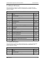
4.3.9 DVB3030 Opcode Command Set
Command
Opcode
Query Mod All
2400h
Query Identification
2403h
Query Modem Control Mode
2404h
Query Mod Latched Alarms
2405h
Query Mod Current Alarms
2408h
Query Mod Status
240Bh
Query Time
240Eh
Query Date
240Fh
Query Time and Date
2410h
Command Modem Control Mode
2600h
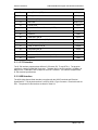
Command Mod Configuration
Command Mod Single Parameter:
Frequency
Strap Code
Data Rate
Modulation Type
Convolutional Encoder
Differential Encoder
Carrier Control
Carrier Test
Clock Control
Clock Polarity
Transmit Power Level
Reed-Solomon
Spectrum
Operating Mode
Scrambler Control
Scrambler Type
Framing
External Reference Source
External Reference
Data Polarity
Interface
Command Clear Latched Alarms
2601h
2602h
2603h
2604h
2606h
2607h
2608h
2609h
260Ah
260Bh
260Ch
260Fh
2610h
2611h
2612h
2613h
2614h
2615h
2616h
261Bh
2620h
2621h
2A19h
Command Set Time
2C04h
Command Set Date
2C05h
Command Set Time and Date
2C06h
4.3.10 Detailed Command Descriptions
Opcode: <2400h>
TM052 - Rev. 3.5
(Query Mod All) Query a modulator's configuration and status
4-29
User Interfaces
DVB3030/DVB3030L Digital Video Broadcast Modulator
Query Response
<1>
Number of nonvol
bytes
<4>
IF Frequency
Binary value, 1 Hz steps
<2>
Strap Code
Binary value, 0 through 65535
<4>
Data Rate
Binary value, 1 bps steps
<4>
External Reference
Binary value, 1 Hz steps
<1>
Freq. Reference
Source
0 = Internal, 1 = External
<1>
Modulation Type
0 = QPSK
<1>
Convolutional
Encoder
0 = None, 1 = Viterbi 1/2 Rate, 2 = Viterbi 2/3 Rate, 3 = Viterbi
3/4 Rate, 4 = Viterbi 5/6 Rate, 5 = Viterbi 7/8 Rate
<1>
Reed-Solomon
1 = Enable
<1>
Scrambler Control
1 = Enable
<1>
Scrambler Type
0 = DVB
<1>
Differential Encoder
0 = Off
<2>
Transmit Power
Level
Signed value. +50 to -200 (+5.0 to -20.0 dBm implied decimal
point)
0 = Off, 1 = On
<1>
Carrier Control
<1>
Carrier Test
0 = Off, 1 = CW, 2 = Dual, 3 = Offset, 4 = Pos FIR, 5 = Neg
FIR
0 = Normal, 1 = Inverted
<1>
Spectrum
0 = Normal
<1>
Operating Mode
0 = Serial, 1 = Parallel, 2 = ASI
<1>
Tx Interface Type
0 = Normal, 1 = Inverted
<1>
Clock Polarity
0 = Normal, 1 = Inverted
<1>
Data Polarity
0 = SCTE, 1 = SCT, 2 = SCTE-Auto
<1>
Clock Control
0 = DVB
<1>
Framing
Circuit ID. Filled with 11 ASCII characters
<11>
Reserved
0 = All masks disabled, 1 = All masks enabled
<1>
Alarm Mask Enable
<1>
Major Alarm Mask
4-30
Bit 0 = Transmit output power level
Bit 1 = Transmit oversample PLL lock
TM052 - Rev. 3.5
DVB3030/DVB3030L Digital Video Broadcast Modulator
User Interfaces
Bit 2 = Composite clock PLL lock
Bit 3 = IF synthesizer PLL lock
Bit 4 = External reference PLL lock
Bit 5 = Frame synchronizer Xilinx config error
Bit 6 = Frame interleaver Xilinx config error
Bit 7 = Mod Map Xilinx config error
<1>
Minor Alarm Mask
<1>
Common Fault Mask
Bit 0 = Loss Internal Clock
Bit 1 = Loss Terrestrial Clock
Bit 2 = Loss Terrestrial Data
Bit 3 = Reed-Solomon FIFO empty
Bit 4 = Interleaver frame count error
Bit 5 = DVB frame synchronization error
Bit 6 = Event buffer not empty)
Bit 0 = -12V alarm. 1 = Fail
Bit 1 = +12V alarm. 1 = Fail
Bit 2 = +5V alarm. 1 = Fail
Bit 3 = Temperature. 1 = Fail
Bit 4 = RAM and ROM alarm flag
Bits 5 - 7 = Spares
0 = Variable, 1 = Fixed
<1>
Symbol Rate Mode
Symbol Rate in bps
<4>
Symbol Rate
0 = 188 Byte, 1 = 204 Byte, 2 = No Framing
<1>
Framing Mode
0 = 0.35, 1 = 0.2
<1>
Roll Off
0 = Local, 1 = Terminal, 2 = Computer, 3 = Ethernet
<1>
Control Mode
Status Bytes
<1>
Control Mode
0 = Local, 1 = Terminal, 2 = Computer, 3 = Ethernet
<1>
Revision Number
Decimal point implied
<1>
Mod Fault Status
TBD
<1>
Major Alarm
Bit 0 = Transmit output power level
Bit 1 = Transmit oversample PLL lock
Bit 2 = Composite clock PLL lock
Bit 3 = IF synthesizer PLL lock
Bit 4 = External reference PLL lock
Bit 5 = Frame synchronizer Xilinx config error
Bit 6 = Frame interleaver Xilinx config error
Bit 7 = Mod Map Xilinx config error
<1>
Minor Alarm
Bit 0 = Loss Internal Clock
Bit 1 = Loss Terrestrial Clock
Bit 2 = Loss Terrestrial Data
Bit 3 = Reed-Solomon FIFO empty
Bit 4 = Interleaver frame count error
Bit 5 = DVB frame synchronization error
Bit 6 = Event buffer not empty
TM052 - Rev. 3.5
4-31
User Interfaces
DVB3030/DVB3030L Digital Video Broadcast Modulator
<1>
Common Fault
Bit 0 = -12V alarm. 1 = Fail
Bit 1 = +12V alarm. 1 = Fail
Bit 2 = +5V alarm. 1 = Fail
Bit 3 = Temperature. 1 = Fail
Bit 4 = RAM and ROM alarm flag
Bits 5 - 7 = Spares
<1>
Latched Major Alarm
Bit 0 = Transmit output power level
Bit 1 = Transmit oversample PLL lock
Bit 2 = Composite clock PLL lock
Bit 3 = IF synthesizer PLL lock
Bit 4 = External reference PLL lock
Bit 5 = Frame synchronizer Xilinx config error
Bit 6 = Frame interleaver Xilinx config error
Bit 7 = Mod Map Xilinx config error
<1>
Latched Minor Alarm
Bit 0 = Loss Internal Clock
Bit 1 = Loss Terrestrial Clock
Bit 2 = Loss Terrestrial Data
Bit 3 = Reed-Solomon FIFO empty
Bit 4 = Interleaver frame count error
Bit 5 = DVB frame synchronization error
Bit 6 = Event buffer not empty
<1>
Latched Common
Fault
<1>
Online Flag
Bit 0 = -12V alarm. 1 = Fail
Bit 1 = +12V alarm. 1 = Fail
Bit 2 = +5V alarm. 1 = Fail
Bit 3 = Temperature. 1 = Fail
Bit 4 = RAM and ROM alarm flag
Bits 5 - 7 = Spares
TBD
<1>
+5V Voltage
+5V. Implied decimal point. ex: 49 = +4.9 V
<1>
+12V Voltage
+12V. Implied decimal point. ex: 121 = +12.1 V
<1>
-12V Voltage
-12V. Implied decimal point and minus sign. 118 = -11.8 V
<2>
Temperature
Degrees C. Implied decimal point. 500 = 50.0 C
Opcode: <2405h>
Query a modulator's latched alarms
<1>
Latched Major Alarm
<1>
Latched Minor Alarm
4-32
Query Response
Bit 0 = Transmit output power level
Bit 1 = Transmit oversample PLL lock
Bit 2 = Composite clock PLL lock
Bit 3 = IF synthesizer PLL lock
Bit 4 = External reference PLL lock
Bit 5 = Frame synchronizer Xilinx config error
Bit 6 = Frame interleaver Xilinx config error
Bit 7 = Mod Map Xilinx config error
Bit 0 = Loss Internal Clock
Bit 1 = Loss Terrestrial Clock
Bit 2 = Loss Terrestrial Data
Bit 3 = Reed-Solomon FIFO empty
Bit 4 = Interleaver frame count error
TM052 - Rev. 3.5
DVB3030/DVB3030L Digital Video Broadcast Modulator
User Interfaces
Bit 5 = DVB frame synchronization error
Bit 6 = Event buffer not empty
<1>
Latched Common
Fault
Opcode: <2408h>
Bit 0 = -12V alarm. 1 = Fail
Bit 1 = +12V alarm. 1 = Fail
Bit 2 = +5V alarm. 1 = Fail
Bit 3 = Temperature. 1 = Fail
Bit 4 = RAM and ROM alarm flag
Bits 5 - 7 = Spares
Query a modulator's current alarms
Query Response
Bit 0 = Transmit output power level
Bit 1 = Transmit oversample PLL lock
Bit 2 = Composite clock PLL lock
Bit 3 = IF synthesizer PLL lock
Bit 4 = External reference PLL lock
Bit 5 = Frame synchronizer Xilinx config error
Bit 6 = Frame interleaver Xilinx config error
Bit 7 = Mod Map Xilinx config error
<1>
Major Alarm
<1>
Minor Alarm
Bit 0 = Loss Internal Clock
Bit 1 = Loss Terrestrial Clock
Bit 2 = Loss Terrestrial Data
Bit 3 = Reed-Solomon FIFO empty
Bit 4 = Interleaver frame count error
Bit 5 = DVB frame synchronization error
Bit 6 = Event buffer not empty
<1>
Common Fault
Bit 0 = -12V alarm. 1 = Fail
Bit 1 = +12V alarm. 1 = Fail
Bit 2 = +5V alarm. 1 = Fail
Bit 3 = Temperature. 1 = Fail
Bit 4 = RAM and ROM alarm flag
Bits 5 - 7 = Spares
Opcode: <240Bh>
Query a modulator's status
Query Response
<1>
Control Mode
0 = Local, 1 = Terminal, 2 = Computer, 3 = Ethernet
<1>
Revision Number
Decimal point implied
<1>
Mod Fault Status
TBD
<1>
Major Alarm
Bit 0 = Transmit output power level
Bit 1 = Transmit oversample PLL lock
Bit 2 = Composite clock PLL lock
Bit 3 = IF synthesizer PLL lock
Bit 4 = External reference PLL lock
Bit 5 = Frame synchronizer Xilinx config error
Bit 6 = Frame interleaver Xilinx config error
Bit 7 = Mod Map Xilinx config error
<1>
Minor Alarm
Bit 0 = Loss Internal Clock
TM052 - Rev. 3.5
4-33
User Interfaces
DVB3030/DVB3030L Digital Video Broadcast Modulator
Bit 1 = Loss Terrestrial Clock
Bit 2 = Loss Terrestrial Data
Bit 3 = Reed-Solomon FIFO empty
Bit 4 = Interleaver frame count error
Bit 5 = DVB frame synchronization error
Bit 6 = Event buffer not empty
<1>
Common Fault
Bit 0 = -12V alarm. 1 = Fail
Bit 1 = +12V alarm. 1 = Fail
Bit 2 = +5V alarm. 1 = Fail
Bit 3 = Temperature. 1 = Fail
Bit 4 = RAM and ROM alarm flag
Bits 5 - 7 = Spares
<1>
Latched Major Alarm
Bit 0 = Transmit output power level
Bit 1 = Transmit oversample PLL lock
Bit 2 = Composite clock PLL lock
Bit 3 = IF synthesizer PLL lock
Bit 4 = External reference PLL lock
Bit 5 = Frame synchronizer Xilinx config error
Bit 6 = Frame interleaver Xilinx config error
Bit 7 = Mod Map Xilinx config error
<1>
Latched Minor Alarm
Bit 0 = Loss Internal Clock
Bit 1 = Loss Terrestrial Clock
Bit 2 = Loss Terrestrial Data
Bit 3 = Reed-Solomon FIFO empty
Bit 4 = Interleaver frame count error
Bit 5 = DVB frame synchronization error
Bit 6 = Event buffer not empty
<1>
Latched Common
Fault
Bit 0 = -12V alarm. 1 = Fail
Bit 1 = +12V alarm. 1 = Fail
Bit 2 = +5V alarm. 1 = Fail
Bit 3 = Temperature. 1 = Fail
Bit 4 = RAM and ROM alarm flag
Bits 5 - 7 = Spares
<1>
Online Flag
TBD
<1>
+5V Voltage
+5 V. Implied decimal point. ex: 49 = +4.9 V
<1>
+12V Voltage
+12V. Implied decimal point. ex: 121 = +12.1 V
<1>
-12V Voltage
-12V. Implied decimal point and minus sign. 118 = -11.8 V
<2>
Temperature
Opcode: <240Eh>
<1>
Hour
Query time
0 – 23
<1>
Minute
0 – 59
<1>
Second
0 – 59
4-34
TM052 - Rev. 3.5
DVB3030/DVB3030L Digital Video Broadcast Modulator
Opcode: <240Fh>
Year
<1>
Query date
0 – 99
<1>
Month
1 – 12
<1>
Day
1 – 31
Opcode: <2410h>
Year
<1>
User Interfaces
Query time and date
0 – 99
<1>
Month
1 – 12
<1>
Day
1 – 31
<1>
Hour
0 – 23
<1>
Minute
0 – 59
<1>
Second
0 – 59
Opcode: <2601h>
Command a modulator's configuration
<4>
IF Frequency
Binary value, 1 Hz steps
<1>
Strap Code
Binary value, 1 through 255
<4>
Data Rate
Binary value, 1 bps steps
<4>
External Reference
Binary value, 1 Hz steps
<1>
Frequency Reference
Source
0 = Internal, 1 = External
<1>
Modulation Type
0 = QPSK
<1>
Convolutional
Encoder
0 = None
1 = Viterbi 1/2 Rate
2 = Viterbi 2/3 Rate
3 = Viterbi 3/4 Rate
4 = Viterbi 5/6 Rate
5 = Viterbi 7/8 Rate
<1>
Reed-Solomon
1 = Enable
<1>
Scrambler Control
0 = Enable
<1>
Scrambler Type
0 = DVB
<1>
Differential Encoder
0 = Off
<2>
Transmit Power
Level
Signed value. +50 to -200 dBm (+5.0 to -20.0 dBm implied
decimal point)
0 = Off, 1 = On
<1>
Carrier Control
<1>
Carrier Test
TM052 - Rev. 3.5
0 = Off
1 = CW
4-35
User Interfaces
DVB3030/DVB3030L Digital Video Broadcast Modulator
2 = Dual
3 = Offset
4 = Pos FIR
5 = Neg FIR
0 = Normal, 1 = Inverted
<1>
Spectrum
0 = Normal
<1>
Operating Mode
<1>
Tx Interface Type
0 = Serial
1 = Parallel
2 = ASI
0 = Normal, 1 = Inverted
<1>
Clock Polarity
0 = Normal, 1 = Inverted
<1>
Data Polarity
<1>
Clock Control
0 = SCTE
1 = SCT
2 = SCTE-AUTO
0 = DVB
<1>
Framing
Circuit ID. Fill with 11 ASCII characters
<11>
Reserved
0 = All masks disabled, 1 = All masks enabled
<1>
Alarm Mask Enable
<1>
Major Alarm Mask
<1>
Minor Alarm Mask
<1>
Common Fault Mask
Bit 0 = Transmit output power level
Bit 1 = Transmit oversample PLL lock
Bit 2 = Composite clock PLL lock
Bit 3 = IF synthesizer PLL lock
Bit 4 = External reference PLL lock
Bit 5 = Frame synchronizer Xilinx config error
Bit 6 = Frame interleaver Xilinx config error
Bit 7 = Mod Map Xilinx config error
Bit 0 = Loss Internal Clock
Bit 1 = Loss Terrestrial Clock
Bit 2 = Loss Terrestrial Data
Bit 3 = Reed-Solomon FIFO empty
Bit 4 = Interleaver frame count error
Bit 5 = DVB frame synchronization error
Bit 6 = Event buffer not empty
Bit 0 = -12V alarm. 1 = Fail
Bit 1 = +12V alarm. 1 = Fail
Bit 2 = +5V alarm. 1 = Fail
Bit 3 = Temperature. 1 = Fail
Bit 4 = RAM and ROM alarm flag
Bits 5 - 7 = Spares
0 = Variable, 1 = Fixed
<1>
Symbol Rate Mode
Symbol Rate in bps
<4>
Symbol Rate
<1>
Framing Mode
4-36
0 = 188 Byte
1 = 204 Byte
TM052 - Rev. 3.5
DVB3030/DVB3030L Digital Video Broadcast Modulator
User Interfaces
2 = No Framing
0 = 0.35, 1 = 0.2
<1>
Roll Off
<1>
Control Mode
0 = Local
1 = Terminal
2 = Computer
3 = Ethernet
Opcode: <2602h>
<4>
Frequency
Command a modulator's frequency
Binary value, 1 Hz steps
This command will cause the carrier to turn off.
Opcode: <2603h>
<2>
Strap code
Command a modulator's strap code
Binary value, 0 through 65535
This command will cause the carrier to turn off.
Opcode: <2604h>
<4>
Data rate
Command a modulator's data rate
Binary value, 1 bps steps
This command will cause the carrier to turn off.
Opcode: <2606h>
Command a modulator's modulation type
<1>
Modulation Type
0 = QPSK
Opcode: <2607h>
Command a modulator's convolutional encoder
<1>
Convolutional
0 = None
Encoder
1 = Viterbi 1/2 Rate
2 = Viterbi 2/3 Rate
3 = Viterbi 3/4 Rate
4 = Viterbi 5/6 Rate
5 = Viterbi 7/8 Rate
This command will cause the carrier to turn off.
Opcode: <2608h>
Command a modulator's differential encoder
<1>
Differential Encoder
0 = Off
Opcode: <2609h>
Command a modulator's carrier control
<1>
Carrier Control
0 = Off, 1 = On
Opcode: <260Ah>
Command a modulator's carrier test
<1>
Carrier Test
0 = Normal
1 = CW
2 = Dual
3 = Offset
4 = Pos FIR
5 = Neg FIR
Opcode: <260Bh>
Command a modulator's clock control
<1>
Clock Control
0 = SCTE, 1 = SCT
Opcode: <260Ch>
Command a modulator's clock polarity
<1>
Clock Polarity
0 = Normal, 1 = Inverted
Opcode: <260Fh>
TM052 - Rev. 3.5
Command a modulator's output level
4-37
User Interfaces
<2>
DVB3030/DVB3030L Digital Video Broadcast Modulator
Transmit Power
Level
Signed value. +50 to -200 dBm (+5.0 to -20.0 dBm implied
decimal point)
Opcode: <2610h>
Command a modulator's Reed-Solomon
<1>
Reed-Solomon
1 = Enable
Opcode: <2611h>
<1>
Spectrum
Command a modulator's spectrum
0 = Normal, 1 = Inverted
Opcode: <2612h>
Command a modulator's operating mode
<1>
Operating Mode
0 = Normal
Opcode: <2613h>
Command a modulator's scrambler control
<1>
Scrambler Control
0 = Enable
Opcode: <2614h>
Command a modulator's scrambler type
<1>
Scrambler Type
0 = DVB
Opcode: <2615h>
<1>
Framing
Command a modulator's framing
0 = DVB
Opcode: <2616h>
Command a modulator's external reference source
<1>
External Ref. Source 0 = Internal, 1 = External
Opcode: <261Bh>
Command a modulator's external reference frequency
<1>
External Ref. Freq.
Binary value, 1Hz steps
Opcode: <2620h>
Command a modulator's clock control
<1>
Data Polarity
0 = Normal, 1 = Inverted
Opcode: <2621h>
<1>
Interface
Command a modulator's interface
0 = Serial, 1 = Parallel
Opcode: <2622h>
Command a modulator's symbol rate mode
<1>
Symbol Rate Mode
0 = Variable, 1 = Fixed
Opcode: <2403h>
<1>
Query Response
DVB3030 modulator = 23
Modem ID
Opcode: <2404h>
<1>
Query a modem's identification
Query a modem's control mode
Modem control mode
Query Response
0 = Local, 1 = Remote
Opcode: <2600h>
Command a modem's control mode
<1>
Modem control mode 0 = Front Panel
1 = Terminal
2 = Computer
3 = Ethernet
Opcode: <2C03h>
4-38
Command clear latched alarms
TM052 - Rev. 3.5
DVB3030/DVB3030L Digital Video Broadcast Modulator
User Interfaces
No parameters
Opcode: <2C04h>
Hour
<1>
Command set time
0 – 23
<1>
Minute
0 – 59
<1>
Second
0–59
Opcode: <2C05h>
Year
<1>
Command set date
0 – 99
<1>
Month
0 – 11
<1>
Day
0 – 30
Opcode: <2C06h>
<1>
Year
Command set time and date
0 - 99
<1>
Month
0 - 11
<1>
Day
0 - 30
<1>
Hour
0 - 23
<1>
Minute
0 - 59
<1>
Second
0 - 59
Opcode: <2640>
<1>
Framing Mode
Command a Modulator’s Framing Mode
0 = 188 Byte
1 = 204 Byte
2 = 187 Byte
Opcode: <2641>
<1>
Roll Off
Command a Modulator’s Roll Off
0 = 0.35, 1 = 0.24
4.4 Ethernet Port User Interface
The Ethernet Port of the DVB3030 allows for complete control and monitoring of all DVB3030
parameters and functions via a 10BaseT Ethernet Connection. The pinout assignments are
listed in Figure 4-11 below:
Figure 4-11
Pin Number
Description
1
Twisted Pair Output (TPOP)
2
Twisted Pair Output (TPON)
3
Twisted Pair Input 2 (TPIP)
4
NC
5
NC
TM052 - Rev. 3.5
4-39
User Interfaces
DVB3030/DVB3030L Digital Video Broadcast Modulator
6
Twisted Pair Input 1 (TPIN)
7
NC
8
NC
4.4.1 SNMP Overview
The simple Network Management Protocol, SNMP, is used by industry to manage networks. On
a network, a client in one host, an SNMP manager, communicates with a server in another host,
an SNMP agent. The manager requests the agent to read or write information (objects) in a
Management Information Base, MIB, resident in the agent.
4.4.1.1 Object Identifiers
An object identifier is a sequence of integers separated by decimal points. These integers go
through a tree structure, similar to a Unix file system. Figure 4-12 shows the structure of this
tree when used with SNMP. All variables in the standard MIB start with the object identifier
1.3.6.1.2.1. All variables in the Radyne Private MIB start with the object identifier
1.3.6.1.4.1.2591. The Private Enterprise Number 2591 is a unique identifier assigned to Radyne
by the Internet Assigned Numbers Authority (IANA). This number is used to uniquely define
vendor specific information such as private MIBs.
4.4.2 Management Information Base
The MIB is the database of information maintained by the agent that the manager can query or
set. The standard MIB is described in RFC 1213. The Radyne MIB is listed at the end of this
document.
4.4.2.1 Front Panel Control
A top-level sub-menu, titled "Options", is added to the Front Panel ‘System’ Menu. The user has
the capability to disable/enable the SNMP option, and view both the Ethernet and IP Addresses
of the modem and the default router, and the IP Address Mask. The Modem Ethernet Address is
set at the factory to a unique value that can never be changed to avoid
address conflicts with external devices.
4.4.2.2 Terminal Control
A new terminal screen is added to the terminal interface to view and set the modem
Ethernet/SNMP Parameters. The modem can be interactively monitored and controlled in the
Terminal mode, with a full screen presentation of current SNMP settings and status.
Programming is accomplished by selecting the item to be modified and following user prompts.
For example, to change the control mode, press the '2' Key on the terminal. The switch will
respond by presenting the options available and requesting input. Two types of input may be
requested. If the input is multiple choice, the user can scroll through the various choices using
the space bar and then pressing 'Enter'. The other possible input type requires a numerical input
and then pressing 'Enter'. An input can be aborted at any time by pressing the 'ESC' key.
Invalid input keys cause an error message to be displayed on the terminal.
Following a valid input, the switch will place the new setting into the non-volatile RAM making it
available immediately and also automatically the next time the unit is powered up.
The user has the capability to disable/enable the SNMP Option, and view both the Ethernet and
IP Addresses of the modem and the default router, and the IP Address Mask. The Modem
4-40
TM052 - Rev. 3.5
DVB3030/DVB3030L Digital Video Broadcast Modulator
User Interfaces
Ethernet Address is set at the factory to a unique value that can never be changed to avoid
address conflicts with external devices.
Following is the DVB3030 terminal mode screens
TM052 - Rev. 3.5
4-41
User Interfaces
DVB3030/DVB3030L Digital Video Broadcast Modulator
Main Menu
1. Controls
2. Modulator Controls
3. Event Buffer
8. Ethernet Configuration
Radyne ComStream Corp.
DVB3030 Digital Video Modulator
Enter Selection Number:
MODEM
ALARMS
1. Main Menu
11. Loss Terr Clock:
2. Control Mode : Terminal 12. Loss Terr Data:
13. Loss DVB Frame:
14. Loss Frame Cnt:
15. FIFO Error:
16. Loss Int Clock:
Fail
Pass
Pass
Pass
Pass
Pass
MASK
NO
NO
NO
NO
NO
NO
STATUS
Software Release = 2.4
Temperature (c) = 33.3
+5 V Monitor
= +5.0
+12 V Monitor
= +12.2
-12 V Monitor
= -12.0
------------------------------------------- ETHERNET CONFIGURATION ----------------------------------------31. SNMP Mode: Normal
43. Community:
32. ModemEtherAddr: 00106507340D 44. BootMode:
33. ModemIPAddr: 192.168.0.20
34. ServerEthAddr: 006097107878
35. ServerIPAddr: 192.168.0.1
36. ServerHostName: tcphost
37. RouterIpAddr: 192.168.0.254
38. IPAddrMask: 255.255.255.0
Public
Nonvol
Enter Selection Number:
4.4.2.3 SNMP Setup
The following setup will require the use of a computer with HyperTerminal or Procomm Terminal
Emulation Software (or Dumb Terminal).
4.4.2.4 Connecting the Terminal
Connect the computer to the DVB3030 Terminal Connector (J10) on the rear of the unit using an
RS-232 cable.
4-42
TM052 - Rev. 3.5
DVB3030/DVB3030L Digital Video Broadcast Modulator
User Interfaces
Aside from the Modem Ethernet Address, which is set at the factory, the user is able to modify
the SNMP Parameters from the Terminal Interface depending on the SNMP mode of operation.
4.4.2.5 Setting the SNMP Mode
There are two SNMP modes of operation: Normal and Test. When in Normal Mode, the user
has the capability to modify the settings for the Server IP Address, the IP Address Mask, the
Community String, and the Boot Mode. When in Test mode, these additional parameters can be
modified: Modem IP Address, Server Ethernet Address, Server Host Name, and the Router IP
Address. These later parameters are only accessed in Test Mode to make the user aware that
he might be overriding settings downloaded through a BOOTP Server.
From the Main Menu, select ‘8’ for Ethernet Configuration. Select '31' and press the Enter Key.
Scroll through to the desired selection of either 'Normal' or 'Test' and press the Enter Key.
4.4.2.6 Setting the Boot Mode
Select '44' from the Configuration Screen and press the Enter Key. Scroll through to the desired
selection of either 'Default', 'Nonvol', or 'BootP' and press the Enter Key.
The Default Mode pre-loads the SNMP parameters with preset values. The Nonvol Mode uses
the same parameters previously stored in Non Volatile Memory. The BootP Mode uses
Bootstrap Protocol to download the following parameters from a Boot Server: Modem IP
Address, Server Ethernet Address, Server Host Name, Router IP Address, and the IP Address
Mask.
The Router IP Address and the IP Address Mask are retrieved from the vendor-specific area of
the BootP Reply Packet.
4.4.2.7 Setting the Modem IP Address
While the SNMP Mode is set to Test, select '33' from the Configuration Screen and type in the IP
Address in decimal dot notation and press the Enter Key.
example - 192.168.0.35
4.4.2.8 Setting the Server IP Address
Select '35' from the Configuration Screen and type in the IP Address in decimal dot notation and
press the Enter Key.
TM052 - Rev. 3.5
4-43
User Interfaces
DVB3030/DVB3030L Digital Video Broadcast Modulator
example - 192.168.0.35
4.4.2.9 Setting the IP Address Mask:
Select '38' from the Configuration Screen and type in a Class 'C' Address Mask and press the
Enter Key.
Class C Address Mask - 255.255.255.0
4.4.2.10 Setting the Community String:
Select '43' from the Configuration Screen and press the Enter Key. Type in a maximum of 11
alphanumeric characters and press the Enter Key.
Community String of 'public' is usually used.
4.4.2.11 Setting the Server Ethernet Address
Select '34' from the Configuration Screen and press the Enter Key. Type in the Ethernet
Address and press the Enter Key.
Example - 000092811B12
4-44
TM052 - Rev. 3.5
DVB3030/DVB3030L Digital Video Broadcast Modulator
User Interfaces
Figure 4-12. Object Identifiers in the Management Information Base (Sheet 1 of 2)
Figure 4-12. Object Identifiers in the Management Information Base (Sheet 2 of 2)
TM052 - Rev. 3.5
4-45
User Interfaces
DVB3030/DVB3030L Digital Video Broadcast Modulator
Radyne has been testing SNMP using the Carnegie-Mellon software, available from
ftp.net.cmu.edu. Log in as anonymous, go to pub/snmp-dist, and get the files in binary mode.
Our platform is a 166 MHz Pentium computer running REDHAT Linux distribution version 4. 1.
When you run the make install, all the files get stored in the correct place. Some useful utilities
are SNMPget, SNMPgetnext, SNMPset, SNMPtest, and SNMPwalk.
Examples:
1.
Example on how to query the carrier control setting of a DVB3030 modulator with an IP
Address of 192.1.1.51 and a Community Name of ‘public’:
snmpget 192.1.1.51 public.1.3.6.1.4.1.2591.1.1.1.0
Response:
enterprises.2591.1.1.1.0 = 1 (This indicates that the carrier control is ON)
2.
Example on how to query the IF frequency setting of a DVB3030 modulator with an IP
address of 192.1.1.51 and a community name of "public":
snmpget 192.1.1.51 public.1.3.6.1.4.1.2591.1.1.3.0
Response:
enterprises.2591.1.1.3.0 = 75000000 (This indicates that the IF freq. is set to 75 MHz)
3.
Example on how to query the system group of a DVB3030 modulator with an IP address
of
192.1.1.51
and a community name of "public": snmpwalk 192.1.1.51 public system
Response:
system.sysDescr.0 = "DVB3030 Running SNMP Agent" system.sysObjectID.0 = OID:
entereprises.2591. 1.1 system.sysUpTime.0 = Timeticks: (30) 0:00:00
system.sysContact.0 = "RADYNE (602) 437 - 9620" system.sysName.0 = "DVB3030"
system.sysLocation.0 = "RADYNE Phoenix, AZ" system.sysServices.0 = 79
Note: snmpwalk communicates with a host using SNMP GET Next Requests.
4.
Example on how to set the clock control of a DVB3030 modulator to SCTE with an IP
address of 192.1.1.51 and a community name of "public":
snmpset 192.1.1.51 public. 1.3.6.1.4.1.2591.1.1.9.0 1 0
Response:
entreprises.2591.1.1.9.0 = 0 (This indicates that the clock control is set to SCTE)
5.
Example on how to set the Carrier Test control of a DVB3030 modulator to CW with an
IP address of 1921.1.51 and a community name of "public":
snmpset 192.1.1.51 public. 1.3-61.4.1.2591.1.1.27.011
Response:
enterprises.2591.1.1.27.0 = 1 (This indicates that the Carrier Test control is set to CW)
4-46
TM052 - Rev. 3.5
DVB3030/DVB3030L Digital Video Broadcast Modulator
6.
User Interfaces
Example on how to query the DVB3030 modulator non-volatile status with an IP
address of 192.1.1.51 and a community name of "public":
snmpwalk 192.1.1.51 public.1.3.6.1.4.1.2591.1.1
Response:
enterprises.2591. 1. 1. 1.0 = 1
enterprises.2591.1.1.2.0 = -56
enterprises.2591.1.1.3.0 = 75000000
enterprises.2591.1.1.4.0 = 2831060
enterprises.2591.1.1.5.0 = 2048000
enterprises.2591.1.1.6.0 = 0
enterprises.2591.1.1.7.0 = 8
enterprises.2591.1.1.8.0 = 3
enterprises.2591.1.1.9.0 = 0
enterprises.259 1. 1. 1.1 0.0 = 0
enterprises.2591.1.1.1 1.0 = 0
enterprises.2591.1.1.12.0 = 0
enterprises.2591.1.1.13.0 = 1024000
enterprises.2591.1.1.14.0 = 0
enterprises.2591.1.1.15.0 = 0
enterprises.2591.1.1.16.0 = 0
enterprises.2591.1.1.17.0 = 0
enterprises.2591.1.1.18.0 = 0
enterprises.2591.1.1.19.0 = 0
enterprises.2591.1.1.20.0 = 1
enterprises.2591.1.1.21.0 = 1
enterprises.2591.1.1.22.0 = 0
enterprises.2591.1.1.23.0 = 0
enterprises.2591.1.1.24.0 = 1
enterprises.2591.1.1.25.0 = 255
enterprises.2591.1.1.26.0 = 255
enterprises.2591.1.1.27.0 = 255
enterprises.2591.1.1.28.0 = 0
enterprises.2591.1.1.29.0 = 0
enterprises.2591.1.1.30.0 = ""
enterprises.2591.1.1.31.0 = 0
(Carrier Control = ON)
(Transmit Power = -5.6 dBm)
(IF Frequency = 75000000 MHz)
(Data Rate = 2831060 bps)
(Symbol Rate = 2048000 bps)
(Symbol Rate Mode = VARIABLE)
(Strap Code = 8)
(Convolutional Encoder = VIT3/4)
(Clock Control = SCTE)
(Framing Mode = 188 Byte)
(Rolloff=0.35)
(Frequency Reference Source =
INTERNAL)
(External Reference = 1024000 Hz)
(Interface Type = SERIAL)
(Clock Polarity = NORMAL)
(Data Polarity = NORMAL)
(Spectrum = NORMAL)
(Modulation Type = QPSK)
(Framing = DVB)
(Reed-Solomon = ENABLE)
(Scrambler Control = ENABLE)
(Scrambler Type = DVB)
(Differential Encoder = OFF)
(Alarm Mask Enable = ENABLE)
(Major Alarm Mask = NONE MASKED)
(Minor Alarm Mask = NONE MASKED)
(Common Alarm Mask = NONE
MASKED)
(Operating Mode = NORMAL)
(Carrier Test = OFF)
(Circuit ID = ““)
(Control Mode = LOCAL)
Note: snmpwalk communicates with a host using SNMP GET Next Requests.
7.
Example on how to query the DVB3030 modulator volatile status with an IP
Address of 192.1.1.51 and a community name of ‘public’.
snmpwalk 192.1.1.51 public.1.3.6.1.4.1.2591.1.2
Response:
enterprises.2591.1.2. 1.0 = 0
enterprises.2591.1.2.2.0 = 46
enterprises.2591.1.2.3.0 = 0
enterprises.2591.1.2.4.0 = 2
enterprises.2591.1.2.5.0 = 46
enterprises.2591.1.2.6.0 = 0
TM052 - Rev. 3.5
(Major Alarm Status)
(Minor Alarm Status)
(Common Alarm Status)
(Latched Major Alarm Status)
(Latched Minor Alarm Status)
(Latched Common Alarm Status)
4-47
User Interfaces
DVB3030/DVB3030L Digital Video Broadcast Modulator
enterprises.2591.1.2.7.0 = 15
enterprises.2591.1.2.8.0 = 50
enterprises.2591.1.2.9.0 = 122
enterprises.2591.1.2.1 0.0 = -1 20
enterprises.2591.1.2.11.0 = 357
END OF MIB
(Revision Number = Version 1.5)
(+5V Monitor = + 5 Volts)
(+ 12V Monitor = 12.2 Volts)
(-l2V Monitor = -12.0 Volts)
(Temperature Monitor = 35.7°C)
Note: snmpwalk communicates with a host using SNMP GET Next Requests.
4.5 Terminal Port User Interface
The Terminal Port of the DVB3030 allows for complete control and monitoring of all DVB3030
parameters and functions via an RS-232 Serial Interface.
4.5.1 DVB3030 Terminal Mode Control
‘Terminal Mode’ can be entered from the front panel by selecting ‘System’ and then ‘Control
Mode’ followed by ‘Terminal.’ The default settings for the terminal are as follows:
a.
b.
c.
d.
19,200 Baud;
8 Data bits;
1 stop bit;
No parity.
The baud rate can be changed at the front panel by using the System>Baud Rate menu.
The new baud rate does not take effect until power to the unit has been shut down and turned
back on again.
4.5.2 Terminal Mode Control Screen Menus
The Terminal Control Mode is menu-driven as shown in the screen captures below. The
allowable values for each item number are shown. To change an item, type in its number
followed by <ENTER>. If the parameter to be changed requires a numeric value, enter the
number followed by <ENTER> If the parameter is non-numeric, press <SPACE> to cycle
through the list of available entries. Note that the items that do not have ID numbers are Status
only and cannot be changed.
4-48
TM052 - Rev. 3.5
DVB3030/DVB3030L Digital Video Broadcast Modulator
User Interfaces
Main Menu
1 Main Menu
2 Modulator Controls
3 Event Buffer
Radyne ComStream Corp.
DVB3030 Digital Video Modulator
Enter Selection Number:
MODEM
1.Main Menu
ALARMS
MASK
11.Loss Terr Clock :Fail Yes
STATUS
Software Release: 1.1
2.Modulator Controls 12.Loss Terr Data
:Fail Yes
13.Loss DVB Frame
:Pass Yes
+5
V Monitor
: + 4.9
14.Loss Frame Cnt
:Fail Yes
+12 V Monitor
: +12.2
15.FIFO Error
:Fail Yes
-12 V Monitor
: -11.8
16.Loss Int Clock
:Pass Yes
Last Rate
: Symbol
--------------------------MODULATOR CONTROLS---------------------------31.Freq.:70.000000 MHZ 40.Test Pattern
51.Modulation
:
QPSK
32.Strap:
52.Output Level :
-5.0
00 41.Data Clk Sel
33.DR:
2048000 BPS 42.Ext Clk Out
34.SR:
1111148 SPS
53.Control Mode : TERMINAL
35.Conv. Encoder:
43.Carrier Ctl
: On
54.RefSource
: Internal
36.Test Mode:
44.Carrier Sel
: Normal 55.ExtRef Freq. : 10000000
37.Spectrum:
45.Clock Invert
: Normal 56.Address
38.Scrambler:
46.Data Invert
: Normal 57.Framing Mode :
188
39.RS&Interleaver:
47.Interface
: Serial 58.RollOff
0.35
:
:
32
59.Last Rate Control: AUTO
Enter Selection Number:
TM052 - Rev. 3.5
4-49
User Interfaces
DVB3030/DVB3030L Digital Video Broadcast Modulator
MODEM
1.Main Menu
ALARMS
MASK
11.Loss Terr Clock :Fail Yes
STATUS
Software Release: 1.1
2.Modulator Controls 12.Loss Terr Data
:Fail Yes
13.Loss DVB Frame
:Pass Yes
+5
V Monitor
: + 4.9
14.Loss Frame Cnt
:Fail Yes
+12 V Monitor
: +12.2
15.FIFO Error
:Fail Yes
-12 V Monitor
: -11.8
16.Loss Int Clock
:Pass Yes
Last Rate
: Symbol
-----------------------------EVENT BUFFER------------------------------TIME
DATE
31.Delete One Entry
TYPE
MESSAGE
41.Delete All Entries
Enter Selection Number:
MAIN MENU
1. Main Menu:
2. Modulator:
3. Event Buffer:
Displays Main Menu
Displays Modulator Menu
Displays Event Buffer Menu
MODULATOR MENU
1. Main Menu:
2. Modulator:
11. Loss Terr Clock:
12. Loss Terr Data:
13. Loss DVB Frame:
14. Loss Frame Cnt:
4-50
Displays Main Menu
Displays Modulator Menu
{YES, NO} Allows masking of Loss of Terrestrial Clock
minor alarm.
{YES, NO} Allows masking of Loss of Terrestrial Data
minor alarm.
{YES, NO} Allows masking of Loss of DVB Frame
Synchronization minor alarm.
{YES, NO} Allows masking of Interleaver DVB Frame
Count Error minor alarm.
TM052 - Rev. 3.5
DVB3030/DVB3030L Digital Video Broadcast Modulator
15. FIFO Error:
16. Loss Int Clock:
31. Freq.:
32. Strap:
33. DR:
34. SR:
35. Conv Encoder:
36. Test Mode:
37. Spectrum:
38. Scrambler:
39. RS & Intlvr:
40. Test Pattern:
41. Data Clock Sel:
User Interfaces
{YES, NO} Allows masking of Reed-Solomon FIFO
Error minor alarm.
{YES, NO} Allows masking of Loss of Internal Clock
minor alarm.
Enter in 1 Hz increments from 50-90 or 100-180 MHz.
The strap code has not been implemented at this time.
Enter the data rate in 1 BPS increments from 1,000,000
to 78,750,000 BPS.
Enter the symbol rate in 1 SPS increments from
1,000,000 to 45,000,000 SPS.
{NONE, VIT 1/2, VIT 2/3, VIT 3/4, VIT 5/6, VIT 6/7, VIT
7/8} changes the FEC encoding type and rate.
Note: Changing FEC rate will leave Symbol Rate
constant and change Data Rate for new overhead.
{ON LINE} No DVB Test Modes have been
implemented.
{NORMAL, INVERTED} Inverts the direction of vector
rotation for QPSK modulation.
Meets the IESS specification.
{Enable, Disable} Enables DVB Scrambler for Energy
Dispersal
{Enable, Disable} Enables Reed-Solomon Encoder and
Convolutional Interleaver
{Enable, Disable} Inserts 215-1 Test Pattern in the Data
Path before scrambler
{SCT, SCTE} SCT: Data clock is supplied by DVB
modulator internally.
SCTE: Data clock is supplied by user
equipment to DVB modulator.
Note: The Transmit Clock (SCT) supplied by the DVB3030 is always Output. Normally,
this clock is used to clock the data out of the data source and then return it to the SCTE
pins of J9 or J8. The DVB3030 is then set to SCTE mode eliminating any possible clock
skew. Alternately, the data source can generate the SCTE clock internally and the SCT
signal can be ignored. If SCT mode is selected, the Modulator data clock will not be
locked to the incoming data stream. This mode is NOT recommended except for testing
or fault backup.
42. EXT CLK OUT:
43. Carrier Ctl:
44. Carrier Sel:
45. Clock Invert:
46. Data Invert:
47. Interface:
{SCT, SCTE, NONE} Selects the source of clock output
from the G.703 Interface. The selection is fixed at ‘SCT’
for Serial, Parallel and HSSI and fixed at ‘None’ for ASI.
{OFF,ON} Turns transmitter On or Off.
{OFF, CW, DUAL, OFFSET, POS FIR, SEG FIR}
OFF:
Normal Modulation
CW:
Pure Carrier
DUAL:
Double Sideband
OFFSET:
Single Sideband
POS.FIR:
Positive Impulse Response
NEG.FIR:
Negative Impulse Response
{NORMAL,INVERTED} Inverts the data clock.
{NORMAL,INVERTED} Inverts the data.
{SERIAL, PARALLEL, ASI} Selects Serial, Parallel or
ASI type interface.
Note: Only the interface option that has been ordered may be selected.
TM052 - Rev. 3.5
4-51
User Interfaces
51. Modulation:
52. Output Level:
53. Control Mode:
54. RefSource:
55. ExtRef Freq.:
56. Address:
57. Framing Mode:
58. Roll Off:
59. Last Rate Control:
DVB3030/DVB3030L Digital Video Broadcast Modulator
{QPSK, BPSK} Standard Modulation is QPSK, BPSK is
optional.
Enter the transmitter output power in 0.1 dBm
increments from -20 to 5 dBm.
{FT PANEL, TERMINAL, COMPUTER, ETHERNET}
{INTERNAL, EXTERNAL} Select external or internal
reference clock.
Enter the external reference frequency in 8 KHz steps
from 1 MHz to 10 MHz.
Enter the multidrop address from 32 to 255 for remote
monitoring and control.
{NONE, 188, 204} Selects the Framing Mode.
{0.35, 0.20} Selects the desired Spectrum Roll Off.
{SYMBOL, DATA, AUTO} Selects rate precedence. See
Last Rate Control notes.
EVENT BUFFER MENU:
1. Main Menu:
2. Modulator:
11. Loss Terr Clock:
12. Loss Terr Data:
13. Loss DVB Frame:
14. Loss Frame Cnt:
15. FIFO Error:
16. Loss Int Clock:
31. Delete One Entry:
41. Delete All Entries:
Displays Main Menu
Displays Modulator Menu
{YES,NO} Allows masking of Loss of Terrestrial Clock
minor alarm.
{YES,NO} Allows masking of Loss of Terrestrial Data
minor alarm.
{YES,NO} Allows masking of Loss of DVB Frame
Synchronization minor alarm.
{YES,NO} Allows masking of Interleaver DVB Frame
Count Error minor alarm.
{YES,NO} Allows masking of Reed-Solomon FIFO Error
minor.
{YES,NO} Allows masking of Loss of Internal Clock
minor alarm.
Deletes one logged event from the event buffer.
Deletes all logged events from the event buffer.
After arriving at a programmable parameter that needs to be modified (Figure 4-2), depress the
‘Enter’ Key. The first space of the modifiable parameter highlights (blinks) and is ready for a new
parameter to be entered. After entering the new parameter using the numeric keypad, depress
the ‘Enter’ key to lock in the new parameter. If a change needs to be made, depress the ‘Clear’
Key and the display defaults back to the original parameter. Depress ‘Enter’ again and re-enter
Note: If at any time the user wishes to abort the changes being made, depress the ‘Clear’
Key to begin again.
4-52
TM052 - Rev. 3.5
DVB3030/DVB3030L Digital Video Broadcast Modulator
User Interfaces
This Page is Intentionally Left Blank
TM052 - Rev. 3.5
4-53
DVB3030/DVB3030L Digital Video Broadcast Modulator
Electrical Interfaces
Section 5 – Electrical Interfaces
5.0 DVB3030 Connections
All DVB3030 connections are made to labeled connectors located on the rear of the unit: The
connector definitions below are those on the DVB3030 unit. Any connection interfacing to the
DVB3030 must be the appropriate mating connector. Refer to Figure 5-1a and 5-1b for connector
locations.
Figure 5-1a. DVB3030 Digital Video Broadcast Modulator Rear Panel Connectors
Figure 5-1b. DVB3030L Digital Video Broadcast Modulator Rear Panel Connectors
5.1 AC Power
The unit is powered from a 100 – 200 VAC, 50 – 60 Hz source. Maximum unit power
consumption is 25 W. The switch turns power on and off to the unit. A chassis ground
connection can be made to the stud located to the lower right of the AC Power Connector.
5.2 Ethernet Interface (I/O)
The Ethernet Interface (J11 for DVB3030, J8 for DVB3030L) can be used for the monitor &
control functions of the unit. The physical interface is a standard RJ-45 Connector. Refer to
Ethernet Port User Interface (Section 4.4) for programming details.
5.3 External Reference (Input)
The External Reference Input (J5 for DVB3030, J3 for DVB3030L) is supplied to allow the
customer to phase-lock the modulator’s internal oscillator to an external reference.
This female BNC Connector accepts a 1.5 – 5 Vp-p @ 50 Ohms. The frequency range of the
external reference is 1 -–10 MHz in 8 KHz steps.
5.4 Remote Port (I/O)
The Remote Port Interface (J4 for DVB3030, J7 for DVB3030L) can be used for the monitor and
control functions of the unit. The physical interface is a female 9-Pin D-Sub Connector. This bidirectional port complies with RS-485 Electrical Specifications. Refer to Remote Port User
Interface (Section 4.3) for protocol and programming details. Pinouts are listed in Table 5-1.
TM052 - Rev. 3.5
5-1
Electrical Interfaces
DVB3030/DVB3030L Digital Video Broadcast Modulator
Table 5-1. J4 (J7 L-Band) - RS-485 Remote Control- 9-Pin ‘D’ Female
Pin No.
Signal
Description
Direction
1
Tx (B)
Transmit Data (+)
Output
5
GND
Ground
-
6
Tx (A)
Transmit Data (-)
Output
8
Rx (B)
Receive Data (+)
Input
9
Rx (A)
Receive Data (-)
Input
5.5 Terminal Port (I/O)
The Terminal Port Interface (J10 for DVB3030, J5 for DVB3030L) can be used for the monitor &
control functions of the unit. The physical interface is a female 9-Pin D-Sub Connector. This bidirectional port complies with RS-232 Electrical Specifications. Refer to Section 4.6 for terminal
interface details. The pinouts are listed in Table 5-2.
Table 5-2. J10 (J5 L-Band) - RS-232 Terminal Port - 9-Pin ‘D’ Female
Pin No.
Signal Name
Description
Direction
3
TxD
Transmit Data
Output
2
RxD
Receive Data
Input
5
GND
Ground
---
5.6 Alarm Port
The Alarm Connector (J3 for DVB3030, J6 for DVB3030L) is used to indicate the fault condition
of the modulator to external equipment. This male 9-Pin D-Sub Connector provides connection
to two form-c relays and an open collector output. The user can distinguish between major and
minor alarms with the relays. Refer to Table 5-3 for connector pinouts. Table 5-4 below
describes the alarm indications.
Table 5-3. Alarm Connector J6 Pin Assignment
Pin No.
5-2
Connection
1
Relay 1 NO
2
Relay 1 C
3
Relay 1 NC (Major Alarm)
4
Ground
5
No Connect
6
Mod Fault (Open Collector)
7
Relay 2 NO
8
Relay 2 C
9
Relay 2 NC (Minor Alarm)
TM052 - Rev. 3.5
DVB3030/DVB3030L Digital Video Broadcast Modulator
Electrical Interfaces
Table 5-4. Alarm Indications
Alarm
Pin Description
None
1 – 2 shorted, 7 – 8 shorted, open collector output driven low
Minor
1 – 2 shorted, 8 – 9 shorted, open collector output driven low
Major
2 – 3 shorted, 7 – 8 shorted, open collector output open
5.7 IF Port (Output)
If the customer orders the 70.140 MHz IF, the IF Port will be a 75-Ohm female BNC Connector.
The power level is programmable from -20 to +5 dBm in 0.1 dBm steps. The IF Frequency can
be programmed to 50 – 90 MHz or 100 – 180 MHz, in 1 Hz steps. If an L-Band IF is ordered, the
IF Port will be a 50 Ohm SMA female connector. The power level is programmable from -30 to 5 dBm, in 0.1 dBm steps. The IF Frequency can be programmed to 950 – 1750 MHz, in 1 Hz
steps.
5.8 ASI/Parallel RS-422 Interface
The pinouts for this connector are given in Table 5-5 and 5-6.
Table 5-5. J8 – M2P RS-422 Parallel Interface (Optional)
Pin No.
Signal Name
Direction
1
OUTCLK+
Output
14
OUTCLK-
Output
2
CLK+
Input
15
CLK-
Input
3
SYNC+
Input
16
SYNC-
Input
4
VALID+
Input
17
VALID-
Input
5
D0+
Input
18
D0-
Input
6
D1+
Input
19
D1-
Input
7
D2+
Input
20
D2-
Input
8
D3+
Input
21
D3-
Input
9
D4+
Input
22
D4-
Input
10
D5+
Input
TM052 - Rev. 3.5
5-3
Electrical Interfaces
DVB3030/DVB3030L Digital Video Broadcast Modulator
23
D5-
Input
11
D6+
Input
24
D6-
Input
12
D7+
Input
25
D7-
Input
13
Not Connected
–
Table 5-6. J8 – DVB RS-422 Parallel Interface
Pin No.
5-4
Signal Name
Direction
1
Clock +
Output
2
System GND
Output
3
D7 +
Input
4
D6 +
Input
5
D5 +
Input
6
D4 +
Input
7
D3 +
Input
8
D2 +
Input
9
D1 +
Input
10
D0 +
Input
11
DVALID +
Input
12
PSYNC +
Input
13
Cable Shield
Input
14
Clock -
Input
15
System GND
Input
16
D7 -
Input
17
D6 -
Input
18
D5 -
Input
19
D4 -
Input
20
D3 -
Input
21
D2 -
Input
22
D1 -
Input
23
D0 -
Input
24
DVALID -
Input
25
PSYNC -
–
TM052 - Rev. 3.5
DVB3030/DVB3030L Digital Video Broadcast Modulator
Electrical Interfaces
5.9 ASI/Parallel LVDS Interface
This serial interface is supported on a DB-37 Female Connector. It complies with LVDS
Electrical Specifications. Refer to Table 5-7 for the pinouts for this interface. The maximum
data rate is 16 Mbps.
Table 5-7. J9 - Serial RS-422 Interface
Pin No.
Signal Name
Direction
1
Shield
GND
4
Send Data (SD) A
Input
5
Serial Clock Transmit (SCT) A
Output
7
Ready To Send (RTS) A
Output
9
CTS (A)
Output
11
Data Mode (DM) A
Output
14
Mod Fault
15
Ext Ref Int A
Input
17
Serial Clock Transmit External (SCTE) A
Input
19
Signal GND
GND
20
Common
GND
22
Send Data (SD) B
Input
23
Serial Clock Transmit (SCT) B
25
Ready To Send (RTS) B
Input
27
Clear To Send (CTS) B
Output
29
Data Mode (DM) B
Output
33
Ext Ref Int B
Input
35
Serial Clock Transmit External (SCTE) B
Input
37
Common
GND
Output (OC)
Output
5.10 Serial RS-422 Interface
This serial interface is supported on a DB-37 Female Connector. It complies with RS-422.RS449 Electrical Specifications. Refer to Figure 5-8 for the pinouts for this interface. The
maximum data rate is 16 Mbps.
Table 5-8. J9 - Serial RS-422 Interface
Pin No.
Signal Name
Direction
1
Shield
GND
4
Send Data (SD) A
Input
5
Serial Clock Transmit (SCT) A
TM052 - Rev. 3.5
Output
5-5
Electrical Interfaces
DVB3030/DVB3030L Digital Video Broadcast Modulator
7
Ready To Send (RTS) A
Output
9
CTS (A)
Output
11
Data Mode (DM) A
Output
14
Mod Fault
15
Ext Ref Int A
Input
17
Serial Clock Transmit External (SCTE) A
Input
19
Signal GND
GND
20
Common
GND
22
Send Data (SD) B
Input
23
Serial Clock Transmit (SCT) B
25
Ready To Send (RTS) B
Input
27
Clear To Send (CTS) B
Output
29
Data Mode (DM) B
Output
33
Ext Ref Int B
Input
35
Serial Clock Transmit External (SCTE) B
Input
37
Common
GND
Output (OC)
Output
5.11 G.703 Interface
The G.703 Interface supports three different G.703 rates (E3, T3, and STS-1). The physical
interface is a single Female BNC Connector. The data rate for the E3 Interface is 34 Mbps, 44
Mbps for the T3 Interface, and 51 Mbps for the STS-1 Interface. The interface complies with
G.703 electrical specifications.
5.12 HSSI Interface
The HSSI (High-Speed Serial Interface) complies with the HSSI Functional and Electrical
Specifications. The physical interface is a 50 Pin SCSI-2 Type Connector. Electrical levels are
ECL. The pinouts for this interface are listed in Table 5-9.
5-6
TM052 - Rev. 3.5
DVB3030/DVB3030L Digital Video Broadcast Modulator
Electrical Interfaces
Table 5-9. J9 – HSSI (High-Speed Serial Interface) 50-Pin Connector
Pin No. (+)
Pin No. (–)
Signal Name
Description
Direction
1
26
SG
Signal Ground
-
2
27
RT
Receive Timing
Output
3
28
CA
DCE Available
Output
4
29
RD
Receive Data
Output
6
31
ST
Send Timing
N/A
7
32
SG
Signal Ground
-
8
33
TA
DTE Available
Input
9
34
TT
Terminal Timing
NA
10
35
LA
Loopback Circuit A
N/A
11
36
SD
Send Data
NA
12
37
LB
Loopback Circuit B
Not Used
13
38
SG
Signal Ground
-
15
40
EB CLK
External Bal. Clock
Used as EXT
BAL CLK
Input
14 - 18
39 – 43
5 Ancillary to
DCE
19
44
SG
20 - 24
45 - 49
5 Ancillary
from DCE
25
50
SG
22
47
LA
23
48
LB
TM052 - Rev. 3.5
Input
Signal Ground
Output
Signal Ground
-
5-7
Electrical Interfaces
DVB3030/DVB3030L Digital Video Broadcast Modulator
This Page is Intentionally Left Blank
5-8
TM052 - Rev. 3.5
DVB3030/DVB3030L Digital Video Broadcast Modulator
Maintenance
Section 6 – Maintenance
6.0 Periodic Maintenance
The DVB3030 modulator requires no periodic field maintenance procedures. Should a unit be
suspected of a defect in field operations after all interface signals are verified, the correct
procedure is to replace the unit with another known working DVB3030. If this does not cure the
problem, wiring or power should be suspect.
There is no external fuse on the DVB3030. The fuse is located on the power supply assembly
inside the case, and replacement is not intended in the field.
TM052 - Rev. 3.5
6-1
Maintenance
DVB3030/DVB3030L Digital Video Broadcast Modulator
This Page is Intentionally Left Blank
6-2
TM052 - Rev. 3.5
DVB3030/DVB3030L Digital Video Broadcast Modulator
Technical Specifications
Section 7 – Technical Specifications
7.0 Introduction
This section defines the technical performance parameters and specifications for the DVB3030
and DVB3030L Digital Video Broadcast Modulators.
7.1 IF Output Port
1.
Frequency Range:
Optional:
Step Size:
Stability:
50 - 90 MHz, 100 - 180 MHz
950 - 1525 MHz (DVB3030L)
100 Hz
10 ppm
2.
Output Level:
Step Size:
Accuracy:
Stability:
+5 to -20 dBm (-5 to -30 for DVB3030L)
0.1 dB
± 0.5 dB
± 0.5 dB
3.
Output Impedance:
Option:
75 Ohms
50 Ohms
4.
Return Loss:
20 dB
5.
Phase Noise:
100 Hz
1 KHz
10 KHz
100 KHz
6.
Connector:
BNC, Female
7.
Modulation:
QPSK, BPSK Optional
8.
Spectral Mask:
Per ETS 300-421
9.
Spurious Output:
-55 dBc In-Band
-45 dBc Out-of-Band
-63 dBc
-73 dBc
-83 dBc
-93 dBc
7.2 Baseband
1.
Variable Data Rate:
Variable
Step Size
1 to 78.75 Mbps
1 bps
2.
Symbol Rate
45 Msps max.
3.
Forward Error Correction (FEC) Encoding
Inner Code:
Convolutional
K = 7, (171, 133)
Rate:
1/2, 2/3, 3/4, 5/6, 6/7, 7/8
Outer Code:
Reed Solomon
(204,188, T = 8)
4.
Interleaving:
Convolutional, I = 12
5.
Data Scrambling:
Per ETS 300-421
TM052 - Rev. 3.5
7-1
Technical Specifications
6.
Data Interface:
Serial:
Parallel:
7.
8.
DVB3030/DVB3030L Digital Video Broadcast Modulator
RS-422/-449 (< 16 Mbps)
G.703 (HDB3) (Optional)
DVB ASI - ‘Hotlink’ (Optional)
RS-422, 25-Pin ‘D’ (< 50 Mbps)
DVB, RS-422, 25-Pin ‘D’
LVDS DVB (Optional)
G.703 (Optional)
HSSI (Optional)
ASI (Optional)
Internal Clock Source:
Stability:
10 ppm
External Clock:
Accuracy:
100 ppm
7.3 Monitor and Control
1.
Interface:
Serial RS-485 and RS-232,
Ethernet, 10BaseT
2.
Parameters Controlled:
IF Frequency,
IF Output Level,
IF Output On/Off,
Data Rate,
Symbol Rate,
Clock Polarity,
Data Polarity,
Inner Code Rate,
Test Modes
3.
Parameters Monitored
Faults, Stored Faults
7.4 Environmental
1.
Prime Power:
100 - 240 VAC, 50-60 Hz, 0.5 A
2.
Operating:
Temperature:
Humidity:
0 – 50° C.
Up to 95%, Non-condensing
Storage:
Temperature:
Humidity:
-20 to 70° C.
Up to 99%, Non-condensing
3.
4.
Regulatory:
EMC:
Safety:
7-2
EN55022, Class B
EN50082-1
IEC801-2, 4 KV CD, 8 KV AD
IEC801-3, 27-500 MHz, 3 V/M
IEC801-4, 0.5 KV Signal, 1 KV Power
EN60950
TM052 – Rev. 3.5
DVB3030/DVB3030L Digital Video Broadcast Modulator
5.
Physical:
Weight:
Size:
TM052 – Rev. 3.5
Technical Specifications
10 Pounds (4 Kg)
19” W x 17” D x 1.75” H
48.3 cm x 43.2 cm x 4.45 cm
7-3
Technical Specifications
DVB3030/DVB3030L Digital Video Broadcast Modulator
This Page is Intentionally Left Blank
7-4
TM052 – Rev. 3.5
DVB3030/DVB3030L Digital Video Broadcast Modulator
Appendices
This Page is Intentionally Left Blank
TM052 - Rev. 3.5
8-1
Appendices
DVB3030/DVB3030L Digital Video Broadcast Modulator
This Page is Intentionally Left Blank
8-2
TM052 – Rev. 3.5