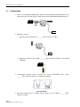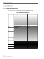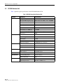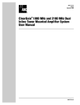
1
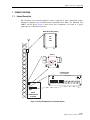
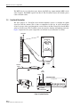
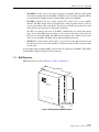
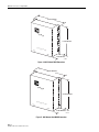
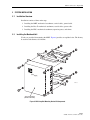
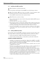
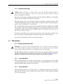
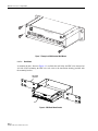
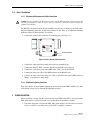
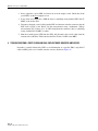
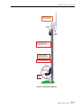
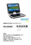
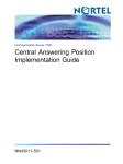
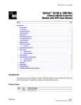
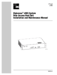
ADCP-75-154
Issue 3
August 2006
ClearGain® Tower Mounted
Amplifier System 900/1800 MHz
User Manual
1379659 Rev A
ADCP-75-154 • Issue 3 • August 2006 • Preface
COPYRIGHT
© 2006, ADC Telecommunications, Inc.
All Rights Reserved
REVISION HISTORY
ISSUE
DATE
REASON FOR CHANGE
1
06/2003
New publication
2
07/2004
Update drawings
3
08/2006
Add 900 MHz Fullband product
LIST OF CHANGES
The technical changes incorporated into this issue are listed below.
PAGE
IDENTIFIER
All
DESCRIPTION OF CHANGE
Update drawings and add 900 MHz specfications.
TRADEMARK INFORMATION
ADC and ClearGain are registered trademarks of ADC Telecommunications, Inc.
DISCLAIMER OF LIABILITY
Contents herein are current as of the date of publication. ADC reserves the right to change the contents without prior notice. In no
event shall ADC be liable for any damages resulting from loss of data, loss of use, or loss of profits and ADC further
disclaims any and all liability for indirect, incidental, special, consequential or other similar damages. This disclaimer of
liability applies to all products, publications and services during and after the warranty period.
This publication may be verified at any time by contacting ADC’s Technical Assistance Center at 1-800-366-3891, extension 73475
(in U.S.A. or Canada) or 952-917-3475 (outside U.S.A. and Canada), or by e-mail to [email protected].
ADC Telecommunications, Inc.
P.O. Box 1101, Minneapolis, Minnesota 55440-1101
In U.S.A. and Canada: 1-800-366-3891
Outside U.S.A. and Canada: (952) 938-8080
Fax: (952) 917-1717
Page ii
ADCP-75-154 • Issue 3 • August 2006 • Preface
TABLE OF CONTENTS
Content
Page
ABOUT THIS MANUAL . . . . . . . . . . . . . . . . . . . . . . . . . . . . . . . . . . . . . . . . . . . . . . . . . . . . . . . . . . . . . . . . . . . . . . . . . v
ADMONISHMENTS . . . . . . . . . . . . . . . . . . . . . . . . . . . . . . . . . . . . . . . . . . . . . . . . . . . . . . . . . . . . . . . . . . . . . . . . . . . v
CERTIFICATION . . . . . . . . . . . . . . . . . . . . . . . . . . . . . . . . . . . . . . . . . . . . . . . . . . . . . . . . . . . . . . . . . . . . . . . . . . . . . v
STANDARDS . . . . . . . . . . . . . . . . . . . . . . . . . . . . . . . . . . . . . . . . . . . . . . . . . . . . . . . . . . . . . . . . . . . . . . . . . . . . . . . v
LIST OF ACRONYMS . . . . . . . . . . . . . . . . . . . . . . . . . . . . . . . . . . . . . . . . . . . . . . . . . . . . . . . . . . . . . . . . . . . . . . . . . . v
1
2
PRODUCT OVERVIEW . . . . . . . . . . . . . . . . . . . . . . . . . . . . . . . . . . . . . . . . . . . . . . . . . . . . . . . . . . . . . . . . . . . . 1
1.1
General Description . . . . . . . . . . . . . . . . . . . . . . . . . . . . . . . . . . . . . . . . . . . . . . . . . . . . . . . . . . . . . . . . 1
1.2
Functional Description . . . . . . . . . . . . . . . . . . . . . . . . . . . . . . . . . . . . . . . . . . . . . . . . . . . . . . . . . . . . . . 2
1.3
MHU Dimensions. . . . . . . . . . . . . . . . . . . . . . . . . . . . . . . . . . . . . . . . . . . . . . . . . . . . . . . . . . . . . . . . . . 3
SYSTEM INSTALLATION . . . . . . . . . . . . . . . . . . . . . . . . . . . . . . . . . . . . . . . . . . . . . . . . . . . . . . . . . . . . . . . . . . . 5
2.1
Installation Overview . . . . . . . . . . . . . . . . . . . . . . . . . . . . . . . . . . . . . . . . . . . . . . . . . . . . . . . . . . . . . . . 5
2.2
Installing the Masthead Unit . . . . . . . . . . . . . . . . . . . . . . . . . . . . . . . . . . . . . . . . . . . . . . . . . . . . . . . . . . 5
2.3
PDU Installation . . . . . . . . . . . . . . . . . . . . . . . . . . . . . . . . . . . . . . . . . . . . . . . . . . . . . . . . . . . . . . . . . . 7
2.4
Bias-T Installation . . . . . . . . . . . . . . . . . . . . . . . . . . . . . . . . . . . . . . . . . . . . . . . . . . . . . . . . . . . . . . . . 11
3
TROUBLESHOOTING . . . . . . . . . . . . . . . . . . . . . . . . . . . . . . . . . . . . . . . . . . . . . . . . . . . . . . . . . . . . . . . . . . . . 11
4
TROUBLESHOOTING 2-PORT CLEARGAIN DUAL DUPLEX TOWER MOUNTED AMPLIFIERS . . . . . . . . . . . . . . . . . . . . . 12
5
6
4.1
Troubleshooting . . . . . . . . . . . . . . . . . . . . . . . . . . . . . . . . . . . . . . . . . . . . . . . . . . . . . . . . . . . . . . . . . 14
4.2
Troubleshooting Hints . . . . . . . . . . . . . . . . . . . . . . . . . . . . . . . . . . . . . . . . . . . . . . . . . . . . . . . . . . . . . 15
MHU SPECIFICATIONS . . . . . . . . . . . . . . . . . . . . . . . . . . . . . . . . . . . . . . . . . . . . . . . . . . . . . . . . . . . . . . . . . . . 16
5.1
DD900 Narrow Band Masthead Unit . . . . . . . . . . . . . . . . . . . . . . . . . . . . . . . . . . . . . . . . . . . . . . . . . . . . 16
5.2
DD900 Full Band Masthead Unit . . . . . . . . . . . . . . . . . . . . . . . . . . . . . . . . . . . . . . . . . . . . . . . . . . . . . . 17
5.3
DD1800 Masthead Unit. . . . . . . . . . . . . . . . . . . . . . . . . . . . . . . . . . . . . . . . . . . . . . . . . . . . . . . . . . . . . 18
CUSTOMER INFORMATION AND ASSISTANCE . . . . . . . . . . . . . . . . . . . . . . . . . . . . . . . . . . . . . . . . . . . . . . . . . . . 19
Page iii
© 2006, ADC Telecommunications, Inc.
ADCP-75-154 • Issue 3 • August 2006 • Preface
Blank
Page iv
© 2006, ADC Telecommunications, Inc.
ADCP-75-154 • Issue 3 • August 2006 • Preface
ABOUT THIS MANUAL
This document describes the ADC ClearGain 900/1800 MHz tower mounted amplifier system and
provides complete instructions for installing this product on a communications tower.
ADMONISHMENTS
Important safety admonishments are used throughout this manual to warn of possible hazards to
persons or equipment. An admonishment identifies a possible hazard and then explains what
may happen if the hazard is not avoided. The admonishments — in the form of Dangers,
Warnings, and Cautions — must be followed at all times. These warnings are flagged by use of
the triangular alert icon (seen below), and are listed in descending order of severity of injury or
damage and likelihood of occurrence.
Danger: Danger is used to indicate the presence of a hazard that will cause severe personal
injury, death, or substantial property damage if the hazard is not avoided.
Warning: Warning is used to indicate the presence of a hazard that can cause severe personal
injury, death, or substantial property damage if the hazard is not avoided.
Caution: Caution is used to indicate the presence of a hazard that will or can cause minor
personal injury or property damage if the hazard is not avoided.
CERTIFICATION
ClearGain 900/1800 MHz has been tested and meets the CE requirements.
STANDARDS
The following listing is a bibliography of applicable regulatory standards:
Safety
EN60950
EMC
EN55022B
Storage
ETS3019-1-1
Transport
ETS3019-1-2
Operation
ETS3019-1-4
LIST OF ACRONYMS
ANT -- Antenna (Port on MHU)
BTS -- Base Transceiver Station
MHU -- Masthead Unit
PDU -- Power Distribution Unit
RF -- Radio Frequency
TMA -- Tower Mounted Amplifier
Page v
© 2006, ADC Telecommunications, Inc.
ADCP-75-154 • Issue 3 • August 2006 • Preface
Blank
Page vi
© 2006, ADC Telecommunications, Inc.
ADCP-75-154 • Issue 3 • August 2006
1
1.1
PRODUCT OVERVIEW
General Description
The ClearGain tower mounted amplifier system is composed of some combination of three
functional components: the ClearGain Power Distribution Unit (PDU), the Masthead Unit
(MHU), and the Bias-T. Figure 1 shows where these components are located in a typical
application on a communications tower.
MASTHEAD UNIT (MHU)
900
OR
1800
BTS
ANT
BIAS-T
BTS
ANT
Bias-T kit
ASSEMBLED IN
KOREA
Date: YYYY/MM/DD
Freq: 800 - 2200MHz
Temp: -40 to +65 C
Input: 5 to 24VDC
Max Current: 2A
P/N: 1344027
S/N: XXXXXXXXX
DC
ClearGain PDU
(SINGLE MODE)
Power Distribution Unit
+ Ð
INPUT
NO COM
NC
ALARM
FAIL
MHU
DISCONNECT
OK
MHU 1
OK
MHU 2
OK
MHU 3
OK
MHU 4
OK
MHU 5
OK
MHU 6
21486-A
BASE
TRANSCEIVER
STATION
Figure 1. Functional Components of a ClearGain System
Page 1
© 2006, ADC Telecommunications, Inc.
ADCP-75-154 • Issue 3 • August 2006
The MHU may be any of the three types shown. One PDU may support multiple MHUs of the
same frequency. Each MHU requires one Bias-T. The ClearGain system also includes power
cables and alarm cables.
1.2
Functional Description
The basic purpose of a ClearGain tower mounted amplifier system is to amplify the uplink
signal just after the antenna. This is done to compensate for the loss in signal strength that
occurs in passage of the signal through the coaxial cable to the Base Transceiver Station (BTS)
at the base of the tower. The ClearGain system also provides alarming and lightning protection.
Figure 2 depicts how the system components are involved in system function. As shown:
ANTENNA
MHU
FILTER/LNA
UPLINK
E
BL
CA A
N
L
IA EN
AX NT
CO O A
T
DOWNLINK
BASE
STATION
BTS
ANT
JUMPER
CABLE
COAXIAL
CABLE
RF SIGNALS
GROUND
DC POWER
FAULT DETECTION
SITE
ALARM
POWER
ClearGain PDU
Power Distribution Unit
BTS
ANT
Bias-T kit
ASSEMBLED IN
KOREA
Date: YYYY/MM/DD
MHU
Freq: 800 - 2200MHz
Temp: -40 to +65 C
Input: 5 to 24VDC
Max Current: 2A
P/N: 1344027
S/N: XXXXXXXXX
DC
+ Ð
INPUT
GROUND
NO COM
NC
FAIL
ALARM
MHU
DISCONNECT
DC POWER
FAULT DETECTION
Figure 2. System Function
Page 2
© 2006, ADC Telecommunications, Inc.
OK
MHU 1
OK
MHU 2
OK
MHU 3
OK
MHU 4
OK
MHU 5
OK
MHU 6
RX/TX (A)
21487-A
ADCP-75-154 • Issue 3 • August 2006
• The MHU—located on top of the tower, performs the amplifier function on the uplink
signal. Two subcomponents of the MHU, an RF filter and a Low Noise Amplifier (LNA),
are involved in the amplifier function. The downlink signal is not amplified.
• The PDU—located in the base station, provides DC current for use in the amplifier
function. The PDU outputs the DC current through a front port from which it travels by
way of a short linkage cable to the Bias-T. The injection of the DC current onto the coaxial
cable will not cause interference with signal transmission.
The PDU also monitors the status of all MHUs simultaneously by sensing their current
draws. If any of the MHUs fails, or if there is a cut or short circuit in the coaxial cable, the
PDU gives an alarm to the BTS. The PDU thus also monitors the condition of the coaxial
cable, not just the MHU. The PDU also has built-in lightning protection.
• The Bias-T—located on the coaxial cable, is a passive device that physically injects the
DC current onto the coaxial cable. The Bias-T injects the current into the center pin of the
coaxial cable.
A single PDU supports multiple MHUs (with one Bias-T required for each MHU). The number
of filters/LNAs supported depends on the system type.
1.3
MHU Dimensions
MHU dimensions are shown in Figure 3, Figure 4, and Figure 5.
250 MILLIMETERS
Clea
rGai
n
280 MILLIMETERS
900
BTS
Dual
Duple
x 2-P
ort T
MA
ANT
63 MILLIMETERS
18790-A
Figure 3. 900 Narrow Band MHU Dimensions
Page 3
© 2006, ADC Telecommunications, Inc.
ADCP-75-154 • Issue 3 • August 2006
248 MILLIMETERS
Clea
rGai
n
332 MILLIMETERS
900
BTS
D ual
Duple
x 2-P
ort T
MA
ANT
83 MILLIMETERS
21488-A
Figure 4. 900 Fullband MHU Dimensions
196 MILLIMETERS
Clea
rGai
n
260 MILLIMETERS
BTS
1800
Dual
Duple
x 2-P
ort T
MA
ANT
63 MILLIMETERS
18791-A
Figure 5. 1800 Narrow Band MHU Dimensions
Page 4
© 2006, ADC Telecommunications, Inc.
ADCP-75-154 • Issue 3 • August 2006
2 SYSTEM INSTALLATION
2.1
Installation Overview
Installation consists of three main steps:
1. Installing the MHU: mechanical attachment, coaxial cables, ground cable.
2. Installing the Bias-T: mechanical attachment, coaxial cables, power cable.
3. Installing the PDU: mechanical attachment, operation power, and alarms.
2.2
Installing the Masthead Unit
U-bolts are provided for mounting the MHU. Figure 6 provides an exploded view. The kit may
be used for tube diameter 30-140 mm.
Clea
rGai
n
16775-C
ANY ClearGain MHU
(DETAILS MAY VARY)
Figure 6. MHU Long Bolt Mounting Bracket Kit Components
Page 5
© 2006, ADC Telecommunications, Inc.
ADCP-75-154 • Issue 3 • August 2006
2.2.1
Installation of the MHU on the Mast
Note: All hardware is specified in metric units.
Before any installation, check that the ClearGain MHU has no visible damages or defects.
Note: The ClearGain MHU must always be installed so that the connectors point
downward. Not more than a 45-degree installation angle is recommended.
1. Place the MHU so that the bracket can be attached to the unit.
Note: The threads are sensitive to damage.
2. Place one half of the bracket (the half with the lifting hook) behind the MHU using two
M8 bolts or long bolts.
3. Fasten the long screws, nuts, washers, and brackets.
4. Before going up to the mast, verify that the remaining washers and nuts are not left on the
ground. Temporarily remove the connector protector plugs, inspect the 7/16 DIN connectors
for damage, and return the connector protector plugs to their respective connectors.
5. Place the ClearGain MHU as close to antenna as possible. Attach the rest of the fasteners
to the bracket system. Fasten the remaining washers and nuts. Verify that the MHU is
tightly in place.
2.2.2
Installing the MHU Ground Cable
Good grounding of the ClearGain MHU is important to protect the unit against voltage surges.
These surges could be caused by, for example, lightning. Install the ground cable as follows:
1. Connect the ground cable to MHU side using M5 attachment screw and washer.
2. Connect the other end of the cable to a good ground (site ground) with a reliable joint.
GROUNDING and BONDING CONSIDERATIONS
• Grounding is very important in tower applications. Shipped with each MHU, is a #6 AWG,
3-foot ground cable with single hole crimp lug connectors on both ends. Installation
hardware is provided to attach one end to the MHU.
• Keep ground wire as short and direct (no loops or knots) as possible, secure it to a good
ground point (metal to metal).
• Following local grounding practices the single hole lug is usually re-terminated by the
tower crew with a double hole lug and bolted to a dedicated tower ground bus.
• In the absence of a dedicated ground, the tower structure itself can be used by using a
exothermic weld joint (not very common) or a mechanical ground clamp. If a clamp is
used, it must be very tight and protected from corrosion effects with a corrosion
preventative compound. It is recommended that the ground integrity/resistance at any
mechanical junction be checked during periods of regular tower maintenance.
• If ground cable length is too short, customer may make a longer ground cable (#6 AWG)
as long as all the mechanical connections are tight and clean.
Page 6
© 2006, ADC Telecommunications, Inc.
ADCP-75-154 • Issue 3 • August 2006
2.2.3
Installing Coaxial Cables
Caution: Before connecting any coaxial cables, ensure that the BTS transmitter output is
turned off and that precautions are taken to ensure that the transmitter cannot be activated
during the equipment installation.
Two short coaxial jumpers should be pre-made. One will connect the BTS port to the hardline
and the other will connect the ANT port to the antenna.
Most installations require two good quality flexible coax jumpers, normally terminated with
7/16DIN-7/16DIN plug connectors. Check gender of hardline and check if Antenna pigtail is
present, adjust accordingly for a correct match.
The coaxial feeder that runs from the base station should be hooked to the BTS port of the MHU
using a jumper cable. The reason for the jumper cable is to ensure that mechanical forces caused
by temperature change will not damage the MHU connectors. Tighten the connectors to 25–30
Nm (18.43–22.13 ft-lbs.) torque.
To improve the reliability of the connection, the connector joint can be protected. This can be
done, for example, by installing specific weatherproof tape over the cable connectors.
Loose cable should be fixed to the tower using cable brackets.
2.3
PDU Installation
2.3.1
Mechanical Attachment of PDU
Warning: Never install the Power Distribution Unit in a wet location or during a lightning
storm. When installing or modifying communication lines, disconnect lines at the interface
before working with uninsulated lines or terminals to prevent electrical shock.
The PDU should be mounted in accordance with local code using appropriate hardware (customer
provided). The PDU has two mounting holes on either side, as shown in Figure 7. Below are
guidelines for standard wall mount, masonry wall mount, and rack mount of the PDU.
2.3.1.1
Standard Wall Mount
When mounting the PDU on a wooden or metal surface, it is recommended that it be installed
on pressure-treated plywood (customer provided) with a minimum thickness of 1.9 cm. The
plywood should be firmly secured to the wall studs.
2.3.1.2
Masonry Wall Mount
When mounting the PDU on a masonry surface, it is important that the bolts (especially the
upper bolts) be located as close as possible to the center of bricks or blocks. Masonry mounting
screws are not provided.
Page 7
© 2006, ADC Telecommunications, Inc.
ADCP-75-154 • Issue 3 • August 2006
Pow
er D
istrib
ution
Unit
+ –
INPU
T
NO
CO M
N
ALAR C FAIL
M
M
DISC HU
ONN
ECT
O
MHU K
1
O
MHU K
2
O
MHU K
3
O
MHU K
4
16772-A
OK
MHU
5
MHU
OK
6
Figure 7. Example of PDU Standard Wall Mount
2.3.1.3
Rack Mount
A mounting bracket, shown in Figure 8, is available that will allow the PDU to be mounted on
a19-inch rack. If mounting the PDU on a rack, refer to the installation drawing provided with
the mounting bracket.
MOUNTING
BRACKET
PDU
18223-A
Figure 8. PDU Rack Mount Bracket
Page 8
© 2006, ADC Telecommunications, Inc.
ADCP-75-154 • Issue 3 • August 2006
2.3.2
Installation of PDU Cables
There are three PDU cables: the ground cable, the alarm cable, and the power cable. Figure 9
shows the cable terminations on the front of the PDU. Connect the cables as follows:
Figure 9. Cable Terminations on Front of PDU
(Left to Right: Power Cable, Alarm Cable, Three MHU Cables, Ground Cable)
1. Connect the ground cable under the grounding screw on the PDU front panel. Connect the
other end of the cable to the site grounding pole.
2. Connect the alarm cable leads to the base station or site alarm system. Use either
“Normally Open” or “Normally Closed” contacts. Figure 10 shows the PDU alarm logic
3. Connect the other end of the alarm cable to the PDU “ALARM” connector.
4. Connect the power cable to the site DC power connector. (The power cable has three leads.
Red is positive, Black is negative, and Yellow/Green is for ground.)
5. Connect the power cable to the “INPUT” connector on the PDU front panel.
Page 9
© 2006, ADC Telecommunications, Inc.
ADCP-75-154 • Issue 3 • August 2006
POWER DISTRIBUTION UNIT
ALARM
RELAY
PDU
ALARM
LOGIC
DC
INPUT
OUTPUTS
16773-A
NO
(NORMALLY
OPEN)
COM
(COMMON)
NC
(NORMALLY
CLOSED)
Figure 10. PDU Alarm Logic
2.3.3
Setting the DIP Switch on the PDU
The PDU has a DIP switch to disconnect unused MHU outputs (see Figure 11). For the MHU
outputs that are used, the DIP switch must be in the “down” position. Unused outputs must be
disconnected by setting the DIP switch to “ON”.
Figure 11. Example of DIP Switch Setting on the PDU
(Switches 1, 2, 3, and 6 Set to “Down” to Indicate Use of MHU Ports 1, 2, 3, and 6)
Page 10
© 2006, ADC Telecommunications, Inc.
ADCP-75-154 • Issue 3 • August 2006
2.4
Bias-T Installation
2.4.1
Mechanical Attachment and Cable Connections
Caution: Prior to installing any Bias-T unit, ensure that the BTS transmitter output is turned off
and that precautions are taken to ensure that the transmitter cannot be activated during the
equipment installation.
The BIAS-T is designed to fasten directly into BTS coax-connector or directly to the feeder cable.
Integrated lightening protection is built into each Bias-T unit. There is no additional mounting
hardware required. Connect the Bias-T as follows:
1. Connect the ground cable to the Bias-T grounding pole (see Figure 12).
BTS
ANT
Bias-T kit
ASSEMBLED IN
KOREA
Date: YYYY/MM/DD
Freq: 800 - 2200MHz
Temp: -40 to +65 C
Input: 5 to 24VDC
Max Current: 2A
P/N: 1344027
S/N: XXXXXXXXX
DC
GROUND TERMINAL
21298-A
Figure 12. Bias-T Ground Cable Connection
2. Connect the other end of the ground cable to the site grounding pole.
3. Connect the BIAS-T “BTS” connector directly into the BTS coax-connector.
4. Connect the coaxial run going to the MHU to the “ANT” port of the BIAS-T.
5. Connect the mini coax cable to the SMB connector of the BIAS-T unit.
6. Connect the other end of the mini coax cable to the PDU front panel SMB connector
TMA1…6 (whichever is being used).
2.4.2
Additional Lightning Protection
If operator chooses to install further lightning protection between the MHU and Bias-T, it must
allow the DC voltage to pass through the lightening protector.
3
TROUBLESHOOTING
When something is wrong with the system, the red alarm LED on the PDU is activated and the
PDU alarm output is activated. In such a case, troubleshoot for problems as follows:
1. Check that the power is fed into the PDU. PDU alarm output is activated if there is no DC
fed in it, or if DC is out of the range (20-50 VDC) or polarity is incorrect.
Page 11
© 2006, ADC Telecommunications, Inc.
ADCP-75-154 • Issue 3 • August 2006
2. Every output has a green LED, and it must be on if the output is used. Check that all the
green LED’s on the used outputs are on.
3. If one of the used outputs has a LED off, there is something wrong with the PDU, Bias-T,
MHU, or the feeder cable.
4. Disconnect the mini coaxial cable from the PDU and measure from the connector, that the
PDU feeds 12VDC to the Bias-T. Do this measurement using a multimeter (Voltage
measurement, DC). If there is 11-13 VDC found from the connector, there is something
wrong with the Bias-T, MHU, or cables.
5. Shut the transmit power OFF from the BTS, and disconnect the coaxial cable from the
Antenna side of the Bias-T. Measure that the Bias-T feeds 12VDC to the MHU.
4
TROUBLESHOOTING 2-PORT CLEARGAIN DUAL DUPLEX TOWER MOUNTED AMPLIFIERS
If trouble is visually indicated by LED’s or no illumination on a specific TMA, swap Bias-T
cables on PDU ports to see if trouble remains or moves. Reference Figure 13.
Page 12
© 2006, ADC Telecommunications, Inc.
ADCP-75-154 • Issue 3 • August 2006
ORIENT THE TMA SO THE
RF CONNECTORS POINT
TOWARDS THE GROUND.
FEEDLINE
JUMPER
HARD
LINE
ANTENNA
JUMPER
COMMON FAILURE POINTS
ARE THE ANTENNA AND FEEDLINE
JUMPERS/CONNECTIONS.
IF A SURGE PROTECTOR IS
ANYWHERE IN BETWEEN
THE BIAS-T AND THE TMA
IT MUST BE ABLE TO PASS DC.
CHECK IF EXTERNAL JUMPERS
OR SURGE PROTECTORS PRESENT.
SHELTER
HARD
LINE
TEST
POINT
Figure 13. Tower Mounted Amplifiers
Page 13
© 2006, ADC Telecommunications, Inc.
ADCP-75-154 • Issue 3 • August 2006
4.1
Troubleshooting
1. Observe and record PDU LED status. Disable or disconnect RF from BTS. Remove any
surge protectors. Disconnect Bias-T from the antenna feedline/hardline/jumper/protector.
HARD
LINE
SURGE
PROTECTOR
PDU
2. Multimeter checks:
a. Measure voltage on the Bias-T _______ VDC. Normal is 13VDC.
PDU
b. Measure resistance of the feedline _______ Ohms. Normal is High or Very high Ω
(KΩ/ΜΩ).
HARD
LINE
3. Antenna/cable analyzer checks. Measure the in-band RL/VSWR of the system
_______dB or ratio. Check distance to Fault for anomalies.
0
17
dB
Typical RL Sweep
4. Re-connect Bias-T with a T adapter. Verify voltage on the T adapter _______VDC.
Normal is 13VDC.
Page 14
© 2006, ADC Telecommunications, Inc.
ADCP-75-154 • Issue 3 • August 2006
HARD
LINE
PDU
PDU DC supply (18-56 VDC with 5A fuse/breaker).
5. Re-connect to original configuration and return to service. PDU should illuminate a green
LED for each active TMA if there are no faults in the system.
6. Check with operators for improved performance.
4.2
Troubleshooting Hints
•
•
•
•
If voltage is outside of the normal range, trace it back towards the fault.
If no resistance or low resistance, check protector, feedline, jumpers and TMA.
If high resistance, check to see if TMA is installed or for a discontinuity up to the TMA.
Normal in-band RL should be greater than 14dB. If less than 14dB, check protector,
feedline, jumpers and antenna.
• Mark receive and transmit bands to verify correct filtering.
• Check distance to fault to identify any anomalies on the feedline.
Page 15
© 2006, ADC Telecommunications, Inc.
ADCP-75-154 • Issue 3 • August 2006
5
5.1
MHU SPECIFICATIONS
DD900 Narrow Band Masthead Unit
Table 1 provides typical specifications for the DD900 Full Band Masthead Unit.
Table 1. DD900 Narrow Band Masthead Unit
CATEGORY
ELECTRICAL
FILTER
POWER HANDLING
POWER
PHYSICAL
ENVIRONMENTAL
QUALITY
Page 16
© 2006, ADC Telecommunications, Inc.
PARAMETER
SPECIFICATION
Nominal impedance of RF input and outputs
Frequency Range
TX
RX
Duplex Filter Bandwidth
Passband (RX)
Gain
Noise Figure
Dynamic Range
Input at 1 dB compression
IIP3
Insertion Loss of TX Path (TX to Antenna)
Passband Return Loss
TX Band
RX Band
Intermodulation
Maximum Input Power at Each BTS Input
RMS Power TX
Peak Power TX
Duration
Period Between Peaks
Fault Management
Operational Voltage
Operational Current
Alarm Current Level
50 Ohm
Dimensions (HxWxD)
Weight
Color
Housing
Operating Temperature
Outdoor Protection
MTBF
Lightening Protection
935–960 MHz or 925–950 MHz
890–915 Mhz or 880–905 Mhz
25 MHz
12 dB
1.4 dB typical
3.0 dB
+15 dBm
0.2 dB
20 dB
20 dB
–120 dBm
200 W
1.44 kW
20 microseconds
550 microseconds
Bypass
7 to 15 VDC
150 mA
175 ± 5 mA
280 x 250 x 85 mm
5.5 kg
Silver
Aluminum
–40° C to +65° C
IP65
< 500,000 hours
IEC 801-5 and IEC 1312
ADCP-75-154 • Issue 3 • August 2006
5.2
DD900 Full Band Masthead Unit
Table 2 provides typical specifications for the DD900 Masthead Unit.
Table 2. DD900 Full Band Masthead Unit
CATEGORY
PARAMETER
SPECIFICATION
ELECTRICAL
Nominal impedance of RF input and outputs
50 Ohm
Frequency Range
TX
925–960 MHz
RX
880–915 Mhz
Duplex Filter Bandwidth
35 MHz
Passband (RX)
Gain
12 dB
Noise Figure
1.4 dB typical
Dynamic Range
Input at 1 dB compression
IIP3
Insertion Loss of TX Path (TX to Antenna)
FILTER
POWER
PHYSICAL
ENVIRONMENTAL
QUALITY
+3.0 dB
+15 dBm
0.2 dB
Passband Return Loss
TX Band
18 dB
RX Band
18 dB
Intermodulation
–115dBm
Operational Voltage
7 to 15 VDC
Operational Current
140 mA ± 10 mA
Alarm Current Level
350 ± 10 mA
Dimensions (HxWxD)
332 x 250 x 83 mm
Weight
6.6 kg
Color
Silver
Housing
Aluminum
Operating Temperature
–40° C to +65° C
Outdoor Protection
IP65
MTBF
< 500,000 hours
Lightening Protection
IEC 801-5 and IEC 1312
Page 17
© 2006, ADC Telecommunications, Inc.
ADCP-75-154 • Issue 3 • August 2006
5.3
DD1800 Masthead Unit
Table 3 provides typical specifications for the DD1800 Masthead Unit.
Table 3. DD1800 Narrow Band Masthead Unit
CATEGORY
PARAMETER
SPECIFICATION
FILTERS
RX (up link) frequency range
1710–1755, 1720–1765, or 1740–1785 MHz
TX (down link) frequency range
1805–1850, 1815–1860, or 1835–1880 MHz
Insertion Losses
1800 Tx
0.2 dB
UMTS Rx and Tx
0.2 dB
900 Rx and Tx
0.1 dB
Intermodulation at RX Band
–120 dBm
Power Handling Capability
500W RMS, 10 kW peak
Return Loss
20dB
Gain
12 dB fixed
Passband ripple
± 0.5 dB
Noise Figure
1.5 dB
IIP3
+ 13 dBm
Bypass Loss Typical
< 2.0dB, RF relay connection
Dimensions (HxWxD)
196 x 260 x 63 mm
Weight
5 kg
Color
Silver
Antenna Connector
7/16 DIN receptor
BTS Connector
7/16 DIN receptor
INTERMODULATION
Intermodulation
–120 dBm
ENVIRONMENTAL
Operating Temperature
–40° C to +65° C
Outdoor Protection
IP65
MTBF
< 500,000 hours
Lightening Protection
IEC 801-5 and IEC 1312
LNA WITH (FILTER)
PHYSICAL
CONNECTORS
QUALITY
Page 18
© 2006, ADC Telecommunications, Inc.
ADCP-75-154 • Issue 3 • August 2006
6
CUSTOMER INFORMATION AND ASSISTANCE
PHONE:
U.S.A. OR CANADA
Sales: 1-800-366-3891 Extension 73000
Technical Assistance: 1-800-366-3891
Connectivity Extension 73475
Wireless Extension 73476
EUROPE
Sales Administration: +32-2-712-65 00
Technical Assistance: +32-2-712-65 42
EUROPEAN TOLL FREE NUMBERS
Germany: 0180 2232923
UK:
0800 960236
Spain:
900 983291
France: 0800 914032
Italy:
0800 782374
ASIA/PACIFIC
Sales Administration: +65-6294-9948
Technical Assistance: +65-6393-0739
ELSEWHERE
Sales Administration: +1-952-938-8080
Technical Assistance: +1-952-917-3475
WRITE:
ADC TELECOMMUNICATIONS, INC
PO BOX 1101,
MINNEAPOLIS, MN 55440-1101, USA
ADC TELECOMMUNICATIONS (S'PORE) PTE. LTD.
100 BEACH ROAD, #18-01, SHAW TOWERS.
SINGAPORE 189702.
ADC EUROPEAN CUSTOMER SERVICE, INC
BELGICASTRAAT 2,
1930 ZAVENTEM, BELGIUM
PRODUCT INFORMATION AND TECHNICAL ASSISTANCE:
[email protected]
[email protected]
[email protected]
13944-M
[email protected]
Contents herein are current as of the date of publication. ADC reserves the right to change the contents without prior notice.
In no event shall ADC be liable for any damages resulting from loss of data, loss of use, or loss of profits and ADC further
disclaims any and all liability for indirect, incidental, special, consequential or other similar damages. This disclaimer of
liability applies to all products, publications and services during and after the warranty period. This publication may be
verified at any time by contacting ADC's Technical Assistance Center.
© 2006, ADC Telecommunications, Inc.
All Rights Reserved
Page 19