1
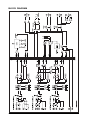
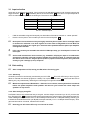
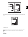
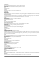
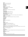
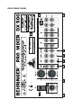
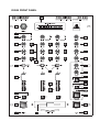
DX500
PRO MIXER
User´s Manual
Version 1.2
July 2000
www.behringer.com
E
EG-Declaration of Conformity
INTERNATIONAL GmbH
acc. to the Directives
89/336/EWG and 73/23/EWG
We,
BEHRINGER INTERNATIONAL GmbH
Hanns-Martin-Schleyer-Straße 36-38
D - 47877 Willich
Name and address of the manufacturer or the introducer of the product on the market who is established in the EC
herewith take the sole responsibility to confirm that the product:
PRO MIXER DX500
Type designation and, if applicable, Article-No
which refers to this declaration, is in accordance with the following standards or
standardized documents:
x EN 60065
x EN 55020
x EN 55013
x EN 61000-3-2
x EN 61000-3-3
x EN 55022
The following operation conditions and installation arrangements have to be presumed:
acc. to Operating Manual
B. Nier, President
Name, address, date and legally binding signature of the person responsible
2
Willich, 01.07.1998
SAFETY INSTRUCTIONS
CAUTION:
To reduce the risk of electrical shock, do not remove
the cover (or back). No user serviceable parts inside;
refer servicing to qualified personnel.
WARNING: To reduce the risk of fire or electrical shock, do not
expose this appliance to rain or moisture.
This symbol, wherever it appears, alerts
you to the presence of uninsulated
dangerous voltage inside the enclosure
- voltage that may be sufficient to constitute a risk of shock.
This symbol, wherever it appears, alerts
you to important operating and maintenance instructions in the accompanying
literature. Read the manual.
DETAILED SAFETY INSTRUCTIONS:
All the safety and operation instructions should be read before the appliance is operated.
Retain Instructions:
The safety and operating instructions should be retained for future reference.
Heed Warnings:
All warnings on the appliance and in the operating instructions should be adhered to.
Follow instructions:
All operation and user instructions should be followed.
Water and Moisture:
The appliance should not be used near water (e.g. near a bathtub, washbowl, kitchen sink, laundry tub, in a wet
basement, or near a swimming pool etc.).
Ventilation:
The appliance should be situated so that its location or position does not interfere with its proper ventilaton. For
example, the appliance should not be situated on a bed, sofa rug, or similar surface that may block the
ventilation openings: or placed in a built-in installation, such as a bookcase or cabinet that may impede the
flow of air through the ventilation openings.
Heat:
The appliance should be situated away from heat sources such as radiators, heat registers, stoves, or other
appliance (including amplifiers) that produce heat.
Power Source:
The appliance should be connected to a power supply only of the type described in the operating instructions
or as marked on the appliance.
Grounding or Polarization:
Precautions should be taken so that the grounding or polarization means of an appliance is not defeated.
Power-Cord Protection:
Power supply cords should be routed so that they are not likely to be walked on or pinched by items placed
upon or against them, paying particular attention to cords and plugs, convenience receptacles and the point
where they exit from the appliance.
Cleaning:
The appliance should be cleaned only as recommended by the manufacturer.
Non-use Periods:
The power cord of the appliance should be unplugged from the outlet when left unused for a long period of time.
Object and Liquid Entry:
Care should be taken so that objects do not fall and liquids are not spilled into the enclosure through openings.
Damage Requiring Service:
The appliance should be serviced by qualified service personnel when:
- The power supply cord or the plug has been damaged; or
- Objects have fallen, or liquid has been spilled into the appliance; or
- The appliance has been exposed to rain; or
- The appliance does not appear to operate normally or exhibits a marked change in performance; or
- The appliance has been dropped, or the enclosure damaged.
Servicing:
The user should not attempt to service the appliance beyond that is described in the Operating Instructions. All
other servicing should be referred to qualifield service personnel.
3
E
BLOCK DIAGRAM
4
DX500
Professional DJ mixer with a total of 6 stereo sources on 3 dual-input channels
PRO MIXER
E
s Internal 12 second digital sampler with loop function offers you new creative possibilities
s High class microphone input with peak indicator
s High precision phono pre-amps for bass power and crystal clean sound
s Ultra-musical 3-band EQ with Kill switches for each band gives you all the creative power
s Ultra-low noise design comparable to studio grade consoles
s Replaceable and ultra-high quality crossfader guarantees 100.000 lifecycles
s Large Punch buttons at the crossfader – your big plus for creative mixing!
s PFL switches with status LEDs on all channels
s A Balance control allows you to blend between Main and PFL on the phones section
s External effect facility with send and return
s Additional, adjustable Zone output allows you to control the level of a monitor or secondary area
s Main outputs on professional balanced gold-plated XLR and on RCA connectors for parallel recording
s High precision 12-digit LED VU meters
s High-quality 60 mm channel faders as found in professional recording consoles
s Rugged external power supply ensures maximum signal integrity
s Top quality components ensure superb audio performance and maximum endurance
s Super-rugged construction ensures long life, even under the most demanding conditions
s Manufactured under ISO9000 certified management system
5
FOREWORD
Dear Customer,
Welcome to the team of PRO MIXER users and thank you very much for expressing your confidence in
BEHRINGER products by purchasing this unit.
It is one of my most pleasant tasks to write this letter to you, because it is the culmination of many months of
hard work delivered by our engineering team to reach a very ambitious goal: presenting an outstanding mixer
for flexible use in studios, clubs or at home. The task to develop our new PRO MIXER series certainly meant
a great deal of responsibility, which we assumed by focusing on you, the discerning user and musician. It also
meant a lot of work and night shifts to accomplish this goal. But it was fun, too. Developing a product usually
brings a lot of people together, and what a great feeling it is when everybody who participated in such a project
can be proud of what we’ve achieved.
It is our philosophy to share our joy with you, because you are the most important member of the BEHRINGER
family. With your highly competent suggestions for new products you’ve greatly contributed to shaping our
company and making it successful. In return, we guarantee you uncompromising quality (manufactured under
ISO9000 certified management system) as well as excellent technical and audio properties at an extremely
favorable price. All of this will enable you to fully unfold your creativity without being hampered by budget
constraints.
We are often asked how we can make it to produce such high-grade devices at such unbelievably low prices.
The answer is quite simple: it’s you, our customers! Many satisfied customers means large sales volumes
enabling us to get better conditions of purchase for components, etc. Isn’t it only fair to pass this benefit back
to you? Because we know that your success is our success, too!
I would like to thank all people whose help on “Project DX500“ has made it all possible. Everybody has made
very personal contributions, starting from the designers of the unit via the many staff members in our company
to you, the user of BEHRINGER products.
My friends, it’s been worth the trouble!
Thank you very much,
Uli Behringer
6
TABLE OF CONTENT
1. THE MANUAL .......................................................................................................................... 8
2. PRO MIXER OVERVIEW .........................................................................................................8
2.1
2.2
2.3
2.4
2.5
Highly accurate MAIN and PFL VU bargraph meters ......................................................................
How will YOU use YOUR DX500? ...................................................................................................
PSU (Power Supply Unit) ................................................................................................................
Warranty ........................................................................................................................................
Packing ..........................................................................................................................................
8
9
9
9
9
3. INPUT CHANNELS .................................................................................................................. 9
3.1 Input selection .............................................................................................................................. 10
3.2 Gain setting ................................................................................................................................... 10
3.2.1 Quick way ........................................................................................................................... 10
3.2.2 Gain setting by using PFL ................................................................................................... 10
3.3 Equalizer ....................................................................................................................................... 11
4. MASTER SECTION ............................................................................................................... 11
4.1
4.2
4.3
4.4
4.5
Output ............................................................................................................................................ 11
Cross fader .................................................................................................................................... 11
Transforming with Punch ............................................................................................................... 11
Effects loop ................................................................................................................................... 12
Outputs ......................................................................................................................................... 12
5. PFL AND HEADPHONES ...................................................................................................... 12
5.1 PFL : Pre-Fader Listen ................................................................................................................. 12
5.2 Headphones - read carefully! ........................................................................................................ 13
6. SAMPLER .............................................................................................................................. 13
6.1 Record mode ................................................................................................................................ 13
6.2 Playback mode ............................................................................................................................. 13
7. CONNECTIONS ..................................................................................................................... 14
7.1 PRO MIXER DX500 connections .................................................................................................. 14
7.2 Plug soldering guide ..................................................................................................................... 14
8. GLOSSARY ........................................................................................................................... 15
9. SPECIFICATIONS .................................................................................................................. 19
10.WARRANTY .......................................................................................................................... 20
7
E
1. THE MANUAL
We know that reading manuals can be a bore, and that you are probably impatient to get started with your new
DX500 mixer, if you haven’t already! It is true that with a modicum of knowledge about audio equipment you
could get up and running successfully, but chances are you will not be able to exploit the full potential of your
DX500 (or yourself) until you have some of its more advanced features explained. Please, please at least read
through all the text in this section, which contains important safety tips to help preserve you and your valuable
equipment.
+
You’ll get nowhere with your DX500 unless it is properly connected to your music sources,
power amplifiers, tape recorder etc. We strongly advise that you never use cheap connecting
plugs for audio - use only gold-plated ones, as these are best at resisting corrosion. Run any
mic on a balanced line to minimise unwanted interference, and check those mains plugs for
loose cable clamps or electrical contacts frequently!
Good quality plugs are extremely important, all the more so where connections are left untouched for long
periods. (Unplugging leads frequently can help to keep contacts clean by mechanical abrasion). Also moisture
in a humid nightclub greatly accelerates the buildup of oxide (e.g. rust) on metal contacts.
+
+
Never patch line level devices into your highly sensitive phono inputs. Phono cartridge output
is measured in millivolts. CD and tape players are of the order of magnitude of a volt. With line
levels you are looking at signals 100 times more powerful than a phono pre-amplifier is designed to handle !
Please always ensure that the mixer power supply is securely connected to the mixer before
you turn on the mains supply. Power amplifiers should always be turned on last of all in order
to minimize switch-on thumps, which can easily damage loudspeakers. Check that there is no
signal going through the DX500 when the amps are switched on in order to avoid any sudden
volume surges. Best turn down all output faders and rotary controls first !
This manual is a combination of figures and text. Together these precisely define and describe all the functions
of your DX500. For reasons of clarity you might find certain text or subject matter appears more than once in
the manual. This means we pay a little more in printing and publishing costs, but it does mean that each
section is self-contained and therefore easier for you to read.
Sometimes technical information is provided in brackets. Don’t worry - you don’t need to know what the figures
mean in order to have success with your DX500. This info is included for the benefit of sound engineers, not
DJ’s! The manual is also crammed full of creative ideas on how to play your DX500 to full advantage. Try to read
it from cover to cover at least once. Otherwise you’ll never know what possibilities you might be missing out on!
2. PRO MIXER OVERVIEW
The DX500 is a multi-functional stereo mixer designed for all applications where pre-recorded music is mixed
and played. It is equally at home, in dance clubs, personal DJ setups and broadcast studios. It has three
stereo music channels. The first of these can accept a DJ mic. The mic channel is routed to the main mix
directly. Music channels 2 and 3 pass through a super-smooth cross fader.
2.1 Highly accurate MAIN and PFL VU bargraph meters
The main output level is constantly monitored by a pair of highly accurate VU bargraph meters
. In addition,
all channels have PFL (Pre-Fader-Listen). This means that you can see (on the bargraph meters) and hear (on
headphones)
the music you are about to play - essential if you want to come in at the same level as and
in time with the music currently playing. All professional DJ’s strive to do this, often overlapping two tracks, or
slowly cross fading between them. (These and other DJ mixing tricks will be explained elsewhere in this
manual.)
8
1. THE MANUAL
2.2 How will YOU use YOUR DX500?
Your DX500 is a creative instrument. Learn to play it well. If possible, experiment with it “off-line” – before you
use it in earnest in a club or studio. It offers you many creative music mixing possibilities, with its ultra
DJ-friendly control surface. In addition many special features have been included to enhance the flexibility,
creativity and ease of operation of your mix. For example, the on-board CD quality digital sampler lets you
capture and edit a sound with instant replay available at the touch of a button. Loop a breakbeat, stutter a vocal
hook, trigger an ambient effect. Also you might notice that kill switches are included on every channel, making
professional sounding dub EQ effects child’s play. But first connect the external power supply unit to the PSU
input
of your DX500, plug it in and switch it on
(always use this sequence).
. In addition all
We have given particular attention to metering your music with PFL offered on every channel
channels have clip LEDs
constantly looking for input overload distortion. You will also see that many of
the switches on your DX500 have an associated status LED, to let you know when it is engaged. Just another
way in which we try to make life easier for you, the DJ.
2.3 PSU (Power Supply Unit)
Any amplifier circuit is limited in its transient response by the available current. Every mixer has numerous
line level operational amplifiers (op-amps) inside. When being driven hard, many desks begin to show signs
of stress due to power supply limitations. Not so with the PRO MIXER DX500. The sound will always stay
clean and crisp right up to the operating limits of the op-amps themselves, thanks to our generous 30 W
external power supply unit.
Please connect the PSU with the PRO MIXER DX500 PSU connector
and turn it on with the POWER ON switch
.
+
on the rear panel of your mixer
Do not connect the PSU to the PRO MIXER while the PSU is connected to the mains supply.
Connect switched-off desk and PSU first before you connect the PSU to the mains supply.
2.4 Warranty
Please take time to have the warranty card filled out completely by your specialized dealer and return it within
14 days after the date of purchase, so as to be entitled to benefit from our extended warranty. You will find the
serial number
of your DX500 on the rear panel.
2.5 Packing
Your BEHRINGER PRO MIXER DX500 was carefully packed in the factory and the packaging was designed to
protect the unit from rough handling. Nevertheless, we recommend that you carefully examine the packaging
and its contents for any signs of physical damage, which may have occurred in transit.
+
If the unit is damaged, please do not return it to us, but notify your dealer and the shipping
company immediately, otherwise claims for damage or replacement may not be granted.
Shipping claims must be made by the consignee.
3. INPUT CHANNELS
Plug a phono (turntable) or line source (CD player etc.) into an appropriate input
. Plug a dynamic
microphone into the DJ mic input
on the front panel (if required). Play music or speech at a typical
volume to check out and set up the channel.
,
The mic pre-amp is of the same quality as those found in our award-winning EURODESK
studio consoles. This gives an incredibly warm, clear and noiseless performance. Mic inputs
are on balanced XLR and 1/4" jacks respectively. Balanced operation gives best noise
performance. Unbalanced microphones need to have XLR pins 1 and 3 shorted.
3. INPUT CHANNELS
9
E
3.1 Input selection
Inputs are on the DX500’s back panel. Your input source is selectable between a pair of stereo inputs by the
toggle switches
and
immediately above the channel fader
. The choice of inputs depends on
which of channels 1 through 3 you are looking at. The mixer is set up as follows:
Channel
Input 1
Input 2
1
MIC*
PHONO/LINE**
2
PHONO 2
LINE 2
3
PHONO 3
LINE 3
Tab. 3.1: Channel inputs
*
If MIC is selected the signal is fed equally into both sides of the stereo channel i.e. “center-panned”.
**
Here the choice phono / line is made by a switch on the back panel
+
,
J
.
Never patch line level devices into your highly sensitive phono inputs. Phono cartridge output
is measured in millivolts. Line level signals are of the order of magnitude of a volt. With line
levels you are looking at a signal up to 100 times more powerful than the phono pre-amplifier
is designed to handle!
If for some reason your turntable has a built-in RIAA pre-amp, you should patch it into a line
level input.
A mix could include three music sources (e.g. turntables, CD players, tapes or a combination
spread over channels 1 through 3) and the sampler for creative DJ work, or a mono DJ mic and
two stereo music sources. Only the phono (and mic) inputs are device-specific, being matched
exactly to your cartridge (or mic) response.
3.2 Gain setting
+
Gain is dependent on EQ. Set up your EQ before fine-tuning gain.
3.2.1 Quick way
Channel input level is continuously monitored by an CLIP-LED
. This CLIP LED lets you know if you’re
about to overload the channel (it lights at +18 dB). Turn up the channel GAIN
control until this LED is
flashing only very intermittently. Back off gain until the light no longer illuminates.
+
Watch the output meters! Remember – distortion is not volume, and any distortion introduced
before the power amplifiers and speakers will worsen your sound and cause amps and
speakers to clip sooner.
3.2.2 Gain setting by using PFL
Pre-Fader-Listen is the professional way to set gain, and we always recommend you do it if you have the
time. Engaging PFL
temporarily sends the channel signal to the output meters. Adjust GAIN until the PFL
meter is hitting the range between 0 and +7 dB. Probably it’s best to aim for +4 dB peak readings, allowing you
to whack the channel faders full on (+6 dB) without output overload (+4 +6 = +10 dB per channel output). Once
gain has been set for a channel, release its PFL button.
+
10
Normally you will want to PFL only one channel at a time.
3. INPUT CHANNELS
3.3 Equalizer
Channel EQ comprises three control knobs and three switches. The tone controls enable cut and boost of
TREBLE
, MID
; and BASS
frequencies respectively (see below for specs.) EQ can sweeten or
effect a track, with the fading out and in of frequency bands being very popular.
EQ
Frequency
Range
Centre
Treble
Shelving EQ
10 kHz
+/- 15 dB
OFF
Mid
Peaking EQ
1600 Hz
+/- 10 dB
OFF
Bass
Shelving EQ
50 Hz
+/- 10 dB
OFF
E
Tab. 3.2: EQ frequency bands
When the KILL switches
are depressed the corresponding tone control is defeated and that band is
attenuated. It is as if the tone control is turned fully counter-clockwise. This is particular useful if you want to
bring in a new piece of music one band at the time. It is also possible for instance to mix the mid frequency
band of one track with the high and low of another. You can then reverse that very quickly.
4. MASTER SECTION
4.1 Output
Channel output level is controlled by a precision stereo 60 mm fader
,
.
The faders used are true-log faders. These give ultra-smooth operation even at low levels, on
a par with those used in the most expensive studio consoles.
Channel 1 goes directly into the mix. Channels 2 and 3 go to opposing ends of the cross fader.
4.2 Cross fader
Channels 2 and 3 are selected/blended by using a cross fader, modestly legended ULTRA-HIGH QUALITY
FADER
. When set fully to the left, only Channel 2 is heard in the mix, and vice versa. We know how much
you rely on the cross fader for mixing. For this reason we have ensured that it is incredibly durable and
smooth-acting.
,
The cross fader is an ultra-high quality fader. Its monorail design means that you can expect a
massive 100,000 smooth operations before wear & tear even becomes a factor.
4.3 Transforming with Punch
Transfroming is a DJ term used to describe the inserting of a piece of music rhythmically into another piece.
When the cross fader is to one side of the middle pushing the punch button on the opposite side will bring up
the level of that side of the cross fader. This way it is possible to punch in a piece of music, typically a certain
drum track or lyric, into the playing piece of music. Traditionally this is done by rapidly pushing the fader up
from minus infinity to 0 or +6 dB or moving a cross fader from one side to the middle to give a stuttering or
“gated” effect. These methods are still valid, but if you are looking for instantaneous transforming check out our
ergonomic alternative – a pair of big PUNCH buttons, operating on channels 2
and 3
. We are sure
you will grow to love their speed and ease of operation.
+
This is the first time we have come across any really BIG buttons on the DX500. At this point it’s
worth pointing out that all the smaller switches on your DX500 are latching. This means they stay
down until you hit them again. Big buttons are all non-latching, or momentary in operation. This
means that they are only active when your finger (or other appendage) is actually holding them
down, like the keys on a MIDI keyboard. These are ideal for executing transformations or sampletriggering, as you will very quickly find as you get into using your DX500.
4. MASTER SECTION
11
J
Try running a rhythm track through channel 2 (cross fader fully to the left). Now use the
PUNCH 3 button to manually chop in a sustained signal like orchestral music, ambient sounds,
noise, whatever.
4.4 Effects loop
Between faders 2 and 3 lies the EFFECT button
. Depressing the EFFECT button will interrupt the signal
flow between the main mix and MAIN OUT / ZONE OUT. You can send the output of the DX500 to an external
signal processing device by using the EFFECT IN/OUT SEND
and return the processed signal via the
EFFECT IN/OUT RETURN
. Use this feature to connect an equalizer, limiter, denoiser or even an echo or
delay. When the effect button is depressed the corresponding LED lights up.
+
,
To prevent accidental cancellation of the output signal it is recommended to connect the effect
output directly to the effect input with a stereo cinch cable or with two bridges in case you do
not insert any effects devices.
At the effect send the master signal is always present. If you are not using the send for an
effect you can use it either as a record out or as a feed for a light controller. Because the send
is pre-fader the recording is unaffected by the setting of the main volume or zone volume.
4.5 Outputs
Stereo outputs include MAIN
and
and ZONE
(Max. output +28 dBu balanced, +22 dBu unbalanced). Both are on cinch pairs, with MAIN additionally being available on professional balanced XLR-type
connectors. Level to these outputs is controlled by a pair of rotary controls marked MAIN OUT
and
ZONE OUT
, top right on the top panel. The MAIN OUT level is always displayed on the precision VU
bargraph meters unless PFL is deployed.
+
Watch the output meters! Remember – distortion is not volume, and any distortion introduced
before the power amplifiers and speakers will worsen your sound and cause amps and speakers to clip sooner.
MAIN would normally feed the main P.A. system (or Hi-Fi amp if you are mixing at home). The ZONE stereo
output is designed to be used for feeding the mix into a separate sound system such as DJ foldback, or a
different room or area in a dance club.
5. PFL AND HEADPHONES
5.1 PFL: Pre-Fader Listen
When any PFL button
is depressed the main meters
will change to displaying PFL level. PFL is the
way to hear, cue and set up a piece of music before you play it out in the mix.
J
In the club environment, things get messy. You can’t hear any sound in isolation, either on a
foldback system or headphones, because both are to some extent drowned out by the main
P.A. system. You should, however, be able to hear the PFL signal loud enough to detect the
beat, cue starts etc. What you can’t do is to judge by ear exactly what level the next track will
come in at. For that you must use your eyes, and the highly-accurate bargraph VU meters.
PFL is also used to accurately set input GAIN. With a channel’s PFL button engaged (DOWN) you can
accurately set the input GAIN by making a typical noise and observing the main meters.
+
12
If you are in the habit of slamming the channel faders all the way up (+6 dB), try to keep your
MAIN OUT control
at a compensatory lower level to make sure you don’t risk distortion. To
do this successively engage and disengage PFL on the channel currently playing. Adjust MAIN
OUT until the PFL and MAIN meter readings are identical. With channel faders at +6 dB and
main output level at -6 dB your DX500 has unity gain from input (post gain) to output. Now
PFL and MAIN metering should show the same level, allowing direct visual comparison between outgoing (playing) and incoming (cue) tracks.
5. PFL AND HEADPHONES
5.2 Headphones – read carefully!
The PHONES section lies to the far right hand side of the DX500, below the MAIN and ZONE OUT controls.
PHONES
controls headphones output level and the PHONES jack
is placed at the front of the DX500.
Right, that’s the easy bit explained. Now pay attention. BALANCE
controls the blend of the PFL and MAIN
mix signals. This gives you the interesting possibility of hearing both the outgoing (MAIN, pre MAIN OUT
control) and incoming (PFL) tracks simultaneously through a single output, via your headphones.
E
6. SAMPLER
A sampler is a digital device for recording and playing back audio. Your DX500 sampler enables you to
capture and replay a fragment of audio. This can be anything: a drum pattern or a vocal hook. Up to 24
seconds of audio can be recorded, repeated and re-tuned.
6.1 Record mode
The sampler section is sited bottom right on your DX500. Two (twin-LED illuminated) mode buttons determine
the sampler’s status. With PLAY/RECORD
you select between playback and record. The selected mode
is indicated by the illumination of one of the two status LEDs
. In RECORD mode the sampler is always
listening to the PFL bus. Any channel with PFL depressed is (in addition to being sent to the bargraph meters
and headphones output) sent to the input of the sampler. In RECORD mode the sampler is primed to begin
recording once the big START/STOP key
has been hit. The sampler stops recording when the START/
STOP key is hit again. For the duration of the START/STOP keypress, the sampler has been recording, with
a maximum of 24 seconds at 50% or 12 seconds at 100% speed. The ACTIVE LED
lets you know if
anything is routed to the sampler input (i.e. whether any PFL button is down).
+
During recording sampler input level is displayed on the bargraph meters
(remember your meters are looking at PFL). The sampler will overload at +7 dB. The onset of digital
distortion, unlike analog, is sudden and horrid. Avoid and always monitor the PFL meter.
6.2 Playback mode
Once you have captured a piece of audio, you can play it back by first switching to PLAY mode
then
pressing the START/STOP key
. Playback mode can be selected by the self-explanatory twin-LED
illuminated SINGLE/REPEAT switch
. In single mode the sample is played only once. Pressing the START/
STOP key while the sample is playing will start the sample again. This enables you to create a stuttering
effect. In repeat mode pressing the START/STOP key while playing will stop the circle. Playback may be
varispeeded from 50% to 100% by the SPEED control
, while playback level can be adjusted by the
SAMPLER OUT control
.
+
,
,
Sampler operations do not affect the mix from the three desk channels.
With the speed control it is also possible to record slower or faster to create some real radical
effects.
When recording drums, start and stop on the first beat of a bar. Now when you playback in
REPEAT mode you should generate a seamless rhythm track.
6. SAMPLER
13
7. CONNECTIONS
7.1 PRO MIXER DX500 connections
Follow us on a walk along the connection on the rear panel of your PRO MIXER, starting left:
Main outputs. Balanced XLR, wired pin 1 = ground/screen, pin 2 = hot (+ve) and pin 3 = cold (-ve).
Main outputs. RCA sockets, unbalanced.
Zone outputs. RCA sockets, unbalanced.
Phono/line inputs. Unbalanced RCA sockets, to connect all input devices.e = ground/screen.
Effect send. Master signal always present on this RCA connector.
Effect return. RCA sockets to return the processed signal, this signal is sent directly to the MAIN OUT
and ZONE OUT controls.
And on the front panel:
Mic input. Balanced XLR, wired pin 1 = ground/screen, pin 2 = hot (+ve) and pin 3 = cold (-ve).
Mic input. 1/4" jack socket, tip = hot (+ve), ring = cold (-ve) and sleeve = ground/screen.
Phones. 1/4" jack socket, tip = left signal, ring = right signal and sleeve = ground/screen.
+
Please ensure that only qualified persons install and operate the PRO MIXER DX500. During
installation and operation the user must have sufficient electrical contact to earth. Electrostatic charges might affect the operation of the PRO MIXER DX500!
7.2 Plug soldering guide
You will need a lot of cables for different purposes – see the following figures to make sure you have got the
right ones.
Use custom-made RCA cables for all connections which use RCA sockets (centre post = signal (+ve) and
sleeve = ground/screen). If your power amplifier is equipped with professional XLR inputs use the balanced XLR
outputs of the DX500 for optimal performance. Buy them either custom built of wire them as follows:
Fig. 7.1: Balanced XLR connectors
The Microphone jack input can be used either balanced or unbalanced as shown.
14
7. CONNECTIONS
Unbalanced use of
mono 1/4" jack plugs
Balanced use of
stereo 1/4" jack plugs
Tip =
Signal
Tip =
hot (+ve)
Ring =
cold (-ve)
Sleeve =
Ground / Shield
Sleeve =
Ground / Shield
Tip
Tip
Sleeve
Ring
Sleeve
Strain relief clamp
Strain relief clamp
E
For connection of balanced and
unbalanced plugs, ring and sleeve have
to be bridged at the stereo plug.
Fig. 7.2: Un-/balanced jack plugs
Most headphones come with their cable and plug already assembled but if you have to do it yourself sometime
this is how. It is also possible in a crisis situation to tap this signal for use as a (parallel) feed for a line level
device.
Fig. 7.3: Headphones connector
8. GLOSSARY
Ambient Music
atmospheric/lacking in a strong beat (e.g. can be played with a drum track, can be rhythmically gated etc.)
Balance
relative levels of left/right in a stereo pair, usually controlled by a panoramic potentiometer (panpot)
BPM
Beats Per Minute
Channel
input strip on a mixing desk
Clip, Clipping
overload, severe distortion
8. GLOSSARY
15
Compressor
device or program for limiting dynamic range (increasing energy)
Cross fader
fades in one music track while simultaneously fading out another
Cue
headphone feed
Cueing
getting music ready to come in at pre-arranged point
Cut Switch
silences audio
dB (decibel)
a unit of measurement, ratio of two voltages (dB = 20 log (V1/V2)), (dBu = voltage ratio relative to 0.775 V RMS)
DI (Direct Injection)
connecting an electric instrument directly to the console via a DI-Box, converting the high level unbalanced
signal (from the instrument) into a low level balanced signal (for the console)
DJing
sequencing music tracks e.g. for dancing audience
Drum machine
electronic drum instrument
Echo
device or program for adding repeats
Effects (abbr. FX or EFX)
devices that alter the original (‘dry’) sound or add something to it, e.g. delay
Equalizing
the use of filters for cutting or boosting selected frequencies
Exciter/Enhancer
device or program for improving treble and bass intelligibility
Expander
(see Noise Gate)
Fader
linear potentiometer with logarithmic response
Feedback (howlround)
unstable circuit (e.g. mic/speaker, input/output) where a signal is able to return to an input from an output,
causing successive cycles of progressively higher gain (avoid it by e.g. not using a mic close to a speaker
driven from the mic’s own signal)
Filter
device or program for adding or removing removing part of frequency bandwidth e.g. for dramatic effect
Flanger/Chorus
device or program for adding short modulated echoes
Gain
degree of amplification
Headroom
signal range between nominal level and clipping
Incoming (cue) track
music being auditioned prior to being played
Kill switches
switches for removing frequency bands
Limiter
(see Compressor)
Line level signals
signals from low impedance sources (-10 to +6 dBu)
Lo(w) Cut (= High Pass) Filter
cuts off low frequencies
MCing
adding dialogue to a sequence of music
MIDI
Musical Instrument Digital Interface - the language used by 99% of all electronic musical devices and programs
Mixdown
process by which a multitrack recording is combined into e.g. one or two channels
16
8. GLOSSARY
Mixing
seguing music to form continuous flow
Mute
(to engage) button for signal muting
Mute Switch
(see Cut Switch)
Noise Gate
device or program for auto-muting
Normal
connect an output to an input via breakable link
Outgoing (mix) track
music currently playing
Parametric EQ
EQ whose frequency can be swept e.g. for dramatic effect
PFL
Pre-Fader-Listen
Phantom Power
+48 V DC voltage for powering condenser mics
Phase coherence
degree to which L & R signal are synchronized
Phase correlation
degree of mono compatibility of L & R signal
Pot or potentiometer
a variable, usually rotary voltage driver used e.g. for gain, frequency, quality or bandwidth control
Rapping
adding dialogue to a rhythmic track
Recorder
device or program for recording and playing back sounds (e.g. tape, hard disk)
Regeneration
(see Feedback)
Resonance
fast feedback
Reverb
device or program for adding reverb
Route
signal path
RPM
Revolutions Per Minute
Sampler
device for digitally storing and playing back sound
Scratching
manually spinning vinyl discs e.g. backwards and forwards
Sequencer
device or program for recording and playing back compositions (see MIDI)
Slipmat
Fabric turntable mat which enables turntable to spin while DJ holds record stationary. Let go record for a fast
start. Gets over problems of slow turntable start.
Solo
solo in place, stereo image retained
Source
signal source
Spatial Enhancer
psycho-acoustic device or program for making stereo seem to come from beyond the area between the loudspeakers
Synthesizer
electronic musical instrument
Tempo
(see BPM)
Transforming
chopping up a music signal by using mutes or gates etc.
8. GLOSSARY
17
E
Transient
a transitory (extreme) rise in signal level
Trimpot
variable gain potentiometer
Varispeed
control for varying playback speed
Wet signal
mix signal with effects added
18
8. GLOSSARY
9. SPECIFICATIONS
MIC INPUT CHANNEL
Mic input
Gain
Frequency response
THD
S/N ratio
STEREO INPUT CHANNELS
Phono/line input
Gain
Line
Phono
Frequency response
Line
Phono
THD
Line
Phono
S/N ratio
Line
Phono
Crosstalk
Line (L-R)
Phono (L-R)
EQ
Low
Mid
High
CONNECTORS
Master out
Cinch
XLR
Zone out
Cinch
Effect send
Cinch
SAMPLER
Sample frequency
Quantization
POWER SUPPLY
Mains Voltages
Power supply unit
Model MXEU2
Model MXUL2
Electronically balanced, discrete input configuration
+20 to +40 dB
10 Hz to 35 kHz, +/- 3 dB
0.012 % typ. @ -30 dBu, 1 kHz
> 78 dB
E
unbalanced input
-10 to +12.5 dB
+30 to 52.5 dB
10 Hz to 62 kHz, +/- 3 dB
20 Hz to 20 kHz, RIAA
0.008 % typ. @ 0 dBu, 1 kHz
0.02 % typ. @ -30 dBu, 1 kHz
> 81 dB
> 75 dB
< -77 dB
< -76 dB
50 Hz, +/- 10 dB
1600 Hz, +/- 10 dB
10 kHz, +/- 15 dB
0 dB
+6 dB
0 dB (max. 10 dB gain)
-6 dB
16 kHz (speed control at 100%)
4 bit ADPCM
USA/Canada
U.K./Australia
Europe
General Export Model
120 V ~, 60 Hz, PSU MXUL 2
240 V ~, 50 Hz, PSU MXEU 2
230 V ~, 50 Hz, PSU MXEU 2
100 - 120 V ~, 200 - 240 V ~, 50 - 60 Hz
In: 230 V ~ / 50 Hz (100 mA)
Out: 2 * 18.5 V ~ (500 mA)
In: 115 V ~ / 60 Hz (200 mA)
Out: 2 * 18.5 V ~ (500 mA)
PHYSICAL
Dimension (approx.; H * W * D) 14" (355.6 mm) * 11" (279.4 mm) * 2.5" / 4.65" (63.5 mm /118.11 mm)
Net weight (without PSU)
approx. 3.3 kg
BEHRINGER is constantly striving to maintain the highest professional standards. As a result of these efforts, modifications may be made
from time to time to existing products without prior notice. Specifications and appearance may differ from those listed or illustrated.
9. SPECIFICATIONS
19
10. WARRANTY
§ 1 WARRANTY CARD/ONLINE REGISTRATION
To be protected by the extended warranty, the buyer must complete and return the enclosed warranty card within 14 days of
the date of purchase to BEHRINGER Spezielle Studiotechnik
GmbH, in accordance with the conditions stipulated in § 3. Failure to return the card in due time (date as per postmark) will void
any extended warranty claims.
Based on the conditions herein, the buyer may also choose to
use the online registration option via the Internet
(www.behringer.com or www.behringer.de).
§ 2 WARRANTY
1. BEHRINGER (BEHRINGER Spezielle Studiotechnik GmbH including all BEHRINGER subsidiaries listed on the enclosed page,
except BEHRINGER Japan) warrants the mechanical and electronic components of this product to be free of defects in material and workmanship for a period of one (1) year from the
original date of purchase, in accordance with the warranty regulations described below. If the product shows any defects within
the specified warranty period that are not due to normal wear
and tear and/or improper handling by the user, BEHRINGER shall,
at its sole discretion, either repair or replace the product.
2. If the warranty claim proves to be justified, the product will be
returned to the user freight prepaid.
3. Warranty claims other than those indicated above are expressly excluded.
§ 3 RETURN AUTHORIZATION NUMBER
1. To obtain warranty service, the buyer (or his authorized dealer)
must call BEHRINGER (see enclosed list) during normal business
hours BEFORE returning the product. All inquiries must be accompanied by a description of the problem. BEHRINGER will then
issue a return authorization number.
2. Subsequently, the product must be returned in its original
shipping carton, together with the return authorization number to
the address indicated by BEHRINGER.
3. Shipments without freight prepaid will not be accepted.
3. Free inspections and maintenance/repair work are expressly
excluded from this warranty, in particular, if caused by improper
handling of the product by the user.
This also applies to defects caused by normal wear and tear, in
particular, of faders, potentiometers, keys/buttons and similar
parts.
4. Damages/defects caused by the following conditions are not
covered by this warranty:
s misuse, neglect or failure to operate the unit in compliance
with the instructions given in BEHRINGER user or service
manuals.
s connection or operation of the unit in any way that does not
comply with the technical or safety regulations applicable in
the country where the product is used.
s damages/defects caused by force majeure or any other
condition that is beyond the control of BEHRINGER.
5. Any repair or opening of the unit carried out by unauthorized
personnel (user included) will void the warranty.
6. If an inspection of the product by BEHRINGER shows that the
defect in question is not covered by the warranty, the inspection
costs are payable by the customer.
7. Products which do not meet the terms of this warranty will be
repaired exclusively at the buyer’s expense. BEHRINGER will
inform the buyer of any such circumstance. If the buyer fails to
submit a written repair order within 6 weeks after notification,
BEHRINGER will return the unit C.O.D. with a separate invoice
for freight and packing. Such costs will also be invoiced separately when the buyer has sent in a written repair order.
§ 5 WARRANTY TRANSFERABILITY
This warranty is extended exclusively to the original buyer (customer of retail dealer) and is not transferable to anyone who
may subsequently purchase this product. No other person (retail dealer, etc.) shall be entitled to give any warranty promise on
behalf of BEHRINGER.
§ 4 WARRANTY REGULATIONS
1. Warranty services will be furnished only if the product is
accompanied by a copy of the original retail dealer’s invoice.
Any product deemed eligible for repair or replacement by
BEHRINGER under the terms of this warranty will be repaired or
replaced within 30 days of receipt of the product at BEHRINGER.
2. If the product needs to be modified or adapted in order to
comply with applicable technical or safety standards on a national or local level, in any country which is not the country for
which the product was originally developed and manufactured,
this modification/adaptation shall not be considered a defect in
materials or workmanship. The warranty does not cover any
such modification/adaptation, irrespective of whether it was
carried out properly or not. Under the terms of this warranty,
BEHRINGER shall not be held responsible for any cost resulting
from such a modification/adaptation.
§ 6 CLAIM FOR DAMAGES
Failure of BEHRINGER to provide proper warranty service shall
not entitle the buyer to claim (consequential) damages. In no
event shall the liability of BEHRINGER exceed the invoiced value
of the product.
§ 7 OTHER WARRANTY RIGHTS AND NATIONAL LAW
1. This warranty does not exclude or limit the buyer’s statutory
rights provided by national law, in particular, any such rights
against the seller that arise from a legally effective purchase
contract.
2. The warranty regulations mentioned herein are applicable
unless they constitute an infringement of national warranty law.
The information contained in this manual is subject to change without notice. No part of this manual may be reproduced or
transmitted in any form or by any means, electronic or mechanical, including photocopying and recording of any kind, for any
purpose, without the express written permission of BEHRINGER Spezielle Studiotechnik GmbH.
BEHRINGER ia a registered trademark. ALL RIGHTS RESERVED.
© 2000 BEHRINGER Spezielle Studiotechnik GmbH.
BEHRINGER Spezielle Studiotechnik GmbH, Hanns-Martin-Schleyer-Str. 36-38, 47877 Willich-Münchheide II, Germany
Tel. +49 (0) 21 54 / 92 06-0, Fax +49 (0) 21 54 / 92 06-30
20
10. WARRANTY
DX500 REAR PANEL
DX500 FRONT PANEL