1
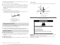
GAS DRYER
USE & CARE GUIDE
FOR QUESTIONS ABOUT FEATURES, OPERATION/PERFORMANCE, PARTS, ACCESSORIES OR SERVICE CALL: 1.800.688.9900
VISIT OUR WEBSITE AT WWW.MAYTAG.COM
W10155111A
TABLE OF CONTENTS
DRYER SAFETY........................................................................................................................2
INSTALLATION INSTRUCTIONS ...........................................................................................5
Tools and Parts.....................................................................................................................5
Location Requirements ........................................................................................................5
Electrical Requirements........................................................................................................7
Gas Supply Requirements ....................................................................................................7
Venting Requirements ..........................................................................................................8
Plan Vent System............................................................................................................... 10
Install Vent System ............................................................................................................ 11
Install Leveling Legs .......................................................................................................... 11
Make Gas Connection....................................................................................................... 12
Connect Vent .................................................................................................................... 12
Level Dryer ....................................................................................................................... 12
Complete Installation ........................................................................................................ 13
DRYER USE........................................................................................................................... 14
Starting Your Dryer............................................................................................................ 14
Drying Rack ...................................................................................................................... 15
DRYER CARE ....................................................................................................................... 15
Cleaning the Dryer Location ............................................................................................. 15
Cleaning the Lint Screen ................................................................................................... 15
Cleaning the Dryer Interior................................................................................................ 16
Removing Accumulated Lint ............................................................................................. 16
Vacation and Moving Care................................................................................................ 16
Changing the Drum Light .................................................................................................. 16
TROUBLESHOOTING.......................................................................................................... 17
ASSISTANCE OR SERVICE.................................................................................................... 19
ACCESSORIES....................................................................................................................... 19
WARRANTY ......................................................................................................................... 20
DRYER SAFETY
Your safety and the safety of others are very important.
We have provided many important safety messages in this manual and on your appliance. Always read and obey all safety
messages.
This is the safety alert symbol.
This symbol alerts you to potential hazards that can kill or hurt you and others.
All safety messages will follow the safety alert symbol and either the word “DANGER” or “WARNING.”
These words mean:
DANGER
WARNING
You can be killed or seriously injured if you don't immediately
follow instructions.
You can be killed or seriously injured if you don't follow
instructions.
All safety messages will tell you what the potential hazard is, tell you how to reduce the chance of injury, and tell you what can
happen if the instructions are not followed.
2
WARNING: For your safety, the information in this manual must be followed to minimize
the risk of fire or explosion, or to prevent property damage, personal injury, or death.
– Do not store or use gasoline or other flammable vapors and liquids in the vicinity of this
or any other appliance.
– WHAT TO DO IF YOU SMELL GAS:
• Do not try to light any appliance.
• Do not touch any electrical switch; do not use any phone in your building.
• Clear the room, building, or area of all occupants.
• Immediately call your gas supplier from a neighbor's phone. Follow the gas supplier's
instructions.
• If you cannot reach your gas supplier, call the fire department.
– Installation and service must be performed by a qualified installer, service agency, or
the gas supplier.
In the State of Massachusetts, the following installation instructions apply:
■
■
■
Installations and repairs must be performed by a qualified or licensed contractor, plumber, or gasfitter qualified or licensed by
the State of Massachusetts.
If using a ball valve, it shall be a T-handle type.
A flexible gas connector, when used, must not exceed 3 feet.
3
IMPORTANT SAFETY INSTRUCTIONS
WARNING: To reduce the risk of fire, electric shock, or injury to persons when using the dryer, follow basic precautions,
including the following:
■
■
■
■
■
■
■
■
Read all instructions before using the dryer.
Do not place items exposed to cooking oils in your dryer.
Items contaminated with cooking oils may contribute to
a chemical reaction that could cause a load to catch fire.
Do not dry articles that have been previously cleaned in,
washed in, soaked in, or spotted with gasoline, drycleaning solvents, or other flammable or explosive
substances as they give off vapors that could ignite or
explode.
Do not allow children to play on or in the dryer. Close
supervision of children is necessary when the dryer is
used near children.
Before the dryer is removed from service or discarded,
remove the door to the drying compartment.
Do not reach into the dryer if the drum is moving.
Do not install or store the dryer where it will be exposed
to the weather.
Do not tamper with controls.
■
■
■
■
■
■
■
Do not repair or replace any part of the dryer or attempt
any servicing unless specifically recommended in this
Use and Care Guide or in published user-repair
instructions that you understand and have the skills to
carry out.
Do not use fabric softeners or products to eliminate static
unless recommended by the manufacturer of the fabric
softener or product.
Do not use heat to dry articles containing foam rubber or
similarly textured rubber-like materials.
Clean lint screen before or after each load.
Keep area around the exhaust opening and adjacent
surrounding areas free from the accumulation of lint, dust,
and dirt.
The interior of the dryer and exhaust vent should be
cleaned periodically by qualified service personnel.
See installation instructions for grounding requirements.
SAVE THESE INSTRUCTIONS
IMPORTANT: The gas installation must conform with local codes, or in the absence of local codes, with the National Fuel Gas
Code, ANSI Z223.1/NFPA 54.
The dryer must be electrically grounded in accordance with local codes, or in the absence of local codes, with the National
Electrical Code, ANSI/NFPA 70.
4
INSTALLATION INSTRUCTIONS
Tools and Parts
Location Requirements
Gather the required tools and parts before starting installation. Read and follow the
instructions provided with any tools listed here.
■
8" or 10" pipe wrench
■
Level
■
8" or 10" adjustable
wrench (for gas
connections)
■
Knife
■
Vent clamps
■
Pipe-joint compound
resistant to LP gas
■
Caulking gun and
compound (for installing
new exhaust vent)
■
Flat-blade screwdriver
■
Adjustable wrench that
opens to 1" (2.5 cm) or
hex-head socket wrench
(for adjusting dryer feet)
■
¼" nut driver or socket
wrench (recommended)
■
Pliers
■
Tape measure
WARNING
Explosion Hazard
Keep flammable materials and vapors, such as
gasoline, away from dryer.
Place dryer at least 18 inches (46 cm) above the floor
for a garage installation.
Failure to do so can result in death, explosion, or fire.
Parts supplied:
Remove parts package from dryer drum. Check that all parts were included.
You will need
■
A location that allows for proper exhaust installation. A gas dryer must be exhausted to
the outdoors. See “Venting Requirements.”
■
A grounded electrical outlet located within 2 ft (61 cm) of either side of the dryer. See
“Electrical Requirements.”
■
A sturdy floor to support the dryer with a total weight (dryer and load) of 200 lbs (90.7 kg).
The combined weight of a companion appliance should also be considered.
■
A level floor with a maximum slope of 1" (2.5 cm) under entire dryer. (If slope is greater
than 1" [2.5 cm], install Extended Dryer Feet Kit, Part Number 279810.) Clothes may not
tumble properly and dryers with automatic sensor cycles may not operate correctly if
dryer is not level.
4 leveling legs
Parts needed:
Check local codes and consult gas supplier. Check existing gas supply, electrical supply and
venting, and read “Electrical Requirements,” “Gas Supply Requirements” and “Venting
Requirements” before purchasing parts.
Mobile home installations require special parts (listed following) that may be ordered by
calling the dealer from whom you purchased your dryer. For further information, please refer
to the “Assistance or Service” section.
■ Mobile Home Installation Kit. Ask for Part Number 346764.
■
Metal exhaust system hardware.
Do not operate your dryer at temperatures below 45ºF (7ºC). At lower temperatures, the dryer
might not shut off at the end of an automatic cycle. Drying times can be extended.
The dryer must not be installed or stored in an area where it will be exposed to water and/or
weather.
Check code requirements. Some codes limit, or do not permit, installation of the dryer in
garages, closets, mobile homes, or sleeping quarters. Contact your local building inspector.
NOTE: No other fuel-burning appliance can be installed in the same closet as a dryer.
5
Installation Clearances
■
Companion appliance spacing should also be considered.
The location must be large enough to allow the dryer door to open fully.
Dryer Dimensions
14" max.*
(35.6cm)
18"*
(45.7 cm)
43 ½"
(110.5 cm)
48 in.2 *
2
(310 cm )
24 in.2 *
2
(155 cm )
1"
(2.5 cm)
27"
(68.6 cm)
*Most installations require a minimum 5" (12.7 cm) clearance behind the dryer for the
exhaust vent with elbow. See “Venting Requirements.”
Installation spacing for recessed area or closet installation
The following spacing dimensions are recommended for this dryer. This dryer has been tested
for spacing of 0" (0 cm) clearance on the sides and rear. Recommended spacing should be
considered for the following reasons:
■ Additional spacing should be considered for ease of installation and servicing.
■
Additional clearances might be required for wall, door and floor moldings.
■
Additional spacing should be considered on all sides of the dryer to reduce noise transfer.
■
For closet installation, with a door, minimum ventilation openings in the top and bottom
of the door are required. Louvered doors with equivalent ventilation openings are
acceptable.
27"
(68.6 cm)
A
14 ³⁄₁₆"
(36 cm)
*29 ¼"
(74.3 cm)
6
3"*
(7.6 cm)
3"*
(7.6 cm)
1"* 29¼"
1"
5"
(2.5 cm) (2.5 cm) (74.3 cm) (14 cm)
B
C
A. Recessed area
B. Side view - closet or confined area
C. Closet door with vents
*Required spacing
Mobile Home - Additional Installation Requirements
This dryer is suitable for mobile home installations.
The installation must conform to the Manufactured Home Construction and Safety Standard,
Title 24 CFR, Part 3280 (formerly the Federal Standard for Mobile Home Construction and
Safety, Title 24, HUD Part 280).
Mobile home installations require:
■ Metal exhaust system hardware, which is available for purchase from your dealer.
■
Mobile home Installation Kit Part Number 346764. See “Tools and Parts” section for
information on ordering.
■
Special provisions must be made in mobile homes to introduce outside air into the dryer.
The opening (such as a nearby window) should be at least twice as large as the dryer
exhaust opening.
Electrical Requirements
Gas Supply Requirements
WARNING
WARNING
Explosion Hazard
Electrical Shock Hazard
Plug into a grounded 3 prong outlet.
Use a new CSA International approved gas supply line.
Do not remove ground prong.
Install a shut-off valve.
Do not use an adapter.
Securely tighten all gas connections.
Do not use an extension cord.
If connected to LP, have a qualified person make sure
gas pressure does not exceed 13" (33 cm) water
column.
Failure to follow these instructions can result in death,
fire, or electrical shock.
■
Examples of a qualified person include:
licensed heating personnel,
authorized gas company personnel, and
authorized service personnel.
120 Volt, 60 Hz., AC only, 15- or 20-amp fused electrical supply is required. A time-delay
fuse or circuit breaker is recommended. It is also recommended that a separate circuit
serving only this dryer be provided.
Failure to do so can result in death, explosion, or fire.
GROUNDING INSTRUCTIONS
Gas Type
■
For a grounded, cord-connected dryer:
This dryer must be grounded. In the event of malfunction or
breakdown, grounding will reduce the risk of electric shock
by providing a path of least resistance for electric current.
This dryer is equipped with a cord having an equipmentgrounding conductor and a grounding plug. The plug must
be plugged into an appropriate outlet that is properly
installed and grounded in accordance with all local codes
and ordinances.
WARNING: Improper connection of the equipmentgrounding conductor can result in a risk of electric shock.
Check with a qualified electrician or service representative
or personnel if you are in doubt as to whether the dryer is
properly grounded. Do not modify the plug provided with the
dryer: if it will not fit the outlet, have a proper outlet installed
by a qualified electrician.
SAVE THESE INSTRUCTIONS
Natural Gas:
This dryer is equipped for use with Natural gas. It is design-certified by CSA International for
LP (propane or butane) gases with appropriate conversion.
■ Your dryer must have the correct burner for the type of gas in your home. Burner
information is located on the rating plate in the door well of your dryer. If this information
does not agree with the type of gas available, contact your dealer or call the phone
numbers referenced on the front page of this manual.
LP gas conversion:
Conversion must be made by a qualified technician.
No attempt shall be made to convert the appliance from the gas specified on the model/serial
rating plate for use with a different gas without consulting your gas company.
Gas supply line
■
Must include ¹⁄₈" NPT minimum plugged tapping accessible for test gauge connection,
immediately upstream of the gas connection to the dryer. See illustration.
■
¹⁄₂" IPS pipe is recommended.
7
■
³⁄₈" approved aluminum or copper tubing is acceptable for lengths under 20 ft (6.1 m) if
local codes and gas supplier permit.
■
If you are using Natural gas, do not use copper tubing.
■
Lengths over 20 ft (6.1 m) should use larger tubing and a different size adapter fitting.
■
If your dryer has been converted to use LP gas, ³⁄₈" LP compatible copper tubing can be
used. If the total length of the supply line is more than 20 ft (6.1 m), use larger pipe.
Dryer Gas Pipe
■
The gas pipe that comes out through the rear of your dryer has a ³⁄₈" male pipe thread.
6¼"
(15.88 cm)
NOTE: Pipe-joint compounds that resist the action of LP gas must be used. Do not use
TEFLON®† tape.
■
B
Must include a shutoff valve:
An individual shutoff valve must be installed within 6 feet
(1.8 m) of the dryer in accordance with the National Fuel Gas Code, ANSI Z223.1. The
location should be easy to reach for opening and closing.
C
A
1½"
(3.81 cm)
A
E
A. ½" NPT gas supply line
B. ³⁄₈" NPT dryer pipe
B
D
A. ³⁄₈" flexible gas connector
B. ³⁄₈" pipe to flare adapter fitting
C. ¹⁄₈" NPT minimum plugged tapping
D. ½" NPT gas supply line
E. Gas shutoff valve
Venting Requirements
WARNING
Gas supply connection requirements
■
Use an elbow and a ³⁄₈" flare x ³⁄₈" NPT adapter fitting between the flexible gas connector
and the dryer gas pipe, as needed to avoid kinking.
■
Use only pipe-joint compound. Do not use TEFLON®† tape.
■
This dryer must be connected to the gas supply line with a listed flexible gas connector
that complies with the standard for connectors for gas appliances, ANSI Z21.24.
Burner input requirements
Elevations above 10,000 ft (3,048 m):
■ When installed above 10,000 ft (3,048 m) a 4% reduction of the burner Btu rating shown
on the model/serial number plate is required for each 1,000 ft (305 m) increase in
elevation.
Gas supply pressure testing
■
The dryer must be disconnected from the gas supply piping system during pressure testing
at pressures greater than ½ psi.
†®TEFLON is a registered trademark of E.I. Du Pont De Nemours and Company.
8
Fire Hazard
Use a heavy metal vent.
Do not use a plastic vent.
Do not use a metal foil vent.
Failure to follow these instructions can result in death
or fire.
WARNING: To reduce the risk of fire, this dryer MUST BE EXHAUSTED OUTDOORS.
IMPORTANT: Observe all governing codes and ordinances.
The dryer exhaust must not be connected into any gas vent, chimney, wall, ceiling or a
concealed space of a building.
Clamps
Use clamps to seal all joints.
If using an existing vent system
■
■
Clean lint from the entire length of the system and make sure exhaust hood is not plugged
with lint.
■
Replace any plastic or metal foil vent with rigid or flexible heavy metal vent.
■
Review Vent system chart. Modify existing vent system if necessary to achieve the best
drying performance.
■
Exhaust vent must not be connected or secured with screws or other fastening devices
that extend into the interior of the duct. Do not use duct tape.
Clamp
If this is a new vent system
Exhaust
Recommended hood styles are shown here.
Vent material
■
Use a heavy metal vent. Do not use plastic or metal foil vent.
■
4" (10.2 cm) heavy metal exhaust vent and clamps must be used.
B
A
4"
(10.2 cm)
4"
10.2 cm
4"
(10.2 cm)
4" (10.2 cm) heavy metal exhaust vent
A. Louvered hood style
B. Box hood style
Vent products can be purchased from your dealer or by calling Maytag Services. For more
information, see the “Assistance or Service” section.
The angled hood style (shown here) is acceptable.
Rigid metal vent
■ For best drying performance, rigid metal vents are recommended.
■
4"
(10.2 cm)
Rigid metal vent is recommended to avoid crushing and kinking.
Flexible metal vent
■ Flexible metal vents are acceptable only if accessible for cleaning.
■
Flexible metal vent must be fully extended and supported when the dryer is in its final
location.
■
Remove excess flexible metal vent to avoid sagging and kinking that may result in
reduced airflow and poor performance.
■
Do not install flexible metal vent in enclosed walls, ceilings or floors.
Elbows
45° elbows provide better airflow than 90° elbows.
2½"
(6.4 cm)
■
An exhaust hood should cap the vent to keep rodents and insects from entering the home.
■
Exhaust hood must be at least 12" (30.5 cm) from the ground or any object that may be in
the path of the exhaust (such as flowers, rocks or bushes, snow line, etc.).
■
Do not use an exhaust hood with a magnetic latch.
Improper venting can cause moisture and lint to collect
indoors, which may result in:
Moisture damage to woodwork, furniture, paint, wallpaper,
carpets, etc.
Housecleaning problems and health problems.
Good
Better
9
Plan Vent System
Choose your exhaust installation type
Recommended exhaust installations
Typical installations vent the dryer from the rear of the dryer. Other installations are possible.
B
A
C
D
C
A. Standard rear offset exhaust installation
B. Left or right side exhaust installation
C. Bottom exhaust installation
E
A
B
F
Alternate installations for close clearances
G
Venting systems come in many varieties. Select the type best for your installation. Two closeclearance installations are shown. Refer to the manufacturer’s instructions.
B
H
A. Dryer
B. Elbow
C. Wall
D. Exhaust hood
E. Clamps
F. Rigid metal or flexible metal vent
G. Vent length necessary to connect elbows
H. Exhaust outlet
Optional exhaust installations
A
This dryer can be converted to exhaust out the right side, left side, or through the bottom. If
you prefer, you may contact your local dealer to have the dryer converted.
WARNING
B
A. Over-the-top installation (also available with one offset elbow)
B. Periscope installation
NOTE: The following kits for close clearance alternate installations are available for purchase.
To order, please see the “Assistance or Service” section.
■ Over-the-Top Installation:
Part Number 4396028
■
Periscope Installation (For use with dryer vent to wall vent mismatch):
Part Number 4396037 - 0" (0 cm) to 18" (45.72 cm) mismatch
Fire Hazard
Cover unused exhaust holes with the following kit:
279818 (white)
Contact your local dealer.
Failure to follow these instructions can result in death,
fire, electrical shock, or serious injury.
10
Part Number 4396011 - 18" (45.72 cm) to 29" (73.66 cm) mismatch
Part Number 4396014 - 29" (73.66 cm) to 50" (127 cm) mismatch
Special provisions for mobile home installations
The exhaust vent must be securely fastened to a noncombustible portion of the mobile home
structure and must not terminate beneath the mobile home. Terminate the exhaust vent
outside.
Determine vent path
■
Select the route that will provide the straightest and most direct path outdoors.
■
Plan the installation to use the fewest number of elbows and turns.
■
When using elbows or making turns, allow as much room as possible.
■
Bend vent gradually to avoid kinking.
■
Use the fewest 90° turns possible.
Determine vent length and elbows needed for best drying performance
■
Use the Vent system chart below to determine type of vent material and hood
combinations acceptable to use.
NOTE: Do not use vent runs longer than those specified in the Vent system chart. Exhaust
systems longer than those specified will:
■
Shorten the life of the dryer.
■
Reduce performance, resulting in longer drying times and increased energy usage.
The Vent system chart provides venting requirements that will help to achieve the best drying
performance.
Vent system chart
NOTE: Side and bottom exhaust installations have a 90º turn inside the dryer. To determine
maximum exhaust length, add one 90º turn to the chart.
Number of
90º turns
or elbows
Type of
vent
Box or
louvered
hoods
Angled
hoods
0
Rigid metal
Flexible metal
64 ft (20 m)
36 ft (11 m)
58 ft (17.7 m)
28 ft (8.5 m)
1
Rigid metal
Flexible metal
54 ft (16.5 m)
31 ft (9.4 m)
48 ft (14.6 m)
23 ft (7 m)
2
Rigid metal
Flexible metal
44 ft (13.4 m)
27 ft (8.2 m)
38 ft (11.6 m)
19 ft (5.8 m)
3
Rigid metal
Flexible metal
35 ft (10.7 m)
25 ft (7.6 m)
29 ft (8.8 m)
17 ft (5.2 m)
4
Rigid metal
Flexible metal
27 ft (8.2 m)
23 ft (7 m)
21 ft (6.4 m)
15 ft (4.6 m)
Install Vent System
1. Install exhaust hood. Use caulking compound to seal exterior wall opening around
exhaust hood.
2. Connect vent to exhaust hood. Vent must fit inside exhaust hood. Secure vent to exhaust
hood with 4" (10.2 cm) clamp.
3. Run vent to dryer location. Use the straightest path possible. See “Determine vent path” in
“Plan Vent System.” Avoid 90º turns. Use clamps to seal all joints. Do not use duct tape,
screws or other fastening devices that extend into the interior of the vent to secure vent.
Install Leveling Legs
WARNING
Excessive Weight Hazard
Use two or more people to move and install dryer.
Failure to do so can result in back or other injury.
1. To protect the floor, use a large flat piece of cardboard from the dryer carton. Place
cardboard under the entire back edge of the dryer.
11
2. Firmly grasp the body of the dryer (not the top or console panel). Gently lay the dryer on
the cardboard. See illustration.
A combination of pipe fittings must be used to connect the dryer to the existing gas line.
Shown is a recommended connection. Your connection may be different, according to the
supply line type, size and location.
D
3. Examine the leveling legs. Find the diamond marking.
A
B
4. Screw the legs into the leg holes by hand. Use a wrench to finish turning the legs until the
diamond marking is no longer visible.
5. Place a carton corner post from dryer packaging under each of the 2 dryer back corners.
Stand the dryer up. Slide the dryer on the corner posts until it is close to its final location.
Leave enough room to connect the exhaust vent or gas line.
For mobile home use
C
A. ³⁄₈" flexible gas connector
B. ³⁄₈" dryer pipe
C. ³⁄₈" to ³⁄₈" pipe elbow
D. ³⁄₈" pipe-to-flare adapter fitting
3. Open the shutoff valve in the supply line. The valve is open when the handle is parallel to
the gas pipe.
A
Gas dryers must be securely fastened to the floor.
B
A. Closed valve
B. Open valve
Mobile home installations require a Mobile Home Installation Kit. See “Tools and Parts”
section for information on ordering.
Make Gas Connection
1. Remove the red cap from the gas pipe.
2. Using a wrench to tighten, connect the gas supply to the dryer. Use pipe-joint compound
on the threads of all non-flared male fittings. If flexible metal tubing is used, be sure there
are no kinks.
A
B
4. Test all connections by brushing on an approved noncorrosive leak-detection solution.
Bubbles will show a leak. Correct any leak found.
Connect Vent
1. Using a 4" (10.2 cm) clamp, connect vent to exhaust outlet in dryer. If connecting to
existing vent, make sure the vent is clean. The dryer vent must fit over the dryer exhaust
outlet and inside the exhaust hood. Check that the vent is secured to exhaust hood with a
4" (10.2 cm) clamp.
2. Move dryer into its final location. Do not crush or kink vent.
3. (On gas models) Check that there are no kinks in the flexible gas line.
4. Once the exhaust vent connection is made, remove the corner posts and cardboard.
Level Dryer
Check the levelness of the dryer. Check levelness first side to side, then front to back.
A. Flared male fitting
B. Non-flared male fitting
NOTE: For LP gas connections, you must use pipe-joint compound resistant to the action
of LP gas. Do not use TEFLON®† tape.
†®TEFLON is a registered trademark of E.I. Du Pont De Nemours and Company.
12
If the dryer is not level, prop up the dryer using a wood block. Use a wrench to adjust the legs
up or down and check again for levelness.
Complete Installation
1. Check that all parts are now installed. If there is an extra part, go back through the steps to
see which step was skipped.
2. Check that you have all of your tools.
3. Check the dryer’s final location. Be sure the vent is not crushed or kinked.
4. Check that the dryer is level. See “Level Dryer.”
WARNING
Electrical Shock Hazard
Plug into a grounded 3 prong outlet.
Do not remove ground prong.
Do not use an adapter.
6. Remove any protective film on the console and any tape remaining on the dryer.
7. Dispose of/recycle all packaging materials.
8. Read “Dryer Use.”
9. Wipe the dryer drum interior thoroughly with a damp cloth to remove any dust.
10. Select a Timed Dry heated cycle, and start the dryer. Do not select the Air Only
Temperature setting.
If the dryer will not start, check the following:
■
Dryer is plugged into a grounded 3 prong outlet.
■
Electrical supply is connected.
■
Household fuse is intact and tight, or circuit breaker has not tripped.
■
Dryer door is closed.
11. When the dryer has been running for 5 minutes, open the dryer door and feel for heat. If
you feel heat, cancel cycle and close door. If you do not feel heat, turn off the dryer and
check that the gas supply line shutoff valve is open.
■ If the gas supply line shutoff valve is closed, open it, then repeat the 5-minute test as
outlined above.
■
If the gas supply line shutoff valve is open, contact a qualified technician.
Do not use an extension cord.
Failure to follow these instructions can result in death,
fire, or electrical shock.
5. Plug into a grounded 3 prong outlet. Turn on power.
13
DRYER USE
Starting Your Dryer
WARNING
WARNING
Explosion Hazard
Keep flammable materials and vapors, such as
gasoline, away from dryer.
Do not dry anything that has ever had anything
flammable on it (even after washing).
Failure to follow these instructions can result in death,
explosion, or fire.
This book covers several different models. Your dryer may not have all of the cycles and
features described.
Before using your dryer, wipe the dryer drum with a damp cloth to remove dust from storing
and shipping.
1. Clean lint screen before each load. See “Cleaning the Lint Screen.”
2. Load clothes loosely into the dryer and close the door. Do not pack the dryer. Allow space
for clothes to tumble freely.
3. Turn the Cycle Control knob to the recommended cycle for the type of load being dried.
ENERGY PREFERRED Sensor Dry setting is indicated on the timer dial, between the words
MORE DRY and LESS DRY. Use this ENERGY PREFERRED cycle to dry most heavy- to
medium-weight fabrics.
4. Set the Temperature control to the recommended setting for the type of fabric being dried.
See Dryer Cycle Descriptions (separate sheet) for temperature suggestions.
5. (OPTIONAL) Your dryer may have a WRINKLE PREVENT feature selector. When you are
unable to remove a load from the dryer as soon as it stops, wrinkles can form. This feature
periodically tumbles, rearranges and fluffs the load without heat to help avoid wrinkling.
6. (OPTIONAL) If you want the dryer to sound a signal when the cycle is finished, set the
END OF CYCLE SIGNAL control to ON. The signal is helpful when you are drying
permanent press, synthetics and other items that should be removed from the dryer as
soon as it stops.
7. If desired, add a fabric softener sheet. Follow package instructions.
14
Fire Hazard
No washer can completely remove oil.
Do not dry anything that has ever had any type of oil on
it (including cooking oils).
Items containing foam, rubber, or plastic must be dried
on a clothesline or by using an Air Cycle.
Failure to follow these instructions can result in death
or fire.
8. Press the PUSH TO START button.
Stopping and Restarting
You can stop your dryer anytime during a cycle.
To stop your dryer
Open the dryer door or turn the Cycle Control knob to OFF.
NOTE: The Cycle Control knob should point to an Off area when the dryer is not in use.
To restart your dryer
1. Close the door.
2. Select a new cycle and temperature (if desired).
3. Press the PUSH TO START button.
How Sensor Dry Works
When you are using the Sensor Dry Cycle, the dryness of the load is determined by two metal
strips (sensors) located on the inside of the dryer. The metal strips help “feel” the amount of
moisture left in the clothes as they tumble. When moisture is left in the clothes, the Cycle
Control knob will not advance. As clothes begin to dry, the amount of water left in the clothes
decreases, and the timer advances through the remainder of the cycle. When the selected
dryness level is reached, the dryer goes into a cool down period of up to 10 minutes.
Drying Rack
The drying rack is useful for machine drying items you would not necessarily want to tumble
dry (for example, sweaters).
If your model does not have a drying rack, you may be able to purchase one for your model.
To find out whether your model allows drying rack usage and for information on ordering,
please refer to the front page of the manual or contact the dealer from whom you purchased
your dryer.
To use the drying rack
1. Do not remove the lint screen.
2. Slide drying rack over the bottom of the dryer door opening. Push down to secure rack on
frame.
DRYER CARE
Cleaning the Dryer Location
Keep dryer area clear and free from items that would obstruct the flow of combustion and
ventilation air.
WARNING
Explosion Hazard
Keep flammable materials and vapors, such as
gasoline, away from dryer.
3. Put the wet items on top of the rack. Leave space between the items so air can reach all
the surfaces. Close the door.
NOTE: Do not allow items to hang over the edge of the rack.
4. Select a timed drying cycle and temperature, or an air cycle. Items containing foam,
rubber, or plastic must be dried on a clothesline or by using an air cycle.
5. Press the PUSH TO START button.
NOTE: You must remove the drying rack for normal tumbling. Do not use Sensor Dry cycles
with the drying rack.
This chart shows examples of items that can be rack dried and the suggested cycle,
temperature setting and drying time. Actual drying time will depend on the amount of
moisture items hold.
Rack Dry
Cycle
Temp
Time*
Wool Sweaters
Block to shape and lay flat on the rack
Timed
Low
60
Stuffed toys or pillows
Cotton or polyester fiber filled
Timed
Low
60
Stuffed toys or pillows
Foam rubber filled
Timed
Air
(no heat)
90
Sneakers or canvas shoes
Timed
Air
(no heat)
90
Place dryer at least 18 inches (46 cm) above the floor
for a garage installation.
Failure to do so can result in death, explosion, or fire.
Cleaning the Lint Screen
Clean lint screen before each load. A screen blocked by lint can increase drying time.
IMPORTANT:
■ Do not run the dryer with the lint screen loose, damaged, blocked or missing. Doing so
can cause overheating and damage to both the dryer and fabrics.
■
If lint falls off the screen into the dryer during removal, check the exhaust hood and
remove the lint.
Every Load Cleaning
1. The lint screen is located in the door of the dryer. Pull the lint screen straight up. Roll lint
off the screen with your fingers. Do not rinse or wash screen to remove lint. Wet lint is
hard to remove.
*(Minutes) Reset time to complete drying, if needed.
2. Push the lint screen firmly back into place.
15
Vacation and Moving Care
As Needed Cleaning
1. Roll lint off the screen with your fingers.
2. Wet both sides of lint screen with hot water.
3. Wet a nylon brush with hot water and liquid detergent. Scrub lint screen with the brush to
remove residue buildup.
4. Rinse screen with hot water.
5. Thoroughly dry lint screen with a clean towel. Replace screen in dryer.
Cleaning the Dryer Interior
1. Apply a liquid, nonflammable household cleaner to the stained area of the drum and rub
with a soft cloth until stain is removed.
2. Wipe drum thoroughly with a damp cloth.
3. Tumble a load of clean cloths or towels to dry the drum.
NOTE: Garments that contain unstable dyes, such as denim blue jeans or brightly colored
cotton items, may discolor the dryer interior. These stains are not harmful to your dryer and
will not stain future loads of clothes. Dry unstable dye items inside-out to avoid transfer of
dye.
Removing Accumulated Lint
From Inside the Dryer Cabinet
Lint should be removed every 2 years, or more often, depending on dryer usage. Cleaning
should be done by a qualified person.
Vacation care
Operate your dryer only when you are at home. If you will be on vacation or not using your
dryer for an extended period of time, you should:
1. Unplug dryer or disconnect power.
2. Close shutoff valve in gas supply line.
3. Clean lint screen. See “Cleaning the Lint Screen.”
Moving care
1.
2.
3.
4.
5.
6.
Unplug the power supply cord.
Close shutoff valve in gas supply line.
Disconnect gas supply line pipe and remove fittings attached to dryer pipe.
Cap the open fuel supply line.
Make sure leveling legs are secure in dryer base.
Use masking tape to secure dryer door.
Changing the Drum Light
1. Unplug dryer or disconnect power.
2. Open the dryer door. Locate the light bulb cover on the back wall of the dryer. Remove
the screw located in the lower right-hand corner of the cover. Remove the cover.
From the Exhaust Vent
Lint should be removed every 2 years, or more often, depending on dryer usage.
3. Turn bulb counterclockwise. Replace the bulb with a 10-watt appliance bulb only.
Replace the cover and secure with the screw.
4. Plug in dryer or reconnect power.
16
TROUBLESHOOTING
First try the solutions suggested here or visit our website and reference FAQs (Frequently Asked Questions) to possibly avoid the cost of a service call...
In U.S.A www.maytag.com/help - In Canada www.maytag.ca
Dryer Operation
Dryer will not run
■
Has a household fuse blown, or has a circuit breaker tripped?
Replace the fuse or reset the circuit breaker. If the problem continues, call an electrician.
■
Was a regular fuse used?
Use a time-delay fuse.
■
Is the dryer door firmly closed?
■
Was the Start button firmly pressed?
■
Is a cycle selected?
The dryer will not start in the Wrinkle Prevent position. Move the dial past OFF.
Timer does not noticeably advance
■
Is the dryer set to Timed Dry?
The timer moves slowly and continuously for the time setting.
■
Is the dryer set to Sensor Dry?
The timer moves only when the clothing is mostly dry. See “How Sensor Dry Works” in
“Dryer Use.”
Dryer Results
Clothes are not drying satisfactorily, drying times are too long, or load is too hot
■
No heat
■
Has a household fuse blown, or has a circuit breaker tripped?
The drum may be turning, but you may not have heat. Replace the fuse or reset the circuit
breaker. If the problem continues, call an electrician.
■
Is the valve open on the gas supply line?
Is the lint screen clogged with lint?
Lint screen should be cleaned before each load.
WARNING
Unusual sounds
Fire Hazard
■
■
Has the dryer had a period of non-use?
If the dryer hasn’t been used for a while, there may be a thumping sound during the first
few minutes of operation.
Use a heavy metal vent.
Do not use a plastic vent.
Is a coin, button, or paper clip caught between the drum and front or rear of the dryer?
Check the front and rear edges of the drum for small objects. Clean out pockets before
laundering.
■
Is it a gas dryer?
The gas valve clicking is a normal operating sound.
■
Are the four legs installed, and is the dryer level front to back and side to side?
The dryer may vibrate if not properly installed. See the Installation Instructions.
■
Is the clothing knotted or balled up?
When balled up, the load will bounce, causing the dryer to vibrate. Separate the load
items and restart the dryer.
Do not use a metal foil vent.
Failure to follow these instructions can result in death
or fire.
■
Is the exhaust vent or outside exhaust hood clogged with lint, restricting air movement?
Run the dryer for 5-10 minutes. Hold your hand under the outside exhaust hood to check
air movement. If you do not feel air movement, clean exhaust system of lint or replace
exhaust vent with heavy metal or flexible metal vent. See the Installation Instructions.
■
Are fabric softener sheets blocking the grille?
Use only one fabric softener sheet, and use it only once.
■
Is the exhaust vent the correct length?
Check that the exhaust vent is not too long or has too many turns. Long venting will
increase drying times. See the Installation Instructions.
17
■
Is the exhaust vent diameter the correct size?
Use 4" (10.2 cm) diameter vent material.
Cycle time too short
WARNING
WARNING
Excessive Weight Hazard
Use two or more people to move and install dryer.
Failure to do so can result in back or other injury.
Explosion Hazard
■
Keep flammable materials and vapors, such as
gasoline, away from dryer.
Change the dryness level setting on Sensor Dry cycles. Increasing or decreasing the
dryness level will change the amount of drying time in a cycle.
Place dryer at least 18 inches (46 cm) above the floor
for a garage installation.
Lint on load
Failure to do so can result in death, explosion, or fire.
■
■
Is the dryer located in a room with temperature below 45ºF (7ºC)?
Proper operation of dryer cycles requires temperatures above 45ºF (7ºC).
■
Is the dryer located in a closet?
Closet doors must have ventilation openings at the top and bottom of the door. Sides and
front of dryer require a minimum of 1" (2.5 cm) of airspace, and the rear of the dryer
requires 5" (12.7 cm). See the Installation Instructions.
■
■
Is the Sensor Dry cycle ending early?
The load may not be contacting the sensor strips. Level the dryer.
Is the lint screen clogged?
Lint screen should be cleaned before each load.
Stains on load or drum
■
Has an air dry cycle been selected?
Select the right cycle for the types of garments being dried.
Was dryer fabric softener properly used?
Add dryer fabric softener sheets at the beginning of the cycle. Fabric softener sheets added
to a partially dried load can stain your garments.
Drum stains are caused by dyes in clothing (usually blue jeans). This will not transfer to
other clothing.
Is the load too large and heavy to dry quickly?
Separate the load to tumble freely.
Loads are wrinkled
■
Was the load removed from dryer at the end of the cycle?
■
Was the dryer overloaded?
Dry smaller loads that can tumble freely.
Odors
■
18
Have you recently been painting, staining or varnishing in the area where your dryer is
located?
If so, ventilate the area. When the odors or fumes are gone from the area, rewash and dry
the clothing.
ASSISTANCE OR SERVICE
Before calling for assistance or service, please check “Troubleshooting.” It may save you the
cost of a service call. If you still need help, follow the instructions below.
When calling, please know the purchase date and the complete model and serial number of
your appliance. This information will help us to better respond to your request.
If you need replacement parts
If you need to order replacement parts, we recommend that you use only factory specified
parts. Factory specified parts will fit right and work right because they are made with the same
precision used to build every new MAYTAG® appliance.
To locate factory specified parts in your area, call the following customer assistance telephone
number or your nearest designated service center.
In the U.S.A.
Call Maytag Services, LLC Customer Assistance toll free: 1-800-688-9900, or vist our website
at www.maytag.com
Our consultants provide assistance with:
■ Features and specifications on our full line of appliances.
■
Installation information.
■
Use and maintenance procedures.
■
Accessory and repair parts sales.
■
Specialized customer assistance (Spanish speaking, hearing impaired, limited vision,
etc.).
■
Referrals to local dealers, repair parts distributors and service companies. Maytag®
appliances designated service technicians are trained to fulfill the product warranty and
provide after-warranty service, anywhere in the United States.
ACCESSORIES
Enhance your dryer with these premium accessories.
For more high-quality items or to order, call 1-800-901-2042, or visit us at
www.maytag.com/accessories.
Part Number
20-48KITRC
PT220L
PT400L
PT600L
8212614
31682
1903WH
3404351
3406839
8212450
49971
49572
Accessory
4" (10.2 cm) gas line dryer connector installation kit
4" (10.2 cm) dryer cord, 3-wire, 30 amp
4" (10.2 cm) dryer cord, 4-wire, 30 amp
6" (15.2 cm) dryer cord, 4-wire, 30 amp
Dryer vent lint brush
All-purpose appliance cleaner
Laundry supply storage cart
Drying rack - fits 29" (73.7 cm) Super Capacity, 6.5 cu. ft (0.20 cu. m) side swing or hamper door
Drying rack - fits 29" (73.7 cm) Super Capacity Plus, 7.0 cu. ft (0.18 cu. m)
- side swing door only
Drying rack - fits 27" (68.6 cm) Ultra Capacity - side swing door only
Compact dryer stand - white
LP gas conversion kit
To locate the Maytag® appliances designated service company in your area, you can also
look in your telephone directory Yellow Pages.
For further assistance
If you need further assistance, you can write to Maytag® appliances with any questions or
concerns at:
Maytag Services, LLC
ATTN: CAIR® Center
P.O. Box 2370
Cleveland, TN 37320-2370
Please include a daytime phone number in your correspondence.
19
MAYTAG CORPORATION MAJOR APPLIANCE WARRANTY
ONE YEAR LIMITED WARRANTY
For one year from the date of purchase, when this major appliance is operated and maintained according to instructions attached to or furnished with the product, Maytag Corporation or
Maytag Limited (hereafter “Maytag”) will pay for Factory Specified Parts and repair labor to correct defects in materials or workmanship. Service must be provided by a Maytag designated
service company. This limited warranty applies only when the major appliance is used in the country in which it was purchased.
ITEMS MAYTAG WILL NOT PAY FOR
Service calls to correct the installation of your major appliance, to instruct you how to use your major appliance, to replace or repair house fuses or to correct house wiring or plumbing.
Service calls to repair or replace appliance light bulbs, air filters or water filters. Those consumable parts are excluded from warranty coverage.
Repairs when your major appliance is used for other than normal, single-family household use.
Damage resulting from accident, alteration, misuse, abuse, fire, flood, acts of God, improper installation, installation not in accordance with electrical or plumbing codes, or use of
products not approved by Maytag.
5. Any food loss due to refrigerator or freezer product failures.
6. Replacement parts or repair labor costs for units operated outside the United States or Canada.
7. Pickup and delivery. This major appliance is designed to be repaired in the home.
8. Repairs to parts or systems resulting from unauthorized modifications made to the appliance.
9. Expenses for travel and transportation for product service in remote locations.
10. The removal and reinstallation of your appliance if it is installed in an inaccessible location or is not installed in accordance with published installation instructions.
11. Replacement parts or repair labor costs when the major appliance is used in a country other than the country in which it was purchased.
1.
2.
3.
4.
DISCLAIMER OF IMPLIED WARRANTIES; LIMITATION OF REMEDIES
CUSTOMER'S SOLE AND EXCLUSIVE REMEDY UNDER THIS LIMITED WARRANTY SHALL BE PRODUCT REPAIR AS PROVIDED HEREIN. IMPLIED WARRANTIES, INCLUDING
WARRANTIES OF MERCHANTABILITY OR FITNESS FOR A PARTICULAR PURPOSE, ARE LIMITED TO ONE YEAR OR THE SHORTEST PERIOD ALLOWED BY LAW. MAYTAG SHALL
NOT BE LIABLE FOR INCIDENTAL OR CONSEQUENTIAL DAMAGES. SOME STATES AND PROVINCES DO NOT ALLOW THE EXCLUSION OR LIMITATION OF INCIDENTAL OR
CONSEQUENTIAL DAMAGES, OR LIMITATIONS ON THE DURATION OF IMPLIED WARRANTIES OF MERCHANTABILITY OR FITNESS, SO THESE EXCLUSIONS OR LIMITATIONS MAY
NOT APPLY TO YOU. THIS WARRANTY GIVES YOU SPECIFIC LEGAL RIGHTS AND YOU MAY ALSO HAVE OTHER RIGHTS, WHICH VARY FROM STATE TO STATE OR PROVINCE TO
PROVINCE.
Outside the 50 United States and Canada, this warranty does not apply. Contact your authorized Maytag dealer to determine if another warranty applies.
If you need service, first see the “Troubleshooting” section of the Use & Care Guide. After checking “Troubleshooting,” additional help can be found by checking the “Assistance or Service”
section or by calling Maytag. In the U.S.A., call 1-800-688-9900. In Canada, call 1-800-807-6777.
9/06
Keep this book and your sales slip together for future reference. You must provide
proof of purchase or installation date for in-warranty service.
Write down the following information about your major appliance to better help you obtain
assistance or service if you ever need it. You will need to know your complete model
number and serial number. You can find this information on the model and serial number
label located on the product.
Dealer name _____________________________________________________________________________
Address _________________________________________________________________________________
Phone number ___________________________________________________________________________
Model number ___________________________________________________________________________
Serial number ____________________________________________________________________________
Purchase date ___________________________________________________________________________
W10155111A
SP PN W10155112A
© 2007
All rights reserved.
®Registered Trademark/ ™ Trademark of Maytag Corporation or its related companies.
8/07
Printed in U.S.A.