1
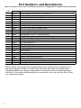
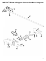
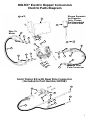
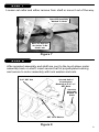
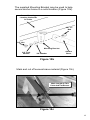
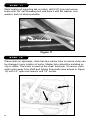
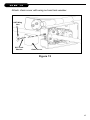
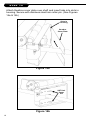
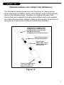
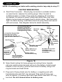
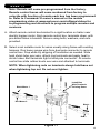
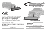
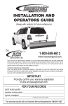
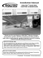
Installation Manual
ROLTECTM ELECTRIC
HOPPER CONVERSION
Thank you for purchasing a ROLTECTM Electric Hopper
Conversion system. ACI has manufactured this product
with pride using superior quality materials and strict quality
control manufacturing processes.
NOTICE TO INSTALLER:
It is recommended you take the time to read these instructions carefully
before installing or using this Electric Hopper Conversion. Often
improvements are made without prior notice. Always handle components
with care to avoid personal injury or damage to components. When done,
these instructions must be given to the end user.
NOTICE TO END USERS:
Read these instructions and understand this Electric Hopper Conversion
before using it. Store these instructions for future use.
Tested. Trusted. Guaranteed.
Inspection and Maintenance
• Periodic preventive maintenance should be practiced. Inspect system often
for proper operation.
• Periodically inspect all components for loose or worn parts and replace as
needed.
• Always use genuine Agri-Cover, Inc. replacement parts if repairs are needed.
• Periodically check the tightness of mounting bolts and electrical connections.
Remove any dirt or corrosion that may have accumulated on the electrical
connections.
• Do not attempt to disassemble the motor. Disassembly will void warranty.
• Periodically inspect chain tension and lubricate chain.
• Periodically grease zerk fittings.
• Perform routine maintenance on trailer hoppers to ensure optimal performance
from your system.
Safety
NOTE:
If original decal becomes damaged or missing, order
replacement decal part numbers 80503 or 80513.
ATTENTION:
- Open tarp before unloading
- Stay clear of moving parts
- Do not operate without shields
- Disconnect power to motor before servicing
PN 80503
2
PN 80513
Table of Contents
Inspection, Maintenance and Safety..................................................Page 2
Tools for Installation............................................................................Page 3
Part Numbers and Diagrams..............................................................Page 4-7
Installing Roltec Conversion...............................................................Page 8-15
Installing Electrical Parts....................................................................Page 16-21
Operating Instructions........................................................................Page 22
Manual Override.................................................................................Page 23
Warranty.............................................................................................Page 24
Tools
(most installations will require the following):
• Protective Eyewear
• Tape Measure
• Marking Pencil/Pen
• 3/8” Electric Drill
• 5/16” drill bit
• 3/16” Allen Wrench
• 1/2” socket
• 2 Vise Grip Pliers
• 9/16”, 1/2”, 7/16”
combination wrench
• Heat Gun
• Wire cutter and crimper
• Welder
•Grinder
• Hammer
3
Part Numbers and Descriptions
(item numbers are used to reference parts in diagrams throughout this manual)
Item
1
2
3
4
5
6
7
8
9
10
11
12
13
14
15
16
17
18
19
20
Part #
80210
80220
80230
80240
Description
Electric Hopper Conversion (1 Conversion)
Electric Hopper Conversion (2 Conversions)
Electric Hopper Conversion (3 Conversions)
Electric Hopper Conversion (4 Conversions)
80108
80222
80163
10921
10922
80091
80065
80194
80196
80160
80147
80186
80081
80153
80187
10893
10186
10903
10185
80162
80155
Semi/Trailer wire kit with dual pole connector
Motor/Gearbox Assembly
Set Collar
Nut, 5/16" Hex, GR 2, Stainless Steel
Washer Lock, 5/16", Stainless Steel
Polyethylene Bushing Assembly
Carriage Bolt, 5/16" x 1", Stainless Steel
Split Sprocket
Split Sprocket Hub
Gearbox Cover Plate
SST Hair Cotter Pin
Chain Cover
Wing Nut, 5/16", Stainless Steel
Drive Chain
Anchor Brace
Bolt, 3/8" x 1" Self Tapping HHD Zinc Plated
Nut, 3/8" Hex, Zinc Plated
Washer, 3/8" Lock Zinc Plated
Washer, 3/8" Flat, Zinc Plated
Mounting Bracket
Motor Cover (less motor)
NOTE: Some components are preassembled at the factory prior to shipping. The
exploded diagram at right is for reference purposes and does not display parts
in preassembled form. Always keep electric conversion parts in proper operating
condition. In the event replacement parts are needed, use only genuine Agri-Cover,
Inc. replacement parts.
4
ROLTECTM Electric Hopper Conversion Parts Diagram
18
17
16
17
18
15
19
16
15
14
9
13
8
5
4
4
2
3
6
3
10
7
4
12
1 20
11
5
Part Numbers and Descriptions
(item numbers are used to reference parts in diagrams throughout this manual)
Item
1
2
3
Part #
80239
80207
80235
Description
Wireless Control Box
Remote Key Fob w/ Lanyard
Bolt, 1/4” x 1-3/4’ GR 5, Zinc Plated
4
5
6
7
8
9
10
11
12
13
14
15
16
17
30212
30623
30625
60598
30650
70278
20046
60496
80197
10893
10185
10903
10186
80146
Washer, Flat 1/4”, Zinc Plated
Washer, Lock 1/4”, Zinc Plated
Nut, 1/4” hex, Zinc Plated
Eyelet Terminal Ring, 1/4”
Heat Shrink
Terminal boots, Lug Type 8-2 Ga.
Wire 6 Ga. 2 Strand
Eyelet Terminal Ring 5/16”
Remote Control Box Bracket
Bolt, 3/8” x 1” Self Tapping HHD, Zinc Plated
Washer, Flat 3/8”, Zinc Plated
Washer, Lock 3/8”, Zinc Plated
Nut, 3/8” Hex, Zinc Plated
Rubber grommet, 11/16’ (inside diameter)
The following items are included in Part Number 80180
Item
18
19
20
21
22
23
24
25
26
Part # Description
HD Dual Pole Connector Socket & Plug kit (200 amp) includes bolts, washers,
40918 and nuts
30647 Eyelet Terminal Ring 6 Ga. #10 (for automatic breaker)
30314 Eyelet Terminal Ring 6 Ga. 1/2" for Battery Post (+)
30313 Eyelet Terminal Ring 6 Ga. 3/8" for Battery Post (-)
10739 Circuit Breaker, Automatic 12V 40A
30648 Breaker Cover Red
30649 Heat Shink Kit
30312 Eyelet Terminal Ring 6 Ga. 5/16" for Dual Pole Terminals
20046 Wire 6 Ga. 2 Strand
Always keep electric conversion parts in proper operating condition.
In the event replacement parts are needed, use only genuine
Agri-Cover, Inc. replacement parts.
6
ROLTEC® Electric Hopper Conversion
Electric Parts Diagram
Shown Separate
for Diagram
Only, Comes
Pre-Assembled
in Control Box
13
12
2
Wire To
Motor
9
14
8
7
15
16
3
17
1
10
10
9
8
7
7
8
9
8
4
5
6
11
Wire To Dual
Pole Connector
Semi Trailer Kit with Dual Pole Connector
(Included in Part Number 80108)
20
18
25
19
21
24
22
23
26
7
STEP 1
NOTE: Prior to installing electric hopper conversion, perform all
necessary maintenance on hopper doors.
Hold drive box on crank shaft to determine best location for motor
based on ability to mount the anchor brace to a solid location. Motor
assembly must be square to shaft. NOTE: Mounting tab on Anchor
Brace may need to be bent to ensure proper connection. The
supplied Mounting Bracket may be used to help secure anchor
brace to a solid location (Items 15-19 on page 4 and 5)
Figure 1
STEP 2
Mark on shaft where attaching motor, document this location,
and make 2 additional marks 2 inches each direction on shaft from
original mark.
8
Figure 2
STEP 3
Between two additional marks made in previous step, clean shaft to bare
metal for welding and to insure overall diameter is 1”. NOTE: Ensure
shaft is clean at location of polyethylene bushing assembly. Once
shaft is clean replace 1st mark (documented in Step 2) back on shaft,
place set collar on outside of mark and secure to shaft with 3/16” Allen
Wrench.
Set Collar
Mark On Shaft
Clean S
haft
Figure 3
STEP 4
Place split sprocket and split sprocket hub adjacent to set collar and
assemble split sprocket hub (towards hopper) use carriage bolts,
lock washer and nuts to assemble.
Split Sprocket
Split Sprocket
Hub
5/16” x 1” SST
Carriage Bolt
SST Lock
Washer
5/16” SST Nut
Figure 4
9
STEP 5
Clamp sprocket assembly to set collar to ensure sprocket stays
square to drive shaft.
Sprocket Assembly
Set Collar
Hopper
Crank
Weld This Side
In Next Step
Figure 5
STEP 6
Weld sprocket assembly to drive shaft and let cool. Check sprocket
teeth for weld splatter, deburr if necessary.
Figure 6
10
STEP 7
Loosen set collar and either remove from shaft or move it out of the way.
Sprocket Assembly
Welded To Shaft
Move Or Remove
Set Collar To Be
Used Later
Figure 7
STEP 8
After sprocket assembly and shaft are cool to the touch place motor
assembly back on shaft, insert second half of polyethylene bushing
and secure to motor assembly with lock washer and nuts.
5/16” SST Nut
Second Half of
Polyethylene
Bushing w/ 5/16” x 1”
SST Bolts
Sprocket
Assembly
Welded To
Shaft
SST Lock Washer
Figure 8
11
STEP 9
Move set collar tight against plastic bushing to square up motor and
secure in place by tightening set screws, motor assembly will spin
freely on the shaft.
Move
Set Collar
Figure 9
STEP 10
Slide anchor brace into motor assembly. Mounting tab may need to be
bent to ensure a flat or secure fit at mounting location (Figure 10a).
Bend Mounting Tab
As Needed
Figure 10a
12
The supplied Mounting Bracket may be used to help
secure anchor brace to a solid location (Figure 10b).
Secure Mounting
Location Underside
Of Trailer
3/8” x 1”
Bolt
3/8” Nut
Mounting Bracket
3/8” Lock
Washer
Anchor
Brace
3/8” Washer
Figure 10b
Mark and cut off excess brace material (Figure 10c).
Mark Length At This
Point And Cut Excess
Figure 10c
13
STEP 11
Mark location of mounting tab on trailer, drill 5/16” hole and secure
brace with 3/8” self threading bolt and back it with flat washer, lock
washer, and nut where possible.
3/8” Self Threading Bolt
Figure 11
STEP 12
Place chain on sprockets, chain has two master links to ensure chain can
be changed in any location of motor. Master links should be installed so
clip is visible. The motor is used as the chain tensioner. To secure chain,
slide motor away from shaft and tighten three bolts (see arrows in Figure
12) with 1/2” open end wrench and 1/2” socket.
14
STEP 13
Attach chain cover with wing nut and lock washer.
SST Wing
Nut
SST Lock
Washer
Chain Cover
Figure 13
15
STEP 14
Attach Gearbox cover plate over shaft and insert tabs into slots in
housing. Secure with stainless steel hair cotter pin. (See Figures
14a & 14b)
Slots In
Housing
Gearbox
Cover Plate
Figure 14a
SST Hair
Cotter
Pin
Figure 14b
16
STEP 15
PREPARE WIRING FOR CONNECTOR TERMINALS.
The illustration below shows terminal ring sizes for heavy gauge
wires connecting to battery posts, circuit break, and motor terminals
used in the following steps. Insulation is stripped off ends, heat
shrink tubes are supplied for sealing and rubber boots are supplied
for control box terminals. Always measure wire lengths to ensure you
have plenty of wire when cutting and attaching terminals.
1/2 Eyelet For (+) Battery Post
3/8 Eyelet For (-) Battery Post
5/16 Eyelet For Circuit Breaker
And Motor Terminals
1/4 Eyelet For Solenoid Terminals
”
5/8
Typical For All Heavy
Gauge Wire Eyelets
Typical Heat
Shrink Tube For All
Heavy Gauge Wire
Connections
Rubber Terminal Boots
For Control Box and
Motor Connections
Figure 15
17
STEP 16
NOTE: If installing on trailer with existing electric tarp skip to step 17.
ELECTRIC WIRE ROUTING
A. Dual Pole Connector – Mount plug connector to suitable location
on semi-tractor, adjacent to existing plugs. Mount socket to
suitable location on trailer. Prep wires by stripping off insulation
as needed. On wires at socket, slide heat shrink tube over wire,
attach ring terminals and apply heat to shrink tubes. Bolt terminals
tight. On wires at plug, insert bare wires into plug tubes and secure
with set screws. See diagram below for detail assembly.
Thread Cutting Bolt 2x,
If Unable To Use Nut
Behind Frame Drill 1/4”
Hole And Turn Thread
Cutting Bolt Into Frame
Dual Pole
Socket
Flat
Washer
Lock
Washer
Nut
Loosen Set Screws Slide
Bare Wire Into Tubes –
Turn Both Set Screws
Tight Into Each Bare Wire
Bolts
For Ring
Terminals
Dual Pole Plug
Strip Wire Insulation
Off As Needed
Insert Wire
Retainer
Clip In Plug
As Shown
Red (+) Wire To (+)
Battery Terminal
Phillips Head
Screw At End Plug
Heat Shrink
Tube
Red Wire To Terminal
2 On Motor and
Terminal 2 on Remote
Control Box
Use Set SCREW
To Anchor Wire To
Plug Receptacle
Figure 16
B. Select best routing for heavy gauge wire along frame towards
cab near existing wire harness and up to the battery. Install circuit
breaker in line on red(+) positive wire close to battery using 5/16”
ring terminals and heat shrink.
C. Prep end of heavy black wire for battery (-) negative post with
heat shrink tube and 3/8” ring terminal. Prep end of heavy red
wire for battery (+) positive post with heat shrink tube and 1/2” ring
terminal. Do not connect wires to battery now.
18
STEP 17
Note: Remote will come pre-programmed from the factory.
Remote control boxes will come numbered from factory to
coincide with function of remote each box has been programmed
to. Refer to Command-10 owner’s manual or the remote
programming video at www.agricover.com/rolltarps/videos for
re-programming and directions to program multiple remotes and
receivers.
A. Attach remote control box bracket to a rigid location on trailer near
electric hopper motor. Align remote control box, terminals down, with
pre-drilled holes in bracket. Secure using bolts, washers, and nuts
provided.
B. Select most suitable route for wires usually along frame with existing
harness. Run heavy gauge wire from dual pole connector to remote
control box. Prep wires by stripping off insulation as needed. Slide
heat shrink tube over wire, attach ring terminals and apply heat to
shrink tubes. Bolt terminals tight at dual pole connector. At remote
control box slide rubber boots over wire and attached to terminals.
NOTE: When tightening nuts on terminals always hold base nut
when tightening top nut. Do not over tighten.
Install Box
With Terminals
Pointing Down.
Black Motor 1
Red Motor 2
Black –
Red +
Figure 17
19
STEP 18
Run heavy gauge wire from remote control box to electric motor
terminals. Prepare wire ends for motor terminals with heat shrink tubes,
5/16” ring terminals, and rubber boots. Attach BLACK wire to terminal 1
on motor. Attach RED wire to terminal 2. Always hold base nut while
tightening top nut. At Battery, first attach RED wire to (+) positive post.
Then attach BLACK wire to (-) negative post. Check power by activating
switch to open position and closed position. When done, make sure all
connections are secure and all wires are clear of sharp edges.
DUAL POLE CONNECTOR
(USED IN SOME APPLICATIONS)
(M1)
HEAVY GAGE WIRE
(M2)
Note: Use dielectric grease
(packet included) at all
ellectrical connections.
Figure 18
20
STEP 19
WIRING ADDITIONAL ELECTRIC HOPPER BOTTOMS
A. Attach remote control box bracket to a rigid location on trailer near
electric hopper motor. Align remote control box, terminals down, with
pre-drilled holes in bracket. Secure using bolts, washers, and nuts
provided.
B. Select most suitable route for wires usually along frame with existing
harness. Run heavy gauge wire from first remote control box to
second remote control box. Prep wires by stripping off insulation as
needed. Slide heat shrink over wire, attach ring terminals and apply
heat to shrink tubes. Slide wire through rubber boots on first remote
control box and attach wires to terminals on first remote control box.
At second remote control box slide rubber boots over wire and attach
to terminals. NOTE: When tightening nuts on terminals always
hold base nut when tightening top nut. Do not over tighten. (see
Figure 19 on page 22).
C. Run heavy gauge wire from remote control box to electric motor
terminals. Prepare wire ends for motor terminals with heat shrink
tubes, 5/16” ring terminals, and rubber boots. Attach BLACK wire
to terminal 1 on motor. Attach RED wire to terminal 2. Always hold
base nut while tightening top nut. At Battery, first attach RED
wire to (+) positive post. Then attach BLACK wire to (-) negative
post. Check power by activating switch to open position and closed
position. When done, make sure all connections are secure and all
wires are clear of sharp edges. (see Figure 19 on page 22).
Test operation. If motor runs Hopper in reverse of open and
close positions on switch, reverse wires on motor terminals.
21
WIRING ADDITIONAL ELECTRIC HOPPER BOTTOMS
Dual Pole
Connection
Bat (-) Black
Bat (-) Black
Bat (+) Red
Aux
40 AMP
Breaker
From Control Box 1
Bat (+)
(-) Black
Heavy Gauge Wire
(+) Red
REMOTE
CONTROL
BOX 1
BATTERY
Black Motor 1
Heavy Gauge Wire
Red Motor 2
REMOTE
CONTROL
BOX 2
(+) Red
Heavy Gauge Wire
(-) Black
Red Motor 2
MOTOR
1
Note: Use dielectric grease
(packet included) at all
electrical connections.
Black Motor 1
MOTOR
2
WIRE SCHEMATIC
Figure 19
ELECTRIC MOTOR OPERATING INSTRUCTIONS
Note: Remote will come pre-programmed from the factory. Remote control
boxes will come numbered to coincide with programmed modes of remote.
Refer to Command-5 owner’s manual or the remote programming video at
www.agricover.com/rolltarps/videos for re-programming and directions to
program multiple remotes and receivers.
1: CLOSING HOPPER FROM OPEN POSITION
Push switch to the CLOSED position and hold. Visually view hopper gate position
and release switch when hopper gate is fully closed.
2: OPENING HOPPER FROM CLOSED POSITION
Push switch to the OPEN position and hold. Visually view hopper gate position
and release switch when hopper gate is at desired location.
NOTE: Electric hopper system is equipped with an automatic circuit
breaker. Holding switch until circuit breaker trips is TOO LONG. To reduce
unnecessary strain on components, always release switch before circuit
breaker trips.
22
Electric Hopper conversion kits will come with 2 arrow decals (PN 80489) per
hopper bottom. Decals are provided to aid operator in opening and closing
hopper doors. Place decal on side of hopper when gate is at both fully open
and fully closed positions (see image below).
NOTE: Location may very depending on trailer manufacturer, may not be
applicable on some trailers.
Arrow Decals
TO ENABLE MANUAL OVERRIDE:
1.
2.
3.
4.
Disconnect Power to hopper motor.
Remove stainless steel hair cotter pins and back cover plate.
Loosen 3 bolts (see Figure 12), slide motor towards shaft to
loosen chain
Remove clip from one of the two master links and remove master
link from chain. Remove chain from sprockets and store components
for later installation. (see illustration below)
5.
6.
7.
Master
Link Clip
Tighten 3 bolts loosened in
step #3.
Attach back cover plate over
shaft and insert tabs into slots
in housing. Secure with
stainless steel hair cotter
pins. (see Figures 14a & 14b)
Hopper can now be used with
trailer manufacturer’s handle.
Master Link
Always remove manufacturer’s handle before connecting
power back to hopper motor
23
MANUFACTURER’S LIMITED WARRANTY
Agri-Cover, Inc. extends the following limited warranty on its ROLTEC® ELECTRIC HOPPER
CONVERSION to the original retail purchaser: Agri-Cover, Inc. warrants its ROLTEC® ELECTRIC
HOPPER CONVERSION to be free from defects in material and workmanship under normal use for
one (1) year from date of manufacture unless accompanied by proof of purchase.
ANY IMPLIED WARRANTY APPLICABLE TO THE ROLTEC® ELECTRIC HOPPER CONVERSION
IS LIMITED IN DURATION TO ONE YEAR FROM THE DATE OF MANUFACTURE UNLESS
ACCOMPANIED BY PROOF OF PURCHASE. Agri-Cover Inc.’s sole obligation under this warranty
or any implied warranty is limited to the repair or replacement at its option, of defective parts only.
No labor or service allowance is given or implied. IN NO EVENT SHALL AGRI-COVER, INC. BE
LIABLE FOR INCIDENTAL, CONSEQUENTIAL, OR SPECIAL DAMAGES. Some states do not
allow limitations on how long an implied warranty lasts or exclusions of incidental or consequential
damages, so the above limitations and exclusions may not apply to you.
For warranty performance call our Customer Service Department at 701-251-1427 to determine
if only a replacement part is needed or if the unit needs to be returned for inspection and repair.
Goods to be returned must have a pre-authorized RA# (Returned Authorization Number)
– obtained by calling the number above. Mark the number on the package and ship it freight
prepaid to address below. Agri-Cover will pay freight to return goods to sender.
This warranty does not cover any failure due to abuse, misuse, alteration, neglect, improper
assembly or installation, or improper maintenance.
This warranty gives you specific legal rights and you may have other rights which vary from state to
state.
Agri-Cover, Inc.
Customer Service Dept. 3000 Hwy. 281 SE, PO Box 508 Jamestown, ND 58402
701-251-1427 • 8:00 a.m. - 5:00 p.m., Central Time
Monday through Friday, except holidays.
©Copyright 2014, Agri-Cover Inc., all rights reserved.
PN 80507_ D 052314