1
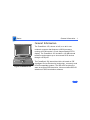
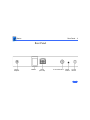
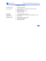
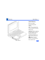
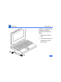
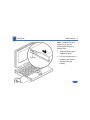
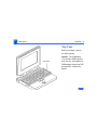
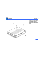
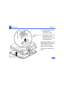
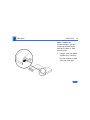
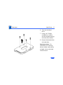
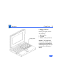
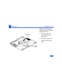
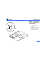
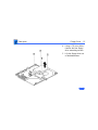
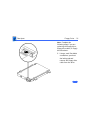
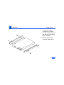
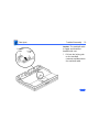
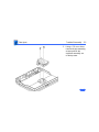
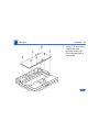
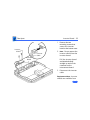
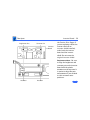
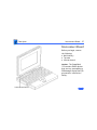
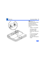
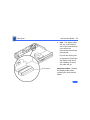
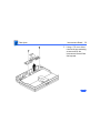
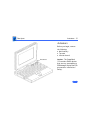
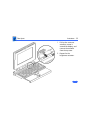
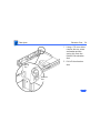
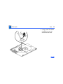
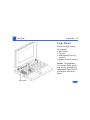
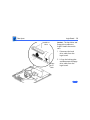
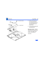
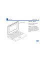
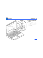
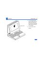
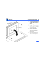
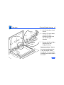
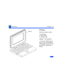
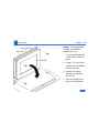
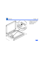
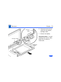
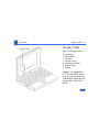
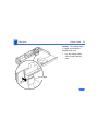
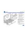
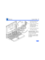
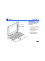
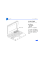
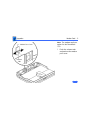
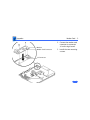
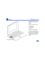
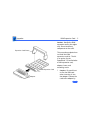
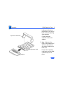
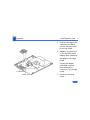
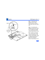
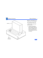
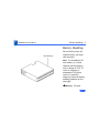
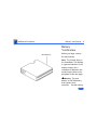
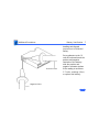
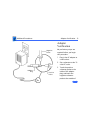
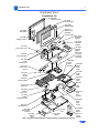
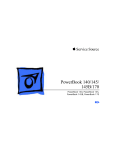
K Service Source
PowerBook 150
K Service Source
Basics
PowerBook 150
Basics
General Information - 1
General Information
The PowerBook 150, shown at left, is an all-in-one
notebook computer that features a 68030 processor
running at 33 MHz and a 9.5 inch diagonal backlit FSTN
display. The PowerBook 150 includes a 120 MB internal
hard drive and supports up to six external SCSI devices
through a SCSI port.
Figure: PowerBook 150
The PowerBook 150 internal hard drive is based on IDE
(Intelligent Device Electronics) technology, commonly used
in DOS-compatible systems. The IDE drive functions the
same as a typical SCSI hard drive; it does not affect SCSI ID
selections or SCSI termination schemes.
Basics
Rear Panel - 2
Rear Panel
Power
Adapter
Modem
SCSI
(HDI-30)
Printer/Modem
Reset
Button
Power
Button
K Service Source
Specifications
PowerBook 150
Specifications
Introduction - 1
Introduction
You can also find specifications information for this product in the
Spec Database, which you can access in one of three ways:
Ñ Launch it directly by double-clicking the Apple Spec Database
runtime alias at the top level of the Main Service Source CD.
Ñ Select "Apple Spec Database" from the Service Source dropdown main menu.
Ñ Click the Acrobat toolbar icon for the database, which is near
the right end of the toolbar with the letters "SP."
Specifications
Processor - 2
Processor
CPU
Motorola 68030 microprocessor
33 MHz
Addressing
32-bit internal registers
32-bit address bus
32-bit data bus
Specifications
Memory - 3
Memory
RAM
4 MB, expandable to 40 MB
ROM
1 MB
PRAM
256 bytes of parameter memory
VRAM
256K of static video display memory
Clock/Calendar
CMOS custom chip
Specifications
Disk Storage - 4
Disk Storage
Floppy Drive
19 mm high, 1.4 MB Apple SuperDrive
Hard Drive
2.5 in., 120 MB IDE hard drive
Specifications
I/O Interfaces - 5
I/O Interfaces
SCSI
HDI-30 SCSI port with 1.5 MB/sec. transfer rate
Supports up to six external SCSI devices
Connect SCSI device to computer with HDI-30 SCSI system cable
Serial
One RS-422 serial port; mini DIN-8 connector
Specifications
I/O Devices - 6
I/O Devices
Keyboard
Built-in standard Apple keyboard
63 keys domestic; 64 keys ISO
18 mm vertical pitch; 18.63 mm horizontal pitch
Two-level tilt adjustment
Trackball
30 mm diameter, dual button
Apple Desktop Bus (ADB) interface
Specifications
Sound and Video - 7
Sound and Video
Video Display
9.5 in. diagonal screen
Flat-panel, film-compensated supertwist nematic (FSTN) liquid
crystal display
640 lines by 480 pixels
Sound Generator
Apple sound chip provides 8-bit sound capable of driving stereo
headphones or other stereo equipment through the sound jack
Specifications
Electrical - 8
Electrical
Main Battery
Nickel cadmium (NiCad) battery
Provides 2Ð4 hours of usage before recharging
Power Adapter
110Ð240 VAC line voltage
50Ð60 Hz
US, Japanese, United Kingdom, Australian, and European versions
Specifications
Physical - 9
Physical
Dimensions
Height: 2.3 in. (5.8 cm)
Width: 11.3 in. (28.7 cm)
Depth: 9.3 in. (23.6 cm)
Weight
5.5 lb. (2.5 kg) with battery
Specifications
Environmental - 10
Environmental
Operating
Temperature
50Ð95¡ F (10Ð35¡ C)
Storage
Temperature
14Ð140¡ F (-10 to 60¡ C)
Relative Humidity
20Ð80% noncondensing
Operating Altitude
0Ð10,000 ft. (0Ð3048 m)
Shipping Altitude
0Ð15,000 ft. (0Ð4722 m)
K Service Source
Troubleshooting
PowerBook 150
Troubleshooting
General/ - 1
General
The Symptom Charts included in this chapter will help you
diagnose specific symptoms related to your product. Because cures
are listed on the charts in the order of most likely solution, try
the first cure first. Verify whether or not the product continues to
exhibit the symptom. If the symptom persists, try the next cure.
(Note: If you have replaced a module, reinstall the original module
before you proceed to the next cure.)
If you are not sure what the problem is, or if the Symptom Charts
do not resolve the problem, refer to the Flowchart for the product
family.
For additional assistance, contact Apple Technical Support.
Troubleshooting
Power Manager Reset/ - 2
Power Manager Reset
Reset the power manager if
• The battery and power adapter are proven good, but the
computer will not power on.
• The computer will not reset after a system crash.
To reset the power manager in a PowerBook 150,
• Remove the AC adapter and the battery.
• Using a paper clip, hold down the reset button on the back of the
computer for 5–10 seconds.
• Reconnect the AC adapter and briefly push the reset button
again. You should hear a small pop from the speaker.
• Turn on the computer.
• If the computer powers on, reinstall the battery. If the
computer does not start, it may need servicing.
Troubleshooting
Symptom Charts/Startup - 3
Symptom Charts
Startup
RAM failure occurs
(eight-tone error
chord sequence
sounds after startup
chord)
1
2
Replace RAM expansion card.
Replace logic board.
Hardware failure
occurs (four-tone
error chord sequence
sounds after startup
chord)
1
Disconnect hard drive data cable and reboot system. If
startup sequence is normal, replace hard drive.
Disconnect floppy drive cable and reboot system. If startup
sequence is normal, replace floppy drive.
Replace logic board.
2
3
Troubleshooting
Symptom Charts/Startup (Continued) - 4
Startup (Continued)
Screen displays
checkerboard pattern;
no startup chime
1
2
3
Reseat RAM expansion card.
Replace RAM expansion card.
Reseat display cable.
Troubleshooting
Symptom Charts/Power - 5
Power
Screen is blank;
computer doesn’t
respond
1
2
3
4
5
6
7
8
Press reset switch.
Connect power adapter and reboot computer in 3–4 minutes.
Try known–good, charged main battery.
Check all interconnect board and logic board connections.
Reset the power manager.
Replace keyboard.
Replace interconnect board.
Replace logic board.
After removing main
battery, some
Control Panel
settings are different
1
2
Replace interconnect board.
Replace logic board.
Troubleshooting
Symptom Charts/Power (Continued) - 6
Power (Continued)
Power adapter is
plugged in, but
battery DA does not
indicate charger is
connected
1
2
3
4
Check battery charger connection.
Try known-good, charged main battery.
Try known-good power adapter.
Replace logic board.
Low-power warning
appears
1
2
3
Recharge battery or attach power adapter.
Verify that peripherals are low-power.
Reduce use of power-consuming devices or connect power
adapter.
Try known-good, charged main battery.
Try known-good power adapter.
Replace logic board.
4
5
6
Troubleshooting
Symptom Charts/Power (Continued) - 7
Power (Continued)
Computer runs when
plugged in to wall
outlet but not on
battery power;
battery voltage is
within tolerance
1
2
3
4
Reseat battery to make sure battery is mating with contacts
on logic board.
Replace fuse on logic board.
Replace logic board.
Return computer to Apple.
Troubleshooting
Symptom Charts/Video - 8
Video
Row or partial row of
pixels never comes
on or is always on
1
2
3
Thin white line is
always on at middle of
screen
Thin white line is normal for FSTN screens.
Replace display cable.
Replace display.
Replace interconnect board.
Troubleshooting
Symptom Charts/Video (Continued) - 9
Video (Continued)
Display is very light
or totally white
1
2
3
4
5
6
7
8
Adjust screen contrast.
Adjust screen brightness.
Check display cable, inverter board, interconnect board, and
logic board connections.
Replace inverter board.
Replace interconnect board.
Replace display cable.
Replace display.
Replace logic board.
Troubleshooting
Symptom Charts/Video (Continued) - 10
Video (Continued)
No display, but
computer appears to
operate correctly
1
2
Rainbow colors
visible from extreme
viewing angles
Such colors are normal for FSTN screens.
3
4
5
6
7
8
Adjust screen contrast.
Check display cable, inverter board, interconnect board, and
logic board connections.
Replace inverter board.
Replace interconnect board.
Replace power cable.
Replace display cable.
Replace display.
Replace logic board.
Troubleshooting
Symptom Charts/Video (Continued) - 11
Video (Continued)
Image is not uniform
Irregularity in images is normal for FSTN screens. Adjust
contrast and brightness to diminish effect.
Display stopped
working or dimmed
but is fine now
If temperature is under 5 or over 40 degrees centigrade, this
reaction is normal for FSTN screens.
Backlight doesn’t
operate
1
2
3
4
5
6
7
Check cables.
Check display cable, inverter board, interconnect board, and
logic board connections.
Replace inverter board.
Replace inverter cable.
Replace interconnect board.
Replace display.
Replace logic board.
Troubleshooting
Symptom Charts/Video (Continued) - 12
Video (Continued)
Screen goes blank
1
2
Press any key to wake computer from system sleep.
Check display cable connection.
Pixel is always white
or always black
Replace display.
Troubleshooting
Symptom Charts/Floppy Drive - 13
Floppy Drive
Audio and video
present, but internal
drive does not operate
1
2
3
4
5
Try known-good floppy disk.
Check floppy drive cable connection.
Replace floppy drive cable.
Replace floppy drive.
Replace logic board.
Disk ejects while
booting; display
shows Mac icon with
blinking X
1
2
3
4
5
6
Try known-good system disk.
Verify that trackball or mouse button is not stuck.
Check floppy drive cable connection.
Replace floppy drive cable.
Replace floppy drive.
Replace logic board.
Troubleshooting
Symptom Charts/Floppy Drive (Continued) - 14
Floppy Drive (Continued)
Disk does not eject
Disk initialization
fails
1
2
3
4
5
6
Switch off system and hold mouse button down while you
switch system on.
Insert opened paper clip into hole beside drive.
Check floppy drive cable connection.
Replace floppy drive cable.
Replace floppy drive.
Replace logic board.
1
2
3
4
5
Try known-good floppy disk.
Install inverter shield.
Check floppy drive cable connection.
Replace floppy drive cable.
Replace floppy drive.
Troubleshooting
Symptom Charts/Floppy Drive (Continued) - 15
Floppy Drive (Continued)
Read/write/copy
error
1
2
3
4
5
Try known-good floppy disk.
Install inverter shield.
Check floppy drive cable connection.
Replace floppy drive cable.
Replace floppy drive.
Troubleshooting
Symptom Charts/Hard Drive - 16
Hard Drive
Internal hard drive
does not operate
1
2
3
4
5
Make sure power adapter is connected.
Check hard drive cable connection.
Replace hard drive cable.
Replace hard drive.
Replace logic board.
Troubleshooting
Symptom Charts/Peripherals - 17
Peripherals
After connecting
external SCSI device,
computer doesn’t boot
1
2
3
5
6
7
Switch on external SCSI device before starting computer.
Check cable connections.
Verify that standard Apple terminator terminates end of SCSI
chain.
Verify that SCSI select switch setting on external device is
unique.
Verify operation of internal hard drive.
Try known-good external SCSI device.
Replace logic board.
1
2
3
4
Press reset switch.
Check interconnect board and logic board connections.
Replace interconnect board.
Replace logic board.
4
Cursor does not move
when using trackball
Troubleshooting
Symptom Charts/Peripherals (Continued) - 18
Peripherals (Continued)
Cursor intermittently
does not move or
moves erratically
1
2
3
4
5
Clean ball and rollers of trackball.
Replace trackball.
Replace keyboard.
Replace interconnect board.
Replace logic board.
Cursor moves, but
clicking trackball
button has no effect
1
2
3
4
5
Check interconnect board and logic board connections.
Replace trackball.
Replace keyboard.
Replace interconnect board.
Replace logic board.
Troubleshooting
Symptom Charts/Peripherals (Continued) - 19
Peripherals (Continued)
No response to any
key on keyboard
1
2
3
4
5
Reset power manager.
Check connections of keyboard to interconnect board.
Replace keyboard.
Replace interconnect board.
Replace logic board.
Known-good
ImageWriter,
ImageWriter II, or
LQ does not print
1
2
3
4
5
6
Verify that System is current.
Verify that Chooser and Control Panel settings are correct.
Check cables.
Replace printer interface cable.
Try known-good printer.
Replace logic board.
Troubleshooting
Symptom Charts/Peripherals (Continued) - 20
Peripherals (Continued)
Known-good
LaserWriter does not
print
Device connected to
external modem port
doesn’t work
1
2
3
4
5
6
Verify that System is current.
Verify that Chooser and Control Panel settings are correct.
Check cables.
Replace printer interface cable.
Try known-good printer. If printer works, troubleshoot
network. Refer to Networking and Communications manual.
Replace logic board.
1
2
3
4
5
6
Verify that External Modem is selected in CDEV.
Verify that System is current.
Verify third-party setup software.
Check cables.
Attach device to known-good computer.
Replace logic board.
Troubleshooting
Symptom Charts/Peripherals (Continued) - 21
Peripherals (Continued)
I/O devices are
unrecognized or
garbage is
transmitted or
received
1
2
3
4
5
6
Verify that System is current.
Check cables.
Verify that SCSI device has standard Apple terminator.
Verify that SCSI select switch setting on external device is
unique.
Attach device to known-good computer.
Replace logic board.
Troubleshooting
Symptom Charts/Internal Modem - 22
Internal Modem
Internal modem
options do not appear
in CDEV
1
2
3
4
Remove and reseat modem card.
Verify that System is current.
Replace modem card.
Replace logic board.
Modem does not
respond properly to
AT command set
instructions
1
Verify that baud rate and data format settings of
communications application are compatible with internal
modem and remote modem.
Check phone cord connection and operation.
Remove and reseat modem card.
Verify that System is current.
Replace modem card.
2
3
4
5
Troubleshooting
Symptom Charts/Internal Modem (Continued) - 23
Internal Modem (Continued)
Strange mix of
characters appears
on screen
1
2
3
4
5
6
Verify that baud rate and data format settings of
communications application are compatible with internal
modem and remote modem.
Check phone cord connection and operation.
Remove and reseat modem card.
Verify that System is current.
Replace modem card.
Replace logic board.
Modem interferes
with system sound
1
2
3
4
Remove and reseat modem card.
Replace modem card.
Replace interconnect board.
Replace logic board.
Troubleshooting
Symptom Charts/Internal Modem (Continued) - 24
Internal Modem (Continued)
Modem does not
respond to incoming
call
1
2
3
4
If computer is in sleep mode, verify that Wake On Ring
option in CDEV is selected.
Check phone cord connection and operation.
Replace modem card.
Replace logic board.
Modem has no sound
output
1
2
3
4
Verify that Control Panel volume setting is above 0.
Replace modem card.
Replace interconnect board.
Replace logic board.
Modem connects but
does not communicate
with remote modem
1
Verify that remote modem needs error correction (error
correction is internal modem default).
If remote modem does not need error correction, type AT
&Q0 to disable error correction.
2
Troubleshooting
Symptom Charts/Miscellaneous - 25
Miscellaneous
Screen goes blank and
computer shuts down
every few minutes
Adjust sleep delays in Control Panel or connect power adapter.
Application seems to
run slower after few
seconds
Connect power adapter.
Hard drive is slow to
respond, or screen
goes blank too often
Adjust sleep delays in Control Panel or connect power adapter.
Troubleshooting
Symptom Charts/Miscellaneous (Continued) - 26
Miscellaneous (Continued)
No sound from
speaker
1
2
3
4
Verify that volume setting in Control Panel is 1 or above.
Check connection of interconnect board to logic board.
Replace interconnect board.
Replace logic board.
K Service Source
Take Apart
PowerBook 150
Take Apart
Main Battery - 1
Main Battery
Before you begin,
disconnect the power
adapter.
Note: This procedure also
covers removal of the main
battery door.
Important: Before removing
the main battery, use the
Macintosh Shut Down
command. Otherwise, all
RAM contents will be lost.
Warning: The main
battery is a NiCad battery
that contains toxic
±
Main Battery
Take Apart
Main Battery - 2
materials. Review battery
handling and disposal
instructions in Bulletins/
Safety.
1
2
Slide open the battery
door.
Using the battery door as
a handle, pull out the
main battery.
Take Apart
Main Battery - 3
Note: Complete the next
steps only if you are
replacing the battery or
battery door.
3
End Tab
4
Slide the battery door
completely open.
Pull the end tab until it
releases, and remove
the door from the
battery.
Take Apart
Top Case - 4
Top Case
Before you begin, remove
the main battery.
Top Case
Caution: The PowerBook
150 contains CMOS devices
that are very susceptible to
ESD damage. Review the ESD
precautions in Bulletins/
Safety.
Take Apart
Top Case - 5
1
Using a T-8 torx driver,
remove the five torx
screws from the bottom
case.
Take Apart
Top Case - 6
2
Interconnect
Cable
3
Lift up the top case and
disconnect the
interconnect cable.
Lift off the top case and
unhook the two tab
fasteners from the front
of the bottom case.
Replacement Caution: When
connecting the interconnect
cable, fold the cable as
shown. If it is not folded
correctly, the cable could
short.
Tab Fastener
Take Apart
Hard Drive - 7
Hard Drive
Before you begin, remove
the following:
• Main battery
• Top case
Caution: The PowerBook
150 contains CMOS devices
that are very susceptible to
ESD damage. Review the ESD
precautions in Bulletins/
Safety.
Hard Drive
Take Apart
Hard Drive - 8
Caution: The hard drive
cable is fragile. Handle it
with care.
1
Disconnect the hard
drive cable from the
logic board.
Take Apart
Hard Drive - 9
2
3
4
Hard Drive
Cable
Carefully fold back the
hard drive cable.
Using a T-8 torx driver,
remove the three hard
drive mounting screws.
Lift the hard drive out of
the bottom case.
Take Apart
Hard Drive - 10
Note: Complete the
following steps if you are
replacing the hard drive,
hard drive cable, or hard
drive bracket.
5
Using a small flat-blade
screwdriver, carefully
pry the hard drive cable
from the hard drive.
Take Apart
Hard Drive - 11
6
7
8
Turn over the hard
drive.
Using a #1 Phillips
screwdriver, remove
the four screws securing
the hard drive bracket.
Remove the bracket from
the hard drive.
Replacement Note: For
information on returning
drives, cables, and carriers
to Apple, refer to the Hard
Drives manual.
Take Apart
Floppy Drive - 12
Floppy Drive
Floppy Drive
Before you begin, remove
the following:
• Main battery
• Top case
• Modem card (if present)
Caution: The PowerBook
150 contains CMOS devices
that are very susceptible to
ESD damage. Review the ESD
precautions in Bulletins/
Safety.
Take Apart
Floppy Drive - 13
Caution: The hard drive
cable is fragile and should be
handled with care.
1
Floppy Drive
2
Hard Drive
Cable
Disconnect the hard
drive cable from the
logic board.
Carefully fold back the
cable from the floppy
drive.
Take Apart
Floppy Drive - 14
Caution: The floppy drive
cable is fragile and should be
handled with care.
3
Locking
Tab
Lift the locking tab on
the floppy drive
connector and disconnect
the floppy drive cable
from the logic board.
Take Apart
Floppy Drive - 15
4
5
Using a T-8 torx driver,
remove the four floppy
drive mounting screws.
Lift the floppy drive out
of the bottom case.
Take Apart
Floppy Drive - 16
Note: Complete the
following steps if you are
replacing the floppy drive,
floppy drive cable, or floppy
drive brackets.
6
Using a small flat-blade
screwdriver, push out
the locking tab and
remove the floppy drive
cable from the drive.
Take Apart
Floppy Drive - 17
7
8
Using a #0 Phillips
screwdriver, remove
the four screws securing
the left and right floppy
drive brackets.
Remove the brackets
from the floppy drive.
Take Apart
Trackball Assembly - 18
Trackball
Assembly
Trackball
Assembly
Before you begin, remove
the following:
• Main battery
• Top case
Caution: The PowerBook
150 contains CMOS devices
that are very susceptible to
ESD damage. Review the ESD
precautions in Bulletins/
Safety.
Take Apart
Trackball
Cable
Trackball Assembly - 19
Locking
Tab
Caution: The trackball cable
is fragile and should be
handled with care.
1
Pull out the locking tab
on the trackball
connector and disconnect
the trackball cable.
Take Apart
Trackball Assembly - 20
2
Using a T-8 torx driver,
remove the two mounting
screws and lift the
trackball assembly out
of the top case.
Take Apart
Keyboard - 21
Keyboard
Keyboard
Before you begin, remove
the following:
• Main battery
• Top case
• Trackball assembly
Caution: The PowerBook
150 contains CMOS devices
that are very susceptible to
ESD damage. Review the ESD
precautions in Bulletins/
Safety.
Take Apart
Keyboard - 22
Caution: The keyboard
ribbon cables are fragile and
should be handled with care.
1
Keyboard
Cables
Lift up the locking tabs
on the two keyboard
connectors and
disconnect the keyboard
cables.
Take Apart
Keyboard - 23
2
Using a T-8 torx driver,
remove the seven
mounting screws and
lift the keyboard out of
the top case.
Take Apart
Inverter Board - 24
Inverter Board
Before you begin, remove
the following:
• Main battery
• Top case
Inverter Board
Caution: The PowerBook
150 contains CMOS devices
that are very susceptible to
ESD damage. Review the ESD
precautions in Bulletins/
Safety.
Take Apart
Inverter Board - 25
1
Inverter
Shield
Inverter
Board
Inverter
Cable
2
3
Remove the two
mounting screws that
secure the inverter
board to the bottom case.
Note: Do not remove the
inverter shield from the
inverter board.
Pull the inverter board
and attached shield
straight up and off the
connector on the
interconnect board.
Disconnect the inverter
cable.
Replacement Note: Inverter
shields are available from
Take Apart
Brightness Pot
Inverter Board - 26
Contrast Pot
Inverter
Board
Actuator
Actuator
the Service Price Pages. If
you are replacing a defective
inverter that has an
inverter shield installed,
order both the inverter
board and the inverter
shield. Do not reuse the
original inverter shield.
Replacement Note: Be sure
to align the brightness and
contrast pots on the inverter
board with the plastic
actuators on the top case. It
is easiest to align the pots
and actuators if you set both
to their extreme outer
positions.
Take Apart
Interconnect Board - 27
Interconnect Board
Before you begin, remove
the following:
• Main battery
• Top case
• Inverter board
Caution: The PowerBook
150 contains CMOS devices
that are very susceptible to
ESD damage. Review the ESD
precautions in Bulletins/
Safety.
Interconnect Board
Take Apart
Interconnect Board - 28
The
interconnect board contains
hazardous materials.
Return bad interconnect
boards to Apple for proper
disposal.
±Warning:
1
Caution: The keyboard
and display ribbon
cables are fragile.
Handle these cables with
care.
Lift up the locking tabs
on the two keyboard
connectors and
disconnect the keyboard
cables.
Take Apart
Interconnect Board - 29
2
Note: The display cable
will not come entirely
out of the connector until
you remove the
interconnect board from
the top case.
Pull out the locking tab
on connector J2 and ease
the display cable out of
the connector as far as
the cable will go.
J2 Connector
Replacement Note: Connect
the display cable before
replacing the interconnect
board.
Take Apart
Interconnect Board - 30
3
Using a T-8 torx driver,
remove the two mounting
screws and lift the
interconnect board from
the top case.
Take Apart
Actuators - 31
Actuators
Before you begin, remove
the following:
• Main battery
• Top case
• Inverter board
Actuators
Caution: The PowerBook
150 contains CMOS devices
that are very susceptible to
ESD damage. Review the ESD
precautions in Bulletins/
Safety.
Take Apart
Actuators - 32
1
2
Pull up the contrast
actuator, rotate it
toward the display, and
remove the actuator
from the top case.
Repeat for the
brightness actuator.
Take Apart
Elevation Feet - 33
Elevation Feet
Before you begin, remove
the following:
• Main battery
• Top case
Elevation Foot
Elevation Foot
Caution: The PowerBook
150 contains CMOS devices
that are very susceptible to
ESD damage. Review the ESD
precautions in Bulletins/
Safety.
Take Apart
Elevation Feet - 34
1
2
Spring
Clip
Elevation
Foot
Using a T-8 torx driver,
remove the torx screw
and washer and the
spring clip from the
inside of the elevation
foot.
Pull off the elevation
foot.
Take Apart
Fuse - 35
Fuse
Before you begin, remove
the following:
• Main battery
• Top case
Caution: The PowerBook
150 contains CMOS devices
that are very susceptible to
ESD damage. Review the ESD
precautions in Bulletins/
Safety.
Fuse
Take Apart
Fuse - 36
1
Using a small flat-blade
screwdriver, pry up
and remove the fuse.
Take Apart
Logic Board - 37
Logic Board
Before you begin, remove
the following:
• Main battery
• Top case
• RAM expansion card (if
present)
• Modem board (if present)
Caution: The PowerBook
150 contains CMOS devices
that are very susceptible to
ESD damage. Review the ESD
precautions in Bulletins/
Safety.
Logic Board
Take Apart
Logic Board - 38
Caution: The hard drive and
floppy drive cables are
fragile. Handle them with
care.
Hard Drive
Cable
1
2
Floppy
Drive
Cable
Disconnect the hard
drive cable from the
logic board.
Lift up the locking tabs
and disconnect the floppy
drive cable from the
logic board.
Take Apart
Torx
Screw
Tall
Hex
Nut
Logic Board - 39
Hex Nut Screw
Logic Board
3
4
Remove the three hex
nut screws and three
torx screws that secure
the logic board to the
bottom case.
Lift the logic board out of
the bottom case.
Replacement Note: Replace
the tall hex nut screw in the
corner of the logic board
nearest the RAM card
connector.
Take Apart
Display Bezel - 40
Display Bezel
Display Bezel
Before you begin, remove
the main battery.
Caution: The PowerBook
150 contains CMOS devices
that are very susceptible to
ESD damage. Review the ESD
precautions in Bulletins/
Safety.
Take Apart
Display Bezel - 41
1
Screw
Plastic Plugs
Plastic
Plug
2
Remove the two plastic
plugs.
Using a T-8 torx driver,
remove the two bezel
mounting screws from
the display.
Take Apart
Display Bezel - 42
3
Display Bezel
4
Pull the display bezel
down and away from the
display and release the
bezel from the mounting
tabs at the top and sides
of the display.
Lift the bezel off the
display.
Take Apart
Clutches/Display Housing - 43
Clutches/Display
Housing
Before you begin, remove
the following:
• Main battery
• Display bezel
Clutch Assembly
Caution: The PowerBook
150 contains CMOS devices
that are very susceptible to
ESD damage. Review the ESD
precautions in Bulletins/
Safety.
Take Apart
Clutches/Display Housing - 44
1
Display Housing
EMI Shield
2
Display
3
4
Cover the keyboard with
a clean cloth or sheet of
paper.
Using a T-8 torx driver,
remove the four display
mounting screws.
Remove the display
from the housing and
EMI shield.
Place the display facedown on the keyboard.
Take Apart
Clutches/Display Housing - 45
Inverter
Cable
5
6
Clutch Covers
Right
Clutch
7
Pull off the three clutch
covers.
Using a T-8 torx driver,
remove the three
mounting screws from
the left and right
clutches.
Remove the left and right
clutches from the
display housing.
Replacement Note: Replace
the short mounting screws
in the top-inside clutch
threadings. The top-outside
threadings are used to mount
the bezel.
Take Apart
Clutches/Display Housing - 46
Display Housing
EMI Shield
Replacement Note: To avoid
pinching the inverter cable,
make sure it routes as
illustrated.
8
Remove the display
housing and EMI shield
from the case.
Take Apart
Display - 47
Display
Display
Before you begin, remove
the following:
• Main battery
• Display bezel
Caution: The PowerBook
150 contains CMOS devices
that are very susceptible to
ESD damage. Review the ESD
precautions in Bulletins/
Safety.
Take Apart
Display - 48
Caution: The display cable
is fragile and should be
handled with care.
Display Housing
EMI Shield
1
Display
2
3
4
Cover the keyboard with
a clean cloth or sheet of
paper.
Using a T-8 torx driver,
remove the four display
mounting screws.
Remove the display
from the housing and
EMI shield.
Place the display facedown on the keyboard.
Take Apart
Display - 49
5
Locking
Tab
Using a small flat-blade
screwdriver, pry up
and disconnect the
display cable.
Take Apart
Display - 50
6
Inverter
Cable
7
Disconnect the inverter
cable from the display
backlight cable.
Remove the display.
Replacement Note: To avoid
pinching the inverter cable,
make sure it routes as
illustrated.
Inverter Cable
Right
Clutch
Backlight
Cable
Take Apart
Display Cable
Display Cable - 51
Display Cable
Before you begin, remove
the following:
• Main battery
• Top case
• Inverter board
• Interconnect board
• Display bezel
• Display
Caution: The PowerBook
150 contains CMOS devices
that are very susceptible to
ESD damage. Review the ESD
precautions in Bulletins/
Safety.
Take Apart
Display Cable - 52
Caution: The display cable
is fragile and should be
handled with care.
1
Ferrite Bead
Pry the display cable
ferrite bead from the
case.
Take Apart
Display Cable - 53
2
Left
Clutch
Cover
3
Center
Clutch
Cover
Left Clutch
4
Pull off the center and
left clutch covers.
Using a T-8 torx driver,
remove the three
mounting screws from
the left clutch.
Remove the clutch from
the display housing.
Replacement Note: Replace
the short mounting screw in
the top-inside clutch
threading. The top-outside
threading is used to mount
the bezel.
Display
Cable
5
Remove the display cable
from the case.
Take Apart
Inverter Cable - 54
Display Housing
Inverter Cable
Inverter Cable
Before you begin, remove
the following:
• Main battery
• Top case
• Inverter board
• Display bezel
Caution: The PowerBook
150 contains CMOS devices
that are very susceptible to
ESD damage. Review the ESD
precautions in Bulletins/
Safety.
Take Apart
Center
Clutch
Cover
Right
Clutch
Cover
Inverter Cable - 55
Inverter
Cable
1
2
3
Right
Clutch
Pull off the center and
right clutch covers.
Using a T-8 torx driver,
remove the three
mounting screws from
the right clutch.
Remove the clutch from
the display housing.
Replacement Note: Replace
the short mounting screw in
the top-inside clutch
threading. The top-outside
threading is used to mount
the bezel.
Take Apart
Inverter Cable - 56
Backlight Cable
Inverter Cable
Replacement Note: To avoid
pinching the inverter cable,
make sure it routes as
illustrated.
4
5
Fold back the right edge
of the display EMI shield
and disconnect the
inverter cable from the
backlight cable.
Remove the inverter
cable from the case.
K Service Source
Upgrades
PowerBook 150
Upgrades
Modem Card - 1
Modem Card
Before you begin, remove
the following:
• Main battery
• Top case
Modem Card
Caution: The PowerBook
150 contains CMOS devices
that are very susceptible to
ESD damage. Review the ESD
precautions in Bulletins/
Safety.
Upgrades
Modem Port Cover
Modem Card - 2
Note: The modem card is an
option for the PowerBook
150.
1
Release
Tabs
Pinch the release tabs
and push out the modem
port cover.
Upgrades
Modem Card - 3
2
Modem
Modem Card Connector
J4 Connector
3
Connect the modem card
connector to connector
J4 on the logic board.
Install the two mounting
screws.
Upgrades
RAM Expansion Card - 4
RAM Expansion
Card
Before you begin, remove
the following:
• Main battery
• Top case
Caution: The PowerBook
150 contains CMOS devices
that are very susceptible to
ESD damage. Review the ESD
precautions in Bulletins/
Safety.
RAM Expansion Card
Upgrades
RAM Expansion Card - 5
Caution: Handle the RAM
expansion card by the edges
only. Do not touch any
components on the card.
Expansion Card Brace
RAM Expansion Card
Adapter
This procedure explains how
to install the RAM
expansion card kit. The kit
is an option for the
PowerBook 150 and includes
a RAM expansion card,
adapter, brace, and
mounting screw.
1
Caution: Be careful not
to flex the RAM card
when inserting it into
the adapter. Connect the
card to the adapter by
Upgrades
RAM Expansion Card - 6
holding onto the white
projections on the top of
both cards and squeezing
them together.
Expansion Card Brace
2
RAM Expansion Card
Adapter
Connect the RAM
expansion card to the
adapter.
Note: Make sure the
ridge on the underside of
the brace fits between
the rows of chips on the
RAM card.
Position the expansion
card brace over the RAM
card and snap it into
place.
Upgrades
RAM Expansion Card - 7
3
4
J7 Connector
Brace Slot
5
Insert the two legs of the
expansion card brace
into the two brace slots
in the logic board.
Caution: Be careful not
to flex the RAM card or
adapter when connecting
the adapter to the logic
board.
Connect the adapter
(with RAM card and
brace attached) to
connector J7 on the logic
board.
Install the mounting
screw.
Upgrades
Adapter
Logic Board
Take-Apart
Tool
RAM Expansion Card - 8
Note: To disconnect the
adapter from the logic
board, be sure to use the
Apple logic board take-apart
tool.
Note: To verify that the
upgrade is successful, check
the Total Memory message
(for systems with virtual
memory switched off) or the
Built-in Memory message
(for systems with virtual
memory switched on). The
memory size should be 4 MB
of soldered RAM plus the
RAM on the expansion
board. If the memory size is
Upgrades
RAM Expansion Card - 9
incorrect, replace the RAM
expansion card. If the
memory size is still
incorrect, send the
computer to Apple.
K Service Source
Additional Procedures
PowerBook 150
Additional Procedures
Battery Recharger - 1
Battery Recharger
No preliminary steps are
required before you begin
this procedure.
Battery
1
LED
Battery
Recharger
Using the PowerBook
power adapter, plug the
battery recharger into a
power outlet and insert
the main battery into the
recharger.
Additional Procedures
Battery Recharger - 2
2
Track the status of the
battery. If the LED is
• Yellow, the battery is
charging.
• Green, the battery is
ready to use.
• Off, the charger is
unplugged, the
battery is bad, the
power adapter is
defective, or the
charger is defective.
Additional Procedures
Battery Handling - 3
Battery Handling
Main Battery
No preliminary steps are
required before you begin
this procedure.
Note: The PowerBook150
main battery is a nickel
cadmium (NiCad) battery
with a voltage of 5.65-7.5
volts. Its longevity is
estimated at 500 power
cycles. To extend its
longevity, follow the battery
handling guidelines on the
next page.
±Warning:
The main
Additional Procedures
Battery Handling - 4
battery contains toxic
materials. Review battery
handling and disposal
instructions in Bulletins/
Safety.
The following are guidelines
for properly handling the
NiCad battery:
• Handle the battery
carefully. Do not drop,
puncture, disassemble,
mutilate, or incinerate
the battery.
• Fully charge a
replacement battery
before using it; Apple
Additional Procedures
Battery Handling - 5
•
•
•
•
•
ships batteries in a
partially-charged state.
Do not leave the battery
in the computer for
longer than two weeks
without plugging in the
power adaptor.
Completely discharge and
recharge the battery once
a month.
Store the battery in the
protective battery case.
Do not short-circuit the
battery terminals.
Keep the battery in a
cool, dark place.
Additional Procedures
Battery Verification - 6
Battery
Verification
Main Battery
Before you begin, remove
the main battery.
Note: The Control Strip on
the PowerBook 150 desktop
is a general indicator of the
battery charge. Use a
voltmeter to determine the
actual charge. Refer to the
procedure on the next page.
The main
battery is a NiCad battery
that contains toxic
materials. Review battery
±Warning:
Additional Procedures
Battery Verification - 7
handling and disposal
instructions in Bulletins/
Safety.
Positive Probe
Negative Probe
Set a voltmeter to the 10
volts DC scale and touch the
positive and negative
terminals of the battery
with the positive and
negative voltmeter probes.
If the reading is not above
5.7 volts, recharge (first)
or replace the battery.
Additional Procedures
Adapter Verification - 8
Adapter
Verification
Negative
Probe
No preliminary steps are
required before you begin
this procedure.
1
2
Adapter
Plug
3
Positive
Probe
Plug in the AC adapter to
a wall socket.
Set a voltmeter to the 10
volts DC scale.
Touch the positive
voltmeter probe to the
inside of the adapter
plug, and touch the
negative voltmeter
probe to the outside of
Additional Procedures
Adapter Verification - 9
the adapter plug. If the
reading is not 7.5–7.9
volts, replace the
adapter.
K Service Source
Exploded View
PowerBook 150
Exploded View
1
Exploded View
PowerBook 150
922-0986
Display Housing
661-0143
FSTN Display
922-0988
Display Bezel
922-0987
EMI Shield
875-0112
Rubber Plug
922-0984
Inverter Cable
922-0983
Display Cables
815-1248
Brightness
Actuator
076-0468
Elevation
Foot Kit
815-1231
End Clutch Cover
076-0567
External
Battery
Recharger
661-1515
Trackball
Assembly
699-0497
Clutch Assembly
815-1230
Center
Clutch Cover
661-0190
Interconnect
Board
922-0992
Floppy
Drive
Bracket
922-1120
Inverter
Board
805-0397
Inverter Shield
661-0712
Keyboard
815-0578
Modem
Port Cover
661-1659
DRAM
Expansion Card
661-0140
Motherboard
922-0985
815-1236
Motherboard
Foot
Insulator
661-0013
815-1240
Battery
Battery
Door
This is a generic representation of a product family. Configurations may vary.
922-0982
Floppy
Drive
Cable
661-0061
Floppy
Drive
922-0991
Floppy
Drive
Bracket
Hard
Drive
922-1123
Hard
Drive
Bracket
922-0981
Hard
Drive
Cable
922-0990
Case
Bottom
922-1117
Power
Adapter