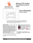
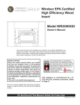
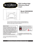
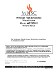
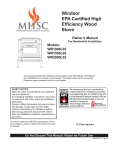
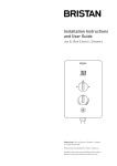
1
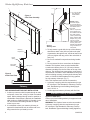
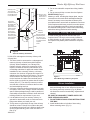
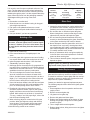
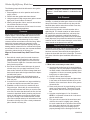
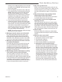
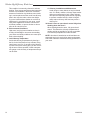
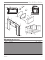
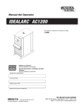
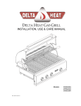
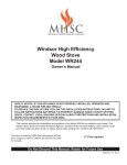
Windsor EPA Certified
High Efficiency Wood
Insert
Model WR2500X02
Owner’s Manual
This manual describes the installation and operation of the Model WR2500X02 noncatalytic wood heater. This heater meets US Environmental Protection Agency emission
limits for wood heaters. Under specific conditions this heater has been shown to
5129
deliver
heat at rates ranging from 9,500 to 57,800 BTU/hr.
WR2500X02 cover
Safety notice
Read this entire manual before you install
and use your fireplace insert. If not properly
installed, a house fire may result. To reduce
the risk of fire, follow the installation instructions. Failure to follow instructions may result in property damage, bodily injury or even
death. Contact local building, fire officials or
authorities having jurisdiction about permits,
restrictions and installation inspection requirements in your area.
This unit is not mobile home approved.
This appliance is manufactured for a 6”
(152 mm) Dia. chimney connection. (Refer
to Page 7)
This stove is listed by OMNI-Test Laboratories of Portland, Oregon to meet UL1482 for the US and ULC-S628
for Canada.
Do Not Discard This Manual: Retain for Future Use
30005129 3/10 Rev. 1
Windsor High Efficiency Wood Insert
CAUTION
After reading these instructions, if you have any doubt
about your ability to complete your installation in a
professional like manner you should obtain the services
of an installer versed in all aspects as to the correct
and safe installation. Do not use temporary makeshift
compromises during installation.
About Your Appliance
1. Hot while in operation. Keep children, clothing and
furniture away. Contact may cause skin burns.
2. Do not burn garbage or flammable fluids.
3. Check with the building inspector’s office for compliance with local codes; a permit may be required.
4. This appliance requires installation in a masonry
type fireplace only. DO NOT INSTALL IN A FACTORY BUILT FIREPLACE SUCH AS A ZERO CLEARANCE.
5. Always connect this unit to a chimney and NEVER
vent to another room or inside a building.
6. Do not connect to any air distribution duct or system.
7. Do not connect this unit to a chimney flue serving
another appliance.
8. A stainless steel chimney liner may be required.
Check with local building, fire officials or authorities
having jurisdiction in your area.
9. Do not use chemicals or fluids to start the fire.
10. The connector pipe and chimney should be inspected periodically and cleaned if necessary.
11. Remember the clearance distances when you place
furniture or other objects within the area. DO NOT
store wood, flammable liquids or other combustible
materials too close to the unit.
12. Contact your local municipal or provincial fire
authority for information on how to handle a chimney fire. Have a clearly understood plan to handle
a chimney fire. In the event of a chimney fire, turn
air control to closed position and CALL THE FIRE
DEPARTMENT.
13. DO NOT tamper with air control beyond normal
adjustment.
14. Once the required draw is obtained, operate only
with doors closed and open door slowly when refueling. (This will reduce or eliminate smoke from
entering the room). These units are not mobile
home approved. Do not install this unit in a mobile
home or trailer.
Why the correct chimney size is important
Your appliance operates best using a minimum 6” (152
mm) diameter chimney. The maximum chimney diameter must not exceed 10” (254 mm) in diameter or have
a cross sectional area greater than 85 in2 (550 cm2).
Today’s solid fuel appliances are much more efficient
than in the past. The units are designed to give you
controlled combustion, as well as maximum heat
transfer, using less fuel to do so. The result of better
heat transfer is lower chimney temperatures, making
the chimney size important for good draft. Poor draft
will create poor performance of your appliance, and a
safety hazard.
Should you experience a problem with smoke entering the room or poor combustion, call in a local
chimney expert.
Burn Rate
With the door closed, the rate of burning is regulated by
the amount of air allowed to enter the unit through the
air control. With experience you will be able to set the
control for the desired heat and burning time.
Attempts to achieve higher output rates that exceed
heater design specifications can result in permanent
damage to the heater. The recommended wood load
is level with the top of the firebricks. Overloading may
prevent sufficient air entering the heater to properly fuel
the fire.
DO NOT tamper with air control beyond the normal
adjustment capacity.
WARNING: Operate this heater only with the door
closed.
ALWAYS PROVIDE A SOURCE OF FRESH AIR
INTO THE ROOM WHERE THE UNIT IS INSTALLED.
FAILURE TO DO SO MAY RESULT IN AIR STARVATION OF OTHER FUEL BURNING APPLIANCES
AND THE POSSIBLE DEVELOPMENT OF HAZARDOUS CONDITIONS.
THIS HEATER IS EXTREMELY HOT WHILE IN OPERATION.
SERIOUS BURNS CAN RESULT FROM CONTACT.
KEEP CHILDREN, CLOTHING AND FURNITURE
AWAY.
Proposition 65 Warning: Fuels used in gas, woodburning or oil fired appliances, and the products of
combustion of such fuels, contain chemicals known
to the State of California to cause cancer, birth defects and other reproductive harm.
California Health & Safety Code Sec. 25249.6
30005129
Windsor High Efficiency Wood Insert
Specifications
Model WR2500X02 non-catalytic wood heater. This heater meets US Environmental Protection Agency’s emission
limits for wood heaters. Under specific conditions this heater has been shown to deliver heat at rates ranging from
9,500 to 58,000 BTU per hour.
Model WR2500X02 is listed by OMNI-Test Laboratories of Portland, OR and meets UL 1482 for the US and ULC S
627-00 for Canada.
266M” (679 mm) 206M” (527 mm) * 956M” (235 mm) 216M” (553 mm) 1656M” (413 mm) 31” (787 mm) 8(6” (225 mm) 44” (1118 mm) 10” (254 mm) 16” (406 mm) * Adjustable 10” (254 mm) to 14” (356 mm) Figure 1
WR2500X02 Dimensions
5129
NOTE: Refer to Pages 4 and 5 for clearancesWR2500X02 dims
and floor
protection information.
30005129
Windsor High Efficiency Wood Insert
Installation
Clearance to Combustible Constructions
1. Remove all boxes of firebricks and any packaging
from inside the appliance.
2. Clean out the masonry fireplace ensuring the ashes
are placed in a metal container.
3. Remove or lock open the damper plate in the masonry fireplace.
4. Contact local building, fire officials or authorities
having jurisdiction about permits, restrictions and
installation inspection requirements in your area.
5. The insert must be installed in compliance with the
minimum clearances to combustible constructions
and floor protection stated on appliance certifications label (located on back of unit) and listed below.
Refer to Page 5 for further instructions about floor
protection.
FAILURE TO FOLLOW THESE MINIMUM CLEARANCES REQUIREMENTS MAY RESULT IN AN UNSAFE INSTALLATION.
6. Install the refractory bricks. (Fig. 3)
7. Install faceplate onto insert. (Page 7) The trim
should fit against the face of the fireplace. If this is
not a good fit, a 2” (51 mm) wide strip of fiberglass
insulation can be used to insure a good fit.
12”
(305 mm)
Max
Mantel
Top Trim
D
B
Side Trim
Side Wall
Face Plate
C
E
Floor
Floor Protector
A
F
ST1022
Figure 2
Clearance to Combustibles
Clearance to Combustible Constructions
ST1022
A
Unit to
Side Wall
12” (305 mm)
DW2500 clearances
B
Unit to
Top
Trim
10” (254 mm)
10/08
C
Unit to Side Trim
10” (254 mm)
D
Unit to Mantel
17” (430 mm)
E
Floor Protector Front
16” (405 mm) in the US
18” (457 mm) in Canada
F
Floor Protector Side
8” (203 mm)
Refer to Page 6 for Floor Protection requirements
30005129
Windsor High Efficiency Wood Insert
6
6
2
5
4
6
6
2
*
1
1
*
1
5
1
1
*
1
1
1
*
ST1031
t
Fr o n
3
3
1
2
Figure 3
Install Firebrick
Tip - Install Front (*) Fire Bricks First
Floor Protection
This appliance must be installed in a masonry fireplace
ST1031
enclosure built in accordance
install firebrick
with local building codes. DO
10/08
NOT INSTALL IN A FACTORY
BUILT FIREPLACE SUCH AS A
ZERO CLEARANCE.
Floor protector must extend to
cover area shown on the diagram
below.
When the floor covering the area
shown is concrete, no floor protector is required.
Carpeting and any other combustible material shall not cover the
floor protector.
ST1023
Face
Plate
8” (203 mm)
Figure 4
Floor Protector
If a combustible surface is applied to the concrete floor,
a clearance must be maintained equivalent to the area
reserved for the floor protector. (Fig. 4)
If the area shown is a combustible floor or a combustible floor covering, a 3/8” (10 mm) thick noncombustible
millboard floor protector or durable equivalent must be
installed. The pad must cover the area shown.
A grouted ceramic floor tile surface installed per local
building code is considered a durable equivalent.
Door Side of
Appliance
16” (406 mm) in the US
18” (457 mm) in Canada
8” (203 mm)
Floor Protector
Faceplate Assembly
Refer to Figure 5
34
1. Assemble top (#1) to sides (#2) using #8 x 1/2” Tek
FLOORPROTECTION
screws (#9).
2. Attach the side right and left trims (#5,6) to sides
(#2) using #8 brass screws.
3. Attach top right and left trims (#3,4) together with the
articulating angles (#8).
4. Install corner brackets (#7) to top trim.
5. Attach top trim to face plate placing corner brackets
into side trim and tightening screws in the corner
brackets to secure.
Face Plate Installation
1. Hook one end of spring (#10) into hole on stove top.
2. Hook the other end of the spring through the 1/8” (3
mm) hole in the faceplate top. (Fig. 6)
3. Slide the face plate against the masonry wall. NOTE:
Use the installation bulletin supplied with the face
plate as protection to prevent scratching the stove
top.
30005129
Windsor High Efficiency Wood Insert
7
6” (152 mm) Min.
Dia. Stainless
Steel Flexible
Liner
3
Figure 5
Face Plate Assembly
4
9
8
5
7
1
9
6
2
2
ST1026
Figure 7
Chimney Liner
Masonry
Fireplace
9
ST1024
End of
Spring
ST1024
faceplate assy
10/08
Face Plate
Assembly
Spring #10
Figure 6
Install Face Plate
ST1025
Chimney
34
CONTACT YOUR LOCAL
BUILDING AUTHORITY
FACEPLATEINSTALL
FOR APPROVED METHODS
OF INSTALLATION.
1. A chimney connector shall not pass through an attic,
roof space, closet, floor, ceiling or similar concealed
space. Where passage through a wall or partition of
combustible constructions is desired, the installation
shall conform to CAN/CSA B365 (in Canada). In the
US, check with local building officials for requirements in your area.
2. It is advisable to have your masonry chimney inspected for deterioration such as cracks and crumbling mortar before you install your unit.
NOTES: A stainless steel adapter
is recommended for
fastening the stainless
steel flexible liner to
the collar.
Male or crimped end
of the adapter must
be installed inside the
flue collar. Drill flue
collar to permanently
fasten stainless steel
adapter using a minimum of 3 screws.
Fasten stainless steel
chimney liner to the
stainless steel adapter
using manufactures
instructions.
3. To help 34
ensure a good draft, the top of the chimney
should be
at least 3 feet (914 mm) above the point
CHIMNEYLINER
of penetration
through the roof, and be at least 2 feet
(610 mm) higher than any point of the roof within 10
feet (3 m).
4. Do not use makeshift compromises during installation.
5. Do not remove bricks or mortar from the fireplace.
Canada: This fireplace insert must be installed with
a continuous chimney liner of 6” (152 mm) minimum
diameter extending form the flue collar to the top of the
chimney. The chimney liner must conform to the class 3
requirements of CAN/ULC-S635 Standard for lining systems for existing masonry or factory-built chimneys and
vents, or CAN/ULC-S640 Standard for lining systems
for new masonry chimneys. (Fig. 7)
USA: This fireplace insert must be connected to:
1. A chimney complying with the requirements for type
HT chimneys in the Standard for Chimneys, Factorybuilt, Residential type and building Heating Appliance, UL103, or
2. A code-approved masonry chimney with flue liner.
Alternate Chimney Installation
Applies to USA ONLY
Contact your local building authority for approved methods of installation.
WARNING: This fireplace insert must be connected to:
A chimney complying with the requirements for type
HT chimneys in the Standard for Chimneys, Factorybuilt, Residential Type and building Heating Appliance,
30005129
Windsor High Efficiency Wood Insert
Chimney Liner
The cross-sectional area must not
exceed 85 square
inches (550 cm2)
Chimney Connector into the
first section of
the flue liner
The smoke
chamber must
be sealed using
noncombustible material, to
prevent smoke
from re-entering the room.
The installation
must allow the
chimney system
to be inspected
and cleaned.
Masonry
Fireplace
Drill flue collar to
permanently fasten chimney connector. A minimum
of 3 screws will be
required.
Insert
5. Do not use makeshift compromises during installation.
6. Do not remove bricks or mortar from the fireplace.
EXCEPTION (5) Page 7:
Masonry or steel, including the damper plate, may be
removed from the smoke shelf and adjacent damper
frame if necessary to accommodate a chimney liner,
provided that their removal will not weaken the structure
of the fireplace and chimney, and will not reduce protection for combustible materials to less than required by
the National Building Code. Consult with local building
authorities having jurisdiction before starting.
IMPORTANT: Warning Label Installation
A metal warning tag has been included with your
fireplace insert. This tag is to be securely installed in
a visible location on your fireplace so that it is known
the fireplace has possibly been modified to accept the
insert.
ST1027
Figure 8
Alternate Chimney Installation
UL103 OR A code-approved
masonry chimney with
34
chimney liner. 53CHIMNEYLINER
1. This insert must
be connected to a code-approved
masonry chimney or listed factory-built fireplace
chimney. When installation is to a factory-built
fireplace chimney, a direct flue connection will be
required. Contact the chimney manufacturer or local building authorities for approved method. When
installation is into a masonry chimney, a chimney
connector of a minimum 24 gauge steel must be installed into the first chimney liner section. The cross
sectional area of the either type of chimney must
not be less than the inside cross sectional area of
the flue collar, nor shall it be greater than 85 square
inches (550 cm2). The chimney connector must be
secured with a minimum 3 screws at the flue collar
and each adjoining sections.
2. A chimney connector shall not pass through an attic,
roof space, closet, floor, ceiling or similar concealed
space. Where passage through a wall or partition of
combustible construction is desired, check with local
building officials for requirements in your area.
3. It is advisable to have your masonry chimney inspected for deterioration such as cracks and crumbling mortar before you install your unit.
4. To help ensure a good draft, the top of the chimney
should be at least 3 feet (914 mm) above the point
of penetration through the roof, and be at least 2 feet
(619 m) higher than any point of the roof within 10
feet (3 m).
30005129
Metal Tag
ST1028
Figure 9
Place Metal Tag on Masonry Fireplace
34
METALTAG
Blower Installation
1. Remove screws from insert body, route cord under
body and through the cut out. Attach the blower with
the screws previously removed. (Fig. 10) Blower
unit should be removed occasionally, inspected and
cleaned.
BE SURE TO DISCONNECT POWER SUPPLY BEFORE SERVICING BLOWER.
2. DO NOT REMOVE INSULATING MATERIAL FROM
FIRE BOX.
3. Install handle holder on left side of insert using
blower mounting screw. (Fig. 11)
Windsor High Efficiency Wood Insert
Operation
Do not use a grate or elevate fire. Build wood fire
directly on hearth. When the stove is used for the first
time the solvents in the paint will smoke off.
Face Plate
Wood
This heater is designed to burn natural wood only. Higher efficiency and lower emissions generally result when
burning air dried seasoned hardwood, as compared to
softwood or to green or freshly cut hardwood.
Insert
O
PE
N
ST1029
CL
O
SE
Air Control
spring Handle
3-Prong
Grounded Plug
use 110V A, 15
Amp Supply Power
Handle
Holder
Blower Assembly
Fan Mounting
Screw (2)
Figure 1034
Blower Installation
BLOWERINSTALL
Handle
ST1030
Blower Mounting
Screw
Figure 11
Install Handle Holder
Handle Holder
Only use dry seasoned wood. Green wood, besides
burning at only 60 percent of the fuel value of dry wood,
deposits creosote on the inside of your stove and along
the chimney. This can cause an extreme danger of
chimney fire. To be called “seasoned”, wood must be
dried for a year. Regardless of whether the wood is
green or seasoned, it should be stored in a well-sheltered, ventilated area to allow proper drying during the
year to come. Wood should be stored beyond recommended clearance from combustibles.
DO NOT BURN:
Treated Wood
Solvents
Trash
Coal
Garbage
Cardboard Colored Paper
Instructions for First Burn - Curing the Stove Paint
Your stove has been painted with the highest quality
stove paint and has special break-in procedures. The
heat generated by the normal operation of the stove,
will serve to harden the paint.
Ventilate the house during the first three times the stove
is used. The paint on the stove will give off smoke,
carbon dioxide and an odor. Without adequate ventilation, concentrations of smoke could irritate you or cause
damage to person and/or property. Open doors and
windows and use a fan if necessary. After the initial
burns the paint will be cured and there should be no
more smoke.
Each of the initial burns should be conducted as follows:
1. The first and second burns should be approximately
250° F (120° C) for approximately 20 minutes.
2. The third burn should be between 500° F (260 to
370° C) for at least 45 minutes. The important fact is
the paint should be cured slowly. Avoid hot fires during the curing process.
During the curing process the paint will be gummy.
Once cured the paint will remain hard.
34
HANDLEHOLDER
30005129
Windsor High Efficiency Wood Insert
It is normal to see flat spots on painted surfaces of the
stove. The flat spots on the paint surface indicate the
hotter surfaces of the stove, and is caused by the heat
radiating through the paint. It is also expected that shiny
spots caused by friction from the packaging materials,
will disappear during the curing of the stove.
SO:
1. Remember to ventilate well.
2. Allow the stove to cure before burning for long periods at high temperatures.
3. Flat spots on the painted surfaces are normal.
4. Shiny spots on the paint surface before burning is
normal.
5. Call your dealer if you have any questions.
Building a Fire
Never use gasoline, gasoline-type lantern fuel,
kerosene, charcoal lighter fluid or similar liquids
to start or ‘freshen up’ a fire in this heater. Keep
all such liquids well away from the heater while it
is in use.
1. Open inlet air control fully.
2. Place a small amount of crumpled paper in the
stove.
3. Cover the paper with a generous amount of kindling
in a teepee fashion and a few small pieces of wood.
4. Ignite the paper and close door. If fire dies down
substantially, open door slightly.
5. Add larger pieces of wood as the fire progresses being careful not to overload. Do not fill firebox beyond
firebrick area. An ideal coal bed of 1” to 2” should be
established to achieve optimum performance.
6. This unit is designed to function most effectively
when air is allowed to circulate to all areas of the
firebox. An ideal means of achieving this is to rake a
slight (1” to 2” wide) trough in the center of the coal
bed from front to back prior to loading the fuel.
7. Once fuel has been loaded, close the door and open
air inlet control fully until fire is well established (approx. 10 minutes) being careful not to overfire.
8. Readjust air inlet control to desired burn rate. If
excessive smoke fills firebox, open air inlet control
slightly until flames resume and wood is sufficiently
ignited. While a basic rule of thumb is “closed-low”,
“1/2 way - medium” and “fully open-high”, refer to the
Inlet Air Control Settings chart.
9. When refueling, adjust air control to the fully open
position. When fire brightens, slowly and carefully
open the door. This procedure will prevent gases
from igniting causing smoke and flame spillage.
10.Add fuel being careful not to overload.
30005129
Desired Burn Setting
Low
Med / High
High
Inlet Air Control Settings
Inlet **Approx.
Air Setting
BTU Output
Fully Closed
9,500
1/2” (13 mm) Open
16,315
Fully Open
58,000
Glass Care
The following use and safety tips should be observed.
1. Inspect the glass regularly for cracks and breaks. If
you detect a crack or break, extinguish the fire immediately and contact your dealer for replacement.
2. Do not slam door or otherwise impact the glass.
When closing doors, make sure that logs or other
objects do not protrude and impact the glass.
3. Do not clean the glass with materials which may
scratch (or otherwise damage) the glass. Scratches
on the glass can develop into cracks or breaks.
4. Never attempt to clean the glass while unit is hot. If
the deposit is not very heavy, normal glass cleaners are adequate with a plain, nonabrasive scouring
pad. Heavier deposits may be removed with the use
of a readily available oven cleaner.
5. Never put substances which can ignite explosively
in the unit since even small explosions in confined
areas can blow out the glass.
6. This unit has an airwash system, designed to reduce
deposits on glass.
Replace glass only with high temperature Robax
Pyroceram of the proper size and thickness.
Gasket Replacement
After extensive use, the sealing material which provides
glass and door seal may need to be replaced if it fails
to sustain its resilience. Inspect glass and door seal periodically to ensure for proper seal. If gaskets become
frayed or worn, replace immediately.
Contact your dealer for approved replacement parts.
The following steps should be followed for glass gasket
replacement:
1. Ensure appliance is not in operation and has thoroughly cooled.
2. Remove screw and glass clip.
3. Lift glass out from glass clip.
4. Remove old gasket and clean glass.
5. Replace new gasket starting at the bottom of glass
working along edges, being sure to center gasket
channel on glass.
6. Trim to length and butt ends together.
7. Replace glass in door, being sure not to over-tighten
screw and clip.
Windsor High Efficiency Wood Insert
The following steps should be followed for door gasket
replacement:
1. Ensure appliance is not in operation and has thoroughly cooled.
2. Remove old door gasket and clean channel.
3. Using an approved high temperature gasket cement,
apply a thin coat in bottom of channel.
4. Starting at hinge side of door, work into around door
unit, and butt and trim to length.
5. Close door and allow three to four hours for cement
to set before restarting appliance.
Creosote
When wood is burned slowly, it produces tar and other
organic vapors. These combine with moisture to form
creosote. Creosote vapors condense in the relatively
cool chimney flue of a slow-burning fire. As a result,
creosote residue accumulates on the flue lining. When
ignited, this creosote makes an extremely hot fire.
The chimney should be inspected regularly during the
heating season to determine if a creosote build-up has
accumulated. If this is the case, the creosote should be
removed to reduce the risk of chimney fire.
Ways to Prevent and Keep Unit Free of Creosote
1. Burn with air control open for several minutes at
numerous intervals throughout the day during the
heating season, being careful not to over-fire unit.
This removes the slight film of creosote accumulated
during low burn periods.
2. Burn stove with draft control wide open for several
minutes every time you apply fresh wood. This allows wood to achieve the charcoal stage faster and
burns wood vapors which might otherwise be deposited within the system.
3. Burn only seasoned wood. Avoid burning wet or
green wood. Seasoned wood has been dried for at
least one year.
4. A small hot fire is preferable to a large smouldering
one that can deposit creosote within the system.
5. Establish a routine for the fuel, wood burner and
firing technique. Check daily for creosote build-up
until experience shows how often you need to clean
to be safe. Be aware that the hotter the fire, the less
creosote is deposited. Weekly cleaning may be necessary in mild weather even though monthly cleaning may be enough in the coldest months. Contact
your local municipal authority for information on how
to handle a chimney fire. Have a clearly understood
plan to handle a chimney fire.
10
WARNING: Things to remember in case of chimney fire: 1. Close draft control. 2. Call the fire department.
Ash Disposal
During constant use, ashes should be removed every
few days, or whenever ashes get to three to four inches
deep in the firebox. Remove ashes only when the fire
has died down and the ashes have cooled. Even then,
expect to find a few hot embers.
Ashes should be placed in a metal container with a
tight-fitting lid. The closed container of ashes should
be placed on a noncombustible floor, well away from
all combustible materials, pending final disposal. If
the ashes are disposed of by burial in soil or otherwise
locally dispersed, they should be retained in the closed
container until all cinders have thoroughly cooled. Other
waste should not be placed in the ash can.
Inspection of the Insert
Inspection of the insert can be accomplished with the
removal of the face plate only. Once the face plate
has been removed, there should be enough space to
inspect the insert with the aid of a flash light. To remove
face plate, follow face plate installation instructions on
Page 7.
IMPORTANT
Helpful Hints
1. What is the correct way to start a fire?
a. You will need small pieces of dry wood (kindling)
and paper. Use only newspaper or paper that has
not been coated or had unknown materials glued
or applied to it. Never use coated (typically advertising flyers) or colored paper.
b. Open the door of the wood stove.
c. Crumple several pieces of paper and place them
in the center of the firebox and directly on to the
firebricks of the wood stove. Never use a grate to
elevate the fire.
d. Place small pieces of dry wood kindling) over the
paper in a teepee manner. This allows for good
air circulation, which is critical for good combustion.
e. Light the crumpled paper in 2 or 3 locations:
NOTE: It is important to heat the air in the stovepipe for draft to start.
f. Fully open the air control of the wood stove and
close the door until it is slightly open, allowing
for much needed air to be introduced into the fire
box. Never leave the door fully open as sparks
from the kindling may occur causing injury or
property damage. As the fire begins to burn the
30005129
Windsor High Efficiency Wood Insert
kindling, some additional kindling may be needed
to sustain the fire. DO NOT add more paper after
the fire has started.
g. Once the kindling has started to burn, add some
of the smaller pieces of seasoned (dry) firewood.
NOTE: Adding large pieces at the early stages
will only serve to smother the fire. Continue
adding small pieces of seasoned (dry) firewood,
keeping the door slightly open until each piece
starts to ignite. Remember to always open the
door slowly when placing wood into the fire.
h. Once the wood has started to ignite and the
smoke has reduced, close the wood stove door
fully. The reduction of smoke is a good indication
that the draft in the chimney has started and good
combustion is now possible. Larger pieces of
seasoned (dry) firewood can now be added when
there is sufficient space in the firebox. Adjust the
air control setting to desired setting.
i. NOTE: The lower the air control setting the longer
the burn time of your firewood.
2. What type of wood is best to use as firewood?
Dry seasoned hardwood should be used. Avoid
green unseasoned wood. Green wood, besides
burning at only 60 percent of the fuel value of dry
seasoned wood, will deposit creosote on the inside
of your stove and along the inside of your chimney.
3. What does dry seasoned wood mean, and what
is considered hardwood?
Wood that has been dried for a period of one year
in a well-ventilated and sheltered area would be
considered dry seasoned wood. Hardwoods are
generally from slow growth trees (Example: Oak and
fir) Softwoods are generally from fast growth trees.
(Example: Pine and spruce).
4. Will following the above listed steps for starting
a fire result in perfect results all the time?
The quick answer is most of the time. There are
many variables that may affect your success rate
when starting a fire. Most of those variables and how
to deal with them will be learned through experience.
Your ability to start a good fire will significantly increase with time and patience. Some of the reasons
for poor stove performance will be covered next.
30005129
5. Why can’t I get the fire lit?
Damp or wet wood and poor draft are the main reasons for poor results in starting a fire. Always use dry
seasoned wood for your fire. Even wood dried for
two years will be difficult to ignite, if it has become
wet.
6. Why is there always a large quantity of thick
black smoke present in the firebox?
A large quantity of thick black smoke in the firebox,
is a good indication that the draft is poor.
7. Is it normal for soot to cover the glass at the
beginning of a fire?
Your stove has been built with an air wash system
that will help keep the glass clear when the firebox
has reached a good operating temperature and has
a good draft. Cold firebox temperature and poor draft
cause sooting of the glass. Once the firebox temperature and the draft increases, the soot will burn off.
8. What is draft?
Draft is the ability of the chimney to exhaust draw
by-products produced during the normal combustion
process.
9. What can cause a poor draft?
The most common factors for poor draft are:
a. Atmospheric pressure and air supply
b. Environmental conditions
c. Cold chimney temperature
d. Poor chimney installation and maintenance
a. Atmospheric Pressure and Air Supply
Atmospheric pressure affecting the draft from a
chimney can be either outside the home, inside
the home or both. Outside the home, a high-pressure day (clear and cool) generally creates a better draft in the chimney than a low-pressure day
(overcast and damp). Inside the home, normal
household appliances, such as clothes dryers
and forced air furnaces compete for air resulting
in inadequate amounts of air available to fuel a
fire and create a condition known as negative
pressure. Under extreme conditions of negative pressure the combustion by-products can
be drawn from the chimney and into the house.
11
Windsor High Efficiency Wood Insert
This condition is commonly referred to as down
drafting. There are several factors that impact the
amount of air available in the home. Increased
amounts of insulation vinyl windows, extra caulking in various places and door seals can all keep
heat in but may also make a home too airtight.
If you are in doubt about whether or not there is
sufficient air in your home for your stove, curtail
using those appliances known to consume the
air where possible, or open a window or door to
allow air to enter the home.
b. Environmental Conditions
High trees, low lying house location such as in
a valley, tall buildings or structures surrounding
your house and windy conditions can cause poor
draft or down drafting.
c. Cold Chimney Temperature
Avoid cold chimney temperatures by burning a
hot fire for the first fifteen to forty minutes, being
careful not to over fire. If any part of the chimney
or parts of the stove start to glow, you are over firing the stove. Where possible, install a temperature gauge on the chimney so temperature drops
can be seen.
12
d. Chimney Installation and Maintenance
Avoid using too many elbows or long horizontal
runs. If in doubt, contact a chimney expert and/or
chimney manufacturer for help. Clean chimney,
rain caps and especially spark arrester regularly,
to prevent creosote build up, which will significantly reduce chimney draw and may cause a
chimney fire.
10.Should I close or open the air control fully when
shutting down the stove?
When shutting down the stove, fully open the air
control. This allows the chimney temperatures to
remain as high as possible for as long as possible.
Cold chimney temperatures create creosote.
NOTE: this sheet is intended as an aid and does not
supersede any local, provincial or state requirements.
Check with officials or authorities having jurisdiction in
your area.
30005129
Windsor High Efficiency Wood Insert
15 8
1
6
7
13
5 16
9
10 17
14
30 34 2 3 26 11 35 31 28 27 33 12 4 34 30 24 23 31 25 29 25 19 22 23 21 23 18 23 18 19 22 18 18 18 18 18 18 32 20 MHSC reserves the right to make changes in design, materials, specifications, prices and discontinue colors and products at any time, without
notice.
5129
WR2500x2 parts
WR2500X02 Wood Insert
Item No.
1.
2.
3.
4.
5.
6.
7.
8.
9.
10.
11.
12.
13.
14.
30005129
Description
Door Casting - Black
Glass and Gasket
1/8” (3 mm) Glass Gasket
5/8” (16 mm) Door Gasket
Pawl Assembly
Handle - Black, Wood
Insert Lifter Handle - Nickel
Screw - 1/4-20 x 3 Handle Assembly
Lock Nut
Glass Clips
Screw #10 x 1/2
Hinge Pin
3/8 Retaining Ring
Qty.
1
1
4.6’
5.2’
1
1
1
1
1
1
7
7
2
2
Part No.
S12071
S31141
S15001
S15011
30002362
1600664
1600650
1201310
5004245
1203290
S37034
S11086
S11005
S11090
13
Windsor High Efficiency Wood Insert
WR2500X02 Wood Insert (continued)
14
Item No.
15.
16.
17.
18.
19.
20.
21.
22.
23.
24.
25.
26.
27.
28.
29.
30.
31.
32.
33.
34.
35.
Description
Baffle Assembly
Secondary Air Tube
Cotter Pin
Firebrick 4M\zn” (113 mm) x 9” (229 mm) x 1Z\v” (32 mm)
Firebrick 4M\zn” (113 mm) x 7Z\v” 184 mm) x 1Z\v” (32 mm)
Firebrick 4M\zn” (113 mm) x 4Z\x” (114 mm) x 1Z\v” (32 mm)
Firebrick 2Z\v” (57 mm) x 8” (203 mm) x 1Z\v” (32 mm)
Firebrick - Angled
Firebrick 4M\zn” (113 mm) x 8” (203 mm) x 1Z\v” (32 mm)
Faceplate - Top
Faceplate - Side
Trim - Top Right
Trim - Top Left
Trim - Side Right
Trim - Side Left
Corner - 90°
#8 Screw
Spring
Articulated Angle
Back plate, Trim Corner
Back plate, Articulated Angle
Qty.
1
3
3
9
2
1
1
2
4
1
2
1
1
1
1
2
6
2
1
2
2
Part No.
S41467
S32711
S11421
S16040
S16043
S16046
S16271
S16013
S16138
S38050
S38051
90000072
90000071
90000076
90000075
S11092
50960
S11403
S11127
30004606
30004607
30005129
Limited Lifetime Warranty
Windsor High Efficiency Wood Insert
Limited Three Year Warranty
MHSC (hereafter referred to as the “company”) warrants that
your new Windsor brand wood burning plate steel stove or masonry wood insert is free from manufacturing and material defects for a period of three years from the date of sale, subject to
the following conditions and limitations.
Limited One Year Warranty
Electrical components such as blowers and speed controls are
covered for one year only. Glass door panels are covered for
thermal breakage only. To clean glass, use a ceramic glass
cleaner or polish. Do not use ammonia-based cleaners. A suitable cleaner is available from your nearest Hearth Products dealer. DO NOT CLEAN GLASS WHILE HOT AND DO NOT USE
ABRASIVE CLEANERS.
Excluded from Warranty
Brass parts should be cleaned with soap and warm water and
immediately dried. Brass parts may also be damaged by external
chemicals. Gold and any other plated parts will not be covered
under this warranty. Plated surfaces should be cleaned by using
denatured alcohol only and rubbed lightly with a lint-free nonabrasive cloth. Excessive rubbing or polishing may remove the
plated finish. Discoloration of certain parts is normal and is not a
defect, and therefore not covered under warranty.
This warranty will not include or extend to paint, gaskets, baffles or firebrick components, and does not cover any removable
firebox components such as brick retainers or stainless steel air
tubes.
Extended Limited Lifetime Warranty
The company offers a limited lifetime warranty on the firebox
(welds only), castings and ash drawers on any of Windsor wood
burning products. The limited lifetime warranty is extended to the
original owner only, and is subject to proof of purchase by the
original owner and residential use.
1. The new Windsor product must be installed and operated at all
times in accordance with the installation and operation instructions supplied with the appliance, and installation must be to local
and national codes. Any alterations, willful abuse, accident, over
firing or misuse will not be covered under warranty. NOTE: Some
minor movement of certain parts is normal and is not a defect
and therefore, not covered under warranty.
2. The warranty is non-transferable, and is made to the original
owner, provided that the purchase was made through an authorized MHSC supplier. The serial number must be supplied along
with the Bill of Sale, showing the date of purchase, at the time the
claim is submitted.
3. This warranty is limited to the repair or replacement of parts
only and is applicable only to those parts found to be defective
in material or construction that have been subjected to normal
conditions of use and service. All defects must be confirmed by
the company or an authorized representative. If requested by the
company, defective parts must be shipped back transportation
prepaid, to the company. Credits will be issued upon receipt of
return of the defective product to the company.
4. The company, at its discretion, can fully discharge all obligation
with respect to this warranty by refunding the wholesale price of
the defective part(s).
5. Any installation, labor, construction, transportation or other related costs or expenses arising from defective parts, repair,
replacement or otherwise of same, will not be covered by this
warranty, nor will the company assume responsibility for same.
Further, the company will not be responsible for any incidental,
indirect or consequent damages, except as provided by law, and
in no event shall they exceed the original purchase price.
6. All other warranties - expressed or implied - with respect to the
product, its components and accessories, or any obligations /liabilities on the part of the company are hereby expressly excluded.
7. MHSC neither assumes, nor authorizes any third party to assume, on MHSC’s behalf, any other liabilities with respect to the
sale of this MHSC product.
8. The warranties as outlined within this document do not apply to
chimney components or other products made by other manufacturers when used in conjunction with the installation of this product. Improper use or the use of non-approved components may
nullify your warranty. If in doubt, contact your nearest authorized
MHSC supplier or MHSC Customer Service Department.
9. MHSC will not be responsible for:
• Down drafts or spillage caused by environmental conditions
such as near-by trees, buildings, rooftops, hills, mountains or
ineffective chimney design.
• Inadequate ventilation, excessive offsets or negative air
pressure caused by mechanical systems such as furnaces,
clothes dryers, fans, etc.
10.This warranty is void if:
• The appliance has been operated in atmospheres contaminated by chlorine, fluorine, or other damaging chemicals.
• This appliance has been subjected to prolonged periods of
dampness or condensation.
• The appliance has any damage due to water, or weather
damage that is the result of, but not limited to, improper chimney/venting installation.
• The appliance has been subjected to willful or accidental
abuse or misuse.
• Corrosive driftwood, manufactured logs or other fuels are
used other than as outlined in the installation and operating
instructions.
• The appliance is not maintained in good condition, including
firebrick and gaskets.
IF WARRANTY SERVICE IS REQUIRED
Contact MHSC Customer Service. Make sure you have your
sales receipt and the model/serial number of your MHSC product.
Do not attempt to do any service work yourself, unless pre-approved by MHSC in writing this will void the warranty.
MHSC must authorize service and provide a Warranty Claim
Number prior to any warranty related service calls. Without an
authorization number, any service work will not be deemed warranty.
NOTE: Some states and provinces do not allow the exclusion
or limitation of incidental or consequential damages. The above
limitation may not apply to you.
MHSC
149 Cleveland Drive
Paris, KY 40361
KEEP THIS WARRANTY
Serial # _______________________________
Model # ______________________________
Date Purchased ________________________
30005129
15
MHSC
149 Cleveland Drive • Paris, Kentucky 40361
www.mhsc.com