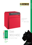
Download REMEHA GAS 360 S Instruction manual
Transcript
Remeha Gas 360 S
English
Gas-fired boilers
20/07/05
Technical
instructions
Contents
Introduction . . . . . . . . . . . . . . . . . . . . . . . . . . . . . . . . . . . . . . . . . . . . . . . . . . . . . . . . . . . . . . . . . . . . . . . . . . . . . . . . .3
1 Regulations . . . . . . . . . . . . . . . . . . . . . . . . . . . . . . . . . . . . . . . . . . . . . . . . . . . . . . . . . . . . . . . . . . . . . . . . . . . . . . . . . . . . . . . . . . . . . .3
2 Symbols used. . . . . . . . . . . . . . . . . . . . . . . . . . . . . . . . . . . . . . . . . . . . . . . . . . . . . . . . . . . . . . . . . . . . . . . . . . . . . . . . . . . . . . . . . . . . .3
Description . . . . . . . . . . . . . . . . . . . . . . . . . . . . . . . . . . . . . . . . . . . . . . . . . . . . . . . . . . . . . . . . . . . . . . . . . . . . . . . . . .4
1
2
3
4
5
6
Introduction. . . . . . . . . . . . . . . . . . . . . . . . . . . . . . . . . . . . . . . . . . . . . . . . . . . . . . . . . . . . . . . . . . . . . . . . . . . . . . . . . . . . . . . . . . . . . . .4
Certifications. . . . . . . . . . . . . . . . . . . . . . . . . . . . . . . . . . . . . . . . . . . . . . . . . . . . . . . . . . . . . . . . . . . . . . . . . . . . . . . . . . . . . . . . . . . . . .4
Main parts. . . . . . . . . . . . . . . . . . . . . . . . . . . . . . . . . . . . . . . . . . . . . . . . . . . . . . . . . . . . . . . . . . . . . . . . . . . . . . . . . . . . . . . . . . . . . . . .5
Technical characteristics . . . . . . . . . . . . . . . . . . . . . . . . . . . . . . . . . . . . . . . . . . . . . . . . . . . . . . . . . . . . . . . . . . . . . . . . . . . . . . . . . . . .7
Identification plate . . . . . . . . . . . . . . . . . . . . . . . . . . . . . . . . . . . . . . . . . . . . . . . . . . . . . . . . . . . . . . . . . . . . . . . . . . . . . . . . . . . . . . . . .8
Main dimensions . . . . . . . . . . . . . . . . . . . . . . . . . . . . . . . . . . . . . . . . . . . . . . . . . . . . . . . . . . . . . . . . . . . . . . . . . . . . . . . . . . . . . . . . . .9
Operation . . . . . . . . . . . . . . . . . . . . . . . . . . . . . . . . . . . . . . . . . . . . . . . . . . . . . . . . . . . . . . . . . . . . . . . . . . . . . . . . . .10
1 Furnace operation equipped with safety box S4565 BF 1161 . . . . . . . . . . . . . . . . . . . . . . . . . . . . . . . . . . . . . . . . . . . . . . . . . . . . . . .10
Adapting to another gas . . . . . . . . . . . . . . . . . . . . . . . . . . . . . . . . . . . . . . . . . . . . . . . . . . . . . . . . . . . . . . . . . . . . . .14
1
2
3
4
5
Changing the burner nozzles . . . . . . . . . . . . . . . . . . . . . . . . . . . . . . . . . . . . . . . . . . . . . . . . . . . . . . . . . . . . . . . . . . . . . . . . . . . . . . . .14
Changing the ignition burner injector . . . . . . . . . . . . . . . . . . . . . . . . . . . . . . . . . . . . . . . . . . . . . . . . . . . . . . . . . . . . . . . . . . . . . . . . . .14
Setting the nozzle pressure . . . . . . . . . . . . . . . . . . . . . . . . . . . . . . . . . . . . . . . . . . . . . . . . . . . . . . . . . . . . . . . . . . . . . . . . . . . . . . . . .15
Setting the start up pressure . . . . . . . . . . . . . . . . . . . . . . . . . . . . . . . . . . . . . . . . . . . . . . . . . . . . . . . . . . . . . . . . . . . . . . . . . . . . . . . .16
Attaching the label . . . . . . . . . . . . . . . . . . . . . . . . . . . . . . . . . . . . . . . . . . . . . . . . . . . . . . . . . . . . . . . . . . . . . . . . . . . . . . . . . . . . . . . .17
Commissionning . . . . . . . . . . . . . . . . . . . . . . . . . . . . . . . . . . . . . . . . . . . . . . . . . . . . . . . . . . . . . . . . . . . . . . . . . . . .18
1 Pressure settings and calibrated nozzle markings . . . . . . . . . . . . . . . . . . . . . . . . . . . . . . . . . . . . . . . . . . . . . . . . . . . . . . . . . . . . . . . .18
2 Final checks before commissioning . . . . . . . . . . . . . . . . . . . . . . . . . . . . . . . . . . . . . . . . . . . . . . . . . . . . . . . . . . . . . . . . . . . . . . . . . . .19
Maintenance . . . . . . . . . . . . . . . . . . . . . . . . . . . . . . . . . . . . . . . . . . . . . . . . . . . . . . . . . . . . . . . . . . . . . . . . . . . . . . . .20
1 Checking and cleaning the main components . . . . . . . . . . . . . . . . . . . . . . . . . . . . . . . . . . . . . . . . . . . . . . . . . . . . . . . . . . . . . . . . . . .20
Incidents and solutions. . . . . . . . . . . . . . . . . . . . . . . . . . . . . . . . . . . . . . . . . . . . . . . . . . . . . . . . . . . . . . . . . . . . . . .22
Spare parts Gas 360 S . . . . . . . . . . . . . . . . . . . . . . . . . . . . . . . . . . . . . . . . . . . . . . . . . . . . . . . . . . . . . . . . . . . . . . . .24
Warranty . . . . . . . . . . . . . . . . . . . . . . . . . . . . . . . . . . . . . . . . . . . . . . . . . . . . . . . . . . . . . . . . . . . . . . . . . . . . . . . . . . .33
Remeha Gas 360 S
20/07/05 - 300005180-001-A
Introduction
This product will be marketed in the following European Union
member states:
GB - HU - ES
Directive 97/23/CE
The boilers and hot water tanks are designed and manufactured in
accordance with the sound engineering practice, as requested in
article 3.3 of the directive 97/23/EC; it is certified by compliance with
the directives 90/396/EC, 92/42/EC, 73/23 EC and 89/336/EC.
Gas and oil boilers with a maximum operating temperature of 110°C
and hot water tanks with a maximum operating pressure of 10 bar
pertain to article 3.3 of the directive, and therefore, cannot be CEmarked to certify compliance with the directive 97/23 EC.
1 Regulations
is in any case imperative to conform to the local
Itregulations
in force.
We would draw your attention to the danger of corrosion in
boilers located in or close to premises in which the atmosphere
may be polluted by chloride or fluoride compounds.
For example: Hairdressing salons, industrial premises
(solvents), refrigeration units.
In this event, we cannot uphold the warranty.
2 Symbols used
3
Caution danger
Risk of injury and damage to equipment. Attention must be paid to the warnings on
safety of persons and equipment
Specific information
Information must be kept in mind to maintain comfort
Z
Reference
Refer to another manual or other pages in this instruction manual
Remeha Gas 360 S
20/07/05 - 300005180-001-A
Description
1 Introduction
Gas 360 S boilers are made of cast iron:
- with atmospheric gas burners
- with electronic ignition via the ignition burner for hot water central
heating
- with a useful output of between 54 and 117 kW
The figure given after Gas 360 S indicates the number of sections
which make up the boiler.
Gas 360 S boilers are delivered with a K control panel. They can be
fitted with an optional RC4 and RC5 control unit (master-slave control
unit options).
They are designed to be connected to a chimney.
2 Certifications
2.1
Introduction
- 89/336/EEC Electromagnetic Compatibility Directive
Reference Standard : EN 50.081.1 ; EN 50.082.1 ; EN 55.014
- 92/42/EEC Efficiency Directive ** 1,
Gas fired condensing boiler
It is CE approved under the following number : 0085AU0115
The boilers are in compliance with the EC directives:
- Royal Decree dated 8th January 2004
- 90/396/EEC Gas Appliance Directive:
Reference Standard : EN 297 ; EN 656
- 73/23/EEC Low Voltage Directive:
Reference Standard : EN 60.335.1
2.2
Category
Gas type
Distribution pressure (mbar)
4
- Type B11 (10 to 14 sections): These models can be fitted with the
optional flue gas anti-overflow thermostat.
User country
User country
- Type B11BS (8 sections): This model is factory-fitted with a flue gas
anti-overflow thermostat.
ES
HU
GB
II2H3P
II2H3P
II2H3P
G20
G31
G20
G31
G20
G31
20
37
25
50
20
37
The boilers leave the factory operating with H natural gas.
Remeha Gas 360 S
20/07/05 - 300005180-001-A
3 Main parts
3.1
Boiler
2
7
8 9 10 11
1
6
3a
3b
4b
8502N169A
4a
5a
5b
1
Control panel
2
Connection for a minimum gas control pressure pressure-sensitive
switch
Natural gas: 12.5 mbar
Propane: 20 mbar
3
Gas valve:
a. Gas valve 1st stage ; Type VK4100C1026
b. Gas valve 2nd stage ; Type VK4105C1066 (Formats: 8-12 sections)
and Type VR4605CB1033 (Formats: 14 sections)
Ignition of the principal burner is done progressively.
4
Flame inspection window
a. Flame inspection window 1st stage
b. Flame inspection window 2nd stage
5
Complete ignition burner
a. Ignition electrode: This ensures ignition burner ignition using a high
voltage spark
b. Ionisation probe: It detects flame presence on the ignition burner by
flame ionisation
6
Safety box: The ignition and burner surveillance sequences are
ensured by the safety box.
Type: Honeywell S 4565 BF 1161
activating the reset button, the warning light goes out
After
and the safety control box restarts after a waiting time of
around 1 minute
7
Burner connector 2nd stage
8
Safety control box and burner connector 1st stage
9
Draught diverter thermostat connector (as standard for 8 section
models and optional for 10 to 14 section models (package RD19))
10 Flue damper connector bridge (only for Gas 360 L)
11 Connection kit, cyclic leak proofing control (cyclic leak proofing
controller option, package RD18)
5
Remeha Gas 360 S
20/07/05 - 300005180-001-A
3.2
Control panel
1
3-position switch Auto / Manual ! / TEST STB
- The switch may be left on either position manual ! or automatic AUTO.
- STB TEST: temporary action to test the safety thermostat.
- Press the TEST STB switch and set pump shut-off switch (2) 9 to the “Summer” position %.
2
Switch Burner / Heating pump:
This button is used to control the burner and the heating pump.
Both buttons are in “Winter” . position: heating and hot water production systems operate (if a hot water tank is included).
Both buttons are in “Summer” % position: The burner and the heating pump don't operate.
If the boiler is fitted with a control unit, both buttons must be left on the Winter . position.
3
Main ON/OFF switch
4
Location for hour run meter for the first and second stage (optional)
5
Boiler thermostat (30 to 90 °C):
A factory-set stop limits the maximum temperature to 75 °C. The stop may be moved if necessary.
6
Stage one or stage two indicators:
These only go on if the relevant thermostat or control unit require heating and if the safety contact is closed.
7
Boiler thermometer
8
Location for flue gas thermometer (optional)
9
Safety thermostat with manual reset (set to 110 °C).
10 10 A Circuit-breaker: with delayed action and manual reset.
11 Location for optional features or a RC4/RC5 control unit
13 Switch for selecting the number of burner stages
14 Burner alarm indicator + Reset button
6
Remeha Gas 360 S
20/07/05 - 300005180-001-A
4 Technical characteristics
The boilers can operate on natural gas H/E or propane.
Conversion to propane is done following the operations described in
the chapter "Adaptation to another gas".
Boiler
Gas 360 S/
Useful efficiency
Power input
Flue gas temperature Tf
12
14
kW
36
45
54
54
2nd stage
kW
63
81
99
117
1st stage
kW
39.4
49.1
58.8
58.8
2nd stage
kW
68.9
88.4
107.8
127.2
Part
1st stage
2nd stage
(1) (2)
CO2 (Natural gas H)(1)
Ionisation current
10
1st stage
Number of sections
Mass flue gas flow rate (1) (2)
8
(1)
Required depressurisation at the
nozzle (1)
Kg/h
8
10
12
14
140
166
199
199
138
177
216
255
°C
135
135
135
135
%
7.4
7.4
7.4
7.4
µA
3
3
3
3
0.04
0.04
0.04
0.04
mbar
Minimum outlet temperature
°C
30
30
30
30
Maximum outlet temperature
°C
90
90
90
90
Maximum operating pressure
bar
6
6
6
6
Electrical connection
V/Hz
230/50
230/50
230/50
230/50
Electrical output (3)
W
25
25
25
25
Gas connection
inch
R1
R1
R1
R1
Heating connection
inch
R 1 1/2
R1 1/2
R1 1/2
R1 1/2
mm
180
200
200
225
56
120
216
320
25
53
96
142
14
30
54
80
l
32.6
39.8
47
54.2
kg
257
305
357
408
Internal diameter flue gas nozzle
∆ T = 10K
Water resistance (1)
∆ T = 15K
mbar
∆ T = 20K
Water capacity*
l
Shipping weight
(1) At nominal output (2nd stage)
(2) Boiler temperature 80°C
(3) Electrical output of the boiler only with no accessories
Conditions of use
-
7
Maximum safety temperature: 110°C
Maximum operating pressure: 6 bar
Thermostat adjustable from 30 to 90°C
Safety thermostat: 110°Put the insulation plate *1 under the burner
after unscrewing the self-tapping screw *2 pre-assembled to the
baseC
Remeha Gas 360 S
20/07/05 - 300005180-001-A
5 Identification plate
The rating plate affixed to the front panel during assembly provides
the exact identification of the boiler and indicates its principal
characteristics.
(1) 04 = 2004, 05 = 2005
8
Remeha Gas 360 S
20/07/05 - 300005180-001-A
6 Main dimensions
9
Connection for safety valves Rp 1
Heating outlet R 1 1/2
Draining Rp 3/4
Gas inlet R 1
Heating return R 1 1/2
Boiler Gas 360 S
8
10
12
14
A (mm)
946
1113
1280
1447
B (mm)
952
1007
1007
1007
C (mm)
102
124
124
124
E (mm)
75
75
75
75
F (mm)
494
578
661
745
Ø G interior (mm)
180
200
200
225
Remeha Gas 360 S
20/07/05 - 300005180-001-A
Operation
1 Furnace operation equipped with safety box S4565 BF 1161
Operating principle
The ignition and burner surveillance sequences are ensured by the
safety box.
Behaviour in normal conditions
If needed, the boiler thermostat TCH1 closes the contact. The ignition
transformer TA integrated into the safety control box and the ignition
burner valve VBA (supply to the ignition burner) are switched on. Gas
from the ignition burner is ignited by the ignition electrode and within
the time interval ts; a minimum current of 0.9 µA appears on the
ionisation sensor SF and the gas valve regulation flap (supplying the
principal burner) opens. If, moreover, TCH2 is required, the 2nd
stage valve VP2 opens.
Behaviour in abnormal conditions
- If the flame is not detected before the end of the safety time ts, the
safety control box goes into safety lockout and the safety lockout
warning light comes on. To restart the heater, press the reset
button on the safety box.
- If there is a loss of flame in normal operation, the box automatically
repeats the start up sequence.
- If the flame goes out before start-up, the safety control box remains
on standby.
Resetting
The box is reset after going into safety by pressing the reset button.
If the reset button does not work, wait at least 15 seconds before
trying a second time. After activating the reset button, the warning
light goes out and the safety control box restarts after a waiting time
of around 1 minute.
Note 1: The box may be on safety on its first start up: press the reset
button to release it.
Note 2: If the reset button is pressed in normal operation, the gas
valves close and the box starts a new ignition sequence.
10
Remeha Gas 360 S
20/07/05 - 300005180-001-A
Normal operating cycle
Operating cycle on safety
(start up without flame signal)
A
B
C
CO
D
SF
TA
TCH1
TCH2
VA
VBa
VP1
VP2
t3n
tr
ts
tva
tw
tc
11
Heat requirement 1 and 2 stage
Formation of flame in ignition burner
Heat requirement 1 Speed
Closing valve
On safety through absence of flame signal
Burner flame signal
Ignition transformer
Boiler thermostat 1 Speed
Boiler thermostat 2 Speed
Safety lockout warning light
Ignition burner valve
Main burner valve 1 Speed
Main burner valve 2 Speed
Flame stabilisation time: about 3 seconds
Restart waiting time
Safety time: maximum 55 seconds
Alarm time: 15 seconds
Waiting time: 0 seconds
Auto-control time: 1.5 seconds
Required input signals
Box output signals
Remeha Gas 360 S
20/07/05 - 300005180-001-A
1.1
Gas valve (1st stage all models or 2nd stage 8 to 12 section models)
1
2
3
4
5
6
7
8
9
10
11
Solenoid control valve
Safety solenoid valve
Gas inlet
Safety valve, quality level B
Gas filter
Valve
Pressure adjustment screw
Pressure socket
Membrane
Main valve, quality level D
Outlet to the ignition burner (*only on 1st stage valve
VK4100C1026)
Outlet to principal burner
Principal valve membrane
Start-up pressure adjustment screw
Start-up pressure membrane
12
13
14
15
12
Remeha Gas 360 S
20/07/05 - 300005180-001-A
1.2
Gas valve (2nd stage, 14 section models)
1
2
3
4
5
6
7
8
9
10
11
13
14
15
Input pressure socket
Output pressure socket
Safety solenoid valve
Lower regulation chamber
Controlled regulation flap
Distribution channel
Solenoid control valve
Threshold ignition system
Lower membrane on the threshold ignition system
Protection cap for the "soflite" vent
Flow adjustment screw, maximum power
Pressure regulator membrane
Regulation chamber
13
Gas filter
Remeha Gas 360 S
20/07/05 - 300005180-001-A
Adapting to another gas
Valid for switching from natural gas H/E to propane and vice versa.
1 Changing the burner nozzles
- Remove the nozzles with a 12 mm spanner and fit the new nozzles
with their new seals.
First tighten the nozzles by hand and carefully lock them using
a spanner. Carry out a leak tightness check.
2 Changing the ignition burner injector
Unscrew the connecting nut (14 spanner),
Pull the gas supply pipe towards yourself.
Take out the ignition burner nozzle.
Fit the new nozzle .
Re-attach the supply tube (14 spanner).
Natural gas H
Propane
Nozzle marking
40
30
Nozzle diameter
0.40 mm
0.30 mm
14
Remeha Gas 360 S
20/07/05 - 300005180-001-A
3 Setting the nozzle pressure
Pressure socket
The pressure must be set by a qualified professional.
The boiler must be commissioned after having checked the points
covered in this chapter: Final checks before commissioning.
- Connect the manometer to the left or right pressure outlet on the
manifold.
- Turn the boiler on. Set the boiler thermostats to maximum.
- Unscrew the protection cap on each valve.
- Set the pressure on the left and right valves as shown in the table
in the relevant chapter: Pressure settings and calibrated nozzle
markings. Use the screw located under the protection cap. The
pressure must be the same on both pressure outlets on the
manifold.
- Replace the protection caps.
When replacing a gas valve:
- Carefully set the pressure and progressivity at the opening as
described in this chapter.
15
Remeha Gas 360 S
20/07/05 - 300005180-001-A
4 Setting the start up pressure
1/4 turn
Natural gas
Propane
or
If necessary, the start-up pressure can be set on the right valve (1st
stage) using a flat screwdriver.
To modify this setting, it necessary first to remove the protection
using a screwdriver (1/4 turn).
In the factory, it is set to maximum..
Start-up pressure
Recommended position
Natural gas H
Propane
11 mbar
10 mbar
"Maxi"
between "Mini" and "Maxi" (1/4
turn)
The progressivity of the left valve (2nd stage) is always set to
"Minimum".
No setting is needed on the left valve on a 14-element boiler.
16
Remeha Gas 360 S
20/07/05 - 300005180-001-A
4.1
Operation of the progressivity screw setting
8502N211
A. Downstream pressure (mbar)
B. Time (s)
5 Attaching the label
Affix the label which indicates for which type of gas the boiler is fitted
and set.
17
Remeha Gas 360 S
20/07/05 - 300005180-001-A
Commissionning
1 Pressure settings and calibrated nozzle markings
1.1
Table of pressure settings and nozzle markings
Boiler type Gas 360 S/
8
10
12
14
Nozzle pressure
Natural gas H
mbar
14
14
14
14
Propane
mbar
36
36
36
36
Natural gas H
mbar
11
11
11
11
Propane
mbar
10
10
10
10
7
9
11
13
Nozzle markings natural gas H/E
257B
257B
257B
257B
Marking, propane nozzles
160B
160B
160B
160B
8
10
12
14
m3/h
7.29
9.35
11.41
13.46
kg/h
5.35
6.87
8.37
9.88
Start-up pressure
Nozzle
Number of nozzles
1.2
Flow table (15°C - 1013 mbar)
Boiler type Gas 360 L /
Natural gas H
2nd stage
Propane
2nd stage
18
Remeha Gas 360 S
20/07/05 - 300005180-001-A
2 Final checks before commissioning
first start-up is to be performed by your installation
The
engineer.
Check the following points before starting the heater:
Hydraulic circuit:
`Check that the installation and boiler are adequately filled with
water and correctly irrigated and bled.
`Check that the hydraulic connections are leak tight.
Gas circuit:
`Check the adjustment of the gas line:
- Connect a manometer to the pressure socket located on the
manifold.
- Check that the nozzle pressure and the start-up pressure match
the pressures given in the relevant chapter: Pressure settings and
calibrated nozzle markings.
If necessary, adjust the pressure as shown in the relevant
chapters: Setting the nozzle pressure and Setting the start up
pressure.
Electrical connectors:
Check that the connectors under the control panel are correctly fitted:
1
Gas pressostat, Not used (bridge factory-fitted)
2a Gas valve 2nd stage
2b Safety box + Gas valve 1st stage
19
3
Anti-backflow thermostat Package RD19 (optional as of 10 section
models) (bridge factory-fitted)
4
Flue damper (
5
Leak proofing system, Package RD18 (bridge factory-fitted) (Not
used) (bridge factory-fitted)
Remeha Gas 360 S
20/07/05 - 300005180-001-A
Maintenance
1 Checking and cleaning the main components
1.1
Cleaning heater body
The extent of clogging on the heating body must be checked once a
year.
If it is necessary to sweep the boiler, remove the burner drawer to
prevent deposits and soot blocking the orifices in the gas trains.
With the burner out:
-
Take the column head out of the heater
Take out the insulation
Remove the sweeping hatch from the draught diverter
If necessary, clean the boiler body using the special brush
provided
- Clean the combustion chamber using a vacuum cleaner
20
Remeha Gas 360 S
20/07/05 - 300005180-001-A
1.2
Cleaning main burner and ignition burner
The main burner and the ignition burner injector with its filter must be
regularly cleaned to ensure good performance. We recommend
doing this at least once a year.
Main burner
Ignition burner
- Switch off the boiler electrical power supply
- Cut the gas supply
1
Remove the front panel
2
Disconnect the valve connectors under the control panel
3
Position the component holder plate on the studs on the casing
Clean the burner with a brush, a vacuum cleaner or a blower
Do not use a metal brush.
1.3
Unscrew the connecting nut (14 spanner)
8
Pull the gas supply pipe towards yourself
9
Take out the injector and the filter. Clean the filter and the ignition
burner injector. We recommend doing this at least once a year
- Re-attach the supply tube (14 spanner)
- Check the position of the ionisation probe 16, the ignition electrode
gap 9 and the position of the flame diffuser 17 in terms of the sizes
indicated on the drawing (required in the event of heater
malfunction).
4,
Remove the burner drawer held by 4 nuts + washers
5
6
7
On reassembly, replace the burner earth wire 5 fixed to the right
holding nut on the burner drawer.
After reassembly, check for leak tightness.
Painted surfaces
The painted surfaces can be cleaned with tepid or cold soapy water.
Wipe the painted surfaces with a soft cloth or a damp sponge.
21
Remeha Gas 360 S
20/07/05 - 300005180-001-A
Incidents and solutions
Symptoms
Probable causes
Solution
The heater does not start - The heater thermostat is
and the safety box is not requiring heat
- Create a demand by moving the heater thermostat or the setting level
affected (red alarm - Setting (option) is not requiring (option).
indicator off)
heat.
- The safety thermostat has been
- Solve the cause of overheating and reset the safety thermostat.
triggered after overheating.
- No current
- Place the Stop/Start switch on "On"
The burner does not - On safety because of a lack of - Purge the gas supply pipe then reset the heater using the panel reset
ignite and the safety box gas
button
is not affected (red alarm - Faulty gas valve (1st stage)
- Check the gas valve and replace if necessary.
indicator off)
- No spark from the electrode
- Check the electric cable connection to the safety box and the electrode
- Commissioning by switching off - Check for adequate draw on the chimney connection. Press the reset
the draught diverter thermostat
button on the safety control box.
- No ionisation current
- Check the ionisation probe and earth wire connection.
- Check the position of the ionisation probe and the flame diffuser in the
ignition burner
- Blocked filter or ignition burner
- Clean the filter and the ignition burner injector
injector
The burner ignites and
the safety box goes into
standby (burner cut and
the alarm indicator
flashes)
- Anti-blowback thermostat cut
- Check for adequate draw on the chimney connection. Press the reset
button on the safety control box.
- Check that the draught diverter thermostat is in good condition. Press the
reset button on the safety control box.
Please note the seriousness of unplanned intervention on the
combustion product evacuation checking device : evacuation faults must
be solved by improving the draught in the chimney.
In the event of a thermostat fault, it must be replaced by a part stated on
our "Spare parts list". It position must not be changed, it is defined by the
2 fixing brushes which are positioned in 2 holes in the anti-blowback
device. The thermostat must not be placed out of service.
The burner ignites and - Inversion of the phase and
the safety box is affected neutral wires on the heater's - Connect the phase to terminal 1 and neutral to 2.
(alarm indicator on)
command panel
The burner ignites but - Upstream pressure too weak
with reduced power
- Dirty filter
- Gas block faulty
- Check gas supply
- Clean the filter
- Change them
- Nozzles and/or diaphragms
unsuitable (See Table "Pressure
- Check them
setting and marking of calibrated
injectors")
- Faulty gas valve
- Check gas valve and replace if necessary
- Injectors too small
- Check them (See Table "Pressure setting and marking of calibrated
injectors")
Dirty cast iron body - Upstream pressure too high
(hearth)
- Dirty burner
- Check gas supply
- Clean the burner
- Insufficient or poorly placed air
- Enlarge air supply, smoothen airation holes
supply
- Faulty gas valve
22
- Check gas valve and replace if necessary
Remeha Gas 360 S
20/07/05 - 300005180-001-A
Symptoms
Noisy heater
Probable causes
Solution
- Poor purge
- Purge correctly
- Body has scale
- Descale the heating circuit
- Unsuitable injectors (Whistling)
- Check injectors
Heater too hot or too cold - 3 position switch on position ! - Check the position of the 3 position switch
for requirements
- Wrong setting for the heater - Set the heater thermostat if the heater has SV-matic setting or an ambient
thermostat
thermostat
Flame returns
- Injectors too large
- Pressure too weak
- Check pressure injectors
Whistling
- Injectors too small
- Pressure too high
- Check pressure injectors
23
Remeha Gas 360 S
20/07/05 - 300005180-001-A
Spare parts Gas 360 S
The code number on the list next to the required piece must be stated when ordering replacement parts.
20/07/05 - 300005180-002-A
Boiler body + Draught diverter
Gas line 8-10-12 sections
25
Remeha Gas 360 S
20/07/05 - 300005180-001-A
Gas line 14 sections
26
Remeha Gas 360 S
20/07/05 - 300005180-001-A
Control panel K
Control panel K + Components
20/07/05 - 300005180-001-A
Remeha Gas 360 S
27
Metal casing for control panel K
28
Remeha Gas 360 S
20/07/05 - 300005180-001-A
Boiler body insulation
20/07/05 - 300005180-001-A
Remeha Gas 360 S
29
Cladding
30
Remeha Gas 360 S
20/07/05 - 300005180-001-A
Markers
Code no.
Description
Markers
Code no.
Description
BOILER BODY
21
8800-8966
Box of mastic (1 kg)
1
8377-8911
Boiler body - 8 sections
22
9430-5027
Putty for nipple (300g)
1
8377-8913
Boiler body - 10 sections
23
9428-5066
Paste PERMABOND A1044
1
8377-8915
Boiler body - 12 sections
24
8377-5534
Accessories bag
1
8377-8917
Boiler body - 14 sections
2
8377-5500
Lateral section right
3
8377-5501
Lateral section left
25
8502-8640
Draught diverter complete - 8 sections
4
8377-5502
Intermediate section
25
8502-8642
Draught diverter complete - 10 sections
5
8377-0547
Painted nipple
25
8502-8644
Draught diverter complete - 12 sections
6
8377-8920
Complete closing plate
25
8502-8646
Draught diverter complete - 14 sections
7
8377-5503
Assembly rod M8 - LG580
8502-1558
Painted draught diverter - 8 sections
7
8377-5504
Assembly rod M8 - LG660
8502-1560
Painted draught diverter - 10 sections
7
8377-5505
Assembly rod M8 - LG750
8502-1562
Painted draught diverter - 12 sections
7
8377-5506
Assembly rod M8 - LG830
8502-1564
Painted draught diverter - 14 sections
7
8377-5507
Assembly rod M8 - LG910
26
8502-5501
Inspection hatch - 8 sections
7
8377-5508
Assembly rod M8 - LG1000
26
8502-5503
Inspection hatch - 10 sections
7
8377-5509
Assembly rod M8 - LG1080
26
8502-5505
Inspection hatch - 12 sections
7
8377-5510
Assembly rod M8 - LG1170
26
8502-5507
Inspection hatch - 14 sections
8
8377-8726
Complete assembly cross-bar
27
8377-5533
Plug for draught diverter
9
9536-5611
Sensor tube 1/2"
28
8377-8708
Screw bag
10
9536-5613
Contact spring for thimble tube
29
9758-1497
Nozzle Ø 180
11
9495-0249
Plug nr.290 1" 1/2
29
8116-8076
Nozzle Ø 200
12
9504-6127
Adhesive thermocord Ø10
29
8377-8146
Nozzle Ø 225
13
8377-8905
Complete base - 8 sections
30
8377-8226
Adaptor ring Ø225 to 220
13
8377-8906
Complete base - 10 sections
31
9536-3357
13
8377-8907
Complete base - 12 sections
Limiting thermostat (fitted to 8 section
boiler, option RD19 for 10 to 14 sections)
13
8377-8908
Complete base - 14 sections
32
8375-8077
Mounting square
14
9755-0728
Insulation under burner - 8 sections
33
8502-4917
Electric circuit
14
9755-0730
Insulation under burner - 10 sections
14
9755-0732
Insulation under burner - 12 sections
14
9755-0734
Insulation under burner - 14 sections
15
9755-0718
Rear insulation - 8 sections
15
9755-0720
Rear insulation - 10 sections
15
9755-0722
Rear insulation - 12 sections
15
9755-0724
Rear insulation - 14 sections
16
9754-9668
Outlet pipe
17
9754-9660
Return pipe - 8 sections
17
9754-9670
Return pipe - 10 sections
17
9754-9671
Return pipe - 12 sections
17
9754-9672
Return pipe - 14 sections
18
9755-0189
Flange gasket
19
8377-4091
Insulation, outlet pipe
20
9696-0228
Brush 22 x 11 L500
20/07/05 - 300005180-001-A
DRAUGHT DIVERTER
GAS LINE
40
200003830
Complete gas circuit - 8 sections
40
200003831
Complete gas circuit - 10 sections
40
300003832
Complete gas circuit - 12 sections
40
300003833
Complete gas circuit - 14 sections
41
8502-5571
Burner support - 8 sections
41
8502-5573
Burner support - 10 sections
41
8502-5575
Burner support - 12 sections
41
8502-5577
Burner support - 14 sections
42
8502-5557
FURIGAS interignition burner (under
ignition burner)
43
8368-8595
FURIGAS burner
44
9536-0220
Pressure socket
45
8502-5600
Insulation, burner drawer - 8 sections
Remeha Gas 360 S
31
Markers
Code no.
Description
Markers
45
8502-5602
Insulation, burner drawer - 10 sections
45
8502-5604
Insulation, burner drawer - 12 sections
Description
78
100003809
Propane conversion kit
45
8502-5606
Insulation, burner drawer - 14 sections
78
100003840
Natural gas conversion kit H
46
9754-9041
Gas inlet pipe - 8 sections
46
9754-9042
Gas inlet pipe - 10-12 sections
46
9754-9043
Gas inlet pipe - 14 sections
47
9754-9353
Connecting pipe
48
9501-3062
Green joint Ø 30 x 21 x 2
49
8502-4704
Valve 1st stage HONEYWELL CVI
50
9754-9889
51
CONVERSION KITS
CONTROL PANEL K
90
8502-8751
Control system
92
8502-5519
Fasteners
93
200003824
Front panel support + Control panel front
cover
Elbow flange LOVATO
94
9421-0705
Control panel front cover K
9502-3306
Toric gasket 27.7 x 22.5 x 2.5
95
9536-5157
Flat thermometer
52
9755-0196
Gasket 27.2 x 16 x 3
96
8500-0002
Thermostat adjustable from 30 to 90°C
53
8502-5578
Safety box HONEYWELL
97
8500-0032
Safety thermostat 110°C
54
9536-5259
Cover, safety control box
98
9521-6281
Round green indicator
55
8502-4922
Panel circuit - safety control box
99
8555-5501
Setting button + Pin
56
8502-4705
Valve 2nd stage HONEYWELL CVI - 8-12
sections
100
9532-5027
Green S/S bipolar switch
101
9532-5102
Reset switch
57
8502-4923
Electric circuit Valve 2nd stage - 8-12
sections
102
9532-5103
Test Switch STB
8500-0034
Bipolar switch
8502-4706
Valve 2nd stage HONEYWELL CVI - 14
sections
103
58
104
8500-0035
Bipolar switch
59
9754-9839
Elbow flange LOVATO
105
9534-0288
4A TS710/4A Circuit-breaker
60
9755-0178
Green joint Ø 30 x 21 x 2
106
8502-4921
Control panel harness K
61
9754-9231
Right flange 1/2"
107
8502-4913
Flue damper connector bridge
62
9758-0632
Toric gasket
108
8377-4917
TAF connector bridge
63
8502-4901
Electric circuit Valve 2nd stage - 14
sections
109
8350-4805
Anti-parasite filter
110
8502-4925
Earth liaison wire
64
8368-4907
Earth wire
65
9536-9107
Diaphragm Ø6.5 24.3 x 1 - 8 sections
67
9501-3068
Green joint Ø 24 x 30 x 1.5
68
8502-8719
Complete ignition burner
69
8406-8092
Spacer
70
8502-5579
Ignition burner gas supply pipe
71
9758-0451
Wired ionisation sensor with elbow
72
9533-2802
Wired ignition plug
73
9501-3064
Green joint Ø 32 x 44 x 2
74
8502-8108
Flame non-return plate - 8 sections
74
8377-8188
Flame non-return plate - 10 sections
74
8377-8190
Flame non-return plate - 12 sections
74
8377-8192
Flame non-return plate - 14 sections
75
8800-8961
Glue 1000 (100 ml can)
76
8502-5516
Screw bag
77
8502-4925
Earth liaison wire
METAL CASING FOR
CONTROL PANEL K
145
8502-5558
Protection cap
146
8502-8625
Card supports
147
8502-8778
Control panel bracket
148
8502-5560
Piano hinges (2 items)
149
8387-5556
Flap
BOILER BODY INSULATION
150
8377-8932
Complete insulation - 8 sections
150
8377-8934
Complete insulation - 10 sections
150
8377-8936
Complete insulation - 12 sections
150
8377-8938
Complete insulation - 14 sections
CLADDING
170
32
Code no.
Remeha Gas 360 S
200003820
Cladding complete - 8 sections
20/07/05 - 300005180-001-A
Markers
Code no.
170
200003821
Cladding complete - 10 sections
170
200003822
Cladding complete - 12 sections
170
200003823
Cladding complete - 14 sections
171
8502-8839
Front plate - 8 sections
171
8502-8841
Front plate - 10 sections
171
8502-8843
Front plate - 12 sections
171
8502-8845
Front plate - 14 sections
172
8502-8836
Lateral panel complete left
173
8502-8837
Lateral panel complete right
174
8502-0585
8 section cover
174
8502-0586
10 section cover
174
8502-0587
12 section cover
174
8502-0588
14 section cover
175
8502-8029
Upper rear panel, right
176
8502-8031
Upper rear panel, left
177
200003526
Complete upper front panel - 8 sections
177
200003527
Complete upper front panel - 10 sections
177
200003528
Complete upper front panel - 12 sections
177
200003529
Complete upper front panel - 14 sections
178
200003534
Complete lower front panel - 8 sections
178
200003535
Complete lower front panel - 10 sections
178
200003536
Complete lower front panel - 12 sections
178
200003537
Complete lower front panel - 14 sections
180
8502-8014
Support, additional part
181
8502-0600
Additional part - 8 sections
181
8502-0601
Additional part - 10 sections
181
8502-0602
Additional part - 12 sections
181
8502-0603
Additional part - 14 sections
182
8377-8173
Lower back panel - 8 sections
182
8377-8175
Lower back panel - 10 sections
182
8377-8177
Lower back panel - 12 sections
182
8377-8179
Lower back panel - 14 sections
183
8377-8702
Housing screws packet
20/07/05 - 300005180-001-A
Description
Remeha Gas 360 S
33
Remeha Gas 360 S
20/07/05 - 300005180-001-A
Remeha Gas 360 S
20/07/05 - 300005180-001-A
NL
Remeha B.V.
Postbus 32
7300 AA APELDOORN
Tel: +31 55 5496969
Fax: +31 55 5496496
Internet: nl.remeha.com
E-mail: [email protected]
GB
Broag Ltd.
Remeha House
Molly Millars Lane
RG41 2QP WOKINGHAM, Berks.
Tel: +44 118 9783434
Fax: +44 118 9786977
Internet: uk.remeha.com
E-mail: [email protected]
B
J.L. Mampaey BVBA
Uitbreidingstraat 54
2600 ANTWERPEN
Tel: +32 3 2307106
Fax: +32 3 2301153
Internet: www.mampaey.be
E-mail: [email protected]
B
Thema S.A.
6, Avenue de l'expansion
4460 GRACE-HOLLOGNE
Tel: +32 4 2469575
Fax: +32 4 2469576
Internet: www.thema-sa.be
E-mail: [email protected]
H
Marketbau - Remeha Kft.
Gyár u. 2.
Ipari Park
2040 BUDAÖRS
Tel: +36 23 503 980
Fax: +36 23 503 981
Internet: www.remeha.hu
E-mail: [email protected]
E
Termibarna S.A.
C. Zamora 55-59
08005 BARCELONA
Tel: +34 3 3000204
Fax: +34 3 3009558
E
Cuatrocesa S.A.
c) Sor Angela de La Cruz, 10
- 1º Oficina C
28020 MADRID
Tel: +34 91 658 18 88
Fax: +34 91 658 30 77
E
D.A.C. S.A.
Tomás A. Edison 29
Poligono Cogullada
50014 ZARAGOZA
Tel: +34 76 464076
Fax: +34 76 471311
Internet: www.dac.es
E-mail: [email protected]
E
Norte Comercial Organización S.A.
Bereteage Bidea, 19
48180 LOIU (Vizcaya)
Tel: +34 94 471 03 33
Fax: +34 94 471 11 52
E-mail: [email protected]
IRL
Euro Gas Ltd.
Unit 38, Southern Cross Business Park
Boghall Road, Bray, Co
WICKLOW
Tel: +353 12868244
Fax: +353 12861729
Internet: www.eurogas.ie
E-mail: [email protected]
© Copyright
All technical and technological information contained in these technical instructions, as well as any
drawings and technical descriptions supplied, remain our property and shall not be multiplied without
our prior consent in writing..
Ours is a policy of continuous development. We reserve the right to alter specifications without prior
notification
.
Subject to alterations


