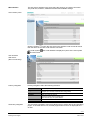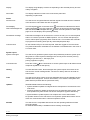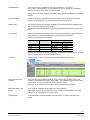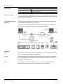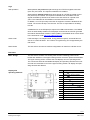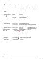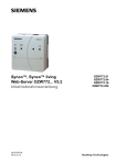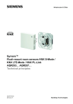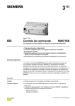
1
s 5 701 Web-Server TM For Synco , Synco TM OZW772... V5.2 living Web server OZW772… allows for remote plant control and monitoring via the web and Smartphone App. Four versions of the web server OZW772... are available: To connect 1, 4, 16, or 250 Synco devices from product ranges Synco 700, room controllers RXB/RXL, RDG/RDF/RDU room thermostats, and the QAX9… Synco living central apartment units. Operate web browser via PC/laptop or Smartphone. Operation via Smartphone App (iPhone and Android) Operation via Internet portal with auxiliary functions Operation and monitoring of KNX S-Mode devices (Lighting, blinds, energy and volume meters, etc.) Visualize the plants in the web browser based on standard plant diagrams and customized plant web pages. Connections: USB and Ethernet. Display fault messages in the web browser. Send fault messages to a maximum of 4 e-mail recipients. Periodic sending of system reports to a maximum of 4 e-mail recipients. Consumption data Recording, display, and sending to 2 e-mail recipients Create trends and send them to 2 e-mail recipients CE1N5701en 2014-10-15 Building Technologies Function "Energy indicator" for monitoring data points for energy-technical limit values, so-called “Green limits", and sending them to 2 e-mail recipients Web services for external applications via Web API (Web Application Programming Interface) Encrypted with https and TLS for e-mails. ACS790 functionality. Use Building Owners/operators End customers, HVAC and electrical installers. Real estate companies, real estate management companies. Building maintenance companies, energy and facility management. Apartments in single and multi-family homes. Office and administrative buildings, residential housing. Schools, gymnasiums, leisure facilities, hotels. Municipal buildings, smaller industrial buildings. Functions Commissioning Commissioning using a PC/laptop via web browser or ACS. ETS is used to configure KNX S-Mode components. Web operation Remote operation and monitoring and devices on one KNX network with web browser on PC/laptop and smartphone. Access via Internet portal or direct connection Simultaneously supports multiple users. User accounts for web operation (user groups, operating language). Set up visualized operation based on standard plant diagrams (loaded via HVAC Integrated Tool, HIT) or customized plant web pages. Access via portal Siemens offers with the Climatix IC / Synco IC Internet portal simple and secure access to web serves (available as of web server version 5.2). Benefits Simple and fast set up of access via the Internet – neither a fixed IP address, nor forwarding of a dynamic IP address, nor port forwarding (NAT/PAT) is required The portal provides additional functions: - Manage one or multiple plants - Central user management - Display of plant overview, state of Energy indicators, and alarms - Plant functional scope can be set for various plant roles - Logging fault messages as common faults - Send alarm notifications per e-mail - Secured communications through encryption (https) Access without portal (direct connection) The web server can be accessed directly via the Internet (without using the portal). A fixed IP address to the web server is required or a dynamic IP address with forwarding via a dynamic DNS server. In addition, the port forwarding must be configured on the router. A direct connection in parallel to the portal is also possible. 2 / 19 Siemens Building Technologies Web-Server OZW772... V5.2 CE1N5701en 2014-10-15 Web interface The web server interface is the same using the portal or via a direct connection. The portal has, however, additional functions and available settings. User interface portal Click the symbol to open the web server user interface under a new tab and is then the same as the view under a direct connection. The portal symbol and user name. and e-mail address is displayed in place of the user symbol User interface Web server (direct connection)) Primary navigation Primary navigation offers the following functions: Home Energy indicator Faults File transfer User accounts Device web pages Secondary navigation Menu-based plant and device operation. Display and operating of "Energy indicator" data points (Displayed only if a controlleri s connected with an Energy indicator) Display system faults. Create and manage trend functions Download consumption data and message history, upload documents, logos, and system definitions User administration. Create device list and operating pages. The secondary navigation (menu tree) allows users to select devices and operating pages. As of OZW version 5.0, the KNX pages defined in ETS as displayed here as well. 3 / 19 Siemens Building Technologies Web-Server OZW772... V5.2 CE1N5701en 2014-10-15 Display The display range displays content corresponding to the selected primary and secondary navigation. Plant state The display indicates no fault or the most serious plant fault depending on plant state. Faults Fault sources The web server recognizes failures and fault signals from KNX devices contained in the device list. Own faults also are recognized. Fault display, fault acknowledgement The LED signals a fault on the web server . LED blinks to indicate that a fault is unacknowledged. The LED continues to be lit for as long as the fault is pending after the fault is acknowledged with the button via web operation or ACS. (See page 10 for LED displays and operating buttons). Fault status message Fault status messages can be sent as an e-mail to as many as 4 e-mail recipients and/or via a service provider to SMS recipients. You can set the fault priority for each e-mail recipient (urgent/all). Each receiver has a "Time switch with calendar" to program three sending times per day and holidays/special days. Common fault On the Climatix IC/Synco IC Internet portal, faults are logged as common faults. The portal sends alarm notifications to the defined e-mail addresses in the event of a common fault. System report System messages The web server generates system reports and periodically sends the system operating state to e-mail recipients. Messages are sent as per the set time (hh:mm), message cycle interval (1...255 days), and priority (urgent/non-urgent). Connection test Press the button on the web server to send a system report to all defined e-mail recipients regardless of fault priority. History The last 500 fault events, fault messages and system reports are entered in the web server's circular message buffer. The event or history data can be read via web browser. Time The web server has a system clock with adjustable time zone and daylight saving/ standard time changeover. As clock time master, it can send the set system time (date and time) to KNX devices (clock time slave). Updates We differentiate between the following: System definition updates to integrate device descriptions of new devices in the web server. Firmware updates to update the web server to the latest firmware version. Firmware updates may also contain new device descriptions (system definitions). A system definition update requires one simple action via the web browser. No operator actions on the web server are required to update the firmware. Procedures are communicated when a firmware update is issued. ACS790 The web server is compatible with the service and operating software ACS790 V8.00 and higher. No ACS790 functionality is available when accessing via the portal. 4 / 19 Siemens Building Technologies Web-Server OZW772... V5.2 CE1N5701en 2014-10-15 Visualize plants Web server OZW772... allows for visualizing technical equipment (HVAC, electrical, energy values) in buildings via plant web pages. For example, a plant web page can be set up visualizing a plant with data points (max. 100 data points per plant web page) on a floor plan. In the event of a fault, users can quickly access the impacted locations. Double-click writable parameters to open a dialog box and edit the value. Example Plant web pages for ventilation plant Example Plant web pages for HVAC and lighting, blinds 5 / 19 Siemens Building Technologies Web-Server OZW772... V5.2 CE1N5701en 2014-10-15 Download plant diagrams You can download web-capable plant diagrams from the HIT online platform for standard applications on Synco 700 devices, room controllers RXB/ RXL, and room thermostats RDG/RDF/RDU. Create own plant web pages You can freely design plant web pages. As a hybrid form, you can also modify and extend downloaded plant diagrams. Web page elements Users can also embed additional data in a plant diagram such as energy values V5.0 or links to plant, function and maintenance descriptions or data sheets. Moreover, users can integrate external links allowing, for example, for direct browsing multiple plants. Users can embed current webcam images in a plant diagram. KNX S-Mode Integration of KNX S-Mode data points permits central control of heating, ventilation, air conditioning, and electrical installations. Data points recording by OZW can be used, for example, for trending, to depict the plant diagram or reused for thermal or electrical energy consumption. Number of S-Mode data points Version OZW772.01 supports 7 standard data points for system time and alarm info functions. For version OZW772.04/16/250, the following of data points can also be integrated: Data point sub-types 1 bit value 2 bit switching controlled 1 byte value 1 byte scene 2 byte value 4 byte value display Amount KNX interfaces No. 100 5 40 5 40 40 230 The web server OZW772.xx also assumes the KNX USB and KNX/IP interface, KNXnet/IP, using its built-in USB and Ethernet interfaces. Separate devices to connect the ETS to the KNX bus or via USB and Ethernet are no longer necessary. 6 / 19 Siemens Building Technologies Web-Server OZW772... V5.2 CE1N5701en 2014-10-15 Trend function The trend function is available in web server OZW772… as of V5.0. Any number of data points for connected devices can be logged at a selectable sample rate and queried using the trend function. Data points for devices integrated via KNX S-Mode are also available for the trend function. Trend channels 5 trend channels are available: Each trend channel can include up to 100 data points. The trend channel can be labelled using a plain text name. Sample rate The sample rate can be created individually for each trend channel. Sample rates from 1 second to 25 hours are available. The shortest possible sample rate over all 5 trend channels is 1 data point per second. Trend period Memory determines the possible trend period of a trend channel. The trend period varies with the number of selected data points and their sample rate. Examples for various trend channels: Interval 1 sec 5 sec 1 min 15 min Data points 1 5 10 100 Trend period Channel 1 14 days 30 days 210 days 371 days Channel 2…5 1.8 days 4.3 days 30 days 53 days Memory that is 7 times greater is available in trend channel 1 for long-term trending with a lot of data points, or short sample intervals. Operation A web browser or the ACS tool creates and manages trend functions. Data query per web browser The trend data can be downloaded for each channel using a web browser and viewed in a spreadsheet program or text editor. The calendar function permits limiting the trend data to a desired time period within the trend. Users can access the web server either local or remote via the Internet. Data transmission per e-mail Up to 2 e-mail recipients can be defined for the trend data. Each trend channel can send its data to one or both e-mail recipients. The send interval can be set individually for each trend. Import/Export Trend definitions can be imported to the web server or exported from the web server. 7 / 19 Siemens Building Technologies Web-Server OZW772... V5.2 CE1N5701en 2014-10-15 Consumption data trending The "consumption trend" function is available in web server OZW772… as of V3.0. The following devices are supported: Synco 700: RMU7x0B, RMH760B, RMK770 (as of V2.0), RMS705, RMS705B, RMB795, RMB795B Synco living: Central apartment unit QAX903, QAX913 OZW772 as of V5.0 Energy and volume meters that use KNX data points are supported with the integration of KNX S-Mode as of web server V5.0. The meter is connected directly or via KNX adapter to the KNX bus and transmits its data as per the configuration made in ETS. Meter Current consumption data is saved in the meters (legal requirement). QAX / Synco 700 Every 4 hours, central apartment unit QAX9… receives raw data via KNX radio. Synco 700 controllers generate the meter data via pulse inputs as per the configured values. Consumption data can be viewed on individual QAX central units or Synco controllers using the associated menus. Web server, local or remote The web server offers comfortable access to consumption data: Web browser operation users to navigate to the consumption data of the associated devices. Easier still: Or a consumption data file can be downloaded from the web server. The file contains a list of consumption data for all QAX units (apartment units) and Synco controllers. Users can access the web server either local or remote via the Internet. Web server, e-mail Consumption data can be sent periodically (set up via web server) to max 2 e-mail recipients (e.g. billing company). 8 / 19 Siemens Building Technologies Web-Server OZW772... V5.2 CE1N5701en 2014-10-15 Function "Energy indicator" The "Energy indicator" function is available in web server OZW772… as of V4.0. The following devices are supported: Synco 700: RMU7x0B, RMH760B, RMK770 (as of V2.0), RMS705B, RMB795B Synco living: Central apartment unit QAX903, QAX913, QAX910 (as of V3.0) Room controllers: RXB2x, RXL2x, RXB3x, RXL3x Room thermostats: RDF301, RDU341, RDGx00KN The web server uses the "Energy indicator" function to read selected data point values from the bus devices and to compare the values to energy-related limit values, or so-called "Green limits". The data points are also monitored for adherence to the "Green limits". As a result, the "Energy indicator" is displayed in the form of a tree leaf. Note The "Green limits" are used only together with the "Energy indicator" function. They do not represent process or safety limit values which trigger e.g. fault messages or turn off the plant in the event of limit violations. Web server, e-mail The "Energy indicator" can send its information periodically (adjustable via web server) to a maximum of 2 e-mail recipients. Tree leaf as "Energy indicator" Green leaf "Green leaf" Green tree leaf, leaf pointing up. Orange leaf "Orange leaf" Orange tree leaf, leaf pointing down. The "Green leaf" symbol indicates that a data point value has not exceeded its "Green limit", i.e. the value is within a "green" range in terms of energy consumption. The "Orange leaf" symbol indicates that a data point value has exceeded its "Green limit", i.e. the value is outside a "green" range in terms of energy consumption. Standard EN 15232 The "Energy indicator" function is based on standard EN 15232 "Energy efficiency in buildings". Example: "Energy indicator" web page function Web page with "Energy indicator" function; example with data points from "Room 1" and open dialog box to set data point value "Comfort heating setpoint" and its "Green limit" (for "Room 1"). 9 / 19 Siemens Building Technologies Web-Server OZW772... V5.2 CE1N5701en 2014-10-15 Web services The "Web Application Programming Interface" (Web API) is an interface to provide web services client to the web server. All web API functions are started via "http" or encrypted with "https". Each session stars with authentication at the web server. If "Home Control App" is installed on a smartphone, the app accesses, using the web services, via web API, data points for devices on the KNX network (Communication connection for smartphone, see page 12). Type summary Name Web server Web server Web server Web server KNX S-Mode For 1 Synco device 7 data points For 4 Synco devices 250 data points For 16 Synco devices 250 data points For 250 Synco devices 250 data points Product number OZW772.01 OZW772.04 OZW772.16 OZW772.250 Ordering and delivery When ordering, please specify the name and product number. Example: Web server OZW772.16 The web server is delivered in a cardboard box. The following is included in the package: Installation instructions G5701xx (multilingual). Package insert with activation key for portal access. Power cable, power supply AC 230 V. Ethernet cable. USB cable. 2 cable ties. 10 / 19 Siemens Building Technologies Web-Server OZW772... V5.2 CE1N5701en 2014-10-15 Equipment combinations The following Synco devices can be connected to the web server OZW772. Synco range Synco devices Universal controllers Heating controllers Boiler sequence controllers Central control units Switching & monitoring units Bus operator unit Room unit Central communication unit RMU7x0, RMU7x0B RMH760, RMH760B RMK770, RMK770 V2 RMB795, RMB795B RMS705, RMS705B RMZ792 QAW740 OZW771, OZW775 Data sheet no. N3144, N3150 N3131, N3133 N3132 N3121, N3122 N3123, N3124 N3113 N1633 N3117, N5663 Synco RXB/RXL Room controllers Room controllers Room controller Room controller Room controller Room controller RXB21.1, RXB22.1 RXL21.1, RXL22.1 RXB24.1 RXL24.1 RXB39.1/FC-13 RXL39.1/FC-13 N3873 N3877 N3874 N3878 N3875 N3876 Synco RDF/RDU/RDG Room thermostat for fan coils RDF301 Room thermostat for fan coils and lighting RDF301.50 Room thermostat for fan coils RDF600KN Touchscreen thermostat for fan coil RDF800KN Room thermostat for VAV RDU341 Room thermostat for fan coils RDG100KN Room thermostat for VAV RDG400KN N3171 N3171 N3171 N3174 N3172 N3191 N3192 Synco living Central apartment unit Central apartment unit Central apartment unit N2741 N2707 N2740 Synco 700 QAX903 QAX910 QAX913 Product documentation Document type Data sheet (this document)) Installation instructions (package insert) Commissioning instructions CE declaration of conformity Environmental product declaration Document no. N5701 G5701 C5701 T5701 E5701 KNX bus Data sheet Basic documentation N3127 P3127 ACS790 software Data sheet N5649 Web server OZW772… 11 / 19 Siemens Building Technologies Web-Server OZW772... V5.2 CE1N5701en 2014-10-15 Technical design Web browser Devices PC/Laptop (1024 x 786) Smartphone Requirements Internet Explorer V10.0 or higher. Firefox V18.0 or higher. Specific for device Number of browsers Any number of browsers can be used simultaneously. The maximum data throughput rate is distributed among the browsers. Operation slows down as the number of users increases accordingly. Operation, monitoring, alarming Communication connections for local commissioning (USB) and remote operation, remote monitoring and alarming via Ethernet. The web server is not suited for direct connection to the Internet, but rather must be connected via a firewall. A router typically includes a firewall. Interfaces USB The USB interface directly connects the PC/laptop on site. The required USB cable type A – type Mini-B is delivered with the device. Ethernet The router/network is connected to the Ethernet RJ45 plug. The Ethernet interface features Auto-MDI(X) for crossed and non-crossed Ethernet cables. An Ethernet category 5 cable is supplied. KNX The KNX bus is connected to the CE and CE connection terminals labeled "KNX". See data sheet N3127 for more information on the KNX bus. 12 / 19 Siemens Building Technologies Web-Server OZW772... V5.2 CE1N5701en 2014-10-15 Logs Web operation Web operation via portal takes place through an HTTPS encrypted connection (Port 443) via TCP/IP. The required certificate is accredited. Web operation without portal takes place through an HTTPS encrypted connection (Port 443) via TCP/IP. The required certificate is not accredited. The self signed certificate by Siemens has saved on the web server for a period of 20 years. The certificate can be installed in the web browser as needed. In addition, an HTTP (Port 80) connection is supported. Port 80 is disabled as delivered. The access via http is not secured. The user is responsible for enabling Port 80. A RNDIS driver on the PC/laptop is required for USB communication. The RNDIS driver is automatically installed on PC/laptops connected to the Internet (provided the network administrator enables "online update"). The RNDIS driver is also saved to the web server under http://<IP address>/drivers/. Send e-mail Fault messages, consumption data, energy indicator reports, and trend files are sent in an e-mail via SMTP. The e-mail is encrypted using TLS if supported by the mail server. DHCP Client The web server can take its network configuration as client from a DHCP server. Execution Basic design The web server consists of a housing lower section containing printed circuit boards with interfaces. The upper housing section covers the printed circuit boards. The upper housing section contains the LED displays and one operating button. The connection terminals and additional display and operating elements are located under the removable cover for the upper housing section. All display and operating elements are labeled. Display and operating elements Pos Designation 1 LED Mode, portal connection display and "Energy indicator" 2 LED 3 LED field bus 2 (reserve) 4 LED fault 5 LED addressing mode 6 Remote button 7 Addressing mode button 8 "Message suppression" switch 9 Switch 2 (no function) 10 KNX bus connection terminals 11 Operating voltage connection 12 USB connection Mini-B 13 Ethernet connection, RJ45 plug 13 / 19 Siemens Building Technologies Web-Server OZW772... V5.2 CE1N5701en 2014-10-15 LED indication 1 (red/green/orange) Dark Steady red Flashing red Steady green Lit orange Flashing green green / orange No operating voltage DC 24 V Web server starts operating system. Web server starts application. Web server operational, "Energy indicator" = "Green leaf" Web server operational, "Energy indicator" = "Orange leaf" Web server operational, connected to the portal (LED 0.8 s on, 0.2 s off) Dark Lit Flashing No bus power. KNX operational. Communication on KNX. 3 Field bus 2 (reserve) Dark No function. 4 Fault Dark Lit Flashing No fault (normal operating state). Acknowledged fault. Unacknowledged fault. Dark Lit KNX addressing mode off. KNX addressing mode on. 6 Remote button Short (< 2 s) Long (> 6 s) Acknowledges fault message. Send the system report to the fault e-mail recipient (not to consumption data, and "Energy indicator" and trend data recipient). 7 Addressing mode Short (< 2 s) Press once: Press again: Button combinations and Long (> 6 s) Simultaneously press and restores default factory settings. All configuration data and settings are reset. The device list, plant diagrams, and unsent messages are deleted. History data is not deleted. 2 (green) (red) 5 Addressing mode (red) Operating buttons KNX addressing mode On KNX addressing mode off. Switches 8 Message suppression Position ON Position OFF Sending messages is suppressed. Sending messages permitted. 9 DIP switch 2 Switch settings. No function. 14 / 19 Siemens Building Technologies Web-Server OZW772... V5.2 CE1N5701en 2014-10-15 Notes Mounting The web server can be mounted in a panel, distribution box, or on a wall. Include space for wiring when planning. Make sure service can easily access the unit and the unit is ventilated properly. Standard mounting Wall mounting Mounting position Mounting and dimensions On standard rail TH 35-7.5. Attached with 2 screws. Horizontal or vertical. See "Dimensions". Install Important notes Observe the following when installing: Run fuses, switches and wiring as per local regulations for electrical installations. We do not recommend plant monitoring via USB interface in environments with strong electromagnetic interference (e.g. in industrial environments with electrical welding equipment). See "Technical data" for electromagnetic compatibility. Operating voltage The supplied AC 230 V power supply provides the DC 24 V operating voltage for the web server. Wiring The operating voltage, USB and Ethernet plugs are located on the upper part of the housing. The terminals on the device for the KNX bus are located under the removable cover. Connection terminals Commissioning Connections The connection terminals are designed for wire diameters of min. 0.5 mm or cross2 2 sections of 0.25...1.5 mm or stranded wire cross-sections of 0.25...1.0 mm . Web-Server is commissioned directly via the portal with a PC/Laptop. A web browser required on the PC/Laptop. The web server can be commissioned locally via USB or with ACS790. The supplied USB cable type A – Type Mini-B connects the web server to the PC/laptop. Additional information is available in the included installation guide G5701 or commissioning guide C5701 at the Download Center at www.siemens.com/ozw772 manual. ETS configures and commissions KNX S-Mode devices and is described in the commissioning guide C5701. Router A suitable router is required for remote operation via Internet. The router must support NAT/PAT to access via the portal or via a direct connection using a fixed IP address. For a direct connection using a dynamic IP address, it must also support a dynamic DNS server. IP address The IP address via USB is set: 192.168.250.1. Default setting for IP address via Ethernet: 192.168.251.1. The network administrator must provide an IP address for the web server before you can connect the web server via Ethernet to a managed network. 15 / 19 Siemens Building Technologies Web-Server OZW772... V5.2 CE1N5701en 2014-10-15 User groups User accounts are created and assigned to specific user groups for customized user operation. End user Access to end-user data and fault overview. Operate and monitor via menu tree and plant diagrams. Administer own user accounts. Service Same as end user. In addition: Access service data. Create, download, and manage trend data Download consumption data and message history. Upload customized logos and documents. System definitions update. Update device web pages. Administrator Same as service. In addition: Edit device list. Create device web pages. Create, copy, change, and delete plant diagrams. Select "Energy indicator" data points, as needed, edit default values for the data points and/or "Green limits". Administer all user accounts. Maintenance The OZW772… web server is maintenance free (no battery changes, no fuses). Use only a dry towel to clean the housing. Repair The OZW772… web server cannot be repaired on site. If faulty, return to the Repair Center at the relevant Regional Company. Disposal The devices are considered electronic waste in terms of the European Directive 2012/19/EU and may not be disposed of has household waste. Use only proper channels to dispose the device. Comply with all local, applicable laws and regulations. 16 / 19 Siemens Building Technologies Web-Server OZW772... V5.2 CE1N5701en 2014-10-15 Technical data Power cable for web server OZW772... Web server OZW772… Function data KNX bus USB Ethernet Directives and standards Operating voltage Rated voltage "Euro plug" AC 230 V 15 % AC 230 V EN 50075 and VDE 0620-1 Frequency 50 / 60 Hz Power consumption (including web server OZW772...) 3 VA typical Protection class II Output voltage SELV 24 VDC Fusing of supply lines Max. 16 A Cable length (distance from AC 230 V plug to web server) Max. 1.6 m Operating voltage SELV 24 VDC 5%, 625 mA max. Power consumption 2 W typical Clock reserve Min. 72 hours Device list OZW772.01 OZW772.04 OZW772.16 OZW772.250 1 Synco device Up to 4 Synco devices Up to 16 Synco devices Up to 250 Synco devices Interface type 2-wire bus Bus load number KNX bus power consumption TP1 (twisted pair, 1 cable pair) CE+, CE- (non exchangeable) E 15 6 mA. Permissible line length and cable types See data sheet N3127. Connection, screw terminals for Solid/stranded wire (twisted or with ferrule) 1 solid wire per terminal 1 stranded wire per terminal. min. Ø 0.5 mm 0.25...1.5 mm2 0.25...1.0 mm2 Interface type Device class Baud rate USB V2.0 RNDIS Max. 12 Mbps (full speed) Connecting cable Cable length Cable type for connection to PC/laptop Cable type for connection to OZW772… Max. 3 m USB type A USB type Mini-B Interface type Bitrate Protocol Recognition 100BaseTX, IEEE 802.3 compatible Max. 100 Mbps TCP/IP Auto MDI-X. Connection, plug Cable type Cable length RJ45 plug (screened) Standard Cat-5, UTP or STP Max. 100 m. Product standard EU conformity (CE) EN 60950-1 Information technology equipment – Safety CE1T571xx *) RCM conformity CE1T5711en_C1 *) Environmental compatibility The product environmental declaration CE1E5711en*) contains data on environmentally compatible product design and assessments (RoHS compliance, materials composition, packaging, environmental benefit, disposal). Degree of protection Protective category IP30 to EN 60529 Protection class III as per EN 60950-1 *) The documents can be ordered at http://siemens.com/bt/download. 17 / 19 Siemens Building Technologies Web-Server OZW772... V5.2 CE1N5701en 2014-10-15 Degree of protection Degree of protection IP30 to EN 60529. Protection class III as per EN 60950-1. Operation Climatic conditions Temperature (housing with electronics) Humidity Mechanical conditions IEC 60721-3-3 Class 3K5 0 …50 °C 5…95% r. h. (non-condensing) Class 3M2 Transport Climatic conditions Temperature Humidity Mechanical conditions IEC 60721-3-2 Class 2K3 25...70 °C < 95% r.h. Class 2M2 Upper housing section PC + ASA, RAL 7035 (light-gray) Lower housing section PC + ASA, RAL 5014 (dove blue). Dimensions Length x width x height (max. dimensions) 87.5 mm x 90 mm x 40 mm Weight Web server OZW772… Web server with packaging, installation instructions, power unit, USB and Ethernet cable, cable straps. 0.136 kg Packaging Cardboard box Auto Medium Dependent Interface - Crossed Auto-MDI(X) Dynamic Domain Name System Dynamic DNS Dynamic Host Configuration Protocol DHCP Energy Cost Allocation ECA Engineering Tool Software ETS HVAC Integrated Tool von Siemens HIT Hyper Text Transfer Protocol HTTP Hyper Text Transfer Protocol Secure HTTPS Internet Protocol IP KNX System installation methods KNX S-Mode Konnex KNX Network Address Translation NAT Port and Address Translation PAT Remote Network Driver Interface Specification RNDIS Simple Mail Transfer Protocol SMTP Shielded Twisted Pair STP Transport Layer Security TLS Transmission Control Protocol TCP Universal Serial Bus USB Unshielded Twisted Pair UTP Web Application Programming Interface Web API Ambient conditions Materials and colors Terms, abbreviations 0.589 kg. 18 / 19 Siemens Building Technologies Web-Server OZW772... V5.2 CE1N5701en 2014-10-15 Connection diagrams Connection diagram KNX connection terminals Pin assignment DC 24 V plug 1 2 24 VDC (+) GND (–) Dimensions 2009-2014 2009 - 2012Siemens SiemensSwitzerland SwitzerlandLtd Ltd Siemens Building Technologies Web-Server OZW772... V5.2 19 / 19 Subject to change CE1N5701en 2014-10-15