1
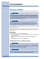
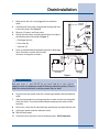
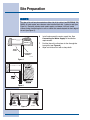
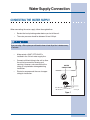
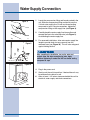
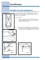
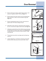
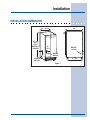
Installation
INSTALLATION DIMENSIONS
24”
(61)
14 - 15/16”
(37.9)
34 - 1/8”
(86.7)
FULL
RETRACT
HEIGHT
5”
(12.7)
WATER
VALVE
WATER
DRAIN
WATER
OUTLET
21 - 3/4”
(55.2)
Figure 1
Drain Installation
INSTALLING THE DRAIN
!
CA
UTION
CAUTION
PLEASE READ all instructions completely before attempting to install or operate the
unit. All ice makers require a connection to the water supply and improper hook-up can
result in substantial property damage! All water and drain connections MUST BE made
by a licensed/qualified plumbing contractor. Failure to follow recommendations and
instructions may result in damage and/or harm.
!
CA
UTION
CAUTION
Plumbing installation must observe all state and local codes. All water and drain
connections MUST BE made by a licensed/qualified plumbing contractor. Failure to
follow recommendations and instructions may result in damage and/or harm.
Model E15IM60E can be installed using a gravity drain or can use a factory installed
or equivalent drain pump.
Follow these guidelines when installing drain lines to prevent water from flowing
back into the ice maker storage bin and/or potentially flowing onto the floor causing
water damage:
Gravity Drain
• Drain lines must have a 5/8 inch inside diameter.
• Drain lines must have a 1 inch drop per 48 inches of run (1/4 inch per foot) and
must not create traps.
• The floor drain must be large enough to accommodate drainage from all
drains.
• Insulate the bin drain line to prevent condensation.
Ice Makers With Factory Installed Drain Pump
!
CA
UTION
CAUTION
Before installing an icemaker with a factory installed pump, it is extremely important to
check and test all hose connections at the drain pump. There is a possibility that hose
connections may have loosened during shipment.
!
WARNING
To prevent accidental electrocution, make certain that the floor surfaces surrounding
the unit are dry whenever power is removed from, or applied to the unit.
Drain Installation
1
Make certain the unit is not plugged into an electrical
outlet.
2
Carefully push the power cord grommet through the hole
in the back panel. See Figure 2.
3
Remove 12 screws and back panel.
4
Check that the clamps and hose connections are tight at
the following areas illustrated in Figure 3:
9
• Discharge tube (A)
• Drain tube (B)
• Vent tube (C)
5
Place a suitable container beneath the pump’s discharge
tube. (Container must be able to hold a
minimum of one gallon of water.)
B
Figure 2
B
C
A
BACK VIEW
SIDE VIEW
UL184-2
Figure 3
!
WARNING
Back panel serves as a guard. DO NOT put your hands inside the ice maker cabinet or
attempt to touch any components except the discharge tube during testing. Failure to
follow this warning could result in serious personal injury or death.
6
Plug the ice maker power cord into a properly grounded, polarized electrical
outlet.
7
Verify pump operation by pouring one gallon of water into the ice storage bin
of the ice maker. The pump should energize and pump the water into the
container.
8
At this time, verify that all tube and clamp connections are tight and leak free.
9
Unplug unit power cord from electrical outlet.
10 Reinstall back panel.
11
Continue to the next step in the installation process, Site Preparation.
10 Drain Pump Connection
CONNECTING A DRAIN PUMP
If a gravity drain connection is not available, and you have not purchased the
E15IM60E with factory installed pump, we strongly recommend the use of the
Electrolux EIMP60 drain pump. The Electrolux EIMP60 drain pump is available
through your Dealer, or direct from Electrolux with complete installation instructions.
If a pump other than the Electrolux EIMP60 drain pump is to be used, it must meet
the following specifications:
•
It must be UL listed and have a UL listed, 120 VAC, 3-wire grounded power
cord.
•
It must have overall maximum outside dimensions of 8-3/4" wide x 5-3/4"
deep x 7-3/4" high.
•
It must have a minimum flow rate of 15 gallons per hour at 10 feet of lift.
•
It must have a sealed sump which does not allow water leakage in the case
of a power outage, restricted drain or pump failure.
•
It must have a check valve in the discharge line to prevent waste water return
to the pump.
•
It must have an overflow protection control which will shut off power to the ice
maker in the event of a pump failure.
•
It must have an operating temperature range of 50°F to 110°F (10°C to 43°C).
!
CA
UTION
CAUTION
In the event of a power outage, restricted drain or pump failure, the failure to use the
Electrolux EIMP60 drain pump or a pump with the above listed specifications, could
result in substantial water leakage and pooling with severe and costly water damage
and related consequential damages and harm.
Site Preparation
PREPARING THE SITE
IMPOR
TANT
IMPORT
It is extremely important that the unit is level. If it is not level, the ice mold will not fill
evenly. This can cause a reduction in ice rate, uneven sized cubes or water spilling into
the storage area which will cause the ice in the bin to melt pre-maturely. Remember that
floors near drains have a tendency to slope towards the drain.
1
Position the unit on a flat, level surface, capable of supporting the entire
weight of the unit. Remember that the unit will be significantly heavier once it
is fully loaded.
2
The surrounding air temperature must be at least 50°F (10°C) but must not
exceed 110°F (43°C).
3
The unit must not be located near heat-generating equipment or in direct
sunlight.
!
DANGER
ELECTROCUTION HAZARD!
Electrical Grounding Required. This appliance is equipped with a three prong
(grounding) polarized plug for your protection against possible shock hazards.
• NEVER remove the round grounding prong from the plug.
• NEVER use a two-prong grounding adapter.
• NEVER use an extension cord to connect power to the unit.
Where a two-prong wall receptacle is encountered or a longer power cord is required,
contact a qualified electrician to have it replaced in accordance with applicable
electrical codes.
4
The unit must be located to allow clearance for water, drain and electrical
connections in the rear of the ice maker.
5
Connect the unit to a grounded and polarized 115 VAC, 60 Hz, 15 A circuit
(normal household current).
6
Avoid connecting the unit to a Ground Fault Interruptor (GFI). GFIs are prone to
nuisance tripping which will cause the unit to shut down. GFIs are generally not
used on circuits which power equipment that must run unattended for long
periods of time.
7
The unit must be installed according to your local codes and ordinances.
12 Site Preparation
NO
TE
NOTE
The door of the unit may be mounted on either side of the cabinet (see REVERSING THE
DOOR). All units require zero clearance when installed flush with a cabinet or wall (see
Figure 4). Electrolux stainless steel models require a minimum 2-3/4 inch handle
clearance when installed against a wall or cabinet that extends beyond the front edge of
the unit (see Figure 5).
CABINET
OR WALL
DOOR
SWING
0"
CLEARANCE
NEEDED
UL124A
Figure 4
2 - 3/4”
Figure 5
EXHAUST
Figure 6
INTAKE
6
Install and connect the water supply line. See
Connecting the Water Supply for installation
requirements.
7
Position the unit to allow free air flow through the
front grille (see Figure 6).
8
Wipe out inside of unit with a damp cloth.
Water Supply Connection
CONNECTING THE WATER SUPPLY
When connecting the water supply, follow these guidelines:
•
Review the local plumbing codes before you install the unit.
•
The water pressure should be between 20 and 120 psi.
CA
UTION
CAUTION
!
If you are using a filter system you will need to have at least 20 psi for 3 minutes every
15 minutes.
•
Make certain a SHUT-OFF VALVE is
installed in the 1/4 inch water supply line.
•
Connect sufficient tubing to the unit to allow
the unit to be moved for cleaning and
servicing. However, make certain that the
tubing is not pinched or damaged during
installation.
•
WATER
CONNECTION
Electrolux recommends the use of copper
tubing for installation.
UL103_CO
Figure 7
Water Supply Connection
Figure 8
1
Locate the compression fitting and ferrule packed in the
unit. Slide the compression fitting and ferrule over the
1/4 inch water supply line. Do not use thread sealing
compound or tape. Using two wrenches, tighten the
compression fitting on the supply line (see Figure 8).
2
Carefully bend the water supply line into position and
connect the line to the solenoid valve (see Figure 9).
Avoid kinking the water supply line.
3
For recessed installations, allow extra water supply line
length to provide slack for easy removal from the
recessed area (see Figure 10). This will also safeguard
against kinking the line.
UL134
Figure 9
!
CA
UTION
CAUTION
After completing the installation, turn on the water and
recheck water and drain connection for leaks. Apply
additional tightening if needed. Do NOT use thread sealing
com-pound or tape.
Figure 10
4
Plug in the power cord.
5
Gently push the unit into position. If desired the unit may
be recessed into cabinet or wall.
6
Allow at least 1-1/2 inches clearance behind the unit for
electrical, water supply and drain connections.
Leveling
LEVELING THE UNIT
IMPOR
TANT
IMPORT
It is extremely important that the unit is level. If it is not level, the ice mold will not fill
evenly. This can cause a reduction in ice rate, uneven sized cubes or water spilling into
the storage area which will cause the ice in the bin to melt pre-maturely. Remember that
floors near drains have a tendency to slope towards the drain.
1
Use a level to check the levelness of the ice maker
from front to back and from side to side (see Figure
11).
2
If the ice maker is not level, adjust the feet on the
corners of the unit as necessary (see Figure 12).
3
Check the levelness after each adjustment and
repeat the previous steps until the unit is level.
CHECK
LEVEL
Figure 11
Figure 12
TURN FOOT TO ADJUST
Door Reversal
REVERSING THE DOOR (SOME MODELS)
All Electrolux units may be left or right hand opening. The door
opening is easily reversed by moving the hinge hard-ware to the
opposite side (see Figure 13).
To reverse the door:
Figure 13
1
Remove top hinge screw pin (7/64" Allen wrench) from
cabinet (see Figure 14). Remove door by tilting forward
and lifting off bottom hinge pin.
2
Remove plastic screw plugs (3 top and 3 bottom) from
new hinge location (see Figure 15), and remove hinge pin
hole plug in top of door (see Figure 16). Do not discard.
Figure 14
SCREW
PLUGS
Figure 15
Hole
Plug
Figure 16
Door Reversal
HINGE
SCREW
PIN
3
Remove top hinge (3 screws), reinstall hinge screw pin, and
remount on opposite side BOTTOM (see Figure 17).
4
Remove the two door closer inserts from the existing bottom
hinge and install as shown on the new bottom hinge (see
Figure 18).
5
Remove existing bottom hinge (3 screws) and remount on
opposite side TOP. Remove hinge screw pin.
6
With bottom of door facing up, remove pivot plate (2 screws),
flip over, and remount on opposite side of door (see Figure 19).
7
Holding door upright with top of door tilted forward, place hole of
door pivot plate on bottom hinge screw pin (see Figure 20). Be
sure that the bosses on the closers align with holes in hinge
and hinge plate.
8
Tilt top of door into position in top hinge and install top hinge
screw pin.
9
In empty hinge holes, install plastic screw plugs (3 top and 3
bottom) and door hole plug (1,door top) removed in step 2.
Figure 17
UL313
DOOR
CLOSER
INSERTS
BOSS
Figure 18
UL312
Figure 19
UL319
Figure 20
BOSS
CLRCO008