1
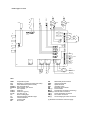
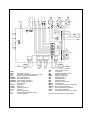
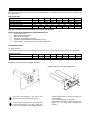
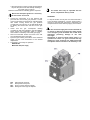
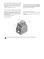
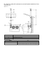
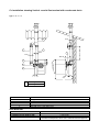
Gas room sealed unit heaters 2 stage
TECHNICAL INFORMATION ASSEMBLY
INSTRUCTIONS, USE AND MAINTENANCE
RS/UHA-2
BENSON HEATING
LUDLOW ROAD
KNIGHTON
POWYS
LD7 1LP
MAY 2003
Benson Heating is a divison of
Benson Climate Systems Ltd
COMPLIANCE NOTICES
The Benson RS/UHA2 range of warm air heaters detailed herewith are manufactured for Benson Heating within the
parameters of ISO 9002.
The Benson RS/UHA2 Range has been independently tested and assessed, and has been found to meet the Essential
Requirement of the following European Directives:
Gas appliance Directive (90/396/EEC)
Machinery Directive (89/392/EEC) 91368/EEC 93/44/EEC 93/65/EEC
Low Voltage Directive (73/23/EEC
Electromagnetic Compatibility Directive (98/336/EEC and 91/31/EEC)
Product Liability Directive (65/374/EEC)
The manufacturer has taken reasonable and practical steps to ensure that Benson RS/UHA2 Range of Heaters are safe
and without risk when properly used. These heaters should therefore only be used in the manner and purpose for which
they were intended, and in accordance with the recommendations detailed herewith.
The heaters have been designed, manufactured, assembled, inspected, and tested, with safety and quality in mind, there
are certain basic precautions which the installer and user should be aware of, and they are strongly advised to read the
appropriate sections of the information pack accompanying the heater, prior to installation or use.
Benson Heating supports all new products being supplied to their customers with a comprehensive information pack; this
clearly defines mandatory instructions for the safe installation, use, and maintenance, of the appliance(s).
Where proprietary items are incorporated into Benson Heating products, detailed information and instructions are also
provided as part of the information pack.
It is the responsibility of the installer, owner, user, or hirer, of such products supplied by Benson Heating, to ensure that
they are familiar with the appropriate information/manuals, supplied by the manufacturer, and that they are suitably
aware of the purpose of the manuals and the safety instructions. In addition, operators must be suitably trained in the use
of the appliance so as to ensure its continued safe and efficient use.
Benson Heating has a commitment to continuous improvement, and therefore reserves the right to amend or change the
specification of the RS/UHA2Heater range subject to agreement from The Notified Body.
Contained within the text of the manual, the words 'Caution' and 'Warning' are used to highlight certain points.
Caution is used when failure to follow or implement the instruction(s) can lead to premature failure or damage to the
heater or its component parts.
Warning is used when failure to heed or implement the instruction(s) can lead to not only component damage, but also
to a hazardous situation being created where there is a risk of personal injury.
Notified Body PIN Reference is
RANGE
Type
Model
1
RS/UHA2 50
2
RS/UHA2 80
3
RS/UHA2 105
4
RS/UHA2 140
5
RS/UHA2 200
6
RS/UHA2 260
7
RS/UHA2 325
Code
3TAIT2C016
3TAIT2C026
3TAIT2C036
3TAIT2C046
3TAIT2C066
3TAIT2C086
3TAIT2C106
INDEX
GENERAL
Description of equipment
Identification
Description
Identification
Description
Technical data
Wiring diagram
Remote control connections
Regulating air flow
page.
“
“
“
“
“
“
“
“
FOR THE USER
Operation
Servicing
Heater indication lights
Receipt of product
Transport
Dimension
“
“
“
“
“
“
FOR THE INSTALLER
Location
Wall bracket dimensions
Gas connection
Flue and combustion options
Electrical control panel
Electrical connections
“
“
“
“
“
“
TECHNICAL ASSISTANCE SERVICE
Pre commissioning checks
Initial start up
Gas conversion
Thermostat operation
Control
Maintenance
Fault finding
“
“
“
“
“
“
“
Heaters type 1-2-3-4-5
C
EVG1-II°
EVG1-I°
TR
C
SND
FAN 1
FAN 2
LM
N
I°
J12
II°
SF
F2
J15
J10
LB
N
IMT
J1
LL
J13
J18
RST
J16
MS
TA
J14
J2
J11
J17
J8
J4
J7
RSTR
VM
SE
IGN1
NA
NC
COM
EF
EA1
ION
PA
KEY:
SND
TR
LM
EVG1-I°
EVG1-II°
C
FAN 1
FAN 2
F1-F2
LF
LL
LB
RST
EF
Temperature probe
Regulatory control thermostat (auto reset)
LIMIT thermostat (manual reset)
Gas solenoid valve1
Second stage gas valve 2
Fan capacitor
Axial fan 1
Axial fan 2 (type 5)
Line fuse (6,3 A)
Green working light
High temperature indication light
Lockout indication
Lockout reset
Flue venter
PA
IGN1
EA1
ION
SE
IMT (*)
MS (*)
RSTR (*)
TA (*)
VM (*)
SF (*)
Differential pressure switch
Ignition transformer
Spark electrode
Ionisation probe
Electrical control board
Fused isolator
Fire damper connection (accessory)
Remote reset connection
Room thermostat connection
Fan switch connection
Second stage gas valve connection
(*) External to the heater customer supply.
230V 50Hz
J6
L
J9
J5
F1
LF
Heater type 6-7
C
C
EVG1-II°
EVG2-II°
TR
EVG1-I°
EVG2-I°
C
SND
FAN 1
FAN 3
FAN 2
LM
N
I°
J12
II°
SF
IMT
J15
LB
J10
J1
LL
N
J6
L
F2
J13
J18
RST
J16
MS
TA
J14
J2
J11
J17
J8
J4
J7
RSTR
VM
SE
IGN1
EA2
NA
NC
EA1
COM
IGN2
KEY:
SND
TR
LM
EVG1-I°
EVG2-I°
EVG1-II°
EVG2-II°
C
FAN 1
FAN 2
FAN 3
F1-F2
LF
LL
LB
EF
Temperature probe
Regulatory control thermostat (auto reset)
LIMIT thermostat (manual reset)
Gas solenoid valve 1
Gas solenoid valve 2
Second stage gas valve 1
Second stage gas valve 2
Fan capacitor
Axial fan 1
Axial fan 2
Axial fan 3(Type 7)
Line fuse
Green working light
High temperature indication light
Lockout indication
ION
PA
RST
EF
PA
IGN1
IGN2
EA1
EA2
ION
SE
IMT (*)
MS (*)
RSTR (*)
TA (*)
VM (*)
SF (*)
Lockout reset button
Flue venter
Differential pressure switch
Ignition transformer 1
Ignition transformer 2
Spark electrode 1
Spark electrode 2
Ionisation probe
Electrical control board
Fused isolator
Fire damper connection (accessory)
Remote reset connection
Room thermostat connections
Fan switch connections
Second stage gas valve connection
(*) External to the heater customer supply.
230V ~ 50Hz
J9
J5
F1
LF
GAS CONVERSION
The heaters are supplied ready for use with (G20) Natural Gas as per the table below Conversion kits are available from
the manufacturer:
Natural Gas (G20)
TYPE
Number of injectors
Diameter of injectors
Gas supply pressure
Head pressure high fire
Head pressure low fire
1
1
3,10
2
1
410
3
1
480
11,0
6,0
13,0
7,0
13,0
6,5
4
1
555
20
13,0
6,5
5
2
500
6
2
540
7
4
450
10,0
7,0
13,0
6,5
10,5
5,0
N°
mm/100
mBar
mBar
mBar
BEFORE CHANGING INJECTORS ENSURE GAS SUPPLY IS ISOLATED
INSTRUCTIONS FOR CONVERSION TO PROPANE GAS G(31)
1.
Change the injectors
2.
Adjust the gas inlet pressure
3.
Adjust the head pressure
4.
Fit primary air diaphragm (if required )
5.
Fit adhesive label supplied with kit indicating gas type
6.
Ensure settings are correct as per the manual and data plate
CHANGE INJECTORS:
To change injectors:
Unscrew the natural gas injectors and replace them with the correct size injectors for propane as shown in table below:
Propane gas (G31)
TYPE
Number of injectors
Diameter of injectors
1
1
190
2
1
250
3
1
280
4
1
335
5
2
285
6
2
320
7
4
255
N°
mm/100
Replacing injectors single manifold (type 1-2-3-4-6)
Replacing injectors 2 per manifold (type 5-7)
Check the size stamped on the side of the
injector is correct to the data in the manual.
Ensure that the new injectors are correctly fitted
in the manifold and are gas tight, When the
conversion is complete fix the transfer supplied
with the kit showing the correct gas pressure on
to the manifold
Test for gas soundness on completion
Ensure that the aluminium washers supplied for
(types 5–7) are fitted when changing the
injectors.
If the gas line has not been correctly purged ignition
may not take place at the first attempt resulting in
the heater going to lockout
Reset the lockout before re starting ignition sequence
The heater must only be operated with the
burner compartment door(s) closed
Before each attempt at ignition it is necessary
to wait at least 10 seconds
STOPPING
•
•
•
•
•
Connect the manometer on to the pressure test
point PM and check inlet gas pressure if correct
connect manometer to test point PV and start heater
with heater running ensure the gas pressure
corresponds to that shown on the data plate adjust
by altering the screws RP1 and RP2 on the gas
valve
Check that the gas consumption reading
corresponds with that indicated in the TECHNICAL
DATA section Set on/standby switch to standby
when heater is sufficiently cool isolate gas supply
Remove manometer ensure the screw at the test
point is tightened test for gas leaks
Open the gas isolating cock switch on the electrical
supply set the room thermostat to the desired
temperature.
The heater is now ready for operation
GAS VALVE
Model SIT 843 (two stage)
PM
PV
RP1
RP2
Inlet pressure test point.
Head pressure test point
Cross cut screw low fire adjuster
Hexagonal screw high fire adjuster
To stop the heater use only the room thermostat Set it
to the minimum temperature The fan will stop after 3
minutes or when the heat exchanger is sufficiently cool
If required switch off the electricity supply at the isolator
!
The main electrical supply must not be switched off
or used as a method of stopping the heater except
in an emergency until the heater has cooled down
sufficiently preventing damage to the heat
exchanger
Interruption of electrical supply whilst heater is in
operation will cause it to go to overheat and may
damage the heat exchanger the LIMIT thermostat
will operate and this will have to be manually re set.
Assembly of primary air diaphragm:
Diagram showing the fitting of a primary air
diaphragm to single burner manifold (1-2-3-4-6)
Diagram showing the fitting of a primary air
diaphragm for a two burner manifold type (7)
Warning the diaphragm plates should only
be used when using propane gas G31.
GAS PRESSURE REGULATION
To regulate the gas inlet pressure :
•
Connect a manometer onto the gas valve test
point (PM)
•
Adjust the inlet gas supply regulator (customer
installation) to pressure indicated on data
plate:
Gas conversion adhesive label:
Once the heater has been converted to propane ensure
that the correct label is fitted to the burner overtop of
the factory fitted one covering it completely. It is
recommended that the diameter of the nozzles be
checked also that the pressure corresponds to that
shown on the data plate provided
Ensure that all of the additional gas components are
correct for the installation (including storage tank, pipes
and pressure valves etc
Ensure that the pressure regulators are sealed after
carrying out the conversion.
Propane gas (G31)
TYPE
Gas supply pressure
Head pressure max
Head pressure min
To regulate the gas head pressure to the burner:
•
Connect a manometer onto the gas valve test
point (PV)
•
Adjust the pressure regulating adjusters RP1/
RP2 as detailed on next page to obtain correct
pressures indicated in table below:
1
2
3
35,5
20,0
35,0
18,0
35,5
18,5
4
37
35,5
18,0
Gas inlet pressure must not exceed 60 mbar at the gas valve inlet.
5
6
7
34,5
18,0
35,5
18,0
34,5
18,5
mBar
mBar
mBar
Gas valve head pressure setting high fire Propane G31:
When setting the gas pressure for propane high fire
(second stage ) contact SF should be closed the high
fire pressure adjusting screw on the gas valve must be
excluded.
Connect a manometer on test point PV
Remove the plastic cover from the adjuster RP1 RP2
With a screw driver hold the adjuster RP1 stationary
and using a spanner, screw adjuster RP2 clockwise to
the bottom of the thread until the correct pressure
according to the data plate is achieved .
Gas valve head pressure setting low fire Propane G31 :
When setting the gas pressure for propane low fire
(first stage) contact SF should be open. The low fire
pressure should be adjusted to the settings shown on
the data plate and the data in the manual provided by
adjusting screw RP1
Clockwise increases the pressure
Anti clockwise to decrease the pressure
On completion replace the plastic cover and seal with
paint
Remove manometer ensuring that the test point screw
is gas tight
Gas valve gas SIT 843
On heaters with 2 gas valves the pressure regulation must be carried out on both gas valves
FAULT FINDING
If the heater is not working firstly check the following :
•
•
•
•
Check electrical supply
Check voltage is as stated +15%, -15%
Check gas supply is on
Check that the pressure is as stated in the TECHNICAL DATA
FAULT
CAUSE
SOLUTION
Check main isolator.
No operation
No electrical supply
Check supply cables
Check line fuses.
Check electrical connections
No spark ignition.
Flue venter working
Differential pressure switch not
working
Check flue pipe and combustion
air pipe are clear.
Replace differential pressure
switch
Check air pipe to switch is
connected and not damaged
Check electrical connections
Check
that
pipes
are
condensate free .
Replace flue venter
Replace control panel
No indication lights on
Faulty differential pressure
switch
Poor connection at pressure
switch
Faulty flue venter
Faulty control panel
Faulty ignition electrode
Check ignition probe is not
cracked or damaged
Replace the ignition probe
No ignition
Flue venter working
No indication lights on
Room thermostat open
Check room thermostat.
Replace flue venter
Replace control panel
Faulty flue venter
Faulty control panel
Burner lights but locks out
after 5 seconds
Live and neutral inverted
Poor earth
Check electrical connections
Check electrical connection on
probe.
Faulty ionisation probe
Check probe
damage.
for
cracks
or
Replace ionisation probe .
Check the gas type is suitable
for the heater.
Check the inlet gas pressure.
Faulty ignition
Check the head pressure.
Check the gas supply pipes
have been properly purged of
air .
Explosive start up.
Faulty ignition electrode
Replace ignition electrode
Reposition electrode correctly
over the burner bar.
Replace the burner tube
Replace ignition transformer
Incorrect electrode position
Faulty burner tube
Faulty ignition transformer
Check the gas type is suitable
for the heater.
Check the inlet gas pressure.
Faulty ignition
Check the head pressure.
Check the gas supply pipes
have been properly purged of
air .
heat exchanger dirty
Burner shuts down
re lights automatically .
then
Pressure differential switch not
operating correctly
No indication lights on.
Check / clean heat exchanger
Check that air pipe to switch not
damaged or blocked.
Check that the flue and
combustion air pipes are clear.
Check that the thermal overload
on the flue venter has not
operated
Faulty pressure differential
switch
Replace differential switch
Check position of thermostat
Room thermostat in warm air
flow
Check inlet gas pressure
Burner goes out due to the
intervention of the SND
thermostat and is restarted
automatically when the heater
has cooled down .
Check burner head pressure
Excessive
heat
temperature
exchanger
Check that gas type is suitable
for heater
Check injector size is correct for
the heater.
Yellow indication light on.
Check the fan blades are clean
Excessive air temperature due
to insufficient air flow over heat
exchanger.
Check that the horizontal and
(vertical if fitted) louvers are
sufficiently
open.
(see
in
installation section of manual)
Check that the fan speed is
correct and the air flow over the
chamber is sufficient.
Faulty SND
control panel
thermostat
or
Replace SND
control panel
thermostat
or
Check inlet gas pressure
Burner goes out due to the
intervention
of
the
TR
thermostat and is restarted
automatically when the heater
has cooled down .
Check burner head pressure
Excessive
heat
temperature
exchanger
Check that gas type is suitable
for heater
Check injector size is correct for
the heater.
Yellow indication light on.
Check the fan blades are clean
Excessive air temperature due
to poor air flow
Check that the horizontal and
(vertical if fitted) louvers are
sufficiently
open.
(see
in
installation section of manual)
Check that the fan speed is
correct and the air flow over the
chamber is sufficient.
Faulty thermostat
Replace thermostat
Check inlet gas pressure
Burner goes out due to the
intervention of the LIMIT
thermostat (LM).
Check burner head pressure
Excessive
heat
temperature.
exchanger
Check that gas type is suitable
for heater
Yellow light flashing
Check injector size is correct for
the heater.
Check the fan blades are clean
Excessive air temperature due
to poor air flow over heat
exchanger
Check that the horizontal and
(vertical if fitted) louvers are
sufficiently
open.
(see
in
installation section of manual)
Check that the fan speed is
correct and the air flow over the
chamber is sufficient..
Faulty thermostat
Replace thermostat
Faulty fan
Check fan capacitor
Check fan motor.
Intervention of thermal overload
on fan
Check electrical absorption
Replace fan motor
Change fan control or SND
thermostat
Faulty fan operation
Check inlet gas pressure
Check burner head pressure
Heater at lockout
Red lamp illuminated
Faulty ignition
Check that gas type is suitable
for heater
Check that gas line has been
purged correctly.
Check electrical connection to
the probe.
Faulty ionisation probe
Check probe is not cracked or
damaged
Change probe or probe lead
Faulty ignition electrode
Replace ignition electrode.
Replace solenoid
Clean filter
Faulty solenoid
Dirty gas filter
The control panel will not
reset .
Faulty flame control module
Replace the flame control
module after first checking the
electrical connections
Defective fan control
Change fan control or SND
thermostat
Red light on
Fan works intermittently
Check that the gas type is
suitable for the heater .
Insufficient gas pressure
Check the gas pressure
Check burner head pressure.
The fan does not work.
Defective fan control
Change fan control or SND
thermostat
Faulty fan
Check fan capacitor.
Check the fan motor .
Re check heat output required
for the application
The
heater
works
continuously
with
out
reaching
the
required
temperature
Heater to small for application
Insufficient gas pressure
Check that the gas type is
suitable for the heater .
Check gas pressure.
Check burner head pressure.
Dirty heat exchanger
Clean heat exchanger
B22: Single flue option with condensate tee and roof terminal combustion air from
inside the room
Type 1 – 2 – 3 – 4
T
MAX 10000
A
V
Ø100
*
MIN 300
140
U
132
410
970
✴ 157 mm type 1 – 2 – 3
165 mm type 4
ITEM
A
T
U
V
DESCRIPTION
Pipe M/F ∅100 L=1000 with seal
Terminal with guard ∅100
Condensate Tee with drain point
Pipe M/M ∅100 L=200 without seal
NOTE IMPORTANT:
MODEL
∅ FLUE SPIGOT
∅ COMBUSTION AIR SPIGOT
INSTALLATION
1-2-3-4
∅100 female
∅100 female
Flue should be adequately supported
each bend corresponds to approx 0,8-1 meter of horizontal pipe work
B22: Single flue option with condensate tee and roof terminal combustion air from
inside the room
Type 5 – 6 – 7
T
MAX 10000
A
Ø100
Z
132
165
MIN 340
U
410
970
ITEM
A
T
U
Z
DESCRIPTION
Pipe M/F ∅100 L=1000 with seal
Terminal with guard ∅100
Condensate tee with drain point
Pipe M/F ∅100 L=250 with seal
NOTE IMPORTANT:
MODEL
∅ FLUE SPIGOT SIZE
∅ COMBUSTION AIR SPIGOT SIZE
INSTALLATION
5-6-7
∅100 male
∅150 male
Flue should be adequately supported
Each bend corresponds to approx 0,8-1 meters of horizontal pipe work
C32 Installation showing Vertical co axial flue terminal with condensate drain
Type 1 – 2 – 3 – 4
Ø150
L
A
Ø100
MAX 10000
A
V
Ø100
*
MIN 300
140
U
H
H
132
175
235
970
✴ 157 mm type 1 – 2 – 3
165 mm type 4
ITEM
A
H
L
U
V
DESCRIPTION
Flue pipe M/F ∅100 L=1000 with seal
Bend 90° M/F ∅100 with seal
Vertical co axial roof terminal kit ∅100-100
Condensate tee with drain point
pipe M/M ∅100 L=200 without seal
NOTE IMPORTANT:
MODEL
∅ FLUE SPIGOT SIZE
∅ COMBUSTION AIR SPIGOT SIZE
INSTALLATION
1-2-3-4
∅100 female
∅100 female
Flue should be adequately supported
each bend corresponds to about 0,8-1 meters of horizontal pipework
C32 Installation showing Vertical co axial roof terminal with condensate drain
Type 5 – 6 – 7
Ø160
N
MIN 10000
A
Ø150
165
Ø100
Z
MIN 340
185
U
115
410
970
ITEM
A
F
I
N
P
Q
R
S
U
Z
DESCRIPTION
Pipe M/F ∅100 L=1000 with seal
Pipe M/F ∅150 L=1000 with seal
Bend 90° M/F ∅150 with seal
Vertical co axial roof terminal kit ∅100-150
Adaptor F/F ∅150 L=200 with seal
Bend 45° M/F ∅150 with seal
Pipe M/F ∅150 L=140 with seal
Bend 90° F/F ∅100 with seal
Condensate tee with drain point
Pipe M/F ∅100 L=250 with seal
NOTE IMPORTANT:
MODEL
∅ FLUE SPIGOT SIZE
∅ COMBUSTION AIR SPIGOT SIZE
INSTALLATION
5-6-7
∅100 male
∅150 male
Flue should be adequately supported
each bend corresponds to about 0,8-1 meters of horizontal pipework