1
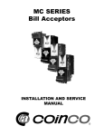
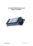
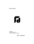
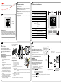
Installation/Configuration Instructions 2 3 Warnings, Cautions, and Notices Specifications and Overall Dimensions Warnings, cautions, and notices are provided in appropriate places throughout this document: WARNING: Indicates a potentially hazardous situation which, if not avoided, could result in death or serious injury. Programmable Touch Screen Thermostat CAUTION: Indicates a potentially hazardous situation which, if not Category avoided, may result in minor or moderate injury. It may also be used to alert against unsafe practices. 1 Input power: NOTICE: Indicates a situation that may result in equipment or propertydamage only accidents. Ordering Numbers: X13511538010, BAYSTAT152A, THT02775 Wire size: Output terminal ratings: Display type: Illustration shows a typical Home screen display. System modes: Fan modes: Operating Temperature Range: Temperature display range: SAFETY WARNING Only qualified personnel should install and service the equipment. The installation, starting up, and servicing of heating, ventilating, and air-conditioning equipment can be hazardous and requires specific knowledge and training. Improperly installed, adjusted or altered equipment by an unqualified person could result in death or serious injury. When working on the equipment, observe all precautions in the literature and on the tags, stickers, and labels that are attached to the equipment. Temperature setpoint range: Humidity display range: Humidity setpoint range: July 2011 © 2011 Trane. All rights reserved. NOTICE 18 to 22 AWG 1A resistive load @ 30Vac LCD/Touch • • • • • Heat Cool Auto Off Emergency Heat 4.65 in (118 mm) • On • Auto 32°F to 122°F (0°C to 50°C) 0.3 in (8 mm) -45°F to 199°F (-42.8°C to 92.8°C) • Heat Setpoint: 40°F to 90°F (4.0°C to 32°C) • Cool Setpoint: 50°F to 99°F (10°C to 37°C) 0% to 99% (1% steps) 30% to 80% (1% steps) Configuration Push cover thumb tab to release cover from backplate. NOTICE Configuration Button Adverse Control System Behavior! Disconnect all electric power, including remote disconnects before servicing. Follow proper lockout/tagout procedures to ensure the power cannot be inadvertently energized. Failure to disconnect power before servicing could result in death or serious injury. Improper configuration setup could cause unwanted, possibly adverse control system behavior. Be sure to configure the thermostat according to your system type. NOTICE Save and move to the next higher or previous lower Option Number To change the installation configuration: 1. Apply electrical power to the thermostat. 2. Determine the configuration options and then write down the selections or other notes on the table in Panel 6. 3. To activate Configuration Option Setup mode: Equipment Damage! WARNING Live Electrical Components! R Security Screw Rc NOTE: If the security screw is installed, remove it before attempting to remove the cover. R Rc (O/B)W Y G C C R Rc (O/B)W Y Dh G S2 Hp Hs C Option Value Option Number Hs Hp S2 a. Remove the thermostat cover. S1 A Y2 (W1) W2 24Vac heating Important: Terminal shipped with jumper connected. Remove jumper if the heat/cool 24 Vac power supplies are separate. 24Vac cooling Important: Terminal shipped with jumper connected. Remove jumper if the heat/cool 24 Vac power supplies are separate. (Changeover valve)(b) Heat relay Stage 1 compressor control relay Fan relay Common (a) Label order above is how they appear on the thermostat terminal block. (b) Text in parentheses indicates that it applies to heat pump systems. The circuit board is energized. Have a qualified licensed electrician or other individual who has been properly trained in handling live electrical components perform this step. Failure to follow all electrical safety precautions when exposed to live electrical components could result in death or serious injury. Increment or Decrement the Option Value Dh S1 Dehumidify relay External humidity sensor input External humidity sensor power External temperature sensor External temperature sensor Economizer relay Stage 2 compressor control relay (Emergency heat relay)(b) Second stage heat relay A Dh(a) Hs Hp S2 S1 A Y2 (W1)W2 W2 Y2 8-pin Connector G Y W Terminal Block Identification 6-pin Connector To mount the backplate: 1. Shut off the power to all HVAC equipment. If the security screw is used, remove it. Refer to the illustration. 2. Push the cover thumb tab to release the cover from the backplate as shown. 3. Route the wires through the opening in the backplate. Wires should be marked to ensure proper connection to terminals. 4. If mounting the backplate directly to a wall surface, hold the backplate against the surface and then level and mark the fastener locations. 5. Secure the backplate using appropriate fasteners. The thermostat should be mounted level and plumb for best air movement through the thermostat enclosure. 6. Locate the terminal blocks from the packaging (new installation) or remove from pin header (existing installation). 7. Connect the wires to the terminal blocks and then push the terminal blocks onto the circuit board pins. 8. Push excess wire through the hole in the wall cavity or into the junction box. Do not coil excess wire between the thermostat and the backplate. 24Vac, 50Hz or 60Hz (18Vac to 32Vac) Note: Frequency is selected using Configuration Option 0190. 1.30 in (33 mm) 5 Hazardous Voltage! Applying excessive voltage to the thermostat will permanently damage it. 5.90 in (150 mm) X39641190-01A 4 Installation Specifications/Descriptions b. Press and hold the Configuration button for 3 seconds. The configuration wrench icon displays along with the configuration option number and value. 4. Press the center or (as shown) to increment or decrement the Option Number. Note: Configuration Mode Display Changing the Option Number with the up/down arrows will also Save the Option Value. In addition, the OK will increment the Option Number and Save the Option Value. 5. Press the right side or (as shown) to increment or decrement the Option Value. 6. Any of the following actions will save settings, exit Configuration Mode, and return to the Home screen: • Push the configuration button momentarily (less than 3 seconds) • Touch and hold for 2 seconds • A 10-minute time out after the last touch in Configuration Mode Save and move to the next higher Option Number or hold for 2 seconds to save and exit Configuration Mode 6 Installation Options Table 1. No. 0100 Table 1. No. Installer configuration setup menu Name Def Temperature indication/Resolution 0 Values/Descriptions • 0= °F, 1 degree resolution • 1= °F, 0.5 degree resolution • 2= °C, 1 degree resolution • 3= °C with 0.5 degree resolution • 4= °C with 0.1 degree resolution • 24= 24-hour clock This setting affects indoor temperature display and setpoint display resolutions. Outdoor temperature display area resolution is always +/1 for both F and C. Refer to Option 0210. Clock Format 12 • 12= 12-hours clock 0120 Year 11 • 11–99 Available year range: 2011–2099. This value is updated to the real time clock after setting. Day of the week is updated automatically. 0121 Month 1 • 1–12 This value is updated to the real time clock after setting. Day of the week is updated automatically. 0122 Day 1 • 1–31 Month dependent; this value is updated to the real time clock after setting. Day of the week is updated automatically. 0125 Daylight Savings 2 • 0= Disabled • 1= US (1987), changeover at 2:00am • 2= US (2007), changeover at 2:00am • • • • Spring Ahead Month Spring Ahead Day Fall Back Month Fall Back Day 0130 System Selection • • • • • 3= Europe, changeover at 1:00am • 4= Manual, changeover at 2:00am • • • • 01-12 01-31 01-12 01-31 8 • 1= 1H/1C (Conv) 1st Stage Heat (W), 1st Stage Comp (Y), Fan (G) • 2= 1H/1C (HP) 1st Stage Comp (Y), Changeover (O/B), Fan (G) • 3= 1H (Conv) 1st Stage Heat (W), without fan • 4= 1H (Conv) 1st Stage Heat (W), Fan (G) • 5= 1C (Conv) 1st Stage Comp (Y), Fan (G) • 6= 2H/1C (HP) 1st Stage Comp (Y), Changeover (O/B), Auxiliary Heat (W1), Fan (G) • 7= 2H/2C (Conv) 1st & 2nd Stage Heat (W,W2), 1st & 2nd Stage Comp (Y,Y2), Fan (G) • 8= 2H/1C (Conv) 1st & 2nd Stage Heat (W,W2), 1st Stage Comp (Y), Fan (G) • 9= 1H/2C (Conv) 1st Stage Heat (W), 1st & 2nd Stage Comp (Y,Y2), Fan (G) • 10= 2H/2C (HP) 1st & 2nd Stage Comp (Y,Y2), Changeover (O/B), Fan (G) • 11= 3H/2C (HP) 1st & 2nd Stage Comp (Y,Y2), Changeover (O/B), Auxiliary Heat (W1), Fan (G) Schedule Options 1 0=Non-programmable 1= Programmable 0150 TOD/Economizer Output (Terminal A) 0 • 0= Unused • 1= TOD energizes terminal A during occupied period, not during unoccupied period. • 2= Economizer energizes terminal A during a call for cool. 0151 Heat Fan Operation 0 0= System controls fan 1= Thermostat controls fan 0153 Reversing Value O/B 0 0= O/B ON when call for cool 1= O/B ON when call for heat 0160 Cycles Per Hour (CPH) [First Stage Compressor] 3 1–5 0161 CPH (Second Stage Compressor) 3 1–5 0162 CPH (First Stage Conventional Heat) 5 1–10 0= Active Control 0206 Internal Humidity Offset Adjustment 0 -9% to 9% in 1% increments 0207 External Humidity Offset Adjustment 0 -9% to 9% in 1% increments 0210 Temperature Sensor Selection 0 • 0= Internal sensor only (10k) • 1= Internal sensor for H/C control (outdoor for display only) [10k] • 2= internal sensor for H/C control (outdoor for Compr/Aux lockout control([10k] • 3= Remote indoor sensor for H/C control (10k) • 4= Use average temperature = (local+S1/S2)/2 for H/C control. 0164 CPH for Auxiliary Heat 9 1–10 • • • • 0= None 15= 15°F (–9.5°C) 20= 20°F (–6.5°C) 25= 25°F (–4.0°C) Allows adjustment of the internal relative humidity reading to account for accuracy, tolerance, and potential drift. FW should use the adjusted value for display and humidity control. Allows adjustment of the external relative humidity reading to account for accuracy, tolerance, and potential drift. FW should use the adjusted value for display and humidity control. 30= 35= 40= 45= 30°F 35°F 40°F 45°F (–1.0°C) (1.5°C) (4.5°C) (7.0°C) 0165 CPH for Emergency Heat 9 1–10 0170 Continuous Backlight 0 0= Backlight ON time is limited 1= Backlight ON continuously 0180 Changeover 1 0= Manual 1= Auto (1°C) (1.5°C) (2.0°C) (2.5°C) • • • • 6= 7= 8= 9= 6°F 7°F 8°F 9°F (3.0°C) (3.5°C) (4.0°C) (4.5°C) 0182 Minimum Compressor Off Time 5 • 0= 0 minutes • 1= 1 minute • 2= 2 minutes • 3= 3 minutes • 4= 4 minutes • 5= 5 minutes 0190 Power Supply Frequency 0 0= 60 Hz 1= 50 Hz 0200 Dehumidify Sensor Selection 1 • 0= Humidity display and function is disabled • 1= Internal humidity sensor enabled 2= External humidity sensor enable Only for systems with cool stage or heat pump. Refer to Option 0130. This setting will extend the compressor OFF time beyond any other delays that are incorporated into the Heat/Cool software algorithm. Only for heat pump systems with more heat stages than cool stages and remote outdoor control sensor. Refer to 0130 and 0210. Note: A 5°F (2.5°C) deadband between heat pump and auxiliary lockout will be enforced. • • • • 0221 Heat Pump Auxiliary Lockout Point 0 • 0= None • 40= 40°F (4.5°C) • 45= 45°F (7.0°C) • 50= 50°F (10.0°C) • 55= 55°F (13.0°C) • 60= 60°F (15.5°C) 0230 Temporary Override Duration Limit 3 • 0= zero hours • 1= one hour • 2= two hours • 3= three hours • 4= four hours 0231 Starting Default Number of Periods 2 2= two periods 4= four periods 0232 Starting Default Period Occ/Unocc Definitions 4 If option #0231 is set to 2 Day—Night • 0= UnOcc—UnOcc • 1= UnOcc—Occ • 2= UnOcc—UnOcc • 3= UnOcc—Occ • 4= Occ—UnOcc • 5= Occ—Occ • 6= Occ—UnOcc • 7= Occ—Occ • 8= UnOcc—UnOcc • 9= UnOcc—Occ • 10= UnOcc—UnOcc • 11= UnOcc—Occ • 12= Occ—UnOcc • 13= Occ—Occ • 14= Occ—UnOcc • 15= Occ—Occ If option #0231 is set to 4 Morn—Day—Evening—Night • 0= UnOcc—UnOcc—UnOcc—Unocc • 1= UnOcc—UnOcc—Unocc—Occ • 2= UnOcc—UnOcc—Occ—UnOcc • 3= UnOcc—Unocc—Occ—Occ • 4= UnOcc—Occ—UnOcc—UnOcc • 5= UnOcc—Occ—UnOcc—Occ • 6= UnOcc—Occ—Occ—UnOcc • 7= UnOcc—Occ—Occ—Occ • 8= Occ—UnOcc—UnOcc—UnOcc • 9= Occ—UnOcc—UnOcc—Occ • 10= Occ—UnOcc—Occ—UnOcc • 11= Occ—UnOcc—Occ—Occ • 12= Occ—Occ—UnOcc—UnOcc • 13= Occ—Occ—UnOcc—Occ • 14= Occ—Occ—Occ—UnOcc • 15= Occ—Occ—Occ—Occ 0233 Days Options for Scheduling Mode 3 • 0= 1 day; Mo-Su all days share the same schedule • 1= 5+1+1 days; Mo-Fr share a schedule. Sa and Su each have an independent schedule • 2= 5+2 days; Mo-Fr share a schedule. Sa-Su share a schedule. • 3= 7 days; Each day has an independent schedule 0240 Heat Temperature Range 90 40–90; 40°F to 90°F 4–32; 4°C to 32°C 0241 Cool Temperature Range 50 50–99; 50°F to 99°F 10–37; 10°C to 37°C 0260 Temperature Display Offset 0 • –3= –3°F (–1.5°C) • –2= –2°F (–1.0°C) • –1= –1°F (–0.5°C) • 0= None • 1= 1°F (0.5°C) • 2= 2°F (1.0°C) • 3= 3°F (1.5°C) 0270 Extended Fan-on Time Heat 0 0= Off 90= ninety seconds This option is not available if option 0151=0 or if the system is cool only. Refer to Option 0130. 0271 Extended Fan-on Time Cool 0 0= Off 40= forty seconds This option is not available for systems with heat only. Refer to Option 0130. 0275 Filter Change Indicator 1 • 0= OFF • 1= 30 days • 3= 90 days • 4= 120 days • 6= 180 days • 12= 365 days 0300 Restore Factory Defaults 0 0= No 1= Yes Only shown for 2H/1C HP or 3H/2C HP systems. Refer to Option 0130. Only applies to auto or manual changeover systems. Refer to Option 0180. For setting 1, 2, or 4; if either temperature sensor is out of range, then the E0 error code will display. 0 Only shown for heat pump systems. Only for systems with both heat and cool stages. Refer to Option 0130. Setting 2 applies only to HP systems and is disabled on all conventional systems. Heat Pump Compressor Lockout Point Only shown for 2H/1C HP or 3H/2C HP systems. Refer to Option 0130. 2°F 3°F 4°F 5°F 1= Passive Control Active control toggles Dh output terminal On and Off as specified by the dehumidify algorithm and is used with a device having its own dehumidification equipment. Passive control runs cool mode for up to 1 extra minute whenever there is a call for cool and dehumidification. 0220 Only shown for conventional system with heat stages and fan capability. For heat pump, the fan relay operates with thermostat control. Only for conventional systems with two stages of conventional heat. 1–10 2= 3= 4= 5= 0 TOD is not available in Non-programmable Mode (refer to Option 0140). Only for conventional systems with heat stages. Refer to Option 0130. Selection in this stage changes default CPH of 2nd stage heat. 9 • • • • Notes Dehumidification Control Only for systems with 2-cool or HP stages. Refer to Option 0130. CPH (Second Stage Conventional Heat) 3 Values/Descriptions 0205 Only for systems with cool or HP stage. Refer to 0130. Selection in this stage changes 2nd stage cool default CPH. 0163 Deadband Def Options available only if 0125 is set to 4. 03 01 11 01 0140 0181 Name Notes 0110 0126 0127 0128 0129 Installer configuration setup menu (continued) Only for heat pump systems with more heat stages than cool stages and remote outdoor control sensor. Refer to 0130 and 0210. Note: A 5°F (2.5°C) deadband between heat pump and compressor lockout will be enforced. Used for temporary override (TOV) starting duration time. Setting of zero does not disable TOV. Provides a starting default number of periods for all days of the week. Occupancy setting can be changed during scheduling for each period/day. Any value toggle of this option (0233) will reset the schedule to the default values of Options 0231 and 0232. In addition, it will return the schedule to default values. Only for systems with heat stage. Refer to Option 0130. Only for systems with cool stage. Refer to Option 0130. Only applies to control temperature and display temperature for internal and indoor remote sensor. Does not apply to outdoor temperature for display. Filter change disabled in OFF. Timer values start on first power up or reset of an active filter icon. No= No action; Yes= Resets all parameters to default except calendar/daylight savings time/system selection. Power supply input is 24 Vac nominal at either 60 Hz or 50 Hz. For external humidity control, a 4–20 mA humidity sensor should be connected to the Hp and Hs terminals to avoid error code E1. Trane optimizes the performance of homes and buildings around the world. A business of Ingersoll Rand, the leader in creating and sustaining safe, comfortable and energy efficient environments, Trane offers a broad portfolio of advanced controls and HVAC systems, comprehensive building services, and parts. For more information, visit www.Trane.com. © 2011 Trane. All rights reserved. X39641190-01A 28 July 2011 NEW