1
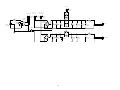
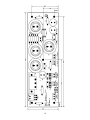
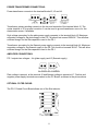
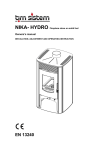
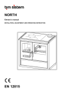
PS-1
Universal Power Supply Board
User’s Manual
500-0002MR2
http://audio.engineeringvista.com
Rev. 2
Dear Customer
We at ENG Vista want to take this opportunity to thank you for purchasing the PS-1 Universal
Power Supply Board. The people that stand behind your Power Supply draw on more than a
decade of professional electronics design and manufacturing experience. We are committed to
providing our customers with the high quality equipment at an affordable price. We have achieved
this goal through modern design, quality parts, expert components sourcing and efficient
manufacturing.
Before using this power supply, please take the time to carefully read and understand the safety
instructions and operating procedures. Becoming familiar with all details about your unit will
ensure safe usage and reliable operation. Take special care when operating with high voltages
and making adjustments.
The effort you invest now will be well rewarded as the time goes by.
THANK YOU!
ENG Vista, Inc.
YOUR SAFETY IS VERY IMPORTANT TO US. PLEASE READ CAREFULLY THE
FOLLOWING NOTES AND SAFETY PRECAUTIONS. THANK YOU.
This kit is not intended for beginners. It requires familiarity with safe
procedures for tests, measurements and modifications of high voltage
equipment.
Exercise extreme caution when working with high voltages and always unplug
the power before making any changes or adjustments.
NOTE: Please make sure to check our website at http://audio.engineeringvista.com for updates,
test results and latest news. On our website you can also order spare parts. Feel free to contact
us with any questions or comments. We are looking forward to hearing from you.
2
SAFETY PRECAUTIONS
IMPORTANT SAFEGUARDS
PLEASE READ CAREFULLY ALL THE FOLLOWING
IMPORTANT SAFEGUARDS THAT ARE APPLICABLE
TO YOUR EQUIPMENT
SAFETY
1.
2.
3.
4.
5.
Read the User’s Manual and refer to it frequently during your experimenting.
Retain the User’s Manual for future reference.
All warnings should be strictly adhered to.
Follow instructions to the last detail.
This product should be operated using only the type of power source indicated in this
manual.
6. Always use an electrical outlet that is grounded. If you do not know whether the outlet is
grounded, consult your electrician or local power company.
7. For continued protection against fire hazard, replace fuses with the same type and rating of
the fuses specified. When changing fuses, completely remove power from the circuit.
8. Power supply cords and all connecting cables or wires should be routed so that they are
not likely to be walked on or pinched. Pay particular attention to cords and cables at plugs,
receptacles and terminal blocks. Always use wires with adequate ratings and safety
certifications (CE, UL, etc.)
9. During operation the tubes get very hot. Do not touch the tubes since this may result in a
severe burn. Allow several minutes after removing power for tubes to cool down before
touching them.
10. Turn off the unit as soon as you stop actively using it. Unplug the power supply from the
wall during a lightning storm or when the product is to be left unattended and unused for
longer periods of time.
11. Do not use this product near water or in wet areas. Damp basements should be avoided.
12. The product should be placed away from heat sources such as radiators, heaters, stoves
or other appliances that produce heat. Also avoid putting the unit in the direct rays of the
Sun.
13. Proper ventilation is crucial for safe and reliable operation. Never place anything on top of
your amplifier that could obstruct airflow and cause the parts to overheat and damage the
amplifier. Do not place your amplifier in a rack or bookcase unless proper ventilation is
provided.
14. Care should be taken to prevent objects from falling and liquids from spilling into the unit.
Do not subject the unit to excessive smoke, dust, vibration or shock.
15. During experimenting, make sure that all jumpers are properly seated in the correct
position, that there are no foreign objects or solder bridges.
16. Always wear protective glasses and exercise caution when powering unit after any change
is made. If possible, gradually rise input voltage and look for any abnormalities – smell or
smoke, tubes overheating (excessive glow), etc.
3
17. Unplug this product from the wall outlet before making any changes. Wait until tubes have
cooled down.
18. When using replacement parts, be sure to use parts with sufficient voltage and power
rating and adequate current carrying capability.
19. Should it become necessary to replace your tubes, remove the AC power plug from the
wall and allow thirty minutes for the high voltage capacitors to discharge.
20. If you have any questions regarding safe and reliable operation of your amplifier, please
email us at [email protected]
4
GETTING STARTED
The PS-1 Power Supply kit was designed to provide you with a universal power supply suitable for
tube equipment (amplifiers, preamplifiers, etc.) and other equipment requiring clean filtered DC
power.
The PS-1 is built on a two sided printed circuit board (PCB) and has two separate outputs for
powering two separate DC loads:
1. Output voltage of up to 400VDC and 500mA, for anode power supply;
2. Output voltage of up to 40V and 2Amp, for heaters.
The printed cisrcuit board will accept many standard leaded (lead spacing 10mm) and snap-in
capacitors. For higher power amplifiers this will enable adding extra filtering. The filte employed ic
a C-R-C and it is very easy to modify it to a C-L-C if the use of a filter inductor is desired. Please
refer to the Connections section for detailed explanation.
If you bought an assembled kit rest assured that all power supplies go through rigorous testing
and extended burn-in before being shipped, so you are guaranteed to receive high quality
product.
The PS-1 kit does not include power transformer, unless it is specifically listed that it does. Power
transformers are sold separately.
With our power transformer 250-0002, the PS-1 will generate anode (plate) voltage of 220-250V
and maximum of 200mA, and heater voltage of 31-33V and maximum of 0.7A output current.
5
ASSEMBLING THE KIT
If you purchased an unassembled kit, you will have all the parts, including printed circuit board.
Parts are in marked bags, with reference numbers and value written on a bag. Reference
numbers are the ones printed on the PCB, so locating parts positions should be very easy. PCB
layout printout is also part of this document and you can use it to locate parts. Power transformer
is purchased separately, and not included in the kit.
First step is to review all the materials received, compare to the part list and prepare all tools and
a well lit work area. Tools that you need are very basic – soldering iron, tweezers or flat pliers, and
cutters. You will also need solder wire and a digital multimeter.
- Start assembly with jumpers, grounding negative end of plate and heater power supply. In some
specific (and very rare) situations it is not required to ground the power supplyand you will not
install the jumpers.
- Follow with resistors and fuses, keeping in mind that both, resistors and fuses should be slightly
elevated off the PCB (1/32” is sufficient). Main reason is that power resistors get warm and this
will help air circulation and prevent overheating. Also, some resistors have circuit connections
underneath and there is a possibility of malfunction if the resistor body touches exposed trace.
This is not very likely, since the PCB connections are protected by a solder mask and resistors
have durable coating. However, this could be a matter of safety and, also, troubleshooting of such
problems is really difficult, so it is better to spend some extra time up front to come up with great
assembly.
- Next step is assembly of all capacitors. Make sure to follow polarity directions for electrolytic
capacitors. All electrolytics have markings designating leads to be connected to the negative
voltage. PS-1 printed circuit board has a plus sign for the positive terminal of an electrolytic
capacitor. Positive terminal on the PCB also has a square pad around the hole, for easier
identification on the bottom of the board.
- After capacitors are installed you can proceed with connectors.
Once everything is installed, take a short break and then come back and carefully inspect your
work. Check component locations and proper orientation of electrolytic capacitors. Inspect all
solder joints and make sure there are no solder bridges or splashes on the board. All joints should
look clean and shiny. If you are not sure that a solder joint look right, touch it with a hot soldering
iron again, until it looks right. Cold solder joints may create problems few hours (days, months)
down the road and are extremely difficult to troubleshoot.
Then, connect the power transformer and proceed with slowly powering the unit. Variable
autotransformer (a.k.a. variac) is a very helpful tool during this initial phase.
Measure voltage on the primary and all secondaries, as well as output voltages for plates and
filaments. Keep in mind that during this test there is no load and measured voltages may be up to
25% higher than expected. Transformer secondary voltages and output DC voltages are specified
for the maximum load and will be significantly lower once you connect your equipment.
After the test is done, shut down the power, wait 5 minutes for capacitors to discharge and then
connect your equipment and repeat the process. After reaching the steady state, your voltages
should be very close to the nominal ones.
6
CONNECTIONS
ELECTRICAL SCHEMATICS:
The complete electrical schematics with component values is given to assist you in your
experiments. Please note that the schematics is considered a copyrighted work and a trade
secret. However, as a purchaser of our product you are granted a license for unlimited
modifications. The only thing we ask for is that this schematics is not reprinted for public use or
commercially used without getting appropriate license from ENG Vista, Inc.
Depending on your particular kit, some of the parts may have different values or not be used.
7
CHOKE
1
2
J5
XFMR_SEC_1
XFMR_SEC_2
PLATE
FILAMENT
R7
1k/2W
206-0003
3
+ 1
1
2
C1
*100n/400V*
100-0012
2
1
F2
206-0003
R4
1k/2W
SW1
C2
47u/450V
100-0010
C3
47u/450V
100-0010
206-0003
R5
1k/2W
500mA
170-0001
C4
47u/450V
100-0010
C5
120u/450V
100-0011
R6
270k/2W
206-0004
J6
2
1
C6
100n/400V
100-0012
PLATE
CONN PCB 2
160-0004
206-0003
3
160-0006
IEC CONN
J1
3
2
D1
2KBP10M
220-0001
4 -
206-0003
R3
1k/2W
R8
0R
R10
0R/2W
R9
0R
206-NONE
D2
2KBP10M
220-0001
4 -
2
1
3A
170-0002
180-0001
SW DPDT
6
5
4
CONN PCB 2
160-0004
+ 1
R13
2k7/2W
206-0005
C7
*100n/400V*
100-0012
C8
1000u/50V
100-0008
3
F1
CONN PCB 2
160-0004
206-0003
R2
1k/2W
J4
J3
1
2
1
2
3
J2
CONN PCB 3
160-0003
R1
1k/2W
2
XFMR_PRI
CONN PCB 2
160-0004
8
F3
R11
0R/2W
3A
170-0002
206-NONE
D3
LED
220-0002
C9
1000u/50V
100-0008
C10
1000u/50V
100-0008
C11
*100n/400V*
100-0012
J7
2
1
FILAMENT
CONN PCB 2
160-0004
BOARD LAYOUT AND DIMENSIONS:
The following Figure shows the component layout, dimensions of the board (in mils –
1mil=0.001inch), mounting holes and locations of all components. This should help builder with
designing a fitting enclosure. Please always verify dimensions by measuring the actual printed
circuit board.
9
10
POWER TRANSFORMER CONNECTIONS:
Power transformer connects to the terminal blocks J2, J3 and J4.
Transformer primary winding connects to the two end terminals of the terminal block J2. The
center terminal of J2 is ground conection. It can be used to ground transformer core or for the
electrostatic screen, if available.
High voltage secondary for the plate power supply connects to the terminal block J3. Maximum
secondary voltage for the plate supply in the PS-1 kit should not exceed 260VAC. This will allow
sufficient margin for the filter capacitors used in the PS-1.
Transformer secondary for the filament power supply connects to the terminal block J4. Maximum
secondary voltage for the filament supply in the PS-1 kit should not exceed 32VAC. This will allow
sufficient margin for the filter capacitors used in the PS-1.
AMPLIFIER CONNECTIONS:
PS-1 outputs two voltages – Va (plate supply) and Vf (filament supply).
Plate voltage is present at the terminal J6 and filament voltage is present at J7. Positive and
negative power supply terminals are marked on the PC Board, as shown in the picture above.
OPTIONAL FILTER CHOKE:
The PS-1 Printed Circuit Board allows use of the filter inductor.
11
Resistors R1 to R5 should be removed from the PCB and external choke can be connected to the
terminal J5. This modification transforms the original C-R-C filter into the C-L-C and is best suited
for higher power applications.
FINAL WORDS
Once again, thank you for your purchase. We hope that the PS-1 will give you hours and hours of
fun and have you experience a multitude of different qualities of the “tube sound”. Robust design
should provide you with years of safe and reliable use.
Finally, we want to remind you once again to take extreme caution while working with high
voltages. If you are not thoroughly familiar with the safety procedures, feel free to enlist help of a
relative or friend. There are many very knowledgeable people in this field and they all share
passion for spreading the art and science of high quality sound reproduction.
Copyright, ENG Vista, Inc. 2006
12
PARTS LIST
Parts with asterisks in the VALUE column are not used. They have the place on the PCB, so you
can add them if you feel that they will improve the sound of your amplifier.
Item
1
2
3
4
5
6
7
8
9
10
11
12
13
14
15
16
17
18
19
Qty
Reference
1 R13
3 R8,R9,R11
1 R6
6 R1,R2,R3,R4,R5,R7
1 J1
5 J3,J4,J5,J6, J7
1 J2
1 F2
2 F1,F3
1 D3
2 D2,D1
3 C8,C9,C10
1 C6
3 C1, C7, C11
4 C2,C3,C4
1 C5
1 SW1
1 PCB
1 User's
EPN
Value
206-0005
206-NONE
206-0004
206-0003
160-0006
160-0004
160-0003
170-0001
170-0002
220-0002
220-0001
100-0008
100-0012
100-0012
100-0010
100-0011
180-0001
500-0002
500-
2k7/2W
0R
270k/2W
1k/2W
IEC CONN
CONN PCB 2
CONN PCB 3
500mA
3A
LED
2KBP10M
1000u/50V
100nF/400V
*100nF/400V
47uF/450V
120uF/450V
SW DPDT
13