1
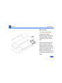
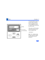
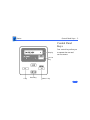
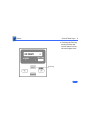
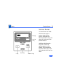
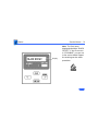
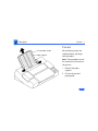
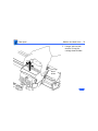
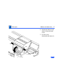
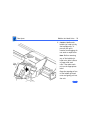
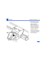
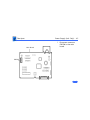
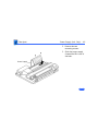
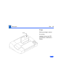
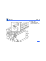
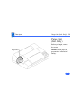
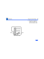
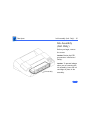
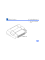
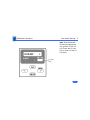
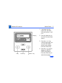
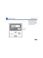
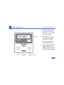
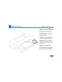
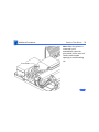
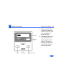
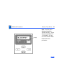
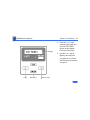
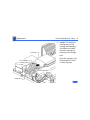
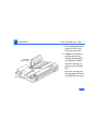
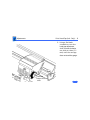
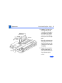
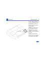
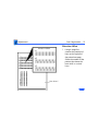
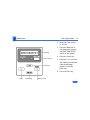
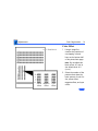
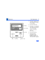
K Service Source
Apple Color Printer
K Service Source
Basics
Apple Color Printer
Basics
Overview - 1
Overview
Control
Panel
The Apple Color Printer
control panel signals
printer errors by means of
status messages, an alarm
indicator light, and a beep
tone.
Using a set of control keys,
you can perform various
service functions from the
control panel. There are two
modes of operation from the
panel: user and service.
Different levels and types of
menus are accessible in each
mode.
Basics
Overview - 2
Display
On Line Key
On Line Indicator
To access either the user or
service menus, you must
turn the printer off-line.
You can toggle the printer
on- and off-line by pressing
the On Line key.
The printer is off-line when
the on line indicator is off
and the display reads
“00 READY.”
Note: The * indicates that
the print heads are capped
and the printer may be
turned off.
Basics
Control Panel Keys - 3
Control Panel
Keys
Display
On Line
Key
< Key
Enter Key
Menu/> Key
Four control keys allow you
to operate the user and
service menus.
Basics
Control Panel Keys - 4
• Pressing the Exit key
moves you from the
current menu level to
the next higher level.
Exit Key
Basics
Control Panel Keys - 5
• Pressing the Enter
key moves you from
the current menu
level to the next
lower level. If you are
at the lowest menu
level, pressing the
Enter key executes
the menu item that is
currently displayed.
Enter Key
Basics
Control Panel Keys - 6
• Pressing the > or <
key changes the menu
to the next choice at
the same level and
changes the value of
any parameter
displayed.
< Key
Menu/> Key
Basics
User Menus - 7
User Menus
Display
On Line
Key
< Key
Enter Key
Menu/> Key
To enter the user mode and
access the user menus,
switch on the printer and set
it to off-line (press the On
Line key so that the on line
indicator turns off).
Press the Menu key once to
see the first menu displayed.
Then use the > or < key to
move between the menus
and choices.
Press the Enter key to
execute a selection.
Basics
User Menus - 8
The following selections are available in the user menus:
PRINTING MODE
• MODE-A
Prints plain paper, envelopes, or coated paper
• MODE-B
Prints transparencies
• MODE-C
Prints blacks twice as dark
• MODE-D
Reduces bleeding on graphics with plain paper; increases
printing time considerably
• MODE-E
Prints high-speed drafts
Basics
User Menus - 9
CLEANING
• CLEANING-A
Cleaning A clears print head of clogged ink nozzles.
• CLEANING-B
If Cleaning A does not work after 2–3 times, use Cleaning
B. Cleaning B uses more time and ink
(1.5 min. and 2 g of ink).
SET PARAMETER
The Set Parameter menu controls settings for parallel
interface. Do not change any of these settings.
Basics
User Menus - 10
TEST PRINT
• TEST PRINT-A
Gives current status of printer (ROM version, interface,
etc.) as well as a color grid
• NOZZLE CHECK
Gives test pattern to check print head
DUMP MODE
• DUMP OFF (default mode)
• DUMP ON
INTERFACE SELECT
• SCSI (default mode)
Use Enter key to set SCSI ID number.
• PARALLEL
Basics
User Menus - 11
COUNTRY CODE
•
•
•
•
•
•
•
•
•
•
•
•
ENGLISH (default)
FINNISH
FRENCH
GERMAN
ITALIAN
JAPANESE
NORWEGIAN
PORTUGUESE
SPANISH
SWEDISH
DANISH
DUTCH
NVRAM INITIALIZE
• INIT. NO (default)
• INIT. YES
Basics
User Menus - 12
MEDIA SELECT
• NORMAL PAPER (default)
• ENVELOPE/THICK
Basics
Service Menus - 13
Service Menus
Display
On Line
Key
< Key
Enter Key
Menu/> Key
To enter the service mode
and access the service
menus, switch off the
printer, hold down the
Menu key and the < key at the
same time, and switch the
printer back on.
Hold down the Menu and <
keys until a series of
squares appears on the
display. Then release the
keys, hold down the On Line
key, and press the Enter key
twice.
Basics
Service Menus - 14
Display
Note: The first menu
displayed should be “BLACK
OFFSET.” If the first menu
is “CLEANING,” you are not
in the service mode. Repeat
the entering service mode
procedure.
Basics
Service Menus - 15
The following selections are available in the service menus:
BLACK OFFSET
Sets value for Black registration
CYAN OFFSET
Sets value for Cyan registration
MAGENTA OFFSET
Sets value for Magenta registration
YELLOW OFFSET
Sets value for Yellow registration
Basics
Service Menus - 16
DIRECTION OFFSET
Sets the printing position for printing in both directions
TEST PRINT
• TEST PRINT-A
Bubble-jet head jet check pattern
• TEST PRINT-B
Bubble-jet head/main unit precision check pattern 1
• TEST PRINT-C
Printing position setting pattern
• TEST PRINT-D
Bubble-jet head/main unit precision check pattern 2
• HEAT RUN
Printer mechanism drive function for factory inspection
Basics
Service Menus - 17
CLEANING
• CLEANING-A
Clears print head of clogged ink nozzles
• CLEANING-B
Checks the ink passage pressure
• CLEANING-C
Fills ink passage in the ink supply system
• CLEANING-D
Flushes ink supply system
Basics
Service Menus - 18
CENTER HEAD
Moves the carriage to the center of the printer to allow
replacement of the bubble-jet head unit
When you press the Enter key, the carriage moves (while
the beeper sounds) and stays at the center of the printer for
5 seconds. The carriage then returns to its home position. To
exit this mode, switch the power off.
Basics
Block Diagram - 19
Block Diagram
Basics
Wiring Diagram - 20
Wiring Diagram
CNEXT
CNPOW
Basics
Wiring Diagram - 21
CNMOT
Basics
Wiring Diagram - 22
CNMEC
Basics
Wiring Diagram - 23
CNPGM
CNPG
CNINK
CNID
Basics
Wiring Diagram - 24
CNPE
CNPAN
Basics
Wiring Diagram - 25
CNCAR1
Basics
Wiring Diagram - 26
CNCAR2
Basics
Wiring Diagram - 27
CNCA1
Basics
Wiring Diagram - 28
CNCA2
Basics
Wiring Diagram - 29
CNY
Basics
Wiring Diagram - 30
CNM
Basics
Wiring Diagram - 31
CNC
Basics
Wiring Diagram - 32
CNK
Basics
Wiring Diagram - 33
CNPW
K Service Source
Specifications
Apple Color Printer
Specifications
Characteristics - 1
Characteristics
Print Methods
Throughput
Serial bubble jet ink-on-demand
170 cps (10 cpi)
300 cps (10 cpi)
6.120 dots/sec.
text/standard speed mode
text/high-speed mode
bit image
Print Head
1 x 64 nozzles for each color
Print Head Life
Approximately 100 million characters (MODE-A)
Input Buffer
7 KB
Specifications
Graphics - 2
Graphics
Resolution
360 dpi (best mode)
Specifications
Paper Handling - 3
Paper Handling
Paper
Cut Sheets
Coated (recommended)
LDG, LTR, LGL, A3, B4, A4
Width: 7.9 in. to 11.7 in. (210 to 297 mm)
Length: 7.9 in. to 17.0 in. (210 to 432 mm)
Weight: 16 to 24 lbs.
Capacity: 100 sheets (A4, LTR)
50 sheets (B4, A3, LGL, LDG)
Envelopes
Commercial Number 10 size only (4.1 in. x 9.5 in)
Capacity: 5 envelopes
Transparencies
Coated transparencies, most inkjet transparencies
Specifications
Ink Cartridges - 4
Ink Cartridges
Type
Color ink cartridges (four available)
Ink Color
Black, Cyan, Magenta, Yellow
Ink Amount
Approx. 30 g (per cartridge)
Life
Text: Approx. 700 pages (A4/LTR)
Specifications
Environmental - 5
Environmental
Acoustic Noise Level
Approx. 45 dB (reference level)
Temperature
59°F to 86°F (15°C to 30°C)
Humidity
10% to 80% (no condensation)
Specifications
Electrical - 6
Electrical
Power Source
AC 120V 60Hz 0.36A (U.S./Canada)
Power Consumption
48 W maximum
Specifications
Physical - 7
Physical
Dimensions
Weight
Height: 6.7 inches (169 mm)
Width: 20.5 inches (520 mm)
Depth: 16.0 inches (407 mm)
Approx. 22 lbs (10 kg)
K Service Source
Troubleshooting
Apple Color Printer
Troubleshooting
General/ - 1
General
The Symptom Charts included in this chapter will help you
diagnose specific symptoms related to your product. Because cures
are listed on the charts in the order of most likely solution, try
the first cure first. Verify whether or not the product continues to
exhibit the symptom. If the symptom persists, try the next cure.
(Note: If you have replaced a module, reinstall the original module
before you proceed to the next cure.)
If you are not sure what the problem is, or if the Symptom Charts
do not resolve the problem, refer to the Flowchart for the product
family.
For additional assistance, contact Apple Technical Support.
Troubleshooting
Symptom Charts /Operation - 2
Symptom Charts
Operation
No power
1
2
3
4
Check power cable connections.
Replace power cord.
Replace fuse.
Replace power supply (international repairers only) or
return printer to Apple for service.
Troubleshooting
Does not print
Symptom Charts /Operation - 3
1
2
3
4
5
6
7
8
9
Turn on printer and restart computer. Make sure ON LINE
is displayed.
Press On Line key.
Check interface cable connections.
If error message is displayed, see “Error Messages” in
this chapter.
Check SCSI setting.
Use Apple-approved SCSI cable.
Check that SCSI connections are terminated properly.
Replace printer driver.
Replace SCSI card assembly or return printer to Apple
for service.
Troubleshooting
Symptom Charts /Paper - 4
Paper
Paper sticks together
1
2
3
Remove excess sheets from paper tray.
Use specified media only.
Check that settings in Page Setup menu are correct.
Paper skews
1
2
3
Remove excess sheets from paper tray.
Use specified media only.
Stack paper flush against left side of paper tray and adjust
paper guide.
Check rollers. Clean or replace if necessary (international
repairers only).
4
Paper jams and
printer displays
“13 CHECK PAPER”
error code
Remove paper from tray and press On Line key. If jammed paper
does not eject, carefully remove it by hand.
Troubleshooting
Symptom Charts /Paper - 5
Paper jams during
loading, before
printing
Carefully remove paper by hand.
Paper jams inside
printer
Remove top cover. Pull out paper in direction of paper output.
(Do not pull paper back toward you. Doing so could bend stainless
steel bar that holds paper down.)
Paper jams during
output, after printing
Pull out paper in direction of paper output.
Troubleshooting
Blurring and/or
smudging
Symptom Charts /Paper - 6
1
2
3
4
5
6
Adjust print head position lever all the way down.
Use specified media only.
Set printer to proper printing mode. See “User Menus” in
Basics chapter.
Make sure print head is in correct position. If necessary,
perform the adjustments described in “Print Head Gap” in
the Adjustments chapter (international repairers only).
Perform the “Print Head Cleaning” procedure; see the
Additional Procedures chapter (international repairers
only).
Check print head gap; see “Print Head Gap” in Adjustments
chapter (international repairers only).
Troubleshooting
Symptom Charts /Print Quality - 7
Print Quality
Missing dots and/or
white streaks
1
2
3
4
5
6
Perform “Print Head Cleaning” and “Nozzle Check.”
See Additional Procedures chapter.
Make sure ink cartridges are set firmly.
Use specified media only.
Replace bubble-jet head unit.
Replace carriage board (international repairers only).
Replace logic board (international repairers only).
Troubleshooting
Symptom Charts/Error Messages - 8
Error Messages
00 READY
00 READY
In on-line state, message indicates that printer is ready to accept
data. In off-line state, message indicates that printer is not
experiencing any errors.
*
Print head has been properly capped and printer can be turned off.
00 IGNORE DATA
Message indicates that data has been ignored and discarded. Press
Menu and < keys at same time. Printer will then return to
standard operating mode and message will change to “00 READY.”
01 TEST PRINT
Printer is executing self-test print.
press On Line key.
02 WARMING UP
Printer is warming up. Allow approximately 30 seconds before
printing.
After test print is finished,
Troubleshooting
Symptom Charts/Error Messages - 9
03 RESET
Printer is restoring its setting to power-up status.
08 CLEANING
Printer is cleaning print head.
10 CHECK PAPER
Paper has run out or is inserted improperly. Load paper into
paper feed.
40 SERVICE
1
2
3
4
Check SCSI cable.
Check SCSI terminator.
Replace SCSI card assembly.
Replace logic board (international repairers only) or return
printer to Apple for service.
Troubleshooting
Symptom Charts/Error Messages - 10
50 SERVICE
1
2
3
4
5
6
Check carriage motor.
Remove any obstructions in carriage drive path.
Replace print timing slit (international repairers only).
Replace encoder unit (international repairers only).
Replace carriage board (international repairers only).
Replace logic board (international repairers only) or return
printer to Apple for service.
51 SERVICE
1
2
3
4
5
6
7
Check carriage motor.
Remove any obstructions in carriage drive path.
Replace print timing slit (international repairers only).
Replace encoder unit (international repairers only).
Replace carriage board (international repairers only).
Replace logic board (international repairers only).
Replace purge unit (international repairers only) or return
printer to Apple for service.
Troubleshooting
52-55 SERVICE
Symptom Charts/Error Messages - 11
1
2
3
56-59 SERVICE
1
2
3
Check bubble-jet head unit connection.
Replace bubble-jet head unit.
Error 52 Black bubble-jet head unit
Error 53 Cyan bubble-jet head unit
Error 54 Magenta bubble-jet head unit
Error 55 Yellow bubble-jet head unit
Return printer to Apple for service.
Check bubble-jet head unit connection.
Replace bubble-jet head unit.
Error 56 Black bubble-jet head unit
Error 57 Cyan bubble-jet head unit
Error 58 Magenta bubble-jet head unit
Error 59 Yellow bubble-jet head unit
Return printer to Apple for service.
Troubleshooting
5A-5D SERVICE
Symptom Charts/Error Messages - 12
1
2
5E SERVICE
1
2
3
4
Replace bubble-jet head unit.
Error 5A Black bubble-jet head unit
Error 5B Cyan bubble-jet head unit
Error 5C Magenta bubble-jet head unit
Error 5D Yellow bubble-jet head unit
Return printer to Apple for service.
Unlock carriage lock lever located under printer cover.
Check carriage for binding. Perform “Print Head Gap” in the
Adjustments chapter (international repairers only).
Replace carriage drive motor (international repairers only).
Replace logic board (international repairers only) or return
printer to Apple for service.
Troubleshooting
5F SERVICE
Symptom Charts/Error Messages - 13
1
2
3
4
Unlock carriage lock lever located under printer cover.
Check carriage for binding. If necessary, perform “Print
Head Gap” in the Adjustments chapter (international
repairers only).
Replace carriage drive motor (international repairers only).
Replace logic board (international repairers only) or return
printer to Apple for service.
61 SERVICE
Replace logic board (international repairers only) or return
printer to Apple for service.
61 SERVICE
Replace logic board (international repairers only) or return
printer to Apple for service.
63 SERVICE
Replace logic board (international repairers only) or return
printer to Apple for service.
Troubleshooting
Symptom Charts /Error Messages - 14
65 SERVICE
1
2
3
Replace logic board (international repairers only).
Replace control panel (international repairers only).
Replace ribbon cables (international repairers only) or
return printer to Apple for service.
Note: Printer beeps a number of times while displaying this
error code.
66 SERVICE
Replace logic board (international repairers only) or return
printer to Apple for service.
68 SERVICE
Replace logic board (international repairers only) or return
printer to Apple for service.
72 SERVICE
Replace logic board (international repairers only) or return
printer to Apple for service.
K Service Source
Take Apart
Apple Color Printer
Take Apart
Covers - 1
Covers
Printed Paper Guide
Paper Support
No preliminary steps are
required before you begin
this procedure.
Note: This procedure covers
the removal of all covers on
the printer.
1
2
Remove the paper
support.
Pull up the printed
paper guide.
Take Apart
Covers - 2
3
Front Cover
Pull the front cover
toward you and lift off
the cover.
Take Apart
Covers - 3
4
Printer Cover
Unit
5
Lift off the printer cover
unit.
Carefully place the
printer cover unit with
the inner cover rollers
facing up.
Take Apart
Covers - 4
6
7
Inner Cover Roller
Printer Cover
Unit
Using a small
screwdriver, push out
the two latches.
Pull up and remove the
inner cover roller.
Take Apart
Upper Cover
Covers - 5
8
Loosen the two screws
and lift off the upper
cover.
Take Apart
Covers - 6
9
Press the center of the
ink cartridge cover and
release the coupler.
10 Push down and remove
the ink cartridge cover.
Coupler
Ink Cartridge
Cover
Take Apart
Covers - 7
11 Using a small
screwdriver, push in the
two small latches and
press up the coupler.
Latch
Latch
Coupler
Take Apart
Covers - 8
12 Remove the two rear
cover mounting screws.
13 Lift up the front of the
rear cover.
14 Pull back the rear cover
and remove the cover.
Rear Cover
Take Apart
Control Panel (Intl. Only) - 9
Control Panel
(Intl. Only)
Before you begin, remove
the covers.
Control Panel
Caution: Review the ESD
precautions in Bulletins/
Safety.
Take Apart
Control Panel (Intl. Only) - 10
1
Carriage
Print Heads
Locking Tab
Plate
Purge Unit
2
Lift the plate on the
purge unit.
Push down the locking
tab and move the
carriage out of home
position.
Caution: The print heads
are now uncapped. Do not
leave them uncapped for
more than 12 hours or
they will dry out.
Take Apart
Control Panel (Intl. Only) - 11
3
Control Panel
4
Latch
Push in the latch, lift
the front of the control
panel, and pull it toward
you.
Lay the control panel in
front of the printer.
Take Apart
Control Panel (Intl. Only) - 12
5
Control Panel Base
Latch
Pull the latch and lift up
the control panel base.
Take Apart
Control Panel (Intl. Only) - 13
6
7
Right Connector Card
Control Panel
Connector
Control Panel
Disconnect the control
panel connector from the
right connector card.
Remove the control
panel.
Take Apart
Bubble-Jet Head Units - 14
Bubble-Jet Head
Units
Bubble-Jet
Head Units
Before you begin, remove
the covers.
Caution: Review the ESD
precautions in Bulletins/
Safety.
Caution: Do not get the ink
on your hands or clothes.
Although the ink is water
soluble, it contains dyes that
will stain.
Take Apart
Bubble-Jet Head Units - 15
Carriage
Print Heads
Locking Tab
Plate
Purge Unit
1
2
Caution: To prevent the
print nozzles from
clogging, do not touch or
wipe them.
Lift the plate on the
purge unit.
Push down the locking
tab and move the
carriage out of home
position.
Caution: The print heads
are now uncapped. Do not
leave them uncapped for
more than 12 hours or
they will dry out.
Take Apart
Bubble-Jet Head Units - 16
3
Carriage
Board
Holder
Using a side-to-side
motion, lift up the
carriage board holder.
Take Apart
Bubble-Jet Head Units - 17
4
5
Tab
Tab
Print Head
Cover
Release the tabs on both
sides of the print head
cover.
Pull the cover
downward and remove it.
Take Apart
Bubble-Jet Head Units - 18
6
Bubble-Jet
Head Unit
Top
Edge
Print Nozzles
Caution: Handle each
bubble-jet head unit by
the top edge only. To
prevent the print
nozzles from clogging, do
not touch or wipe them.
Note: Before removing
any of the bubble-jet
head units, label a sheet
of paper with each
color. Then place each
unit on the appropriate
label.
Grasp the top edge of one
of the bubble-jet head
units and gently pull out
the unit.
Take Apart
Bubble-Jet Head Units - 19
7
Bubble-Jet
Head Unit
Top
Edge
Print Nozzles
Repeat for each of the
three remaining units.
Replacement Note:
Before installing a new
bubble-jet head unit,
remove the orange tape
and grey rubber cap
that cover the print
nozzles. Do not shake the
new bubble-jet head or
the ink may leak.
Take Apart
Carriage Assembly (Intl. Only) - 20
Carriage
Assembly
(Intl. Only)
Before you begin, remove
the following:
• Covers
• Control panel
Caution: Review the ESD
precautions in Bulletins/
Safety.
Carriage Assembly
Take Apart
Carriage Assembly (Intl. Only) - 21
1
Carriage
Print Heads
Locking Tab
Plate
Purge Unit
2
Lift the plate on the
purge unit.
Push down the locking
tab and move the
carriage out of home
position.
Caution: The print heads
are now uncapped. Do not
leave them uncapped for
more than 12 hours or
they will dry out.
Take Apart
Carriage Assembly (Intl. Only) - 22
3
CNCA2
CNCA1
Right Connector Card
Disconnect the two cable
connectors CNCA2 and
CNCA1 from the right
connector card.
Take Apart
Carriage Assembly (Intl. Only) - 23
Reservoir Overflow
Connector
Reservoir Supply
Connector
4
Caution: Make sure the
reservoir connectors
are secured. If they are
not, ink could spill into
the printer.
Remove the reservoir
supply and reservoir
overflow connectors and
hook them onto the
carriage assembly.
Take Apart
Carriage Assembly (Intl. Only) - 24
5
6
Ground Screw
Assembly
Carriage
Motor
Connector
Remove the ground
screw.
Disconnect the carriage
motor connector.
Take Apart
Carriage Assembly (Intl. Only) - 25
7
Ink Tubes
Screw
Mounting
Tab
8
Remove the screw and
push in the mounting
tab on one side of the
carriage assembly.
Repeat for other side.
Lift out the carriage
assembly.
Replacement Note: Make
sure the ink tubes are
not caught under the
carriage assembly.
Take Apart
Carriage Board (Intl. Only) - 26
Carriage Board
(Intl. Only)
Before you begin, remove
the covers.
Carriage Board
Caution: Review the ESD
precautions in Bulletins/
Safety.
Take Apart
Carriage Board (Intl. Only) - 27
1
Carriage
Print Heads
Locking Tab
Plate
Purge Unit
2
Lift the plate on the
purge unit.
Push down the locking
tab and move the
carriage out of home
position.
Caution: The print heads
are now uncapped. Do not
leave the heads uncapped
for more than 12 hours
or they will dry out.
Take Apart
Carriage Board (Intl. Only) - 28
3
Carriage
Board
Holder
Using a side-to-side
motion, lift up the
carriage board holder.
Take Apart
Carriage Board (Intl. Only) - 29
4
Carriage Board Cover
Latch
Push in the two latches
and remove the carriage
board cover.
Take Apart
Carriage Board (Intl. Only) - 30
5
CNPW
CNCA1
Carriage Board
Disconnect the following
connectors from the
carriage board:
• CNCA1
• CNCA2
• CNPW
Take Apart
Carriage Board (Intl. Only) - 31
6
Position 2
Carriage Position Lever
Set the carriage position
lever to position 2.
Take Apart
Carriage Board (Intl. Only) - 32
Carriage
Board Holder
7
8
Caution: To avoid
damaging the carriage
position lever, make
sure you do not use
excessive force when
removing the carriage
board holder.
Carefully pull out the
sides of the carriage
board holder.
Lift up and remove the
holder from the
carriage.
Take Apart
Carriage Board (Intl. Only) - 33
9
Carriage Board
Side Catch
Bottom Catch
Carriage Board
Holder
Carefully push apart the
carriage board holder
and slide out the carriage
board.
Replacement Note: Make
sure the board seats in
the bottom and side
catches.
Take Apart
Carriage Drive Motor (Intl. Only) - 34
Carriage Drive
Motor (Intl. Only)
Before you begin, remove
the covers.
Carriage Drive
Motor
Caution: Review the ESD
precautions in Bulletins/
Safety.
Take Apart
Carriage Drive Motor (Intl. Only) - 35
1
Carriage
Print Heads
Locking Tab
Plate
Purge Unit
2
Lift the plate on the
purge unit.
Push down the locking
tab and move the
carriage out of home
position.
Caution: The print heads
are now uncapped. Do not
leave the heads uncapped
for more than 12 hours
or they will dry out.
Take Apart
Carriage Drive Motor (Intl. Only) - 36
3
4
Idler Roller
Bracket
Screw
Belt
Loosen the screw.
Push in the idler roller
bracket and remove the
belt from the carriage
drive motor.
Take Apart
Carriage Drive Motor (Intl. Only) - 37
5
6
7
Mounting Screw
Ground Screw
Carriage
Drive
Motor
Carriage
Motor
Connector
Disconnect the carriage
motor connector.
Remove the mounting and
ground screws.
Remove the carriage
drive motor.
Take Apart
Print Timing Slit (Intl. Only) - 38
Print Timing Slit
(Intl. Only)
Before you begin, remove
the covers.
Print Timing Slit
Caution: Review the ESD
precautions in Bulletins/
Safety.
Take Apart
Print Timing Slit (Intl. Only) - 39
1
Print Timing Slit
Tab
Carefully remove the
print timing slit from
the tab on one side of the
carriage assembly.
Take Apart
Print Timing Slit (Intl. Only) - 40
2
Triangle
3
Carefully remove the
print timing slit from
the tab on the other side
of the carriage assembly.
Remove the print timing
slit from the carriage
assembly.
Replacement Note: Make
sure the triangle on the
print timing slit is
facing up.
Print Timing
Slit
Take Apart
SCSI Card Assembly - 41
SCSI Card
Assembly
SCSI Card
Assembly
Before you begin, remove
the covers.
Caution: Review the ESD
precautions in Bulletins/
Safety.
Take Apart
SCSI Card Assembly - 42
1
SCSI Card
Assembly
Remove the two
mounting screws and
lift off the SCSI card
assembly.
Take Apart
SCSI Card Assembly - 43
2
3
SCSI Card Covers
SCSI Card
Mounting
Screw
Turn over the SCSI card
assembly.
Remove the six mounting
screws and remove the
SCSI card covers.
Take Apart
Power Supply (Intl. Only) - 44
Power Supply
(Intl. Only)
Power Supply
Before you begin, remove
the covers.
Caution: Review the ESD
precautions in Bulletins/
Safety.
Take Apart
Power Supply (Intl. Only) - 45
1
Main Board
CNPOW
Disconnect connector
CNPOW on the main
board.
Take Apart
Power Supply (Intl. Only) - 46
2
3
Power Supply
Remove the two
mounting screws.
Slide the power supply
forward and lift it out of
the base.
Take Apart
Power Supply (Intl. Only) - 47
Replacement Note: Make
sure the tab on the
power supply switch is
correctly seated in the
on/off switch arm.
Power
Supply
Switch
On/Off
Switch
Arm
Take Apart
Fuse - 48
Fuse
Fuse
Before you begin, remove
the covers.
Caution: Review the ESD
precautions in Bulletins/
Safety.
Take Apart
Fuse - 49
1
Cover Plate
Loosen the screw and
move aside the cover
plate.
Take Apart
Fuse - 50
2
Fuse
Using a small
screwdriver or fuse
puller, remove the fuse.
Take Apart
Logic Board (Intl. Only) - 51
Logic Board
(Intl. Only)
Logic Board
Before you begin, remove
the following:
• Covers
• SCSI card assembly
Caution: Review the ESD
precautions in Bulletins/
Safety.
Take Apart
Logic Board (Intl. Only) - 52
1
Main Board
CNCAR2
CNCAR1
CNMEC
Disconnect the following
connectors from the
main board:
• CNCAR2
• CNCAR1
• CNMEC
Take Apart
Logic Board (Intl. Only) - 53
2
Main Board
Slightly lift up the front
of the main board and
pull the board out about
1 inch.
Take Apart
Logic Board (Intl. Only) - 54
3
Main Board
CNMOT
CNPOW
Disconnect the following
connectors from the
main board:
• CNPOW
• CNMOT
Take Apart
Logic Board (Intl. Only) - 55
4
Main Board
Pull out the main board.
Take Apart
Purge Unit (Intl. Only) - 56
Purge Unit
(Intl. Only)
Before you begin, remove
the covers.
Purge Unit
Caution: Review the ESD
precautions in Bulletins/
Safety.
Take Apart
Purge Unit (Intl. Only) - 57
1
Carriage
Print Heads
Locking Tab
Plate
Purge Unit
2
Lift the plate on the
purge unit.
Push down the locking
tab and move the
carriage assembly out of
home position.
Caution: The print heads
are now uncapped. Do not
leave them uncapped for
more than 12 hours or
they will dry out.
Take Apart
Purge Unit (Intl. Only) - 58
3
CNPG
CNMEC
Left Connector Card
Disconnect connectors
CNMEC and CNPG from
the left connector card.
Take Apart
Purge Unit (Intl. Only) - 59
4
5
6
Reservoir
Overflow
Connector
Ink Return
Connector
Unhook all the wires
from the clamps.
Disconnect the reservoir
overflow connector and
hook it onto the carriage
assembly.
Disconnect the ink
return connector.
Take Apart
Purge Unit (Intl. Only) - 60
7
8
9
Purge Unit
Mounting Tab
Unhook all the wires
from the mounting tab.
Remove the two screws.
Remove the purge unit
from the printer.
Take Apart
Ink Assembly (Intl. Only) - 61
Ink Assembly
(Intl. Only)
Before you begin, remove
the covers.
Caution: Review the ESD
precautions in Bulletins/
Safety.
Ink Assembly
Caution: To prevent leakage
when you are removing the
ink assembly, leave the ink
cartridges in place in the
assembly.
Take Apart
Ink Assembly (Intl. Only) - 62
1
CNID
CNINK
Left Connector Card
Disconnect connectors
CNINK and CNID from the
left connector board.
Take Apart
Ink Assembly (Intl. Only) - 63
2
3
Carriage Assembly
4
Reservoir Supply
Connector
Ink Return Connector
Mounting
Tab
Remove all the wires
from the mounting tab.
Disconnect the reservoir
supply connector and
hook it onto the carriage
assembly.
Disconnect the ink
return connector.
Take Apart
Ink Assembly (Intl. Only) - 64
5
6
Ink Assembly
Using a flat-blade
screwdriver, push out
the two latches between
the ink assembly and the
chassis.
Lift up the ink assembly
slightly and slide it out
of the printer.
Take Apart
Paper Feed Motor (Intl. Only) - 65
Paper Feed
Motor
(Intl. Only)
Paper Feed Motor
Before you begin, remove
the covers.
Caution: Review the ESD
precautions in Bulletins/
Safety.
Take Apart
Paper Feed Motor (Intl. Only) - 66
1
Paper Feed
Motor
Connector
Disconnect the paper
feed motor connector.
Take Apart
Paper Feed Motor (Intl. Only) - 67
2
Paper Feed
Motor
Remove the two black
screws and lift out the
paper feed motor.
K Service Source
Additional Procedures
Apple Color Printer
Additional Procedures
Printer Cleaning - 1
Printer Cleaning
Printer Cover Unit
Platen
No preliminary steps are
required before you begin
this procedure.
Caution: Do not get the ink
on your hands or clothes.
Although the ink is water
soluble, it contains dyes that
will stain.
Using a damp cloth, wipe the
ink mist off the printer
cover unit and platen.
Additional Procedures
Ink Cartridge Replacement - 2
Ink Cartridge
Replacement
No preliminary steps are
required before you begin
this procedure.
Caution: Do not get the ink
on your hands or clothes.
Although the ink is water
soluble, it contains dyes that
will stain.
Ink Cartridges
Additional Procedures
Ink Cartridge Replacement - 3
1
Ink Cartridge
Cover
Open the ink cartridge
cover.
Additional Procedures
Ink Cartridge Replacement - 4
2
Grasp the used cartridge
and pull it straight out of
the slot.
Replacement Note:
Insert the new cartridge
gently into the
appropriate slot and
keep the color label face
up.
Color Label
Ink Cartridges
Additional Procedures
Print Head Cleaning - 5
Print Head
Cleaning
Print Heads
No preliminary steps are
required before you begin
this procedure.
Caution: Do not get the ink
on your hands or clothes.
Although the ink is water
soluble, it contains dyes that
will stain.
Caution: To prevent the
print nozzles from clogging,
do not touch or wipe them.
Additional Procedures
Print Head Cleaning - 6
Display
Note: Use Cleaning A to
correct blurred characters,
horizontal white streaks,
and missing dots caused by
clogged ink nozzles. Use
Cleaning B when print
quality does not improve
after you have performed
the Cleaning A option two or
three times.
Important: Do not use
Cleaning B except when
absolutely necessary, since
the procedure uses great
amounts of ink.
< Key
Enter Key
Menu/> Key
Additional Procedures
Print Head Cleaning - 7
1
Display
< Key
Enter Key
Menu/> Key
2
Make sure the printer
is off-line. Press the
Menu key to see the first
user menu option.
Press the > or < key
several times until you
see the CLEANING option
in the display. Press the
Enter key.
Additional Procedures
Print Head Cleaning - 8
3
Display
4
Press the > or < key to
display CLEANING A or
CLEANING B. Select
CLEANING A first.
Press the Enter key to
start cleaning the print
head.
Note: After performing
Cleaning A or Cleaning B,
perform the Nozzle
Check procedure
described in this chapter
and verify that the print
heads are clean.
< Key
Enter Key
Menu/> Key
Additional Procedures
Print Head Cleaning - 9
Note: After the Nozzle
Check test page prints,
the printer is still offline. Press the On Line
key to return to the online state.
On Line
Key
Additional Procedures
Nozzle Check - 10
Nozzle Check
No preliminary steps are
required before you begin
this procedure.
Print Heads
Caution: Do not get the ink
on your hands or clothes.
Although the ink is water
soluble, it contains dyes that
will stain.
Note: This procedure
explains how to run the
Nozzle Check test page,
which indicates if the print
heads need to be cleaned.
Additional Procedures
Nozzle Check - 11
1
Display
2
3
4
< Key
Enter Key
Menu/> Key
Load paper into the
paper tray and make
sure the printer is offline.
Press the Menu key to
see the first user menu
option.
Press the > or < key
several times until you
see the TEST PRINT
option in the display.
Press the Enter key.
Press the > or < key to
display the NOZZLE
CHECK test pattern.
Press the Enter key to
start the test page.
Additional Procedures
Nozzle Check - 12
Note: After the test page
prints, the printer is
still off-line. Press the
On Line key to return to
the on-line state.
On Line
Key
Additional Procedures
Nozzle Status OK
Nozzle Check - 13
5
Black
Cyan
Magenta
Yellow
Clean Nozzles
Black
Cyan
Magenta
Yellow
After completing a
Nozzle Check test page,
examine the printed page
to determine print head
status.
Note: If the horizontal
lines in the test pattern
are missing, one or more
ink nozzles are clogged.
To clear the nozzles,
perform one of the print
head cleaning procedures
described in this
chapter.
Additional Procedures
User Test Print A - 14
User Test Print A
No preliminary steps are
required before you begin
this procedure.
Control Panel
Caution: Do not get the ink
on your hands or clothes.
Although the ink is water
soluble, it contains dyes that
will stain.
Caution: To prevent the
print nozzles from clogging,
do not touch or wipe them.
Additional Procedures
User Test Print A - 15
1
Display
2
3
< Key
Enter Key
Menu/> Key
Make sure the printer
is off-line. Press the
Menu key to see the first
user menu option.
Press the > or < key
several times until you
see the TEST PRINT
option in the display.
Press the Enter key.
You should see the TEST
PRINT A option in the
display. Press the Enter
key to start the test page.
Additional Procedures
User Test Print A - 16
Note: After the test page
prints, the printer is
still off-line. Press the
On Line key to return to
the on-line state.
On Line
Key
Additional Procedures
Service Test Prints - 17
Service Test Prints
No preliminary steps are
required before you begin
this procedure.
Control Panel
Caution: Do not get the ink
on your hands or clothes.
Although the ink is water
soluble, it contains dyes that
will stain.
Caution: To prevent the
print nozzles from clogging,
do not touch or wipe them.
Additional Procedures
Print Heads
Service Test Prints - 18
Note: When the printer is
restarted it will
automatically clean the
print heads, which uses ink.
Use the service mode
sparingly to avoid wasting
ink.
Additional Procedures
Service Test Prints - 19
1
Display
On Line
Key
< Key
Enter Key
Menu/> Key
2
Switch off the printer,
hold down the Menu key
and the < key at the same
time, and switch the
printer back on.
Hold down the Menu and <
keys until a series of
squares appears on the
display. Then release
the keys, hold down the
On Line key, and press
the Enter key twice.
Additional Procedures
Service Test Prints - 20
Display
Note: The first menu
displayed should be
“BLACK OFFSET.” If the
first menu displayed is
“CLEANING,” you are
not in the service mode.
Repeat the above
procedure.
Additional Procedures
Service Test Prints - 21
3
Display
< Key
Enter Key
Menu/> Key
4
Press the > or < key
several times until you
see the TEST PRINT
option in the display.
Press the Enter key.
Use the > or < key to
display the test print
you want to run. Press
the Enter key to start the
test print.
Additional Procedures
Service Test Prints - 22
5
Display
< Key
Enter Key
Menu/> Key
Switch off the printer to
exit the service mode.
Note: If you
simultaneously press
the Exit and Enter keys
while you are in the
service mode, you can
enter user mode
temporarily and
perform user menu
options such as the user
test prints and nozzle
check.
K Service Source
Adjustments
Apple Color Printer
Adjustments
Print Head Gap (Intl. Only) - 1
Print Head Gap
(Intl. Only)
Before you begin, remove
the covers.
Caution: Review the ESD
precautions in Bulletins/
Safety.
Carriage Assembly
Caution: Do not get the ink
on your hands or clothes.
Although the ink is water
soluble, it contains dyes that
will stain.
Adjustments
Print Head Gap (Intl. Only) - 2
Caution: To prevent the
print nozzles from clogging,
do not touch or wipe them.
Print Heads
Note: This procedure covers
the adjustment of the gap
between print heads and the
platen on the carriage
assembly. It is for
international repairers
only.
Adjustments
Print Head Gap (Intl. Only) - 3
1
2
Carriage
Print Heads
Locking Tab
Plate
Carriage Belt
Purge Unit
3
Pull back the plate on
the purge unit.
Push down the locking
tab.
Caution: To keep from
pushing down on the
carriage and damaging
the bubble-jet heads,
move the carriage by
pulling on the carriage
belt.
Move the carriage out of
home position.
Adjustments
Print Head Gap (Intl. Only) - 4
Position 1
4
Caution: The print heads
are now uncapped. Do not
leave them uncapped for
more than 12 hours or
they will dry out.
Set the carriage position
lever to normal
(position 1).
Adjustments
Print Head Gap (Intl. Only) - 5
5
Head Gap
Adjustment
Shaft
Using a flat-blade
screwdriver, turn the
head gap adjustment
shaft clockwise all the
way to the minimum
position.
Adjustments
Print Head Gap (Intl. Only) - 6
6
Carriage
Move the carriage to its
home position in front
of the purge unit.
Print Heads
Locking Tab
Plate
Carriage Belt
Purge Unit
Caution: To keep from
pushing down on the
carriage and damaging
the bubble-jet heads,
move the carriage by
pulling on the carriage
belt.
Adjustments
Print Head Gap (Intl. Only) - 7
7
8
Leftmost
Eject Roller
Gap Gauge
Carriage
Put the gap gauge on the
platen in front of the
leftmost eject roller.
Caution: To keep from
pushing down on the
carriage and damaging
the bubble-jet heads,
move the carriage by
pulling on the carriage
belt.
Move the carriage over
the gap gauge in front of
the leftmost eject roller.
Adjustments
Print Head Gap (Intl. Only) - 8
9
Head Gap
Adjustment
Shaft
Using a flat-blade
screwdriver, turn the
head gap adjustment
shaft counterclockwise
one click at a time (0.1
mm) until the carriage
does not touch the gauge.
Adjustments
Print Head Gap (Intl. Only) - 9
Rightmost
Eject Roller
Center
Eject Roller
Platen
Leftmost
Eject Roller
Gap Gauge
Carriage
10 Caution: To keep from
pushing down on the
carriage and damaging
the bubble-jet heads,
move the carriage by
pulling on the carriage
belt.
Move the carriage over
the gauge two or three
times to make sure the
carriage does not touch
the gauge.
11 Repeat this procedure
with the gap gauge in
front of the center and
the rightmost eject
roller.
Adjustments
Color Registration - 10
Color Registration
No preliminary steps are
required before you begin
this procedure.
Control Panel
Caution: Do not get the ink
on your hands or clothes.
Although the ink is water
soluble, it contains dyes that
will stain.
Caution: To prevent the
print nozzles from clogging,
do not touch or wipe them.
Adjustments
Color Registration - 11
Direction Offset
1
Test Print C
Note: This procedure
covers color
registration of the cyan,
magenta, and yellow
inks.
Perform Test Print C in
the service menus. See
“Service Test Prints” in
the Additional
Procedures chapter.
Adjustments
Color Registration - 12
Direction Offset
Test Print C
Direction Offset
1
Using a magnifier,
examine the patterns of
lines on the top half of
the printed test page.
Select the number of the
pattern that shows the
least shift in vertical
lines.
Adjustments
Color Registration - 13
2
3
Display
On Line Key
4
5
Exit Key
6
< Key
Enter Key
Menu/> Key
Make sure the printer
is off-line.
Press the Menu key a
few times until you see
the DIRECTION OFFSET
option in the display.
Press the Enter key.
Press the < or > key until
the number you selected
from the test page
appears. Press the
Enter key.
Press the Exit key.
Adjustments
Color Registration - 14
Test Print C
Color Offset
1
2
Yellow
Offset
Magenta
Offset
Cyan
Offset
Using a magnifier,
examine the patterns of
overlapping colored
lines on the bottom half
of the printed test page.
Note: Do not adjust the
black offset. It is set to
the default level of 0
(zero).
Select the number of the
patterns that show the
least amount of color for
the yellow offset,
magenta offset, and cyan
offset.
Adjustments
Color Registration - 15
3
Display
4
5
On Line Key
Exit Key
< Key
Enter Key
Menu/> Key
6
7
Press the < until you see
the CYAN OFFSET option
in the display.
Press the Enter key.
Press the < or > key until
the number you selected
from the test page
appears. Press the
Enter key.
Press the Exit key.
Repeat the above
procedure for the
MAGENTA OFFSET and
YELLOW OFFSET options.
Adjustments
Color Registration - 16
8
9
Display
On Line Key
Exit Key
< Key
Enter Key
Menu/> Key
Press the Exit key.
Press the On Line key to
return the printer to
on line status.
Note: When the printer
is restarted, it will
automatically clean the
print heads, which uses
ink. Use the service
mode sparingly to avoid
wasting ink.