1
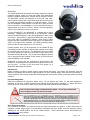
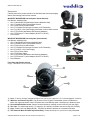
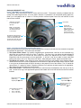
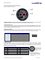
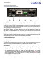
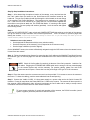
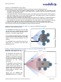
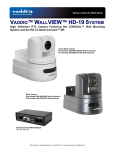
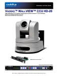
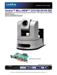
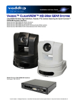
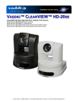
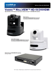
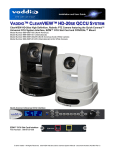
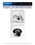
Installation and User Guide VADDIO™ WIDESHOT™ WALLVIEW™ SR Wide Angle HD Point of View Camera System with a 82.2° Horizontal Field of View Manual Lens and the Quick-Connect™ SR Interface Model Number 999-6910-000 (North America) Model Number 999-6910-001 (International) © 2014 Vaddio - All Rights Reserved. WideSHOT WallVIEW SR - Document Number 342-0695 Rev A WideSHOT WallVIEW SR Inside Front Cover - Blank WideSHOT WallVIEW SR System Document Number 342-0695 Rev A Page 2 of 20 WideSHOT WallVIEW SR TABLE OF CONTENTS Overview .................................................................................................................................................................... 4 Unpacking: ................................................................................................................................................................. 5 Front View with Feature Call-outs .......................................................................................................................... 5 Image: WideSHOT HD PTZ Camera ................................................................................................................ 5 Setting the WideSHOT Lens .................................................................................................................................. 6 Image: WideSHOT Focus Knob Removal ......................................................................................................... 6 Image: Adjusting the HD Varifocal Optical Zoom Lens ..................................................................................... 6 Rear Panel Connections with Feature Call-outs .................................................................................................... 7 Image: WideSHOT HD Camera ........................................................................................................................ 7 Quick-Connect SR Interface ...................................................................................................................................... 8 Image: Rear Panel with Feature Call-outs ........................................................................................................ 8 First Time Set-up: ...................................................................................................................................................... 8 Step By Step Installation Instructions: ................................................................................................................... 9 Framing the WideSHOT’s Video Shot ..................................................................................................................... 10 Drawing: A Small Conference Room (10’ wide x 12’ long) with a WideSHOT HD camera ............................ 10 Drawing: A Bigger, Small Conference Room (12’ wide x 16’ long) with WideSHOT HD ................................ 10 Image: Basic Wiring Configuration .................................................................................................................. 11 IR SHOT Commander Remote Control ................................................................................................................... 12 Image: Vaddio IR SHOT Commander Hand-held IR remote .......................................................................... 12 Compliance and CE Declaration of Conformity - WideSHOT ................................................................................. 13 Warranty Information ............................................................................................................................................... 14 WideSHOT WallVIEW SR General Specifications: ............................................................................................. 15 Appendix 1: Pin-outs for WideSHOT Camera ........................................................................................................ 16 Table EZCamera Power & HD Video RJ-45 Connector Pin-outs .................................................................... 16 Appendix 2: Pin-outs for Quick-Connect SR Interface ........................................................................................... 16 Table: DE-15 - YPbPr Pin-Out ........................................................................................................................ 16 Appendix 3: Communication Specification ............................................................................................................. 17 WideSHOT Command List................................................................................................................................... 17 WideSHOT Inquiry List ........................................................................................................................................ 18 Appendix 4: WideSHOT OSD Menu Tree .............................................................................................................. 19 WideSHOT WallVIEW SR System Document Number 342-0695 Rev A Page 3 of 20 WideSHOT WallVIEW SR OVERVIEW: The Vaddio WideSHOT HD camera wide angle, manual lens camera produces amazing results for small and huddle room applications where the distance between the camera and the subject is limited. The WideSHOT camera was designed as a low cost, high value, manual pan/tilt camera with a super wide-angle lens that can be set to provide the best image possible in a small environment. To that end, the WideSHOT camera sports a lens with 82.2° wide horizontal field of view with a user adjustable iris, focus and varifocal zoom of approximately 3X (3.3mm to 10.5mm). With the 3X zoom capability, even the “big” small rooms can be covered too. Like the ZoomSHOT™, the WideSHOT is a camera with a unique genealogy. Designed from the ground up, the WideSHOT camera uses the Vaddio EZCamera™ Cat-5 wiring standard for video, power and control. Using HSDS™ (high speed differential) video outputs over Cat-5 cable, the WideSHOT supplies a wide range of video resolutions that are selectable from the rear panel; from 480p/59.94YPbPr up to and including 1080p/60. The HSDS processing allows delivery of the HD video signals up to 150’ (45.72m). Image: WideSHOT HD Camera Choose between three (3) IR frequencies for the Vaddio IR Shot Commander remote controller to allow multiple cameras to be locally IR controlled with a single remote. The WideSHOT also has an OSD (on screen display) for easy set-up and basic image control that’s accessible with the IR remote. Two (2) camera configuration presets can be programmed and recalled via the remote or RS-232 and IR signal forwarding is also included. WideSHOT is paired with the tried-and-true Quick-Connect SR Interface in this package which represents a exceptional value and a very low price. So relax, for the next small room design, try a WideSHOT Wide-angle HD Camera. Image: WideSHOT Rear Panel Intended Use: Before operating the device, please read the entire manual thoroughly. The system was designed, built and tested for use indoors with the power supply provided. The use of a power supply, other than the one provided, or outdoor operation has not been tested and could damage the device and/or create a potentially unsafe operating condition. Important Safeguards: Read and understand all instructions before using. Do not operate any device if it has been dropped or damaged. In this case, a Vaddio technician must examine the product before operating. To reduce the risk of electric shock, do not immerse in water or other liquids and avoid extremely humid conditions. Use only the power supply provided with the system. Use of any unauthorized power supply will void any and all warranties. Please do not use “pass-thru” type RJ-45 connectors. These pass-thru type connectors do not work well for professional installations and can be the cause of intermittent connections which can result in the RS-232 control line failing and locking up, and/or compromising the HSDS (high speed differential) signals. For best results please use standard RJ-45 connectors and test all cables for proper pin-outs prior to use and connection to Vaddio product. Save These Instructions: The information contained in this manual will help you install and operate your product. If these instructions are misplaced, Vaddio keeps copies of Specifications, Installation and User Guides and most pertinent product drawings for the Vaddio product line on the Vaddio website. These documents can be downloaded from www.vaddio.com free of charge. WideSHOT WallVIEW SR System Document Number 342-0695 Rev A Page 4 of 20 WideSHOT WallVIEW SR UNPACKING: Carefully remove the product and all of the included parts from the packaging. Identify the following parts for each camera: WideSHOT WallVIEW SR Camera System (North America): Part Number: 999-6910-000 One (1) WideSHOT HD Wide-Angle Camera (998-6910-000) One (1) Vaddio IR SHOT Commander Remote One (1) Quick-Connect SR Interface One (1) 3-Position Phoenix-type Connector for IR Forwarding One (1) 24 VDC, 2.0 A Power Supply with Power Cord for North America One (1) Thin Profile Wall Mount with Mounting Hardware One (1) EZCamera™ Control Adapter (RJ-45-F to DB-9-F) Documentation WideSHOT WallVIEW SR Camera System (International): Part Number: 999-6910-001 One (1) WideSHOT HD Camera (998-6910-000) One (1) Vaddio IR SHOT Commander Remote One (1) Quick-Connect SR Interface One (1) 3-Position Phoenix-type Connector for IR Forwarding One (1) 24 VDC, 2.0 A Power Supply One (1) Euro Power Cable One (1) UK Power Cable One (1) Thin Profile Wall Mount with Mounting Hardware One (1) EZCamera™ Control Adapter (RJ-45-F to DB-9-F) Documentation Front View with Feature Call-outs Image: WideSHOT HD PTZ Camera ① ⑤ ② ③ ④ ⑥ 1) Lens: 3.3mm to 10.5mm Varifocal HD Zoom Lens (16:9), 82.2° wide end , 27.4° tele end (approx. 3X zoom) 2) IR Sensor and Power/Tally LED: The IR sensor for the IR SHOT Commander remote is located here. Below it is a light pipe where a blue LED power and a red LED tally reside. Both light up to produce purple. 3) Focus Knob Retention Screw: Remove screw and knob to manually set zoom and iris (see next page). 4) The Yoke: For manual pan and tilt. Tilt range is ± 30° and Pan is limited to the service loop of the cabling. 5) Logo: Really Cool Logo Badge (RCLB). The RCLB is affixed to the base in a recessed ovoid area. 6) The Aluminum Base and Steel Cylindrical Body: Please don’t drop it on your foot, it’s fairly substantial. WideSHOT WallVIEW SR System Document Number 342-0695 Rev A Page 5 of 20 WideSHOT WallVIEW SR Setting the WideSHOT Lens Image: WideSHOT Focus Knob Removal You may ask, “Why would anyone want to remove the focus knob?” The answer is directly correlated with the quality of this wide-angle HD lens. It is not a plastic “webcam”, but instead it is an exceptional quality glass lens, rated up to 3-megapixel with a 3.3mm to 10.5mm precision varifocal optical zoom lens with manual iris and manual focus controls. IR Window (recessed) & the blue/red LED light pipe Note: The IR window is small, so please aim the remote at the front of the camera Focus Knob Focus Knob attachment point: With a flat blade “tweaker” type screw driver, remove the screw and carefully pull off the focus knob. Exceptional quality glass lens, rated up to 3-megapixel with a 3.3mm to 10.5mm precision varifocal zoom lens with manual zoom, iris and focus controls. Image: Adjusting the HD Varifocal Optical Zoom Lens After removing the focus knob screw and carefully sliding off the “snug” focus knob, the lens controls are exposed and available for adjustment. The controls are as follows: 1) The Optical Zoom Control: By carefully untightening the knurled screw a half turn on the innermost ring, adjust the ring to either the wide (W) or tele (T) direction. The focus ring, now without knurled adjustment screw (screw taken out to remove the focus knob) will need to be adjusted as the zoom is changed. Experiment with the zoom range to fit the application. A full 82.2° may be too wide in some cases and tailoring the zoom to 65° to 70° may fit the room better. After setting the control, tighten the knurled screw. 2) The Manual Iris Control: After setting the zoom range and focusing on the subject’s at the distance that the camera will be used, the iris can be adjusted to limit the amount of light that the image sensor receives, which in turn gives an increased depth of field for focusing on the people in front of the camera. The “O” stands for open and the “C” stands for closed. Experiment with the iris to achieve the best results for the application. After setting the control, tighten the knurled screw. 3) The Focus Control: The outermost ring is the focus control and can be adjusted to the near (N) or far (F) side. Set the focus ring to the approximate position and reattach the focus knob with the knurled screw when finished. Manual Iris Control (Middle ring) Adjust Open Close Manual Zoom Control (Innermost ring) Adjust Wide Tele Manual Focus Control (Outermost ring) Adjust Near Far Lens Positions from Factory IRIS - Full Open Zoom - Full Wide Focus - user to set WideSHOT WallVIEW SR System Document Number 342-0695 Rev A Page 6 of 20 WideSHOT WallVIEW SR Rear Panel Connections with Feature Call-outs Image: WideSHOT HD Camera ② ① ④ ③ 1) RS-232 & IR Out: The RS-232 accepts modified VISCA protocol for camera control, as well as transmits IR signaling received by the front IR receiver, which can be transmitted to third party devices 2) EZ Power/Video Port: This RJ-45 connector is only used with the Quick-Connect SR, Quick-Connect DVI-D/HDMI SR Interface, QuickConnect USB and USB Mini Interfaces to supply power and return HSDS (differential) video from the camera over Cat-5 cable up to distance of 150’ (45.72m). 3) Dip Switch Settings: Settings for IR remote frequency, IR receiver on/off, image flip, test bars and defaults can be configured on these switches. See the Switch Settings page for additional information. The dip switch settings are as follows: Dip Switch 1 2 3 4 5 6 All Down Function Up = IR1, Down = IR2 Up = IR 1 or 2, Down = IR3 Up=IR ON, Down = IR OFF Up = Normal Image, Down = Image Flip Test Bars Update Position - Leave UP unless updating firmware Reset to Defaults - with power cycle 4) HD Video Select: A rotary switch allows the user to choose the video output resolution for the camera. After setting or changing the resolution, reboot the camera to ensure proper operation. If an unassigned rotary selection position is chosen (3, 9, A, B, C or D), the camera will output a medium grey video privacy mask. The HD Video Select Rotary Switch Settings are as follows: Rotary 0 1 2 3 4 5 6 7 Resolutions 720p/59.94 1080i/59.94 1080p/59.94 -720p/50 1080i/50 1080p/50 480p/59.94 Rotary 8 9 A B C D E F WideSHOT WallVIEW SR System Document Number 342-0695 Rev A Resolutions 576p/59.94 -----1080p/29.97 1080p/25 Point the notch in the switch stem to assign the rotary position (the camera is on Position 1 1080i/59.94). Important Notes: 1) 2) For IP or USB 2.0 Streaming, use position “0” (720p/59.94) for best results Set the rotary switch to an unassigned position and a medium grey privacy mask is displayed. Page 7 of 20 WideSHOT WallVIEW SR QUICK-CONNECT SR INTERFACE Image: Rear Panel with Feature Call-outs ① ② ③ ④ ⑤ 1) Power Input: 5.5mm OD x 2.5mm ID coaxial connector for the provided PowerRite 24 VDC, 2.0 Amp power supply. 2) EZCamera Power & HD Video: A single Cat-5 connection between the EZCAMERA POWER & HD VIDEO RJ-45 connector and the camera’s EZ Power HD Video Port on the HD-19 camera extends power and video. Power is fed to the camera and HSDS video is returned from the camera on the same Cat-5. 3) HD Video Output: DE-15 connector outputs the YPbPr analog component HD video, which was extended from the camera over Cat-5 cable. SD video resolutions (Y/C and CVBS formats) are not supported by the Quick-Connect SR Interface, however analog component SD video is supported. 4) IR Output: With the IR pass-thru turned ON (see camera dip switch settings), IR from third-party IR remote controls can be sent through the WideSHOT camera to third-party equipment, such as hardware videoconferencing codecs. IR can be used as either modulated (through the air) or non-modulated (wired) signals). 5) RS-232 Input & Output Jacks: These RJ-45 connectors allow an external controller to route through the Quick-Connect SR for ease of cabling. FIRST TIME SET-UP The WideSHOT was designed to be very easy to use and operate. There is documentation at the back of this manual for pin-outs of the connectors on the Quick-Connect SR Interface and WideSHOT HD camera. Before Installing: Choose the camera mounting location by paying close attention to camera viewing angles, lighting conditions, possible line of site obstructions, and checking for in-wall obstructions where the camera is to be mounted. Always pick a mounting location that will optimize the performance of the camera. The Thin Profile Wall Mount for the WideSHOT can be mounted directly to a 1-gang wall box or can be mounted using only dry wall anchors. For Power/Video and RS-232 signals, use standard Cat-5 cable (568B termination and real RJ-45 connectors) from the EZ-POWER VIDEO and RS-232 ports on the back of the WideSHOT camera to the Quick-Connect SR Interface. The EZ-POWER VIDEO jack on the camera is highlighted red as a reminder that there is 24 VDC power on that Cat-5 cable. WideSHOT WallVIEW SR System Document Number 342-0695 Rev A Page 8 of 20 WideSHOT WallVIEW SR Step By Step Installation Instructions: Step 1: After determining the optimum location of the camera, route, mark and test the two Cat-5 cables from the camera to the Quick-Connect SR Interface located at the head-end. The two Cat-5 cables should feed-through the hole located on the rear flange of the supplied Thin Profile Wall Mount. The bracket can be mounted to a 1-gang wall box. If the mount is to be mounted on a 1-gang wall box, use the screws supplied with the wall box cover plate to attach the Thin Profile Wall Mount. If mounting to the drywall with wall anchors, use two quality wall anchors (provided). Level the mount and tighten the mounting screws. Step 2: Using the HD VIDEO SELECT rotary switch and CAMERA SETTINGS dip switches on the back of the camera, set up the camera’s output resolution and functional preferences. There are tables on previous pages that identify the choices…maybe keep these tables handy for future use…or you can easily look them up on the Vaddio website (vaddio.com) when needed. Switches to set on the camera: Set the desired HD Resolution with the rotary selection switch. Set the IR frequency of the camera (if it is to respond to the IR remote control). Set the image orientation (normal or flipped). On the WideSHOT camera, the remote will basically navigate through the OSD menus since the camera’s zoom, iris and focus are manual. Step: 3: Follow the sample wiring diagram for connecting the Cat-5 cables to the WideSHOT and Quick-Connect SR Interface (yep, on the next page, but read and understand the rest of these instructions especially the next note). NOTE: Check all Cat-5e cables for continuity in advance of the final connection. Label the Cat5e cables. Plugging the EZ POWER HD VIDEO cable into the wrong RJ-45 may cause damage to the camera system and void the warranty. For premise cabling, please use real RJ-45 connectors and crimpers. Please don’t use the pull through or EZ type of RJ-45 connectors. Step 4: Place the camera onto the camera mount and use the provided ¼”-20 screws to secure the camera to the mount. To dress the cabling, push the extra cable back into the wall opening. Step 5: Connect the Vaddio 24 VDC, 2.0 Amp power supply to a power outlet and to the Quick Connect SR Interface. Power will travel down the Power/Video Cat. 5 cable to the camera. The camera will boot up and in a few seconds, HSDS (differential) video will travel back down the Cat-5 cable and be ready to accept control information from the IR remote control or other camera controller. To insure proper continuity of control and operation of the cameras, the RS-232 controller (control system or joystick) should be powered on after the camera. WideSHOT WallVIEW SR System Document Number 342-0695 Rev A Page 9 of 20 WideSHOT WallVIEW SR FRAMING THE WIDESHOT’S VIDEO SHOT When framing the shot with a WideSHOT Camera, consider and review the following elements: The area should be well lit and without reflective surfaces. For wall surfaces, use a flat paint or wall coverings to minimize audio reflections. Use neutral colors, for example; pale grey, pale blue or beige that are easy for any camera to process. Avoid white and black or a stark contrast color pallet, avoid placing a big old white board in the background, and avoid complex décor in view of the camera (modern art). Avoid glass, chrome, mirrors, and glass on table tops to minimize the lighting and audio reflections. Always avoid having a window in the camera shot as sunlight can be disruptive of camera performance. Window treatments are a must for rooms with windows to achieve evenly lit space without direct sunlight. Never position the camera so that any ceiling lights are in the video frame. No one sits anywhere near the ceiling and direct lighting in the frame can be problematic for the automatic functions of the camera. The bottom line is simple, give the camera a chance to work well in the room and excellent video is the result. There are many room set up primers available on today’s internet for reference. Drawing: A Small Conference Room (10’ wide x 12’ long) with a WideSHOT HD camera WideSHOT set at the wide end (82.2°). 12’ (3.66m) The WideSHOT HD camera set to the full wide end of 82.2° is an excellent choice for small (huddle) conferencing rooms that range from 8’ (2.44m) to 12’ (3.66m) in width x depth. 82.2° In this example, the table front is 4’ (1.22m) away from the camera and the WideSHOT can easily capture all of the meeting participants from this distance The WideSHOT can be manually zoomed into a tighter shot for a conference room with fewer participants as well. 10’ (3.05m) 4’ (1.22m) Drawing: A Bigger, Small Conference Room (12’ wide x 16’ long) with WideSHOT HD WideSHOT set at the wide end 82.2° - Lt. Blue WideSHOT reset to approx. 58° - Red 16’ (4.88m) The WideSHOT HD camera set to the full wide end of 82.2°, in this example, is too wide for this room and will not render any real detail such as facial expressions and other mannerisms of the meeting participants. 82.2° 58.0° 12’ (3.66m) The WideSHOT can be zoomed into a tighter shot (58°or tighter - rose colored viewing angle) allowing all the subjects in this room be seen on camera while still providing the details needed for effective visual communications. Please see the Setting the WideSHOT Lens section on page 6. WideSHOT WallVIEW SR System Document Number 342-0695 Rev A Page 10 of 20 WideSHOT WallVIEW SR Image: Basic Wiring Configuration WideSHOT Rear View Maximum Cat-5 Cable Distance for the WideSHOT Camera is 150’ (45.72m) IR SHOT Commander Remote for access to OSD RS-232 Cat-5 HSDS (differential) HD Video & 24 VDC Power One (1) Cat-5 Cable ← YPbPr (differential) Power → Rear Panel Quick-Connect SR Interface YPbPr 24VDC, 2.0 A PowerRite Power Supply RS-232 HD Monitor - YPbPr Inputs (Simulated HD Video Feed) Serial Control for Color Presets, Scenes and configuration (if required) Most camera settings can be set with the IR SHOT Commander using the OSD. WideSHOT WallVIEW SR System Document Number 342-0695 Rev A Page 11 of 20 WideSHOT WallVIEW SR IR SHOT COMMANDER REMOTE CONTROL Spatially Efficient IR Remote Controller for ZoomSHOT™ and WideSHOT™ Camera Systems The Vaddio IR SHOT Commander was designed to work with the Vaddio ZoomSHOT and WideSHOT camera systems and is compatible with the PowerVIEW™, ClearVIEW™ cameras and the WallVIEW™ camera system packages. The Vaddio IR SHOT Commander is compatible with the following Vaddio camera packages: ZoomSHOT and WideSHOT Camera Systems (shipped with these products) Vaddio ClearVIEW HD-18, HD-19, HD-20, PowerVIEW HD-22, HD-30 and REVEAL™ HD-18 (limited functionality) The Vaddio IR Shot Commander is also compatible with the Sony® EVI series and the BRC series PTZ cameras. Basic Instructions: Pick the IR Frequency to match the dip switch setting of the camera. Operate the remote (but not too fast). Note: The Pan/Tilt/Zoom controls are not used with the manual lens of the WideSHOT HD Camera. Image: Vaddio IR SHOT Commander Hand-held IR remote ZOOM OUT RedI LED indicates IR transmission and ZOOM P-STORE OSD On Screen Display Menu (if applicable) PRESET 1 the brightness indicates battery strength IR 1 Power On/Off Camera Standby OK, Enter, Select and Camera Home Arrow Keys X 4 Pan Left, Pan Right, Tilt Up, Tilt Down Menu Navigation Pan Functions Not Used with WideSHOT Zoom Camera OUT (wide) Zoom Functions Not Used with WideSHOT Zoom Camera IN (telephoto) Zoom Functions Not Used with WideSHOT Preset Button - Setting Presets Move the camera into position Push and hold P-STORE button Touch buttons 1 or 2 to set Preset Recalls ZoomSHOT Preset 1 or Preset 2 (for Color and CCU Scenes) *WideSHOT uses a manual lens Quick Specs IR Range Batteries Keys (buttons) Dimensions LxWxH LED Indicator Compatible Cameras 20’ to 30’ (6m to 9m) Select IR Frequencies (3) Allows up to 3 cameras to be controlled in a room with one (1) IR Remote Note: Camera dip switches set IR frequency. 2 x AAA (Batteries not shipped with 998-2101-001) 15 Silicone Rubber Keys 4.53” (115mm) x 1.57” (40mm) x 1.1” (28mm) Red LED Illuminates when transmitting IR, Brightness indicates battery strength Ships with ZoomSHOT and WideSHOT. Compatible with all Vaddio ClearVIEW, PowerVIEW cameras (limited function set) and most Sony BRC & EVI cameras, but with limited functionality WideSHOT WallVIEW SR System Document Number 342-0695 Rev A Page 12 of 20 WideSHOT WallVIEW SR COMPLIANCE AND CE DECLARATION OF CONFORMITY - WIDESHOT Compliance testing was performed to the following regulations: FCC Part 15 (15.107, 15.109), Subpart B ICES-003, Issue 4: 2004 EN 55022 A: 2006 + A1: 2007 KN22 2008 (CISPR 22: 2006) KN24 2008 (CISPR 24: 1997 + A1: 2000 + A2: 2002) EMC Directive 2004/108/EC EN 55024: A2: 2003 Class A Class A Class A Class A Class A Class A Class A FCC Part 15 Compliance This equipment has been tested and found to comply with the limits for a Class A digital device, pursuant to Part 15, Subpart B, of the FCC Rules. These limits are designed to provide reasonable protection against harmful interference when the equipment is operated in a commercial environment. This equipment generates, uses, and can radiate radio frequency energy and, if not installed and used in accordance with the instruction manual, may cause harmful interference to radio communications. Operation of this equipment in a residential area is likely to cause harmful interference in which case the user will be required to correct the interference at his/her own expense. Operation is subject to the following two conditions: (1) This device may not cause interference, and (2) This device must accept any interference including interference that may cause undesired operation of the device. Changes or modifications not expressly approved by Vaddio can affect emission compliance and could void the user’s authority to operate this equipment. ICES-003 Compliance This digital apparatus does not exceed the Class A limits for radio noise emissions from digital apparatus set out in the Radio Interference Regulations of the Canadian Department of Communications. Le présent appareil numérique n’emet pas de bruits radioélectriques dépassant les limites applicables aux appareils numeriques de la classe A préscrites dans le Règlement sur le brouillage radioélectrique édicte par le ministère des Communications du Canada. European Compliance This product has been evaluated for Electromagnetic Compatibility under the EMC Directive for Emissions and Immunity and meets the requirements for a Class A digital device. In a domestic environment this product may cause radio interference in which case the user may be required to take adequate measures. Standard(s) To Which Conformity Is Declared: EMC Directive 2004/108/EC EN 55022 A: 2006 + A1: 2007(CISPR 22:2005/A1:2005) EN 55024: A2: 2003 EN 61000-4-2: 1995 + Amendments A1: 1998 + A2: 2001 EN 61000-4-3: 2006 + A1: 2008 EN 61000-4-4: 2004 + Corrigendum 2006 EN 61000-4-5: 2006 EN 61000-4-6: 2009 EN 61000-4-8: 2010 EN 61000-4-11: 2004 KN24 2008 (CISPR 24: 1997 + A1: 2000 + A2: 2002) EN 61000-4-2 EN 61000-4-3 EN 61000-4-4 EN 61000-4-5 EN 61000-4-6 EN 61000-4-8 EN 61000-4-11 IEC 60950-1:2005 (2nd Edition); Am 1:2009 EN 60950-1:2006+A11:2009+A1:2010+A12:2011 WideSHOT WallVIEW SR System Document Number 342-0695 Rev A Class A Immunity Electrostatic Discharge Radiated Immunity Electrical Fast Transients Surge Immunity Conducted Immunity Power Frequency Magnetic Field Voltage Dips, Interrupts and Fluctuations IT Immunity Characteristics Electrostatic Discharge Radiated Immunity Electrical Fast Transients Surge Immunity Conducted Immunity Power Frequency Magnetic Field Voltage Dips, Interrupts and Fluctuations Safety Safety Page 13 of 20 WideSHOT WallVIEW SR WARRANTY INFORMATION (See Vaddio Warranty, Service and Return Policies posted on vaddio.com for complete details): Hardware* Warranty: Two (2) year limited warranty on all parts and labor for Vaddio manufactured products. Vaddio warrants its manufactured products against defects in materials and workmanship for a period of two years from the day of purchase, to the original purchaser, if Vaddio receives notice of such defects during the warranty. Vaddio, at its option, will repair or replace products that prove to be defective. Vaddio manufactures its hardware products from parts and components that are new or equivalent to new in accordance with industry standard practices. Exclusions: The above warranty shall not apply to defects resulting from improper or inadequate maintenance by the customer, customers applied software or interfacing, unauthorized modifications or misuse, mishandling, operation outside the normal environmental specifications for the product, use of the incorrect power supply, modified power supply or improper site operation and maintenance. OEM products and products manufactured by other companies are excluded and are covered by the manufacturer’s warranty. Vaddio Customer Service: Vaddio will test, repair, or replace the product or products without charge if the unit is under warranty. If the product is out of warranty, Vaddio will test then repair the product or products. The cost of parts and labor charge will be estimated by a technician and confirmed by the customer prior to repair. All components must be returned for testing as a complete unit. Vaddio will not accept responsibility for shipment after it has left the premises. Vaddio Technical Support: Vaddio technicians will determine and discuss with the customer the criteria for repair costs and/or replacement. Vaddio Technical Support can be contacted through one of the following resources: e-mail support at [email protected] or online at vaddio.com. Return Material Authorization (RMA) Number: Before returning a product for repair or replacement request an RMA from Vaddio’s technical support. Provide the technician with a return phone number, e-mail address, shipping address, product serial numbers and original purchase order number. Describe the reason for repairs or returns as well as the date of purchase. See the General RMA Terms and Procedures section for more information. RMA’s are valid for 30 days and will be issued to Vaddio dealers only. End users must return products through Vaddio dealers. Include the assigned RMA number in all correspondence with Vaddio. Write the assigned RMA number clearly on the shipping label of the box when returning the product. All products returned for credit are subject to a restocking charge without exception. Voided Warranty: The warranty does not apply if the original serial number has been removed or if the product has been disassembled or damaged through misuse, accident, modifications, use of incorrect power supply, use of a modified power supply or unauthorized repair. Shipping and Handling: Vaddio will not pay for inbound shipping transportation or insurance charges or accept any responsibility for laws and ordinances from inbound transit. Vaddio will pay for outbound shipping, transportation, and insurance charges for all items under warranty but will not assume responsibility for loss and/or damage by the outbound freight carrier. If the return shipment appears damaged, retain the original boxes and packing material for inspection by the carrier. Contact your carrier immediately. Products not under Warranty: Payment arrangements are required before outbound shipment for all out of warranty products. Other General Information: Care and Cleaning Do not attempt to take this product apart at any time. There are no user-serviceable components inside. Do not spill liquids in the product Keep this device away from food and liquid For smears or smudges on the product, wipe with a clean, soft cloth Use a lens cleaner on the lens - not a hanky Do not use any abrasive chemicals. Operating and Storage Conditions: Do not store or operate the device under the following conditions: Temperatures above 40°C (104°F) or temperatures below 0°C (32°F) High humidity, condensing or wet environments In inclement weather In swimming pools or under waterfalls Dry environments with an excess of static discharge In orbit (vacuum issue) Under severe vibration WideSHOT WallVIEW SR System Document Number 342-0695 Rev A Page 14 of 20 WideSHOT WallVIEW SR WideSHOT WallVIEW SR General Specifications: WideSHOT Camera System Part Numbers Image Sensor Video Output Resolutions Lens/ Focal Length Horizontal Viewing Angle Video S/N Ratio Minimum Illumination Serial Control Protocol Manual Pan/Tilt Range Preset Positions Tally Light Camera Connectors HD Video Select Camera Settings Thin Profile Wall Mount User Controls Materials & Weight Dimensions: WideSHOT WallVIEW 999-6910-000 (North America) WideSHOT WallVIEW 999-6910-001 (International) 1/3-Type Progressive Scan CMOS Sensor with 1.3 Megapixels HD: 1080/59.94/50/30/25, 1080i/59.94/50, 720p/59.94/50 SD: 480p/59.94 & 576p/50 Approx. 3X Optical Zoom, 3.3mm to 10.mm manual focus 82.2° Wide End to 3.2° Tele End, 27.4° Tele End - 16:9 Format >50 dB 0.2 LUX (1/30 Shutter Speed) Color RS-232 (Modified VISCA) Pan: Limited to service loop of cabling, yoke and base are mechanical only Tilt: ± 30° Invertible for Ceiling Mount Manual Red LED available through RS-232 Control Two (2) RJ-45 Jacks: EZ-Power VIDEO RJ-45 Jack for use with Quick-Connect - Supplies power to the camera and returns differential HD video from the camera RS-232 RJ-45 Jack (RS-232 Communication and IR Out (with Quick-Connect -SR Interfaces) 16-Position Rotary Switch: Used to set HD Video Resolution Output 6-Position Dip Switch: For IR Freq., Baud Rate 9600, Image Flip & Test Bars 16-Position Rotary Switch for Output Resolution Settings 535-2000-237 (Provided with WideSHOT WallVIEW Systems) Black powder coating, Sized to fit on 1-gang wall box or drywall mounting IR SHOT Commander with OSD for set-up and RS-232 Aluminum & Steel, Weight = 2.45643 lbs. (1.1142179kg) Tube: 3.5” ( 88.9mm) Diameter x 5.125” (130.175mm) Long (including front bezel and focus knob) Base: 5.5” (139.7mm) Diameter Overall Height: 5.5” (139.7mm) Tall Quick-Connect SR Interface Connectors Power Supply Dimensions (H x W x D) Weight Accessory Power Connector: 5.5mm OD, 2.5mm ID coaxial connector Power/Video RJ-45: Supplies power to, and differential HD video from the camera Video Output: DE-15 connector for HD Analog Component (YPbPr) video only (No SD Support) IR Output: Transmits modulated or non-modulated IR signals received from the camera’s IR receiver RS-232 IN RJ-45: Accepts RS-232 from ProductionVIEW or other external control systems RS-232 OUT RJ-45: Sends RS-232 from Quick-Connect SR to the camera 24 VDC, 2.0 Amp 1/3 Rack Size - 1.6” (40.64mm ) H x 5.5” (139.7mm) W x 3.25” (82.5500000000001mm) D 0.45 lbs. ( 0.20411657 kg) Rack Mount Adapter: 998-6000-002 - Holds three (3) Quick-Connect SR Interfaces Planet in Front Page Header: Venus (filtered for detail) WideSHOT WallVIEW SR System Document Number 342-0695 Rev A Page 15 of 20 WideSHOT WallVIEW SR APPENDIX 1: PIN-OUTS FOR WIDESHOT CAMERA Table EZCamera Power & HD Video RJ-45 Connector Pin-outs WideSHOT EZPOWER HD VIDEO PORT Pin YPbPr 1 Power+ 2 Power3 Y+ 4 PB+ 5 PB 6 Y7 PR+ 8 PR- EZ POWER HD VIDEO 12345678 Important Note: The EZ POWER HD VIDEO RJ-45 Connector is for use with the Quick-Connect SR, Quick-Connect DVI/HDMI SR, Quick-Connect USB and USB Mini Interfaces ONLY (568B Wiring Standard). The video signals are differential (HSDS™) and can only be received by the interfaces above. WideSHOT Camera RS-232 Port Pin # Function Pin - 1 N/A Pin - 2 N/A Pin - 3 N/A Pin - 4 IR Output (Diff Signal to Quick-Connect SR Only) Pin - 5 IR Ground (Diff Signal to Quick-Connect SR Only) Pin - 6 Digital GND Pin - 7 RXD (from TXD of control source) Pin - 8 TXD (to RXD of control source) RS-232 12345678 APPENDIX 2: PIN-OUTS FOR QUICK-CONNECT SR INTERFACE Table: DE-15 - YPbPr Pin-Out Pin 1 2 3 4 5 6 7 8 9 10 11 12 13 14 15 YPbPr Pr Y Pb Pr GND Y GND Pb GND GND - WideSHOT WallVIEW SR System Document Number 342-0695 Rev A Page 16 of 20 WideSHOT WallVIEW SR APPENDIX 3: COMMUNICATION SPECIFICATION Communication Speed: 9600 bps (default) Start bit: 1 Stop bit: 1 Data bits: 8 Parity: None No Flow control 12345678 Pin # 1) 2) 3) 4) 5) 6) 7) 8) RJ-45 RS-232 and IR Out Pins Unused Unused Unused IR Output (Diff Signal to Quick-Connect SR) IR Ground (Diff Signal to Quick-Connect SR) GND (GND of IR Short Range - Pin 3) RXD (from TXD of control source) TXD (to RXD of control source) NOTE: The Vaddio WideSHOT Control Protocol is similar, but not identical to the Sony® VISCA™ command set in order to be compatible with several popular control devices. Not all VISCA commands are supported and there are many WideSHOT specific commands in the following Command and Inquiry Lists. WideSHOT Command List Command Set Address Set IF_Clear Command Cancel CAM_Power CAM_WB CAM_RGain CAM_BGain CAM_AE CAM_Aperture CAM_Bright CAM_IDWrite Tally Command Broadcast Broadcast On Off(Standby) Auto Manual Reset Up Down Direct Reset Up Down Direct Full Auto Manual Reset Up Down Direct Reset Up Down Direct BLK.Enhance CRM.Enhance DNR.Enhance On Off Pedestal Chroma Noise Reduction AGC.Enhance AGC Mode CAM_Shutter Reset Up Down Direct Command Packet 88 30 01 FF 88 01 00 01 FF 8x 2p FF 8x 01 04 00 02 FF 8x 01 04 00 03 FF 8x 01 04 35 00 FF 8x 01 04 35 05 FF 8x 01 04 03 00 FF 8x 01 04 03 02 FF 8x 01 04 03 03 FF 8x 01 04 43 00 0p 0q 0r FF 8x 01 04 04 00 FF 8x 01 04 04 02 FF 8x 01 04 04 03 FF 8x 01 04 44 00 0p 0q 0r FF 8x 01 04 39 00 FF 8x 01 04 39 03 FF 8x 01 04 02 00 FF 8x 01 04 02 02 FF 8x 01 04 02 03 FF 8x 01 04 42 00 0p 0q 0r FF 8x 01 04 0D 00 FF 8x 01 04 0D 02 FF 8x 01 04 0D 03 FF 8x 01 04 4D 00 00 0p 0q FF 8x 01 04 22 0p 0q 0r 0s FF 8x 01 7E 01 0A 00 02 FF 8x 01 7E 01 0A 00 03 FF 8x 01 7E 53 00 0p 0q 0r FF 8x 01 7E 55 00 0p 0q 0r FF 8x 01 7E 58 00 0p 0q 0r FF 8x 01 7E 59 00 FF 8x 01 7E 59 01 FF 8x 01 7E 59 02 FF 8x 01 04 0A 00 FF 8x 01 04 0A 02 FF 8x 01 04 0A 03 FF 8x 01 04 4A 00 00 00 0p FF WideSHOT WallVIEW SR System Document Number 342-0695 Rev A Comments Address Set (Daisy chain) IF Clear p:socket number(1,2) Power On/Off Normal Auto Manual White Balance pqr: Red (0x0-0x010) Default 8 pqr: Blue (0x0-0x010) Default 8 Auto Exposure Mode Manual Control Mode pqr: Sharpness (0x0-0x010) Default 8 pqr: Bright (0x0-0x0010) Default 8 pqrs:0x0000 – 0xFFFF pqr: Contrast (0x0-0x010) Default 8 pqr: Saturation (0x0-0x010) Default 8 pqr: Noise reduction (0x0- 0x010) Default 0 Low Auto Default High p: Shutter Speed (0-8) Default 8 Page 17 of 20 WideSHOT WallVIEW SR WideSHOT Inquiry List Inquiry Command CAM_PowerInq Command 8x 09 04 00 FF CAM_WBModeInq 81 09 04 35 FF CAM_AEModeInq 8x 09 04 39 FF CAM_IDInq CAM_ApertureInq CAM_RGain CAM_BGain CAM_Bright CAM_ShutterPosInq TallyInq 8x 09 04 22 FF 8x 09 04 42 FF 8x 09 04 43 FF 8x 09 04 44 FF 8x 09 04 4D FF 8x 09 04 4A FF 8x 09 7E 01 0A FF BLK.Enhance CRM.Enhance DNR.Enhance AGC.Enhance 8x 09 7E 53 FF 8x 09 7E 55 FF 8x 09 7E 58 FF 8x 09 7E 59 FF Response Packet y0 50 02 FF y0 50 03 FF y0 50 00 FF y0 50 05 FF y0 50 00 FF y0 50 03 FF y0 50 0p 0q 0r 0s FF y0 50 00 0p 0q 0r FF y0 50 00 0p 0q 0r FF y0 50 00 0p 0q 0r FF y0 50 00 0p 0q 0r FF y0 50 00 00 00 0p FF y0 50 02 FF y0 50 03 FF y0 50 00 0p 0q 0r FF y0 50 00 0p 0q 0r FF y0 50 00 0p 0q 0r FF y0 50 00 FF y0 50 01 FF y0 50 02 FF Comments On Off(Standby) Auto Manual Auto Exposure Mode Manual Control Mode pqrs:0x0000 – 0xFFFF pqr: Sharpness (0x00-0x010) pqr: Red (0x00-0x010) pqr: Blue (0x00-0x010) pqr: Bright (0x00-0x010) p: Shutter Speed (0-8) On Off pqr: Contrast (0x00-0x010) pqr: Saturation (0x00-0x010) pqr: Noise reduction (0x00- 0x010) Low Auto High Shutter Speeds: 0:1/7680, 1:1/3840, 2:1/1920, 3:1/960, 4:1/480, 5:1/240, 6:1/120, 7:1/60, 8:Auto Notes: The Camera module does not support an Auto White Balance option. The selection (Manual/Auto) resets the Red and Blue Gain to defaults. Auto White Balance inquiry will return “Auto” if Red and Blue are at default levels, manual if not. The Camera module does not support an Auto Exposure option. The Auto selection will reset Contrast, Saturation, Brightness, and shutter speed to defaults. Auto Exposure inquiry will return Auto if Contrast, Saturation, Brightness, and shutter are at defaults. Manual if not. WideSHOT WallVIEW SR System Document Number 342-0695 Rev A Page 18 of 20 WideSHOT WallVIEW SR APPENDIX 4: WIDESHOT OSD MENU TREE Menu PICTURE COLOR DAY/NIGHT Controls BRIGHTNESS CONTRAST SHARPNESS BKLEVEL (Black Level) NR (Noise Reduction) HFLIP (Horizontal Flip) VFLIP (Vertical Flip) RETURN MODE (not used) SHUTTER AGC ANTICR AUTOIRIS RETURN SPECIAL EXIT Default 8 8 8 8 0 OFF OFF 0-16 0-16 0-16 0-16 0-16 0-16 0-16 8 8 8 8 8 8 8 BW - AUTO COLOR 0S - 5S - 10S COLOR 0-16 LOW - AUTO HIGH OFF - AUTO - ON OFF - ON 8 AUTO REDGAIN GREENGAIN BLUEGAIN REDGREEN REDBLUE BLUEGREEN SATURATION RETURN DELAY (Time) RETURN EXPOSURE Range/Modes 0-16 0-16 0-16 0-16 0-16 OFF - ON OFF - ON 5S AUTO OFF Notes Detail Pedestal Adjustment Image Position (side to side) To invert camera image H To invert camera image V Return to Main Menu Combination Color Adjustment Combination Color Adjustment Combination Color Adjustment Chroma Return to Main Menu Auto mode automatically drops from Color to B/W when the light level is to low - NOT USED NOT USED Return to Main Menu Automatic Gain Control Anti-Color Rolling/Hunting Lens has Manual Iris Return to Main Menu TITLE PAL/NTSC OFF - ON PAL - NTSC OFF NTSC FPS (Frames/Second) DEFAULT (Sets to Defaults) RESET (Restarts Camera) VERSION (Software Version) RETURN 50/60 - 25/30 Enter Enter 201X-XXXX 50/60 Exit WideSHOT WallVIEW SR System Document Number 342-0695 Rev A Set to NTSC 50/60 - North America Set to PAL 50/60 - International Don’t use 25/30 unless necessary Firmware build info Return to Main Menu Exists OSD Mode Page 19 of 20 WideSHOT WallVIEW SR Toll Free: 800-572-2011 ▪ Phone: 763-971-4400 ▪ FAX: 763-971-4464 www.vaddio.com ©2014 Vaddio - All Rights Reserved. Reproduction in whole or in part without written permission is prohibited. Specifications and pricing are subject to change without notice or obligation. Vaddio, WideSHOT, ZoomSHOT, ProductionVIEW, WallVIEW, EZCamera, Quick-Connect and HSDS are trademarks of Vaddio. All other trademarks are property of their respective owners. Document Number 342-0695 Rev A WideSHOT WallVIEW SR System Document Number 342-0695 Rev A Page 20 of 20