1
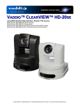
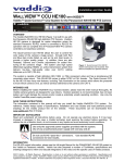
Installation and User BLURB Guide IN-CEILING™ HALF-RECESSED ENCLOSURES For the Vaddio™ ClearVIEW™, PowerVIEW™ and RoboSHOT™ HD PTZ Cameras Part Number: 999-2225-050 for HD-Series Cameras Part Number: 999-2225-150 for RoboSHOT Cameras ©2014 Vaddio - All Rights Reserved ● IN-Ceiling Half-Recessed Enclosure for HD and RoboSHOT Cameras ● Document Number 342-0177 Rev. E IN-Ceiling Half-Recessed Enclosure for HD Series and RoboSHOT Cameras Overview: Vaddio’s IN-Ceiling, Half-Recessed Enclosure is an attractive, easy to install, partially recessed and inverted, PTZ camera mounting system. IN-Ceiling Half-Recessed Enclosure is compatible with the all WallVIEW systems (ClearVIEW and PowerVIEW (HD-30/22/20SE/20/19/18) and the RoboSHOT series camera systems. The enclosure features a sealed, recessed, metal ceiling camera enclosure with one-piece tile support brace, white trim ring and mounting hardware kit. The white trim ring has an active IR receiver and there is an IR emitter board, powered by the 24 VDC Quick-Connect interfaces (Quick-Connect USB, Quick-Connect USB Mini, Quick-Connect SR and Quick-Connect DVI/HDMI-SR) on the inside of the enclosure to ensure full compatibility with the Vaddio IR Remote Commander. In-Ceiling, Half-Recessed Enclosure shown with the ClearVIEW HD-20SE AW Arctic White PTZ The IN-Ceiling enclosure is compatible with the following camera systems using RS-232 control only; ClearVIEW and PowerVIEW Series cameras (locally powered), all WallVIEW CCU Systems (powered by the CCU). These systems do not use the IR Receiver/Emitter circuit inside the enclosure. The IN-Ceiling Half-Recessed Enclosure is an appealing half-recessed mounting solution. So relax, and try an INCeiling, Half-Recessed camera enclosure today. And always remember, camera systems are sold separately. Intended Use: Before operating the device, please read the entire manual thoroughly. The system was designed, built and tested for use indoors, and with the provided power supply and cabling. The use of a power supply other than the one provided or outdoor operation has not been tested and could damage the device and/or create a potentially unsafe operating condition. Important Safeguards: Read and understand all instructions before using. Do not operate any device if it has been dropped or damaged. In this case, a Vaddio technician must examine the product before operating. To reduce the risk of electric shock, do not immerse in water or other liquids and avoid extremely humid conditions. Use only the power supply provided with the system. Use of any unauthorized power supply will void any and all warranties. Please do not use “pass-through” type RJ-45 connectors. These pass-through type connectors do not work well for professional installations and can be the cause of intermittent connections which can result in the RS-232 control line failing and locking up, and/or compromising the HSDS™ signals. For best results please use standard RJ-45 connectors and test all cables for proper pin-outs prior to use and connection to Vaddio product. Save These Instructions: The information contained in this manual will help you install and operate your product. If these instructions are misplaced, Vaddio keeps copies of Specifications, Installation and User Guides and most pertinent product drawings for the Vaddio product line on the Vaddio website. These documents can be downloaded from www.vaddio.com free of charge. IN-Ceiling Half-Recessed Enclosure Manual ● Document Number 342-0177 Rev. E Page 2 of 8 IN-Ceiling Half-Recessed Enclosure for HD Series and RoboSHOT Cameras Unpacking: Carefully remove the device and all of the parts from the packaging. Part Number 999-2225-050 The IN-Ceiling Half-Recessed Enclosure for the HD Series Cameras includes: One (1) 3.56” Tall Sealed Metal Back Box with Internal IR Emitter and Power Circuit Board One (1) Back Box Lid with Collar Ring One (1) White Trim Ring with IR Receiver Attached One (1) 18” (457.2mm) IR Receiver Cable with Connectors Two (2) White 6-32 x .5 Flat Head Screws for Trim Ring Two (2) ¼”-20 x .625 Screws Four (4) 6-32 x .25” Black Flat Head Screws One (1) One-piece Tile Support Brace with 6 Hanger Points One (1) ¾” Clamp Down Conduit Connector (Romex type) One (1) 1” Platform Spacer Block for HD-20SE, HD-20, HD-22, HD-30 and HD-USB Camera Two (2) ¼”-20 x 1.125” Screws for use with Camera Platform Spacer Block One (1) 24” (0.0006096 km) Cat-5e Patch Cable One (1) 2mm thick Black Felt IR Shield Ring One (1) Quick Start Guide Full Manuals are downloaded from support.vaddio.com Camera systems are ordered separately The IN-Ceiling Half-Recessed Enclosure for RoboSHOT Cameras, includes Part Number 999-2225-150: All parts listed above with the following deletions and additions: Delete: One (1) 3.56” Tall Sealed Metal Back Box with Internal IR Emitter and Power Circuit Board Add: One (1) 2.22” Tall Sealed Metal Back Box with Internal IR Emitter and Power Circuit Board Note: RoboSHOT has a shorter base and requires a shorter Back Box. Technical Features: Active IR Circuit Built-in Trim Ring & Enclosure: The IN-Ceiling Half-Recessed Enclosure has a built-in active IR receiver on the trim ring and IR emitter circuit board on the inside of the back box. The IR circuit ensures that the Vaddio IR Remote Commander operates with the camera, as well as the Vaddio IR Forwarding feature of the Quick-Connect SR and Quick-Connect DVI/HDMI Interface systems. Note: For RS-232 only installations, the IR receiver and Power/Emitter circuit boards can be completely bypassed. Compatible Camera Systems and Power & Control Method: Camera System Power Source Control Method ClearVIEW or PowerVIEW Series Cameras Local Power (without Quick-Connect) RS-232 Only WallVIEW or RoboSHOT Systems Quick-Connect SR Interface IR Remote* or RS-232 WallVIEW or RoboSHOT Systems Quick-Connect DVI/HDMI SR Interface IR Remote* or RS-232 WallVIEW or RoboSHOT Systems Quick-Connect USB IR Remote* or RS-232 RoboSHOT Systems Quick-Connect USB Mini IR Remote* or RS-232 WallVIEW or RoboSHOT Series with CCU Quick-Connect Universal CCU RS-232 Only *Note: The Vaddio IR Remote Commander will control the camera if the Active IR Circuit is powered with the Quick-Connect SR, Quick-Connect DVI/HDMI-SR, Quick-Connect USB and he Quick-Connect USB Mini Interface. It is recommended that the cameras are controlled with either IR or RS-232, but not both at the same time. IN-Ceiling Half-Recessed Enclosure Manual ● Document Number 342-0177 Rev. E Page 3 of 8 IN-Ceiling Half-Recessed Enclosure for HD Series and RoboSHOT Cameras Gypsum Board Ceiling or Hard Ceiling Installation Kit Accessory Available: The IN-Ceiling Half-Recessed Enclosure can be mounted into a gypsum board (drywall) or hard wood ceiling with the Recessed Installation Kit. This kit is sold separately. Recessed Installation Kit for IN-Ceiling Half-Recessed Enclosures P/N: 998-2225-051 Includes Mounting Plates, Large Trim Ring with Active IR Receiver and Mounting Hardware Before Starting the Installation: The IN-Ceiling Half-Recessed Enclosure for the HD or RoboSHOT Series PTZ camera is an integrated enclosure designed for installation in a suspended ceiling tile. A recessed conversion kit is available for gypsum board or hardwood ceilings and includes mounting flanges, a larger white trim ring and mounting hardware kit. Before starting the installation of the enclosure and camera, check above the ceiling where the camera is to be installed to verify the area is clear of obstructions and confirm that there is adequate room for the camera enclosure. When terminating the Cat-5e cabling, make sure that each cable is marked for purpose “Power/Video/Control” and is tested for proper termination of all ends with a continuity tester. Please do not use the “pass -thru” type RJ-45 connectors. All above-ceiling work must conform to local building codes and should be performed by qualified personnel. There is a clamp down ¾” conduit connector on the side back box that can be switched out to an EMT type connector to seal the box for areas that have building codes that require conduit for all cabling. The supplied one-piece tile support brace has six (6) points that can be tied to the structure for additional support and to meet seismic stabilization requirements. The camera module enclosure and tile support brace allows for superior flexibility and positioning freedom when used with 2’x2’ and 2’x4’ ceiling tiles. The camera does not have to be mounted in the center of the tile. Before cutting the hole in the ceiling tile, remove the ceiling tile from the grid and place it on a suitable and safe work surface. Always measure twice, and then check your work, then cut the tile. STEP-BY-STEP Installation Instructions: Step 1: For the most obvious reasons, a ladder is required to install the IN-Ceiling Half-Recessed Enclosure and Vaddio PTZ camera into an acoustic tile ceiling. Safety comes first, so please use safe tools ladders and installation practices. Choose the tile that the enclosure and camera are to be installed. Make sure that it is not too close to a wall or ceiling lighting fixture that will serve to interfere with proper operation of the camera lens or iris. Also make sure there are no above ceiling obstructions or rumbling air handling equipment close by (vibration). Mark the optimum location on the tile. IN-Ceiling Half-Recessed Enclosure Manual ● Document Number 342-0177 Rev. E Page 4 of 8 IN-Ceiling Half-Recessed Enclosure for HD Series and RoboSHOT Cameras Step 2: Remove the ceiling tile from the grid. Place the tile on a safe work surface away from finished furniture. Use the supplied Tile Support Brace as a template and trace out the round opening for the camera bezel. Measure twice, cut once. Carefully cut this hole in the ceiling tile, scoring the front of the tile first with a sharp utility knife. Step 3: After carefully cutting the tile, replace the tile in the grid. From one tile over, put the one-piece tile brace in place on the cut tile and line up the circular holes. Tie the tile support brace up to the structure now (or wait until later). Use the hanger holes along either side of the tile support brace. The assembly with camera will be close to 10lbs. (22kg) and it is important to support that weight with the building structure rather than just the ceiling grid. Step 4: Using the Quick-Connect SR, Quick-Connect DVI/HDMI-SR, Quick-Connect USB or Quick-Connect USB Mini Interfaces and the HD-Series or RoboSHOT Cameras: Two (2) Cat-5e cables are required for the cameras to operate with either the Quick-Connect SR Interface or the Quick-Connect DVI/HDMI SR Interface. Route, test and mark the Cat-5e cables EZ-Power/Video and RS-232/IR (these cables can be up to 100’ /30.48m in length). If using the Quick-Connect Universal CCU and the HD Series or RoboSHOT Cameras: Three (3) Cat-5e cables are required. Route, test and mark the Cat-5e cables Power, Video and RS-232 (these cables can be up to 500’/152.4m in length). The EZIM CCU Slot Card is required for the CCU System for the HD Series cameras and is packed out with the WallVIEW CCU systems. The Power and Video RJ-45 connectors are on the Slot Card. When using the CCU, the IR receiver and emitter board is bypassed altogether. Step 5: Take the back box and attach the conduit connector. Loosen the connector enough to pass through the RJ-45 connectors. On the front of the back box, there is an IR emitter/Power circuit board which allows the camera to be controlled via IR Remote from the outside of the back box with the IR Receiver in the trim Ring. This circuit is for use with the QuickConnect SR Interface or the Quick-Connect DVI/HDMI Interface. POWER/VIDEO IN FROM Quick-Connect The RJ-45F on the Left is the Power/Video IN and the RJ-45F on the right is the Power/Video OUT and goes to the EZ-Power Video RJ-45F on the Back of the HD or RoboSHOT cameras. These connectors will be clearly marked. POWER/VIDEO OUT TO CAMERA Conduit Connector Step 6: Holding the camera by the base, use the supplied ¼”-20 screws and secure the camera to the back box. Connect the Power/Video Cat-5e to the IR emitter/Power board Power/Video IN RJ-45 (Power/Video Cable is red). Connect the supplied 24” (609.6mm) Cat-5e patch cable from the Power/Video OUT on the IR emitter/Power board to the EZ-Power Video RJ-45 connector on the back of the HD or RoboSHOT cameras (this cable is blue). The RS-232 cable is connected to the RS-232/IR OUT jack on the back of the camera and is routed back to the controller or the Quick-Connect Interface. Connect the 18” (457.2mm) 3-conductor IR cable to the circuit board as shown below. The other end of this cable will be connected to the IR Receiver board on the Trim Ring. Wiring for use with the Quick-Connect: SR DVI/HDMI-SR, USB or USB Mini Interfaces IR Cable to Trim Ring. Attach to connector at top of the Circuit Board HD-19AW White PTZ Camera 24” Internal Power/Video Cable (from IR Board to EZPOWER/VIDEO RJ-45) Power/Video Cable (to IR Board) Note: See next page if using an HD-20/22/30/USB Camera. A platform spacer block is required. IN-Ceiling Half-Recessed Enclosure Manual ● Document Number 342-0177 Rev. E RS-232 Cable If using the IR remote only to control the camera, this cable is not required. Page 5 of 8 IN-Ceiling Half-Recessed Enclosure for HD Series and RoboSHOT Cameras Spacer Block for HD-20 Camera: When using the 999-2225-050 kit and the HD-20SE/20/22/30/USB PTZ cameras, use the camera platform spacer to boost the height of the camera through the enclosure collar ring as shown on right. These cameras are approximately ¾” shorter than the HD-18 and HD-19 and the spacer puts the camera head and lens in the correct position. Use the two (2) ¼”-20 x 1.125” screws to fasten the camera to the enclosure through the spacer block. HD-20SE/20/22/30/USB Spacer Block RoboSHOT Camera: The 999-2225-150 kit is designed for use only with the RoboSHOT Series of cameras. No spacers are required as the rear box is reduced in depth to allow for correct positioning of the shorter camera. Use the ¼”-20 x .375” machine screw to fasten the camera to the enclosure back. Step 7: Add Black felt IR shield ring over the top of the camera, route the 18” IR Receiver cable through the small hole and set the ring down over the PTZ camera with the camera protruding though the large hole in the felt shield. When inverted, the lid and camera will keep the felt correctly oriented and centered. Step 8: Attach the lid with the bezel color ring with the four (4) 6-32 x .25” black flat head screws. Pull the 18” IR cable through the lid first. This will be attached to the trim ring IR receiver board, but after it is placed in the ceiling. Black Felt IR Blocker IR Receiver Board on Trim Ring (Step 10) 6-32 x .25” Screws attach the lid at the corners Pull IR Receiver Board & Cable trough Felt Shield Step 9: Carefully put the camera assembly on top of the ceiling tile support brace, and slip the camera head through the opening in the installed tile support brace and the ceiling tile (see Step 3). Step 10: Attach the IR receiver cable to the trim ring and work the cable back into the enclosure through the slot in the bezel collar ring opening. Take care to avoid restriction of the camera movement with all cables. Attach the trim ring with the provided white 6-32 x .5 flat head screws. Snug these screws together moderately tight because they pull the trim ring, tile, tile support brace and back box together into a single unit. Step 11: Connect the other side of the Cat-5e cables (Power/Video and RS-232) to the Quick-Connect as described by the manual included with the camera package. IN-Ceiling Half-Recessed Enclosure Manual ● Document Number 342-0177 Rev. E Page 6 of 8 IN-Ceiling Half-Recessed Enclosure for HD Series and RoboSHOT Cameras Warranty Information (See Vaddio Warranty, Service and Return Policies posted on vaddio.com for complete details): Hardware* Warranty: Two (2) year limited warranty on all parts and labor for Vaddio manufactured products. Vaddio warrants its manufactured products against defects in materials and workmanship for a period of two years from the day of purchase, to the original purchaser, if Vaddio receives notice of such defects during the warranty. Vaddio, at its option, will repair or replace products that prove to be defective. Vaddio manufactures its hardware products from parts and components that are new or equivalent to new in accordance with industry standard practices. Exclusions: The above warranty shall not apply to defects resulting from improper or inadequate maintenance by the customer, customers applied software or interfacing, unauthorized modifications or misuse, mishandling, operation outside the normal environmental specifications for the product, use of the incorrect power supply, modified power supply or improper site operation and maintenance. OEM products and products manufactured by other companies are excluded and are covered by the manufacturer’s warranty. Vaddio Customer Service: Vaddio will test, repair, or replace the product or products without charge if the unit is under warranty. If the product is out of warranty, Vaddio will test then repair the product or products. The cost of parts and labor charge will be estimated by a technician and confirmed by the customer prior to repair. All components must be returned for testing as a complete unit. Vaddio will not accept responsibility for shipment after it has left the premises. Vaddio Technical Support: Vaddio technicians will determine and discuss with the customer the criteria for repair costs and/or replacement. Vaddio Technical Support can be contacted through one of the following resources: e-mail support at [email protected] or online at vaddio.com. Return Material Authorization (RMA) Number: Before returning a product for repair or replacement request an RMA from Vaddio’s technical support. Provide the technician with a return phone number, e-mail address, shipping address, product serial numbers and original purchase order number. Describe the reason for repairs or returns as well as the date of purchase. See the General RMA Terms and Procedures section for more information. RMA’s are valid for 30 days and will be issued to Vaddio dealers only. End users must return products through Vaddio dealers. Include the assigned RMA number in all correspondence with Vaddio. Write the assigned RMA number clearly on the shipping label of the box when returning the product. All products returned for credit are subject to a restocking charge without exception. Voided Warranty: The warranty does not apply if the original serial number has been removed or if the product has been disassembled or damaged through misuse, accident, modifications, use of incorrect power supply, use of a modified power supply or unauthorized repair. Shipping and Handling: Vaddio will not pay for inbound shipping transportation or insurance charges or accept any responsibility for laws and ordinances from inbound transit. Vaddio will pay for outbound shipping, transportation, and insurance charges for all items under warranty but will not assume responsibility for loss and/or damage by the outbound freight carrier. If the return shipment appears damaged, retain the original boxes and packing material for inspection by the carrier. Contact your carrier immediately. Products not under Warranty: Payment arrangements are required before outbound shipment for all out of warranty products. Other General Information: Care and Cleaning Do not attempt to take this product apart at any time. There are no user-serviceable components inside. Do not spill liquids in the product Keep this device away from food and liquid For smears or smudges on the product, wipe with a clean, soft cloth Use a lens cleaner on the lens - not a scratchy hanky Do not use any abrasive chemicals. Operating and Storage Conditions: Do not store or operate the device under the following conditions: Temperatures above 40°C (104°F) or temperatures below 0°C (32°F) High humidity, condensing or wet environments In inclement weather In swimming pools or garden waterfalls Dry environments with an excess of static discharge In orbit (space junk issue) IN-Ceiling Half-Recessed Enclosure Manual ● Document Number 342-0177 Rev. E Page 7 of 8 IN-Ceiling Half-Recessed Enclosure for HD Series and RoboSHOT Cameras Toll Free: 800-572-2011 ▪ Phone: 763-971-4400 ▪ FAX: 763-971-4464 www.vaddio.com ©2015 Vaddio - All Rights Reserved. Reproduction in whole or in part without written permission is prohibited. Specifications and pricing are subject to change without notice. Vaddio, ClearVIEW, PowerVIEW, EZCamera, WallVIEW, RoboSHOT, Quick-Connect and IN-Ceiling are trademarks of Vaddio. All other trademarks are property of their respective owners. DocumentIN-Ceiling Number 342-0177 Rev E, SD: 68483.7 Half-Recessed Enclosure Manual ● Document Number 342-0177 Rev. E Page 8 of 8