1
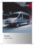
2008 Sprinter
2008
OWNER’ S MANUAL
81-326-0899
First Edition
Printed in U.S.A.
Sprinter
VEHICLES SOLD IN CANADA
With respect to any Vehicles Sold in Canada, the name
Chrysler LLC shall be deemed to be deleted and the
name Chrysler Canada Inc. used in substitution therefor.
DRIVING AND ALCOHOL
Drunken driving is one of the most frequent causes of
accidents.
Your driving ability can be seriously impaired with blood
alcohol levels far below the legal minimum. If you are
drinking, don’t drive. Ride with a designated non-drinking
driver, call a cab, a friend, or use public transportation.
WARNING!
This manual illustrates and describes the operation of
features and equipment that are either standard or optional on this vehicle. This manual may also include a
description of features and equipment that are no longer
available or were not ordered on this vehicle. Please
disregard any features and equipment described in this
manual that are not on this vehicle.
Chrysler LLC reserves the right to make changes in
design and specifications, and/or make additions to or
improvements to its products without imposing any
obligation upon itself to install them on products previously manufactured.
Driving after drinking can lead to an accident. Your
perceptions are less sharp, your reflexes are slower,
and your judgment is impaired when you have been
drinking. Never drink and then drive.
Copyright © 2007 Chrysler LLC
nf_BA.book Page 1 Friday, January 25, 2008 3:53 PM
Thank you for choosing the new
Sprinter Vehicle.
Before your first journey, please familiarize yourself with your vehicle and how it
operates, as well as its driving, control
and convenience functions.
Before you drive off, read these Operating Instructions. This will help you get
the most out of your vehicle and avoid
endangering yourself and others.
Since the scope of delivery is based on
the sales order, your vehicle’s equipment may differ from some descriptions
and illustrations. Items of optional
equipment are also described in these
Operating Instructions, should you require a description of the way they work.
Country-specific vehicle equipment, limited availability of items of special equipment or different product labeling is
possible in some countries.
vehicle. For this reason, you should always keep them in the vehicle and pass
them on to the new owner if you sell the
vehicle.
Chrysler Vans LLC reserves the right to
introduce changes in design, equipment
and technical features. You cannot,
therefore, base any claims on the data,
illustrations or descriptions contained in
these Operating Instructions.
The technical documentation team at
Chrysler Vans LLC wishes you safe and
pleasant driving.
Your nearest authorized Sprinter Dealer
will be happy to assist you further if you
have any other questions.
The Operating Instructions, brief instructions, Sprinter Service Booklet, Owner’s
Warranty Information Book and equipment-related supplementary operating
instructions are considered part of the
nf_BA.book Page 2 Friday, January 25, 2008 3:53 PM
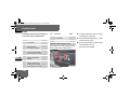
Symbols
Trademarks
*
Optional equipment
G
H
Warning
ESP® is a registered trademark of
Chrysler Vans LLC.
!
Caution
i
Tip
Action required
Sequence of actions (several )
Continuation symbol
page
Page reference
Environmental note
DisplayDisplay in the multifunction
display
nf_BA.book Page 3 Friday, January 25, 2008 3:53 PM
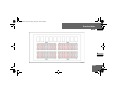
Contents
Introduction ............................5
1
At a glance ............................17
2
Safety .....................................33
3
Controls in detail ..................81
4
Operation ............................301
5
Practical hints ....................429
6
*Technical data .................599
Index............................................. 637
3
nf_BA.book Page 4 Friday, January 25, 2008 3:53 PM
nf_BA.book Page 5 Friday, January 25, 2008 3:53 PM
Introduction
Environmental protection
Environmental protection
Environmental note
Introduction
H
Chrysler’s declared policy is one of comprehensive environmental protection.
The objectives are for the natural resources which form the basis of our existence
on this planet to be used sparingly and in
a manner which takes the requirements
of both nature and humanity into account.
You too can contribute to environmental
protection by operating your vehicle in an
environmentally-responsible manner.
Fuel consumption and engine, transmission, brake and tire wear depend on the
two following factors:
Operating conditions of your vehicle
Your personal driving style
You can influence both factors.
Observe the following notes:
Operating conditions
Avoid driving short distances as this
increases fuel consumption.
Make sure that the tire pressures are
always correct.
Do not carry any unnecessary weight
in/on the vehicle.
Keep an eye on the vehicle’s fuel consumption.
Remove roof racks once you no longer need them.
A regularly serviced vehicle will contribute to environmental protection.
You should therefore adhere to the
specified service intervals.
Always have maintenance work carried out at an authorized Sprinter
Dealer.
5
nf_BA.book Page 6 Friday, January 25, 2008 3:53 PM
Introduction
Environmental protection
Personal driving style
Do not depress the accelerator pedal
when starting the engine.
Do not warm up the engine when the
vehicle is stationary.
Adopt an anticipatory style of driving
and keep a sufficient distance from
other vehicles.
Avoid frequent, sudden acceleration.
Switch off the engine in stationary
traffic.
6
Environmental concerns and
recommendations
In this manual, whenever you see instructions to discard materials, you
should first attempt to reclaim and recycle them. To preserve our environment,
follow appropriate environmental rules
and regulations when disposing of materials.
nf_BA.book Page 7 Friday, January 25, 2008 3:53 PM
Introduction
Operating safety
Operating safety
Warning
G
Engine exhaust, some of its constituents,
and certain vehicle components contain
or emit chemicals known to the State of
California to cause cancer and birth defects or other reproductive harm.
In addition, certain fluids contained in vehicles, and certain products of component wear, contain chemicals known to
the State of California to cause cancer
and birth defects or other reproductive
harm.
Warning
G
Work carried out incorrectly on electronic
equipment and its software could cause
the equipment to stop working. The electronic systems are networked with each
other via interfaces. Tampering with the
electronic systems may also cause malfunctions in systems that have not been
modified. These malfunctions, however,
can jeopardize the operating safety of
your vehicle and therefore put your own
safety at considerable risk.
Warning (Continued)
G
Other work carried out incorrectly or
modifications to the vehicle could also
jeopardize operating safety.
Some safety systems only function while
the engine is running. Therefore, you
should not switch off the engine while
driving.
Continued
7
nf_BA.book Page 8 Friday, January 25, 2008 3:53 PM
Introduction
Operating safety
Warning
G
Always have maintenance work carried
out at an authorized Sprinter Dealer which
has the necessary specialist knowledge
and tools to carry out the work required.
The manufacturer recommends that you
use an authorized Sprinter Dealer for this
purpose.
In particular, work relevant to safety or on
safety-related systems must be carried
out at an authorized Sprinter Dealer.
Warning
G
A heavy impact to the underbody, tires or
wheels, for example when bottoming out
on rough terrain or driving over an obstacle at high speed, could damage your vehicle. This also applies to vehicles
equipped with underbody protection.
In this case, have your vehicle checked at
an authorized Sprinter Dealer which has
the necessary specialist knowledge and
tools to carry out the work required. The
manufacturer recommends that you use
an authorized Sprinter Dealer for this purpose.
Continued
8
Warning (Continued)
G
In particular, work relevant to safety or on
safety-related systems must be carried
out at an authorized Sprinter Dealer.
nf_BA.book Page 9 Friday, January 25, 2008 3:53 PM
Introduction
Operating safety
Service and warranty information
The manufacturer warrants to the original and each subsequent owner of a
Mercedes-Benz heavy-duty on highway
diesel engine that:
(1) the engine was designed, built and
equipped so as to conform at the
time of sale with the applicable regulations adopted by the Federal Environmental Protection Agency, and
(2) the emission control system of such
engine is free from defects in materials and workmanship which would
cause it not to conform with those
regulations for a period of use of five
years or 100000 miles (160000 km)
or 3000 hours of engine operation,
whichever occurs first.
The Owner’s Warranty Information Book
contains detailed information about the
warranties covering your Sprinter Vehicle.
Registering your vehicle
The manufacturer may instruct its authorized Sprinter Dealer to carry out
technical inspections on certain vehicles
to improve their quality or safety.
thorized Sprinter Dealer, there is a
possibility that your vehicle has not been
registered in your name with the manufacturer. The manufacturer will only be
able to inform you about vehicle inspections if the manufacturer is in possession of your registration data.
It is advisable to have your vehicle registered at an authorized Sprinter Dealer.
Inform the manufacturer as soon as possible if your address has changed or
there has been a change of vehicle owner.
If you did not purchase your vehicle from
an authorized dealership and your vehicle has not yet been inspected at an au-
9
nf_BA.book Page 10 Friday, January 25, 2008 3:53 PM
Introduction
Operating safety
Digital speedometer and total
distance recorder
Do not allow the electronically stored total distance covered by your vehicle to
be modified as a result of tampering with
the electronics system.
This type of modification or failing to inform the buyer when selling the vehicle
could constitute an offense punishable
by law, depending on the country concerned.
10
Modifying the engine power output
Having the engine power output of your
vehicle increased by tampering with the
electronic engine management system
will invalidate the vehicle’s general operating permit and insurance coverage, as
well as your warranty and warranty entitlement.
Modifications to the output of the engine
must be reported to the insurance provider and require the vehicle to be recertified. The tires, chassis, brake and
cooling systems must be adapted to the
increased engine power output.
Tampering with the electronic engine
management system modifies emission
values and it will not be possible to guarantee the operating safety of the engine
in every case. Increases in performance
may lead to malfunctions and consequential damage to other assemblies.
If you sell the vehicle, failing to inform
the buyer of the modified engine power
output could constitute an offense punishable by law, depending on the country
concerned.
nf_BA.book Page 11 Friday, January 25, 2008 3:53 PM
Introduction
Operating safety
Vehicle alterations
The manufacturer recommends the use
of genuine Sprinter parts and conversion
parts as well as accessories that have
been expressly approved for your vehicle model ( page 600).
These parts have been subjected to special tests in order to determine their
safety, reliability and suitability.
Body builder guideline
If you intend on making any alterations
to the vehicle, we strongly recommend
that you select one of the following options in order to obtain all necessary information:
Contact the authorized Sprinter
Dealer nearest you to obtain a copy
of the Sprinter Body Builder Guideline.
Call Chrysler Vans LLC at telephone
(800) 992-1997 to request a copy of
the Sprinter Body Builder Guideline
(there may be a charge).
Write to the following address and
order the Sprinter Body Builder
Guideline (there may be a charge).
Chrysler Vans LLC
P.O. Box 21-8004
Auburn Hills, MI 48321-8004
United States of America
11
nf_BA.book Page 12 Friday, January 25, 2008 3:53 PM
Introduction
Operating safety
Body builders and dealers who make any
modifications which may affect the final
certification of the engine, vehicle or
equipment assume the sole responsibility for the vehicle, including labeling and
documentation, affected by their modifications.
It is their responsibility to certify that the
altered vehicle conforms to all applicable standards and regulations affected
by the vehicle alteration or continues to
comply with the motor vehicle safety
standards and emissions regulations.
They are responsible for ensuring that
modifications or equipment installation
does not affect the safety of the vehicle.
12
Any modifications or alterations of the
Sprinter vehicle not in compliance with
the Sprinter Body Builder Guideline and
the Sprinter Operator’s Manual may seriously inhibit its roadworthiness and safety and may lead to an accident resulting
in serious personal injury or death.
The manufacturer is not responsible for
any final certification or claims regarding product liability, or warranty claims,
which result from any component, assembly, or system being altered, or
which cause non-compliance with any of
the emission control standards or motor
vehicle safety standards, or which would
otherwise cause the vehicle to be or become defective or unsafe.
Consult the Sprinter Body Builder Guideline and the Sprinter Operator’s Manual
prior to initiating any alterations or modifications.
The manufacturer does not assume the
responsibility as the final stage manufacturer or the consequential product liability.
Warning
G
nf_BA.book Page 13 Friday, January 25, 2008 3:53 PM
Introduction
Operating safety
Stickers and warning labels
Correct use
Warning
G
Be sure to read the Operating Instructions.
Otherwise, you may not be aware of certain
risks and could injure yourself or others.
Observe the following information when
using your vehicle:
The safety notes in this manual
The “Technical data” section in this
manual
Traffic rules and regulations
Motor vehicle laws and safety standards
Warning
Problems with your vehicle
G
Various warning labels are affixed to your
vehicle. These warning labels are intended to make you and others aware of various risks. You should not remove any of
these warning labels unless explicitly instructed to do so by information on the label itself. Removal of any of these labels
may cause you and others to be unaware
of certain risks which may result in an accident and/or personal injury.
If you should experience a problem with
your vehicle, particularly one that you
believe may affect its safe operation, we
urge you to immediately contact an authorized Sprinter Dealer to have the
problem diagnosed and corrected if required.
If the matter is not handled to your satisfaction, please discuss the problem
with the Sprinter Dealer management,
or if necessary contact us at the following address.
13
nf_BA.book Page 14 Friday, January 25, 2008 3:53 PM
Introduction
Operating safety
In the USA:
In Canada:
Chrysler Vans LLC Customer Center
P.O. Box 21-8004
Auburn Hills, MI 48321-8001
United States of America
Telephone: 800-992-1997
Chrysler Canada, Inc. Customer Center
P.O. Box 1621
Windsor, Ontario N9A 4H6
Telephone: (800) 465-2001
14
nf_BA.book Page 15 Friday, January 25, 2008 3:53 PM
Introduction
REPORTING SAFETY DEFECTS
REPORTING SAFETY DEFECTS
In the 50 United States and Washington D.C.: If you believe that your vehicle has a defect, which could cause a crash or cause
injury or death, you should immediately inform the National Highway Traffic Safety Administration (NHTSA) in addition to notifying the manufacturer.
If the NHTSA receives similar complaints, it may open an investigation, and if it finds that a safety defect exists in a group of
vehicles, it may order a recall and remedy campaign. However, NHTSA cannot become involved in individual problems between
you, your dealer, and the manufacturer.
To contact NHTSA, you may either call the Auto Safety Hotline toll free at 1–888–327–4236 (TTY: 1-800-424-9153),
or go to http://www.safercar.gov; or write to: Administrator, NHTSA, 400 Seventh Street, SW., Washington DC 20590. You can
also obtain other information about motor vehicle safety from http://www.safercar.gov.
In Canada:
If you believe that your vehicle has a safety defect, you should contact the Customer Service Department immediately.
Canadian customers who wish to report a safety defect to the Canadian government should write to
Transport Canada, Motor Vehicle Defect Investigations and Recalls, 2780 Sheffield Road, Ottawa, Ontario K1B 3V9.
15
nf_BA.book Page 16 Friday, January 25, 2008 3:53 PM
Introduction
Information regarding electronic recording devices
Information regarding electronic recording devices
(Including notice pursuant to California Code § 9951)
Please note that your vehicle is equipped with devices that can record vehicle systems data.
This information helps, for example, to diagnose vehicle systems after a collision and to continuously improve vehicle safety.
Chrysler Vans LLC may access the information and share it with others
for safety research or vehicle diagnosis purposes
with the consent of the vehicle owner or lessee
in response to an official request by law enforcement or other government agency
for use in dispute resolution involving Chrysler Vans LL, its affiliates or sales/service organization and/or
as otherwise required or permitted by law.
16
nf_BA.book Page 17 Friday, January 25, 2008 3:53 PM
At a glance
At a glance
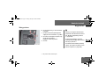
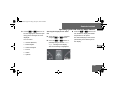
Cockpit............. 18
Instrument cluster............. 20 1
Steering wheel with buttons*............. 25
Center console............. 26
Overhead control panel*............. 27
Switch units............. 28
Door control panel............. 31
17
nf_BA.book Page 18 Friday, January 25, 2008 3:53 PM
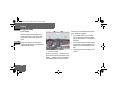
At a glance
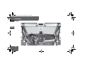
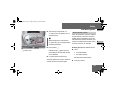
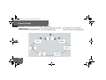
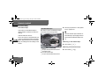
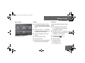
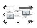
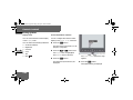
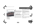
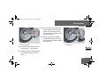
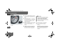
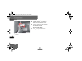
Cockpit
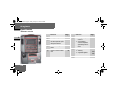
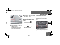
Cockpit
1
N68.10-2287-31
18
nf_BA.book Page 19 Friday, January 25, 2008 3:53 PM
At a glance
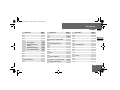
Cockpit
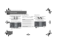
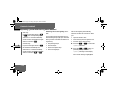
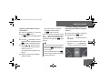
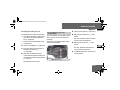
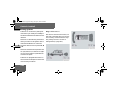
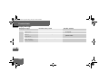
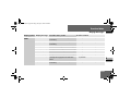
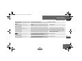
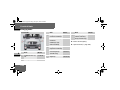
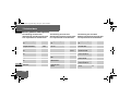
Function
1 Door control panel
2 Light switch
Page
31
4 Cruise control lever*
Page
20,
142
8 Storage compartment
135
131
210
9 Storage compartment
with interior lamp
Overhead control panel*
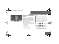
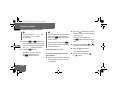
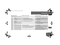
Function
e Jack and vehicle tool kit
515
f Glove box
288
g Center console
137
27
Page
26
h Selector lever (automatic
transmission)
185
j Ignition lock
111
a Rear-view mirror*
208
k Additional switch unit
249
b Rear view camera monitor*
261
l Handbrake
191
256
m Steering wheel adjustment
127
25
c Warning display for Parktronic system*
d Opens/closes the righthand side window
244
n Hood lock release
318
212
5 Horn
6 Steering wheel without/
with* buttons
7 Instrument cluster
130
3 Combination switch
Turn signals
High-beam headlamps
Windshield wipers
Rear window wiper*
Function
o Additional switch unit
29
29
19
1
nf_BA.book Page 20 Friday, January 25, 2008 3:53 PM
At a glance
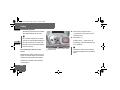
Instrument cluster
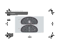
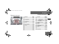
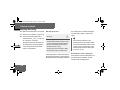
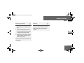
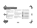
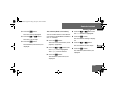
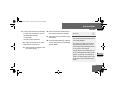
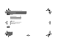
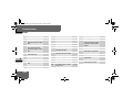
Instrument cluster
1
20
nf_BA.book Page 21 Friday, January 25, 2008 3:53 PM
At a glance
Instrument cluster
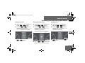
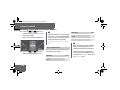
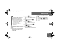
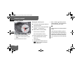
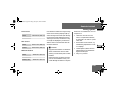
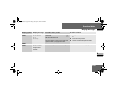
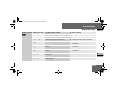
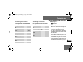
Function
1 Instrument cluster on vehicles without steering
wheel buttons
142
2 Instrument cluster on vehicles with steering wheel
buttons*
142
3
On vehicles without
steering wheel buttons:
Changes the
standard display
Selects menus
Function
Page
4
On vehicles with
steering wheel buttons*:
Function
Page
8 Display on vehicles without steering wheel buttons
148
1
Checks the engine
oil level
157
9 Display on vehicles with
steering wheel buttons*
157
Reset button
142
a Tachometer with:
145
6 Speedometer with:
145
5
148
Page
Indicator and warning
lamps
22
7 Indicator and warning
lamps
22
Indicator and warning
lamps
b
Instrument lighting
brighter/
dimmer
22
144
21
nf_BA.book Page 22 Friday, January 25, 2008 3:53 PM
At a glance
Instrument cluster
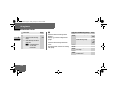
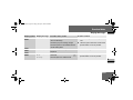
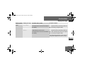
Function
1
c Fuel gauge with:
Reserve fuel warning
lamp
Fuel filler flap location
indicator
Ö: Fuel filler flap is
on the lefthand side
22
Page
145
475
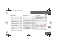
i
Indicator and Warning Lamps
Vehicles without steering wheel
buttons:
Display 8 contains a digital fuel
gauge.
v ESP warning lamp
Vehicles with steering wheel buttons*:
The tachometer contains an analog
fuel gauge.
®
ASR warning lamp
Page
72
468
73
74
465
/ Coolant level too low
474
D Coolant temperature
too high
475
1 Restraint systems
malfunction
469
nf_BA.book Page 23 Friday, January 25, 2008 3:53 PM
At a glance
Instrument cluster
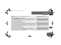
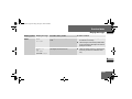
Indicator and Warning Lamps
Page
Brake fluid level too
low
463
EBV malfunction
462
Malfunction in trailer's
brake booster
464
N Engine oil level warning as47
1
± Engine diagnostic
indicator lamp
477
q Pre-glow system, diesel engine only
186
476
Turn signal, left
135
Indicator and warning lamps Page
X Combination low tire
pressure/TPMS malfunction telltale, USA
only
478
Low tire pressure telltale, Canada only
478
J Windshield washer/
headlamp cleaning system* washer fluid level
too low
Door open
2 Brake pads/linings
worn
482
Indicator and warning lamps Page
Turn signal, right
135
- ABS malfunction
466
k ASR malfunction
465
BAS malfunction
465
# ESP® malfunction
468
‰ Air cleaner dirty
477
A Reserve fuel
475
Fuel filler flap open
476
483
470
23
1
nf_BA.book Page 24 Friday, January 25, 2008 3:53 PM
At a glance
Instrument cluster
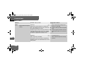
Indicator and warning lamps Page
Water in the fuel
1
482
# Battery charge malfunction
469
. Defective bulb
483
Handbrake applied
191
B Low-beam headlamps
on
131
™ Operating speed governor on*
273
A High-beam headlamps
on
131
< Seat belt reminder
482
24
i
Vehicles with steering wheel buttons:
Corresponding messages may also
be shown in display 9
( page 157).
nf_BA.book Page 25 Friday, January 25, 2008 3:53 PM
At a glance
Steering wheel with buttons*
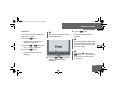
Steering wheel with buttons*
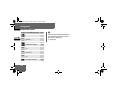
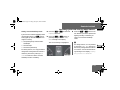
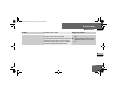
Function
1 Display
Page
151
t Ends a call/
rejects an incoming call
151
4 To jump from one menu
to another
Controlling the operating system
2 To select a submenu or
adjust the volume
N46.10-2074-31
Function
+ Up/increases the
volume
è Forward
- Down/decreases
the volume
5 To jump from one
submenu to another
3 Telephone* functions
s Accepts a call/
starts dialing
Page
1
151
· Backward
178
151
j Forward
k Backward
25
nf_BA.book Page 26 Friday, January 25, 2008 3:53 PM
At a glance
Center console
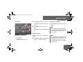
Center console
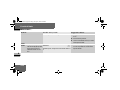
Function
1
Page
1
Storage compartment
2
Radio* or COMAND*,
see the separate operating instructions
3
Air-conditioning control
panel
218
4
Center console switch
unit
28
N68.10-2288-31
290
Function
5
Storage compartment or
CD changer*,
see the separate
operating instructions
6
Cup holder with
Ashtray
Cigarette lighter
291
12 V socket
297
7
26
Page
294
295
nf_BA.book Page 27 Friday, January 25, 2008 3:53 PM
At a glance
Overhead control panel*
Overhead control panel*
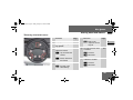
Function
Page
1 Hands-free microphone
for telephone*
2 Switches the right-hand
reading lamp
on/off
137
3 Switches the automatic
interior lighting
on/off
137
Function
Page
4 Eyeglass
compartment or
Anti-theft alarm system (ATA)*
290
5 Switches the interior
lighting
on/off
137
6 Switches the left-hand
reading lamp
on/off
137
7 Opens/closes the sliding sunroof*
245
77
27
1
nf_BA.book Page 28 Friday, January 25, 2008 3:53 PM
At a glance
Switch units
Switch units
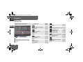
Center console switch unit
Function
1
N54.25-2915-31
&
i
The number of switches may vary,
depending on the vehicle’s equipment.
28
Page
Opens/closes the lefthand electric sliding
door*
92
Switches the left/right
seat heating*
on/off
122
Switches the rear window heating*
on/off
P Switches the windshield
heating*
on/off
Activates/deactivates
ASR
74
Switches the hazard
warning flashers on/off
136
Central locking
Interior/rear
compartment
104
253
214
! Switches the Parktronic
system (PTS)*
on/off
92
213
Opens/closes the righthand electric sliding
door*
nf_BA.book Page 29 Friday, January 25, 2008 3:53 PM
At a glance
Switch units
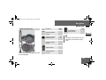
Additional switch units
N54.25-2913-31
Switch unit between the light switch and
the steering wheel
Function
Ventilates the load
compartment,
air in/air out*
Page
³ Switches the heater
booster function*
on/off
234
ö Switches auxiliary
³ heating*on/off
238
247
1
Switches the heater
booster function*
on/off
234
Adjusts the working
engine speed*
275
Switches the operating
speed governor*
on/off
273
i
The layout of the switches may vary,
depending on the vehicle’s equipment.
29
nf_BA.book Page 30 Friday, January 25, 2008 3:53 PM
At a glance
Switch units
Function
Switches the rear-compartment convenience
interior lighting*
on/off
1
Page
140
i
N54.25-2912-31
Switch unit between the steering wheel
and the ignition lock
30
The layout of the switches may vary,
depending on the vehicle’s equipment.
nf_BA.book Page 31 Friday, January 25, 2008 3:53 PM
At a glance
Door control panel
Door control panel
Function
N54.25-2914-31
Page
1 Adjusts the exterior
mirrors*
208
2 Selects an exterior
mirror*
208
3 Opens/closes the lefthand side window
244
4 Opens/closes the righthand side window
244
1
31
nf_BA.book Page 32 Friday, January 25, 2008 3:53 PM
nf_BA.book Page 33 Friday, January 25, 2008 3:53 PM
Safety
Safety
Occupant safety............. 34
Emergency exit............. 66
Driving safety systems............. 69
Anti-theft systems............. 77
33
2
nf_BA.book Page 34 Friday, January 25, 2008 3:53 PM
Safety
Occupant safety
Occupant safety
Restraint systems
2
This section contains all the most important information about the restraint systems in your vehicle. In an accident, your
vehicle collides with another object, e.g.
another vehicle. This may cause your vehicle to accelerate or decelerate extremely quickly. During this acceleration
or deceleration, the vehicle occupants
will be moved in the opposite direction
to the force of the impact. There is therefore the risk of vehicle occupants injuring themselves on the vehicle interior or
on parts of the vehicle. The purpose of
supplemental restraint systems, i.e.
34
principally the seat belts supplemented
by emergency tensioning retractors, belt
force limiters and airbags when necessary, is to minimize this risk of injury.
However, the seat belts and airbags cannot generally prevent injuries caused by
objects penetrating the vehicle from the
outside.
Additional protection is provided by:
SRS (Supplemental Restraint System), comprising:
The most important restraint systems
are:
the seat belts
restraint systems for children, since
they are the most effective means of
reducing the extent to which the occupants are moved in the event of an
accident
protection afforded to vehicle occupants
wearing a seat belt and is therefore only
to be considered as an additional restraint system to the seat belt. Airbags
do not in any way relieve any vehicle occupants of the need to wear their seat
belt correctly at all times.
emergency tensioning retractors
belt force limiters
airbags
iAn airbag increases the degree of
nf_BA.book Page 35 Friday, January 25, 2008 3:53 PM
Safety
Occupant safety
This is partly because an airbag is
not activated in all accident situations because in some cases it would
not provide any additional protection
to that already afforded by a correctly fastened seat belt.
Furthermore, an activated airbag can
only provide increased protection if the
seat belt is being worn correctly, because:
the belt helps to hold the vehicle
occupant in the best position in relation to the airbag
the belt prevents the vehicle occupant from being propelled in the opposite direction to the force of impact,
e.g. in the event of a head-on collision, and is therefore better able to reduce the risk of injury
In accidents in which an airbag is
activated, the airbag will therefore
only offer an increase in the protection provided by the seat belt, i.e. additional protection, if the seat belt is
worn correctly.
Warning
G
Modifications to or work incorrectly carried out on a restraint system (seat belt
and seat belt anchorages, emergency
tensioning retractor, belt force limiter or
airbag) or its wiring, or tampering with
other networked electronic systems,
could cause the restraint systems to stop
working correctly.
Continued
35
2
nf_BA.book Page 36 Friday, January 25, 2008 3:53 PM
Safety
Occupant safety
Warning (Continued)
2
G
The airbags or emergency tensioning retractors could, for example, be activated
inadvertently or could fail in accidents in
which the deceleration force is sufficient
to trigger the airbag. For this reason, do
not modify the restraint systems. Do not
tamper with electronic components or
their software.
36
Airbags
Warning
Seat belts
G
Airbags do offer additional protection but
they are not a substitute for the seat
belts. To reduce the risk of serious or fatal
injuries, make sure that all occupants – in
particular, expectant mothers – wear
their seat belt correctly at all times, have
adopted a normal sitting position and that
the seat is positioned as upright as possible.
The most important restraint systems in
the vehicle are the seat belts and child
restraint systems. They are the most effective means of preventing vehicle occupants from moving towards the point
of impact and thus reducing the risk of
occupants hitting parts of the vehicle interior.
i
In many countries there are regulations concerning the use of seat
belts and child restraint systems.
nf_BA.book Page 37 Friday, January 25, 2008 3:53 PM
Safety
Occupant safety
G
Warning
Warning (Continued)
G
A seat belt that is worn incorrectly or not at
all, or that is not correctly engaged in the
seat belt buckle, cannot perform its intended
protective function. In certain circumstances, you could be seriously or even fatally injured. Make sure, that all occupants – in
particular, expectant mothers – wear their
seat belt correctly at all times.
fits closely
You must make sure that the belt:
is pulled tight across the lap by pulling upwards on the shoulder belt
is routed as low as possible across your
pelvic area, for example across your hip
joints and not across your abdomen
Continued
is not twisted
is routed across the middle of your shoulder
is not routed across your neck or under
your arm
Do not secure any objects with a seat belt
if it is being used by one of the vehicle’s
occupants.
Warning (Continued)
G
Avoid wearing bulky clothing, for example
a winter coat.
Do not route the belt strap over sharp or
fragile objects, especially if these are located in or on your clothing, for example
eyeglasses, pens or keys. The belt strap
could otherwise tear in the event of an accident and you or other vehicle occupants
could be injured as a result.
Only one person may use each seat belt at
any one time.
Continued
37
2
nf_BA.book Page 38 Friday, January 25, 2008 3:53 PM
Safety
Occupant safety
Warning (Continued)
2
G
A child must never be carried sitting on
the lap of a vehicle occupant. It would not
be possible to restrain the child, and the
child and other vehicle occupants could
be seriously or fatally injured in the event
of abrupt braking or an accident.
Persons less than 1.50 m tall or children
under 12 years of age cannot wear their
seat belt properly. They therefore require
additional restraint systems on suitable
vehicle seats for protection in an accident. Always observe the installation instructions issued by the manufacturer of
the child restraint systems.
38
Warning
G
The seat belt only provides its intended
degree of protection if the seat backrest
is positioned as vertically as possible, allowing the occupant to sit upright. Avoid
seat positions that do not allow the seat
belt to be routed correctly. Therefore, position the backrest as vertically as possible. Never drive with the backrest tilted
too far back. You could otherwise be seriously or even fatally injured in the event of
an accident or abrupt braking.
G
Warning
The seat belt cannot perform its protective function correctly if the seat belt
strap or buckle are dirty or damaged. You
should therefore keep the belt strap and
buckle clean, as otherwise the belt latch
plate may not be able to engage correctly.
Check regularly that the seat belts:
are not damaged
are not routed over sharp edges
are not trapped
Continued
nf_BA.book Page 39 Friday, January 25, 2008 3:53 PM
Safety
Occupant safety
Warning (Continued)
G
The belt strap could otherwise tear in the
event of an accident. You or others could
be seriously or fatally injured.
Always have seats belts that are damaged
or have been subjected to a heavy load in
an accident replaced, and their anchorages checked, at a qualified specialist workshop which has the necessary specialist
knowledge and tools to carry out the work
required.
Continued
Warning (Continued)
G
Wearing seat belts
The manufacturer recommends that you
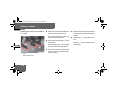
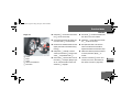
use an authorized Sprinter Dealer for this
purpose. In particular, work relevant to
safety or on safety-related systems must
be carried out at a qualified specialist
workshop .
2
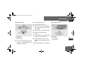
For safety reasons, the manufacturer recommends that you only use seat belts
that have been specially approved for
your vehicle by the manufacturer.
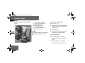
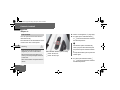
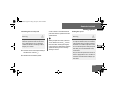
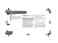
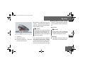
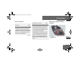
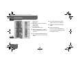
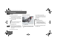
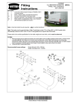
1
2
3
4
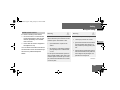
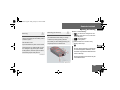
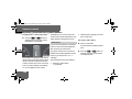
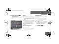
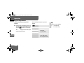
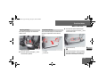
Belt sash guide ( page 40)
Belt latch plate
Release button
Buckle
39
nf_BA.book Page 40 Friday, January 25, 2008 3:53 PM
Safety
Occupant safety
Pull the belt smoothly from the seat
belt reel holder.
Route the belt over your shoulder.
2
Click belt latch plate 2 into buckle
4.
Adjust the belt to the correct height
if necessary.
Pull the shoulder section of the belt
upwards to tighten the belt against
your body if necessary.
Adjusting the belt height
Warning
G
Only adjust the belt height when the vehicle is stationary and the handbrake is applied.
You could otherwise lose control of the
vehicle as a result of the seat adjusting
movement and thereby endanger yourself
and others.
You can adjust the belt height for the following seats:
Driver’s seat
Outer passenger’s seat
40
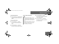
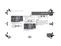
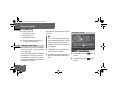
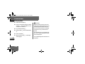
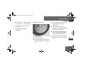
Adjust the belt height in such a way that
the shoulder belt is routed over the middle of the shoulder.
Belt sash guide with height adjustment
5 Release button
nf_BA.book Page 41 Friday, January 25, 2008 3:53 PM
Safety
Occupant safety
To raise the belt height: slide belt
sash guide 1 upward.
Belt sash guide 1 engages in various positions.
To lower the belt height: press and
hold release button 5.
Slide belt sash guide 1 to the desired height.
Let go of release button 5 and
make sure that belt sash guide 1
engages.
SRS (Supplemental Restraint
System)
The SRS (Supplemental Restraint System) may consist of the following components, depending on the equipment
level:
1 warning lamp
Emergency tensioning retractors
Belt force limiters
Airbag system with:
1 warning lamp
The SRS performs a self-test at regular
intervals when the ignition is switched
on and while the engine is running. Malfunctions can therefore be detected in
good time.
The 1 warning lamp in the instrument cluster ( page 20) comes on for
approximately 4 seconds when you
switch on the ignition.
Airbag control unit
Airbags
41
2
nf_BA.book Page 42 Friday, January 25, 2008 3:53 PM
Safety
Occupant safety
Warning
G
A malfunction has occurred if the 1
warning lamp:
2
does not come on when you switch on the
ignition
does not go out after approximately 4 seconds
lights up again
Individual systems may be activated unintentionally or may not be triggered in the
event of an accident with a high rate of vehicle deceleration.
Continued
42
Warning (Continued)
G
In this case, have the SRS system
checked and repaired immediately at a
qualified specialist workshop which has
the necessary specialist knowledge and
tools to carry out the work required.
The manufacturer recommends that you
use an authorized Sprinter Dealer for this
purpose. In particular, work relevant to
safety or on safety-related systems must
be carried out at a qualified specialist
workshop.
Activation of emergency tensioning
retractors, belt force limiters and airbags
In the event of a collision, the sensor in
the airbag control unit evaluates important physical data, such as duration, direction and rate of vehicle deceleration
or acceleration. Based on the evaluation
of this data and depending on the vehicle’s rate of longitudinal deceleration in
a collision, in the first stage, the airbag
control unit pre-emptively triggers the
emergency tensioning retractors.
nf_BA.book Page 43 Friday, January 25, 2008 3:53 PM
Safety
Occupant safety
The front airbags are not triggered unless a second activation threshold is exceeded, i.e. if there is a greater rate of
vehicle deceleration in a longitudinal direction.
Criteria for triggering of emergency
tensioning retractors and airbags
To determine whether it is necessary to
trigger an emergency tensioning retractor or airbag, the airbag control unit evaluates the duration and direction of
deceleration or acceleration during the
initial phase of the collision.
The emergency tensioning retractor and
airbag activation thresholds are variable
and are adapted to the rate of the vehicle deceleration. This process is preemptive in nature as the airbag must be
deployed during – and not at the end of
– the collision.
i
Airbags are not triggered in all types of
accident. They are actually controlled
by complex sensor technology and evaluation logic. This process is pre-emptive
in nature as airbag deployment must
take place during the impact and must
be adapted to provide calculated, additional protection for the vehicle occupants. Not all airbags are triggered in an
accident.
The various airbag systems work independently of each other. However, all
systems depend on the type (head-on
or side impact) and severity (in particular vehicle deceleration or acceleration)
of accident determined in the initial
phase of the accident.
43
2
nf_BA.book Page 44 Friday, January 25, 2008 3:53 PM
Safety
Occupant safety
2
Vehicle deceleration or acceleration and
the direction of the force are essentially
determined by:
the distribution of the force during
the impact
the collision angle
the deformation characteristics of
the vehicle
the composition of the object involved in the collision, for example
the other vehicle
Factors that cannot be seen or measured until after the collision are not
used to determine whether the airbag
should be triggered and are not decisive
for this.
44
The vehicle may be substantially deformed
without an airbag being triggered, for example if only relatively easily-deformable
vehicle parts such as the hood or fenders
are affected by the collision and the required deceleration threshold is not
reached. On the other hand, airbags may
be triggered even though the vehicle only
displays minor deformation, if, for example, rigid vehicle parts such as a longitudinal member are affected by the impact,
thus causing vehicle deceleration to exceed the pre-determined threshold.
Emergency tensioning retractors,
belt force limiters
If the vehicle is equipped with a driver’s
airbag, the driver’s and the passenger’s
seat belts are equipped with emergency
tensioning retractors.
A belt force limiter additionally installed
in the seat belt reduces the load exerted
by the seat belt on the occupant when it
is triggered.
Emergency tensioning retractors tension the seat belts in an accident, pulling
them close against the body.
nf_BA.book Page 45 Friday, January 25, 2008 3:53 PM
Safety
Occupant safety
i
Emergency tensioning retractors do
not correct:
incorrect sitting positions
incorrectly worn seat belts
Emergency tensioning retractors do
not pull occupants back towards the
backrest.
When the ignition is on, the emergency
tensioning retractor is activated:
only if the restraint systems are operational (the 1-warning lamp
comes on for approximately 4 seconds after the ignition is switched
on.) ( page 41).
in the event of a head-on or rear-end
collision, if there is a high rate of vehicle acceleration or deceleration in
the initial stages of a collision
in the event of a side impact, if the
vehicle suddenly decelerates or accelerates in a lateral direction at the
initial stage of the impact and the vehicle is equipped with thorax/
sidebags and/or windowbags.
If the emergency tensioning retractors
are triggered, you will hear a bang that is
generally harmless to your hearing. A
small amount of powder may also be released. The 1 warning lamp lights
up.
Warning
G
If the emergency tensioning retractors
have been triggered, have them replaced
at a qualified specialist workshop which
has the necessary specialist knowledge
and tools to carry out the work required.
Continued
45
2
nf_BA.book Page 46 Friday, January 25, 2008 3:53 PM
Safety
Occupant safety
Warning (Continued)
2
G
The manufacturer recommends that you
use an authorized Sprinter Dealer for this
purpose. In particular, work relevant to
safety or on safety-related systems must
be carried out at a qualified specialist
workshop.
Observe the safety regulations when disposing of emergency tensioning retractors. You can see a copy of these
regulations at any authorized Sprinter
Dealer.
Airbag system
Warning
Warning (Continued)
G
To reduce the risk of serious or fatal
injuries in the event of an accident
with a high rate of deceleration, for
example due to an airbag inflating
within milliseconds, or due to sudden
braking, please observe the following
points:
Continued
G
All vehicle occupants must select a seat
position in which they can wear their seat
belt correctly and which is as far back
from the airbag as possible. The seat position of the driver must be such that the
vehicle can be driven safely. The distance
from the driver’s seat to the pedals must
be such that the driver can fully depress
the pedals. The distance between the
driver’s chest and the center of the airbag
cover must be more than 25 cm. The driver’s arms should be slightly bent when
holding the steering wheel.
Continued
46
nf_BA.book Page 47 Friday, January 25, 2008 3:53 PM
Safety
Occupant safety
Warning (Continued)
G
Warning (Continued)
G
Warning (Continued)
G
Vehicle occupants should wear their
seat belt correctly at all times and
lean back against the backrest, which
should be positioned as upright as
possible. The head restraints should
support the back of the head at about
eye level.
On vehicles with a passenger’s airbag, it is not permitted to secure a
rearward-facing child restraint system to the passenger’s seat
( page 56). Children in a rearwardfacing child restraint system must be
secured on a suitable rear seat.
Only hold the steering wheel by the
outer rim. This allows the airbag to inflate fully. If you hold the inside of the
steering wheel, you could be injured if
the airbag were to be triggered.
Move the passenger’s seat as far to
the rear as possible, especially if a
child is secured in a restraint system
installed on this seat.
Do not lean forward, for example over
the padded boss of the steering
wheel, especially when the vehicle is
in motion.
Do not lean on the doors from inside
the vehicle.
Continued
Continued
Do not put your feet on the dashboard.
Make sure that no persons, animals
or objects are present between the
vehicle occupants and the deployment range of the airbags.
Continued
47
2
nf_BA.book Page 48 Friday, January 25, 2008 3:53 PM
Safety
Occupant safety
Warning (Continued)
2
G
Do not cover the padded boss of the
steering wheel, the passenger’s airbag cover, the windowbag cover or
the thorax/sidebag cover with film or
other material. Do not affix any badges or stickers to these areas.
Do not hang any hard objects, for example coat hangers, on the grab handles or coat hooks.
Do not place any items in the storage
compartment above the passenger’s
airbag if they protrude from the compartment. The passenger’s airbag
must be able to inflate unimpeded.
The risk of injuries from an airbag cannot
be entirely ruled out due to the high speed
at which the airbag is required to inflate.
48
Your vehicle is equipped with the following airbags, depending on the equipment version:
Driver’s front airbag, located in the
steering wheel
Passenger’s front airbag, located
above the glove box
Thorax sidebags* in the outer sides
of the driver’s seat and the passenger’s individual seat
Windowbags* in the side of the roof
frame between the A and B-pillars
Each airbag's cover is marked with the
letters "SRS/AIRBAG" or "AIRBAG".
How airbags work
An airbag inflates within milliseconds.
The 1 warning lamp in the instrument cluster comes on.
i
If the airbags are triggered, you will
hear a bang and a small amount of
dust may also be released. The bang
will not damage your hearing and the
dust does not constitute a health
hazard.
Airbag inflation slows down and restricts
the movement of the vehicle occupant.
nf_BA.book Page 49 Friday, January 25, 2008 3:53 PM
Safety
Occupant safety
When the vehicle occupant makes contact with the airbag, hot gas flows out of
the inflated airbag. This reduces the load
on the head and upper body of the vehicle occupant. The airbag is therefore in a
deflated state after an accident.
Warning
G
After an airbag has been triggered:
airbag parts are hot – do not touch
them, otherwise you could be burnt
the airbags must be replaced at a
qualified specialist workshop which
has the necessary specialist knowledge and tools to carry out the work
required. The manufacturer recommends that you use an authorized
Sprinter Dealer for this purpose.
In particular, work relevant to safety
or on safety-related systems must be
carried out at a qualified specialist
workshop.
Warning
G
A small amount of fine powder is released as
an airbag inflates. This powder does not constitute a health hazard, nor does it imply that
fire has broken out in the vehicle. This powder could cause short-term breathing difficulties for persons suffering from asthma or
other respiratory conditions. To avoid these
breathing difficulties, you should either:
leave the vehicle immediately, if it is
possible to do so safely
or
open the window to allow fresh air to
enter
49
2
nf_BA.book Page 50 Friday, January 25, 2008 3:53 PM
Safety
Occupant safety
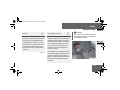
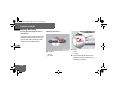
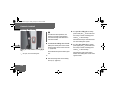
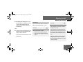
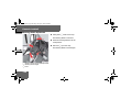
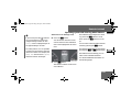
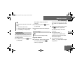
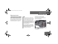
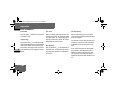
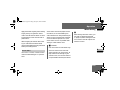
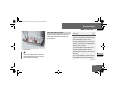
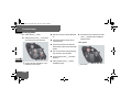
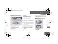
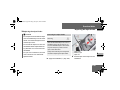
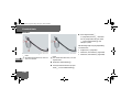
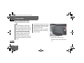
Front airbags
The front airbags are designed to increase protection to the driver’s and
passenger’s/passengers' head and
chest.
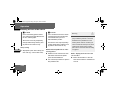
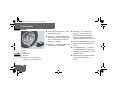
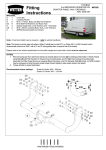
2 The driver’s airbag is located in the
N91.60-2140-31
steering wheel housing; the passenger’s
is above the glove box.
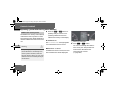
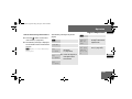
1 Driver’s airbag
2 Passenger’s airbag
Driver’s front airbag 1 inflates in front
of the steering wheel; passenger’s front
airbag 2 inflates in front of and above
the glove box and the center console.
50
The driver’s front airbag and passenger’s
front airbag are triggered:
in the initial stages of an accident
with a high rate of vehicle acceleration or deceleration in a longitudinal
direction
if the system determines that airbag
deployment can offer additional protection to that provided by the seat
belt
independently of other airbags in the
vehicle
nf_BA.book Page 51 Friday, January 25, 2008 3:53 PM
Safety
Occupant safety
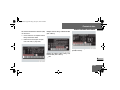
Thorax sidebags*
Warning
Warning
G
For safety reasons, the manufacturer recommends that you use seat covers that
have been tested for Sprinter vehicles
and that have a seam for thorax/
sidebags. A thorax/sidebag may otherwise not inflate correctly and could fail to
provide the intended degree of protection
in the event of a collision. You can obtain
these covers from an authorized Sprinter
Dealer, for example.
G
To reduce the risk of injury to occupants
if a thorax/sidebag is triggered, make
sure that:
no persons, animals or objects are
present between the vehicle occupants and the thorax/sidebag deployment range
no accessories, for example cup holders, are secured to the doors
only light items of clothing are hung
from the coat hooks in the vehicle
there are no heavy or sharp objects in
the pockets of items of clothing
Warning
G
Observe the following to reduce the risk of
serious or fatal injury if the thorax/
sidebag is triggered:
Vehicle occupants – in particular, children – must never lean their head
against the area of the window in
which the thorax/sidebag inflates.
Vehicle occupants must wear their
seat belt correctly at all times and
lean back against the backrest, which
should be positioned as upright as
possible.
Always secure children who are less
than 5 ft (1.50 m) tall or under
12 years of age in a suitable child restraint system.
51
2
nf_BA.book Page 52 Friday, January 25, 2008 3:53 PM
Safety
Occupant safety
on the side on which an impact occurs
if the system determines that airbag
deployment can offer additional protection to that provided by the seat
belt
independently of the front airbags
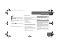
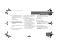
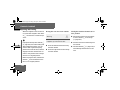
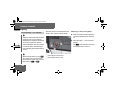
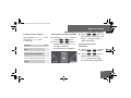
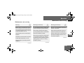
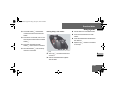
The purpose of the thorax/sidebags is
to increase the level of protection for the
thorax (but not the head, neck and arms)
of the occupants on the side of the vehicle on which the impact occurs.
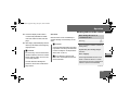
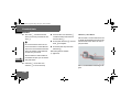
2 The thorax/sidebags are installed in the
outer sides of the backrests on the driver’s seat and the passenger’s individual
seat
1 Thorax sidebag
The thorax sidebags are triggered:
in the initial stages of an accident
with a high rate of vehicle acceleration or deceleration in a lateral direction, for example in the event of a
side impact
52
In the event of an accident, the thorax
sidebag next to the outer seat side inflates between the door and the chest
area of the occupant.
nf_BA.book Page 53 Friday, January 25, 2008 3:53 PM
Safety
Occupant safety
i
You will find additional information
about airbag deployment on
( page 48).
You will find additional information
about the triggering of emergency
tensioning retractors and belt force
limiters on ( page 44).
Windowbags*
Warning
Warning
G
To ensure that windowbags can provide
the intended degree of protection when
deployed, make sure that no persons, animals or objects are present between the
vehicle occupants and the deployment
range of the windowbags.
G
Observe the following to reduce the risk
of serious or fatal injury if the windowbag
is triggered:
Vehicle occupants – in particular,
children – must never lean their head
against the area of the window in
which the windowbag inflates.
Vehicle occupants must wear their
seat belt correctly at all times.
Always secure children who are less
than 5 ft (1.50 m) tall or under
12 years of age in a suitable child restraint system.
53
2
nf_BA.book Page 54 Friday, January 25, 2008 3:53 PM
Safety
Occupant safety
on the side on which an impact occurs
independently of the front airbags
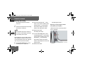
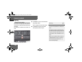
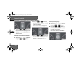
The windowbags are designed to increase protection to the head (but not to
the chest or arms) of the vehicle occupants on the side on which the impact
occurs.
i
You will find additional information
about airbag deployment on
( page 48).
2 The relevant windowbag is installed in
the side of the roof frame behind the
trim panel between the A and B-pillar.
1 Windowbag
The windowbags are triggered:
in the initial stages of an accident
with a high rate of vehicle acceleration or deceleration in a lateral direction
54
You will find additional information
about the triggering of emergency
tensioning retractors and belt force
limiters on ( page 44).
nf_BA.book Page 55 Friday, January 25, 2008 3:53 PM
Safety
Occupant safety
Children in the vehicle
G
If a child is traveling in the vehicle:
secure the child in a child restraint
system appropriate to his/her age
and size, preferably on a suitable
seat in the rear
ensure that the child is strapped in
throughout the trip
Warning
You can obtain child seats and information about the correct child restraint system from any authorized Sprinter
Dealer.
be seriously or even fatally injured by
prolonged exposure to extreme heat
or cold
Do not leave children unsupervised in the
vehicle even if they are secured in a child
restraint system. The children could:
injure themselves on parts of the
vehicle
Do not expose child restraint systems to
direct sunlight. Metallic parts of the child
restraint system could heat up, for example, and the child could burn him/herself
on the hot parts.
Warning
G
If the children open a door, they could:
cause injury to others as a result
get out of the vehicle and could either
injure themselves when doing so or
they could be injured by passing vehicles
sustain serious injuries if they were to
fall out of the vehicle, due in particular
to the height of the passenger compartment from the ground
Continued
55
2
nf_BA.book Page 56 Friday, January 25, 2008 3:53 PM
Safety
Occupant safety
Warning (Continued)
2
G
Do not carry heavy or hard objects inside
the vehicle or load compartment unless
they are secured. You will find further information under “Transporting”
( page 276) and “Features”
( page 287) in the “Controls in detail”
section.
An unsecured or incorrectly positioned load
increases the risk of injury to occupants, particularly children, in the event of:
sharp braking
a sudden change of direction
an accident
56
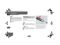
Child restraint systems
We recommend all infants and children
be properly restrained at all times while
the vehicle is in motion.
All lap-shoulder belts except the driver’s
seat belt have special seat belt retractors for secure fastening of child restraints.
To fasten a child restraint, follow child
restraint instructions for mounting. Then
pull the shoulder belt out completely
and let it retract. During seat belt retraction, a ratcheting sound can be heard to
indicate that the special seat belt retractor is activated. The belt is now locked.
Push down on child restraint to take up
any slack.
nf_BA.book Page 57 Friday, January 25, 2008 3:53 PM
Safety
Occupant safety
To deactivate, release seat belt buckle
and let seat belt retract completely. The
seat belt can again be used in the usual
manner.
Warning
G
Never release the seat belt buckle while
the vehicle is in motion, since the special
seat belt retractor will be deactivated.
Warning
G
Warning (Continued)
G
To reduce the risk of serious or fatal injury
to a child in the event of an accident,
sharp braking or a sudden change in direction:
It is not permitted to secure a child in the
passenger’s seat or the center position of
the front bench seat if the vehicle is
equipped with a passenger’s airbag.
Always secure children less than 5 ft
(1.50 m) tall or under 12 years of age
in a special child restraint system installed on a suitable vehicle seat,
since the seat belts are not designed
for this body size.
Only secure a rearward-facing child restraint system on a suitable rear seat.
Continued
Continued
57
2
nf_BA.book Page 58 Friday, January 25, 2008 3:53 PM
Safety
Occupant safety
Warning (Continued)
2
G
A child must never be carried sitting on
the lap of a vehicle occupant. It would not
be possible to restrain the child as a result
of the forces acting in the event of an accident, braking or abrupt changes in direction. The child would be thrown
against parts of the vehicle interior and be
seriously or fatally injured.
Vehicle occupants must wear their seat
belt correctly at all times.
Warning
G
If the child restraint system is not installed correctly on a suitable vehicle
seat, the child may not be restrained in
the event of an accident or sudden braking and may be seriously or fatally injured.
For this reason, always observe the installation instructions issued by the child restraint system manufacturer and the
intended use for the child restraint system when fitting it.
It is advisable to install the child restraint
system on one of the rear seats. The child
is generally better protected there.
Continued
58
Warning (Continued)
G
Do not place objects (for example a cushion) underneath the child restraint system. The entire base of the child restraint
system must be in contact with the seat
cushion at all times.
Child restraint systems must not be used
without the original cover. Replace damaged covers only with original covers.
On the rear seats, only use child restraint
systems recommended by the manufacturer.
nf_BA.book Page 59 Friday, January 25, 2008 3:53 PM
Safety
Occupant safety
Warning
G
If you no longer require the child restraint
system, remove it from the vehicle or secure it with the seat belt.
The restraint system could otherwise be
thrown through the vehicle interior in the
event of an accident.
Warning
G
A child secured in a child restraint system
could be seriously or fatally injured in the
event of an accident, braking or a sudden
change in direction if the child restraint
system or its securing system is already
damaged or has been subjected to a load
in an accident.
Warning (Continued)
G
Have restraint systems and their securing
systems which have been damaged or
subjected to a load in an accident
checked and, if necessary, replaced immediately at a qualified specialist workshop which has the necessary specialist
knowledge and tools for the work required.
Continued
The manufacturer recommends that you
use an authorized Sprinter Dealer for this
purpose. All work relevant to safety or on
safety-related systems must be carried
out at a qualified specialist workshop.
59
2
nf_BA.book Page 60 Friday, January 25, 2008 3:53 PM
Safety
Occupant safety
The use of infant or child restraints is required by law in all 50 states, the District
of Columbia, the U.S. territories and all
Canadian provinces.
Infants and small children should be
2 seated in an appropriate infant or child
restraint system properly secured by a
lap/shoulder belt or, if so equipped, a
top tether anchorage point and a child
restraint lower anchorage system that
complies with U.S. Federal Motor Vehicle Safety Standards 213 and 225 and
Canadian Motor Vehicle Safety Standard
213 and 210.2.
60
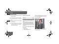
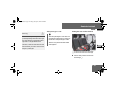
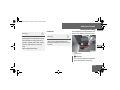
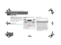
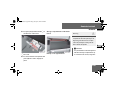
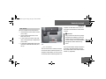
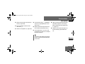
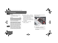
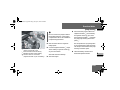
A statement by the child restraint manufacturer of compliance with this standard can be found on the instruction
label on the restraint and in the instruction manual provided with the restraint.
When using any infant or child restraint
system, make sure to carefully read and
follow all manufacturer’s instructions for
installation and use.
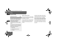
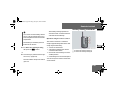
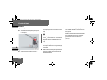
Please read and observe warning labels
affixed to inside of vehicle and to infant
or child restraints.
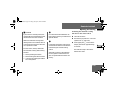
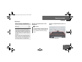
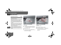
Passenger sun visor with warning sticker
nf_BA.book Page 61 Friday, January 25, 2008 3:53 PM
Safety
Occupant safety
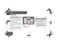
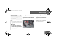
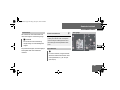
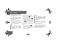
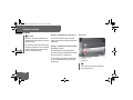
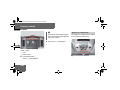
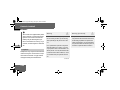
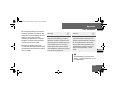
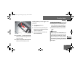
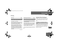
ISOFIX child seat securing system/
Child seat anchors - LATCH type
ISOFIX is a standardized securing system on the rear seats for special LATCH
(Lower Anchors and Tethers for Children) child restraint systems with
matching mounting fittings.
N00.00-2620-31
Warning symbol for rearward-facing child
seat
i
Non-LATCH type child seats may also
be used and can installed using the
vehicle’s seat belt system. Install
child seat according to manufacturer’s instructions.
The LATCH type anchors for child restraint systems are installed between
the seat cushion and the backrest:
on the outside left and right on narrow rear bench seats with 3 seats
on the outside left on rear bench
seats with 2 seats
61
2
nf_BA.book Page 62 Friday, January 25, 2008 3:53 PM
Safety
Occupant safety
Warning
2
G
A LATCH type child restraint system that
has been secured using the ISOFIX child
seat securing system is unable to provide
adequate protection for children who
weigh more than 48 lbs (22 kg). For this
reason, only secure children weighing
less than 48 lbs (22 kg) in a LATCH type
child restraint system secured using the
ISOFIX child seat securing system. If the
child weighs more than 48 lbs (22 kg),
you should secure the LATCH type child
restraint system with a lap-shoulder belt.
62
Warning
G
If the child restraint system has not been
installed correctly on a suitable vehicle
seat, the child cannot be restrained in the
event of an accident or sudden braking
and could be seriously or fatally injured.
You must therefore observe the installation instructions issued by the child restraint system manufacturer when
installing a child restraint system.
Continued
Warning (Continued)
G
On the rear bench seat, only use LATCH
type child restraint systems with ISOFIX
child seat mountings that have been recommended by the manufacturer.
An incorrectly installed child restraint system could come loose and the child or
other vehicle occupants could be fatally
injured. You must therefore make sure
that the child restraint system is engaged
in the securing rings on the left and righthand sides after it has been installed.
nf_BA.book Page 63 Friday, January 25, 2008 3:53 PM
Safety
Occupant safety
Warning
G
If the child restraint system or its securing
system, for example the ISOFIX child seat
securing system, are damaged or have
been subjected to a load in an accident,
the child secured in it could suffer severe
or fatal injuries in the event of an accident, heavy braking or a sudden change
of direction.
Continued
Warning (Continued)
G
For this reason, have restraint systems
and their mountings checked immediately
and replaced if necessary at a qualified
specialist workshop which has the necessary specialist knowledge and tools to
carry out the work required if they are
damaged or have been subjected to a
load in an accident.
The manufacturer recommends that you
use an authorized Sprinter Dealer for this
purpose. In particular, work relevant to
safety or on safety-related systems must
be carried out at a qualified specialist
workshop.
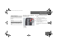
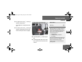
!CAUTION
Take care not to trap the seat belt on
the middle seat when you install the
child restraint system.
2
1 Securing rings - LATCH type anchors
63
nf_BA.book Page 64 Friday, January 25, 2008 3:53 PM
Safety
Occupant safety
Warning
2
G
Do not leave children unsupervised in the
vehicle, even if they are secured by a child
restraint system. The children could:
injure themselves on parts of the vehicle
be seriously or even fatally injured by
prolonged exposure to extreme heat
or cold
Warning
G
Do not expose child restraint systems to
direct sunlight. Metallic parts of the child
restraint system could heat up, for example, and the child could burn him/herself
on the hot parts.
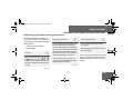
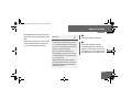
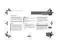
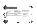
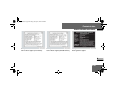
The TopTether anchorages are on the
feet of the rear bench seat.
If the children open a door, they could:
cause injury to others as a result
get out of the vehicle and could either injure themselves when doing so or they
could be injured by passing vehicles
sustain serious injuries if they were to
fall out of the vehicle, due in particular
to the height of the passenger compartment from the ground
64
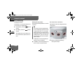
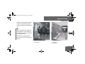
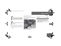
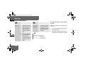
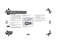
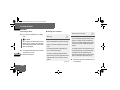
TopTether
1 Head restraints
2 TopTether anchorages
nf_BA.book Page 65 Friday, January 25, 2008 3:53 PM
Safety
Occupant safety
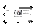
Slide head restraint 1 upward.
Guide TopTether belt 4 under head
restraint 1 from the front and between the two head restraint bars.
Hook TopTether hook 3 into
TopTether anchorage 2 on the feet
of the bench seat.
If necessary, slide head restraint 1
back down a little ( page 121).
Make sure that TopTether belt 4
can move freely.
Install the LATCH type child restraint
system with TopTether. The manufacturer’s installation instructions
must be observed.
2 TopTether anchorage
3 TopTether hook
4 TopTether belt of LATCH type child restraint system
65
2
nf_BA.book Page 66 Friday, January 25, 2008 3:53 PM
Safety
Emergency exit
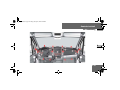
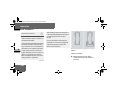
Emergency exit
Emergency exit window*
2
Warning
The vehicle can be equipped with an
emergency exit window. The emergency
exit window is only intended for emergencies and may only be opened when
the vehicle is stationary.
In an emergency or following an accident, the occupants of the vehicle can
exit the vehicle via the open emergency
exit window.
The emergency exit window is the first
window behind the driver’s seat on the
driver’s side. It bears the letters “Emergency Exit”.
66
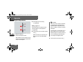
G
Compliance with the following requirements is essential in order to be able to
safely use the emergency exit window in
the event of an emergency:
1 Handles
2 Safety bolts
3 Locking mechanisms
Inform the vehicle occupants about
the emergency exit window and explain its operation before setting out.
Clearly point out the known risks
here.
Continued
nf_BA.book Page 67 Friday, January 25, 2008 3:53 PM
Safety
Emergency exit
Warning (Continued)
G
Only vehicle occupants who are able
to operate the emergency exit window are permitted to sit next to the
emergency exit window.
Access to the emergency exit window
must be free of obstacles. Do not
place any large or heavy objects on
the seats or in front of the seats next
to the emergency exit window.
Do not use the window handles as
hooks, e.g., for lightweight objects,
bags or items of clothing.
Warning
G
Please observe the following instructions
to reduce the risk of an accident or injury
when exiting the vehicle through the
emergency exit window:
Only open the emergency exit window
when the vehicle is stationary.
Take care not to trap anyone when
closing and opening the emergency
exit window. Somebody must hold the
emergency exit window open.
Warning (Continued)
G
Pay attention to the traffic conditions
when opening the emergency exit
window and make sure there is sufficient clearance.
Pay attention to the traffic conditions
when exiting the vehicle and take account of the vehicle height and the
surrounding conditions.
Extreme caution must be exercised in particular if there are children in the vicinity.
Continued
67
2
nf_BA.book Page 68 Friday, January 25, 2008 3:53 PM
Safety
Emergency exit
Warning
2
G
If you continue your journey without closing and locking the emergency exit window, it may come out of its frame and
cause an accident.
You should, therefore, check the locking
mechanism and safety bolts on the emergency exit window before setting out.
The emergency exit window may only be
opened when the vehicle is stationary.
68
!CAUTION
To close: close the window.
Make sure there is enough space to
open the emergency exit window.
You must hold the open window in
position. Otherwise, you could damage it.
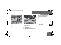
Turn both handles 1 to a horizontal
position. Make sure that the locking
mechanisms 3 are located on the
inside of the window frame.
To open: turn both handles 1 to a
vertical position. This releases the
safety bolts 2.
Renew the safety bolts 2 before driving the vehicle again.
The window is unlocked.
Use the handles to push the window
outward and hold it steady. Make
sure you have enough space to do
this.
The window is locked.
Please contact your authorized
Sprinter Dealer for information about
how to do this.
nf_BA.book Page 69 Friday, January 25, 2008 3:53 PM
Safety
Driving safety systems
Driving safety systems
In this section, you will find information
about the following driving safety systems:
ABS (Antilock Brake System)
BAS (Brake Assist)
ESP® (Electronic Stability Program)
ASR (acceleration skid control)
EBV (electronic brake force distribution)
i
The maximum effect of ABS, BAS,
ESP®, ASR and EBV can only be
achieved if you:
always drive with the correct tire
pressures adjusted according to
the load ( page 361)
use winter tires (M+S tires) in
wintry conditions, with snow
chains if necessary
Warning
G
There is an increased risk of an accident if
you:
drive too fast, in particular when cornering and on a wet or slippery road surface
drive too close to the vehicle in front
The driving safety systems described in
this section cannot reduce this risk and
are unable to override the laws of physics.
Always adapt your driving style to the prevailing road and weather conditions, and
maintain an adequately safe distance
from other road users as well as any obstacles on the road.
69
2
nf_BA.book Page 70 Friday, January 25, 2008 3:53 PM
Safety
Driving safety systems
i
Only use wheels with the recommended tire sizes ( page 623), otherwise the driving safety systems will
not work correctly.
2
Antilock Brake System (ABS)
ABS regulates the brake pressure in
such a way that the wheels do not lock
when you brake. This allows you to continue steering when braking.
ABS works from a speed of about 3 mph
(5 km/h) upwards, regardless of road
surface conditions.
ABS works on slippery surfaces, even
when you only brake gently.
Warning
G
Do not depress the brake pedal several
times in quick succession (pumping). Depress the brake firmly and evenly. Pumping the brake pedal may reduce the
braking effect.
There is a malfunction if the - indicator lamp is permanently lit while the engine is running ( page 466).
Despite this, the normal driving and
braking functions remain available.
70
nf_BA.book Page 71 Friday, January 25, 2008 3:53 PM
Safety
Driving safety systems
Braking
If ABS intervenes during braking, you will
feel the steering wheel vibrate gently
and the brake pedal pulsate.
If ABS intervenes:
Continue to depress the brake pedal
firmly until the braking situation is
over.
For full brake application:
Depress the brake pedal with maximum force.
Warning
G
Always adapt your driving style to the prevailing road and weather conditions, and
maintain an adequately safe distance
from other road users as well as any obstacles on the road.
If ABS malfunctions, the wheels could
lock when you brake. This means that the
steerability of the vehicle is restricted
during braking and the stopping distance
may increase. If ABS is deactivated due to
a malfunction, BAS is also deactivated.
Brake Assist (BAS)
Brake Assist operates in emergency
braking situations. If you depress the
brake pedal quickly, BAS automatically
increases the brake pressure, thereby
reducing the stopping distance.
Keep the brake pedal firmly depressed until the emergency braking
situation is over.
ABS prevents the wheels from locking.
When you release the brake pedal, the
brakes will work as normal again. BAS is
deactivated.
71
2
nf_BA.book Page 72 Friday, January 25, 2008 3:53 PM
Safety
Driving safety systems
Vehicles without steering wheel buttons:
There is a malfunction if the k indicator lamp is permanently lit while the
engine is running ( page 73).
2
Warning
G
If BAS malfunctions, the brake system is
still available with the full brake boosting
effect. In an emergency braking situation,
however, the braking force will not be additionally boosted automatically and the
stopping distance may increase.
72
Electronic Stability Program
(ESP®)
ESP® monitors driving stability and detects a tendency of the vehicle to understeer or oversteer (skidding) in good
time. ESP® stabilizes the vehicle by
braking individual wheels, limiting the
engine power output, and greatly assists
you when driving on wet or slippery road
surfaces. ESP® also stabilizes the vehicle when braking.
When ESP® intervenes, the v warning lamp in the speedometer flashes.
Warning
G
Proceed as follows if the v warning
lamp in the speedometer flashes:
Do not deactivate ASR under any circumstances.
Only depress the accelerator pedal as
far as necessary when pulling away.
Adapt your driving style to suit the
prevailing road and weather conditions.
Otherwise, the vehicle could begin to
skid.
ESP® cannot reduce the risk of an accident if you drive too fast. ESP® is unable
to override the laws of physics.
nf_BA.book Page 73 Friday, January 25, 2008 3:53 PM
Safety
Driving safety systems
There is a malfunction if the # indicator lamp is permanently lit while the engine is running ( page 468).
If ESP® malfunctions, engine power output may be reduced.
!CAUTION
Only operate the vehicle briefly (maximum of 10 seconds) on a brake dynamometer. The key must be turned
to position 1 in the ignition lock during this time. You could damage the
drive train or the brake system.
!CAUTION
Do not operate the vehicle on a roller
dynamometer (for example for performance testing). If you wish to operate the vehicle on a roller
dynamometer, please consult an authorized Sprinter Dealer beforehand.
You could otherwise damage the
drive train or the brake system.
Acceleration skid control (ASR)
ASR improves traction for a sustained
period, i.e. the transfer of power from
the tires to the road surface, and thus
also improves the driving stability of the
vehicle. ASR assists you when pulling
away and accelerating, especially on
smooth and slippery surfaces.
ASR brakes individual drive wheels and
limits the engine torque to prevent the
drive wheels from spinning. When ASR
intervenes, the v indicator lamp in
the speedometer flashes.
73
2
nf_BA.book Page 74 Friday, January 25, 2008 3:53 PM
Safety
Driving safety systems
If the road surface is not capable of providing sufficient traction, bearing in
mind the tires, load and gradient, it is
not be possible to pull away smoothly
even with ASR.
2 Vehicles without steering wheel but-
tons:
There is a malfunction if the k indicator lamp is permanently lit while the
engine is running ( page 73).
If ASR malfunctions, engine power output may be reduced.
74
Activating/deactivating ASR
ASR is automatically activated as soon
as the engine is switched on.
It may be best to deactivate ASR in the
following situations:
if snow chains are being used
in deep snow
on sand or gravel
If you deactivate ASR:
the engine’s torque is then no longer
limited and the drive wheels could
spin; the spinning wheels produce a
cutting effect for better traction
traction control still intervenes by
braking if one drive wheel reaches its
grip limit, for example if the surface
under one side of the vehicle is slippery. The wheel is then braked to increase traction in this situation.
ESP® still intervenes to stabilize the
vehicle
nf_BA.book Page 75 Friday, January 25, 2008 3:53 PM
Safety
Driving safety systems
Warning
G
The ASR switch is located on the center
console.
The v warning lamp in the speedometer lights up.
ESP® remains active despite ASR having
been deactivated and carries out braking
interventions if this is necessary to improve driving stability. The v warning
lamp flashes.
If ASR is deactivated, there is an increased risk that the brake system of your
vehicle could overheat and be damaged
when subjected to high loads for a long
period of time. A hot brake system also increases the stopping distance.
To switch off: press upper
section 1 of the switch.
To switch on: press upper
section 1 of the switch again.
N54.25-2916-31
2
The v warning lamp in the speedometer goes out.
1 To deactivate/activate ASR
For this reason, only deactivate ASR when
it is absolutely necessary.
75
nf_BA.book Page 76 Friday, January 25, 2008 3:53 PM
Safety
Driving safety systems
Electronic brake force distribution
(EBV)
EBV monitors and regulates the brake
pressure at the rear wheels to improve
driving stability during braking.
2
Warning
G
If EBV malfunctions, the brake system is
still available with the full brake boosting
effect. However, the rear wheels may
lock, for example if the brakes are applied
with maximum force. You could then lose
control of the vehicle and cause an accident. Always adapt your driving style to
the change in handling characteristics.
Have the system checked at an authorized Sprinter Dealer as soon as possible.
76
There is a malfunction if the #, k,
- and 6 indicator lamps are permanently lit while the engine is running
( page 462).
nf_BA.book Page 77 Friday, January 25, 2008 3:53 PM
Safety
Anti-theft systems
Anti-theft systems
Immobilizer
The immobilizer prevents the vehicle
from being started without the correct
key.
To switch on: remove the key from
the ignition lock ( page 111).
To switch off: switch on the ignition
( page 111).
Anti-theft alarm system (ATA)*
A visual and audible alarm is triggered if
the alarm system is enabled and:
a door is opened
the hood is opened
Deactivating the anti-theft alarm
system
Unlock the vehicle using the Œ
button on the key ( page 83).
Enabling the alarm system
The indicator lamp in the central
locking switch ( page 104) goes
out.
Close all the doors.
i
Lock the vehicle using the ‹ button on the key ( page 83).
The indicator lamp in the central
locking switch ( page 104) flashes.
The vehicle locks again automatically if you do not open a door within 40
seconds after unlocking the vehicle.
77
2
nf_BA.book Page 78 Friday, January 25, 2008 3:53 PM
Safety
Anti-theft systems
i
The alarm system will be triggered if
the vehicle has been locked with the
key and is then unlocked from the inside.
2
Switching off the alarm
Insert the key into the ignition lock.
or
Press the Πbutton ( page 83).
The alarm is switched off.
Tow-away protection*
A visual and audible alarm is triggered if
the inclination of the vehicle changes
while tow-away protection is enabled.
i
The tow-away protection alarm is
triggered shortly before the wheel
leaves the ground if the vehicle is being jakked up on one side, for example.
Enabling tow-away protection
Tow-away protection is automatically
enabled approximately 20 seconds after
you lock the vehicle.
78
Tow-away protection is automatically
deactivated when you unlock the vehicle.
Deactivating the tow-away protection for transportation
Deactivate tow-away protection if the
vehicle is transported or loaded onto another vehicle. This will prevent false
alarms.
The button is located in the overhead
control panel.
nf_BA.book Page 79 Friday, January 25, 2008 3:53 PM
Safety
Anti-theft systems
Turn the key to position 0 or 1
( page 111) in the ignition lock or
remove the key.
i
When the ignition is switched off
( page 111), you cannot deactivate
tow-away protection.
1 To deactivate tow-away protection
2 Indicator lamp
Press button 1.
Indicator lamp 2 lights up for approximately 5 seconds after the button is released.
Lock the vehicle using the key.
Tow-away protection remains deactivated until you lock the vehicle again.
Interior motion sensor*
If the anti-theft alarm system is enabled
and the vehicle is locked, a visual and
audible alarm is triggered if one of the
side windows or the rear window on your
vehicle is smashed and someone reaches into the interior, for example.
Enabling the interior motion sensor
Close:
the side windows
the sliding sunroof
This will prevent false alarms.
Lock your vehicle.
79
2
nf_BA.book Page 80 Friday, January 25, 2008 3:53 PM
Safety
Anti-theft systems
Turn the key to position 0 or 1
( page 111) in the ignition lock or
remove the key.
The interior motion sensor is enabled
after approximately 40 seconds.
i
2
Press button 1.
Do not leave anything (for example
mascots or coat hangers) hanging on
the rear-view mirror or on the grab
handles on the roof trim. This will prevent false alarms.
Deactivating the interior motion
sensor
Deactivate the interior motion sensor if
people or animals remain in the locked
vehicle. This will prevent false alarms.
The button is located in the overhead
control panel.
80
Indicator lamp 2 lights up for approximately 5 seconds after the button is released.
1 To deactivate the interior motion sensor
2 Indicator lamp
i
The interior motion sensor remains
deactivated until you lock the vehicle
again.
nf_BA.book Page 81 Friday, January 25, 2008 3:53 PM
Controls in detail
Controls in detail
Opening and closing............. 83
Key positions........... 111
Seats........... 112
Steering wheel adjustment........... 127
Lighting........... 129
Instrument cluster........... 142
Operating system without steering wheel buttons........... 147
Operating system with steering wheel buttons*........... 151
Driving and parking........... 183
Automatic transmission........... 201
Good visibility........... 208
81
3
nf_BA.book Page 82 Friday, January 25, 2008 3:53 PM
Controls in detail
Air conditioning........... 215
Auxiliary heating/ventilation*........... 236
Open air........... 244
Driving systems........... 248
Operating the vehicle........... 273
3
Transporting........... 276
Features........... 287
82
nf_BA.book Page 83 Friday, January 25, 2008 3:53 PM
Controls in detail
Opening and closing
Opening and closing
Your vehicle is supplied with either 2 or
4* remote keyless entry transmitters or
4 keys* without remote control.
Vehicle keys* which were not included
with delivery must be activated before
they can be used. You can obtain further
information at any authorized Sprinter
Dealer.
When leaving the vehicle, always take
the key* or remote keyless entry transmitter with you and lock the vehicle. The
engine could be started by anyone with
a valid key* or remote keyless entry
transmitter that is left inside the vehicle.
You will find information about opening
and closing your vehicle with the key in
the “Locking and unlocking the vehicle
with the key” section ( page 88).
Remote control with key
Included with your vehicle are 2 or 4* remote keyless entry transmitters with a
folding mechanical key.
i
USA only:
This device complies with Part 15 of
the FCC rules. Operation is subject
to the following two conditions:
(1) This device may not cause harmful interference, and
(2) this device must accept any interference received, including interference that may cause undesired
operation.
Any unauthorized modification to
this device could void the user’s authority to operate the equipment.
83
3
nf_BA.book Page 84 Friday, January 25, 2008 3:53 PM
Controls in detail
Opening and closing
i
Canada only:
This device complies with RSS-210
of Industry Canada.
3
Remote controls with keys which were
not included with delivery must be activated at an authorized Sprinter Dealer
before they can be used.
The remote keyless entry transmitter
transmits in all directions. It does not
have to be pointed at the vehicle.
The remote keyless entry transmitter
has an average range of about 32 ft
(about 10 m). Always verify the correct
operation of the remote keyless entry
84
transmitter by checking whether the
locking knobs on the driver's and passenger's doors move down and whether
the turn signals flash.
The remote control unlocks the driver's
door and/or all doors centrally. If programmed as a factory setting, it locks
the following centrally:
the driver’s and passenger’s door
the sliding doors
the rear doors
i
If the driver’s or passenger’s door is
not completely closed, the respective
door is not locked.
If one sliding door or rear door is not
completely closed, all doors of the
load compartment are not locked.
The remote keyless entry transmitter
will not function when there is a vehicle
key inserted in the ignition lock.
nf_BA.book Page 85 Friday, January 25, 2008 3:53 PM
Controls in detail
Opening and closing
Warning
G
Warning (Continued)
G
Do not leave children unsupervised in the
vehicle, even if they are secured by a child
restraint system.
get out of the vehicle and could either injure themselves when doing so or they
could be injured by passing vehicles
The children could:
be severely or even fatally injured by prolonged exposure to intense heat
injure themselves on parts of the vehicle
unlock the door on vehicles with an electric sliding door by pressing the central
locking button, and then open the doors
and thereby injure other persons
Continued
Remote control with key
1
2
3
4
5
To unlock the sliding doors and
rear doors and opens or closes the electric sliding door*
ΠUnlocking button
‹ Locking button
Release button for mechanical key
Battery check lamp.
3
!
Do not expose the key to high levels
of electromagnetic radiation, otherwise this may interfere with the functions of the key.
Protect the key from moisture to prevent malfunctions.
85
nf_BA.book Page 86 Friday, January 25, 2008 3:53 PM
Controls in detail
Opening and closing
i
To prevent theft, only use the remote
control in the immediate vicinity of
the vehicle.
In an emergency, the driver’s door
and rear door can also be unlocked
manually using the key.
3
As a precaution, both remote controls
should always be carried.
Checking the batteries
Press the Œ or ‹ button for
longer than 2 seconds.
86
The battery check lamp 5 comes on
briefly to indicate that the remote
control batteries are in order.
Locking and unlocking the vehicle
with the remote control
Change the batteries immediately if
the lamp does not light up briefly
during check ( page 540).
Unlocking the driver's door
i
If the batteries are checked within
signal range of the vehicle, pressing
the Œ or ‹ button will lock or
unlock the vehicle accordingly.
Press the Πbutton.
The turn signals flash once.
The anti-theft alarm system (ATA)* is
deactivated.
i
If you unlock the vehicle using the
key and do not open a door within 40
seconds, the vehicle locks again automatically.
nf_BA.book Page 87 Friday, January 25, 2008 3:53 PM
Controls in detail
Opening and closing
Unlocking the vehicle centrally
Locking the vehicle centrally
Unlock the driver's door.
Press the ‹ button.
Press the Πbutton within 2 seconds again.
The turn signals flash once.
The turn signals flash three times if:
the drive authorization system or
the anti-theft alarm system
(ATA)* is activated
all the doors are closed
Unlocking the sliding doors and the
rear door*
When the vehicle is locked, the
button can only be used to unlock the
sliding doors and the rear door.
Press the
button.
The turn signals flash once.
i
Opening the electric sliding doors
Make sure that the locking knobs
have dropped down.
Press and hold the
3
button.
The turn signals flash once.
87
nf_BA.book Page 88 Friday, January 25, 2008 3:53 PM
Controls in detail
Opening and closing
Locking and unlocking the vehicle
with the key
Unlocking the vehicle
NCV2
If the doors can no longer be locked or
unlocked with the remote control, you
can lock and unlock the driver's door
and the rear doors with the key.
N72.10-2147-31
N72.10-2149-31
3
Rear door
Driver's door
1 To lock
2 To unlock
1 To lock
2 To unlock
Insert the key all the way into the
door lock and turn it in direction 2.
The door is unlocked.
88
nf_BA.book Page 89 Friday, January 25, 2008 3:53 PM
Controls in detail
Opening and closing
i
Locking the vehicle
The anti-theft alarm system (ATA) is
triggered when you open the vehicle
using the key.
Only the driver's door and the rear doors
can be locked with the key.
The alarm can be disabled in the following ways:
Press the Πbutton on the remote
control.
or
Insert the key into the ignition lock.
For all other doors, press the locking
knob down.
Close the doors.
The doors are locked.
Insert the key all the way into the
rear door lock and turn it to the left.
The rear doors are locked.
Insert the key all the way into the
driver’s door lock and turn it to the
right.
Opening the driver’s or passenger’s door from the inside
Warning
G
Make sure nobody can become trapped
when you close or open the doors. Take
particular care, especially when children
are near the vehicle.
Make sure there is sufficient clearance
and that the traffic area is clear when opening the doors.
You could otherwise injure yourself and
others.
The driver’s door is locked.
89
3
nf_BA.book Page 90 Friday, January 25, 2008 3:53 PM
Controls in detail
Opening and closing
You can open the driver’s/passenger’s
door from the inside at any time, even if
it is locked. Open door only when conditions are safe to do so.
i
Sliding door
Warning
G
If the vehicle is parked on an incline, the
sliding door may move of its own accord if
it is open but not engaged. You or others
could be trapped.
3
Make sure that the sliding door is engaged
in the active retainer.
1 Inside door handle
2 Locking knob
Pull door handle 1.
The door opens.
90
The sliding door is equipped with an
active retainer, which engages the
door at the end stop when opened.
Always make sure that the open sliding door is correctly engaged in the
detent.
To open the sliding door, it is necessary to pull the outside door handle
first, or press the button on the inside
handle, to release the sliding door
from its detent.
nf_BA.book Page 91 Friday, January 25, 2008 3:53 PM
Controls in detail
Opening and closing
Opening/closing the sliding door
from the outside
i
When you open/close the sliding
door, you can also detent it around
half way so that it is not always necessary to open the door to the end
stop to get in and out of the vehicle.
The intermediate detent does not fully engage the sliding door.
To open: pull door handle 1 to
open the sliding door.
Hold door handle 1 and slide the
sliding door towards the rear as far
as the stop.
1
2
3
4
Outside door handle
Button
Inside door handle
Locking knob
To close: pull door handle 1, to release the sliding door from its detent
and, holding door handle 1, pull the
door firmly towards the front until it
engages.
91
3
nf_BA.book Page 92 Friday, January 25, 2008 3:53 PM
Controls in detail
Opening and closing
Opening/closing the sliding door
from the inside
Open sliding door only when conditions
are safe to do so.
To unlock: pull locking knob 4 up.
3
Only this sliding door unlocks. The
other doors remain locked.
To open: press button 2 to open
the unlocked sliding door.
Hold door handle 3 and slide the
sliding door towards the rear as far
as the stop.
92
To close: press button 2 to release
the sliding door from its detent and,
holding door handle 3, pull the door
firmly towards the front until it engages.
To lock: press locking knob 4
down.
Only this sliding door is locked.
Electric closing aid*
Your vehicle may be equipped with an
electric closing aid.
The electric closing aid helps you to
close the sliding door. Closing the door
does not require as much effort.
Electric sliding door*
Depending on the vehicle’s equipment,
there are electric sliding doors on the
left and/or right-hand side.
Open sliding door only when conditions
are safe to do so. You can operate the
electric sliding door as follows:
Switch on the center console
Switch in the doorway (B-pillar)
Inside door handle
Outside door handle
Remote control
nf_BA.book Page 93 Friday, January 25, 2008 3:53 PM
Controls in detail
Opening and closing
i
Following a battery disconnection or
malfunction, it is necessary to fully
close the sliding door once by pressing and holding the switch on the
center console or in the doorway
( page 93) and then to fully open
and close the door once by pressing
one of the switches briefly. This restores normal operation of the sliding door.
If the electric drive of the sliding door is
at risk of overheating, e.g. as a result of
frequent opening and closing within a
short amount of time, the sliding door
opens completely and is locked (function override). After approx. 30 seconds,
the sliding door is again operational.
i
In the event of a malfunction or if the
battery is disconnected, you can disconnect the sliding door from the
electric drive via the unlocking mechanism and then open/close the sliding door manually ( page 96).
Opening/closing using the switch
Observe the notes on anti-trap protection ( page 98).
N72.16-2135-31
3
Sliding door switch on the center console
1 To close the sliding door/to program the
key ( page 97)
2 To open the sliding door
93
nf_BA.book Page 94 Friday, January 25, 2008 3:53 PM
Controls in detail
Opening and closing
i
On vehicles with a partition, the
switch is located on the partition
near the doorway level with the inside door handle.
N72.16-2119-31
3
Sliding door switch in the doorway (B-pillar)
The indicator lamp in the switch flashes. The sliding door opens.
To unlock the sliding door from inside: press lower part of the central
locking switch on the center console
( page 104).
To close the sliding door: briefly
press upper part 1 of the switch on
the center console or briefly press
switch 3 in the doorway.
The indicator lamp in the switch goes
out.
The indicator lamp in the switch
flashes. The sliding door closes and a
signal sounds.
3 To open/close the sliding door
or
Pull the locking knob of the sliding
door up ( page 91).
94
To open the sliding door: briefly
press lower part 2 of the switch on
the center console or briefly press
switch 3 in the doorway.
nf_BA.book Page 95 Friday, January 25, 2008 3:53 PM
Controls in detail
Opening and closing
To stop the sliding door: press lower/upper part of the switch on the
center console or press switch 3 in
the doorway.
The sliding door stops.
To lock the sliding door from inside: press lower part of the central
locking switch on the center console
( page 104).
The indicator lamp in the switch comes on.
or
Press the locking knob of the sliding
door down ( page 91).
Proceed as follows in the event of unfavorable operating conditions, e.g. frost,
ice or heavy soiling:
To open the sliding door: press
lower part 2 of the switch on the
center console or press and hold
switch 3 in the doorway.
The indicator lamp in the switch
flashes. The sliding door closes and a
signal sounds.
Release the switch.
The sliding door stops.
The indicator lamp in the switch
flashes. The sliding door unlocks and
opens, and a signal sounds.
To stop the sliding door: press lower/upper part of the switch on the
center console or press switch 3 in
the doorway.
The sliding door stops.
To close the sliding door: press upper part 1 of the switch on the center console or press and hold
switch 3 in the doorway.
To lock the sliding door from inside: press lower part of the central
locking switch on the center console
( page 104).
95
3
nf_BA.book Page 96 Friday, January 25, 2008 3:53 PM
Controls in detail
Opening and closing
The indicator lamp in the switch
comes on.
or
Press the locking knob of the sliding
door down ( page 91).
i
3
The indicator lamp in the switch on
the center console lights up whenever the sliding door is open.
The sliding door can jam under unfavorable operating conditions such as frost,
icing or heavy dirt. In this case, clean the
door entry and proceed as follows:
To open the sliding door: unlock
the sliding door ( page 94).
96
Press and hold lower part 2 of the
switch on the center console or press
and hold switch 3 in the doorway.
The indicator lamp in the switch
flashes. The sliding door opens.
Release the switch.
The sliding door stops.
Opening/closing using the inside
and outside door handles
Observe the notes on anti-trap protection ( page 98).
The sliding door stops.
To close the sliding door: press
and hold upper part 1 of the switch
on the center console or press and
hold switch 3 in the doorway.
N72.16-2118-31
The indicator lamp in the switch
flashes. The sliding door closes and a
signal sounds.
Release the switch.
1 Button
nf_BA.book Page 97 Friday, January 25, 2008 3:53 PM
Controls in detail
Opening and closing
Press button 1 again or pull outside
door handle 2 again.
The sliding door stops.
Opening/closing with the remote
control
Programming the remote control
If the vehicle is equipped with 2 sliding
doors, it is only possible to program the
remote control for one of the sliding
doors.
Press and hold the
button for
more than half a second.
2 Outside door handle
Briefly press button 1 or pull outside door handle 2.
The sliding door opens or closes.
When closing, a signal sounds.
The sliding door unlocks and opens
or closes.
Press the
3
N72.16-2136-31
button again.
The sliding door stops.
1 Switch for sliding door on left-hand side
2 Switch for sliding door on right-hand side
97
nf_BA.book Page 98 Friday, January 25, 2008 3:53 PM
Controls in detail
Opening and closing
Make sure that the doors are closed.
Anti-trap protection
Switch on the ignition ( page 111).
Press and hold the upper part of
relevant switch 1 or 2 on the center console for 5 seconds.
3
The indicator lamp in the switch for
the sliding door concerned flashes
and a warning tone sounds three
times as confirmation.
Warning
G
The anti-trap protection function does not
eliminate the possibility of fingers or other
parts of the body being trapped against
the door frame and therefore does not
eliminate the risk of injury.
Always make sure that nobody is within
the operating range of the sliding door.
If the sliding door is obstructed during
the opening procedure, it moves back in
the opposite direction slightly and stops.
98
If the sliding door is obstructed during
the closing procedure, it opens fully
again.
i
The anti-trap protection is programmed to be less sensitive when
you press and hold the switch on the
center console or the switch in the
doorway than when the door opens
of its own accord.
Resetting the electric sliding door
In the event of serious malfunctions or if
you disconnect the battery, you will
need to reset the sliding door.
nf_BA.book Page 99 Friday, January 25, 2008 3:53 PM
Controls in detail
Opening and closing
Resetting the sliding door: Close
the sliding door completely once by
pressing and holding down the
switch on the center console or in
the doorway.
Rear doors
You can fix the rear doors in place at an
angle of approximately 90° or 270°.
Then
Warning
Open and close the sliding door completely once by pressing and releasing one of the switches.
When you open the rear door:
This restores normal operation of the
sliding door.
G
there must be sufficient clearance
make sure that nobody can become
trapped
Warning
G
The rear lamps are concealed by more
than 50% when you open the rear doors
through 90° or more.
The vehicle is then not sufficiently safeguarded at the rear and may only be seen
by other road users when they are close
to the vehicle. This could lead to an accident.
Make sure, therefore, that the vehicle is
safeguarded at the rear in accordance
with national legal requirements, e.g. with
a warning triangle.
99
3
nf_BA.book Page 100 Friday, January 25, 2008 3:53 PM
Controls in detail
Opening and closing
Opening the right-hand rear door
from the outside
Always make sure that the open rear
door is correctly engaged in the detent.
Opening the left-hand rear door from
the outside
3
1 Handle
Pull handle 1.
Swing the rear door out to the side
until it engages.
100
1 Release lever
Make sure that the right-hand rear
door is open and engaged.
Pull release lever 1 in the direction
of the arrow.
Swing the rear door out to the side
until it engages.
nf_BA.book Page 101 Friday, January 25, 2008 3:53 PM
Controls in detail
Opening and closing
Opening the rear doors to an angle of
270°
Pull door retainer 1 in the direction
of the arrow and hold it firmly.
Open the rear door beyond 90° so
that the door retainer can no longer
engage.
Release the door retainer and open
the door to an angle of 270°.
3
Warning
1 Door retainer
Open the rear door to an angle of approximately 45°.
G
Make sure that the traffic area is clear
when opening the rear doors beyond 90°.
You could otherwise injure yourself and
others.
2 Magnetic door retainer
With the rear door opened to an angle of 270°, push it against magnetic
door retainer 2 on the side wall.
101
nf_BA.book Page 102 Friday, January 25, 2008 3:53 PM
Controls in detail
Opening and closing
When the magnet on the rear door is
in contact with magnetic door retainer 2, the rear door is held in this position.
i
3
If you prefer to keep door retainer 1
( page 101) out of the loading area
when loading the vehicle, you can
swivel it 180° against the spring
pressure and onto the door, where it
engages. The door retainer then remains in this position and no longer
returns to its original position.
Before closing the door, release door
retainer 1 from the detent and return it to its original position.
102
Closing the rear doors from outside
Closing the rear doors from the 90° or
270° position
G
Pull the door away from the magnetic door retainer 1 if necessary
( page 101).
Warning
Make sure that nobody can become
trapped as you close the rear door.
Close the left-hand rear door firmly
from the outside.
Close the right-hand rear door firmly
from the outside.
Push the rear door closed firmly from
the outside.
The door retainer 1 ( page 101) is
automatically released from its detent.
nf_BA.book Page 103 Friday, January 25, 2008 3:53 PM
Controls in detail
Opening and closing
To unlock: slide catch 2 to the left.
Opening/closing the rear door from
the inside
You will see a white marking. Only
the rear door is unlocked. The other
doors remain locked.
The opening lever is on the inside of the
right-hand rear door. If a white marking
is visible, this indicates that the rear
door is unlocked. Open rear doors only
when conditions are safe to do so.
To open: pull opening lever 1 and
open the unlocked rear door.
Rear door
1 Opening lever
2 Catch
Always make sure that the open rear
door is correctly engaged in the detent.
Warning
G
Make sure that nobody can become
trapped as you close the rear door.
103
3
nf_BA.book Page 104 Friday, January 25, 2008 3:53 PM
Controls in detail
Opening and closing
To close: make sure that the lefthand rear door is closed.
Pull the right-hand rear door firmly
closed by the door handle.
To lock: slide catch 2 to the right.
Only the rear door is locked.
3
The white marking is no longer visible.
Locking and unlocking centrally
from the inside
Using the central locking switch, you
can centrally lock or unlock from the inside either the entire vehicle or the sliding doors and rear doors only.
104
Warning
G
Do not leave children unsupervised in the
vehicle, even if they are secured by a child
restraint system. The children could:
injure themselves on parts of the
vehicle
be severely or even fatally injured by
prolonged exposure to intense heat
If the children open a door, they could:
cause injury to others as a result
Continued
Warning (Continued)
G
get out of the vehicle and could either
injure themselves when doing so or
they could be injured by passing
vehicles
sustain serious injuries if they were to
fall out of the vehicle, due in particular
to the height of the passenger compartment from the ground
The central locking switch is located on
the center console.
nf_BA.book Page 105 Friday, January 25, 2008 3:53 PM
Controls in detail
Opening and closing
N54.25-2917-31
1 To lock/unlock the entire vehicle
2 To lock/unlock the sliding doors and
rear door
i
Locking the entire vehicle
If the key is in position 0 or no longer
in the ignition lock, the indicator
lamp in the central locking switch
lights up for 5 seconds after it is
pressed. It lights up permanently if
the key is in position 1 or 2 in the ignition lock.
Press upper part 1 of the switch
when the doors are closed.
The indicator lamp in the central locking
switch indicates when the sliding doors
and the rear door are locked. You can
determine whether the driver's door or
passenger's door is locked or unlocked
by the position of the locking knobs.
The indicator lamp in the switch
comes on.
Unlocking the entire vehicle
Press upper part 1 of the switch.
The indicator lamp in the switch goes
out.
105
3
nf_BA.book Page 106 Friday, January 25, 2008 3:53 PM
Controls in detail
Opening and closing
Locking the sliding doors and the
rear door
Press lower part 2 of the switch
when the doors are closed.
The indicator lamp in the switch
comes on.
3 Unlocking the sliding doors and the
rear door
Press lower part 2 of the switch.
The indicator lamp in the switch goes
out.
106
Automatic locking
As a standard feature on all vehicles, all
doors lock automatically when a speed
of 9 mph (15 km/h) is reached.
N54.25-2917-31
On some vehicles, depending on the
equipment, all doors lock automatically
as soon as the ignition is switched on*.
You can unlock and open a locked door
from the inside at any time.
1 To lock/unlock the entire vehicle
2 To lock/unlock the sliding doors and
rear door
nf_BA.book Page 107 Friday, January 25, 2008 3:53 PM
Controls in detail
Opening and closing
!CAUTION
i
If your vehicle is centrally locked, this
could hinder rescue operations from the
outside in the event of an accident.
For information about different settings, please contact your authorized
Sprinter Dealer.
When the automatic locking when
driving function is activated, there is
a risk of being locked out if the vehicle is pushed or towed.
For this reason, always deactivate
the automatic locking when driving
function:
before pushing the vehicle
before having the vehicle towed
if you are only leaving the vehicle
for a brief period
i
If activated, automatic locking is deactivated if the vehicle is unlocked or
locked using the central locking
switch.
Automatic locking is reactivated after the ignition is switched off or a
door is opened with the vehicle stationary.
Activating the automatic locking
function for the entire vehicle
Close all the doors.
Turn the key to position 1 or 2 in the
ignition lock ( page 111).
Press upper part 1 of the switch.
Keep it pressed for approximately
5 seconds.
The indicator lamp in the switch
flashes four times.
107
3
nf_BA.book Page 108 Friday, January 25, 2008 3:53 PM
Controls in detail
Opening and closing
Deactivating the automatic locking
function for the entire vehicle
Close all the doors.
Turn the key to position 1 or 2 in the
ignition lock ( page 111).
3
Press upper part 1 of the switch.
Keep it pressed for approximately
5 seconds.
The indicator lamp in the switch
flashes twice.
108
Activating the automatic locking
function for the sliding doors and the
rear door
Deactivating the automatic locking
when driving function for the sliding
doors and the rear door
Close all the doors.
Close all the doors.
Turn the key to position 1 or 2 in the
ignition lock ( page 111).
Turn the key to position 1 or 2 in the
ignition lock ( page 111).
Press lower part 2 of the switch.
Keep it pressed for approximately
5 seconds.
Press lower part 2 of the switch.
Keep it pressed for approximately
5 seconds.
The indicator lamp in the switch
flashes four times.
The indicator lamp in the switch
flashes twice.
nf_BA.book Page 109 Friday, January 25, 2008 3:53 PM
Controls in detail
Opening and closing
Partition sliding door*
The partition sliding door is in the partition between the cab and the load compartment.
Warning
Operating the partition sliding door
from inside the cab
To open: turn the key counterclockwise 3.
The sliding door is unlocked.
Slide the sliding door to the right as
far as the stop 2.
G
To close: slide the sliding door to the
left until it engages 1.
Make sure that nobody can become
trapped as you close the partition sliding
door.
The sliding door can be locked using
the key.
1 To close
2 To open
3 To unlock
109
3
nf_BA.book Page 110 Friday, January 25, 2008 3:53 PM
Controls in detail
Opening and closing
Operating the partition sliding door
from inside the load compartment
To open: press the lever to the
right 3.
The sliding door is unlocked.
Slide the sliding door to the left as far
as the stop 1.
To close: slide the sliding door to the
right until it engages 2.
3
1 To close
2 To open
3 To unlock
110
nf_BA.book Page 111 Friday, January 25, 2008 3:53 PM
Controls in detail
Key positions
Key positions
0 To remove the key, to lock the steering wheel
1 To unlock the steering wheel (power
supply for some consumers, e.g. radio)
2 To switch on the ignition (power supply for all consumers)
Preglow1 and drive position
3 To start
i
The key can only be removed from
position 0. Also observe the notes in
the “Driving and parking” section
( page 183).
To unlock the steering, turn the
steering wheel slightly while turning
the key to position 1.
On vehicles with a battery isolating
switch, you must first switch on the
electrical system ( page 340).
1 Only vehicles with a diesel engine
111
3
nf_BA.book Page 112 Friday, January 25, 2008 3:53 PM
Controls in detail
Seats
Seats
Driver’s and passenger’s seats
Warning
3
G
Only adjust the seats when the vehicle is
stationary and the handbrake is applied.
You could otherwise lose control of the
vehicle as a result of the seat moving and
cause an accident.
Warning
G
G
Observe the following points:
Avoid seat positions that do not allow
the seat belt to be routed correctly.
The shoulder section of the seat belt
must be routed across the middle of
your shoulder and must fit closely
across your chest. The lap section of
the belt must be routed as low as possible across your pelvic area, i.e.
across your hip joints. Never drive
with the backrest tilted too far back.
Position the backrest as vertically as
possible and sit upright.
Your arms should be slightly bent when
you are holding the steering wheel.
Make sure that nobody can become
trapped as the seat is adjusted. Never
place your hands under the seat or near to
moving parts.
Your seat must be adjusted in such a way
that you can wear the seat belt correctly
( page 39).
Continued
112
Warning (Continued)
Continued
nf_BA.book Page 113 Friday, January 25, 2008 3:53 PM
Controls in detail
Seats
Warning (Continued)
G
The distance from the pedals should
be such that you can depress them
fully.
Adjust the head restraint in such a
way that the upper edge of the head
restraint is level with your head.
Warning
G
Avoid seat positions in which you cannot
wear your seat belt correctly. They are a
safety hazard and must therefore be
avoided.
3
Make sure that you hear the seat engage. Otherwise, the seat is not correctly locked in place.
Injuries may be caused if these notes are
not observed.
113
nf_BA.book Page 114 Friday, January 25, 2008 3:53 PM
Controls in detail
Seats
Standard, comfort* and suspension*
seats
1
2
3
4
5
6
7
Seat fore-and-aft adjustment
Lumbar support adjustment
Backrest adjustment
Seat height adjustment
Seat angle adjustment
Seat suspension adjustment
Suspension lock lever
i
3
Different settings are possible, depending on the seat version.
Seat fore-and-aft adjustment
Pull lever 1 up.
Slide the seat forwards or backwards
until you can reach the pedals and
depress them.
Release lever 1.
Slide the seat forwards or backwards
slightly until it engages audibly.
Backrest adjustment
Turn thumbwheel 3 forward.
The backrest moves to an upright position.
Turn thumbwheel 3 backward.
The backrest tilts towards the rear.
114
nf_BA.book Page 115 Friday, January 25, 2008 3:53 PM
Controls in detail
Seats
Seat height adjustment
Push or pull lever 4 repeatedly until
you have reached the desired seat
height.
Seat angle adjustment*
Turn thumbwheel 5 forward.
The front of the seat cushion tilts
down.
Lumbar support adjustment*
i
Using the lumbar support, you can
increase the level of support that the
backrest provides to your spinal column.
Turn thumbwheel 2 upward.
This increases the support provided
to your lumbar region.
Turn thumbwheel 2 downward.
This reduces the support provided to
your lumbar region.
When the lumbar support is correctly
adjusted, it reduces strain on your
back while you are driving.
3
Turn thumbwheel 5 backward.
The front of the seat cushion tilts up.
115
nf_BA.book Page 116 Friday, January 25, 2008 3:53 PM
Controls in detail
Seats
Seat suspension adjustment*
Suspension lock*
The seat suspension must be adjusted
to your body weight. Only adjust the seat
suspension when the seat is unoccupied.
If the seat bounces up and down frequently, you can engage the seat the lower position of its suspension travel.
Relieve the load on the seat.
3 Select your body weight 88 to
265 lbs (40 to 120 kg) using thumbwheel 6 for optimal seat suspension.
The seat suspension becomes harder as you adjust it to a higher body
weight. The seat will then travel
down as far.
116
Turn lever 7 downward.
The next time the seat bounces, it
will engage.
i
The suspension lock will engage only
if your weight is identical or above
the adjusted suspension weight.
Turn lever 7 upward to release the
seat from the suspension lock.
The seat can now move up and down
again.
Swivelling front seats*
Warning
G
Only adjust the seats when the vehicle is
stationary and the handbrake is applied.
You could otherwise lose control of the
vehicle as a result of the seat moving and
cause an accident.
nf_BA.book Page 117 Friday, January 25, 2008 3:53 PM
Controls in detail
Seats
Warning
G
The driver’s and passenger’s seat must be
adjusted and properly engaged in the direction of travel for driving. Otherwise you
will not be able to operate the vehicle
safely.
The restraint systems in your vehicle will
only function as intended when the driver’s and passenger’s seat are engaged in
the direction of travel.
The driver’s and passenger’s seat can be
rotated by 180° to be opposite of the direction of travel.
The seats engage in the direction of travel or opposite the direction of travel as
well as at 50° pointing towards the exit.
!CAUTION
When rotating the seats, make sure
there is sufficient space. If necessary, move the seat fore or aft to
avoid colliding with adjacent add-on
parts.
Fold the handbrake lever down
as far as it will go. You could
otherwise damage the handbrake or the handbrake lever.
Fold the handbrake lever down as far as
it will go. You could otherwise damage
the handbrake or the handbrake lever.
i
Move the passenger’s seat forward
as far as it will go before rotating it
( page 114).
Make sure the handbrake is applied
and the handbrake lever is folded
down as far as it will go
( page 191).
Set the steering wheel so that there
is sufficient clearance for turning and
adjusting the driver’s seat
( page 127).
117
3
nf_BA.book Page 118 Friday, January 25, 2008 3:53 PM
Controls in detail
Seats
Warning
3
G
The seat release lever is located behind
the seat between the seat backrest and
the seat base.
Make sure nobody can become trapped
when unlocking and turning the seats.
Never hold your hands under the seat or
near moveable parts when turning the
seats.
The turning device is unlocked.
Release lever 1 again.
Turn the seat inwards to the desired
position.
Passenger’s seat
1 Lever
118
Press lever 1 on the back of the
seat to the middle and turn the seat
slightly inwards.
nf_BA.book Page 119 Friday, January 25, 2008 3:53 PM
Controls in detail
Seats
Warning
G
You could knock yourself against the unprotected pivoting frame if the seat is opposite of the direction of travel and pushed
right back in a longitudinal direction.
Therefore, center the seat above the seat
base whenever you leave it. Point out this
danger to passengers.
Twin passenger's seat*
Folding the seat cushion forward
i
The twin passenger’s seat does not
provide the same level of comfort as
the driver’s and passenger’s seats.
There is only restricted seat width
and legroom.
3
1 To release from the front anchorage
2 To release from the rear anchorage
Lift the seat cushion out of front
anchorage 1.
119
nf_BA.book Page 120 Friday, January 25, 2008 3:53 PM
Controls in detail
Seats
Pull the seat cushion towards the
front slightly and out of rear
anchorage 2.
Fold the seat cushion up by the rear
edge.
3
Positioning the seat cushion
Armrests*
Fold the seat cushion back.
Slide the seat cushion under the
backrest and into rear
anchorage 2.
i
Fold the seat cushion down.
You can store various articles in the
space under the twin passenger’s
seat.
Press the front of the seat cushion
down until it engages in front
anchorage 1.
1 To fold up the armrest
2 To unlock the armrest
3 To move the armrest to the desired position
120
nf_BA.book Page 121 Friday, January 25, 2008 3:53 PM
Controls in detail
Seats
Adjusting the armrest angle
Fold the armrest up by an angle of
more than 45° to unlock it 2.
Fold the armrest forward to the
stop 3. There are six closely spaced
positions in which the armrest can
engage if you raise it.
Folding up the armrest
If you do not wish to use the armrest,
fold it up by an angle of more than
90° 1.
Adjusting the head restraint
Head restraints
Warning
G
Only drive with the head restraints installed. You could otherwise suffer serious or fatal injuries in the area of the
upper spinal column.
Adjust the head restraint in such a way
that the upper edge of the head restraint
is level with your head.
Adjust your head restraint so that when
your head is relaxed the back of your
head is as close as possible to the head
restraint. This will support your head effectively in an accident. The head restraint must be engaged in a detent.
3
1 Release button
2 Height adjustment
3 Angle adjustment (comfort head restraint)
121
nf_BA.book Page 122 Friday, January 25, 2008 3:53 PM
Controls in detail
Seats
To raise: pull the head restraint up
to the desired position.
To lower: press release button 1
and slide the head restraint down to
the desired position.
3
To adjust the angle: hold the head
restraint by the lower edge and fold
it to the desired position.
Installing the head restraints
!CAUTION
Make sure that the head restraint is
reinstalled in such a way that its front
faces in the direction of travel (comfort head restraint).
Removing the head restraints
Insert the head restraint so that the
rod with the notches is in the direction of travel on the left.
Pull the head restraint up as far as it
will go.
Push the head restraint down until it
engages.
Press release button 1 and pull the
head restraint out.
122
Seat heating*
The switches for the driver’s and passenger’s seat are on the center console.
N54.25-2918-31
1 Normal heating
2 Rapid heating
Switch on the ignition ( page 111).
nf_BA.book Page 123 Friday, January 25, 2008 3:53 PM
Controls in detail
Seats
Normal heating
To switch on: press upper part of
the & switch.
An indicator lamp in the switch comes
on.
To switch off: press upper part of
the & switch again.
The indicator lamp in the switch goes
out.
Rapid heating
To switch on: press lower part of
the switch.
Both indicator lamps in the switch
come on.
To switch off: press lower part of
the switch again.
The folding seat is on the co-driver’s
side.
The indicator lamps in the switch go
out.
To switch down to normal heating: press upper part of the & switch.
i
3
The seat heating switches automatically to normal heating mode after
approximately 5 minutes.
Only one indicator lamp in the switch
remains lit.
Folding seat next to the partition sliding
door
1 Key for partition sliding door
2 Seat cushion
123
nf_BA.book Page 124 Friday, January 25, 2008 3:53 PM
Controls in detail
Seats
Warning
G
When folding down the seat cushion, make
sure that nobody can become trapped.
3
The Warning to the co-driver is increased
in the event of sudden steering movements or an accident if there is a key inserted in the partition sliding door lock.
Remove the key from the partition sliding
door before using the folding seat.
Remove key 1 from partition sliding
door.
Fold seat cushion 2 down or up.
The seat cushion is held in the relevant position.
124
Rear bench seat
Warning
Warning (Continued)
G
All release levers on the legs of the rear
bench seat must be parallel to the vehicle
floor. A rear bench seat with 2 seats may
only be installed left-sided.
You can obtain information from any authorized Sprinter Dealer.
Continued
G
The integrated seat belt can only offer the
degree of protection for which it is designed if you install the specified rear
bench seats correctly. Therefore, you
must have the rear bench seat with four
seats installed only by a qualified specialist workshop, e.g., an authorized Sprinter
Dealer.
Keep the seat bench mounting cups in the
vehicle floor free from dirt and foreign objects. This is the only way to guarantee
that the locking mechanisms will engage
securely.
Continued
nf_BA.book Page 125 Friday, January 25, 2008 3:53 PM
Controls in detail
Seats
Warning (Continued)
G
For reasons of safety, only have seat
mounting cups retrofitted at an authorized Sprinter Dealer.
Removing the rear bench seat with 2
or 3 seats
Turn all levers 1 for the bench seat
fully upward.
The locking lever is located underneath
the bench seat, on the feet of the bench
seat.
The rear bench seat moves back into
the seat mounting cups on the vehicle floor.
Lift the rear bench seat upward out
of the seat mounting cups.
i
Do not exceed the maximum permissible number of seats for passenger
vans.
3
!CAUTION
For safety reasons, the rear bench
seat with 4 seats must only be removed or installed by a qualified specialist workshop, e.g., an authorized
Sprinter Dealer.
1 Lever
125
nf_BA.book Page 126 Friday, January 25, 2008 3:53 PM
Controls in detail
Seats
Installing the rear bench seat with 2
or 3 seats
Observe the specified installation location for the rear bench seat.
A rear bench seat with 2 seats may
only be installed left-sided.
Check seat mounting cups 2 on the
vehicle floor.
Seat mounting cups 2 must be kept
free from dirt and foreign objects.
3
1 Lever
2 Seat mounting cups
126
Position the rear bench seat in the direction of travel in respective seat
mounting cups 2.
Slide the rear bench seat forward until you hear the locking mechanisms
engage.
Check levers 1 on the bench seat
feet.
All levers 1 must be parallel to the
vehicle floor.
nf_BA.book Page 127 Friday, January 25, 2008 3:53 PM
Controls in detail
Steering wheel adjustment
Steering wheel adjustment
Warning
G
Only adjust the steering wheel when the
vehicle is stationary. Only drive with the
steering wheel locked in position.
An incorrectly secured steering wheel
could make it more difficult to steer the
vehicle safely, since the height and foreand-aft adjustment could move out of position when the steering wheel is turned.
You could lose control of the vehicle as a
result, cause an accident and injure yourself and others.
Warning
G
Never leave children unsupervised in the
vehicle. They could become trapped if
they try to adjust the steering column.
3
The lever for adjusting the steering column is under the steering wheel.
127
nf_BA.book Page 128 Friday, January 25, 2008 3:53 PM
Controls in detail
Steering wheel adjustment
Swing lever 3 down to the stop.
The steering wheel is unlocked.
Move the steering wheel to the desired position.
Pull lever 3 up to the stop.
N46.15-2032-31
3
1 Steering column fore-and-aft adjustment
2 Steering column height
3 Lever
128
The steering wheel is locked again.
nf_BA.book Page 129 Friday, January 25, 2008 3:53 PM
Controls in detail
Lighting
Lighting
Legal requirements may impose variations in certain countries.
i
If you are traveling in countries
where vehicles are driven on the opposite side of the road to that in
which the vehicle is registered, you
must have the headlamps:
partially masked (halogen headlamps)
switched over (bi-xenon headlamps)
You will find further information in
the “Operation” section
( page 311).
Lamp failure monitor
Your vehicle is equipped as standard
with a lamp failure monitor.
The lamp failure monitor monitors all
lamps of the exterior lighting with the exception of the identification lamps and
the trailer lighting. In the event of a lamp
failure, either the indicator lamp .
lights up or a corresponding message
appears in the display.
129
3
nf_BA.book Page 130 Friday, January 25, 2008 3:53 PM
Controls in detail
Lighting
i
Depending on the equipment version, the lamp failure monitor may not
monitor all lamps (with the exception
of the turn signals)*.
Warning
G
The lamp failure monitor is only an aid.
You are responsible for making sure that
the vehicle lighting is functioning correctly at all times.
Light switch
The light switch is located between the
driver’s door and the steering wheel.
Please therefore check the condition and
working order of the lighting equipment of
your vehicle and, when applicable, of the
trailer before each drive.
3
1 Light switch
2 Front foglamp* indicator lamp
3 Rear foglamp indicator lamp
130
nf_BA.book Page 131 Friday, January 25, 2008 3:53 PM
Controls in detail
Lighting
U Automatic headlamp control*
M Lights off
C Parking lamps, license plate
and instrument lighting on
B Low-beam headlamps on
Switching on the low-beam headlamps
Turn light switch to B.
N82.10-2527-31
The B indicator lamp in the instrument cluster lights up.
Switching on the high-beam headlamps
The combination switch is located on
the left of the steering wheel.
3
1 High-beam headlamps
2 Headlamp flasher
Turn key to position 1 in ignition lock
( page 111).
Turn light switch to B.
131
nf_BA.book Page 132 Friday, January 25, 2008 3:53 PM
Controls in detail
Lighting
Press combination switch forward
1.
The indicator lamp A in the instrument cluster lights up.
Headlamp flasher
3
Turn key to position 1 in ignition lock
( page 111).
Pull combination switch briefly in
direction 2.
Constant headlamp mode*
Automatic headlamp control*
On vehicles with steering wheel buttons,
you can set constant headlamp mode
( page 171). This does not apply to
countries in which there is a legal requirement to use constant headlamp
mode.
The parking lamps, low-beam headlamps and license plate lamp are
switched on automatically when the
brightness of ambient light falls below a
predetermined level.
Turn light switch to M.
The low-beam headlamps, parking
lamps and license plate lamp are
switched on when the engine is
running.
The B indicator lamp in the instrument cluster lights up.
132
nf_BA.book Page 133 Friday, January 25, 2008 3:53 PM
Controls in detail
Lighting
Warning
G
If the light switch is at U:
the headlamps could switch off temporarily due to extreme glare, e.g.
from oncoming traffic
the lights do not switch on automatically in foggy conditions
Set the light switch to B. Otherwise
you are endangering yourself and others.
Continued
Warning (Continued)
G
If it is dark, only turn the light switch from
U to B when the vehicle is stationary. You could otherwise cause an accident if the headlamps were to switch off
briefly.
Automatic headlamp mode is only a driving aid. You are responsible for the vehicle’s lighting at all times.
Turn light switch to U.
The parking lamps are switched on/
off automatically when the key is in
position 1 ( page 111) in the ignition lock.
The parking lamps, low-beam headlamps and license plate lamp are
switched on/off automatically when
the engine is running, depending on
the ambient light conditions.
Only use manual headlamp mode when
you are driving in countries where driving with the low-beam headlamps
switched on is required by law.
In this case, turn the light switch to
B.
133
3
nf_BA.book Page 134 Friday, January 25, 2008 3:53 PM
Controls in detail
Lighting
Front foglamps*/rear foglamp
i
3
The light switch is located between the
driver’s door and the steering wheel.
Foglamps will operate with the parking lamps and/or the low beam
headlamps on. Foglamps should only
be used in conjunction with low
beam headlamps. Consult your State
or Province Motor Vehicle Regulations regarding permissible lamp operation.
i
When the light switch is set to U,
you cannot switch on the front or
rear foglamps. In this case, turn the
light switch to B or C.
134
Switching on the front foglamps
Make sure that the parking lamps or
low-beam headlamps are switched
on.
Pull light switch 1 out to the first
detent.
The ‡ green indicator lamp next
to the light switch comes on.
1 Light switch
2 Front foglamp indicator lamp
3 Rear foglamp indicator lamp
nf_BA.book Page 135 Friday, January 25, 2008 3:53 PM
Controls in detail
Lighting
Switching on the rear foglamp
i
Make sure that the parking lamps or
low-beam headlamps are switched
on.
To indicate minor directional changes
such as changing lanes, press the
combination switch only to point of
resistance and release. The corresponding turn signals will flash three
times.
N82.10-2528-31
Pull light switch 1 out to the second
detent.
The † yellow indicator lamp next
to the light switch comes on.
Turn signals
The combination switch is located on
the left of the steering wheel.
3
1 Right-hand turn signal
2 Left-hand turn signal
Push combination switch up 1 or
down 2 until it engages.
The combination switch moves back
automatically if the steering wheel is
turned sufficiently.
135
nf_BA.book Page 136 Friday, January 25, 2008 3:53 PM
Controls in detail
Lighting
Hazard warning lamps
The hazard warning lamps still operate if
the ignition is switched off and the key is
removed.
The switch is located on the center console.
3
N54.25-2919-31
1 Hazard warning lamps switch
136
To switch on: press the hazard warning lamps switch.
All turn signals and the switch flash.
To switch off: press the hazard
warning lamps switch again.
Warning
G
The rear lamps are concealed when the
rear doors are opened 90° (detent position).
The vehicle is then not sufficiently safeguarded at the rear and may only be seen
by other road users when they are close
to the vehicle. This could lead to an accident.
Make sure, therefore, that the vehicle is
safeguarded at the rear in accordance
with national legal requirements, e.g.
with a warning triangle.
nf_BA.book Page 137 Friday, January 25, 2008 3:53 PM
Controls in detail
Lighting
Front interior lighting
Front interior lighting with overhead
control panel*
Standard front interior lighting
Automatic control
The front interior lighting (but not the
rear interior lamps) comes on if you:
unlock the vehicle
open a door
remove the key from the ignition lock
The front interior lighting switches off
again automatically.
1 To switch on the interior lighting
2 Automatic control
3 To switch off the interior lighting
1 To switch the left-hand reading lamp on/off
2 To switch the right-hand reading lamp
on/off
3 Right-hand reading lamp
4 Interior lamp
5 To switch automatic control on/off
6 To switch the interior lighting on/off
7 Left-hand reading lamp
To switch off: press button 5.
The interior lighting remains off even
if you open a door.
To switch on: press button 5.
The automatic function is activated. The
interior lighting switches on and off
again automatically.
137
3
nf_BA.book Page 138 Friday, January 25, 2008 3:53 PM
Controls in detail
Lighting
i
i
The interior lighting switches off after
approximately 20 minutes if it is controlled automatically and if a door remains open.
If you switch a lamp on manually, it
switches off automatically after
20 minutes on vehicles with an overhead control panel.
Manual control
Switching the reading lamps on/off
3 Press button 6.
Press button 1 or 2.
Reading lamp 3 or 7 comes on.
Front interior lamps 4 come on.
Press button 6 again.
Front interior lamps 4 switch off.
Press button 1 or 2.
Reading lamp 3 or 7 switches off.
i
If you switch a reading lamp on manually, it switches off automatically after approximately 20 minutes.
138
Rear interior lighting
Switching the standard rear interior
lighting on/off
On panel vans/crewbuses equipped
with the standard rear interior lighting,
the switch for the rear interior lighting is
on the rear lamp in the load/passenger
compartment.
nf_BA.book Page 139 Friday, January 25, 2008 3:53 PM
Controls in detail
Lighting
i
The rear interior lamps switch off automatically after 20 minutes if a sliding door or rear door is open.
There is a switch on each rear interior
lamp, which can be used to switch the
lamp concerned on/off separately, regardless of the position of the master
control switch.
Switching the convenient rear interior lighting* on/off
Rear interior lamp with switch
1 To switch on the rear interior lighting
2 To switch off the rear interior lighting
3 Automatic control
On panel vans/crewbuses equipped
with the convenient rear interior lighting,
the rear interior lighting master control
switch is between the steering wheel
and the ignition lock.
3
N83.30-3110-31
139
nf_BA.book Page 140 Friday, January 25, 2008 3:53 PM
Controls in detail
Lighting
Rear interior lighting master control
switch
1 To switch on the rear interior lighting
2 Automatic control
3 To switch off the rear interior lighting
To switch on: press upper part 1 of
the switch.
3
The rear interior lamps are switched
on when the switches on the rear interior lamps ( page 139) are not in
Off position 2.
To switch off: press lower part 3 of
the switch.
All rear interior lamps are switched
off regardless of the position of the
switch on the rear interior lamp.
140
Automatic control
i
To switch on: set the rear interior
lighting master control switch to
position 2.
The rear interior lamps switch off automatically after 20 minutes, even if
the switches on the rear interior
lamps ( page 139) are in the On position 1.
If the switch on the rear interior lamps
( page 139) is set to automatic control
3, the rear interior lamps come on
when you:
open a door
unlock the vehicle
If you wish to reactivate the rear interior lamps, you must:
open a door
switch on the ignition again
set the rear interior lighting master control switch to position 2
again.
nf_BA.book Page 141 Friday, January 25, 2008 3:53 PM
Controls in detail
Lighting
Load compartment motion detector*
i
On panel vans equipped with a motion
detector in the load compartment, the
rear interior lighting may also switch on
if motion is detected.
If the motion detector detects movement in the load compartment when
the vehicle is stationary, the rear interior lighting switches on for approximately 2 minutes. If new
movements are detected, the duration resumes from the beginning and
the rear interior lighting remains
switched on.
Warning
G
Motion detectors work with invisible infrared beams emitted by LEDs (Light
Emitting Diodes).
Do not view invisible infrared radiation, laser class 1M, directly using optical instruments.
Your eyes could otherwise be injured.
The rear interior lighting can be switched
on by the motion detector with a delay of
no more than 4 seconds if:
the switch on the rear interior lamp
( page 139) is set to “automatic
control”
the vehicle is stationary, the handbrake is applied and the service
brake is not applied
or
the selector lever is in position P and
the service brake is not applied
the vehicle has not been locked from
the outside using the key
3
i
The motion detector switches off automatically if no change is detected in the
vehicle for several hours, e.g. door
opened, ignition key turned, etc.
This prevents the battery from discharging.
141
nf_BA.book Page 142 Friday, January 25, 2008 3:53 PM
Controls in detail
Instrument cluster
Instrument cluster
i
Instrument cluster
Do not hang any objects (e.g. coats)
in the load compartment. This will
help to prevent the motion detector
from inadvertently switching on the
rear interior lamps.
3
You will find a full overview of the instrument cluster in the “At a glance” section
( page 20).
N54.32-2279-31
1
Vehicles without steering wheel
buttons
2
Vehicles with steering wheel buttons*
3
Adjustment buttons
button
button
Menu button
Reset button
To check the engine oil level
( page 322)
142
nf_BA.book Page 143 Friday, January 25, 2008 3:53 PM
Controls in detail
Instrument cluster
The display in the instrument cluster is
activated when you:
open the driver’s door
switch on the ignition
press the
reset button
switch on the lights
The display switches off automatically
after approximately 30 seconds if:
there is no vehicle lighting switched
on
the key is in position 0 in the ignition
lock ( page 111)
Warning
G
No messages can be displayed if the instrument cluster and/or the display is
malfunctioning.
You will not then be able to see information about the vehicle status, such as
speed and outside temperature, warning
and indicator lamps, malfunction and
warning messages or the malfunction of
systems. Handling characteristics may be
affected.
Continued
Warning (Continued)
G
Contact a qualified specialist workshop
immediately which has the necessary specialist knowledge and tools to carry out
the work required.
The manufacturer recommends that you
use an authorized Sprinter Dealer for this
purpose. In particular, work relevant to
safety or on safety-related systems must
be carried out at a qualified specialist
workshop.
Continued
143
3
nf_BA.book Page 144 Friday, January 25, 2008 3:53 PM
Controls in detail
Instrument cluster
Warning (Continued)
G
Only use adjustment buttons , , ,
or
when traffic conditions permit.
You will otherwise be unable to observe
road and traffic conditions and could
cause an accident.
3
Do not reach through the steering wheel
to press the adjustment buttons. This will
make the steering wheel much more difficult to control. Your attention will also be
diverted from the road and traffic conditions. This could cause you to lose control
of the vehicle and could lead to an accident.
Continued
144
Warning (Continued)
G
Do not rest your head or chest on the
steering wheel or dashboard when operating the adjustment buttons. See the safety precautions for airbags ( page 46).
Instrument lighting
With the lights switched on, you can adjust the brightness of the instrument
lighting using the
and
buttons.
Brighter: press the
button.
Dimmer: press the
button.
i
Vehicles with automatic headlamp
mode*:
The instrument lighting also adjusts
in line with the automatic headlamp
mode.
nf_BA.book Page 145 Friday, January 25, 2008 3:53 PM
Controls in detail
Instrument cluster
Tachometer
The red band in the tachometer indicates the engine’s overrevving range.
!CAUTION
Do not drive in the overrevving
range. Doing so could damage the
engine.
To protect the engine, the fuel supply is
interrupted when the red band is
reached.
Environmental note
H
Fuel gauge
Avoid high engine speeds. These could increase your vehicle’s fuel consumption
unnecessarily and damage the environment through increased pollutant emissions.
3
Speedometer
i
In some countries, a signal sounds
when the vehicle reaches the maximum speed limit, e.g. at 75 mph
(120 km/h).
145
nf_BA.book Page 146 Friday, January 25, 2008 3:53 PM
Controls in detail
Instrument cluster
Fuel gauge
1
Vehicles without steering wheel
buttons
2
Vehicles with steering wheel buttons*
3
Fuel filler flap location indicator
Ö: The fuel filler cap is on the
left-hand side
3
4
146
Reserve fuel warning lamp
( page 475)
Trip meter
Resetting the trip meter
Vehicles with steering wheel buttons*: Make sure that the display is
showing the trip meter
( page 157).
Keep reset button 0 pressed until
the trip meter is set to 0.0.
nf_BA.book Page 147 Friday, January 25, 2008 3:53 PM
Controls in detail
Operating system without steering wheel buttons
Operating system without steering wheel buttons
The operating system is activated as
soon as you switch on the ignition. You
may perform the following using the operating system:
Call up vehicle information
Make settings
Warning
G
Only use adjustment buttons , ,
or
when traffic conditions permit. You
will otherwise be unable to observe road
and traffic conditions and could cause an
accident.
Warning (Continued)
G
Do not reach through the steering wheel to
press the adjustment buttons. This will
make the steering wheel much more difficult to control. Your attention will also be diverted from the road and traffic conditions.
This could cause you to lose control of the
vehicle and could lead to an accident.
Do not rest your head or chest on the
steering wheel or dashboard when operating the adjustment buttons.
Warning (Continued)
G
See the safety precautions for airbags
( page 46).
The operating system shows the information in the display.
You can control the display and the settings in the operating system using the
adjustment buttons on the instrument
cluster.
Continued
Continued
147
3
nf_BA.book Page 148 Friday, January 25, 2008 3:53 PM
Controls in detail
Operating system without steering wheel buttons
Standard display
Changing the standard display
Outside temperature display*
Switch on the ignition ( page 111).
N54.32-2281-31
3
1
Odometer
2
Trip meter
3
Time
4
Outside temperature* or digital
speedometer
5
Fuel gauge ( page 145)
6
Selector lever position or current
shift range
148
Press and hold the
menu button
for more than 1 second.
The information shown in the display
changes from the outside temperature to the digital speedometer.
Warning
G
Even if the temperature displayed is just
above freezing point, the road surface may
still be icy, especially in wooded areas or on
bridges. You could skid if you do not adopt
a suitable driving style. You should therefore always adapt your driving style and
speed to suit the weather conditions.
nf_BA.book Page 149 Friday, January 25, 2008 3:53 PM
Controls in detail
Operating system without steering wheel buttons
There may be a short delay before a lower outside temperature is displayed, for
example after leaving a garage. There
may also be a short delay before a rise in
the outside temperature is displayed.
This prevents you from seeing a temperature display influenced by heat from
the engine when the vehicle is stationary
or moving slowly.
i
Menus
Function
Page
Calling up the service due
date*
411
Checking the engine oil level
322
Selecting/setting the auxiliary
heating switch-on time*
240
Tire pressure monitor
365
Setting the time
150
Setting the date
150
To return to the standard display:
press and hold
menu button
for more than 1 second
do not press a button for
10 seconds
The display accepts the changed settings.
149
3
nf_BA.book Page 150 Friday, January 25, 2008 3:53 PM
Controls in detail
Operating system without steering wheel buttons
Setting the time
Setting the date
i
Switch on the ignition ( page 111).
Switch on the ignition ( page 111).
Press
menu button repeatedly
until the hours figure flashes.
Press
menu button repeatedly
until the day flashes.
If you keep the button pressed, the
values will change continuously.
Set the hour using the
ton.
Set the day using the
ton.
3 Press the reset button
or
but-
Press
.
The minute display flashes.
Set the minutes using the
button.
but-
reset button.
The month display flashes.
or
i
If you keep the button pressed, the
values will change continuously.
150
or
Set the month using the
button.
Press
or
reset button.
The year display flashes.
Set the year using the
ton.
or
but-
nf_BA.book Page 151 Friday, January 25, 2008 3:53 PM
Controls in detail
Operating system with steering wheel buttons*
Operating system with steering wheel buttons*
The operating system is activated as
soon as you switch on the ignition. You
may perform the following using the operating system:
Call up vehicle information
Make settings
You can use this not only to find out
when the next service is due, but also to
set the language for messages in the instrument cluster, for example, and much
more.
Warning
G
Only use the operating system when road
and traffic conditions permit. You will otherwise be unable to observe road and traffic conditions and could cause an
accident.
Steering wheel with buttons
You can control the display and the settings in the operating system with the
buttons on the steering wheel.
3
The operating system shows the information in the display.
151
nf_BA.book Page 152 Friday, January 25, 2008 3:53 PM
Controls in detail
Operating system with steering wheel buttons*
1 Display
Controlling the operating
system
2 Selects a submenu or adjusts the
volume
3
N46.10-2074-31
è Forward
· Back
5 Jumps from one submenu to
another
+ Up/increases the volume
j Forward
- Down/decreases the
volume
k Back
3 Telephone* functions
s Accepts a call/starts dialing
t Ends a call/rejects an
incoming call
152
4 Jumps from one menu to another
nf_BA.book Page 153 Friday, January 25, 2008 3:53 PM
Controls in detail
Operating system with steering wheel buttons*
Several functions are combined thematically in the menus.
The display changes when you press one
of the buttons on the steering wheel.
For example, the AUDIO menu contains
functions for controlling the radio* or
CD player*. You can use a function to
call up information or to change the settings for the vehicle.
You can think of the order of the menus
and of the functions within a menu as a
circle:
If you keep pressing the è or
ÿ button, each menu will appear
one after the other.
If you keep pressing the j or
k button, each function in the
same menu will appear one after the
other.
The Settings menu contains submenus
instead of functions with which you can
call up or change a setting. The way in
which you operate these submenus is
described in the “Settings menu” section ( page 161).
The number of menus depends on the
optional equipment installed in your vehicle.
153
3
nf_BA.book Page 154 Friday, January 25, 2008 3:53 PM
Controls in detail
Operating system with steering wheel buttons*
Menu overview
This is what the display looks like when
you scroll through the menus.
3
N54.32-2282-31
154
The explanations for the individual
menus are shown in the following table.
nf_BA.book Page 155 Friday, January 25, 2008 3:53 PM
Controls in detail
Operating system with steering wheel buttons*
Function
1
Function
Page
Page
Audio* menu
158
157
Selecting a radio station
Displaying coolant temperature
157
Operating the CD player/CD changer
Calling up the service
due date
411
Tire pressure monitor
367
Malfunction memory
menu
326
Display malfunctions
Operation menu
157
Standard display with
trip meter and odometer
Checking the engine oil
level (only on vehicles
with a diesel engine)
2
Function
3
4
Function
Page
165
158
Instrument cluster submenu
158
Clock/Date submenu
168
Lighting submenu
170
Vehicle submenu
174
Auxiliary heating*
submenu
241
Convenience* submenu
175
Page
160
Settings menu
161
Resetting settings
162
155
3
nf_BA.book Page 156 Friday, January 25, 2008 3:53 PM
Controls in detail
Operating system with steering wheel buttons*
Function
5
3
6
156
Page
Trip computer menu
176
Consumption statistics
after start
177
Consumption statistics
after reset
177
Distance to empty
177
Telephone* menu
178
Enter PIN
179
Rejecting a call
180
Accepting a call
180
Ending a call
180
Function
Page
Dialing for a number
from the phone book
180
Redialing
181
i
The tabluar overview of the menus
contains generic terms which are not
always shown in the operating system. The generic term concerned is
intended simply to make it easier for
you to familiarize yourself with the
menus.
The operating system displays the
new function range directly with the
first menu function.
With Sound 5/Sound 20, the operating
system always shows the AUDIO and
TEL (telephone) menus in English.
nf_BA.book Page 157 Friday, January 25, 2008 3:53 PM
Controls in detail
Operating system with steering wheel buttons*
Standard display
Operation menu
In the Operation menu, you can select
the following functions using the j
or k button:
Function
In its basic setting, you will see the
odometer and the trip meter in the upper part of the display. This is referred to
as the standard display.
Page
Standard display with trip
meter and odometer
157
Display coolant temperature
158
Call up the service due date*
411
Tire pressure monitor
365
Check the engine oil level
(only on vehicles with a diesel
engine)
326
Upper part of the display
1 Trip meter
2 Odometer
Lower part of the display
3 Outside temperature* or digital
speedometer
N54.32-2280-31
3
4 Time
5 Selector lever position or current
shift range
If you see a different display, press
the è or ÿ button repeatedly
until the standard display appears.
157
nf_BA.book Page 158 Friday, January 25, 2008 3:53 PM
Controls in detail
Operating system with steering wheel buttons*
Displaying the coolant temperature
Press the j or k button repeatedly until you see the coolant
temperature in the display.
temperature to rise to the end of the
scale at high outside temperatures and
when driving in mountainous terrain.
Selecting a radio station
Audio menu*
You can use the functions in the Audio
menu to control the audio equipment
that you have just switched on.
3
The temperature displayed may climb to
250°F (120°C) when the vehicle is being
driven in normal conditions and if the
coolant contains the correct concentration of corrosion inhibitor and antifreeze. It is acceptable for the coolant
158
Operating the CD player/CD changer ( page 159)
If you have a Sound 5 or Sound 20 installed and no audio equipment is switched on, you will see the AUDIO off
message.
The following functions are available:
Selecting a radio station
( page 158)
Switch on the radio.
See the separate operating instructions.
Press the è or · button repeatedly until you see the station
currently selected.
nf_BA.book Page 159 Friday, January 25, 2008 3:53 PM
Controls in detail
Operating system with steering wheel buttons*
Operating the CD player
Switch on the radio and select the
CD player.
See the separate operating instructions.
1 Reception frequency
2 Waveband, with memory location
number if set
Press the è or · button repeatedly until the settings for the CD
being played are displayed.
Press the j or k button repeatedly until you have set the desired track.
i
It is only possible to save new stations using the radio itself. See the
separate operating instructions.
You can also operate the radio in the
same way as usual.
Press the j or k button repeatedly until you have found the
desired station.
1 Current CD (with CD changer)
2 Current track
159
3
nf_BA.book Page 160 Friday, January 25, 2008 3:53 PM
Controls in detail
Operating system with steering wheel buttons*
Malfunction memory menu
The Malfunction memory menu displays
malfunctions that may have occurred.
The message in the display depends on
whether malfunctions have occurred or
not.
3
Warning
G
The operating system only records and
shows malfunctions and warnings from
certain systems. Therefore, make sure
that your vehicle is safe to use. You could
otherwise cause an accident by driving an
unsafe vehicle.
160
Press the è or ÿ button repeatedly until you see the corresponding malfunction from the
malfunction memory in the display.
No malfunctions
The No malfunctions message appears
if no malfunctions have occurred.
Malfunctions occurred
If malfunctions have occurred, the number of malfunctions will be displayed.
1 Number of malfunctions
Press j or k button.
You can scroll through the malfunctions one by one. The possible malfunctions are described in the
“Practical hints” section
( page 429).
nf_BA.book Page 161 Friday, January 25, 2008 3:53 PM
Controls in detail
Operating system with steering wheel buttons*
i
The malfunction memory is cleared
when you switch off the ignition. If
any new malfunctions occur, they will
be displayed again.
Settings menu
The Settings menu has two functions:
the To reset: Press reset button
for 3 sec. function, with which you
can reset all settings to the factory
defaults
a collection of submenus which you
can use to make individual settings
for your vehicle
Press the è or ÿ button repeatedly until you see the Settings
menu in the display.
N54.32-2254-31
Settings menu
Function
Page
Reset settings
162
Reset the functions of a submenu
162
Submenus in the Settings
menu
163
Instrument cluster submenu
165
Clock/Date submenu
168
Lighting submenu
170
Vehicle submenu
174
Auxiliary heating* submenu
240
Convenience* submenu
175
161
3
nf_BA.book Page 162 Friday, January 25, 2008 3:53 PM
Controls in detail
Operating system with steering wheel buttons*
Resetting settings
i
Resetting the functions of a submenu
You can reset the functions in all submenus to the factory defaults.
If you do not press the
reset button a second time to confirm, the
changed settings remain set. The
Settings menu is displayed again after approximately 5 seconds.
You can reset the functions of an individual submenu to the factory defaults.
Press the
reset button for approximately 3 seconds.
3
You will see the message in the display prompting you to press the
reset button once more to confirm.
Press
reset button again.
The functions in most submenus are
reset to the factory defaults.
162
For safety reasons, it is not possible
to reset all of the functions while the
vehicle is in motion. For example, the
Hdlmp. mode function in the Lighting
submenu remains unchanged.
Select a function in a submenu.
Press
reset button for approximately 3 seconds.
You will see the message in the display prompting you to press the
reset button once more to confirm.
Press
reset button again.
Most functions in the submenu are
reset to the factory defaults.
nf_BA.book Page 163 Friday, January 25, 2008 3:53 PM
Controls in detail
Operating system with steering wheel buttons*
i
Submenus in the Settings menu
If you do not press the
reset button a second time to confirm, the
changed settings remain set. The
Settings menu is displayed again after approximately 5 seconds.
Press the j button.
For safety reasons, it is not possible
to reset all of the functions while the
vehicle is in motion. For example, the
Hdlmp. mode function in the Lighting
submenu remains unchanged.
You will see the collection of submenus. There are more submenus
than can be displayed at the same
time.
The submenus are arranged in a hierarchy; press the ç button to scroll
down, press the æ button to scroll
up.
You can select a function within the submenus by pressing the j button.
The settings themselves are changed by
pressing the æ or ç button again.
N54.32-2255-31
Press ç button.
This table shows the settings you can
make in the individual submenus.
You will find additional information on
the following pages.
The selection marker moves to the
next submenu.
163
3
nf_BA.book Page 164 Friday, January 25, 2008 3:53 PM
Controls in detail
Operating system with steering wheel buttons*
3
Instrument cluster
( page 165)
Clock/Date
( page 168)
Select the unit for the
temperature
Set the hours (clock) Set constant
headlamp mode*
Select the unit for the
speedometer
Set the minutes
(clock)
Select the unit for the
odometer
Select the time format
Select the language
Set the day (date)
Select the display for
the status line
Set the month (date)
Select the unit for the
tire pressure
Set the year (date)
164
Lighting*
( page 170)
Vehicle
( page 174)
Auxiliary heating*
( page 236)
Convenience*
( page 175)
Set station selection
Select a switch-on
time
Key-dependent
settings
Switch the locator Set the windlighting on or off* shield wiper
Switch the exteri- sensitivity
or lighting delayed
switch-off
on or off*
Hours (set a switchon time)
Minutes (set a
switch-on time)
nf_BA.book Page 165 Friday, January 25, 2008 3:53 PM
Controls in detail
Operating system with steering wheel buttons*
Instrument cluster submenu
Selecting the unit for the temperature
You can reach the Inst. cluster submenu via the Settings menu
( page 161).
Select the Inst. cluster submenu
using the æ or ç button.
Function
Page
Select the unit for the temperature
165
Select the unit for the
speedometer and odometer
165
Select the language
166
Select the display for the status line
167
Press the j or k button repeatedly until you see the Temperat.
message in the display.
The current setting is highlighted.
N54.32-2256-31
Press the æ or ç button to select the unit for all messages in the
display: °C (degrees Celsius) or °F
(degrees Fahrenheit).
Selecting the unit for the
speedometer
Select the Inst. cluster submenu
using the æ or ç button.
Press the j or k button repeatedly until you see the Dig.
speedo. message in the display.
The current setting is highlighted.
165
3
nf_BA.book Page 166 Friday, January 25, 2008 3:53 PM
Controls in detail
Operating system with steering wheel buttons*
Press the j or k button repeatedly until you see the Trip message in the display.
N54.32-2257-31
3
Press the æ or ç button to select the unit for all messages in the
display: km/h or mph (kilometers or
miles per hour).
Selecting the unit for the odometer
Select the Inst. cluster submenu
using the æ or ç button.
166
The current setting is highlighted.
N54.32-2258-31
Press the æ or ç button to select the unit for all messages in the
display: km (kilometers) or miles.
Selecting the language
Select the Inst. cluster submenu
using the æ or ç button.
Press the j or k button repeatedly until you see the Language
message in the display.
The current setting is highlighted.
N54.32-2259-31
nf_BA.book Page 167 Friday, January 25, 2008 3:53 PM
Controls in detail
Operating system with steering wheel buttons*
Use the æ or ç button to select the language in which the operating system messages are to be
displayed.
You can select:
German (Deutsch)
British English
American English
Selecting the display for the status
line
Select the Inst. cluster submenu
using the æ or ç button.
Press the j or k button repeatedly until you see the Select
displ. message in the display.
Press the æ or ç button to select whether to display the outside
temperature or the speed.
The selected display is then shown
permanently in the bottom part of
the display.
3
The current setting is highlighted.
French
Italian
Spanish
N54.32-2260-31
167
nf_BA.book Page 168 Friday, January 25, 2008 3:53 PM
Controls in detail
Operating system with steering wheel buttons*
Selecting the unit for the tire pressure
Clock/Date submenu
Setting the hours
Select the Inst. cluster submenu
using the æ or ç button.
You can reach the Clock/Date submenu
via the Settings menu ( page 161).
Select the Clock/Date submenu using the æ or ç button.
Press the j or k button repeatedly until you see the Tire pres.
message in the display.
3
The current setting is highlighted.
N54.32-2261-31
Press the æ or ç button to select the unit for the tire pressure: bar
or psi.
168
Function
Page
Set the hours (clock)
168
Set the minutes (clock)
169
Select the time format
169
Set the day (date)
169
Set the month (date)
170
Set the year (date)
170
Press the j or k button repeatedly until you see the Set clock
Hours message in the display.
N54.32-2262-31
Set the hour by pressing the æ or
ç button.
nf_BA.book Page 169 Friday, January 25, 2008 3:53 PM
Controls in detail
Operating system with steering wheel buttons*
Setting the minutes
Selecting the time format
Setting the day
Select the Clock/Date submenu using the æ or ç button.
Select the Clock/Date submenu using the æ or ç button.
Select the Clock/Date submenu
using the æ or ç button.
Press the j or k button repeatedly until you see the Set clock
Minutes message in the display.
Press the j or k button repeatedly until you see the 12/24 h
message in the display.
Press the j or k button repeatedly until you see the Date Day
message in the display.
The current setting is highlighted.
3
N54.32-2263-31
Set the minutes by pressing the
æ or ç button.
N54.32-2264-31
Use the æ or ç button to select the 12 h or 24 h clock format.
Set the day by pressing the æ or
ç button.
169
nf_BA.book Page 170 Friday, January 25, 2008 3:53 PM
Controls in detail
Operating system with steering wheel buttons*
Setting the month
Setting the year
Lighting submenu*
Select the Clock/Date submenu
using the æ or ç button.
Select the Clock/Date submenu using the æ or ç button.
You can reach the Lighting submenu via
the Settings menu ( page 161).
Press the j or k button repeatedly until you see the Date Month
message in the display.
Press the j or k button repeatedly until you see the Date Year
message in the display.
3
N54.32-2267-31
Set the month by pressing the æ
or ç button.
170
Set the year by pressing the æ or
ç button.
Function
Page
Set constant headlamp mode*
171
Switch the locator lighting on
or off*
172
Switch the exterior lighting
delayed switch-off on or off*
173
nf_BA.book Page 171 Friday, January 25, 2008 3:53 PM
Controls in detail
Operating system with steering wheel buttons*
Setting constant headlamp mode*
If you have set constant headlamp mode
and the light switch is at M, the following light up automatically when the
engine is running:
The parking lamps and low-beam
headlamps
The tail lamps
The license plate lamp
For safety reasons, it is only possible to
change this setting when the vehicle is
stationary. The factory setting is Constant in countries in which constant
headlamp mode is mandatory.
Press the æ or ç to select the
Lighting submenu.
Press the j or k button repeatedly until you see the Hdlmp.
mode message in the display.
The current setting is highlighted.
N54.32-2268-31
Press the æ or ç button to select whether you wish to operate the
lighting manually or whether you
wish to set constant headlamp
mode.
i
For safety reasons, it is not possible
to reset the Hdlmp. mode function to
the factory setting while the vehicle
is in motion. You will see the following message in the display: Setting
only possible at standstill
171
3
nf_BA.book Page 172 Friday, January 25, 2008 3:53 PM
Controls in detail
Operating system with steering wheel buttons*
USA only:
If you turn the light switch to C
or B, the corresponding light
switches on. Constant headlamp
mode remains activated if the light
switch is turned to U.
3
Canada only:
If you turn the light switch to B,
the low-beam headlamps are
switched on. Constant headlamp
mode remains activated if the light
switch is turned to C or U.
172
Switching the locator lighting on or
off*
If you switch the locator lighting to On,
the following lamps light up in the dark
after you have unlocked the vehicle using the key:
The parking lamps
The tail lamps
The license plate lamp
The front foglamps
The locator lighting automatically
switches off after 40 seconds or when
you:
open the driver’s door
insert the key into the ignition lock
lock the vehicle with the key
Press the æ or ç to select the
Lighting submenu.
Press the j or k button repeatedly until you see the Loc.
lighting message in the display.
The current setting is highlighted.
nf_BA.book Page 173 Friday, January 25, 2008 3:53 PM
Controls in detail
Operating system with steering wheel buttons*
Setting the exterior lighting delayed
switch-off*
N54.32-2269-31
Press the æ or ç button to
switch the locator lighting On or Off.
The Headlamps (headlamps delayed
switch-off) function enables you to set
whether or not the exterior lighting
should remain on in the dark after the
doors have been closed.
When you have set the delayed switchoff and have switched off the engine, the
following light up:
The parking lamps
The tail lamps
The license plate lamp
The front foglamps
i
You can reactivate this function by
opening a door within 10 minutes.
The lights are switched off after 60
seconds if you do not open a door or
if you close an opened door after the
engine has been switched off.
Press the æ or ç to select the
Lighting submenu.
Press the j or k button repeatedly until you see the Headlamps
message in the display.
The current setting is highlighted.
173
3
nf_BA.book Page 174 Friday, January 25, 2008 3:53 PM
Controls in detail
Operating system with steering wheel buttons*
Setting station selection
N54.32-2270-31
3
Press the æ or ç button to select whether and for how long the
lights should remain on.
Vehicle submenu
You can reach the Vehicle submenu via
the Settings menu ( page 161).
Function
Set station selection
Set the windshield wiper sensitivity
174
Page
174
175
The Search function enables you to determine whether the radio ( page 158)
should search for a new station or a previously stored station each time the radio is switched on.
Press the è or ÿ button repeatedly until you see the Vehicle
message in the display.
Press the j or k button repeatedly until you see the Search
message in the display.
The current setting is highlighted.
N54.32-2271-31
Press the æ or ç button to select how the radio should tune into a
station.
Frequency: The nearest station
on the waveband is selected
Memory: The nearest saved station is selected
nf_BA.book Page 175 Friday, January 25, 2008 3:53 PM
Controls in detail
Operating system with steering wheel buttons*
Setting the windshield wiper
sensitivity
You can use the Wipe sensor function to
set the sensitivity of the rain sensor.
Press the è or ÿ button repeatedly until you see the Vehicle
message in the display.
Press the j or k button repeatedly until you see the Wipe sensor message in the display.
The current setting is highlighted.
Convenience submenu*
N54.32-2272-31
You can reach the Convenience submenu
via the Settings menu ( page 161).
Key-dependent settings
Press the æ or ç button to
select the level of sensitivity of the
rain sensor.
Level 1: High sensitivity
Wiping beings in light rain
Level 2: Moderate sensitivity
Level 3: Low sensitivity
Wiping only begins in heavy rain
You can use the Key function to determine whether the settings in the:
Instrument cluster
Lighting
Vehicle
submenus are stored as key-dependent
settings.
Press the è or ÿ button repeatedly until you see the Convenience message in the display.
175
3
nf_BA.book Page 176 Friday, January 25, 2008 3:53 PM
Controls in detail
Operating system with steering wheel buttons*
Press the j or k button repeatedly until you see the Key message in the display.
The current setting is highlighted.
N54.32-2273-31
3
i
Function
For safety reasons, it is not possible
to set the Key function while the vehicle is in motion. You will see the following message in the display:
Consumption statistics after
reset
177
Reset consumption statistics
178
Setting only possible at standstill.
Trip computer menu
Press the æ or ç button to
switch key dependence On or Off.
The Trip computer menu displays statistical data for your vehicle.
Function
Consumption statistics after
start
176
Page
177
Page
i
When you call up the trip computer
again, it always displays the consumption statistics after start first.
The units of the trip computer are
country-specific and depend on the
setting in the Instrument submenu of
the Settings menu.
nf_BA.book Page 177 Friday, January 25, 2008 3:53 PM
Controls in detail
Operating system with steering wheel buttons*
Consumption statistics after start
i
Press the è or ÿ button repeatedly until you see the
After start message in the display.
If you turn the key to position 0 in the
ignition lock or remove it, all the values are reset after approximately 4
hours.
N54.32-2274-31
The values will not be reset if you turn
the key back to position 1 or 2 during
this time.
Consumption statistics after reset
1
2
3
4
Distance driven since start
Time elapsed since start
Average speed since start
Average fuel consumption since start
Press the j or k button repeatedly until you see the After reset message.
Press the è or ÿ button repeatedly until you see the
After start message in the display.
N54.32-2275-31
3
1
2
3
4
Distance driven since last reset
Time elapsed since last reset
Average speed since last reset
Average fuel consumption since last
reset
177
nf_BA.book Page 178 Friday, January 25, 2008 3:53 PM
Controls in detail
Operating system with steering wheel buttons*
Resetting the consumption statistics
i
Press the è or ÿ button repeatedly until you see the
After start message in the display.
The consumption statistics after
start are automatically reset after
999 hours or 9,999 miles (kilometers).
Press the j or k button repeatedly until you see the statistics
that you want to reset in the display.
3
Press and hold the
reset button
until the values are reset to 0.
The consumption statistics after reset are automatically reset after
9,999 hours or 99,999 miles (kilometers).
Telephone menu*
You can operate your cell phone using
the functions in the TEL menu, provided
it is connected to the manufacturer’s
hands-free system*.
Warning
G
You must observe the legal requirements
for the country in which you are driving
when operating a cell phone in the vehicle.
Continued
178
nf_BA.book Page 179 Friday, January 25, 2008 3:53 PM
Controls in detail
Operating system with steering wheel buttons*
Warning (Continued)
G
If it is permitted to operate a cell phone
while the vehicle is in motion, you must
only operate it when road and traffic conditions permit. You may otherwise be distracted from the traffic conditions, cause
an accident and injure yourself and others.
Cell phones without exterior antennas
may interfere with the vehicle electronics
and thereby jeopardize the operational
safety of the vehicle. You must therefore
only use these devices when they are connected to a separate exterior antenna.
Switch on the cell phone and audio
system.
Enter the PIN code using the cell
phone, audio system.
See the separate operating instructions.
The cell phone searches for a network. The
display remains blank during this time.
Press the è or ÿ button repeatedly until you see the TEL menu
in the display.
As soon as the cell phone has found a
network, you will see the Ready message
in the display.
You will see different messages in
the display, depending on the status
of your cell phone:
If the cell phone is switched off,
you will see the TEL off message
(Sound 20) .
If you have not yet entered a PIN,
you will see the TEL PIN message
(Sound 20) .
3
N54.32-2276-31
Once it has shown its operational readiness, you can operate the cell phone using the operating system.
179
nf_BA.book Page 180 Friday, January 25, 2008 3:53 PM
Controls in detail
Operating system with steering wheel buttons*
Rejecting a call
Ending a call
If you do not wish to speak to the person
who is calling, you can reject the call.
Press the t button.
Press the t button.
The caller then hears the busy signal.
3 Accepting a call
You can accept a call at any time, provided the cell phone is ready to receive
calls.
Press the s button.
The call duration is shown in the display.
180
The display now shows the operational readiness symbol again.
Dialing a number from the phone
book
You may select and dial a number from
the phone book at any time, provided
the cell phone is ready to receive calls.
i
It is only possible to create new
phone number entries in the phone
book using the cell phone itself. See
the separate operating instructions.
Press the è or ÿ button repeatedly until you see the TEL menu
with the operational readiness symbol in the display.
Press the j or k button.
The operating system reads the
phone book stored on the SIM card
or in the phone. This may take more
than 1 minute.
You will see the Processing message
(Sound 20) in the display.
Press the j or k button repeatedly until you see the name you
are looking for.
nf_BA.book Page 181 Friday, January 25, 2008 3:53 PM
Controls in detail
Operating system with steering wheel buttons*
The stored names are displayed alphabetically from A to Z, or Z to A.
i
The operating system scrolls through
the names rapidly if you press and
hold the j or k button for
more than one second. Releasing the
button stops the rapid scroll.
If you no longer wish to make a call,
press the t button.
Press the s button.
Redialing
The operating system dials the selected phone number. You will see
the dialing message (Sound 20) in
the display.
The operating system stores the most
recently dialed phone numbers. This
means that you do not have to search
through the entire phone book.
The operating system stores the
phone numbers in the redial memory.
Press the ÿ or è button repeatedly until you see the TEL menu
with the operational readiness symbol in the display.
If a connection is made, you will see
the name of the person you are calling and the call duration.
Press the s button.
The redial memory shows the most
recently dialed numbers or names.
181
3
nf_BA.book Page 182 Friday, January 25, 2008 3:53 PM
Controls in detail
Operating system with steering wheel buttons*
Press the j or k button repeatedly until the number or the
name you are looking for is displayed.
Press the s button.
The operating system dials the selected phone number.
3
If a connection is made, you will see
the call duration and name of the
person you are calling if stored in the
phone book. Otherwise, the number
you are dialing continues to be displayed.
182
i
If you no longer wish to make a call,
press the t button.
nf_BA.book Page 183 Friday, January 25, 2008 3:53 PM
Controls in detail
Driving and parking
Driving and parking
Warning
G
The movement of the pedals must not be
obstructed. The vehicle’s operating and
road safety are otherwise jeopardized.
Objects could fall and get caught between
the pedals if you accelerate or brake suddenly. You will no longer be able to brake
or accelerate. You could cause an accident, which could result in injury to yourself and others.
Continued
Warning (Continued)
G
If floor mats and carpets are used, make
sure that these are secured correctly and
cannot slip and that there is sufficient
pedal clearance.
Do not place any objects in the driver’s
footwell.
Store and secure all loose objects so they
cannot get into the driver’s footwell while
the vehicle is in motion.
Warning
G
The doors could open of their own accord
while the vehicle is in motion if they are
not fully closed. For this reason, please
make sure that all the doors are properly
closed and locked before driving off
( page 83).
Before each journey, check the vehicle lighting and the general condition
of the vehicle.
Observe the general driving tips at
the end of this section ( page 194).
183
3
nf_BA.book Page 184 Friday, January 25, 2008 3:53 PM
Controls in detail
Driving and parking
You will find information on:
regular checks ( page 312)
driving in winter ( page 406)
driving when towing a trailer
( page 303)
and other driving tips
in the “Operation” section
3 ( page 301).
Starting the engine
Warning
Warning
G
Never run the engine in an enclosed
space. The exhaust fumes contain poisonous carbon monoxide. Breathing in
exhaust fumes constitutes a health hazard and can lead to loss of consciousness
and death.
G
A seat belt that is worn incorrectly or not
at all, or that is not correctly engaged in
the seat belt buckle, cannot perform its
intended protective function. In certain
circumstances, you could then be seriously or even fatally injured. Make sure,
therefore, that all occupants – in particular, expectant mothers – wear their seat
belt correctly at all times.
Before starting the engine, make
sure that all vehicle occupants are
wearing their seat belt correctly
( page 39) and the handbrake
( page 191) is applied.
184
nf_BA.book Page 185 Friday, January 25, 2008 3:53 PM
Controls in detail
Driving and parking
!CAUTION
Automatic transmission
Do not depress the accelerator pedal
when starting the engine.
Make sure that the automatic transmission is in parking position P before starting the engine.
i
i
It is also possible to start the engine
in neutral N.
If you depress the brake pedal when
starting the engine, pedal travel may
be short and the pedal resistance
may be high.
Pedal travel and resistance return to
normal when you depress the brake
pedal again while the engine is running.
3
Gearshift pattern
P
R
N
D
Parking position (selector lever lock)
Reverse gear
Neutral
Drive position
185
nf_BA.book Page 186 Friday, January 25, 2008 3:53 PM
Controls in detail
Driving and parking
Starting the engine
Gasoline engine
Turn the key to position 3 in the ignition lock ( page 111) and release it
immediately ("touch-start" function).
The engine starts automatically.
3
As soon as the q preglow indicator lamp goes out, turn the key to position 3 in the ignition lock and
release it as soon as the engine is
running.
i
You can start the engine without preglow when the engine is warm.
Diesel engine
Switch on the ignition ( page 111).
The q preglow indicator lamp in
the instrument cluster comes on.
186
After a cold start
Warm the engine up quickly.
Do not run the engine at full speed
until it has reached operating temperature.
Pulling away
Warning
G
Do not downshift for additional engine
braking on a slippery surface. The drive
wheels may lose their grip and the vehicle
could skid.
!CAUTION
Only drive at high speeds once the
engine has warmed up. This protects
the engine.
When driving on slippery surfaces,
avoid spinning the drive wheels
where possible as this could damage
the drive train.
nf_BA.book Page 187 Friday, January 25, 2008 3:53 PM
Controls in detail
Driving and parking
i
On vehicles with a reverse warning
feature*, an audible warning sounds
for other road users when reverse
gear is engaged ( page 271).
i
Depending on the vehicle's settings,
the vehicle automatically locks itself
centrally after it has driven off, at the
latest ( page 106). The locking
knobs on the front doors and the
sliding door drop down.
You can open the doors from the inside at any time.
You can also switch off the automatic door lock ( page 106).
Depress the brake pedal and keep it
depressed.
The selector lever lock is released.
Release the handbrake
( page 191).
The 7 indicator lamp in the instrument cluster goes out.
!CAUTION
Only select reverse gear when the vehicle is stationary, otherwise you
could damage the automatic transmission.
Move the selector lever to position D
or R.
i
Wait until the gear selection has
completed before pulling away.
Release the brake pedal.
Carefully depress the accelerator pedal.
i
Automatic transmission upshifts are
made at higher engine speeds after a
cold start. This helps the catalytic
converter to reach its operating temperature more quickly.
You will find more information about selector lever positions, shift ranges and
driving tips in the “Automatic transmission” section ( page 201).
187
3
nf_BA.book Page 188 Friday, January 25, 2008 3:53 PM
Controls in detail
Driving and parking
Braking
Warning
G
There is no power assistance for the service brake when the engine is not running.
3
You will need to use significantly more
force to brake and could therefore lose
control of the vehicle and cause an accident.
Never switch off the engine while driving.
188
Do not accelerate to prevent your vehicle from rolling backwards on an uphill
gradient. Instead, you should either use
the handbrake or depress the brake pedal. This prevents excessive wear on the
clutch.
Select a lower gear (shift range 3, 2 or 1)
( page 204) in good time on long and
steep downhill gradients, especially if
towing a trailer. This prevents the brakes
from overheating and wearing too rapidly.
It is best not to stop the vehicle immediately after the brakes have been subjected to an extreme load; continue driving
for a short time instead. The brakes are
cooled down more quickly in the airflow.
The first time the brakes are applied after a long period of driving in heavy rain
without braking, it is possible that:
there will be a delayed braking
response
you will need to depress the brake
pedal more firmly
You should therefore maintain a greater
distance from the vehicle in front.
Warning
G
Make sure that other road users are not
put at risk by your braking.
nf_BA.book Page 189 Friday, January 25, 2008 3:53 PM
Controls in detail
Driving and parking
Apply the brakes so that you can feel
their response after a journey on wet
roads, especially if the road has been
salted. The brake discs will be warmed,
dry more quickly and be protected
against corrosion.
If you make only moderate use of the
service brake, check from time to time
that it is fully functional. To do this,
brake more sharply at a higher vehicle
speed. The brake will grip better as a result.
For safety reasons, the manufacturer
recommends that you only have brake
pads/linings installed on your vehicle
that have been approved for the Sprinter
Vehicle.
Brake pads/linings that have not been
approved for the Sprinter Vehicle could
affect your vehicle’s operating safety.
i
In exceptional cases, the handbrake
can be used for emergency braking if
the service brake fails ( page 192).
Parking
Warning
G
Only remove the key from the ignition
lock when the vehicle is stationary, since
it is not possible to steer the vehicle with
the key removed.
Always apply the handbrake after parking
the vehicle.
Never leave children unsupervised in the
vehicle. They could release the handbrake. This could lead to a serious or fatal
accident.
189
3
nf_BA.book Page 190 Friday, January 25, 2008 3:53 PM
Controls in detail
Driving and parking
Warning
G
Always switch off the engine and apply
the handbrake before leaving the vehicle.
The vehicle could roll away if it is not
secured.
3
On uphill or downhill gradients steeper
than 15%:
apply the handbrake
secure an unloaded vehicle by chocking the front axle ( page 521)
secure a loaded vehicle by, for example, chocking the rear axle
( page 521)
190
!CAUTION
Whenever you park the vehicle, always remove the key to prevent the
battery from excessively discharging.
For vehicles which are out of use for
extended periods and have a battery
isolating switch*, switch off the electrical system ( page 338).
Warning
G
Make sure that the exhaust system does
not come into contact with highly flammable materials, e.g. dry grass or gasoline.
The flammable material could otherwise
ignite and set vehicle components on fire.
nf_BA.book Page 191 Friday, January 25, 2008 3:53 PM
Controls in detail
Driving and parking
Warning
G
Regulations in some countries require the
parking lamps to be switched on to illuminate the vehicle for other road users if
parked on a public road at night. In builtup areas, night reflectors can also be
used.
The handbrake is located between the
driver’s seat and the passenger’s seat.
Handbrake
Warning
G
Never leave children unsupervised in the
vehicle. They could release the handbrake. This could lead to a serious or fatal
accident.
3
Observe legal requirements.
1 Lever
2 Release knob
!CAUTION
You must only apply the handbrake
when the vehicle is stationary.
191
nf_BA.book Page 192 Friday, January 25, 2008 3:53 PM
Controls in detail
Driving and parking
Applying the handbrake
Pull lever 1 up as far as the last detent.
The 7 indicator lamp in the instrument cluster lights up while the
engine is running.
3
i
On vehicles with a folding handbrake
lever, you can then press lever 1
down to the stop.
192
Releasing the handbrake
i
On vehicles with a folding handbrake
lever, you must first pull lever 1 up
to the stop.
Raise lever 1 slightly and press release knob 2.
Guide lever 1 down to the stop.
The 7 indicator lamp in the instrument cluster goes out.
Emergency braking
Normally, you are only permitted to apply the handbrake when the vehicle is
stationary.
In exceptional cases, the handbrake can
be used for emergency braking if the
service brake fails.
Keep release knob 2 pressed and
carefully apply lever 1.
nf_BA.book Page 193 Friday, January 25, 2008 3:53 PM
Controls in detail
Driving and parking
Warning
G
The wheels on the rear axle could lock if
the handbrake lever is applied too abruptly. The vehicle could then start to skid.
Make sure that you apply the handbrake
lever carefully to ensure that braking application is moderated.
Stopping the engine
Apply handbrake ( page 191).
!CAUTION
Move selector lever to P.
If the coolant temperature is raised,
e.g. following driving in mountainous
terrain, run the engine at idling speed
for a further 1 or 2 minutes before
you switch off the engine. This allows
the coolant temperature to return to
normal again.
Turn key to position 0 ( page 111)
in the ignition lock and remove it.
i
When parking on steep uphill or
downhill gradients, turn the front
wheels towards the curb.
The immobilizer is activated.
i
You can only remove the key from
the ignition lock when the selector lever is in position P.
Secure the vehicle at the front axle if
unloaded and at the rear axle if loaded, e.g. using a chock ( page 521).
193
3
nf_BA.book Page 194 Friday, January 25, 2008 3:53 PM
Controls in detail
Driving and parking
Steering
General driving tips
Drinking and driving
Warning
3
Warning
G
Drinking and driving and/or taking drugs
and driving are very dangerous combinations. Even a small amount of alcohol or
drugs can affect your reflexes, perceptions and judgment. The possibility of a
serious or even fatal accident is sharply
increased when you drink or take drugs
and drive.
Never drink or take drugs and drive or allow anyone to drive after drinking or taking drugs.
194
!CAUTION
G
There is no power-steering assistance
when the engine is not running.
You will need to use significantly more
force to steer and could therefore lose
control of the vehicle and cause an accident.
Never switch off the engine while driving.
Do not hold the steering wheel in its
end positions for longer than necessary (e.g. when turning or maneuvering).
The hydraulic pump can be damaged
by the increased temperature of the
hydraulic fluid.
Overrun cut-off
The gasoline/diesel supply is cut off if
the driver's foot is completely removed
from the accelerator pedal when the engine is overrunning at engine speeds
outside of the idling control range.
nf_BA.book Page 195 Friday, January 25, 2008 3:53 PM
Controls in detail
Driving and parking
Driving in wet conditions
Warning
G
The vehicle may hydroplane despite having adequate tire tread depth and being
driven at low speeds, depending on the
depth of water on the road surface.
For this reason, avoid tire ruts and brake
carefully.
Driving on flooded roads
Tires
If you are forced to drive on stretches of
road on which water has collected,
please note that:
the water level must not reach above
the lower edge of the front bumper
the maximum speed at which you
may drive is walking speed
The tires are particularly important for
the operating and road safety of the vehicle. You should therefore check the
pressure, tread and condition of the tires
on a regular basis.
!CAUTION
Note that vehicles in front or oncoming vehicles create waves.
This may mean that the maximum
permitted water depth is exceeded.
These notes must be observed to
avoid the risk of engine damage.
A tire dealer, a qualified specialist workshop or any authorized Sprinter Dealer
will be able to provide further information regarding the:
list of recommended makes of tire
tire load-bearing capacity (LI Load
Index)
maximum tire speed (SI Speed Index)
tire age
195
3
nf_BA.book Page 196 Friday, January 25, 2008 3:53 PM
Controls in detail
Driving and parking
3
causes and consequences of tire
wear
measures to be taken in the event of
tire damage
tire types for certain regions, areas
of operation or conditions of vehicle
use
interchangeability of tires, etc.
Modifications to the brake system or
wheels are not permissible, nor is the
use of spacer plates or brake dust
shields. Any such modifications will invalidate the vehicle’s general operating
permit.
196
Warning
G
If you feel a sudden significant vibration
or ride disturbance, or you suspect that
possible damage to your vehicle has occurred, you should turn on the hazard
warning flashers, carefully slow down,
and drive with caution to an area which is
a safe distance from the road.
Inspect the tires and the vehicle undercarriage for possible damage. If the vehicle
or tires appear unsafe, have the vehicle
towed to the nearest authorized Sprinter
Dealer or tire dealer for repairs.
Treadwear indicators (TWI) are required
by law. These indicators are located in
six places on the tread circumference
and become visible at a tread depth of
approximately 1/16 in (1.6 mm), at
which point the tire is considered worn
and should be replaced.
The Treadwear Indicator appears as a
solid band across the tread.
nf_BA.book Page 197 Friday, January 25, 2008 3:53 PM
Controls in detail
Driving and parking
Warning
G
Although the applicable federal motor vehicle safety laws consider a tire to be
worn when the Treadwear Indicators
(TWI) become visible at approximately 1/
16 in (1.6 mm), do not allow your tires to
wear down to that level. As tread depth
approaches 1/8 in (3 mm) for summer
tires or 1/6 in (4 mm) for winter tires, the
adhesion properties on a wet road are
sharply reduced.
Depending upon the weather and/or road
surface (conditions), the tire traction varies widely.
Specified tire inflation pressures must
be maintained. This applies particularly
if the tires are subject to extreme operating conditions (e.g. high speeds, heavy
loads, high ambient temperatures).
Warning
G
Do not drive with a flat tire. A flat tire affects the ability to steer or brake the vehicle. You may lose control of the vehicle.
Continued driving with a flat tire or driving
at high speed with a flat tire will cause excessive heat buildup and possibly a fire.
For detailed information on tires, see
"Tires and wheels" ( page 341).
Hydroplaning
Depending on the depth of the water layer on the road, hydroplaning may occur,
even at low speeds and with new tires.
Reduce vehicle speed, avoid track
grooves in the road and apply brakes
cautiously in the rain.
197
3
nf_BA.book Page 198 Friday, January 25, 2008 3:53 PM
Controls in detail
Driving and parking
Tire traction
Tire grip is greatly reduced on a wet,
snow covered or icy road. Speed and
driving style must therefore be adapted
to suit road conditions. The safe speed
on a wet, snow covered or icy road is always lower than on a dry road.
3 Below a tread depth of 1/8 in (3 mm),
tire grip begins to decrease rapidly on
wet roads.
Pay particular attention to the condition
of the road whenever the outside temperatures is close to the freezing point.
198
Warning
G
If ice has formed on the road, tire traction
will be substantially reduced. Under such
weather conditions, drive, steer and
brake with extreme caution.
In winter, install M+S radial tires with a
minimum tread depth of approximately
1/6 in (4 mm) on all wheels to ensure
normal balanced handling characteristics. On packed snow, they can reduce
your stopping distance compared to summer tires.
Stopping distance, however, is still considerably greater than when the road is
not covered with snow or ice. Exercise
appropriate caution.
For information on winter tires, see
"Winter tires" ( page 404).
!CAUTION
Avoid spinning a drive wheel. This
may cause serious damage to the
drive train which is not covered by
the Sprinter warranty.
nf_BA.book Page 199 Friday, January 25, 2008 3:53 PM
Controls in detail
Driving and parking
Tire speed rating
Regardless of the tire speed rating, local
speed limits should be obeyed. Use prudent driving speeds appropriate to prevailing conditions.
Warning
G
Even when permitted by law, never operate a vehicle at speeds greater than the
maximum speed rating of the tires.
Exceeding the maximum speed for which
tires are rated can lead to sudden tire failure, causing loss of vehicle control and
possibly resulting in an accident and/or
serious injury and possible death, for you
and for others.
The vehicles are factory equipped with "L"
(vehicle models type 2500 only) or "N"-rated tires, which have a speed rating of
74 mph (120 km/h) or 87 mph (140 km/
h) respectively.
For information on speed ratings or for
additional general information on tire
speed markings on the tire side wall, see
"Tire speed rating" ( page 386).
Alignment and balance
Poor suspension alignment may result
in:
Fast tire wear
Uneven tire wear, such as feathering
and one-sided wear
Vehicle pulling to the left or right
Tires may also cause the vehicle to pull
to the left or right. Alignment will not
correct this condition. See an authorized
Sprinter Dealer for proper diagnosis.
199
3
nf_BA.book Page 200 Friday, January 25, 2008 3:53 PM
Controls in detail
Driving and parking
Improper alignment will not cause vehicle vibration. Vibration may be the result
of a tire and wheel imbalance. Proper
balancing will reduce vibration and avoid
tire cupping and spotty wear.
Coolant temperature
During severe operating conditions and
stop-and-go city traffic, the coolant temperature may rise close to approximately 250 °F (120 °C).
The engine should not be operated with
the coolant temperature over 250 °F
(120 °C). Doing so may cause serious
engine damage which is not covered by
the Sprinter warranty.
3
Warning
G
Driving when your engine is overheated can cause some fluids, which may
have leaked into the engine compartment, to catch fire. You could be seriously burned.
Steam from an overheated engine can
cause serious burns which can occur
just by opening the hood. Stay away
from the engine if you see or hear
steam coming from it.
Turn off the engine, get out of the vehicle
and do not stand near the vehicle until the
engine has cooled down.
200
nf_BA.book Page 201 Friday, January 25, 2008 3:53 PM
Controls in detail
Automatic transmission
Automatic transmission
Gearshift pattern
Gearshift procedure
The automatic transmission adapts to
your individual driving style by continuously adjusting its shift points. These
shift point adjustments take into account the current operating and driving
conditions.
If the operating or driving conditions
change, the automatic transmission reacts by adjusting the gearshift program.
P
R
N
D
The individual gears are selected automatically. The gear selected depends
on:
the selector lever position in shift
ranges D, 4, 3, 2 and 1 ( page 204)
the position of the accelerator pedal
( page 205)
the road speed
resistance (load, uphill gradient,
trailer towing)
Parking position (selector lever lock)
Reverse gear
Neutral
Drive position
201
3
nf_BA.book Page 202 Friday, January 25, 2008 3:53 PM
Controls in detail
Automatic transmission
The selector lever position engaged or
the current shift range is shown in the
display. Display on vehicles with steering wheel buttons* ( page 151) and on
vehicles without steering wheel buttons
( page 147).
Selector lever positions
ì
Parking lock
Prevents the parked vehicle
from rolling away. Only move
the selector lever to P when
the vehicle is stationary.
You can only remove the key
when the selector lever is in
position P. The selector lever
is locked in position P when
the key is removed.
When the selector lever is in position D,
3 you can influence the gearshifts made
by the automatic transmission by:
restricting the shift range
changing gear yourself
í
Reverse gear
Only move the selector lever
to R when the vehicle is stationary.
202
ë
Neutral
No power is transmitted from
the engine to the drive
wheels. Releasing the brakes
will allow you to move the vehicle freely, e.g. by pushing or
towing.
Do not move the selector lever to N while the vehicle is in
motion. The automatic transmission could otherwise be
damaged.
nf_BA.book Page 203 Friday, January 25, 2008 3:53 PM
Controls in detail
Automatic transmission
If ASR is deactivated or ESP®
has malfunctioned: only
move the selector lever to N
if the vehicle is in danger of
skidding, e.g. on icy roads.
ê
Drive
The automatic transmission
changes gear automatically.
All 5 forward gears are available.
One-touch gearshifting
When the selector lever is in position D,
you can perform gearshifts yourself,
even on vehicles with automatic transmission.
Downshifting
Press the selector lever to the left towards D–.
The automatic transmission restricts
the shift range ( page 204) by one
gear. The automatic transmission
shifts to the next gear down, depending on the gear currently engaged.
Warning
G
Do not downshift for additional engine
braking on a slippery surface. The drive
wheels may lose their grip and the vehicle
could skid.
3
i
The automatic transmission does not
shift down if you press the selector
lever towards D– and the speed of
the vehicle is too high. The engine
could otherwise overrev.
203
nf_BA.book Page 204 Friday, January 25, 2008 3:53 PM
Controls in detail
Automatic transmission
3
Upshifting
Selecting the ideal shift range
Press the selector lever to the right
towards D+.
Press and hold the selector lever
towards D–.
The automatic transmission extends
the shift range by one gear. The automatic transmission shifts to the next
gear up, depending on the current
gearshift program.
The automatic transmission will shift
to a range which allows easy acceleration and deceleration. To do this,
the automatic transmission will shift
down one or more gears.
Shift ranges
When the selector lever is in position D
you can restrict or derestrict the shift
range for the automatic transmission.
Press the selector lever briefly towards the right (D+) or left (D–).
The set shift range is shown in the
display.
Derestricting the shift range
i
Press and hold the selector lever towards D+ until D is shown once more
in the display.
If the maximum engine speed for the
shift range is reached and you depress the accelerator, the automatic
transmission will not upshift if the
shift range is restricted.
The automatic transmission shifts
from the current shift range directly
to D.
204
nf_BA.book Page 205 Friday, January 25, 2008 3:53 PM
Controls in detail
Automatic transmission
ê
The transmission shifts
through all 5 gears.
é
The automatic transmission
shifts only as far as fourth
gear.
è
The automatic transmission
shifts only as far as third
gear.
This position allows you to
use the braking effect of the
engine.
ç
The automatic transmission
shifts only as far as second
gear.
For braking on steep downhill
gradients and for driving:
on steep mountain roads
in mountainous terrain
in arduous conditions
æ
Driving tips
Accelerator pedal position
Your style of driving influences how the
automatic transmission shifts gears:
Little throttle:
early upshifts
More throttle:
later upshifts
The automatic transmission
only works in first gear.
For braking on extremely
steep downhill gradients and
long downhill gradients.
205
3
nf_BA.book Page 206 Friday, January 25, 2008 3:53 PM
Controls in detail
Automatic transmission
Kickdown
Use kickdown for maximum acceleration.
Depress the accelerator pedal beyond the pressure point.
The automatic transmission shifts to
the next gear down, depending on
the engine speed.
3 Release the accelerator pedal as
soon as the desired speed has been
reached.
The automatic transmission shifts up
again.
206
Stopping
Maneuvering
If you are only stopping briefly:
Maneuvering in a tight space:
leave the selector lever in the drive
position
Control the speed by braking carefully.
secure the vehicle against rolling
away using the brake pedal
Accelerate only slightly and avoid
jolting.
i
For rapid maneuvering (e.g. to rock
the vehicle out of snow or slush), you
can shift back and forth between
drive position D and reverse gear R
at low speeds without applying the
brakes.
nf_BA.book Page 207 Friday, January 25, 2008 3:53 PM
Controls in detail
Automatic transmission
Trailer towing
Run the engine in the moderate engine speed range on steep uphill gradients.
Depending on the uphill or downhill
gradient, shift down to shift range 3
or 2 ( page 204), even if cruise
control* is switched on.
Working on the vehicle
Warning
G
Apply the handbrake before working on
the vehicle and shift the automatic transmission into parking position P.
The vehicle could otherwise roll away.
3
207
nf_BA.book Page 208 Friday, January 25, 2008 3:53 PM
Controls in detail
Good visibility
Good visibility
Mirrors
Before starting off, adjust the rear-view
mirror and the exterior mirrors in such a
way that you can get a good overview of
road and traffic conditions.
Setting the rear-view mirror to antidazzle mode
Warning
G
The exterior mirrors reduce the size of the
image. Objects therefore appear further
away than they really are. You could
therefore cause an accident if you only
observe traffic in the exterior mirrors.
3 Rear-view mirror*
Adjust the rear-view mirror manually.
1 Anti-dazzle lever
Flick anti-dazzle lever 1 to the rear.
208
Exterior mirrors
Adjust the exterior mirrors manually.
For this reason, you should pay attention
to traffic behind you by also using the
main exterior mirror and, if necessary, the
rear-view mirror, especially while maneuvering or overtaking.
nf_BA.book Page 209 Friday, January 25, 2008 3:53 PM
Controls in detail
Good visibility
Press left-hand side 1 of the switch
for the left-hand mirror or press
right-hand side 2 of the switch for
the right-hand mirror.
Adjusting the exterior mirrors
electrically*
The switch and button for adjusting the
exterior mirrors are located in the interior trim of the driver’s door.
Press button 3 at the top or bottom, right or left until you have adjusted the mirror to the correct
position.
1 Exterior mirror on the left-hand side
2 Exterior mirror on the right-hand side
3 Sets the mirror position
Switch on the ignition ( page 111).
209
3
nf_BA.book Page 210 Friday, January 25, 2008 3:53 PM
Controls in detail
Good visibility
Windshield wipers
The combination switch is located on
the left of the steering wheel.
Switching on the windshield wipers
Turn key to position 1 in the ignition
lock ( page 111).
!CAUTION
N54.25-2923-31
3
1 Single wipe
2 To switch the windshield wipers on
210
Vehicles with rain sensor*:
Switch off the windshield wipers in
dry weather conditions, otherwise
dirt on the surface of the rain sensor
or optical effects can cause inadvertent wiper sweeps. This could damage the wiper blades or scratch the
windshield.
Turn the combination switch to the
required position in the direction of
arrow 2 depending on how heavy
the rain is:
0 Windshield wipers off
I
Intermittent wipe
II Normal wipe
III Rapid wipe
i
Canada only:
The speed of the windshield wipers is
automatically reduced if the vehicle
comes to a halt with the windshield
wipers switched on.
nf_BA.book Page 211 Friday, January 25, 2008 3:53 PM
Controls in detail
Good visibility
For example, if you have selected
speed II and stop the vehicle,the wipers wipe at intermittent speed until
you pull away again. The wipe intervals
are longer in intermittent mode.
Vehicles with rain sensor*:
You can use speed I as the universal
speed. The rain sensor adjusts the
wiping frequency according to how
heavy the rain is. If you stop the vehicle, speeds III and II are automatically switched down to speed I.
The original speed of the windshield
wipers is resumed when you drive
faster than 5 mph (8 km/h) again.
Single wipe
Wiping with washer fluid
Push the combination switch briefly
to the pressure point in the direction
of arrow 1.
Press the combination switch beyond the pressure point in the direction of arrow 1.
The windshield wiper will wipe with
windshield washer fluid.
Vehicles with headlamp cleaning
system*:
If the low-beam headlamps have
been switched on, a high-pressure
water jet also cleans the headlamps.
The windshield wipers wipe once
without washer fluid.
i
Wipe with windshield washer fluid even
when it is raining. By doing so you can
prevent smears on the windshield.
211
3
nf_BA.book Page 212 Friday, January 25, 2008 3:53 PM
Controls in detail
Good visibility
Intermittent wipe
Only switch on intermittent wipe in
damp weather conditions or when it is
raining.
3
Rear window wiper*
The switch is in the combination switch
on the left of the steering wheel.
i
The rear window wiper switches on
automatically if you engage reverse
gear and the windshield wipers are
on.
Vehicles with rain sensor*:
The a rain sensor is activated when you
switch on intermittent wipe. The appropriate wiping frequency is set automatically according to the rain falling on the
sensor.
N54.25-2924-31
Switching on intermittent wipe
Turn switch 1 to 3.
1
2
3
4
5
212
Turn key to position 1 in the ignition
lock ( page 111).
Switch
To wipe with windshield washer fluid
Intermittent wipe
To switch off the wiper
To wipe with windshield washer fluid
Switching off intermittent wipe
Turn switch 1 to 4.
nf_BA.book Page 213 Friday, January 25, 2008 3:53 PM
Controls in detail
Good visibility
Wiping with washer fluid
Turn switch 1 to 5 or 2 and keep
it pressed until the window is clean.
Windshield heating*
The windshield heating is operational
while the engine is running.
The windshield heating consumes a lot
of energy. You should therefore switch
the heating off as soon as the windshield
is clear.
The heating switches off automatically
after approximately 5 minutes.
Warning
G
Clear ice or snow from the windshield before commencing a journey. Iced-up windows restrict your view. You could cause
an accident and endanger yourself and
others. Do not start the vehicle if the windows are iced up, fogged up or covered in
snow.
The switch for the windshield heating is
on the center console.
N54.25-2920-31
3
1 To switch on/off
213
nf_BA.book Page 214 Friday, January 25, 2008 3:53 PM
Controls in detail
Good visibility
To switch on: press upper part of
the P switch.
The indicator lamp in the switch
comes on.
To switch off: press upper part of
the P switch again.
the window is clear. The heating switches off automatically after a maximum of
12 minutes.
The switch for the rear window heating
is on the center console.
3 The indicator lamp in the switch goes
N54.25-2921-31
The rear window heating is operational
while the engine is running.
The rear window heating consumes a lot
of energy. You should therefore switch
the rear window heating off as soon as
214
The indicator lamp in the switch
comes on.
To switch off: press upper part of
the F switch again.
The indicator lamp in the switch goes
out.
out.
Rear window heating*
To switch on: press upper part of
the F switch.
1 To switch on/off
nf_BA.book Page 215 Friday, January 25, 2008 3:53 PM
Controls in detail
Air conditioning
Air conditioning
3
N83.00-2126-31
215
nf_BA.book Page 216 Friday, January 25, 2008 3:53 PM
Controls in detail
Air conditioning
Function
1 Side window defroster
vents
Page
224
3 Side air vents
3
9 Auxiliary heating switch*
224
5 Swiveling center air vents
7 Control panel
216
Heater booster switch*
214
213
238
234
Your vehicle is equipped with either
an air-conditioning system and possibly additional air conditioning in
the rear*
6 Thumbwheel for center
air vents
Tempmatic
Rear heating/rear
cooling*
Page
8 Switch
Rear window heating*
Windshield heating*
2 Thumbwheel for air vents
4 Thumbwheel for side air
vents and defroster vents
Function
218
225
or
a heater* and possibly additional
rear heating*
Air-conditioning system
The air-conditioning system is only operational while the engine is running. You
can use the air-conditioning system to
regulate or control the temperature automatically. The vehicle is either heated
or cooled, depending on the temperature selected and the outside temperature.
The combination filter removes most
dust particles, pollen and unpleasant
odors from the outside air.
nf_BA.book Page 217 Friday, January 25, 2008 3:53 PM
Controls in detail
Air conditioning
The interval for replacing the filter depends on environmental factors, e.g.
high air pollution. The interval may be
shorter than that indicated in the Service Booklet.
i
Condensation may collect under the
vehicle while Tempmatic is in operation.
Warning
G
Air flowing out of the air vents in the footwell when Tempmatic is in operation may
be very hot or very cold. There is therefore
a risk of frostbite or burns to bare skin in
the immediate proximity of these outlets.
Keep bare skin away from these air outlets. If necessary, direct the airflow into a
different area of the vehicle interior using
the air distribution control.
i
If the vehicle interior has been heated up, ventilate the vehicle before
starting your journey or briefly
switch to air-recirculation mode for
faster cooling.
Keep the air inlet on the hood free
from ice and snow.
Position the sliders for the center air
vents in the central position to provide practically draft-free ventilation.
217
3
nf_BA.book Page 218 Friday, January 25, 2008 3:53 PM
Controls in detail
Air conditioning
Function
N83.25-2048-31
3
Control panel for the air-conditioning
system
218
Page
Switching the air conditioning system on or off
1 Temperature selector
control
220
2 Airflow control with
indicator
220
3 Switch for air-recirculation mode
221
i
4 Switch for reheat function
(dehumidification)
223
Only use this setting for a brief period. The windows could otherwise fog
up.
5 Air distribution control
221
6 Switch for
Economy mode
Residual heat mode
To switch on: press the ° switch
for economy mode.
218
The indicator lamp in the switch
comes on.
222
The air in the vehicle is neither cooled
nor dehumidified when the air conditioning system is switched off.
nf_BA.book Page 219 Friday, January 25, 2008 3:53 PM
Controls in detail
Air conditioning
To switch off: press the °
switch for normal mode.
The indicator lamp in the switch goes
out.
Basic setting
Heating
Ventilation/cooling
Set temperature selector control 1
( page 218) as required, but do not
turn the control below the middle position.
This setting rapidly ventilates/cools the
vehicle interior.
Set airflow control 2 ( page 218)
as required, but do not turn the control below the second speed.
Set the air distribution control as
shown.
Close the center air vents.
Turn temperature selector control
1 ( page 218) to the lowest setting (maximum cooling).
Set airflow control 2 ( page 218)
as required, but do not turn the control below the second speed.
Set air distribution control 5
( page 218) to h.
Close the air vents.
Air distribution control
Open the side air vents half-way and
direct them at the side windows.
219
3
nf_BA.book Page 220 Friday, January 25, 2008 3:53 PM
Controls in detail
Air conditioning
Open as required:
the center air vents
the side air vents
the ventilation vents
Switch air-conditioning system on
( page 218) if necessary.
3
Setting the temperature
The temperature is set using temperature selector control 1 in the control panel ( page 218).
The recommended setting for the target
temperature is 72 °F (22 °C) under normal conditions, to which the air-conditioning system adjusts as rapidly and as
comfortably as possible.
220
Only change the temperature in small increments.
Setting the airflow
i
If you use the basic settings for heating or ventilating the vehicle, you will
only rarely need to adjust the temperature, airflow and air distribution
( page 219).
To increase: turn the temperature
selector control clockwise.
To reduce: turn the temperature selector control slightly counterclockwise.
N83.00-2125-31
1 Airflow control
To increase: press the Q airflow
control.
To reduce: press the
control.
airflow
nf_BA.book Page 221 Friday, January 25, 2008 3:53 PM
Controls in detail
Air conditioning
The display next to the airflow controls indicates the speed of the airflow.
i
The blower switches off if you press
the ß airflow control again after the
slowest speed has been reached.
Setting air distribution
The air distribution is set using the air
distribution control in the control panel
( page 218).
The symbols on the air distribution
control have the following meanings:
Mark
h
Ô
P
Ò
Ó
Meaning
Air from the air vents
Air to the windshield
Air from the air vents
Air to the windshield
Air from the air vents
Air to the footwell
Air from the air vents
Air to the footwell
Air-recirculation mode
You can switch off the flow of outside air
if unpleasant odors are entering the vehicle from outside, e.g. before driving
through a tunnel. No more outside air is
taken in and the air inside the vehicle is
recirculated.
3
Warning
G
Only switch over to air-recirculation mode
briefly if outside temperatures are low.
The windows could otherwise fog up. As a
result, you could be distracted from road
and traffic conditions and cause an accident.
221
nf_BA.book Page 222 Friday, January 25, 2008 3:53 PM
Controls in detail
Air conditioning
The switch for air-recirculation mode is
in the control panel ( page 218).
To switch on: press the Ä
switch.
The indicator lamp in the switch
comes on.
3
To switch off: press the Ä
switch again.
The indicator lamp in the switch goes
out.
i
Air-recirculation mode is automatically switched off after about 10 to
30 minutes, depending on the outside temperature.
222
Residual heat mode
The engine stores residual heat after
long periods of driving. You can use the
residual heat of the engine to heat the
stationary vehicle for a further 30 minutes.
i
To switch on: turn key to position 0
in the ignition lock ( page 111) or
remove it.
Set as required:
temperature ( page 220)
air distribution ( page 221)
the air vents ( page 215)
The heating period depends on:
the coolant temperature
the interior temperature selected
the on-board voltage
Press the ° switch
( page 218).
The blower runs at speed 1 regardless of the position of the airflow
control.
To switch off: press ° switch
again ( page 218).
The indicator lamp in the switch
comes on.
The indicator lamp in the switch goes
out.
nf_BA.book Page 223 Friday, January 25, 2008 3:53 PM
Controls in detail
Air conditioning
i
Residual heat switches off automatically:
after about 30 minutes
when you switch on the ignition
if the battery’s voltage drops
Reheat function
(dehumidification)
The reheat function quickly ensures defrosted windows and dehumidification in
the vehicle interior.
To switch on: press the Å switch
( page 218).
The indicator lamp in the switch
comes on.
To switch on: press the Å switch
( page 218).
The indicator lamp in the switch goes
out.
Special settings
i
Only use special settings briefly.
Fogged-up windows
If necessary, switch off air-recirculation mode by pressing the Ä
switch ( page 218).
The indicator lamp in the switch goes
out. Fresh air is supplied to the interior.
Switch on the reheat function using
the Å switch ( page 218).
The indicator lamp in the switch
comes on.
Turn airflow control 2
( page 218) to a higher blower
speed, but do not turn the control
below second speed.
Turn temperature selector
control 1 ( page 218) to a higher
temperature.
223
3
nf_BA.book Page 224 Friday, January 25, 2008 3:53 PM
Controls in detail
Air conditioning
Turn air distribution control 5
to ‚ P.
Set temperature selector control 1
to P.
Close the center air vents and the air
outlets for the head area and the rear
compartment.
Turn airflow control 2 to fourth
speed.
Open the side air vents and direct
them at the side windows.
3
If the windshield is fogged up on the
outside, switch on the windshield
wipers ( page 210).
Defrosting
The following settings can be used to
clear the windshield and the side windows, e.g. if covered with frost.
224
Turn air distribution control 5
to ‚ P.
Close the center air vents and the air
vents for the head area and the rear
compartment.
Open the side air vents fully.
1 Side window defroster vent thumbwheel
Turn side window defroster vent
thumbwheel 1 all the way up.
The defroster vent is open if the
defroster vent is visible.
nf_BA.book Page 225 Friday, January 25, 2008 3:53 PM
Controls in detail
Air conditioning
Ventilated glove box*
The glove box can be ventilated when
Tempmatic is switched on, e.g. to cool
its contents.
To switch off: press switch 1 to
the right.
Air conditioning in the rear*
Control panel for the air conditioning in
the rear
1 Air conditioning in the rear
2 Airflow control
3 Temperature selector control
To switch on: press the
switch.
N83.60-2009-31
The indicator lamp in the switch
comes on.
To switch off: press the
switch again.
1 To switch the air supply on/off
To switch on: press switch 1 to the
left.
The indicator lamp in the switch goes
out.
225
3
nf_BA.book Page 226 Friday, January 25, 2008 3:53 PM
Controls in detail
Air conditioning
Setting the airflow
Setting the temperature
Air vents in the roof air duct
The airflow is set using the airflow control for the rear compartment.
Only change the temperature in small increments.
Adjustable air vents are integrated in the
roof air duct.
To increase: press the Q airflow
control.
3
To reduce: press the
control.
airflow
The display next to the airflow controls indicates the speed of the airflow.
i
Your vehicle may be equipped with
an air-conditioning system in the rear
compartment and/or a rear heater.
If both systems are installed and the
temperature selector control is in the
middle position, only one of the systems operates and air-recirculation
mode is active.
To increase: turn the temperature
selector control clockwise.
To reduce: turn the temperature selector control counterclockwise.
226
1 Air vents
Adjust the airflow by opening/
closing the air flaps.
nf_BA.book Page 227 Friday, January 25, 2008 3:53 PM
Controls in detail
Air conditioning
Alter the air distribution by turning
the air vents.
!CAUTION
Never close all the air vents, otherwise there is a risk of damage to the
air-conditioning system in the rear
compartment.
Heater*
The heater is operational when the engine is running. Depending on the temperature selected and the outside
temperature, it heats or ventilates.
The interval for replacing the filter depends on environmental factors, e.g.
high air pollution. The interval may be
shorter than that indicated in the Service Booklet.
Warning
G
Follow the settings recommended on the
following pages for heating or cooling.
The windows could otherwise fog up. As a
result, you could be distracted from road
and traffic conditions and cause an accident.
Warning
G
Air flowing out of the air vents in the footwell when the heater is in operation may
be very hot. There is, therefore, a risk of
burns to bare skin in the immediate proximity of these outlets. Keep bare skin away
from these air outlets. If necessary, direct
the airflow into a different area of the vehicle interior using the air distribution
control.
The dust filter removes most dust particles and pollen from the outside air.
227
3
nf_BA.book Page 228 Friday, January 25, 2008 3:53 PM
Controls in detail
Air conditioning
i
Function
If the vehicle interior has been heated up, ventilate the vehicle before
driving off.
Keep the air inlet on the hood free of
ice and snow.
3
1 Temperature selector control
( page 230)
2 Airflow control with indicator
( page 230)
3
Position the sliders for the center air
vents in the central position to provide practically draft-free ventilation.
Heater control panel
228
Switch for air-recirculation mode
( page 231)
4 Air distribution control
( page 231)
nf_BA.book Page 229 Friday, January 25, 2008 3:53 PM
Controls in detail
Air conditioning
Basic setting
Heating
Ventilation
Set temperature selector control 1
( page 228) as required, but do not
turn the control below the middle position.
This setting rapidly ventilates the vehicle
interior.
Set airflow control 2 ( page 228)
as required, but do not turn the control below the second speed.
Set the air distribution control as
shown.
Air distribution control
Close the center air vents.
Close the air vents.
Open the side air vents half-way and
direct them at the side windows.
Turn temperature selector control
1 ( page 228) to the lowest setting (maximum cooling).
Set airflow control 2 ( page 228)
as required, but do not turn the control below the second speed.
Set air distribution control 5
( page 228) to h.
Open as required:
the center air vents
the side air vents
the ventilation vents
229
3
nf_BA.book Page 230 Friday, January 25, 2008 3:53 PM
Controls in detail
Air conditioning
Setting the temperature
The temperature is set using temperature selector control 1 in the control panel ( page 228).
Only change the temperature in small increments.
3
i
If you use the basic settings for heating or ventilating the vehicle, you will
rarely need to adjust the temperature, airflow and air distribution
( page 229).
To increase: turn the temperature
selector control clockwise.
230
To reduce: turn the temperature selector control slightly counterclockwise.
The symbols on the air distribution
control have the following meanings:
Symbols
Meaning
h
Air from the side air
vents, center air vents
and ventilation vents
Ô
P
Air to the windshield
Air from the air vents
Setting the air distribution
Ò
The air distribution is set using the air
distribution control 2 in the control panel ( page 228).
Air to the windshield
Air from the air vents
Air to the footwell
Ó
Air from the air vents
Air to the footwell
Setting the airflow
The airflow is set using the airflow control 2 in the control panel ( page 228).
To increase/reduce: set the airflow
control to the desired level.
nf_BA.book Page 231 Friday, January 25, 2008 3:53 PM
Controls in detail
Air conditioning
Air-recirculation mode
You can switch off the flow of outside air
if unpleasant odors are entering the vehicle from outside, e.g. before driving through a tunnel. No more outside air is
taken in and the air inside the vehicle is
recirculated.
Warning
G
Only switch over to air-recirculation mode
briefly if outside temperatures are low.
The windows could otherwise fog up. As a
result, you could be distracted from road
and traffic conditions and cause an accident.
The switch for air-recirculation mode 3
is in the control panel ( page 228).
To switch on: press the
Ä switch.
The indicator lamp in the switch comes on.
To switch off: press the
Ä switch again.
The indicator lamp in the switch goes
out.
Special settings
iOnly use special settings for a short
period.
Fogged-up windows
If necessary, switch off air-recirculation mode by pressing the switch 3
( page 228).
The indicator lamp in the switch goes
out. Fresh air is supplied to the interior.
Turn airflow control 2 ( page 228)
to a higher blower speed, but do not
turn the control below second
speed.
Turn temperature selector control
1 ( page 228) to a higher temperature.
231
3
nf_BA.book Page 232 Friday, January 25, 2008 3:53 PM
Controls in detail
Air conditioning
Turn air distribution control 4
( page 228) to Ô P.
Close the center air vents and the air
outlets for the head area and the rear
compartment.
Open the side air vents and direct
them at the side windows.
3
If the windshield is fogged up on the
outside, switch on the windshield wipers ( page 210).
Defrosting
The following settings can be used to
clear the windshield and the side windows, e.g. if covered with frost.
Set temperature selector control 1
( page 228) to P.
Turn airflow control 2 ( page 228)
to fourth speed.
Turn air distribution control 5
( page 228) to Ô P.
Close the center air vents and the air
vents for the head area and the rear
compartment.
Open the side air vents fully.
232
1 Side window defroster vent thumbwheel
Turn side window defroster vent
thumbwheel 1 all the way up.
The defroster vent is open if the defroster vent is visible.
nf_BA.book Page 233 Friday, January 25, 2008 3:53 PM
Controls in detail
Air conditioning
Rear heater*
To switch on: press the switch.
The indicator lamp in the switch comes on.
To switch off: press the switch
again.
The indicator lamp in the switch goes
out.
Setting the temperature
Only change the temperature in small increments.
i
Your vehicle may be equipped with
an air-conditioning system in the rear
compartment ( page 225) and/or
a rear heater*.
Setting the airflow
Rear heating control panel
Use the airflow control 2 to adjust the
airflow.
1 Rear heating
2 Airflow control
3 Temperature selector control
To increase/reduce: set the airflow
control 2 to the desired level.
i
If both systems are installed and the
temperature selector control is in the
middle position, only one of the systems operates and air-recirculation
mode is active.
233
3
nf_BA.book Page 234 Friday, January 25, 2008 3:53 PM
Controls in detail
Air conditioning
To increase: turn the temperature
selector control clockwise.
To reduce: turn the temperature selector control counterclockwise.
The switch for the heater booster function is between the light switch and the
steering wheel.
N54.25-2927-31
Heater booster function*
The fuel-fired heater booster system
N54.25-2926-31
3 heats the vehicle interior as quickly as
possible while the engine is running.
Vehicles without auxiliary heating*
i
The auxiliary heating automatically
switches to heater booster mode after the engine is started.
234
Vehicles with auxiliary heating
1 To switch the auxiliary heating on/off
( page 238)
2 To switch the heater booster function
on/off
nf_BA.book Page 235 Friday, January 25, 2008 3:53 PM
Controls in detail
Air conditioning
To switch on: press the
switch ³.
To switch off: press the ³
switch again.
The indicator lamp in the switch
comes on.
The indicator lamp in the switch goes
out.
i
The heater booster function operates for around a further 2 minutes
and then switches off automatically.
If you switch off the engine without
switching off the heater booster
function, the system will be switched
on the next time the engine is started
(memory function).
Electrical heater booster system
The vehicle is equipped with an electrically powered heater booster system.
The heater booster system ensures that
the vehicle interior is heated up as
quickly as possible during the engine’s
warm-up phase.
i
The heater booster system switches
on automatically as required.
235
3
nf_BA.book Page 236 Friday, January 25, 2008 3:53 PM
Controls in detail
Auxiliary heating/ventilation*
Auxiliary heating/ventilation*
The auxiliary heating heats or ventilates
the interior to a temperature that you
have set. The auxiliary heating can be
operated with the engine switched on or
off.
The auxiliary heating is equipped with a
3 water heater.
Warning
G
Exhaust fumes are produced while the auxiliary heating is in operation. For this reason, switch off the auxiliary heating in
enclosed spaces without an extraction system, e.g. a garage.
Operation of the auxiliary heating system is
prohibited at gas stations or when refueling
your vehicle. The auxiliary heating must
therefore be switched off at refueling stations.
Warning
G
Observe the relevant safety regulations in
the case of vehicles used for the transport
of hazardous goods.
Aerosols, gas cartridges and other pressurized containers transported in the vehicle
may be highly flammable and could explode
when heated.
Make sure that the containers described
are kept away from the flow of hot air from
the auxiliary heating.
Otherwise, you could endanger yourself
and others.
236
nf_BA.book Page 237 Friday, January 25, 2008 3:53 PM
Controls in detail
Auxiliary heating/ventilation*
The auxiliary heating heats the coolant
and the vehicle interior and is therefore
more favorable to the engine and consumes less fuel. The fuel tank must be at
least a quarter full to ensure that the
auxiliary heating/ventilation operates
correctly.
The maximum heating period is
60 minutes.
You can use the auxiliary heating/ ventilation to:
ventilate or preheat the vehicle interior and to de-ice the windows
start the engine better in cold weather
support the vehicle’s heating system
while the engine is running and outside temperatures are low (heater
booster function) ( page 234)
i
The auxiliary heating automatically
switches to heater booster mode after the engine is started.
You can use the operating system to define up to three switch-on times, one of
which can be selected to switch on the
auxiliary heating/ventilation
( page 240).
You can switch the auxiliary heating/
ventilation on and off immediately using:
the auxiliary heating/heater booster
switch ( page 238)
the auxiliary heating remote control*
( page 239)
!CAUTION
Switch on the auxiliary heating at regular intervals (at least once a month)
for approximately 10 minutes.
Make sure that the hot air flow is not
obstructed. The auxiliary heating
would otherwise overheat and switch
off.
237
3
nf_BA.book Page 238 Friday, January 25, 2008 3:53 PM
Controls in detail
Auxiliary heating/ventilation*
To switch the auxiliary heating on:
press and hold the ö switch for
more than 2 seconds:
Before switching on
Adjust the heat output to the desired
temperature using the temperature
control selector ( page 218).
Set the air distribution as required.
N54.25-2928-31
The blower switches to the first
speed.
Operation using the switch
3
The switch for the auxiliary heating/
ventilation is between the light switch
and the steering wheel.
238
The auxiliary heating/ventilation
heats or ventilates the interior to
a temperature that you have set.
1 To switch the auxiliary heating on/off
2 To switch the heater booster function
on/off ( page 235)
The red indicator lamp in the
switch comes on.
nf_BA.book Page 239 Friday, January 25, 2008 3:53 PM
Controls in detail
Auxiliary heating/ventilation*
i
You cannot use the auxiliary ventilation to cool the vehicle interior to a
lower temperature than the outside
temperature.
The auxiliary heating operates for
around a further 2 minutes and then
switches off automatically.
Operation using the remote control*
Turn the key to position 0 in the ignition lock ( page 111).
The remote control has a maximum
range of approximately 600 meters. The
range may be reduced by:
sources of interference
solid objects between the remote
control and the vehicle
the remote control being in an unfavorable position
transmitting from an enclosed space
The red indicator lamp in the switch
goes out.
You can use up to 4 remote control units
on the vehicle.
The heating or ventilation period is
limited to 60 minutes.
To switch the auxiliary heating
off: press the ö switch.
or
3
1 Indicator lamp
2 To switch the auxiliary heating on
3 To switch the auxiliary heating off
239
nf_BA.book Page 240 Friday, January 25, 2008 3:53 PM
Controls in detail
Auxiliary heating/ventilation*
To switch the auxiliary heating on:
press button 2.
Indicator lamp 1 lights up briefly.
To switch the auxiliary heating
off: press button 3.
Indicator lamp 1 lights up briefly.
3
The auxiliary heating operates for
around a further 2 minutes and then
switches off automatically.
i
Change the batteries immediately if
indicator lamp 1 does not light up
briefly each time a button is pressed
( page 541).
240
Synchronizing the remote control
i
Press and hold the ö switch for
more than 10 seconds:
If you press button 3 on the remote
control during the first 3 seconds of
synchronization process, only this remote control will be synchronized
with the clock.
The red indicator lamp in the ö
switch remains lit until it is released.
Afterward, the red indicator lamp in
the ö switch flashes. The system
is activated for synchronizing.
Press button 2 on the remote control.
The indicator lamp in the ö
switch stops flashing and goes out.
The remote control and the control
panel are synchronized.
Any other remote control units that
were synchronized will be cleared.
Selecting a switch-on time
You can use the operating system to define up to 3 switch-on times, one of
which can be selected to switch on the
auxiliary heating/ventilation.
nf_BA.book Page 241 Friday, January 25, 2008 3:53 PM
Controls in detail
Auxiliary heating/ventilation*
Operating system without steering
wheel buttons
Switch on the ignition ( page 111).
Press the ö switch.
The ö symbol in the display flashes.
or
Press the
menu button on the instrument cluster repeatedly until the
ö symbol in the display flashes.
Use the
or
button on the instrument cluster to select desired
switch-on time 1 to 3.
The switch-on time selected is displayed.
Wait 10 seconds for the standard
display to appear.
The switch-on time is selected.
The yellow indicator lamp in
the ö switch comes on.
If you have not selected a switch-on time
and --:-- appears in the display, the automatic switch-on is deactivated. The
yellow indicator lamp in the ö switch
goes out.
i
If you turn the key to position 0 in the
ignition lock, the yellow indicator
lamp in the ö switch goes out after 30 minutes.
The red indicator lamp in the ö
switch comes on when the auxiliary
heating switches on.
Operating system with steering wheel
buttons*
Switch on the ignition ( page 111).
Briefly press the ö switch.
The Aux. heat. submenu is shown in
the display.
The selected switch-on time is highlighted or Timer off is highlighted if
no switch-on time has been selected.
N54.32-2277-31
241
3
nf_BA.book Page 242 Friday, January 25, 2008 3:53 PM
Controls in detail
Auxiliary heating/ventilation*
3
i
i
You can reach the Aux. heat. submenu via the Settings menu
( page 161).
If you turn the key to position 0 in the
ignition lock, the yellow indicator
lamp in the ö switch goes out after 30 minutes.
Press the æ or ç button to select the desired switch-on time. The
automatic switch-on is deactivated if
the Timer off setting is selected.
Press the è button.
The switch-on time is selected.
The yellow indicator lamp in
the ö switch comes on.
The red indicator lamp in the ö
switch comes on when the auxiliary
heating switches on.
Setting the switch-on time
Operating system without steering
wheel buttons
Select a switch-on time as described
under “Selecting a switch-on time”
( page 240).
242
Press the
reset button on the instrument cluster to set the selected
switch-on time.
The hours figure flashes and
the ” symbol appears in the display.
Set the hours using the
or
am button on the instrument cluster.
Press the
reset button.
The minute display flashes.
Set the minutes using the
or
button.
nf_BA.book Page 243 Friday, January 25, 2008 3:53 PM
Controls in detail
Auxiliary heating/ventilation*
i
If you keep the button pressed, the
values will change continuously.
To return to the standard display:
press and hold the
button
on the instrument cluster for
more than 1 second
do not press a button for
10 seconds
Operating system with steering wheel
buttons
Press the j button.
The Hours menu appears in the display.
Set the hours using the æ
or ç button.
Press the j button.
The Minutes menu appears in the
display.
Set the minutes using the æ
or ç button.
Press the è button.
The switch-on time is set and selected.
i
To return to the standard display,
press the è or ÿ button repeatedly until the standard display
appears.
3
Select a switch-on time as described
under “Selecting a switch-on time”
( page 240).
243
nf_BA.book Page 244 Friday, January 25, 2008 3:53 PM
Controls in detail
Open air
Open air
Switch on the ignition ( page 111).
Side windows
You can open and close the side windows electrically.
The switches for all side windows are located on the door control panel.
3
Warning
i
G
Make sure that nobody can become
trapped as you close a side window.
Remove the key from the ignition lock
even if you are only leaving the vehicle for
a short time.
Never leave children unsupervised in the
vehicle.
244
To open: press and hold switch 1
or 2 until the window has reached
the desired position.
Power window switches (driver’s side)
1 Power window, left
2 Power window, right
The window opens automatically
when you press the switch beyond
the pressure point and then release
it.
To stop the window, pull or press the
switch again.
To close: pull and hold switch 1
or 2 until the window has reached
the desired position.
nf_BA.book Page 245 Friday, January 25, 2008 3:53 PM
Controls in detail
Open air
Resetting the side windows
The side windows must be reset if the
battery has been disconnected:
Pull the two power window switches
until the side windows are closed.
Hold the switches in this position for
about 1 second.
The side windows are reset.
Sliding sunroof*
Warning
Warning (Continued)
G
Make sure that nobody can become
trapped as you close the sliding sunroof.
The glass may shatter in the event of an
accident.
If you or other occupants are not wearing
your seat belt, there is a risk of being
thrown out of the opening in the event of
the vehicle overturning. Therefore, always
wear a seat belt to reduce the risk of injuries.
G
In accidents in which the vehicle overturns, there is an increased risk of injury
even for occupants who have fastened
their seat belts correctly, as their head or
limbs could be thrust through the opening.
Remove the key from the ignition lock
even if you are only leaving the vehicle for
a short time.
Continued
245
3
nf_BA.book Page 246 Friday, January 25, 2008 3:53 PM
Controls in detail
Open air
!CAUTION
i
Do not raise the sliding sunroof if you
have mounted a roof rack. It would
otherwise strike the roof rack.
You could thereby damage the sliding sunroof and the roof rack.
The sliding sunroof opens automatically when you press the sliding sunroof switch for opening beyond the
pressure point and then release it.
To stop the sliding sunroof, press the
sliding sunroof switch again in any direction.
Switch on the ignition ( page 111).
3
Sliding sunroof switch
1
2
3
4
To open
To close
To raise
To lower
246
Press the sliding sunroof switch in
the desired direction as far as the
first pressure point.
Release the sliding sunroof switch
when the desired position has been
reached.
!CAUTION
Do not transport objects protruding
through the sliding sunroof. You
could otherwise damage the sliding
sunroof.
nf_BA.book Page 247 Friday, January 25, 2008 3:53 PM
Controls in detail
Open air
Resetting the sliding sunroof
The sliding sunroof must be reset after:
the sunroof has been closed manually using the emergency operation
key ( page 522)
the sunroof has opened with a jerk
a malfunction
Roof ventilator in the load
compartment*
The roof ventilator can be used to ventilate or remove air from the load compartment.
The switch is between the light switch
and the steering wheel.
Switch on the ignition ( page 111).
Press the sliding sunroof switch in
the direction of arrow 2
( page 246).
Wait until the sliding sunroof is
closed and then keep the sliding sunroof switch pressed for approximately 3 seconds.
The sliding sunroof is reset.
Switch on the ignition ( page 111).
Air out: press upper part 1 of the
switch.
The roof ventilator removes used air
from the load compartment.
Air in: press lower part 2 of the
switch.
The roof ventilator feeds fresh air
into the load compartment.
N54.25-2929-31
To switch off: set the switch to the
center position.
1 To ventilate the load compartment (air out)
2 To ventilate the load compartment (air in)
247
3
nf_BA.book Page 248 Friday, January 25, 2008 3:53 PM
Controls in detail
Driving systems
Driving systems
3
Driving systems which may form part of
your vehicle are described on the following pages:
Cruise control* ( page 248), which
you can use to control the speed of
your vehicle
Parktronic system*, which is an aid
for parking and maneuvering
( page 253)
Rear view camera*, which is an aid
for parking and maneuvering
( page 258)
Reverse warning feature*, which
helps you ensure the safety of other
road users ( page 271)
248
The ABS, BAS, ESP®, ASR and EBV driving safety systems are described in the
"Driving Safety Systems" section
( page 33).
Cruise control*
Cruise control maintains the speed of
the vehicle for you.
Use cruise control if road and traffic conditions make it appropriate to maintain a
steady speed for a prolonged period.
You can set any speed above 20 mph
(30 km/h) in 1-mph increments (1-km/
h increments).
i
The increments for setting speed and
the threshold values for switching on
or automatically switching off cruise
control depend on the digital speedometer setting, mph or km/h
( page 165).
nf_BA.book Page 249 Friday, January 25, 2008 3:53 PM
Controls in detail
Driving systems
Warning
G
The cruise control function cannot take
account of road and traffic conditions.
Always pay attention to road and traffic
conditions, even when cruise control is
activated.
Warning
G
Do not use cruise control:
if road and traffic conditions do not
permit a constant driving speed to be
maintained (e.g. heavy traffic or winding roads). You could otherwise cause
an accident.
Cruise control is only an aid designed to
assist driving. You are responsible for the
vehicle’s speed and for braking in good
time.
on slippery roads. The drive wheels
may lose their grip when braking or
accelerating and the vehicle could
skid
If there is a change of drivers, advise the
new driver of the cruising speed that is
stored.
when visibility is poor, e.g. in fog,
heavy rain or snow
i
Cruise control may be unable to
maintain the stored speed on uphill
or downhill gradients. The stored
speed is resumed if the gradient
evens out and the vehicle’s speed
has not fallen below 20 mph
(30 km/h).
Cruise control lever
The cruise control lever is the uppermost lever on the left of the steering column.
249
3
nf_BA.book Page 250 Friday, January 25, 2008 3:53 PM
Controls in detail
Driving systems
Storing the current speed
Accelerate/decelerate the vehicle to
the desired speed.
N54.25-2925-31
Move the cruise control lever briefly
upward 1 or downward 3.
Release the accelerator pedal.
Cruise control is activated.
3
1 To store the current or a higher speed
2 To resume the last speed stored
3 To store the current speed or a lower
speed
4 To deactivate cruise control
250
The current speed is stored.
You cannot activate cruise control if:
you are driving under 20 mph
(30 km/h)
you are braking
you apply the handbrake and the
7 indicator lamp in the instrument cluster is lit
ESP® or ASR is intervening and the
yellow ASR/ESP® warning lamp flashes in the instrument cluster
i
Altered vehicles from Body Manufacturers:
Other driving and braking systems
not described in these Operating Instructions may affect cruise control.
Please refer to the body manufacturer’s instructions for more information.
nf_BA.book Page 251 Friday, January 25, 2008 3:53 PM
Controls in detail
Driving systems
Resuming the stored speed
Warning
G
Only resume the stored speed if you know
what this speed is and the current situation is appropriate to do so. Otherwise,
sudden acceleration or braking could endanger you or others.
Pull the cruise control lever briefly in
the direction of arrow 2.
Release the accelerator pedal.
Cruise control is activated and adjusts the vehicle’s speed to the last
speed stored.
i
When you pull the cruise control lever in direction of arrow 2 for the
first time after starting the engine,
cruise control is switched on and the
speed at which you are currently
driving is stored.
Setting the speed
Warning
G
The rate at which you increase the speed
in 1 mph increments (1 km/h increments)
may be faster than your vehicle is able to
accelerate. Your vehicle may then continue to accelerate up to the newly set speed
even after you have released the cruise
control lever.
Only increase the speed if the current situation is appropriate to do so. Sudden acceleration could otherwise endanger you
and others.
251
3
nf_BA.book Page 252 Friday, January 25, 2008 3:53 PM
Controls in detail
Driving systems
Briefly press the cruise control lever
upward 1 to increase the speed or
downward 3 to reduce the speed.
The last speed stored is increased or
decreased in 1 mph increments
(1 km/h increments).
3
or
Press and hold the cruise control lever up 1 or down 3 until the desired speed has been reached.
Release the cruise control lever.
The current speed is stored.
252
i
Deactivating cruise control
Cruise control is not deactivated if
you depress the accelerator pedal. If
you accelerate briefly to overtake, for
example, cruise control adjusts the
vehicle’s speed to the last speed
stored after you have finished overtaking.
There are various ways of deactivating
cruise control:
Briefly press cruise control lever
forward 4.
or
Apply the brakes.
The last speed set remains stored.
i
The last speed stored is cleared when
you switch off the engine.
nf_BA.book Page 253 Friday, January 25, 2008 3:53 PM
Controls in detail
Driving systems
i
Cruise control is automatically deactivated if:
you are braking
you apply the handbrake and
the 7 indicator lamp in the instrument cluster is lit
you are driving under 20 mph
(30 km/h)
ESP® or ASR is intervening and
the yellow ASR/ESP® warning
lamp flashes in the instrument
cluster
you move the selector lever to position N while driving
ESP®, ASR or ABS has malfunctioned
Parktronic system (PTS)*
Warning
Warning
G
Parktronic is only an aid and may not detect all obstacles. This system does not
relieve you of the need to pay attention.
G
Make sure that no persons or animals are
in the maneuvering range of the vehicle.
They could otherwise be injured.
3
You are always responsible for safety and
must continue to pay attention to your immediate surroundings when parking and
maneuvering. Otherwise, you could endanger yourself and others.
253
nf_BA.book Page 254 Friday, January 25, 2008 3:53 PM
Controls in detail
Driving systems
Parktronic is an electronic parking aid
and informs you visually and audibly of
the distance between the vehicle and an
obstacle.
3
Parktronic is automatically switched on
when you switch on the ignition and release the handbrake. You must also
move the selector lever to position D, N
or R.
Parktronic switches off at speeds of over
11 mph (18 km/h). It switches on again
as soon as the vehicle’s speed falls below this limit speed.
Parktronic is equipped with sensors in
the front and rear bumper to monitor the
area around your vehicle.
254
Range of the sensors
The sensors must be free from dirt, ice
and slush, otherwise they may not function correctly. Clean the sensors regularly, taking care not to scratch or
damage them ( page 422).
nf_BA.book Page 255 Friday, January 25, 2008 3:53 PM
Controls in detail
Driving systems
Front sensors
Center
about 39 in (100 cm)
Corners
about 26 in (65 cm)
Rear sensors
Center
about 71 in (180 cm)
Corners
about 39 in (100 cm)
Minimum distance
Center
about 12 in (30 cm)
Corners, front
about 10 in (25 cm)
Corners, rear
about 12 in (30 cm)
If an obstacle is within this range, all segments of the warning displays light up
and a warning tone sounds (the warning
for the front sounds different than the
warning for the rear). The distance may
no longer be displayed if you drive the
vehicle closer to the obstacle than the
minimum distance.
!CAUTION
Pay particular attention to obstacles
above or below the sensors when
parking, such as flower pots or trailer
towbars.
Parktronic does not detect such objects in the immediate vicinity. You
could damage the vehicle or objects.
Parktronic can malfunction as a consequence of:
ultrasonic sources such as a
truck’s compressed-air brakes,
an automatic car wash or a pneumatic drill
attachments to the vehicle, e.g.
load-bearing implements or trailer couplings
number plates (vehicle license
plates) that are not affixed flat
against the bumper
dirty or icy sensors
255
3
nf_BA.book Page 256 Friday, January 25, 2008 3:53 PM
Controls in detail
Driving systems
Warning displays
The warning displays indicate the distance between the sensor and the obstacle.
The warning display for the front area is
located on the middle of the dashboard
above the center console.
N54.65-2074-31
N54.65-2075-31
3
Front area warning display
1 Left-hand side of vehicle
2 Right-hand side of vehicle
3 Indicator segments
The warning displays for the rear left and
right-hand sides are in the exterior mirror concerned.
256
Warning display in the left-hand exterior
mirror for the area to the rear left-hand side
4 Left-hand side of vehicle
5 Indicator segments
The warning display is divided into 5 yellow
and 2 red segments for each side of the vehicle. Parktronic is operational if yellow indicator segments 3 and 5 light up.
nf_BA.book Page 257 Friday, January 25, 2008 3:53 PM
Controls in detail
Driving systems
!CAUTION
There is a malfunction if only the red
segments of the warning display light
up ( page 451).
The selector lever position determines
whether the front and/or rear area is
monitored.
Transmission
position
Monitoring
D
Front area
R or N
Front and rear
area
P
No areas activated
One or more segments light up as the
vehicle approaches an obstacle, depending on the vehicle’s distance from
the obstacle.
From the:
sixth segment, an intermittent warning tone sounds for approximately
2 seconds
seventh segment, a continuous
warning tone sounds for approximately 2 seconds. You have reached
the minimum distance.
Roll-back warning
Parktronic automatically begins to monitor the area behind the vehicle if the vehicle begins to roll backwards without
reverse gear engaged, e.g. after stopping on an uphill gradient.
If Parktronic detects an obstacle no
more than 31 in (80 cm) away,
all the segments of the warning displays light up
a continuous warning tone sounds as
the vehicle approaches the obstacle
and for a further 2 seconds after the
vehicle has come to a halt
257
3
nf_BA.book Page 258 Friday, January 25, 2008 3:53 PM
Controls in detail
Driving systems
Switching Parktronic on/off
You can switch Parktronic on and off
manually.
The switch is located on the center console.
To switch off: press upper part 1
of the switch.
The indicator lamp in the switch
comes on.
To switch on: press upper part 1 of
the switch again.
The indicator lamp in the switch goes
out.
3
N54.25-2922-31
Trailer towing
If you attach a trailer, Parktronic is deactivated for the rear area as soon as you
make the electrical connection between
your vehicle and the trailer.
1 To switch Parktronic on/off
258
Rear view camera*
The rear view camera is a visual parking
aid. It displays the area behind your vehicle on a separate monitor located on
the center console.
The rear view camera is activated when
you engage reverse gear.
The camera is located in the center of
the roof above the third brake lamp
( page 422).
nf_BA.book Page 259 Friday, January 25, 2008 3:53 PM
Controls in detail
Driving systems
G
Warning
The rear view camera is only an aid and
may display potential obstacles in a skewed perspective, incorrectly or not at all.
This system does not relieve you of your
obligation to pay attention.
1 Rear view camera monitor
The angle and inclination of the monitor
can be adjusted from inside the storage
compartment on the center console.
The camera is not able to display all objects which may be located in the immediate vicinity
of the rear bumper
Warning (Continued)
G
The rear view camera will not provide you
with advance warning of a collision, persons or objects. You are always responsible for safety and must continue to pay
attention to your immediate surroundings
when parking and maneuvering. This applies not only in the area to the rear of
your vehicle, but also in the area in front
of and to the side of it.
Continued
underneath the rear bumper.
Continued
259
3
nf_BA.book Page 260 Friday, January 25, 2008 3:53 PM
Controls in detail
Driving systems
Warning (Continued)
3
G
Failure to pay attention could mean that
you fail to notice persons or objects and,
by continuing to drive, cause injury to persons or damage to objects and your vehicle. The manufacturer recommends that
you also use the Parktronic system* when
parking your vehicle.
Warning
G
Make sure that there are no persons or
animals in or in the vicinity of the area in
which you are maneuvering your vehicle.
They could otherwise be injured.
260
Warning
G
The rear view camera could function incorrectly or might not function at all if:
it is raining or snowing very heavily, or
if there is thick fog
you have parked your vehicle in a very
poorly lit location
the camera is exposed to very bright
white light (white stripes could appear
on the monitor display)
the surrounding area is lit by fluorescent light (the monitor display could
start to flicker)
Continued
Warning (Continued)
G
the temperature changes suddenly
(e.g., if you drive out of the cold and
into a heated garage in the winter)
ambient temperatures are very high
the camera lens is dirty or obstructed
the rear of your vehicle is damaged. In
this case, have the camera’s position
and settings checked at a qualified
specialist workshop which has the necessary specialist knowledge and
tools to carry out the work required.
The manufacturer recommends that
you use an authorized Sprinter Dealer
for this purpose.
nf_BA.book Page 261 Friday, January 25, 2008 3:53 PM
Controls in detail
Driving systems
For information on cleaning the camera,
see “Rear view camera lens”
( page 422).
Switching the monitor on
You can switch the monitor on by:
Engaging reverse gear.
This activates the rear view camera
which switches the monitor on.
Activating the rear view camera
Make sure that the ignition is switched
on.
iIf you switched the monitor off using
Engage reverse gear.
The rear view camera is activated.
Operating the monitor
The monitor is operated using four buttons located on a panel at the bottom of
the screen.
Monitor buttons
1
2
3
4
5
% Down
$ Up
m Access menu/confirm selection
; Switch monitor on/off
Loudspeaker cover
the ; button, once you have engaged reverse gear, you will need to press
the ; button. Only then will the monitor come on.
Pressing the ; button.
This activates the input for auxiliary
devices (AUX) on the monitor.
261
3
nf_BA.book Page 262 Friday, January 25, 2008 3:53 PM
Controls in detail
Driving systems
Input for auxiliary devices (AUX)
3 If reverse gear is engaged while auxiliary
devices are in operation, the monitor will
switch over to the rear view camera.
When reverse gear is disengaged, the
monitor will continue to show the rear
view camera screen for approx.
15 seconds before switching back to the
input for auxiliary devices (AUX).
262
Switching the monitor off
Adjusting the volume
If the monitor was switched on by engaging reverse gear, it will switch off automatically approx. 15 seconds after
reverse gear is disengaged. You can
switch the monitor off by pressing the
; button. If you do this, the following
message will appear for 7 seconds before the monitor goes off.
Press the % or $ button.
The volume of the built-in loudspeaker is adjusted in steps.
The volume of the infrared headphones,
which can be purchased as an optional
extra, is adjusted directly on the headphones.
Press the m button to exit volume
control.
i
If 7 seconds pass without any buttons being pressed, the monitor will
switch the volume control off.
nf_BA.book Page 263 Friday, January 25, 2008 3:53 PM
Controls in detail
Driving systems
Menu guidance
Press the % or $ button until
the menu you desire is highlighted.
Selecting the main menu
Press the m button.
Press the m button.
The main menu selection options
(menu level 1) appear.
Go to previous menu
The required menu is selected.
The following settings and menus are
available in the main menu:
Display ( page 264)
Aspect ratio ( page 268)
Norm ( page 269)
Menu language ( page 270)
Default settings ( page 270)
Back
( page 264)
3
Press the % or $ button until
is highlighted.
Press the m button.
The higher-level menu is displayed.
263
nf_BA.book Page 264 Friday, January 25, 2008 3:53 PM
Controls in detail
Driving systems
3
Display menu
Screen illumination submenu
You can customize the monitor display
in the Display menu.
You can configure the monitor’s backlighting in the Screen illum. submenu.
You can select the following submenus:
Screen illumination
Brightness
Contrast
Color
Tint
Back
Press the m button.
The main menu (menu level 1) is displayed ( page 263).
Press the % or $ button until
the Display menu is highlighted.
The Display menu is selected.
Press the m button.
The submenus (menu level 2) are
displayed.
264
Press the % or $ button until
the Screen illum. submenu is highlighted.
Press the m button.
The lighting setting is displayed.
nf_BA.book Page 265 Friday, January 25, 2008 3:53 PM
Controls in detail
Driving systems
Press the % or $ button.
The backlighting is set in steps.
Press the m button.
The submenus (menu level 2) are
displayed.
i
If 7 seconds pass without any buttons being pressed, the menu will be
exited automatically.
Brightness submenu
You can set the monitor’s brightness in
the Brightness submenu.
Press the m button.
The main menu (menu level 1) is displayed ( page 263).
Press the % or $ button until
the Display menu is highlighted.
The Display menu is selected.
Press the m button.
Press the % or $ button until
the Brightness submenu is highlighted.
Press the m button.
The brightness setting is displayed.
Press the % or $ button.
The brightness is set in steps.
3
Press the m button.
The submenus (menu level 2) are
displayed.
The submenus (menu level 2) are
displayed.
265
nf_BA.book Page 266 Friday, January 25, 2008 3:53 PM
Controls in detail
Driving systems
Contrast submenu
You can set the monitor’s screen contrast in the Contrast submenu.
Press the m button.
The main menu (menu level 1) is displayed ( page 263).
3 Press the % or $ button until
the Display menu is highlighted.
The Display menu is selected.
Press the m button.
The submenus (menu level 2) are
displayed.
Press the % or $ button until
the Contrast submenu is highlighted.
Press the m button.
The screen contrast setting is displayed.
Press the % or $ button.
The screen contrast is set in steps.
Press the m button.
The submenus (menu level 2) are
displayed.
Color submenu
You can set the monitor’s color in the
Color submenu.
Press the m button.
The main menu (menu level 1) is displayed ( page 263).
Press the % or $ button until
the Display menu is highlighted.
The Display menu is selected.
Press the m button.
The submenus (menu level 2) are
displayed.
Press the % or $ button until
the Color submenu is highlighted.
266
nf_BA.book Page 267 Friday, January 25, 2008 3:53 PM
Controls in detail
Driving systems
Press the m button.
The color setting is displayed.
Press the % or $ button.
The color is set in steps.
Press the m button.
The submenus (menu level 2) are
displayed.
Tint submenu (NTSC color balance)
You can set the monitor’s color balance
in accordance with the NTSC standard in
the TINT submenu.
Press the m button.
The main menu (menu level 1) is displayed ( page 263).
Press the % or $ button until
the Display menu is highlighted.
The Display menu is selected.
Press the % or $ button until
the Tint submenu is highlighted.
Press the m button.
The color balance setting is displayed.
Press the % or $ button.
The color balance is set in steps.
Press the m button.
The submenus (menu level 2) are
displayed.
Press the m button.
The submenus (menu level 2) are
displayed.
267
3
nf_BA.book Page 268 Friday, January 25, 2008 3:53 PM
Controls in detail
Driving systems
Aspect ratio menu
i
You can set the monitor’s display format
in the Aspect ratio menu.
The active display format is identified
by the symbol.
Press the m button.
The 16:9 format is full-screen format.
The rear view camera is set to display
in 16:9 format. The 4:3 format usually needs to be selected for standard
video signals.
3 Press the % or $ button until
the Aspect ratio menu is highlighted.
Press the m button.
268
The display screen format is activated.
i
The main menu (menu level 1) is displayed ( page 263).
The submenu (menu level 2) is displayed.
Press the m button.
Press the % or $ button until
the desired display format is highlighted.
nf_BA.book Page 269 Friday, January 25, 2008 3:53 PM
Controls in detail
Driving systems
Norm menu
i
You can set the monitor’s video standard in the Norm menu.
The active video standard is identified by the symbol.
Press the m button.
Press the m button.
The required video standard is
activated.
i
The main menu (menu level 1) is
displayed ( page 263).
The rear view camera’s video signals
conform to the NTSC standard. PAL
should usually be selected for standard video signals.
Press the % or $ button until
the Norm menu is highlighted.
Press the m button.
i
The submenu (menu level 2) is
displayed.
Press the % or $ button until
the desired video standard is
highlighted.
If you select
and press the
m button, the monitor will revert
to the main menu (menu level 1)
( page 263).
269
3
nf_BA.book Page 270 Friday, January 25, 2008 3:53 PM
Controls in detail
Driving systems
Menu language menu
3
iThe active language is identified by
the symbol.
You can select the language for the monitor’s menu texts in the Menu language
menu.
Press the % or $ button until
the desired language is highlighted.
Press the m button.
Press the m button.
The main menu (menu level 1) is displayed ( page 263).
Press the % or $ button until
the Menu language menu is highlighted.
Press the m button.
The submenu (menu level 2) is
displayed.
270
The required language is activated.
iIf you select
and press the
m button, the monitor will revert to
the main menu (menu level 1)
( page 263).
Default settings menu
You can restore the monitor’s factory
settings in the Default settings menu.
Press the m button.
The main menu (menu level 1) is displayed ( page 263).
Press the % or $ button until
the Default settings menu is highlighted.
Press the m button.
The following message appears on
the monitor.
nf_BA.book Page 271 Friday, January 25, 2008 3:53 PM
Controls in detail
Driving systems
Monitor shutdown while driving
For safety reasons, the monitor will shut
off at speeds above 6 mph (10 km/h).
The following message will be displayed
for 7 seconds prior to the monitor shutting off.
Press the % or $ button until
the desired setting is highlighted.
Yes: overwrite all settings with the
default values.
: go back to the main menu without applying the default values.
If the vehicle’s road speed drops below
5 mph (8 km/h), the monitor will come
back on.
Reverse warning feature*
On vehicles with a reverse warning feature, a warning signal sounds when reverse gear is engaged to alert other road
users.
The volume of the warning signal can be
reduced for night-time operation.
271
3
nf_BA.book Page 272 Friday, January 25, 2008 3:53 PM
Controls in detail
Driving systems
Warning
3
G
The reverse warning feature signal could
be ignored by other road users. For this
reason, the reverse warning feature cannot guarantee that there are no people or
objects behind your vehicle.
The reverse warning feature is a system
which helps you ensure the safety of other road users. However, it does not relieve you in any way from the
responsibility of personally ensuring that
there are no people or objects behind
your vehicle when reversing.
Continued
272
Warning (Continued)
G
For this reason, always observe the road
and traffic conditions with due caution.
Make sure that there are no people or objects behind your vehicle when reversing,
in order to avoid injuring people or damaging property. If necessary, ask someone to direct you when maneuvering.
Reducing the volume of the warning
signal
Select reverse gear twice in quick
succession.
The warning signal sounds more
quietly.
i
The warning signal always sounds at
normal volume and must be turned
down again every time reverse gear
is engaged.
nf_BA.book Page 273 Friday, January 25, 2008 3:53 PM
Controls in detail
Operating the vehicle
Operating the vehicle
Operating speed governor (ADR)*
When activated, the operating speed
governor (ADR) automatically increases
the engine speed to a preset or adjustable operating speed ( page 275).
i
Activating/deactivating ADR
The idle speed of the engine automatically increases after a cold start.
If the set operating speed is lower
than the increased idle speed, the
set operating speed is attained only
after the engine has reached its operating temperature.
The switch is between the light switch
and the steering wheel.
3
N54.25-2932-31
It is only possible to activate ADR
with the vehicle stationary and the
handbrake applied. The selector lever must be in position P.
1 To switch on
2 To switch off
273
nf_BA.book Page 274 Friday, January 25, 2008 3:53 PM
Controls in detail
Operating the vehicle
To switch on: press upper part 1 of
the switch with the engine running.
The indicator lamp in the switch
comes on.
3
Vehicles without steering wheel buttons:
The ™ indicator lamp in the instrument cluster comes on.
274
Vehicles with steering wheel buttons:
The Operating speed governor active message appears in the display.
To switch off: press lower part 2 of
the switch with the engine running.
The indicator lamp in the switch and
the ™ indicator lamp in the instrument cluster go out.
i
ADR is automatically deactivated
when:
you release the handbrake
the vehicle moves
the control unit detects a malfunction
nf_BA.book Page 275 Friday, January 25, 2008 3:53 PM
Controls in detail
Operating the vehicle
Adjustable operating speed*
Adjusting the operating speed
Switch on ADR ( page 273).
i
To increase: press upper part 1 of
the switch.
The idle speed of the engine automatically increases after a cold start.
You can only reduce the operating
speed to the current idle speed.
or
N54.25-2933-31
On vehicles with cruise control*,
press the cruise control lever* up
( page 249).
3
To reduce: press lower part 2 of
the switch.
or
1 To increase speed
2 To reduce speed
On vehicles with cruise control*,
press the cruise control lever* down
( page 249).
275
nf_BA.book Page 276 Friday, January 25, 2008 3:53 PM
Controls in detail
Transporting
Transporting
Loading guidelines
Warning
3
G
Secure and position a load as described in
the loading guidelines. Otherwise, the
load could slide or be thrown around in
the event of strong braking maneuvers,
sudden changes of direction or poor road
conditions, thereby injuring you or others.
The same applies to dismantled seats if
left inside the vehicle.
Please note that loads increase the risk of
injury during an accident even if you comply with all loading guidelines.
Observe the notes in the "Securing a load"
section ( page 280).
276
Warning
G
Warning (Continued)
G
Do not exceed the vehicle's permissible
gross weight or the permissible axle loads
when loading the vehicle or carrying additional passengers.
Your vehicle's driving, steering and braking characteristics change as the vehicle's gross weight increases or its center
of gravity is raised.
If you exceed the vehicle's permissible
axle loads or the maximum permissible
gross weight when transporting items or
carrying passengers, tire stability and
driving safety are reduced. The vehicle's
driving and steering characteristics would
be greatly altered. Braking and stopping
distances would be significantly longer.
Always ensure that loads are distributed
correctly and adapt your driving style in
accordance with the load.
Continued
nf_BA.book Page 277 Friday, January 25, 2008 3:53 PM
Controls in detail
Transporting
Warning
G
After an accident, have a damaged load
compartment floor or damaged load surface, the lashing eyes and lashing materials inspected by a specialist workshop
having the necessary technical expertise
and tools to carry out the required work.
The manufacturer recommends that you
use an authorized Sprinter Dealer for this
purpose. In particular, work relevant to
safety or on safety-related systems must
be carried out at a qualified specialist
workshop.
!CAUTION
If you are using a roof carrier system,
observe the maximum roof load and
maximum load-bearing capacity of
the roof carrier system.
For more information about the maximum roof load and roof carrier systems,
please refer to the "Technical data" section ( page 599).
Before loading
Check the tire pressures and correct
them if necessary ( page 365).
Clean the load compartment floor.
The load compartment floor must be
dry, cleanly swept and free of oil and
dust to reduce the risk of the load
slipping.
If necessary, place anti-slip mats on
the load compartment floor.
!CAUTION
As soon as the anti-slip mats start to
show signs of permanent deformation, squashed areas or tears/holes,
they are unsuitable for securing loads
and must be replaced.
277
3
nf_BA.book Page 278 Friday, January 25, 2008 3:53 PM
Controls in detail
Transporting
During loading
Observe the maximum permissible
axle loads and permissible gross
weight for the vehicle.
3
!CAUTION
In passenger vans with the maximum
number of seats, the maximum payload would cause the permissible
rear axle load to be exceeded.
i
Bear in mind that your vehicle's unladen weight is increased by the installation of optional equipment and
accessories.
278
Observe the notes on load distribution ( page 279).
Secure the load ( page 280). All
country-specific legal requirements
must be observed.
Checks after loading
Securing a load: before each journey and at regular intervals during
longer journeys, check whether the
load is properly secured and take additional securing measures, if necessary.
Doors: close the sliding doors and
rear doors.
Warning
G
Make sure that the sliding doors and rear
doors are always closed when the engine
is running.
Otherwise, exhaust fumes could enter the
vehicle interior and poison you.
Tire pressure: adjust the tire pressure in accordance with the vehicle's
load ( page 365).
Driving characteristics: adapt your
driving style to the load.
nf_BA.book Page 279 Friday, January 25, 2008 3:53 PM
Controls in detail
Transporting
Load distribution
The load's overall center of gravity
should be as low and central as possible,
between the axles near the rear axle.
!CAUTION
Excessive loads on individual points
of the load compartment floor or load
surface have a negative effect on
handling characteristics and could
damage the floor covering.
For crewbus models:
i
Always transport loads in the load
compartment.
Observe the following notes:
Do not stack loads higher than
the upper edge of the backrests.
Transport loads behind seats that
are not occupied.
If the rear bench seat is not occupied, insert the seat belts in a
crosswise pattern into the opposite belt buckles.
Always place loads flush against the
seat backrests of the rear bench
seat.
Slide larger and heavier loads as far
forward as possible when looking in
the direction of travel. Stack items
against each other behind the rear
bench seat.
Always secure loads with suitable
transport aids or lashing materials.
279
3
nf_BA.book Page 280 Friday, January 25, 2008 3:53 PM
Controls in detail
Transporting
Securing a load
3
As the driver of the vehicle, you are responsible for ensuring that the load is
secured against slipping, tipping over,
rolling or falling down, whether driving in
normal traffic situations or on poor road
surfaces or as a result of having to
swerve to avoid an obstacle or applying
the brakes fully.
Failing to secure the load in accordance
with relevant requirements and sound
practice may be a punishable offense,
depending on national legislation and
the consequences that arise.
For this reason, observe the legal requirements in all countries concerned.
280
Before each journey and at regular intervals during longer journeys, check
whether the load is secure and take additional action to improve any incorrect
or inadequate safety measures.
i
Information about how to secure a
load correctly can be obtained from
the manufacturers of transport aids
or lashing materials for securing
loads.
Fill up any empty spaces between
the load and the load compartment
walls or wheel arches in a form-fit-
ting manner. For this purpose, use
solid transport aids, such as chocks,
wooden blocks or storage cushions.
Secure tilt and tip-resistant loads in
all directions by using the lashing
points or lashing eyes and load rails
in the load compartment or on the
load surface, according to your vehicle's equipment.
Only use lashing materials that have
been tested according to valid standards, such as lashing nets and
straps.
nf_BA.book Page 281 Friday, January 25, 2008 3:53 PM
Controls in detail
Transporting
Always use the lashing points closest
to the load for securing it in place
and place padding around sharp edges.
i
Lashing materials that comply with
valid standards can be obtained in
any specialist shop or from an authorized Sprinter Dealer.
3
If possible, use the lashing eyes
when securing a load, especially if it
is heavy.
Example illustration of crewbus
Example illustration of panel van
1 Lashing eyes
1 Lashing eyes
2 Load rails*
281
nf_BA.book Page 282 Friday, January 25, 2008 3:53 PM
Controls in detail
Transporting
Warning
3
G
Do not carry out any modifications or repairs
to the lashing points, the lashing eyes or the
lashing materials. The load or the lashing
points could accidentally come loose and
cause serious injury to you or others as well
as damage to property.
Distribute loads evenly between the lashing points or lashing eyes.
Observe the loading guidelines.
i
Loose loads should be secured with
an approved lashing net or tarp.
282
Always attach the lashing net or
tarps to all available lashing points.
While doing so, make sure that the
mounting hooks cannot open unintentionally.
!CAUTION
Observe the data on the maximum
load-bearing capacity of the individual lashing points ( page 629).
During full-braking applications, for
example, forces can be involved that
are much greater than the weight
force of the load.
Always use several lashing points in
order to distribute force absorption,
and make sure that the lashing
points have an equal load.
i
If your vehicle has load rails in the
floor, you should position locking
rods immediately in front of and behind the load. The locking rods absorb possible shifting forces directly.
nf_BA.book Page 283 Friday, January 25, 2008 3:53 PM
Controls in detail
Transporting
Warning
G
If you tension the lashing straps between
the side walls or between a side wall and
the load compartment floor, the permissible load for the lashing rails, lashing
points or lashing eyes could be exceeded
in the event of strong braking, sudden
changes of direction or an accident.
The load would no longer be secured,
which could result in serious injuries
caused by the load slipping.
Continued
Warning (Continued)
G
For this reason, do not tension a lashing
strap between the side walls or between a
side wall and the load compartment floor.
Only locking bars or rods may be installed
between the load rails near the side walls.
Observe the operating instructions issued
by the locking bar or locking rod manufacturer.
i
Securing loads to the load compartment floor is only recommended for
lightweight loads and should be reinforced by using anti-slip mats.
Warning
G
Before releasing lashing straps, make
sure that the load is stable and would not
tip over even without being lashed down.
Otherwise, you or others could be injured
by a moving load.
283
3
nf_BA.book Page 284 Friday, January 25, 2008 3:53 PM
Controls in detail
Transporting
Mounting lashing points for load
rails*
3
1 Locking mechanism
To install: slide the lashing eye
through a recess in the load rail close
to the load until locking mechanism
1 in the recess engages.
284
i
When you pull locking
mechanism 1 out of the recess, the
lashing eye is able to move within the
lashing rail or load rail. Make sure
that locking mechanism 1 is always
engaged in a recess.
Warning
G
If the lashing eye is not firmly anchored in
the load rail, the lashing eye may slip or
snap out of the load rail in the event of
sudden braking or an accident.
The load would no longer be secured,
which could result in serious injuries
caused by the load slipping.
For this reason, always check that the
lashing eye is firmly in place whenever
you install it.
nf_BA.book Page 285 Friday, January 25, 2008 3:53 PM
Controls in detail
Transporting
Check whether the lashing eye is
firmly in place.
Warning
To remove: pull locking mechanism
1 upward and pull the lashing eye
through a recess towards the locking
mechanism and out of the load rail.
Handling and braking characteristics may
change when you have mounted carrier
systems on the vehicle. You could endanger yourself and others.
Carrier systems
It is possible to mount a roof rack if your
vehicle is equipped with securing rails
on the roof.
1 Securing rails
Special mountings (sliding blocks) are
available as accessories. These are
available from any authorized Sprinter
Dealer.
G
Observe the manufacturer’s installation
instructions. An incorrectly secured carrier system or load could:
come loose
fall off
and thereby endanger yourself and
others.
Continued
285
3
nf_BA.book Page 286 Friday, January 25, 2008 3:53 PM
Controls in detail
Transporting
Warning (Continued)
G
Observe the maximum roof loads
( page 630), the maximum axle load
and the maximum load-bearing capacity
of the roof rack.
3
!CAUTION
Make sure that:
the securing bolts for the roof
rack are tightened to a torque of
6.0 – 7.4 lb-ft (8 – 10 Nm) in the sliding blocks provided
the bolts do not make contact with
the rails when tightened
286
the sliding blocks are not positioned
near the plastic caps
the sliding blocks have the correct
cross-section
the securing rails are free of dirt on
the inside
the securing bolts are retightened
evenly after approximately 300 miles
(500 km)
This will help to avoid damage to the
vehicle.
Only install roof racks that have been
approved or recommended for Sprinter
vehicles. These are available in any authorized Sprinter Dealer.
!CAUTION
If you wish to retrofit securing rails,
have them installed at a qualified
specialist workshop which has the
necessary specialist knowledge and
tools to carry out the work required.
You could otherwise damage the vehicle.
The manufacturer recommends that
you use an authorized Sprinter Dealer for this purpose.
Trailer towing
Observe the instructions in the “Operation” section ( page 303).
nf_BA.book Page 287 Friday, January 25, 2008 3:53 PM
Controls in detail
Features
Features
Interior storage compartments
Warning
G
Only load the storage compartments in
such a way that occupants cannot be injured by their contents in the event of an
accident, braking or a sudden change in
direction.
For this reason, do not transport heavy,
bulky, pointed or sharp-edged objects in
the storage spaces or compartments.
Storage compartments above the
windshield
Storage compartment above the roof
trim*
!CAUTION
It is permissible to load the right and
left-hand storage compartments up
to a maximum of 5.5 lbs (2.5 kg)
each.
3
1 Storage compartment
287
nf_BA.book Page 288 Friday, January 25, 2008 3:53 PM
Controls in detail
Features
3
!CAUTION
Storage compartments in the doors
The entire storage compartment is
permitted to hold a maximum load of
66 lbs (30 kg).
You can use these storage compartments for the safe storage of small and
light items.
Do not store high, bulky loads in the
storage compartment. You could otherwise damage the roof trim in the
event of sudden braking.
Storage compartment under the twin
passenger's seat*
On vehicles with a twin passenger’s
seat, the storage compartment is under
the seat cushion ( page 119).
You can use the storage compartment
for the safekeeping of tools and other
small items.
Glove box
1 Glove box handle
2 Locked*
3 Unlocked*
i
You can lock and unlock the glove
box using the key*.
288
nf_BA.book Page 289 Friday, January 25, 2008 3:53 PM
Controls in detail
Features
To open: pull glove box handle 1 in
the direction of the arrow.
Storage compartments on the dashboard
Warning
G
Do not store any items in the storage
compartment above the passenger’s airbag if they protrude from the compartment. The passenger’s airbag must be
able to inflate unimpeded.
!CAUTION
4 Cards holder
5 Pen holder
Example on the right-hand side
It is permissible to load the right and
left-hand storage compartments up
to a maximum of 11 lbs (5 kg) each.
To close: fold the cover upwards and
push against it until it engages in
place.
289
3
nf_BA.book Page 290 Friday, January 25, 2008 3:53 PM
Controls in detail
Features
i
The cover on the storage compartment must remain closed while the
vehicle is in motion.
Eyeglasses compartment
The eyeglasses compartment is located
in the overhead control panel.
Close cover 1 and engage it.
3
Covered storage compartment above the
center console*
1 Cover
2 Release handle
Pull release handle 2.
Cover 1 swings upwards.
290
1 Cover
nf_BA.book Page 291 Friday, January 25, 2008 3:53 PM
Controls in detail
Features
To open: press cover 1 of the eyeglasses compartment.
Folding table in the backrest*
The eyeglasses compartment folds
out.
Cup holders
Warning
To close: press cover 1 of the eyeglasses compartment into the overhead control panel until it engages.
1 Folding table
Pull folding table 1 forward by the
tab.
Fold folding table down in the direction of the arrow and onto the seat
cushion.
G
Keep the closeable cup holders closed
while the vehicle is in motion and do not
leave drinks in the cup holders. You or
others could otherwise be injured by objects in the cup holder being thrown
around in the event of:
sharp braking
a sudden change of direction
an accident
Only place sealable drinking containers of
the correct size in the cup holders. The
drinks could otherwise overspill.
Avoid hot drinks. You could otherwise
scald yourself.
291
3
nf_BA.book Page 292 Friday, January 25, 2008 3:53 PM
Controls in detail
Features
!CAUTION
Do not use the recesses of the cup
holders as an ashtray. You could otherwise damage the cup holders.
Cup holders in the front
3
Example on the right-hand side
2 Bottle holder in the front door
Example on the right-hand side
1 Cup holder in the storage compartment
in the dashboard
292
3 Cup holder compartment in the center
console
4 Recess
5 Cup holder
6 Clamping arm
Pull out cup holder compartment 3
by recess 4.
Cup holder 5 opens fully.
nf_BA.book Page 293 Friday, January 25, 2008 3:53 PM
Controls in detail
Features
i
Cup holders in the rear
Vehicles with the non-smoking package are equipped with an additional
cup holder in place of the ashtray.
The cup holders in the rear are located
under the seats.
i
Warning
G
Slide the cup holders back underneath
the seat before leaving the vehicle. You
could otherwise be injured by the protruding cup holders.
You can change the diameter of the
cup holder.
3
Place the container in cup holder 5.
Press clamping arm 6 onto the container.
1 Cup holder
Pull out cup holder 1.
293
nf_BA.book Page 294 Friday, January 25, 2008 3:53 PM
Controls in detail
Features
Pull out ashtray compartment 1 by
recess 2.
Ashtray
Warning
3
G
To open: fold cover 3 upwards.
To remove the insert: reach into
the left and right-hand sides of the
recesses on the ashtray and pull the
insert out to empty it.
Switch off the engine and apply the handbrake before removing the ashtray to
empty it.
Otherwise, you could accidentally put the
vehicle in gear.
The ashtray is located in the ashtray
compartment in the center console.
294
1 Ashtray compartment
2 Recess
3 Cover
To replace the insert: hold the insert and press it down into the retainer.
nf_BA.book Page 295 Friday, January 25, 2008 3:53 PM
Controls in detail
Features
Ashtray in the passenger compartment*
The ashtrays are located on the righthand and left-hand side in the side trims.
To open: open the ashtray.
To remove the insert: press clip 1
down and remove the entire ashtray
from the trim.
Cigarette lighter
The cigarette lighter is located next to
the ashtray in the ashtray compartment
in the center console.
To replace the insert: insert the
ashtray at the bottom into the trim
and fold it closed.
3
1 Retaining clip
1 Cigarette lighter
295
nf_BA.book Page 296 Friday, January 25, 2008 3:53 PM
Controls in detail
Features
Warning
G
Only hold the hot cigarette lighter by its
knob. Otherwise, you may burn yourself.
3
Remove the cigarette lighter if children
are traveling with you. They could injure
themselves on a hot cigarette lighter or
start a fire.
Switch on the ignition ( page 111).
Warning
G
Do not press the cigarette lighter in with
too much force. The ashtray compartment could otherwise close and trap your
finger.
The cigarette lighter will pop out automatically when the heating element is
red-hot.
Paper holder
The paper holder is on the control panel
for the air-conditioning system.
N68.00-2425-31
Press in cigarette lighter 1.
1 Paper holder
Press top of paper holder 1.
296
nf_BA.book Page 297 Friday, January 25, 2008 3:53 PM
Controls in detail
Features
sumption of 300 watts to the 12 V socket (25 A) at the bottom of the center
console.
12 V socket
The 12 V sockets for accessories are
on the bottom of the center console
(12 V, 25 A)
on the inside of the driver's seat
base (12 V, 15 A)
in the corner trim next to each rear
door in the passenger compartment
(12 V, 15 A)
in the load compartment next to the
rear door on the left-hand side (12 V,
15 A)*.
!CAUTION
Socket at the bottom of the center console
1 12 V, 25 A socket
You can use the 12 V sockets (15 A) for
accessories with a maximum power consumption of 180 watts. You can connect
accessories with a maximum power con-
Only connect the electric air pump*
(Premium tire sealant*) to the 12 V
socket (25 A) on the bottom of the
center console. You could otherwise
damage the vehicle electrical system.
For more information about the electric
air pump* and the Premium tire sealant*, please refer to the "Practical hints"
section ( page 521).
297
3
nf_BA.book Page 298 Friday, January 25, 2008 3:53 PM
Controls in detail
Features
i
3
The sockets are supplied with power
even if the key is removed from the
ignition lock. Please note that the
battery may be discharged if you
have connected an accessory, e.g. a
coolbox, and the engine is switched
off.
Telephone*
Telephones may only be used inside the
vehicle if they are connected to a separate exterior antenna of a type tested
and approved by the manufacturer.
Warning
G
You must observe the legal requirements
for the country in which you are driving
when operating a cell phone in the vehicle.
If it is permitted to operate a cell phone
while the vehicle is in motion, you must
only operate it when road and traffic conditions permit. You may otherwise be distracted from the traffic conditions, cause
an accident and injure yourself and others.
Continued
298
Warning (Continued)
G
Cell phones without exterior antennas
may interfere with the vehicle electronics
and thereby jeopardize the operational
safety of the vehicle. You must therefore
only use these devices when they are connected to a separate exterior antenna.
nf_BA.book Page 299 Friday, January 25, 2008 3:53 PM
Controls in detail
Features
The installation of the antenna must be
approved by a qualified specialist workshop.
Always have maintenance work carried
out at a qualified specialist workshop,
e.g. an authorized Sprinter Dealer.
Warning
G
Only use the telephone when road, weather and traffic conditions permit you to do
so. You will otherwise be too distracted. If
you are not using the hands-free system,
pull over to make a phone call.
Bear in mind that at a speed of just
30 mph (approx. 50 km/h), your vehicle
is covering a distance of 44 feet (approx.
14 m) every second.
i
Observe all legal requirements.
i
The cell phone battery will be
charged depending on the charge
status and the position of the key in
the ignition lock. The cell phone display indicates the charging process.
Telephones without exterior antennas
may interfere with the vehicle electronics
and thereby jeopardize the operational
safety of the vehicle.
299
3
nf_BA.book Page 300 Friday, January 25, 2008 3:53 PM
nf_BA.book Page 301 Friday, January 25, 2008 3:53 PM
Operation
Operation
The first 1000 miles (1500 km)........... 302
Driving tips........... 303
Electronic equipment........... 315
Refueling........... 316
Engine compartment........... 318
Battery........... 335
Battery isolating switch*........... 338
4
Tires and wheels........... 341
Winter driving........... 404
Maintenance and servicing........... 409
Cleaning and care of the vehicle........... 416
301
nf_BA.book Page 302 Friday, January 25, 2008 3:53 PM
Operation
The first 1000 miles (1500 km)
The first 1000 miles (1500 km)
You will find detailed information about
operating, maintaining and caring for
your vehicle in the “Operation” section.
If you treat the engine with sufficient
care from the very start, it will reward
you with excellent performance for a
very long time afterward.
4
302
You should therefore drive at varying
road and engine speeds for the first
1 000 miles (1 500 km).
Avoid heavy loads during this time,
e.g. driving at full throttle. Do not exceed
2/ of the maximum permissible
3
engine speed for each gear.
Avoid depressing the accelerator
pedal in vehicles beyond the pressure point (kickdown).
Do not downshift manually in order
to brake.
Only use shift ranges 4, 3, 2 and 1
for slow driving, e.g. in mountainous
terrain.
After 1 000 miles (1 500 km), you may
gradually bring the vehicle up to full road
and engine speeds.
nf_BA.book Page 303 Friday, January 25, 2008 3:53 PM
Operation
Driving tips
Driving tips
For information about driving in winter
and with snow chains, see “Winter driving” ( page 404).
Rail transport
Transporting your vehicle by rail may be
subject to certain restrictions or require
special measures to be taken in some
countries due to varying tunnel heights
and loading standards.
You can obtain information at any
authorized Sprinter Dealer.
Trailer hitches*
Trailer towing
Warning
G
Failure to use proper equipment and driving technique can result in a loss of vehicle control when towing a trailer.
Improper towing or failure to follow the instructions contained in this guide can result in serious injury.
Follow the guidelines below carefully to
assure safe trailer operation.
Ask your authorized Sprinter Dealer if you
require an explanation of information contained in this guide.
Only install a trailer hitch receiver approved for your vehicle. For information
on availability and installation, please
see your authorized Sprinter Dealer.
The bumpers on your vehicle are not designed for use with clamp-type hitches.
Do not attach rental hitches or other
bumper-type hitches to them.
To reduce the possibility of damage, remove the hitch ball adaptor from the receiver when not in use.
303
4
nf_BA.book Page 304 Friday, January 25, 2008 3:53 PM
Operation
Driving tips
Electrical connections*
The Sprinter Vehicle is available with a
variety of pre-installed conditions (lines
and turn signal indicator and brake module installed and/or not installed). Make
sure that the correct trailer hitch receiver kit is used. For further information,
please see your authorized Sprinter
Dealer.
4 In order to prevent possible damage to
the vehicle’s electrical system by incorrectly installing the trailer wiring plug,
we recommend having the harness connected at an authorized Sprinter Dealer.
304
Vehicle and trailer weights and
ratings
GVWR (Gross Vehicle Weight Rating)
The total allowable weight of the vehicle.
All occupants, all cargo, and the trailer
tongue load must never exceed the
GVWR.
GAWR (Gross Axle Weight Rating)
The total allowable weight that can be
carried by a single axle (front (FA) or rear
(RA)).
GCWR (Gross Combination Weight
Rating)
The total allowable weight of vehicle and
trailer when weighed in combination including a 150 lbs (68 kg) allowance for
the presence of a driver.
GTW (Gross Trailer Weight)
The maximum permissible trailer weight
to be towed.
TWR (Trailer Tongue Weight Rating)
The maximum permissible weight of the
trailer tongue (limit for Sprinter Vehicle
approved hitch receiver).
nf_BA.book Page 305 Friday, January 25, 2008 3:53 PM
Operation
Driving tips
!CAUTION
Cargo vans with a long wheelbase of
170.3 in (4325 mm) and an overall
vehicle length of 289.1 in (7344 mm)
have a reduced GTW and TWR.
For the permissible weights and ratings,
refer to the following table.
i
The GVWR and the front/rear GAWR
of your vehicle are indicated on the
certification label.
!CAUTION
For vehicle model type 3500, the allowable GCWR is less than the combined maximum weight of the GVWR
and the GTW. Exceeding the GCWR
can cause damage to the drive train,
the transmission, or the trailer
hitch*.
Thus, the permissible values for
GVWR and/or the GTW are reduced
when either the trailer or the vehicle
is fully laden. you may therefore only
partly load the vehicle and/or the
trailer.
305
4
nf_BA.book Page 306 Friday, January 25, 2008 3:53 PM
Operation
Driving tips
4
Sprinter
type
GVWR
2500
8550 lbs (3878 kg) 3970 lbs (1801 kg)
GAWR (FA)
GAWR (RA)
GCWR
GTW
5360 lbs
(2431 kg)
13500 lbs
(6123 kg)
5000 lbs (2268 kg)
3500
4080 lbs (1851 kg)
7060 lbs
9990 lbs (4531 kg) 4410 lbs
(3202 kg)
(2000 kg)*
15250 lbs
(6917 kg)
5000 lbs (2268 kg) or 500 lbs (227 kg) or
5000 lbs (2268 kg)1 500 lbs (227 kg)1
3500
11030 lbs
(5003 kg)
15250 lbs
(6917 kg)
5000 lbs (2268 kg) or 500 lbs (227 kg) or
5000 lbs (2268 kg)1 500 lbs (227 kg)1
4080 lbs (1851 kg)
4410 lbs
(2000 kg)*
7720 lbs
(3502 kg)
1 Cargo vans with a long wheelbase of 170.3 in (4325 mm) and an overall vehicle length of 289.1 in (7344 mm) only.
* optional equipment
306
TWR
500 lbs (227 kg)
nf_BA.book Page 307 Friday, January 25, 2008 3:53 PM
Operation
Driving tips
Loading the vehicle and/or a
trailer
When loading the a trailer, you should
observe that the GCWR of your vehicle is
not exceeded.
You must distribute total weight between the vehicle and the trailer such
that neither the permissible GTW, nor
the GVWR and front/rear GAWR , nor
the TWR are exceeded.
The tongue weight at the hitch ball must
be added to the GVWR to prevent exceeding your Sprinter tow vehicle’s rear
GAWR.
Maximum permissible values are listed
on the safety compliance certification labels for the vehicle and for the trailer to
be towed. The lowest value listed must
be selected when determining how the
vehicle and trailer are loaded. For more
information, refer to “Vehicle and trailer
weights and ratings” ( page 304).
Checking weights of vehicle and
trailer
cluding driver, passengers and cargo,
trailer fully loaded) weighed on a commercial scale.
Check the vehicle’s front and rear Gross
Axle Weight (GAW), the GTW, the TW and
the Gross Combination Weight (GCW).
The values as measured must not be exceeded, according to the weights listed
under “Vehicle and trailer weights and
ratings” ( page 304).
To assure that the tow vehicle and trailer
are in compliance with the maximum
permissible weight limits, and to know
the actual weights, have the loaded vehicle-trailer combination (tow vehicle in-
307
4
nf_BA.book Page 308 Friday, January 25, 2008 3:53 PM
Operation
Driving tips
Attaching a trailer
Please observe the maximum permitted
trailer dimensions (width and length).
4
Most states and all Canadian provinces
require safety chains between your tow
vehicle and the trailer. The chains should
be crisscrossed under the trailer tongue.
They must be attached to the hitch receiver, and not to the vehicle’s bumper
or axle. Be sure to leave enough slack in
the chains to permit turning corners.
i
Most states and all Canadian provinces require a separate brake system at various trailer weights.
308
Warning
G
Do not connect a trailer brake system (if
trailer is so equipped) directly to the vehicle’s hydraulic brake system as your vehicle is equipped with antilock brakes. If
you do, neither the vehicle’s brakes nor
the trailer’s brakes will function properly.
This could cause an accident resulting in
property damage, injury or death to you or
others.
The provided vehicle electrical wiring harness for trailer towing has a brake signal
wire for hook-up to a brake controller.
Continued
Warning (Continued)
G
Most states and all Canadian provinces
require a break-away switch on trailers
with a separate brake system. The switch
activates the trailer brakes in the possible
event that the trailer might separate from
the tow vehicle.
You should consider using a trailer sway
control system. For further information,
see your authorized Sprinter Dealer.
nf_BA.book Page 309 Friday, January 25, 2008 3:53 PM
Operation
Driving tips
Towing a trailer
There are many different laws, including
speed limit restrictions, having to do
with trailer towing. Make sure that your
vehicle-trailer combination will be legal,
not only for where you reside, but also
for where you will be driving. A good
source for this information can be the
police or local authorities.
Before you start driving with the trailer,
check the trailer hitch, break-away
switch, safety chains, electrical connections, lighting and tires. Also adjust the
mirrors to permit an unobstructed view
beyond the rear of the trailer.
If the trailer has electric brakes, start
your vehicle and trailer moving slowly,
and then apply only the trailer brake
controller by hand to be sure that the
brakes are working properly.
When towing a trailer, check occasionally to be sure that the load is secure, and
that lighting and trailer brakes (if so
equipped) are functioning properly.
Always secure items in the trailer to prevent load shifts while driving.
Take into consideration that when towing a trailer, the handling characteristics
are different and less stable from those
when operating the vehicle without a
trailer. It is important to avoid sudden
maneuvers.
The vehicle and trailer combination is
heavier, and therefore is limited in acceleration and climbing ability, and requires
longer stopping distances. It is more
prone to reacting to side wind gusts, and
requires more sensitive steering input.
In order to gain skill and an understanding of the vehicle’s behavior, you should
practice turning, stopping and backing
up in an area which is free from traffic.
309
4
nf_BA.book Page 310 Friday, January 25, 2008 3:53 PM
Operation
Driving tips
If possible, do not brake abruptly, but
rather engage the brake slightly at first
to permit the trailer to activate its brake.
Then increase the braking force.
Warning
4
G
Take into consideration that when towing
a trailer, the handling characteristics are
different and less stable from those when
operating the vehicle without a trailer.
It is important to avoid sudden maneuvers. Sudden maneuvers may lead to loss
of control over the vehicle-trailer combination. This could cause an accident resulting in property damage or injury to
you or others.
310
!CAUTION
If the transmission hunts between
gears on inclines, manually shift to a
lower gear (select "4", "3", "2"
or "1"). A lower gear and reduction
of speed reduces the chance of the
engine overloading and/or overheating.
When going down a long hill, shift
into a lower gear and use the engine’s braking effect. Avoid riding the
brakes, thus overheating the vehicle
and trailer brakes.
If the engine coolant rises to an extremely high temperature (coolant temperature needle approaching the red
zone) when the air conditioner is on,
turn off the air conditioner. Engine coolant heat can be additionally vented by
opening the windows, switching the climate control fan speed to high and setting the temperature control to the
maximum hot position.
Extreme care must be exercised since
your vehicle with a trailer will require additional passing distance ahead than
when driving without a trailer. Because
your vehicle and trailer is longer than
your vehicle alone, you will also need to
go much farther ahead of the passed vehicle before you can return to your lane.
nf_BA.book Page 311 Friday, January 25, 2008 3:53 PM
Operation
Driving tips
Operating the vehicle outside the
USA or Canada
If you plan to operate your vehicle in foreign countries, please be aware that:
service facilities or replacement
parts may not be readily available,
unleaded gasoline for vehicles with
catalytic converters may not be
available; the use of leaded fuels will
damage the catalysts,
gasoline may have a considerably
lower octane rating, and improper
fuel can cause engine damage.
You will find information about
gasoline/diesel in the “Technical data”
section ( page 610).
i
If you are traveling in countries
where vehicles are driven on the opposite side of the road to that in
which the vehicle is registered, you
must have the headlamps:
partially masked (halogen headlamps)
switched over (bi-xenon headlamps)
Programmed maximum speed
You can permanently limit the maximum
speed of your vehicle to 75 mph
(120 km/h).
The manufacturer recommends that you
have the maximum speed programmed
at an authorized Sprinter Dealer. This
has the necessary specialist knowledge
and tools to carry out the required work.
4
Relevant information can be obtained at an authorized Sprinter Dealer.
311
nf_BA.book Page 312 Friday, January 25, 2008 3:53 PM
Operation
Driving tips
Warning
G
Exceeding the permissible maximum
speed can cause tire damage, which
could lead to loss of control of the vehicle.
4
As the driver, you must find out about the
maximum speed of the vehicle and the resulting permissible maximum speed of
the tires (tire and tire pressure).
Never exceed the speed limit for your
tires under any circumstances
( page 383).
312
You will find information about the
speed limit for your tires under “Tires
and wheels” in this section
( page 383).
Regular checks
Check regularly, e.g. weekly or when refueling:
the vehicle lighting
the condition of the tires
( page 346) and the tire pressures
( page 361)
the engine oil level ( page 322)
the brake fluid level ( page 331)
the fluid level in the windshield washer system/headlamp cleaning system reservoir ( page 333)
the contamination level of the rear
air-conditioning air cleaner
( page 414)
Catalytic converter (gasoline engine)
Your vehicle is equipped with monolithic-type catalytic converters, an important element in conjunction with the
oxygen sensors to achieve substantial
control of the pollutants in the exhaust
emissions. Keep your vehicle in proper
operating condition by following our recommended maintenance instructions as
outlined in your Service Booklet.
nf_BA.book Page 313 Friday, January 25, 2008 3:53 PM
Operation
Driving tips
!CAUTION
To prevent damage to the catalytic
converters, only use premium unleaded gasoline in this vehicle.
Any noticeable irregularities in engine operation should be repaired
promptly.
Otherwise, excessive unburned fuel
may reach the catalytic converter,
causing it to overheat and potentially
start a fire.
Warning
G
As with any vehicle, do not idle, park or
operate this vehicle in areas where combustible materials such as grass, hay, or
leaves can come into contact with the hot
exhaust system, as these materials could
be ignited and cause a vehicle fire.
Oxidation catalyst (diesel engine)
Your vehicle is equipped with an oxidation catalyst, an important element in
conjunction with the oxygen sensors to
achieve substantial control of the pollutants in the exhaust emissions. Keep
your vehicle in proper operating condition by following our recommended
maintenance instructions as outlined in
your Service Booklet.
313
4
nf_BA.book Page 314 Friday, January 25, 2008 3:53 PM
Operation
Driving tips
Warning
G
As with any vehicle, do not idle, park or
operate this vehicle in areas where combustible materials such as grass, hay, or
leaves can come into contact with the hot
exhaust system, as these materials could
be ignited and cause a vehicle fire.
4
Emission control
Certain systems of the engine serve to
keep the toxic components of the exhaust gases within permissible limits required by law.
314
These systems, of course, will function
properly only when maintained strictly
according to factory specifications. Any
adjustments to the engine should therefore be carried out only by an authorized
Sprinter Dealer.
Engine adjustments should not be altered in any way. Moreover, the specified service jobs must be carried out
regularly according to the manufacturer’s servicing requirements. For details
refer to the Service Booklet.
Warning
G
Inhalation of exhaust gas is hazardous to
your health. All exhaust gas contains carbon monoxide (CO), and inhaling it can
cause unconsciousness and lead to
death.
Do not run the engine in confined areas
(such as a garage) which are not properly
ventilated. If you think that exhaust gas
fumes are entering the vehicle while driving, have the cause determined and corrected immediately. If you must drive
under these conditions, drive with at least
one window fully open at all times.
nf_BA.book Page 315 Friday, January 25, 2008 3:53 PM
Operation
Electronic equipment
Electronic equipment
Radio, telephone, two-way radio,
fax machine and navigation
system
Warning
G
Please do not forget that your primary responsibility is to drive the vehicle safely.
Only operate the electronic equipment
when road and traffic conditions permit.
Keep in mind that at a speed of just
30 mph (about 50 km/h), your vehicle
travels 44 feet (about 14 m) per second.
Continued
Warning (Continued)
G
A navigation system does not provide information about bridge load-bearing capacities or headroom clearances.
You are responsible for safety at all times.
Observe legal requirements.
The vehicle’s general operating permit
may be invalidated if you do not observe
the manufacturer’s installation specifications .
You will find information about retrofitting electrical/electronic equipment in
the “Technical data” section
( page 602).
Telephones, two-way radios and fax machines without an exterior antenna may interfere with the vehicle’s electronics, thereby
jeopardizing the vehicle’s operating safety.
The risk of an accident increases.
4
Do not use this equipment while the vehicle is in motion.
315
nf_BA.book Page 316 Friday, January 25, 2008 3:53 PM
Operation
Refueling
Refueling
Warning
4
G
Warning
G
Fuel is highly flammable. Fire, naked
flames and smoking as well as the use of
auxiliary heaters (sparks) are therefore
prohibited when handling fuel.
Do not allow fuel to come into contact
with your skin or clothing. Your health
may be damaged if:
For this reason, switch off the auxiliary
heating when refueling.
you inhale fuel vapors
The fuel filler flap is next to the driver’s
door. You can only open the fuel filler
flap when the driver’s door is open.
you spill fuel onto your bare skin
1 Retaining strap
2 Fuel filler cap
316
nf_BA.book Page 317 Friday, January 25, 2008 3:53 PM
Operation
Refueling
Remove the key from the ignition
lock.
Switch off the auxiliary heating.
Open the driver’s door.
Open the fuel filler flap.
Close all the vehicle’s doors, so that
no fuel vapors can enter the vehicle.
A clicking sound indicates that the
fuel filler cap is fully closed.
Open the driver’s door and close the
fuel filler flap.
You will find information about fuel in
the “Technical data” section
( page 610).
Turn fuel filler cap 2 counterclockwise and let it hang by retaining
strap 1.
4
Only fill the tank until the pump nozzle switches off.
Replace fuel filler cap 2 and turn it
clockwise.
317
nf_BA.book Page 318 Friday, January 25, 2008 3:53 PM
Operation
Engine compartment
Engine compartment
Opening
Hood
Warning
G
Do not pull the release lever while the vehicle is in motion. The hood could otherwise open, thereby impairing visibility and
leading to loss of control of the vehicle.
4
For this reason, only open the hood when
the vehicle is parked.
!CAUTION
Make sure that the windshield wipers
are not folded away from the windshield. The windshield wipers or the
hood may otherwise be damaged.
N88.40-2060-31
1 Release lever
Pull release lever 1 under the instrument panel on the left-hand side
in the driver’s footwell.
The hood is released.
318
nf_BA.book Page 319 Friday, January 25, 2008 3:53 PM
Operation
Engine compartment
Warning
N88.40-2063-31
N88.40-2062-31
G
If the hood support strut is not engaged,
the hood can fall shut. You could be injured.
After opening the hood, you should therefore check whether the support strut is
engaged.
2 Securing hook
Push up securing hook lever 2.
3 Support strut
Swing the hood upward until support
strut 3 engages and the hood is
supported.
319
4
nf_BA.book Page 320 Friday, January 25, 2008 3:53 PM
Operation
Engine compartment
Warning
G
Engine parts may be hot and can rotate.
There is a risk of injury if the hood is open
and the engine is running.
Only open the hood when the engine has
stopped and cooled down.
Warning
G
The engine has an electronic ignition system which carries a high voltage. For this
reason, you must never touch the ignition
system components (ignition coil, test
socket) while:
the engine is running
the engine is being started
4
the key is in position 2 in the ignition
lock and the engine is being cranked
by hand
320
Closing
Warning
G
Make sure that nobody can become
trapped as you close the hood.
nf_BA.book Page 321 Friday, January 25, 2008 3:53 PM
Operation
Engine compartment
Warning
G
Make sure that the hood is securely engaged before driving off. Do no continue
driving if the hood can no longer engage
after an accident, for example.
The hood could otherwise come loose
while the vehicle is in motion and endanger you and/or others.
Lift the hood gently.
Push back support strut 3
( page 319).
!CAUTION
!CAUTION
When you press the support strut
back, make sure that you do not
press it against the detent position
and cause it to bend.
Do not use your hands to push the
hood down. Doing so could damage
it.
Let the hood drop from a height of
approximately 05. ft (30 cm).
The hood engages audibly.
4
Check to make sure the hood is fully
closed.
If the hood can be raised slightly, it
is not properly engaged. Open it
again and allow it to drop from a
slightly greater height.
321
nf_BA.book Page 322 Friday, January 25, 2008 3:53 PM
Operation
Engine compartment
Service products
Mechanical elements and the lubricants
used for them must be carefully
matched.
For this reason, only brands tested and
approved by the manufacturer should be
used. Please contact your Sprinter Dealer to obtain the necessary information.
No lubricant additives should be used.
4 The use of such additives could affect
your warranty rights. Information is
available from any authorized Sprinter
Dealer.
322
For specifications of engine oils, coolant
and brake fluid, see "Service products
and capacities" ( page 604) and contact your authorized Sprinter Dealer.
Warning
G
If handled incorrectly, service products
can constitute a health risk for people and
an environmental hazard.
Always observe relevant guidelines for
handling, storing and disposing of service
products.
Engine oil
The vehicle consumes a maximum of
1 US qt (1.0 l) oil per 620 miles
(1000 km), depending on your driving
style.
Engine oil consumption may even be
higher if:
the vehicle is new
you mainly operate the vehicle under
arduous operating conditions
you often drive at high engine
speeds
The engine oil consumption can only be
judged after a lengthy distance has been
covered.
nf_BA.book Page 323 Friday, January 25, 2008 3:53 PM
Operation
Engine compartment
Check the engine oil level on a regular basis, for example weekly or each time you refuel.
i
If the oil level exceeds the maximum
level several times during operation,
have the malfunction rectified immediately at an authorized Sprinter
Dealer.
Checking the engine oil level in the
display
In vehicles with diesel engines, you can
view the engine oil level in the display.
When the oil is being checked, the vehicle must
be standing level
be at normal operating temperature
have been standing with the engine
switched off for at least five minutes
!CAUTION
Have any excess oil drained or siphoned off at an authorized Sprinter
Dealer. Otherwise, the engine or catalytic converter could be damaged.
i
i
If no oil level reading is shown again,
check the engine oil level with the dipstick.
If at extremely low temperatures no
engine oil level is displayed after 5
minutes, wait a further 5 minutes before repeating the engine oil level
check.
Have the engine oil level display
checked at an authorized Sprinter Dealer.
Switch on the ignition ( page 111).
The display is activated.
323
4
nf_BA.book Page 324 Friday, January 25, 2008 3:53 PM
Operation
Engine compartment
Vehicles without steering wheel
buttons
Press the
menu button on the instrument cluster repeatedly until you
see the P symbol in the display.
The --:-- display flashes during the
measurement process.
The following messages may be displayed:
P
OK
Do not add oil.
-1.0 qt
Add the amount of
oil shown
( page 328).
-1.5 qts
-2.0 qts
HI
4
324
The engine oil level
is too high. Have
the oil siphoned off.
i
Engine oil level display:
qt in USA only
l in Canada only
nf_BA.book Page 325 Friday, January 25, 2008 3:53 PM
Operation
Engine compartment
Vehicles with steering wheel buttons*
Press the
button on the instrument cluster ( page 142).
The following message is displayed
for the duration of the measurement
process:
N Engine oil level Measuring
in progress
The following messages may be displayed:
N
Engine oil
level OK
Do not add oil.
Engine oil
Add
1.0 quart
Add the amount of
oil shown
( page 328).
Engine oil
Add
1.5 quarts
Check the engine oil
level again after a
few minutes.
Engine oil
Add
2.0 quarts
N
Engine oil
level Reduce oil
level
The engine oil level is
too high. Have the oil
siphoned off.
Eng. oil
Switch on the ignilev. Turn
tion ( page 111).
ignition
on for level
325
4
nf_BA.book Page 326 Friday, January 25, 2008 3:53 PM
Operation
Engine compartment
N
Observe
wait. period
N
Carry out another
measurement after
approximately 5 minutes when the engine is at normal
operating temperature.
Carry out another
measurement after
approximately
30 minutes when the
engine has cooled
down.
4
326
Engine oil
level Not
when eng.
running
Switch off the engine
and wait for approximately 5 minutes if
the engine is at normal operating temperature.
i
Engine oil level display:
quart(s) in USA only
liter(s) in Canada only
Checking the engine oil level with the
dipstick
When the oil is being checked, the vehicle must
be at normal operating temperature
be standing level
have been standing with the engine
switched off for at least five minutes
nf_BA.book Page 327 Friday, January 25, 2008 3:53 PM
Operation
Engine compartment
Insert it into the dipstick tube as far
as the stop and pull it back out.
i
Diesel engine
Gasoline engine
1 Engine oil filler neck
2 Engine oil dipstick
1 Engine oil filler neck
2 Engine oil dipstick
The difference in the quantity of oil
between the upper and lower marks
on the dipstick is approx.
2 US qts (2 l) in vehicles with diesel engines
3 US qts (3 l) in vehicles with gasoline engines
Pull out dipstick 2.
Wipe it clean with a lint-free cloth.
327
4
nf_BA.book Page 328 Friday, January 25, 2008 3:53 PM
Operation
Engine compartment
Add engine oil if necessary
( page 328).
Adding engine oil
N18.00-2041-31
4 3 Engine oil dipstick
Check the engine oil level.
The oil level is correct if the oil is between the lower min and upper max
marks on the dipstick.
328
For specifications of engine oils see
"Service products and capacities"
( page 604).
Unscrew the cap on engine oil filler
neck 1.
Make sure that you only fill the engine oil as far as the upper max
mark.
!CAUTION
Have any excess engine oil drained
or siphoned off at an authorized
Sprinter Dealer. Otherwise, the engine or catalytic converter could be
damaged.
The alternator is underneath the engine oil filler neck. For this reason,
add the engine oil carefully. There is
a risk of damage to the alternator
from engine oil dripping down.
Unscrew the cap on filler neck 1.
nf_BA.book Page 329 Friday, January 25, 2008 3:53 PM
Operation
Engine compartment
Environmental note
H
When adding oil, take care not to spill any.
No engine oil must be allowed to enter
sewage systems, surface water, ground
water or soil.
You would otherwise be damaging the environment.
Dispose of engine oil in an environmentally responsible manner. Comply with the
manufacturer’s instructions.
Coolant
The expansion tank is in the engine compartment. Only add coolant with the vehicle standing on a level surface and
with the engine switched off. The coolant temperature must have dropped below 122 °F (50 °C).
N20.30-2063-31
1 Coolant tank cap
2 Brake fluid reservoir cap
3 Windshield washer reservoir cap
4
329
nf_BA.book Page 330 Friday, January 25, 2008 3:53 PM
Operation
Engine compartment
Warning
4
G
When opening the coolant expansion tank
there is a risk of scalding from hot coolant
spraying out. The cooling system and the
coolant expansion tank are pressurized
when the engine is at normal operating
temperature.
Wear gloves and eye protection. Only
open the coolant expansion tank when
the coolant temperature is less than
122 °F (50 °C).
330
Warning
G
Slowly unscrew cap 1 counterclockwise to reduce excess pressure.
Coolant contains glycol and is therefore
toxic. Do not swallow coolant. Consult a
doctor immediately if any coolant is swallowed.
Continue turning the cap and remove
it.
Do not allow coolant to come into contact
with your skin, eyes or clothing. In the
event of contact with the eyes, rinse them
thoroughly with clean water. Clean skin
and clothes immediately with soap and
water. Change out of soiled clothing without delay.
Twist cap 1 back on.
Add coolant as far as the MAX mark.
For coolant specifications, see "Service
products and capacities" ( page 604).
!CAUTION
Check the cooling and heating systems regularly for leaks. If a large
quantity of coolant is lost, have the
cause traced and rectified at an authorized Sprinter Dealer.
nf_BA.book Page 331 Friday, January 25, 2008 3:53 PM
Operation
Engine compartment
i
Brake fluid
The reservoir is in the engine compartment. Check the brake fluid level:
regularly, e.g. weekly or when refueling
only with the vehicle standing on a
level surface and with the engine
switched off
There is usually a notice in the engine
compartment to remind you when
the next brake fluid change is due.
N20.30-2063-31
1 Coolant tank cap
2 Brake fluid reservoir cap
3 Windshield washer reservoir cap
4
The brake fluid level must be between
the MIN and MAX marks.
331
nf_BA.book Page 332 Friday, January 25, 2008 3:53 PM
Operation
Engine compartment
!CAUTION
Brake fluid corrodes paintwork. If
brake fluid comes into contact with
the paintwork, immediately rinse
with water.
4
If the brake fluid does not reach the
MIN mark, the vehicle’s hydraulic
system could be malfunctioning. Do
not add brake fluid under any circumstances. This will not solve the
problem.
Do not drive any further.
Have the system checked immediately at an authorized Sprinter Dealer.
332
Warning
G
Brake fluid is hazardous to health. Do not
swallow brake fluid. Consult a doctor immediately if any brake fluid is swallowed.
Brake fluid must not come into contact
with the skin, eyes or clothing. Wash affected areas with plenty of clean water
and consult a doctor immediately if necessary.You should always wear eye protection and gloves when you are adding
brake fluid.
Continued
Warning (Continued)
G
Only store brake fluid in its closed original
container and keep out of the reach of
children. Comply with safety regulations
when handling brake fluid.
nf_BA.book Page 333 Friday, January 25, 2008 3:53 PM
Operation
Engine compartment
Warning
G
If the boiling point of the brake fluid is too
low, vapor pockets may form in the brake
system when the brakes are applied hard
(e.g. when driving on long downhill
stretches). This has a detrimental effect
on braking efficiency, which could increase the stopping distance. This increases the risk of an accident.
Have the brake fluid replaced every
two years.
For specifications of brake fluid, see
"Service products and capacities"
( page 616).
Windshield washer system/
headlamp cleaning system*
The windshield washer reservoir is in the
engine compartment. It holds approx.
7.4 US qt (7.0 l).
N20.30-2063-31
On vehicles with a headlamp cleaning
system, this is also supplied from the
windshield washer reservoir.
1 Coolant tank cap
2 Brake fluid reservoir cap
3 Windshield washer reservoir cap
4
Add windshield washer fluid concentrate
to the water all year round.
333
nf_BA.book Page 334 Friday, January 25, 2008 3:53 PM
Operation
Engine compartment
Warning
G
Windshield washer concentrate is highly
flammable. Fire, open flames and smoking are prohibited when you are handling
windshield washer concentrate.
4
Adapt the mixing ratio to the outside
temperature. Use:
Summerwash to protect against
smearing at temperatures above
freezing.
Winterwash when there is a risk of
frost so that the water does not
freeze onto the windshield.
334
Mix the windshield washer fluid in a
container and in the specified proportions.
Remove cap 3.
Fill up the windshield washer fluid.
Press cap 3 back on.
Vehicle assemblies
Check assemblies regularly for leaks. In
the event of fluid loss (e.g. spots of oil
under the vehicle when it has been
parked), have the cause traced and rectified immediately at an authorized
Sprinter Dealer which has the necessary
specialist knowledge and tools to carry
out the work required.
The manufacturer recommends that you
use an authorized Sprinter Dealer for
this purpose. All work relevant to safety
or on safety-related systems must be
carried out at an authorized Sprinter
Dealer.
nf_BA.book Page 335 Friday, January 25, 2008 3:53 PM
Operation
Battery
Battery
Your vehicle may be equipped with two
batteries, depending on the equipment
version:
Starter battery in the battery recess
in the driver’s footwell
Auxiliary battery in the engine compartment*
Warning
A
D
G
Risk of explosion
When batteries are being
charged, explosive detonating
gas is emitted. Only charge batteries in well-ventilated areas.
Risk of explosion
Because of the risk of explosion,
avoid creating sparks from fire,
open flames and smoking.
Warning (Continued)
B
G
Battery acid is caustic.
Wear acid-proof protective
gloves. Neutralize splashes of
acid on skin or clothing immediately with soapy water or acid
neutralizer and clean with water.
Continued
Continued
335
4
nf_BA.book Page 336 Friday, January 25, 2008 3:53 PM
Operation
Battery
Warning (Continued)
C
G
Keep out of the reach of children.
Children cannot appreciate the
dangers involved in handling
batteries and acid.
4
E
Wear eye protection.
When mixing water and acid, the
liquid can splash in your eyes.
Rinse out your eyes immediately
after acid splashes with clean
water, and consult a doctor immediately.
Continued
336
Warning (Continued)
F
G
When handling batteries, observe the safety precautions
and special protective measures
contained in these operating instructions.
Environmental note
Á
H
Batteries contain pollutants. Do
not dispose of old batteries with
the household garbage.
Dispose of batteries in an environ-
À mentally responsible manner.
Take batteries to an authorized
Sprinter Dealer or a special collection point for old batteries.
Transport and store full batteries
in an upright position. When transporting batteries, secure them so
that they do not tip over. Battery
acid can spill from the cell cap
vents and cause damage to the
environment.
nf_BA.book Page 337 Friday, January 25, 2008 3:53 PM
Operation
Battery
The batteries must always be sufficiently
charged so that they achieve their intended service life.
Have the battery charge status checked
more frequently if you use the vehicle
mainly for short trips or if you leave it
parked up for a long period.
If you intend to leave your vehicle
parked up for a long period, seek advice
from an authorized Sprinter Dealer and
switch off the electrical system at the
battery isolating switch ( page 338).
!CAUTION
Switch off the engine and wait for
approximately 20 seconds before you
loosen or disconnect the terminal
clamps. You could otherwise damage
electrical system components.
Care of batteries
!CAUTION
Dirty terminal clamps and battery
surfaces cause leakage current, leading to battery discharge. Always keep
the terminal clamps and battery surfaces clean and dry. Lightly grease
the terminal clamps, particularly the
undersides, with acid-proof grease.
!CAUTION
Cleaning agents containing fuel can
corrode the battery casing. Only
clean with commercially available
cleaning agents and clean the battery casing with the cell caps
screwed in.
You will find further information in the
“Practical hints” section ( page 573).
337
4
nf_BA.book Page 338 Friday, January 25, 2008 3:53 PM
Operation
Battery isolating switch*
Battery isolating switch*
You can disconnect the current to all
your vehicle’s consumers using the battery isolating switch. This will prevent
uncontrolled battery discharge caused
by quiescent current consumption.
Warning
4
G
If the vehicle is equipped with an auxiliary
battery in the engine compartment, it is
necessary to disconnect both batteries
when working on the vehicle electrical
system. Only then is the electrical system
fully disconnected from the power supply.
338
i
Only disconnect the vehicle electrical
system from the power supply using
the battery isolating switch if the vehicle is to be parked up for a long period or when this is absolutely
necessary.
After the power supply is switched
on, you must reset the electric sliding
door ( page 92).
The battery isolating switch is to the
right of the accelerator pedal in the driver’s footwell.
1 Connector
2 Slide
nf_BA.book Page 339 Friday, January 25, 2008 3:53 PM
Operation
Battery isolating switch*
!CAUTION
Make sure that the key is in
position 0 in the ignition lock and
wait at least 20 seconds before disconnecting or connecting the battery
isolating switch. You could otherwise
damage electrical system components.
Switching off the electrical system
Take the key out of the ignition lock
and wait for approximately
20 seconds.
Move red slide 2 down in the direction of the arrow and disconnect
connector 1 from the ground pin.
Clamp connector 1 under the accelerator pedal so that it cannot
make contact with the ground pin.
!CAUTION
When you clamp the connector under
the accelerator pedal, make sure that
the connector does not become:
dirty
damaged
It may otherwise not be possible to
restore the electrical connection
when the parts are reassembled.
4
The consumers of the vehicle battery
are cut off from the electrical circuit.
339
nf_BA.book Page 340 Friday, January 25, 2008 3:53 PM
Operation
Battery isolating switch*
Switching on the electrical system
Insert the key into the ignition lock.
Press connector 1 onto ground pin
2 until you feel it engage.
The connector must be in full contact
with ground pin 2.
All consumers are reconnected to
the power supply circuit.
4
1 Connector
2 Ground pin
340
nf_BA.book Page 341 Friday, January 25, 2008 3:53 PM
Operation
Tires and wheels
Tires and wheels
The tires on a new vehicle provide a balance of many characteristics. They
should be inspected regularly for wear
and correct cold tire inflation pressure.
The vehicle manufacturer strongly recommends using tires equivalent to the
originals in size, quality and performance when a replacement becomes
necessary.
Refer to the tire and loading information
placard1 or to the tire inflation pressure
placard on the driver’s door B-pillar
( page 362) for the size designation of
your tire.
Contact an authorized Sprinter Dealer or
an authorized tire dealer with any questions you may have on tire specifications
or capability.
The service description and load identification will be found on the original
equipment tire. Failure to use equivalent
replacement tires may adversely affect
the safety, handling, and ride of your
Sprinter vehicle.
4
1. For vehicles with a gross weight capacity less
than 10 000 lbs (4 536 kg) (USA only).
341
nf_BA.book Page 342 Friday, January 25, 2008 3:53 PM
Operation
Tires and wheels
4
!CAUTION
!CAUTION
Only use tires which have been tested and approved for your Sprinter vehicle by the vehicle manufacturer.
Tires approved by the vehicle manufacturer are developed to provide the
best possible performance in conjunction with the driving safety systems on your Sprinter vehicle such as
ABS, BAS, ASR or ESP®.
Using tires other than those approved by the vehicle manufacturer
can have detrimental effects, such as
poor handling characteristics
increased noise
increased fuel consumption
Using tires other than those approved by the vehicle manufacturer
may result in damage that is not covered by the Sprinter vehicle warranty.
342
Tires and rims not approved by the
vehicle manufacturer may, under
load, exhibit dimensional variations
and different tire deformation characteristics that could cause them to
come into contact with the vehicle
body or axle parts. Damage to the
tires or the vehicle may be the result.
For more information on tire size designation, load and speed rating, see "Tire
labeling" ( page 382).
See an authorized Sprinter Dealer for information on tested and recommended
rims and tires for summer and winter operation. They can also offer advice concerning tire service and purchase.
nf_BA.book Page 343 Friday, January 25, 2008 3:53 PM
Operation
Tires and wheels
Warning
G
Do not use a tire, wheel size or rating other than that specified for your Sprinter vehicle. Some combinations of unapproved
tires and wheels may change suspension
dimensions and performance characteristics, resulting in changes to steering, handling, and braking of your Sprinter vehicle.
This can cause unpredictable handling
and stress to steering and suspension
components. You could lose control and
have an accident resulting in serious injury or death.
Continued
Warning (Continued)
G
Only use the tire and wheel sizes with load
ratings approved for your Sprinter vehicle,
refer to "Tire and loading information".
!CAUTION
Replacing original tires with tires of a
different size may result in false
speedometer and odometer readings.
Never use a tire with a smaller load index
or speed index or capacity other than
what was originally equipped on your
Sprinter vehicle. Using a tire with a smaller load index could result in tire overloading and failure. You could lose control and
have an accident.
4
Failure to equip the vehicle with tires having adequate speed capability can result
in sudden tire failure and loss of vehicle
control.
343
nf_BA.book Page 344 Friday, January 25, 2008 3:53 PM
Operation
Tires and wheels
Warning
G
Worn, old tires can cause accidents. If the
tire tread is badly worn, or if the tires have
sustained damage, replace them.
4
When replacing rims, only use genuine
wheel bolts approved by the vehicle manufacturer and specified for the particular
rim type. Failure to do so can result in the
bolts loosening and possibly an accident.
Do not use retreaded/remolded tires.
This process does not always permit previous damage to be detected. Therefore
vehicle safety cannot be guaranteed if retreaded/remolded tires are fitted.
344
Only use wheels and tires which have
been tested and approved by the vehicle
manufacturer.
Warning
G
Fitting other wheel sizes to the vehicle will
change the vehicle’s handling characteristics and may lead to an accident resulting
in death, severe personal injuries and
property damage.
Continued
Warning (Continued)
G
Only certain tires meeting the tire size/
load/speed rating specifications are certified to conform to FMVSS 110 for the
Sprinter vehicle at this time. Please check
your side walls of your originally equipped
tires for specific makes/sizes, and speed
load ratings when you need to replace
your tires.
To prevent accidents resulting in possible
death, severe injury or property damage,
use only the tire and wheel sizes with load
ratings approved for your Sprinter vehicle
for your tire replacement.
Refer to "Tire and loading information"
( page 352).
nf_BA.book Page 345 Friday, January 25, 2008 3:53 PM
Operation
Tires and wheels
For information on tire and wheel sizes
with load ratings, refer to "Tire and loading information" ( page 303).
Cuts and punctures in radial tires are repairable only in the tread area because
of side wall flexing. Consult an authorized tire dealer for radial tire repairs.
Radial-ply tires
Tire valves (snap-in valves)
Warning
G
Warning
Combining radial ply tires with other types
of tires on your Sprinter vehicle will
change the vehicle’s handling characteristics and may lead to an accident resulting
in death, severe personal injuries and
property damage. Always use radial ply
tires in sets of 4 (or 6, in case of vehicles
with dual rear wheels).
Never combine them with other types of
tires.
G
Warning (Continued)
G
Do not install any of these parts on your
Sprinter vehicle. To help ensure safe and
reliable operation of your Sprinter vehicle,
only use parts and accessories tested and
approved by the vehicle manufacturer for
your Sprinter vehicle.
Sprinter vehicle tire valves are tested and approved under rough operating conditions.
4
The installation of additional hub caps or
other wheel simulators could cause damage to the tire valve and lead to a loss of
tire pressure at the valve stem.
Continued
345
nf_BA.book Page 346 Friday, January 25, 2008 3:53 PM
Operation
Tires and wheels
!CAUTION
4
Vehicles not equipped with Tire Pressure Monitoring System (TPMS)*:
For safety reasons, whenever you
change a tire, you must also change
the tire valve.
The following tire valves from the
company Schrader must be used on
the vehicles not equipped with
TPMS*:
TR 600 for vehicle model type
2500
TR 418 for vehicle model type
3500
Other tire valves could be damaged
by the specified tire pressures.
346
Important guidelines
Only use sets of tires and rims of the
same type and make.
Tires must be of the correct size for
the rim.
Break in new tires for approximately
65 miles (100 km) at moderate
speeds.
Regularly check the tires and rims
for damage. Dented or bent rims can
cause tire inflation pressure loss or
damage to the tire beads.
If the vehicle is heavily loaded, check
tire inflation pressure and correct as
required.
Do not allow your tires to wear down
too far. Adhesion properties on wet
roads are sharply reduced at tread
depths under 1/8 in (3 mm) for summer tires and 1/6 in (4 mm) for winter tires.
When replacing individual tires, you
should mount new tires on the front
wheels first.
nf_BA.book Page 347 Friday, January 25, 2008 3:53 PM
Operation
Tires and wheels
Tire care and maintenance
Warning
G
Regularly check the tires for damage.
Damaged tires can cause tire inflation
pressure loss. As a result, you could lose
control of your vehicle.
Worn, old tires can cause accidents. If the
tire tread is badly worn, or if the tires have
sustained damage, replace them.
The tire inflation pressure should be
checked regularly, i.e. at least each time
you refuel the vehicle. The preferred interval for checking the tire inflation pressure, however, is before each trip.
For more information on checking tire
inflation pressure, refer to "Recommended tire inflation pressure"
( page 361).
Tire inspection
Every time when checking the tire inflation pressure, the tires should also be inspected for the following:
excessive treadwear, refer to "Tread
depth".
the condition of the tread depths, i.e.
uneven tread wear or excessive
treadwear on one side. Turn the front
wheels to full lock if necessary to enable you to check the inner edge of
the front tires more easily. You must
also always check the inside of the
tire tread on the rear wheels.
cord or fabric showing through the
tire’s rubber
347
4
nf_BA.book Page 348 Friday, January 25, 2008 3:53 PM
Operation
Tires and wheels
bumps, bulges, cuts, cracks or splits
in the tread or side of the tire
foreign objects between the tires
(on vehicles with twin tires)
Replace the tire if any of the above conditions is found.
4
Also inspect the spare tire periodically
for condition and inflation. Spare tires
will age and become worn over time
even if never used, and thus should be
inspected and replaced when necessary.
348
Tire damage
Tire damage can be caused by:
the vehicle’s operating conditions
tire aging
curbs
foreign objects
insufficient or excessive tire inflation
pressures
weather and environmental influences
contact with oil, grease, fuel, etc.
Warning
G
Driving over curbs or sharp-edged objects
can cause damage to the tire substructure which is not visible from the outside.
Damage to the tire substructure cannot
be detected until later and can cause the
tire to burst. You could lose control of the
vehicle as a result, cause an accident and
injure yourself or others.
Avoid driving up against curbs or parking
the vehicle with part of the tire tread surface on the curb.
nf_BA.book Page 349 Friday, January 25, 2008 3:53 PM
Operation
Tires and wheels
Life of tire
Tread depth
The service life of a tire depends on varying factors including but not limited to:
Driving style
Tire inflation pressure
Distance driven
Do not allow your tires to wear down too
far. Adhesion properties on wet roads
are sharply reduced at tread depths under 1/8 in (3 mm) for summer tires and
1/ in (4 mm) for winter tires.
6
Warning
G
Tires and spare tire should be replaced after 6 years, regardless of the remaining
tread.
Recommended minimum tire tread
depth:
Summer tires 1/8 in (3 mm)
Winter tires 1/6 in (4 mm)
Treadwear indicators (TWI) are required
by law. These indicators are located in
six places on the tread circumference
and become visible at a tread depth of
approximately 1/16 in (1.6 mm), at
which point the tire is considered worn
and should be replaced.
4
349
nf_BA.book Page 350 Friday, January 25, 2008 3:53 PM
Operation
Tires and wheels
Warning
4
Although the applicable federal motor
safety laws consider a tire to be worn
when the Treadwear Indicators (TWI) become visible at approximately 1/16 in
(1.6 mm), we recommend that you do not
allow your tires to wear down to that level. As tread depth approaches 1/8 in
(3 mm) for summer tires or 1/6 in (4 mm)
for winter tires, the adhesion properties
on a wet road are sharply reduced.
Depending upon the weather and/or road
surface (conditions), the tire traction varies widely.
350
Storing tires
G
!CAUTION
Keep unmounted tires in a cool, dry
place with as little exposure to light
as possible. Protect tires from contact with oil, grease and gasoline/
diesel.
1 Treadwear Indicator (TWI)
The Treadwear Indicator appears as a
solid band across the tread.
Cleaning tires
!CAUTION
Never use a round nozzle to power
wash tires. The intense jet of water
can result in damage to the tire.
Always replace a damaged tire.
nf_BA.book Page 351 Friday, January 25, 2008 3:53 PM
Operation
Tires and wheels
Direction of rotation
An arrow on the side wall indicates the
intended direction of rotation (spinning)
of the tire which means the wheel must
be mounted in the direction of rotation.
If a tire does not have an arrow on the
side wall indicating the direction of rotation, the wheel can be mounted either
way.
i
The Tire Identification Number (TIN)
must always be visible on the outboard side of the tire.
!CAUTION
Spare wheels may be mounted
against the direction of rotation
(spinning) even with a unidirectional
tire for temporary use only until the
regular drive wheel has been repaired or replaced. Always observe
and follow applicable temporary use
restrictions and speed limitations indicated on the spare wheel.
Loading the vehicle
The following labels on the vehicle show
how much weight it may properly carry.
USA only - vehicles with a gross
weight capacity less than 10,000 lbs
(4536 kg)
4
Have a spare wheel that was mounted against the direction of rotation
replaced with a regular road wheel as
soon as possible.
351
nf_BA.book Page 352 Friday, January 25, 2008 3:53 PM
Operation
Tires and wheels
The tire and loading information
placard can be found on the driver’s
door B-pillar. This placard tells you
important information about the
number of people that can be in the
vehicle and the total weight that can
be carried in the vehicle.
4
1 Tire and loading information placard on
driver’s door B-pillar
Tire and loading information
The information below explains how to
work with the information contained on
the tire and loading information placard
with regards to loading your vehicle.
352
It also contains information on the
proper size and recommended tire
inflation pressures for the original
equipment tires on your vehicle.
The certification label can be found
below the driver’s seat on an outward facing position of the mounting
pillar ( page 358).
This label tells you about
the gross weight capacity of your
vehicle, called the Gross Vehicle
Weight Rating (GVWR)
the front and rear axle weight capacity, called the Gross Axle
Weight Rating (GAWR)
the gross combination capacity
of your vehicle, called the Gross
Combination Weight Rating
(GCWR)
nf_BA.book Page 353 Friday, January 25, 2008 3:53 PM
Operation
Tires and wheels
The GVWR includes the weight of the vehicle, all occupants, fuel and cargo.
The GAWR is the total allowable weight
that can be carried by a single axle (front
or rear).
The GCWR is the total allowable weight
of vehicle and trailer when weighed in
combination.
Never exceed the GVWR, the GAWR for
either the front axle or rear axle or the
GCWR.
Warning
G
Do not overload the tires by exceeding the
specified load limit as indicated on the
tire and loading information placard on
the driver’s door B-pillar or on the certification label below the driver’s seat on the
mounting pillar. Overloading the tires can
overheat them, possibly causing a blowout. Overloading the tires can also result
in handling or steering problems, or brake
failure.
Warning (Continued)
G
Overloading of tires is dangerous. Overloading can cause tire failure, affect vehicle handling, and increase the stopping
distance. Use tires of the recommended
load capacity for the vehicle. Never overload them.
4
Continued
353
nf_BA.book Page 354 Friday, January 25, 2008 3:53 PM
Operation
Tires and wheels
Placard (USA Only)
For vehicles with a gross weight capacity
less than 10,000 lbs (4536 kg) only.
The tire and loading information placard
is located on the driver’s door B-pillar.
4
Tire and loading information placard
1 Seating capacity
2 Load limit information
354
i
Seating capacity
The data shown on this placard is for
illustrative purposes only. The load
limit data and seating data are specific to each vehicle and may vary
from the data shown in the illustration below. Refer to the placard on
your vehicle for actual data specific
to your vehicle.
The seating capacity 1 gives you important information on the number of
occupants that can be in the vehicle. Observe front and rear seating capacity.
Never let more people ride in the vehicle
than there are designated seating positions and seat belts available. Make sure
that everyone riding in the vehicle is correctly restrained with a separate seat
belt.
nf_BA.book Page 355 Friday, January 25, 2008 3:53 PM
Operation
Tires and wheels
Load limit information
Locate the statement “The combined
weight of occupants and cargo should
never exceed XXX kg or XXX lbs.” 2 on
the tire and loading information placard.
The combined weight of all occupants,
cargo/luggage and trailer tongue load (if
applicable) should never exceed the
weight referenced in that statement.
Steps for determining correct load
limit
For vehicles with a gross weight capacity
less than 10,000 lbs (4536 kg) only.
The following steps have been developed as required of all manufacturers
under Title 49, Code of U.S. Federal Regulations, Part 575 pursuant to the “National Traffic and Motor Vehicle Safety
Act of 1966”.
Step 1
Locate the statement “The combined
weight of occupants and cargo
should never exceed XXX kg or
XXX lbs.” on your vehicle’s placard.
Step 2
Determine the combined weight of
the driver and passengers that will
be riding in your vehicle.
Step 3
Subtract the combined weight of the
driver and passengers from XXX kg
or XXX lbs.
355
4
nf_BA.book Page 356 Friday, January 25, 2008 3:53 PM
Operation
Tires and wheels
Step 4
4
The resulting figure equals the available amount of cargo and luggage
load capacity. For example, if the
“XXX” amount equals 1400 lbs and
there will be five 150 lbs passengers
in your vehicle, the amount of available cargo and luggage load capacity
is 650 lbs (1400-750 (5 x150) =
650 lbs).
Step 5
Determine the combined weight of
luggage and cargo being loaded on
the vehicle. That weight may not
356
safely exceed the available cargo
and luggage load capacity calculated
in step 4.
Step 6 (if applicable)
If your vehicle will be towing a trailer,
load from your trailer will be transferred to your vehicle. Consult this
manual to determine how this reduces the available cargo and luggage
load capacity of your vehicle.
The following table shows examples on
how to calculate total load, cargo load
and towing capacities with varying seating configurations and number and size
of occupants. The following examples
use a load limit of 1500 lbs. This is for
illustrative purposes only. Make sure
you are using the actual load limit for
your vehicle stated on the vehicle’s tire
and loading information placard
( page 354).
The higher the weight of all occupants,
the less cargo and luggage load capacity
is available.
nf_BA.book Page 357 Friday, January 25, 2008 3:53 PM
Operation
Tires and wheels
Example
Combined
weight limit
of occupants and
cargo from
placard
Number of Seating
Occupants' weight Combined
occupants configuraweight of all
(driver and tion
occupants
passengers)
Available cargo/luggage and
trailer tongue weight (total load
limit or vehicle capacity weight
from placard minus combined
weight of all occupants)
1
1500 lbs
5
Occupant 1: 150 lbs 750 lbs
Occupant 2: 180 lbs
Occupant 3: 160 lbs
Occupant 4: 140 lbs
Occupant 5: 120 lbs
1500 lbs - 750 lbs = 750 lbs
Front: 2
Rear: 3
4
2
1500 lbs
3
Front: 1
Rear: 2
Occupant 1: 200 lbs 540 lbs
Occupant 2: 190 lbs
Occupant 3: 150 lbs
1500 lbs - 540 lbs = 960 lbs
3
1500 lbs
1
Front:1
Occupant 1: 150 lbs 150 lbs
1500 lbs - 150 lbs = 1350 lbs
357
nf_BA.book Page 358 Friday, January 25, 2008 3:53 PM
Operation
Tires and wheels
Certification label
4
Even after careful determination of the
combined weight of all occupants, cargo
and the trailer tongue load (if applicable)
as to not exceed the permissible load
limit, you must make sure that your vehicle never exceeds the Gross Vehicle
Weight Rating (GVWR) and the Gross
Axle Weight Rating (GAWR) for either the
front or rear axle and the Gross Combination Weight Rating (GCWR) (if applicable).
Under a maximum loaded vehicle condition, gross axle weight ratings (GAWR’s)
for the front and rear axles must not be
exceeded.
358
USA only - for vehicles with a gross
weight capacity less than 10,000 lbs
(4536 kg) only:
To determine the maximum loading conditions of your vehicle, locate the statement "The combined weight of
occupants and cargo should never exceed XXX kg or XXX lbs." on the tire and
loading information placard. The combined weight of occupants, cargo/luggage and trailer tongue weight (if
applicable) should never exceed the
weight referenced here.
You can obtain the GVWR, the front/rear
GAWR and the GCWR from the certification label. The certification label can be
found below the driver’s seat on an outward facing position of the mounting pillar ( page 632).
For more information on the trailer
tongue load, refer to "Trailer tongue
load".
Gross Vehicle Weight Rating (GVWR):
The total weight of the vehicle, all occupants, all cargo, and the trailer tongue
load must never exceed the GVWR.
Gross Axle Weight Rating (GAWR):
The total allowable weight that can be
carried by a single axle (front (FA) or rear
(RA)).
nf_BA.book Page 359 Friday, January 25, 2008 3:53 PM
Operation
Tires and wheels
Gross Combination Weight Rating
(GCWR): The total allowable weight of vehicle and trailer when weighed in cominbation including a 150 lbs (68 kg)
allowance for the presence of a driver.
Vehicle Model type GVWR
GAWR (FA)
GAWR (RA)
GCWR
2500
8550 lbs (3878 kg)
3970 lbs (1801 kg)
5360 lbs (2431 kg)
13550 lbs (6146 kg)
3500
9990 lbs (4531 kg)
4080 lbs (1851 kg)
4410 lbs (2000 kg)*
4080 lbs (1851 kg)
4410 lbs (2000 kg)
7060 lbs (3202 kg)
15250 lbs (6917 kg)
7720 lbs (3502 kg)
15250 lbs (6917 kg)
11030 lbs (5003 kg)
4
359
nf_BA.book Page 360 Friday, January 25, 2008 3:53 PM
Operation
Tires and wheels
To assure that your vehicle does not exceed the maximum permissible weight
limits (GVWR and GAWR for front and
rear axle and GCWR), have the loaded
vehicle (including driver, passengers and
all cargo and, if applicable, trailer fully
loaded) weighed on a suitable commercial scale.
4
360
Trailer tongue load
The tongue load (tongue weight at the
hitch ball) of any trailer is an important
weight to measure because it affects the
load you can carry in your vehicle. If a
trailer is towed, the tongue load must be
added to the weight of all occupants
riding and any cargo you are carrying in
the vehicle to prevent exceeding your
Sprinter tow vehicle’s rear GAWR. The
tongue load is 10% of the trailer weight
and everything loaded in it.
For example, if the trailer tongue load
equals 140 lbs (63.5 kg) and the determined available cargo/luggage and trailer tongue weight equals 500 lbs (227
kg), the amount of available cargo and
luggage load capacity is 360 lbs (500 –
140 = 360 lbs) (163.5 kg (227 – 63.5 =
163.5 kg)).
For further information on vehicle and
trailer weights and ratings, loading a
trailer and trailer towing, see “Trailer
towing” ( page303).
nf_BA.book Page 361 Friday, January 25, 2008 3:53 PM
Operation
Tires and wheels
Recommended tire inflation pressure
Warning
G
Follow recommended tire inflation pressures.
Do not underinflate tires. Underinflated
tires wear excessively and/or unevenly,
adversely affect handling and fuel economy, and are more likely to fail from being
overheated.
Do not overinflate tires. Overinflated tires
can adversely affect handling and ride
comfort, wear unevenly, increase stopping distance, and result in sudden deflation (blowout) because they are more
likely to become punctured or damaged
by road debris, potholes etc.
Your vehicle is equipped with either the
tire and loading information placard1 or
with the tire inflation pressure placard
located on the driver’s door B-pillar.
The tire inflation pressure (including the
spare wheel) should be checked regularly and adjusted as well as inspected for
signs of tire wear or visible damage. Use
a good quality pocket-type gauge to
check tire inflation pressure.
Do not make a visual judgment when determining proper inflation. Radial tires
may look properly inflated even when
they are underinflated.
1 Tire and loading information placard or
tire inflation pressure placard on driver’s
door B-pillar
1. For vehicles with a gross weight capacity less
than 10 000 lbs (4 536 kg) (USA only).
The tire inflation pressure should be
checked regularly, i.e. at least each time
you refuel the vehicle, and should only
be adjusted on cold tires. The preferred
interval for checking the tire inflation
pressure, however, is before each trip.
361
4
nf_BA.book Page 362 Friday, January 25, 2008 3:53 PM
Operation
Tires and wheels
The tires can be considered cold if the
vehicle has been parked for at least
3 hours or driven less than 1 mile
(1.6 km) at an ambient temperature of
approximately 68 °F (20 °C).
Follow recommended cold tire inflation
pressures listed on vehicle placard.
4
For more information, refer to “Important notes on tire inflation pressure”.
Placard
The placard is located on the driver’s
door B-pillar.
Keeping the tires properly inflated provides the best handling, tread life and
riding comfort.
Tire inflation pressure placard
The pressure difference between the
tires on a single axle should not exceed
1.5 psi (10 kPa).
In addition to the placard, also consult
the tire inflation pressure table
( page 628).
362
1
Tire and loading information placard
Recommended cold tire inflation
pressure
nf_BA.book Page 363 Friday, January 25, 2008 3:53 PM
Operation
Tires and wheels
i
The data shown on the tire and loading information placard1and on the
tire inflation pressure placard is for illustrative purposes only. Tire data is
specific to each vehicle and may vary
from the data shown in the illustration below. Refer to your vehicle’s placard for actual data specific to your
vehicle.
1 For vehicles with a gross weight capacity less
than 10 000 lbs (4 536 kg) (USA only).
The placard lists the recommended cold
tire inflation pressures for all load conditions up to the maximum permissible
weight limits (GAWR). The tire inflation
pressures listed apply to the tires installed as original equipment.
Important notes on tire inflation
pressure
Warning
G
If the tire inflation pressure repeatedly
drops:
Check the tires for punctures from
foreign objects.
Check to see whether air is leaking
from the valves or from around the
rim.
363
4
nf_BA.book Page 364 Friday, January 25, 2008 3:53 PM
Operation
Tires and wheels
Tire temperature and tire inflation pressure are also increased while driving, depending on the driving speed and the
tire load.
4
Tire inflation pressure changes by approximately 1.5 psi (0.1 bar) per 18 °F
(10 °C) of air temperature change. Keep
this in mind when checking tire inflation
pressure where the temperature is different from the outside temperature.
364
For example:
If the inside temperature is 68 °F
(20 °C) and the outside temperature is
32 °F (0 °C) then the cold tire inflation
pressure should be increased by 3 psi
(0.2 bar), which equals 1.5 psi (0.1 bar)
for every 18 °F (10 °C) for this outside
temperature condition.
Check tire inflation pressures more often if subject to a wide range of outdoor
temperatures, as tire pressures vary
with temperature changes.
Warning
G
Tire pressure may increase during operation.
Never reduce this normal pressure build
up or your tire pressure will be too low.
Underinflated tires wear excessively and/
or unevenly, adversely affect handling and
fuel economy, and are more likely to fail
from being overheated.
nf_BA.book Page 365 Friday, January 25, 2008 3:53 PM
Operation
Tires and wheels
Checking tire inflation pressure
The tire inflation pressure should be
checked regularly, i.e. at least each time
you refuel the vehicle. The preferred interval for checking the tire inflation pressure, however, is before each trip.
The tire inflation pressures specified either on the tire and loading information
placard or on the tire inflation pressure
placard on the driver’s door B-pillar are
always cold tire inflation pressures.
Check and adjust the tire inflation pressure when the tires are cold. Cold tire inflation pressure is defined as the tire
pressure after the vehicle has been
parked for at least 3 hours or driven less
than 1 mile (1.6 km) at an ambient temperature of approximately 68°F (20°C).
The cold tire inflation pressure must not
exceed the maximum tire inflation pressure molded into the tire side wall, see
"Tire labeling" ( page 382).
If you check the tire inflation pressure
when the tires are warm (the vehicle has
been driven for several miles (kilometers) or sitting less than 3 hours), the
reading will be higher than the cold reading. This is normal. Do not let air out to
match the specified cold tire inflation
pressure. Otherwise, the tire will be underinflated.
4
365
nf_BA.book Page 366 Friday, January 25, 2008 3:53 PM
Operation
Tires and wheels
Warning
G
Observe the recommended tire inflation
pressures.
4
Do not underinflate tires. Underinflated
tires wear excessively and/or unevenly,
adversely affect handling and fuel economy, and are more likely to fail from being
overheated.
Continued
366
Warning (Continued)
G
Do not overinflate tires. Overinflated tires
can adversely affect handling and ride
comfort, wear unevenly, increase stopping distance, and result in sudden deflation (blowout) because they are more
likely to become punctured or damaged
by road debris, potholes etc.
Do not overload the tires by exceeding the
specified load limit as indicated on the
tire and loading information placard on
the driver’s door B-pillar. Overloading the
tires can overheat them, possibly causing
a blowout.
Checking tire inflation pressure
manually
Follow the steps below to achieve correct tire inflation pressure:
Remove the cap from the valve on
one tire.
Firmly press a tire gauge onto the
valve.
Read the tire inflation pressure on
the tire gauge and compare it with
the recommended tire inflation pressure on the placard ( page 362) located on the driver’s door B-pillar.
nf_BA.book Page 367 Friday, January 25, 2008 3:53 PM
Operation
Tires and wheels
In addition to the placard also consult the tire inflation pressure table
( page 628).
If necessary, add air to achieve the
recommended tire inflation pressure.
i
If you have overfilled the tire, release
tire inflation pressure by pushing the
metal stem of the valve with for example a tip of a pen. Then recheck
the tire inflation pressure with the
tire gauge.
Reattach the valve cap.
!CAUTION
After inspecting or adjusting the tire
inflation pressure, always reattach
the valve cap if equipped.
This will prevent moisture and dirt
from entering the valve stem, which
could damage the valve stem.
Repeat this procedure for each tire.
Checking tire inflation pressure electronically with the Tire Pressure Monitoring System (TPMS)* (vehicles
without steering wheel buttons)
i
USA only:
The Tire Pressure Monitoring System
(TPMS) is equipped with a combination low tire pressure/TPMS malfunction telltale in the instrument
cluster ( page 20). Depending on
how the telltale illuminates, it indicates a low tire pressure condition or
a malfunction in the TPMS system itself:
367
4
nf_BA.book Page 368 Friday, January 25, 2008 3:53 PM
Operation
Tires and wheels
If the telltale illuminates continuously, one or more of your tires is significantly underinflated. There is no
malfunction in the TPMS.
If the telltale flashes for 60 seconds
and then stays illuminated, the TPMS
system itself is not operating properly.
i
Warning
The Tire Pressure Monitoring System
(TPMS) is equipped with a low tire
pressure telltale in the instrument
cluster ( page 20). If the telltale illuminates, one or more of your tires
is significantly underinflated.
The TPMS does not warn you against incorrectly selected tire inflation pressure
and does not warn you when the tire pressure is not properly selected for the respective vehicle load. It warns you only
when the pressure of one or more tires
decreases significantly below the reference inflation
The TPMS only functions on wheels that
are equipped with the proper electronic
sensors. It monitors the tire inflation
pressure, as selected by the driver, in all
four tires. A warning is issued to alert
you to a decrease in pressure in one or
more of the tires.
4
368
G
Canada only:
pressure which was stored at the time of
calibration of the TPMS after you inflated
the tires.
Continued
nf_BA.book Page 369 Friday, January 25, 2008 3:53 PM
Operation
Tires and wheels
Warning (Continued)
G
Always ensure that you re-calibrate the
TPMS after you inflated the tires to the
recommended cold inflation pressure.
Always adjust tire inflation pressure according to the tire and loading information
placard on the driver’s door B-pillar.
Underinflated tires wear excessively and/
or unevenly, adversely affect handling and
fuel economy, and are more likely to fail
from being overheated.
Continued
Warning (Continued)
G
Overinflated tires can adversely affect
handling and ride comfort, wear unevenly,
increase stopping distance, and result in
sudden deflation (blowout) because they
are more likely to become punctured or
damaged by road debris, potholes etc.
The TPMS is not able to issue a warning
due to a sudden dramatic loss of pressure
(e.g. tire blowout caused by a foreign object). In this case bring the vehicle to a
halt by carefully applying the brakes and
avoiding abrupt steering maneuvers.
Warning
G
Each tire, including the spare (if provided),
should be checked monthly when cold
and inflated to the inflation pressure recommended by the vehicle manufacturer
on the tire and loading information placard. (If your vehicle has tires of a different
size than the size indicated on the vehicle
placard or the tire inflation pressure label,
you should determine the proper tire inflation pressure for those tires).
Continued
369
4
nf_BA.book Page 370 Friday, January 25, 2008 3:53 PM
Operation
Tires and wheels
Warning (Continued)
4
G
As an added safety feature, your vehicle
has been equipped with a Tire Pressure
Monitoring System (TPMS) that illuminates a low tire pressure telltale when one
or more of your tires is significantly underinflated. Accordingly, when the low tire
pressure telltale illuminates, you should
stop and check your tires as soon as possible, and inflate them to the proper pressure. Driving on a significantly
underinflated tire causes the tire to overheat and can lead to tire failure.
Continued
Warning (Continued)
G
Underinflation also reduces fuel efficiency
and tire tread life, and may affect the vehicle’s handling and stopping ability.
Please note that the TPMS is not a substitute for proper tire maintenance, and it is
the driver’s responsibility to maintain correct tire pressure, even if underinflation
has not reached the level to trigger illumination of the TPMS low tire pressure telltale.
Continued
Warning (Continued)
G
USA only:
Your vehicle has also been equipped with a
TPMS malfunction indicator to indicate when
the system is not operating properly. The
TPMS malfunction indicator is combined
with the low tire pressure telltale. When the
system detects a malfunction, the telltale will
flash for approximately 1 minute and then remain continuously illuminated. This sequence will continue upon subsequent
vehicle start-ups as long as the malfunction
exists. When the malfunction indicator is illuminated, the system may not be able to detect or signal low tire pressure as intended.
Continued
370
nf_BA.book Page 371 Friday, January 25, 2008 3:53 PM
Operation
Tires and wheels
Warning (Continued)
G
TPMS malfunctions may occur for a variety of reasons, including the installation
of incompatible replacement or alternate
tires or wheels on the vehicle that prevent
the TPMS from functioning properly. Always check the TPMS malfunction telltale
after replacing one or more tires or
wheels on your vehicle to ensure that the
replacement or alternate tires and wheels
allow the TPMS to continue to function
properly.
i
i
If a condition causing the TPMS to
Operating radio transmission equipmalfunction develops, it may take up
ment (e.g. wireless headsets, twoto 10 minutes for the system to sigway radios) in or near the vehicle
nal a malfunction using the TPMS tellcould cause the TPMS to malfunction
tale flashing and illumination
sequence.
Reactivating the TPMS
The telltale extinguishes after driving
a few minutes if the malfunction has
been corrected.
The TPMS must be reactivated when you
have adjusted the tire inflation pressure
to a new level (e.g. because of different
load or driving conditions). The TPMS is
then recalibrated to the current tire inflation pressures.
371
4
nf_BA.book Page 372 Friday, January 25, 2008 3:53 PM
Operation
Tires and wheels
Warning
G
It is the driver’s responsibility to calibrate
the TPMS on the recommended cold inflation pressure. Underinflated tires affect
the ability to steer or brake the vehicle.
You might lose control over the vehicle.
4
Make sure the tire inflation pressure
of all four tires is correct, using the
tire and loading information placard1
1. For vehicles with a gross weight capacity less
than 10 000 lbs (4 536 kg) (USA only).
372
or the tire inflation pressure placard
located on the driver’s door B-pillar
( page 362).
In addition to the placard also consult the tire inflation pressure table
( page 628).
i
Reactivate the TPMS after adjusting
the tire inflation pressure to the inflation pressure recommended for the
vehicle operating condition. Tire
pressure should only be adjusted on
cold tires. Observe the recommended tire inflation pressure on the tire
and loading information placard on
the driver’s door B-pillar
( page 354).
nf_BA.book Page 373 Friday, January 25, 2008 3:53 PM
Operation
Tires and wheels
Switch on the ignition ( page 111).
Press the 5 menu button on the instrument cluster until you see the
+CAL TPMS message in the display.
Press the , menu button on the instrument cluster.
The following message is displayed:
OK TPMS
The tire pressure monitor activation
process has begun.
The tire pressures of the individual
wheels are stored as the new reference values if they are determined to
be plausible for the tire pressure
monitor.
If you wish to cancel the activation process:
Press the . button or the 5 menu button on the instrument cluster.
The activation process is canceled
automatically if 30 seconds elapse
with no input.
Checking tire inflation pressure electronically with the Tire Pressure Monitoring System (TPMS)* (vehicles
with steering wheel buttons)
Vehicles with steering wheel buttons are
equipped with the Advanced Tire Pressure Monitoring System.
i
USA only:
The Tire Pressure Monitoring System
(TPMS) is equipped with a combination low tire pressure/TPMS malfunction telltale in the instrument
cluster ( page 20). Depending on
how the telltale illuminates, it indicates a low tire pressure condition or
a malfunction in the TPMS system itself:
If the telltale illuminates continuously, one or more of your tires is significantly underinflated. There is no
malfunction in the TPMS.
373
4
nf_BA.book Page 374 Friday, January 25, 2008 3:53 PM
Operation
Tires and wheels
If the telltale flashes for 60 seconds
and then stays illuminated, the TPMS
system itself is not operating properly.
i
Canada only:
4
The Tire Pressure Monitoring System
(TPMS) is equipped with a low tire
pressure telltale in the instrument
cluster ( page 20). If the telltale illuminates, one or more of your tires
is significantly underinflated.
374
The TPMS only functions on wheels that
are equipped with the proper electronic
sensors. It monitors the tire inflation
pressure, as selected by the driver, in all
four tires. A warning is issued to alert
you to a decrease in pressure in one or
more of the tires.
Tire pressure inquiries are made using
the multifunction display. The present
inflation pressures are displayed only after a few minutes’ travel time.
i
Possible differences between the
readings of a tire pressure gauge of
an air hose, e.g. gas station equipment, and the vehicle’s control system can occur. Usually the readings
issued by the control system are
more precise.
Switch on the ignition ( page 111).
Press the j or k button until
the current inflation pressures for
each tire appear in the multifunction
display.
nf_BA.book Page 375 Friday, January 25, 2008 3:53 PM
Operation
Tires and wheels
Warning
54.32-2278-31
i
When the message Tire pres. displayed after driving for several
minutes appears in the multifunction
G
It is the driver’s responsibility to calibrate
the TPMS on the recommended cold inflation pressure. Underinflated tires affect
the ability to steer or brake the vehicle.
You might lose control over the vehicle.
i
If a spare wheel without wheel sensors is mounted, the system may still
indicate the tire inflation pressure of
the removed wheel for some minutes. If this happens, keep in mind
that the indicated value where the
spare wheel is mounted does not reflect the actual spare tire inflation
pressure.
display, the individual inflation pressure values are matched with the
tires. The individual values are displayed after a few minutes' driving.
375
4
nf_BA.book Page 376 Friday, January 25, 2008 3:53 PM
Operation
Tires and wheels
Warning
4
G
The TPMS does not warn you against incorrectly selected tire inflation pressure
and does not warn you when the tire pressure is not properly selected for the respective vehicle load. It warns you only
when the pressure of one or more tires
decreases significantly below the reference inflation pressure which was stored
at the time of calibration of the TPMS after you inflated the tires.
Always ensure that you recalibrate the
TPMS after you have inflated the tires to
the recommended cold inflation pressure.
Continued
376
Warning (Continued)
G
Always adjust the tire inflation pressure
according to the tire and loading information placard on the driver’s door B-pillar.
Underinflated tires wear excessively and/
or unevenly, adversely affect handling and
fuel economy, and are more likely to fail
from being overheated.
Overinflated tires can adversely affect
handling and ride comfort, wear unevenly,
increase stopping distance, and result in
sudden deflation (blowout) because they
are more likely to become punctured or
damaged by road debris, potholes etc.
Continued
Warning (Continued)
G
The TPMS is not able to issue a warning
due to a sudden dramatic loss of pressure
(e.g. tire blowout caused by a foreign object). In this case bring the vehicle to a
halt by carefully applying the brakes and
avoiding abrupt steering maneuvers.
nf_BA.book Page 377 Friday, January 25, 2008 3:53 PM
Operation
Tires and wheels
Warning
G
Each tire, including the spare (if provided),
should be checked monthly when cold
and inflated to the inflation pressure recommended by the vehicle manufacturer
on the vehicle placard or the tire inflation
pressure label. (If your vehicle has tires of
a different size than the size indicated on
the vehicle placard or the tire inflation
pressure label, you should determine the
proper tire inflation pressure for those
tires).
Warning (Continued)
G
As an added safety feature, your vehicle
has been equipped with a Tire Pressure
Monitoring System (TPMS) that illuminates a low tire pressure telltale when one
or more of your tires is significantly underinflated. Accordingly, when the low tire
pressure telltale illuminates, you should
stop and check your tires as soon as possible, and inflate them to the proper pressure. Driving on a significantly
underinflated tire causes the tire to overheat and can lead to tire failure.
Warning (Continued)
G
Underinflation also reduces fuel efficiency
and tire tread life, and may affect the vehicle’s handling and stopping ability.
Please note that the TPMS is not a substitute for proper tire maintenance, and it is
the driver’s responsibility to maintain correct tire pressure, even if underinflation
has not reached the level to trigger illumination of the TPMS low tire pressure telltale.
Continued
Continued
Continued
377
4
nf_BA.book Page 378 Friday, January 25, 2008 3:53 PM
Operation
Tires and wheels
Warning (Continued)
4
G
USA only:
Your vehicle has also been equipped with a
TPMS malfunction indicator to indicate when
the system is not operating properly. The
TPMS malfunction indicator is combined
with the low tire pressure telltale. When the
system detects a malfunction, the telltale will
flash for approximately 1 minute and then remain continuously illuminated. This sequence will continue upon subsequent
vehicle start-ups as long as the malfunction
exists. When the malfunction indicator is illuminated, the system may not be able to detect or signal low tire pressure as intended.
Continued
378
Warning (Continued)
G
TPMS malfunctions may occur for a variety of reasons, including the installation
of incompatible replacement or alternate
tires or wheels on the vehicle that prevent
the TPMS from functioning properly. Always check the TPMS malfunction telltale
after replacing one or more tires or
wheels on your vehicle to ensure that the
replacement or alternate tires and wheels
allow the TPMS to continue to function
properly.
i
If a condition causing the TPMS to
malfunction develops, it may take up
to 10 minutes for the system to signal a malfunction using the TPMS
telltale flashing and illumination sequence.
The telltale extinguishes after driving
a few minutes if the malfunction has
been corrected.
i
Operating radio transmission equipment (e.g. wireless headsets, two-way
radios) in or near the vehicle could
cause the TPMS to malfunction
nf_BA.book Page 379 Friday, January 25, 2008 3:53 PM
Operation
Tires and wheels
Reactivating the Advanced TPMS
The TPMS must be reactivated when you
have adjusted the tire inflation pressure
to a new level (e.g. because of different
load or driving conditions). The TPMS is
then recalibrated to the current tire inflation pressures.
Warning!
Make sure the tire inflation pressure
of all four tires is correct, using the
tire and loading information placard1
or the tire inflation pressure placard
located on the driver’s door B-pillar
( page 362).
G
It is the driver’s responsibility to calibrate
the TPMS on the recommended cold inflation pressure. Underinflated tires affect
the ability to steer or brake the vehicle.
You might lose control over the vehicle.
i
Reactivate the TPMS after adjusting
the tire inflation pressure to the inflation pressure recommended for the
vehicle operating condition. Tire inflation pressure should only be adjusted on cold tires. Observe the
recommended tire inflation pressure
on the tire and loading information
placard1 or on the tire inflation pressure placard on the driver’s door Bpillar ( page 362).
1. For vehicles with a gross weight capacity less
than 10 000 lbs (4 536 kg) (USA only).
379
4
nf_BA.book Page 380 Friday, January 25, 2008 3:53 PM
Operation
Tires and wheels
Press button è or ÿ on the
multifunction steering wheel repeatedly until the standard display menu
appears in the multifunction display
( page 157).
4
Press the j or k button repeatedly until you see the current inflation pressures for each tire appear
in the display or the following message appears in the display
Tire pres. displayed
after driving
for several minutes
Press reset button 0 on the instrument cluster ( page 20).
380
The following message will appear in
the multifunction display:
If you wish to cancel the activation process :
Tire pres.
Adjust pres.
Press ç button.
Press æ button.
The following message will appear in
the multifunction display:
Tire pres. monitor
reactivated
After a few minutes' driving, the current tire inflation pressure values are
accepted as reference values and
then monitored.
Potential problems associated with
underinflated and overinflated tires
Proper tire inflation pressure is essential
to the safe and satisfactory operation of
your vehicle. The following three primary
areas are affected by improper tire inflation pressure:
nf_BA.book Page 381 Friday, January 25, 2008 3:53 PM
Operation
Tires and wheels
1. Safety
Warning
G
Follow recommended tire inflation pressures.
Do not underinflate tires. Underinflated
tires wear excessively and/or unevenly, adversely affect handling and fuel economy,
and are more likely to fail from being overheated.
Do not overinflate tires. Overinflated tires
can adversely affect handling and ride comfort, wear unevenly, increase stopping distance, and result in sudden deflation
(blowout) because they are more likely to
become punctured or damaged by road debris, potholes etc.
Warning
G
Improperly inflated tires are dangerous
and can cause accidents.
Unequal tire inflation pressures can
cause steering problems. You could lose
control of your vehicle.
Unequal tire inflation pressures from one
side of the vehicle to the other can cause
the vehicle to drift to the right or left. Always drive with each tire inflated to the
recommended cold tire inflation pressure.
2. Economy
Improper inflation pressures can cause
uneven wear patterns to develop across
the tire tread. These abnormal wear patterns will reduce tread life resulting in a
need for earlier tire replacement. Underinflation also increases tire rolling resistance and results in higher fuel
consumption.
4
381
nf_BA.book Page 382 Friday, January 25, 2008 3:53 PM
Operation
Tires and wheels
3. Ride comfort and vehicle stability
Proper tire inflation contributes to a
comfortable ride. Overinflation produces
a jarring and uncomfortable ride.
Tire labeling
Besides the tire name (sales designation) and manufacturer's name, a number of markings can be found on a tire.
Below are some explanations regarding
4 the markings on your vehicle’s tires:
i
For illustrative purposes only. The actual data on tires is specific to each
vehicle and may vary from the data
shown in the above illustration.
382
1 DOT, Tire Identification Number (TIN)
( page 397)
2 Maximum tire load ( page 390)
3 Maximum tire inflation pressure
( page 396)
4 Manufacturer
5 Tire ply material ( page 393)
6 Tire size designation, load and speed rating ( page 383)
7 Tire name
nf_BA.book Page 383 Friday, January 25, 2008 3:53 PM
Operation
Tires and wheels
Tire size designation, load and speed
rating
i
Design standard
For illustrative purposes only. The actual data on tires is specific to each
vehicle and may vary from the data
shown in the above illustration.
Depending on the design standards
used, the tire size molded into the side
wall may have no letter or a letter 1
preceding the tire width or the tire load
rating designation.
Tire sizes for Sprinter vehicles
Sprinter Vehicle type
1
2
3
4
5
6
7
Design standard
Tire width
Aspect ratio in %
Radial tire code
Rim diameter
Tire load rating
Tire speed rating
2500
LT 245/75 R 16 120/116 N
3500
LT 215/85 R 16 115/112 N
LT 215/85 R 16 115/112 Q
Letter “LT” preceding the size designation:
Light Truck tire based on U.S. design
standards.
Letter “C” preceding the tire load designation:
Commercial vehicle tire based on European design standards.
383
4
nf_BA.book Page 384 Friday, January 25, 2008 3:53 PM
Operation
Tires and wheels
Tire width
Tire code
Tire load rating
The tire width 2 indicates the nominal
tire width in mm.
The tire code 4 indicates the tire construction type. The “R” stands for radial
tire type. Letter “D” means diagonal or
bias ply construction; letter “B” means
belted-bias ply construction.
The tire load rating 6 is a numerical
code associated with the maximum load
a tire can support.
Aspect ratio
4
The aspect ratio 3 is the dimensional
relationship between tire section height
and section width and is expressed in
percentage. The aspect ratio is arrived
at by dividing section height by section
width.
384
Rim diameter
The rim diameter 5 is the diameter of
the bead seat, not the diameter of the
rim edge. Rim diameter is indicated in
inches (in).
For example, a load rating of 120 corresponds to a maximum load of 3042 lbs
(1380 kg) the tire is designed to support.
If two values are given (as illustrated),
the first value, preceding the slash "/",
applies to single tires (rear axle). The
second value, succeeding the slash "/",
applies to twin tires (dual wheel rear axle).
nf_BA.book Page 385 Friday, January 25, 2008 3:53 PM
Operation
Tires and wheels
The commercial vehicle tires based on
European standards may have an additional value in the parentheses (as illustrated). In such cases, the value
preceding the parentheses is valid for
European countries and the parenthesized for the USA and Canada.
Refer also to "Maximum tire load"
( page 390) where the maximum load
associated with the load index is indicated in kg and lbs.
Warning
G
The tire load rating must always be at
least half of the GAWR of your vehicle.
Otherwise, tire failure may be the result
which may cause an accident and/or serious personal injury to you or others.
Always replace rims and tires with the
same designation, manufacturer and type
as shown on the original part.
Warning
G
Do not overload the tires by exceeding the
specified load limit as indicated on the
placard located on the driver’s door B-pillar. Overloading the tires can overheat
them, possibly causing a blowout. Overloading the tires can also result in handling or steering problems, or brake
failure.
i
Tire load rating 6 and tire speed
rating 7 are also referred to as “service description”.
385
4
nf_BA.book Page 386 Friday, January 25, 2008 3:53 PM
Operation
Tires and wheels
Tire speed rating
The tire speed rating 6 indicates the
approved maximum speed for the tire.
4
The commercial vehicle tires based on
European standards may have an additional index in the parentheses. In such
cases, the index preceding the parentheses is valid for European countries
and the parenthesized for the USA and
Canada.
386
Warning
G
Even when permitted by law, never operate a vehicle at speeds greater than the
maximum speed rating of the tires.
Exceeding the maximum speed for which
tires are rated can lead to sudden tire failure, causing loss of vehicle control and
possibly resulting in an accident and/or
personal injury and possible death, for
you and for others.
i
Always observe the speed rating of
the winter tires installed on your
Sprinter vehicle. If the maximum
speed for which your tires are rated
is below the speed rating of your
Sprinter vehicle, you must place a
notice to this effect where it will be
seen by the driver.
Such notices are available at your
tire dealer or any authorized Sprinter
Dealer.
nf_BA.book Page 387 Friday, January 25, 2008 3:53 PM
Operation
Tires and wheels
Index
Speed rating
i
F
up to 50 mph (80 km/h)
G
up to 56 mph (90 km/h)
Tire load rating 5 and tire speed
rating 6 are also referred to as “service description”.
J
up to 62 mph (100 km/h)
K
up to 68 mph (110 km/h)
L
up to 74 mph (120 km/h)
M
up to 80 mph (130 km/h)
N
up to 87 mph (140 km/h)
P
up to 93 mph (150 km/h)
Q
up to 100 mph (160 km/h)
R
up to 106 mph (170 km/h)
DOT, Tire Identification Number
(TIN)
U.S. tire regulations require each new
tire manufacturer or tire retreader to
mold a TIN into or onto a side wall of
each tire produced.
The TIN is a unique identifier which facilitates efforts by tire manufactures to notify purchasers in recall situations or
other safety matters concerning tires
and gives purchasers the means to easily identify such tires.
The TIN is comprised of the “manufacturer’s identification mark”, “tire size”,
“tire type code” and “date of manufacture”.
387
4
nf_BA.book Page 388 Friday, January 25, 2008 3:53 PM
Operation
Tires and wheels
i
For illustrative purposes only. The actual data on tires is specific to each
vehicle and may vary from the data
shown in the above illustration.
4
DOT
Manufacturer’s identification mark
Tire size
Tire type code (tire manufacturer's option)
5 Date of manufacture
1
2
3
4
388
The TIN may be found on one or both
sides of the tire; however, the date code
may only be on one side. Tires with white
side walls will have the full TIN including
date code located on the white side wall
side of the tire. Look for the TIN on the
outboard side of black side wall tires as
mounted on the vehicle.
If the TIN is not found on the outboard
side then you will find it on the inboard
side of the tire. In this case, the tire must
be remounted. Make sure the TIN is visible on the outboard side of the tire and
if applicable that the direction of rotation is correct when remounting the tire.
Rotation (spinning) direction, see "Direction of Rotation" ( page 351).
nf_BA.book Page 389 Friday, January 25, 2008 3:53 PM
Operation
Tires and wheels
DOT (Department Of Transportation)
Tire type code
i
A tire branding symbol 1 which denotes the tire meets requirements of the
U.S. Department of Transportation.
The code 4 may, as the manufacturer's
option, be used as a descriptive code for
identifying significant characteristics of
the tire.
Prior to July 2000, tire manufacturers were only required to have 1
number to represent the year in
which the tire was manufactured.
For example, "031" could represent
the 3rd week of 1981 or 1991.
Manufacturer’s identification mark
The manufacturer’s identification
mark 2 denotes the tire manufacturer.
New tires have a mark with two symbols.
Date of manufacture
The date of manufacture 5 identifies
the week and year of manufacture.
Retreaded tires have a mark with four
symbols. For more information on retreaded tires, see ( page 341).
The first two figures identify the week,
starting with “01” to represent the first
full week of the calendar year. The second two figures represent the year.
Tire size
For example, "031" could represent the
3rd week of 1981 or 1991.
The code 3 indicates the tire size.
If the date of manufacture code indicated on the tire is less than 4 figures, do
not use it.
389
4
nf_BA.book Page 390 Friday, January 25, 2008 3:53 PM
Operation
Tires and wheels
Warning
G
Maximum tire load
i
For illustrative purposes only. The actual data on tires is specific to each
vehicle and may vary from the data
shown in the above illustration.
Tires and spare tire should be replaced after 6 years, regardless of
the remaining tread.
The maximum tire load is the maximum
weight the tires are designed to support.
4
1 Maximum tire load rating
390
nf_BA.book Page 391 Friday, January 25, 2008 3:53 PM
Operation
Tires and wheels
Warning
G
Do not overload the tires by exceeding the
specified load limit as indicated on the
tire and loading information placard on
the driver’s door B-pillar. Overloading the
tires can overheat them, possibly causing
a blowout. Overloading the tires can also
result in handling or steering problems, or
brake failure.
Never overload them.
The vehicle maximum load on the tire
must not exceed the load carrying capacity of the tire on your vehicle.
Warning (Continued)
G
Maximum tire inflation pressure
You will not exceed the tire’s load carrying
capacity if you adhere to the loading conditions, tire size and cold tire inflation
pressures specified on the tire and loading information placard.
For more information on tire load rating,
refer to "Tire size designation, load and
speed rating" ( page 383).
For information on calculating total and
cargo load capacities, refer to "Tire and
loading information" ( page 352).
4
1 Maximum permissible tire inflation pressure
Continued
391
nf_BA.book Page 392 Friday, January 25, 2008 3:53 PM
Operation
Tires and wheels
i
For illustrative purposes only. The actual data on tires is specific to each
vehicle and may vary from the data
shown in the above illustration.
This is the maximum permissible tire inflation pressure for the tire.
Always follow the recommended tire in-
4 flation pressure ( page 361) for proper
tire inflation.
Warning
G
Never exceed the maximum tire inflation
pressure. Follow recommended tire inflation pressures.
Do not underinflate tires. Underinflated
tires wear excessively and/or unevenly,
adversely affect handling and fuel economy, and are more likely to fail from being
overheated.
Continued
392
Warning (Continued)
G
Do not overinflate tires. Overinflated tires
can adversely affect handling and ride
comfort, wear unevenly, increase stopping distance, and result in sudden deflation (blowout) because they are more
likely to become punctured or damaged
by road debris, potholes etc.
nf_BA.book Page 393 Friday, January 25, 2008 3:53 PM
Operation
Tires and wheels
Tire ply material
i
For illustrative purposes only. The
actual data on tires is specific to
each vehicle and may vary from the
data shown in the above illustration.
This marking tells you about the type of
cord and number of plies in the side wall
and under the tread.
1 Plies in side wall
2 Plies under tread
Tire and loading terminology
Accessory weight
The combined weight (in excess of those
standard items which may be replaced)
of automatic transmission, power steering, power brakes, power windows, power seats, radio, and heater, to the extent
that these items are available as factoryinstalled equipment (whether installed
or not).
393
4
nf_BA.book Page 394 Friday, January 25, 2008 3:53 PM
Operation
Tires and wheels
Air pressure
Bar
Curb weight
The amount of air inside the tire pressing
outward on each square inch of the tire.
Air pressure is expressed in pounds per
square inch (psi), or kilopascal (kPa) or
bars.
Another metric unit for air pressure.
There are 14.5038 pounds per square
inch (psi) to 1 bar; there are
100 kilopascals (kPa) to 1 bar.
The weight of a motor vehicle with standard equipment including the maximum
capacity of fuel, oil, and coolant, and, if
so equipped, air conditioning and additional optional equipment, but without
passengers and cargo.
Bead
Aspect ratio
4
Dimensional relationship between the
tire section height and the section width
expressed in percentage.
The tire bead contains steel wires
wrapped by steel cords that hold the tire
onto the rim.
Cold tire inflation pressure
Tire inflation pressure when your vehicle
has been sitting for at least 3 hours or
driven no more than 1 mile (1.6 km).
394
DOT (Department Of Transportation)
A tire branding symbol which denotes
that the tire meets the requirements of
the U.S. Department of Transportation.
nf_BA.book Page 395 Friday, January 25, 2008 3:53 PM
Operation
Tires and wheels
GAWR (Gross Axle Weight Rating)
The GAWR is the maximum permissible
axle weight. The gross vehicle weight on
each axle must never exceed the GAWR
for the front and rear axle indicated on
the certification label located below the
driver’s seat on the mounting pillar.
GCWR (Gross Combination Weight
Rating)
The GCWR is the total permissible
weight of vehicle and trailer when
weighed in combination including a
150 lbs (68 kg) allowance for the presence of a driver. It is indicated on the
certification label located below the driver’s seat on the mounting pillar.
GVW (Gross Vehicle Weight)
The GVW comprises the weight of the
vehicle including fuel, tools, spare
wheel, installed accessories, passengers and cargo and, if applicable, trailer
tongue load. The GVW must never exceed the GVWR indicated on the certification label located below the driver’s
seat on the mounting pillar.
4
GTW (Gross Trailer Weight)
The GTW is the weight of the trailer plus
the weight of all cargo, equipment, luggage etc. loaded on the trailer.
395
nf_BA.book Page 396 Friday, January 25, 2008 3:53 PM
Operation
Tires and wheels
4
GVWR (Gross Vehicle Weight Rating)
Maximum load rating
Normal occupant weight
This is the maximum permissible vehicle
weight of the fully loaded vehicle (weight
of the vehicle including all options, passengers, fuel, and cargo and, if applicable, trailer tongue load). It is indicated
on the certification label located below
the driver’s seat on the mounting pillar.
The maximum load in kg and pounds
that can be carried by the tire.
The number of occupants the vehicle is
designed to seat, multiplied by 68 kg
(150 lbs).
Kilopascal (kPa)
The metric unit for air pressure. There
are 6.9 kPa to 1 psi; another metric unit
for air pressure is bars. there are
100 kilopascals (kPa) to 1 bar.
396
Maximum loaded vehicle weight
The sum of curb weight, accessory
weight, vehicle capacity weight and production options weight.
Maximum tire inflation pressure
This number is the greatest amount of
air pressure that should ever be put in
the tire under normal driving conditions.
Occupant distribution
The distribution of occupants in a vehicle at their designated seating positions.
nf_BA.book Page 397 Friday, January 25, 2008 3:53 PM
Operation
Tires and wheels
Production options weight
Recommended tire inflation pressure
Side wall
The combined weight of those installed
regular production options weighing
over 5 lbs (2.3 kg) in excess of those
standard items which they replace, not
previously considered in curb weight or
accessory weight, including heavy duty
brakes, ride levelers, roof rack, heavy
duty battery, and special trim.
Recommended tire inflation pressure for
normal driving conditions listed on the
tire and loading information placard1 or
on the tire inflation pressure placard located on the driver’s door B-pillar.
The portion of a tire between the tread
and the bead.
PSI (Pounds per Square Inch)
A standard unit of measure for air pressure. Another metric unit for air pressure is bar or kilopascal (kPa).
Provides best handling, tread life and
riding comfort.
Rim
A metal support for a tire or a tire and
tube assembly upon which the tire
beads are seated.
TIN (Tire Identification Number)
Unique identifier which facilitates efforts
by tire manufacturers to notify purchasers in recall situations or other safety
matters concerning tires and gives purchases the means to easily identify such
tires. The TIN is comprised of the “manufacturer’s identification mark”, “tire
size”, “tire type code” and “date of manufacture”.
1. For vehicles with a gross weight capacity less
than 10 000 lbs (4 536 kg) (USA only).
397
4
nf_BA.book Page 398 Friday, January 25, 2008 3:53 PM
Operation
Tires and wheels
4
Tire load rating
Tire speed rating
Treadwear Indicators
Numerical code associated with the
maximum load a tire can support.
Part of tire designation; indicates the
speed range for which a tire is approved.
Tire ply composition and material
used
Traction
Narrow bands, sometimes called
“wear bars” that show across the tread
of a tire when only 1/16 in (1.6 mm) of
tread remains.
This indicates the number of plies or the
number of layers of rubber-coated fabric
in the tire tread and side wall. Tire manufacturers also must indicate the ply materials in the tire and side wall, which
include steel, nylon, polyester, and others.
398
Force exerted by the vehicle on the road
via the tires. The amount of grip provided.
Tread
The portion of a tire that comes into contact with the road.
TWR (Tongue Weight Rating)
Maximum permissible weight on the
trailer tongue.
nf_BA.book Page 399 Friday, January 25, 2008 3:53 PM
Operation
Tires and wheels
Uniform tire quality grading standards
A tire information system that provides
consumers with ratings for a tire’s traction, temperature and treadwear. Ratings are determined by tire
manufacturers using government testing procedures. The ratings are molded
into the side wall of the tire.
Vehicle capacity weight
Rotating tires
Rated cargo and luggage load plus 68 kg
(150 lbs) times the vehicle’s designated
seating capacity.
Warning
Vehicle maximum load on the tire
Load on an individual tire that is determined by distributing to each axle its
share of the maximum loaded vehicle
weight and dividing it by two.
G
Rotate front and rear wheels only if they
are of the same dimension.
Changing the tire dimension for an axle
could cause the tire to come into contact
with the vehicle body or axle parts. Damage to the tire or the vehicle may be the
result.
Continued
399
4
nf_BA.book Page 400 Friday, January 25, 2008 3:53 PM
Operation
Tires and wheels
Warning (Continued)
G
could result in changes to steering, handling, and braking of your Sprinter vehicle.
This can cause unpredictable handling
and stress to steering and suspension
components. You could lose control and
have an accident resulting in serious injury or death.
4
could result in tire overloading and failure,
if the tires' load index are not identical.
You could lose control and have an accident.
400
Tires on the front and rear axles of vehicles operate at different loads and perform different steering, driving and
braking functions. For these reasons,
they wear at unequal rates, and develop
irregular wear patterns. These effects
can be reduced by timely rotation of
tires.
The benefits of rotation are especially
worthwhile with aggressive tread designs such as those on On/Off Road
type tires. Rotation will increase tread
life, help to maintain mud, snow, and wet
traction levels, and contribute to a
smooth ride.
If applicable to your vehicle’s tire configuration, tires can be rotated according
to the tire manufacturer’s recommended intervals in the tire manufacturer’s
warranty pamphlet located in your vehicle literature portfolio. If none is available, tires should be rotated every
10000 miles (16000 km), or sooner if
necessary, according to the degree of
tire wear.
The same rotation (spinning) direction
must be maintained when mounted, see
"Direction of rotation" ( page 351).
nf_BA.book Page 401 Friday, January 25, 2008 3:53 PM
Operation
Tires and wheels
Rotate tires before the characteristic
tire wear pattern becomes visible (shoulder wear on front tires and tread center
wear on rear tires).
The reasons for any rapid or unusual
wear should be corrected prior to rotation being performed.
!CAUTION
If your vehicle is equipped with the
tire pressure monitor*, each wheel
has an electronic component.
Tire mounting tools should not be applied in the area of the valve, as this
could damage the electronic components.
Have the tires changed only at an
authorized Sprinter Dealer.
Thoroughly clean the mounting face of
wheels and brake disks, i.e. the inner
side of the wheels/tires, during each rotation.
Check for and ensure proper tire inflation pressure, refer to "Recommended
tire inflation pressure" ( page 361).
Warning
G
In order to avoid loosing a wheel and in order to reduce the risk of fatal or serious
injuries or vehicle damage, please follow
these safety instructions:
Always replace wheel bolts that are damaged or rusted.
Never apply oil or grease to wheel bolts.
Continued
401
4
nf_BA.book Page 402 Friday, January 25, 2008 3:53 PM
Operation
Tires and wheels
Warning (Continued)
G
If a wheel hub thread is damaged, you
must not drive the vehicle. Consult an authorized Sprinter Dealer.
4
Only use genuine wheel bolts approved by
the vehicle manufacturer and specified
for your vehicle’s rims. Check tightness of
wheel bolts or nuts regularly and retighten with a torque wrench, if necessary.
Tighten wheel bolts or nuts in a crisscross
pattern. For information on mounting
bolts and tightening torques, refer to "Installing a wheel" ( page 548).
Continued
402
After changing a wheel, the wheel bolts or
nuts must be retightened after the vehicle
has been driven for about 30 miles
(50 km)
If new or repainted rims are fitted, the
wheel bolts or nuts must be retightened
again after about 600 to 3000 miles
(about 1000 to 5000 km).
Rotation pattern for single and dual rear
wheels
Single rear wheels:
Rotate the tires by axle. Never
change the direction of rotation of
your tires.
nf_BA.book Page 403 Friday, January 25, 2008 3:53 PM
Operation
Tires and wheels
Make sure that on one axle just one
type of tire (same size, type construction, load and speed rating) is
used.
Dual rear wheels:
Rotate front tires by axle and the outer rear tire side to side if there is no
approved direction of rotation.
The tires used on dual wheel assemblies should be matched for wear to
prevent overloading one tire in a set.
To check if tires are even, lay a
straight edge across all four tires.
!CAUTION
3500 dual rear tires have only one
approved direction of rotation. This is
to accommodate the asymmetrical
design (tread pattern) of the ON/OFF
road tire and the use of Outline White
Letter (OWL) tires.
When replacing a flat tire, the spare
tire may have to be remounted on the
rim or installed at a different location
to maintain the correct placement of
the tire on the wheel relative to the
tire/wheel position on the vehicle.
For example, if the spare is used to
replace an outer rear tire it will have
to remounted on the rim so that the
wheel is dished inward.
That way the tread design of asymmetrical tires and the white writing of
the OWL tires will maintain proper
position.
For information on wheel change, see
the “Practical hints” section
( page 548).
403
4
nf_BA.book Page 404 Friday, January 25, 2008 3:53 PM
Operation
Winter driving
Winter driving
4
Have your vehicle winterproofed at the
onset of winter at an authorized Sprinter
Dealer. This service includes the following:
Oil change, if the current engine oil
used has not been approved for winter use
The antifreeze/anti-corrosion concentration in the coolant is checked
The addition of a concentrated
cleaning agent to the water in the
windshield washer system
Battery check
A tire change
You will find information about diesel
fuel for use at low outside temperatures
in the “Technical data” section
( page 614).
Please also observe the information
about winter driving ( page 406).
Winter tires
Winter tires should also be operated as
printed on the tire and loading information placard1 or on the tire inflation pressure placard located on the driver’s door
B-pillar, refer to “Tires and wheels”
1. For vehicles with a gross weight capacity less
than 10 000 lbs (4 536 kg) (USA only).
404
( page 362). Not all M+S rated radialply tires provide special winter performance. Make sure the tires you use
show M+S and the mountain/snowflake
marking . on the tire side wall.
These tires meet specific snow traction
performance requirements of the Rubber Manufacturers Association (RMA)
and the Rubber Association of Canada
(RAC) and have been designed specifically for use in snow conditions. Use of
winter tires is the only way to achieve
the maximum effectiveness of the ABS,
BAS, ASR and ESP® in winter operation.
nf_BA.book Page 405 Friday, January 25, 2008 3:53 PM
Operation
Winter driving
For safe handling, make sure all winter
tires mounted are of the same make and
have the same tread design.
Warning
G
Winter tires with a tread depth under
1/6 in (4 mm) must be replaced. They are
no longer suitable for winter operation.
Always observe the speed rating of the
winter tires installed on your vehicle. If
the maximum speed for which your tires
are rated is below the speed rating of
your vehicle, you must place a notice to
this effect where it will be seen by the
driver. Such notices are available at your
tire dealer or any authorized Sprinter
Dealer.
Reactivate the tire pressure monitor.
While studded tires improve performance on ice, skid and traction capability on wet or dry surfaces may be poorer
than that of non-studded tires. Some
states prohibit studded tires; therefore,
local laws should be checked before using these tire types.
Warning
G
If you use your spare tire when winter
tires are fitted on the other wheels, be
aware that the difference in tire characteristics may impair turning stability and
overall driving stability may be reduced.
Adapt your driving style accordingly.
Have the spare tire replaced with a winter
tire at the nearest authorized Sprinter
Dealer.
405
4
nf_BA.book Page 406 Friday, January 25, 2008 3:53 PM
Operation
Winter driving
i
When they have been removed, store
wheels and tires in a cool, dry, and if
possible dark place. Protect the tires
from oil, grease, and gasoline/
diesel.
Driving in winter
Warning
G
Downshifting to brake could cause the
drive wheels to lose grip on a slippery surface due to the increased difference in
speed between the engine and the drive
wheels at this time.
Do not downshift for additional engine
braking on a slippery surface. Use the service brake in accordance with road conditions. Only downshift to a lower gear
when traveling at a low engine speed.
4
406
Drive with particular care on icy roads.
Avoid sudden acceleration, steering
movements and braking.
If it seems likely that the vehicle is about
to enter a skid or cannot be stopped at a
low speed:
Move the selector lever to position
N.
Try to maintain control of the vehicle
using light corrective steering.
Road salt may adversely affect braking
efficiency. It may therefore be necessary
to apply the brakes more forcefully in order to achieve the same braking force as
normal.
nf_BA.book Page 407 Friday, January 25, 2008 3:53 PM
Operation
Winter driving
Apply the brakes regularly when making
longer journeys on gritted or salted
roads. This will have the effect of restoring the brakes to their normal level of
performance.
When stopping the vehicle after traveling on roads that have been salted,
check that the brakes are fully functional
before proceeding further.
Snow chains
Use "Class U" chains, or other traction
aids that meet SAE Type "U" specifications.
Snow chains must be the proper size for
the vehicle, as recommended by the
chain manufacturer. They should only be
driven on snow-covered roads at speeds
not to exceed 30 mph (50 km/h). Remove chains as soon as possible when
driving on roads without snow.
i
When driving with snow chains, you
may wish to deactivate the ASR
( page 73) before setting the vehicle in motion. This will improve the
vehicle’s traction.
!CAUTION
Use snow chains on rear wheels only.
4
Some tire sizes do not leave adequate clearance for snow chains. To
help avoid serious damage to your
vehicle or tires, use of snow chains is
not permissible with the spare wheel.
407
nf_BA.book Page 408 Friday, January 25, 2008 3:53 PM
Operation
Winter driving
4
Please observe the following guidelines
when using snow chains:
Snow chains should only be used on
rear wheels. In vehicles with dual
rear wheels, they should be mounted
on the exterior wheels. Follow the
manufacturer’s mounting instructions.
Only use snow chains that are approved by the vehicle manufacturer.
For approved snow chains, please
contact your authorized Sprinter
Dealer.
Use of snow chains may be prohibited depending on location. Always
check local and state laws before
mounting snow chains.
408
To avoid damage to your vehicle, tires or
chains, observe the following precautions:
Because of limited chain clearance
between tires and other suspension
components, it is important that only
chains in good condition are used.
Broken chains can cause serious vehicle damage. Stop the vehicle immediately if noise occurs that could
suggest chain breakage. Remove the
damaged parts of the chain before
further use.
Install chains as tightly as possible
and then retighten after driving
about 1/2 mile (0.8 km).
Do not exceed 30 mph (50 km/h).
Drive cautiously and avoid severe
turns and large bumps, especially
with a loaded vehicle.
Do not install tire chains on front
wheels.
Do not drive for a prolonged period
on dry pavement.
Observe the tire chain manufacturer’s instructions on method of installation, operating speed, and
conditions for usage. Always use the
lower suggested operating speed of
the chain manufacturer if different
than the speed recommended by the
manufacturer.
nf_BA.book Page 409 Friday, January 25, 2008 3:53 PM
Operation
Maintenance and servicing
Maintenance and servicing
Warning
G
Before carrying out maintenance operations and repairs, please make sure that
you read the relevant sections of the technical documentation, such as:
Operating instructions and workshop information
Familiarize yourself in advance in particular with legal requirements, such as:
Safety at work and accident prevention
regulations.
Warning (Continued)
G
Warning (Continued)
G
You may otherwise fail to recognize dangers and could injure yourself or others.
The jack is only designed to raise the vehicle for a short time.
When working underneath the vehicle,
you must place the vehicle on stands with
sufficient load-bearing capacity.
Always have the maintenance work carried out and checked at an authorized
Sprinter Dealer which has the necessary
specialist knowledge and tools to carry
out the work required.
Never use the vehicle jack instead. There
is a risk that the vehicle jack could give
way and the vehicle could drop, seriously
injuring yourself or others, or causing
damage to property.
Continued
Continued
Continued
409
4
nf_BA.book Page 410 Friday, January 25, 2008 3:53 PM
Operation
Maintenance and servicing
Warning (Continued)
G
The manufacturer recommends that you
use an authorized Sprinter Dealer for this
purpose. In particular, work relevant to
safety or on safety-related systems must
be carried out at an authorized Sprinter
Dealer.
4
Service products
Mechanical elements and the lubricants
used for them must be carefully
matched.
For this reason, only brands tested and
approved by the manufacturer should be
used. Please contact your Sprinter Dealer to obtain the necessary information.
No lubricant additives should be used.
The use of such additives could affect
your warranty rights. Information is
available from any authorized Sprinter
Dealer.
410
For specifications of engine oils, coolant
and brake fluid, see "Service products
and capacities" ( page 604) and contact your authorized Sprinter Dealer.
Observe the information on spare parts
in the “Technical data” section
( page 600).
Warning
G
If handled incorrectly, service products
can constitute a health risk for people and
an environmental hazard.
Always observe relevant guidelines for
handling, storing and disposing of service
products.
nf_BA.book Page 411 Friday, January 25, 2008 3:53 PM
Operation
Maintenance and servicing
Active Service System (ASSYST)*
ASSYST, the Active Service System, informs you when the next service is due.
A service that is due is displayed about a
month or 1900 miles (3000 km) in advance. A message is then displayed
while the vehicle is in motion or the ignition is switched on.
!CAUTION
i
Periods when the battery is disconnected will not be recorded by ASSYST. To make sure that you have
the vehicle serviced at the correct
time, you should therefore subtract
periods when the battery is disconnected from the days shown.
The service due date is displayed in
days or miles (kilometers), depending on the total distance driven.
The service indicator does not provide information about the engine oil
level. The service indicator should
not, therefore, be confused with
the P engine oil level display.
The time between the individual service due dates depends on your style
of driving. You can increase this by:
driving with care and at a moderate engine speed
avoiding short journeys where
the engine does not reach the operating temperature
411
4
nf_BA.book Page 412 Friday, January 25, 2008 3:53 PM
Operation
Maintenance and servicing
Service due date display
Vehicles without steering wheel
buttons
Vehicles with steering wheel buttons
The following messages may be displayed:
9 for service A
´ for service B
The following messages may be displayed:
9 Service A in .. days
9 Service A in .. miles (km)
9 Service A due now
4
The letters A or B indicate the type of service that is due.
412
The following are also shown:
Service A: Oil Service Plus
Service B: Maintenance Service
the remaining distance in kilometers,
e.g. 1900 miles (3000 km)
the remaining time in days, e.g.
30 days.
Missing the service due date
An authorized Sprinter Dealer, can reset
the service indicator when the service
has been carried out.
!CAUTION
If you fail to have the specified service carried out, you could be in
breach of relevant regulations and
warranty and goodwill settlements
could be invalidated.
nf_BA.book Page 413 Friday, January 25, 2008 3:53 PM
Operation
Maintenance and servicing
Vehicles with steering wheel buttons*
If you have missed the service due date,
one of the following messages appears
in the display:
9 Service A overdue by .. days
9 Service A overdue by ..
miles (km)
A signal also sounds.
Vehicles without steering wheel buttons
If you have missed the service due date,
the following symbol flashes in the display for 10 seconds after the ignition is
switched on:
9 for service A
´ for service B
You will also see a minus sign before the
service due date.
Vehicles with steering wheel buttons*
Press the è or ÿ button on
the steering wheel repeatedly until
you see the standard display
( page 151) .
Press the j or k button on
the steering wheel repeatedly until
you see the following in the display,
for example:
9 Service A in .. days
Calling up the service due date
9 Service A in .. miles (km)
Switch on the ignition ( page 111).
The letters A or B indicate the type of
service that is due.
The display is activated.
413
4
nf_BA.book Page 414 Friday, January 25, 2008 3:53 PM
Operation
Maintenance and servicing
Vehicles without steering wheel buttons
Air cleaner for the air-conditioning
system in the rear compartment*
Press the
menu button on the instrument cluster repeatedly until you
see the following in the display:
An increased amount of sand or dust
may collect in the air cleaner when you
drive on dusty or sandy roads.
9 for service A
´ for service B
the remaining distance in miles
(kilometers)
the remaining time in days
Air cleaner in the roof in the rear compartment
1 Cover
2 Recesses
414
You must clean visible dirt from the
air cleaner or replace it if necessary.
The dirt can otherwise damage the
air conditioning, which is not covered
by warranty.
For this reason, check the air cleaner
regularly for visible damage.
The following are also shown:
4
!CAUTION
nf_BA.book Page 415 Friday, January 25, 2008 3:53 PM
Operation
Maintenance and servicing
Removing the air cleaner element
Cleaning the filter mat
Installing the air cleaner element
Carefully pry cover 1 out of
recesses 2 and remove it.
Wash the filter mat with clean water.
Insert the filter mat.
Leave the filter mat to dry.
Attach cover 1.
Remove the filter mat.
!CAUTION
The filter mat must not be cleaned or
dried in a machine.
4
415
nf_BA.book Page 416 Friday, January 25, 2008 3:53 PM
Operation
Cleaning and care of the vehicle
Cleaning and care of the vehicle
Regular and proper care will help to
maintain the value of your vehicle. The
best way to protect your vehicle from
harmful environmental influences is to
wash it and use protective treatments
regularly.
i
4
It is recommended that you use
Mopar care products. These have
been specially adapted to Sprinter
vehicles and are state of the art.
Mopar care products are available
from any authorized Sprinter Dealer.
416
Scratches, corrosive deposits, areas affected by corrosion and damage caused
by neglect or inadequate care cannot always be completely remedied. In such
cases, visit an authorized Sprinter Dealer.
Repair damage caused by loose chippings and remove the following substances immediately:
Insect remains
Bird droppings
Tree resin
Oils and grease
Fuel
Tar stains
Wash the vehicle more frequently in winter to remove salt residue.
Warning
G
Always follow the instructions for using
the care products.
Always keep care products sealed and out
of the reach of children.
Do not use fuel as a cleaning agent. Fuel
is flammable and constitutes a health hazard.
nf_BA.book Page 417 Friday, January 25, 2008 3:53 PM
Operation
Cleaning and care of the vehicle
Environmental note
H
Only clean the vehicle in a suitable place
for washing vehicles. Dispose of empty
containers and used cleaning materials in
an environmentally responsible manner.
i
If you need to clean the areas towards the top of the vehicle, always
use
suitable ladders
secure steps
!CAUTION
Under no circumstances should you
affix unsuitable stickers, films, magnets or similar to painted surfaces.
You could otherwise damage the
paintwork.
Care of the vehicle
!CAUTION
After cleaning your vehicle, especially the wheel rims with rim cleaner, do
not simply park the vehicle and leave
it. Rim cleaners can promote corrosion of the brake discs and the brake
pads/linings. Before parking and
leaving the vehicle after cleaning, always warm the vehicle up to normal
operating temperature first.
417
4
nf_BA.book Page 418 Friday, January 25, 2008 3:53 PM
Operation
Cleaning and care of the vehicle
Automatic car wash
!CAUTION
!CAUTION
You can clean the vehicle in an automatic car wash from the very start. It is preferable to use a car wash that does not
have brushes.
Make sure that the automatic car
wash is suitable for the size of the vehicle.
Make sure that the windshield wiper
switch is set to 0 ( page 210), otherwise the rain sensor could be activated, for example, and the
windshield wipers could be triggered
unintentionally. This could cause
damage to the vehicle.
If the vehicle is very dirty, prewash it before you drive into the car wash.
4
Remove the radio/telephone antenna and fold the exterior mirrors in before driving into the automatic car
wash.
418
If you do not remove the radio/ telephone antenna and fold in the exterior mirrors, there is a possibility that
the antenna, the exterior mirrors or
the vehicle could be damaged by the
automatic car wash.
For information on windshield wiper
switch, see the “Controls in detail” section ( page 210).
nf_BA.book Page 419 Friday, January 25, 2008 3:53 PM
Operation
Cleaning and care of the vehicle
After using an automatic car wash, wipe
off wax from the windshield and the wiper blades. This prevents smears and reduces wiping noises which can be
caused by residue on the windshield.
High-pressure cleaners
!CAUTION
Do not use high-pressure cleaners
with round-spray jets for cleaning the
tires. You could otherwise damage
the tires. Have damaged tires replaced.
The minimum distance that must be
maintained between the vehicle and
the nozzle of the high-pressure
cleaner is:
approximately 2.2 ft (70 cm) for
round-spray jets
approximately 1 ft (30 cm) for
25° flat-spray jets and concentrated-power jets
Move the high-pressure cleaner nozzle around when cleaning your vehicle.
!CAUTION
To avoid damage, do not aim directly
at the
door joints, brake hoses, electrical components, connectors or
seals
the rear view camera* or the
microphone openings on the underside of the rear view camera*.
Maintain a minimum distance of
1.6 ft (50 cm).
419
4
nf_BA.book Page 420 Friday, January 25, 2008 3:53 PM
Operation
Cleaning and care of the vehicle
Steps
Warning
Engine cleaning
G
Dirty or iced-up steps and entrances create a risk of slipping or falling.
Keep steps, entrances and footwear free
from dirt (e.g. mud, clay, snow and ice).
4
!CAUTION
Do not allow water to enter the intake and ventilation openings.
When cleaning with high-pressure
water or steam cleaners, the spray
must not be aimed directly at electrical components or at the end of electrical lines.
Treat the engine with preservative
agents after cleaning. Protect the
belt drive system from the preservative when you do so.
420
Light-alloy wheels*
Clean light-alloy wheels on a regular basis.
!CAUTION
Do not use any acidic or alkaline
cleaning agents. They can cause corrosion of the wheel bolts (wheel
nuts) or the balancing weight retainers.
nf_BA.book Page 421 Friday, January 25, 2008 3:53 PM
Operation
Cleaning and care of the vehicle
Outside of windshield and wiper
blades
Turn key to position 1 in ignition lock
( page 111).
Switch on windshield wipers
( page 210).
When the wiper arms are vertical,
turn key to position 0 in the ignition
lock or remove the key.
Fold the wiper arms away from the
windshield until you feel them engage in place.
Warning
G
Switch off the ignition before cleaning the
windshield or the wiper blades. The windshield wipers could otherwise move and
injure you.
!CAUTION
Do not fold the windshield wipers
away from the windshield unless the
hood is closed. You will otherwise
damage the hood.
You can now clean the windshield
and the wiper blades.
Fold the windshield wipers back
again before you switch on the ignition.
Windows
!CAUTION
Do not use a dry cloth, abrasive material, solvent or solvent-based cleaning agent to clean the inside of the
windows. Clean the inside of the windows with a damp cloth or a commercially available glass cleaner. Do not
touch the inside of the rear and side
windows with hard objects, such as
an ice scraper or a ring. You could
otherwise damage the windows or
the rear window heating.
421
4
nf_BA.book Page 422 Friday, January 25, 2008 3:53 PM
Operation
Cleaning and care of the vehicle
Headlamps
Parktronic sensors*
Wipe the headlamp lenses with a
damp sponge.
The sensors are located in the front and
rear bumpers.
!CAUTION
Only use washer fluid which is suitable for plastic lamp lenses.
For this reason, do not use a dry
cloth, abrasive material, solvent or
solvent-based cleaning agent. You
could otherwise scratch or damage
the lens surface.
422
Do not use dry, coarse or hard cloths
and do not scrub. You will otherwise
scratch or damage the sensors.
If you clean the sensors with a highpressure cleaner or steam cleaner,
observe the information provided by
the manufacturer regarding the distance to be maintained between the
vehicle and the nozzle of the highpressure cleaner.
Unsuitable washer fluid may damage
the plastic headlamp lenses.
4
!CAUTION
1
Parktronic sensors
Clean the sensors in the bumpers using water, shampoo and a soft cloth.
Rear view camera lens*
The rear view camera is located in the
center of the roof above the third brake
lamp.
nf_BA.book Page 423 Friday, January 25, 2008 3:53 PM
Operation
Cleaning and care of the vehicle
Be careful not to apply wax to the camera lens 1 when waxing the vehicle. If
necessary, remove the wax using shampoo with plenty of water.
!CAUTION
Rear view camera
1
2
Camera lens
Microphone openings
Clean the camera lens 1 using water and a soft cloth only.
Do not use dry, coarse or hard cloths
and aggressive cleaning agents. Do
not scrub or use high pressure. You
will otherwise scratch or damage the
lens or the camera.
camera or at the microphone openings
on the underside of the rear view camera.
Plastic trims
!CAUTION
Do not use dry, coarse or hard cloths
and do not scrub. You will otherwise
scratch or damage the surfaces.
4
Light soiling
If you clean the vehicle with a high-pressure cleaner or steam cleaner, maintain
a minimum distance of 1.6 ft (50 cm) to
the rear view camera. To prevent damage, do not aim directly at the rear view
Wipe plastic parts with a damp, lintfree cloth (e.g. a micro-fiber cloth).
423
nf_BA.book Page 424 Friday, January 25, 2008 3:53 PM
Operation
Cleaning and care of the vehicle
!CAUTION
!CAUTION
Use a low-foaming grease solvent
(e.g. washing-up liquid) diluted in water as a cleaning agent.
Use a solvent-free and non-caustic
cleaning agent. The manufacturer
recommends that you use a
Mercedes-Benz product.
The surface color may temporarily
change shade during cleaning. Simply wait for the surface to dry.
The surface color may temporarily
change shade during cleaning. Simply wait for the surface to dry.
Heavy soiling
4 Wipe plastic parts with a damp, lintfree cloth (e.g. a micro-fiber cloth).
Dashboard and padded boss of the
steering wheel
Moisten a clean and lint-free cloth
with water and clean the plastic
parts and the dashboard.
Use a mild soap solution for particularly stubborn dirt.
424
Warning
G
Do not use cleaners or cockpit care
sprays containing solvents to clean the
dashboard or the padded boss of the
steering wheel. Cleaners containing solvents can make the surface porous, which
could lead to serious injuries if plastic
parts were to come loose when an airbag
is triggered.
Radio* display and rear view camera* monitor
Switch off the Radio* or the rear
view camera monitor* and allow it to
cool off.
nf_BA.book Page 425 Friday, January 25, 2008 3:53 PM
Operation
Cleaning and care of the vehicle
Clean the display surface with a
commercially-available microfiber
cloth and cleaner for TFT/LCD displays.
After drying, wipe the display surface
with a dry microfiber cloth using only
slight pressure.
!CAUTION
Do not use dry, coarse or hard cloths,
abrasive material, solvent or solventbased cleaning agent. Do not scrub
or use high pressure.
You will otherwise damage the
pressure- and scratch-sensitive display surface.
Seat belts
Remove stains or dirt immediately to
prevent damage or the build-up of residues.
!CAUTION
Clean the seat belts with a mild washing solution. Do not dry the seat belts
in direct sunlight or at temperatures
above 176 °F (80 °C).
!Do not bleach or dye the seat
belts. This could impair the function
of the seat belts.
After driving off-road or on
construction sites
Warning
G
Dirt on the vehicle can affect road and operating safety.
In particular, the following dangers
can arise:
4
Stone chippings
Stones trapped between the tires can be
thrown out while the vehicle is in motion
and injure other road users or damage their
vehicles (in particular the windshield).
Continued
425
nf_BA.book Page 426 Friday, January 25, 2008 3:53 PM
Operation
Cleaning and care of the vehicle
Warning (Continued)
G
Risk of skidding
Dirt and mud on the tires/road surface
reduce wheel grip. This is especially so if
the road surface is wet. The vehicle could
then start to skid.
Risk of slipping
4
Dirt and mud on the steps and entrances
make the steps less safe. As a result you
could slip from the steps and injure yourself.
For this reason, always clean your vehicle
carefully after driving off-road and on construction sites before using public roads.
Warning (Continued)
G
If you use a high-pressure cleaner or automatic car wash for this purpose, you must
follow the relevant safety instructions in
this section.
Warning
G
Dirty brake discs and brake pads/linings
can impair braking power (to the point of
total failure).
You could thereby cause an accident.
Clean the vehicle, particularly the
lighting equipment, windows, exterior mirrors, steps, entrances, grab
handles, wheels, tires, wheel housings and license plates. Observe the
notes in this section.
Remove any trapped foreign objects,
e.g. stones.
Check the brake system for operating
safety by testing the brakes before driving
the vehicle onto public roads.
If braking power is impaired, stop the vehicle as soon as it is safe to do so and consult an authorized Sprinter Dealer which
has the necessary specialist knowledge
and tools to carry out the work required.
Continued
Continued
426
nf_BA.book Page 427 Friday, January 25, 2008 3:53 PM
Operation
Cleaning and care of the vehicle
Warning (Continued)
G
The manufacturer recommends that you
use an authorized Sprinter Dealer for this
purpose. In particular, work relevant to
safety or on safety-related systems must
be carried out at an authorized Sprinter
Dealer.
Check them for damage and have
any damage repaired by an authorized Sprinter Dealer if necessary.
After driving in mud, sand, water or similar conditions:
Check the brake system for operating safety.
Clean the wheels, chassis and brake
system.
4
427
nf_BA.book Page 428 Friday, January 25, 2008 3:53 PM
nf_BA.book Page 429 Friday, January 25, 2008 3:53 PM
Practical hints
Practical hints
What to do if .............. 430
Display messages........... 484
Where will I find...?........... 513
Changing bulbs........... 525
Changing the batteries........... 539
Fuel system........... 542
Replacing the wiper blades........... 545
Flat tire........... 547
Battery........... 573 5
Jump-starting........... 581
Towing........... 585
Fuses........... 589
429
nf_BA.book Page 430 Friday, January 25, 2008 3:53 PM
Practical hints
What to do if ...
Audible warning signals
Warning
Warning (Continued)
G
Always have maintenance work carried
out at an authorized Sprinter Dealer
Continued
G
which has the necessary specialist knowledge and tools to carry out the work required.
The manufacturer recommends that you
use an authorized Sprinter Dealer for this
purpose.
Continued
5
430
Warning (Continued)
G
In particular, work relevant to safety or on
safety-related systems must be carried
out at an authorized Sprinter Dealer.
There is a risk of an accident and injury if
this work is carried out incorrectly.
nf_BA.book Page 431 Friday, January 25, 2008 3:53 PM
Practical hints
What to do if ...
Problem
Possible cause/result
Suggested solutions
The anti-theft alarm system is suddenly triggered.
You have opened the vehicle using the key
while the anti-theft alarm system was still
primed.
Key:
Press the Πbutton.
or
Insert the key into the ignition lock.
The anti-theft alarm system is deactivated.
You hear a warning signal.
A message appears in the display.
Observe the instructions on
( page 484).
You are driving with the handbrake applied.
Release the handbrake ( page 191).
You opened the driver’s door and forgot to
switch off the lights.
Turn the light switch to 0.
Warning
G
5
Fasten your seat belt .
You are not wearing your seat belt.
431
nf_BA.book Page 432 Friday, January 25, 2008 3:53 PM
Practical hints
What to do if ...
Accident
Warning
Warning (Continued)
G
Always have maintenance work carried
out at an authorized Sprinter Dealer
Continued
G
which has the necessary specialist knowledge and tools to carry out the work required.
The manufacturer recommends that you
use an authorized Sprinter Dealer for this
purpose.
Continued
5
432
Warning (Continued)
G
In particular, work relevant to safety or on
safety-related systems must be carried
out at an authorized Sprinter Dealer.
There is a risk of an accident and injury if
this work is carried out incorrectly.
nf_BA.book Page 433 Friday, January 25, 2008 3:53 PM
Practical hints
What to do if ...
Problem
Fuel is leaking from the vehicle.
Possible cause/result
Risk of fire and explosion
Suggested solutions
G
The fuel line or fuel tank is malfunctioning.
There is a risk of fire and explosion from leaking
fuel.
Switch off the ignition immediately.
Remove the key.
Do not restart the engine under any circumstances.
Consult an authorized Sprinter Dealer.
You are unable to determine the extent of the
damage.
Consult an authorized Sprinter Dealer.
You are unable to determine any damage to:
the major components
the fuel system
the engine support
Start the engine as usual.
5
433
nf_BA.book Page 434 Friday, January 25, 2008 3:53 PM
Practical hints
What to do if ...
Fuel and fuel tank
Warning
Warning (Continued)
G
Always have maintenance work carried
out at an authorized Sprinter Dealer
Continued
G
which has the necessary specialist
knowledge and tools to carry out the
work required.
The manufacturer recommends that you
use an authorized Sprinter Dealer for this
purpose.
Continued
5
434
Warning (Continued)
G
In particular, work relevant to safety or on
safety-related systems must be carried
out at an authorized Sprinter Dealer.
There is a risk of an accident and injury if
this work is carried out incorrectly.
nf_BA.book Page 435 Friday, January 25, 2008 3:53 PM
Practical hints
What to do if ...
Problem
Possible cause/result
Suggested solutions
The fuel tank has been run dry and the vehicle
has a diesel engine.
There is air in the fuel system.
Bleed the fuel system ( page 544).
Fuel is leaking from the vehicle.
Risk of fire and explosion
G
The fuel line or fuel tank is malfunctioning.
There is a risk of fire and explosion from leaking
fuel.
Switch off the ignition immediately.
Remove the key.
Do not restart the engine under any circumstances.
Consult an authorized Sprinter Dealer.
5
435
nf_BA.book Page 436 Friday, January 25, 2008 3:53 PM
Practical hints
What to do if ...
Engine
Warning
Warning (Continued)
G
Always have maintenance work carried
out at an authorized Sprinter Dealer
Continued
G
which has the necessary specialist
knowledge and tools to carry out the
work required.
The manufacturer recommends that you
use an authorized Sprinter Dealer for this
purpose.
Continued
5
436
Warning (Continued)
G
In particular, work relevant to safety or on
safety-related systems must be carried
out at an authorized Sprinter Dealer.
There is a risk of an accident and injury if
this work is carried out incorrectly.
nf_BA.book Page 437 Friday, January 25, 2008 3:53 PM
Practical hints
What to do if ...
Problem
Possible cause/result
The engine does not start.
You can hear the starter motor working.
There may be a malfunction in the fuel supply. Turn the key back to position 0 in the ignition lock before the next starting attempt.
Start the engine again.
Note that excessively long attempts to
start the engine may drain the battery.
If the engine still will not start after several
starting attempts:
Consult an authorized Sprinter Dealer.
Vehicles with a diesel engine:
The fuel tank has been run dry.
The engine does not start.
You can hear the starter motor working. The
reserve fuel warning lamp is lit and the fuel
gauge is at 0.
Suggested solutions
Refuel the vehicle.
Bleed the fuel system ( page 544).
5
437
nf_BA.book Page 438 Friday, January 25, 2008 3:53 PM
Practical hints
What to do if ...
Problem
Possible cause/result
Suggested solutions
The engine does not start.
You cannot hear the starter motor working.
The on-board voltage is too low (the battery has The engine may be jump-started
too little charge or is discharged).
( page 581).
The selector lever is not in position P or N.
If the engine does not start despite jumpstarting:
Consult an authorized Sprinter Dealer.
The battery isolating switch is disconnected.
Vehicles with a gasoline engine:
The engine is not running smoothly and it is
misfiring.
5
438
Switch on the electrical system
( page 338).
The engine electronics or a mechanical compo- Do not use too much throttle.
nent of the engine control has malfunctioned. Have the cause rectified immediately at
an authorized Sprinter Dealer.
Otherwise, unburned fuel may get into
the catalytic converter and damage it.
nf_BA.book Page 439 Friday, January 25, 2008 3:53 PM
Practical hints
What to do if ...
Problem
Possible cause/result
Suggested solutions
The coolant temperature gauge is above
250 °F (+120 °C).
The coolant is too hot and the engine is not be- Park your vehicle in a safe location as
ing sufficiently cooled.
quickly as possible and let the engine
continue to run at idle speed for about
1 to 2 minutes before switching it off.
This allows the coolant temperature to
return to normal again.
If the coolant temperature is still too high:
Switch off the engine and let it as well
as the coolant cool down.
Check the coolant level and observe the
warning notes as you do so
( page 329).
Add coolant as necessary.
439
5
nf_BA.book Page 440 Friday, January 25, 2008 3:53 PM
Practical hints
What to do if ...
Automatic transmission
Warning
Warning (Continued)
G
Always have maintenance work carried
out at an authorized Sprinter Dealer
Continued
G
which has the necessary specialist knowledge and tools to carry out the work required.
The manufacturer recommends that you
use an authorized Sprinter Dealer for this
purpose.
Continued
5
440
Warning (Continued)
G
In particular, work relevant to safety or on
safety-related systems must be carried
out at an authorized Sprinter Dealer.
There is a risk of an accident and injury if
this work is carried out incorrectly.
nf_BA.book Page 441 Friday, January 25, 2008 3:53 PM
Practical hints
What to do if ...
Problem
Possible cause/result
The transmission no longer changes gear cor- The transmission is losing oil.
rectly.
The acceleration ability is deteriorating.
The transmission does not shift.
Suggested solutions
Have the transmission checked immediately at an authorized Sprinter Dealer.
Stop the vehicle.
It is only possible to shift into second gear or re- Move the selector lever to position P.
verse gear.
Switch off the engine.
Wait at least 10 seconds before restarting the engine.
Move the selector lever to position D or
R.
In position D, the transmission shifts
into second gear; in position R, the
transmission shifts into the reverse
gear.
Have the transmission checked immediately at an authorized Sprinter Dealer.
The transmission is in emergency mode.
441
5
nf_BA.book Page 442 Friday, January 25, 2008 3:53 PM
Practical hints
What to do if ...
Headlamps and turn signals
Warning
Warning (Continued)
G
Always have maintenance work carried
out at an authorized Sprinter Dealer
Continued
G
which has the necessary specialist knowledge and tools to carry out the work required.
The manufacturer recommends that you
use an authorized Sprinter Dealer for this
purpose.
Warning (Continued)
G
In particular, work relevant to safety or on
safety-related systems must be carried
out at an authorized Sprinter Dealer.
There is a risk of an accident and injury if
this work is carried out incorrectly.
Continued
5
Problem
Possible cause/result
Suggested solutions
The headlamps are fogged up on the inside.
Air humidity is very high.
Drive with the lights on.
The headlamps will defrost after the vehicle
has been driven a short distance.
Moisture has penetrated the headlamp housing since Have the headlamps checked at an authoit is not water-tight.
rized Sprinter Dealer.
442
nf_BA.book Page 443 Friday, January 25, 2008 3:53 PM
Practical hints
What to do if ...
Windshield wipers
Warning
Warning (Continued)
G
Always have maintenance work carried
out at an authorized Sprinter Dealer
Continued
G
which has the necessary specialist knowledge and tools to carry out the work required.
The manufacturer recommends that you
use an authorized Sprinter Dealer for this
purpose.
Warning (Continued)
G
In particular, work relevant to safety or on
safety-related systems must be carried
out at an authorized Sprinter Dealer.
There is a risk of an accident and injury if
this work is carried out incorrectly.
Continued
5
443
nf_BA.book Page 444 Friday, January 25, 2008 3:53 PM
Practical hints
What to do if ...
Problem
Possible cause/result
Suggested solutions
Leaves or snow, for example, are hindering the Stop the vehicle as soon as possible
movement of the windshield wipers.
and, for safety reasons, remove the key
The wiper motor has switched off.
from the ignition lock.
Remove the cause of the obstruction.
Switch on the windshield wipers again.
The windshield wipers have stopped working The windshield wiper drive has malfunctioned. Select a different wiper speed on the
completely.
combination switch.
The windshield wipers are jammed.
Have the windshield wipers checked at
an authorized Sprinter Dealer.
5
444
nf_BA.book Page 445 Friday, January 25, 2008 3:53 PM
Practical hints
What to do if ...
Remote control
Warning
Warning (Continued)
G
Always have maintenance work carried
out at an authorized Sprinter Dealer
Continued
G
which has the necessary specialist knowledge and tools to carry out the work required.
The manufacturer recommends that you
use an authorized Sprinter Dealer for this
purpose.
Warning (Continued)
G
In particular, work relevant to safety or on
safety-related systems must be carried
out at an authorized Sprinter Dealer.
There is a risk of an accident and injury if
this work is carried out incorrectly.
Continued
5
445
nf_BA.book Page 446 Friday, January 25, 2008 3:53 PM
Practical hints
What to do if ...
Problem
Possible cause/result
It is no longer possible to lock the vehicle us- The doors are not closed properly.
ing the remote control.
Suggested solutions
Close the doors properly and lock the
vehicle again.
The turn signals do not flash when the vehicle The central locking system has malfunctioned. Lock the vehicle using the key
( page 88).
is locked.
Have the central locking system
checked as soon as possible at an authorized Sprinter Dealer.
5
446
nf_BA.book Page 447 Friday, January 25, 2008 3:53 PM
Practical hints
What to do if ...
Problem
Possible cause/result
Suggested solutions
It is no longer possible to lock or unlock the
vehicle using the remote control.
The remote control batteries are weak or discharged.
Point the remote control towards the
driver’s door handle at close range and
try again.
If this does not work:
Lock or unlock the vehicle using the key
( page 88).
Check the batteries of the remote
control ( page 86). Change the
batteries if necessary ( page 540).
The remote control is malfunctioning.
Lock or unlock the vehicle using the key
( page 88).
Have the remote control checked at an
authorized Sprinter Dealer.
447
5
nf_BA.book Page 448 Friday, January 25, 2008 3:53 PM
Practical hints
What to do if ...
Problem
Possible cause/result
Suggested solutions
The battery check lamp on the remote control The remote control batteries are discharged.
does not light up briefly when a button is
pressed.
Change the batteries ( page 540).
You have lost a remote control.
Have the remote control canceled at an
authorized Sprinter Dealer.
Report the loss immediately to the
vehicle insurers.
Your authorized Sprinter Dealer will be happy to obtain a replacement for you.
5
448
nf_BA.book Page 449 Friday, January 25, 2008 3:53 PM
Practical hints
What to do if ...
Problem
Possible cause/result
The key can no longer be turned in the ignition The on-board voltage is too low.
lock.
Suggested solutions
Remove the key and re-insert it into the
ignition lock.
Switch off all non-essential consumers,
for example the seat heating, interior
lighting, and try to turn the key again.
If this does not work:
Check the starter battery and charge it
if necessary.
or
The engine may be jump-started
( page 581).
5
or
Consult an authorized Sprinter
Dealer.
449
nf_BA.book Page 450 Friday, January 25, 2008 3:53 PM
Practical hints
What to do if ...
Driving systems
Warning
Warning (Continued)
G
Always have maintenance work carried
out at an authorized Sprinter Dealer
Continued
G
which has the necessary specialist knowledge and tools to carry out the work required.
The manufacturer recommends that you
use an authorized Sprinter Dealer for this
purpose.
Continued
5
450
Warning (Continued)
G
In particular, work relevant to safety or on
safety-related systems must be carried
out at an authorized Sprinter Dealer.
There is a risk of an accident and injury if
this work is carried out incorrectly.
nf_BA.book Page 451 Friday, January 25, 2008 3:53 PM
Practical hints
What to do if ...
Problem
Possible cause/result
Suggested solutions
Only the red segments in the Parktronic*
warning displays are lit.
A warning tone also sounds for approximately 2 seconds.
Parktronic* switches off after approximately
20 seconds.
The indicator lamp on the Parktronic switch
comes on and the red segments in the warning display go out.
Parktronic* has malfunctioned and has
switched off.
When you press the Parktronic switch, the red
segments in the Parktronic warning displays
light up again and the warning tone sounds for
approximately 2 seconds.
Have Parktronic* checked as soon as
possible at an authorized Sprinter
Dealer.
5
451
nf_BA.book Page 452 Friday, January 25, 2008 3:53 PM
Practical hints
What to do if ...
Problem
Possible cause/result
Suggested solutions
The Parktronic* warning displays indicate im- The Parktronic* sensors are dirty or iced up.
plausible distances.
Clean the Parktronic* sensors
( page 422).
For example, all the segments may be lit even
though there is no obstacle present.
Switch on the ignition again.
The speed cannot be set with cruise control*
activated1.
5
1 Only on vehicles with steering wheel buttons.
452
An external radio or ultrasonic source may be
causing interference.
Check whether Parktronic* works at
another location.
The license plate or other attachment parts
near the sensors may not be secured correctly.
Check the number plate and attachment parts near the sensors to see if
they are securely in place.
The display is showing a message of high prior- Proceed as instructed by the message
ity and cannot therefore show a change in
in the display.
speed.
Deactivate cruise control* if necessary.
nf_BA.book Page 453 Friday, January 25, 2008 3:53 PM
Practical hints
What to do if ...
Auxiliary heating*
Warning
Warning (Continued)
G
Always have maintenance work carried
out at an authorized Sprinter Dealer which
has the necessary specialist knowledge
and tools to carry out the work required.
G
The manufacturer recommends that you
use an authorized Sprinter Dealer for this
purpose. In particular, work relevant to
safety or on safety-related systems must
Continued
Warning (Continued)
G
be carried out at an authorized Sprinter
Dealer. If this work is carried out incorrectly, the operating safety of the heater
can no longer be guaranteed and there is
a risk of accident and injury.
Continued
5
453
nf_BA.book Page 454 Friday, January 25, 2008 3:53 PM
Practical hints
What to do if ...
Problem
Possible cause/result
The battery check lamp on the remote control The remote control batteries are discharged.
for the auxiliary heating does not light up
briefly when a button is pressed.
Suggested solutions
Change the remote control batteries
( page 541).
The auxiliary heating does not switch on or the Lack of fuel.
Refuel at the nearest refueling station.
engine does not start.
The fuel tank is less than a quarter full. The aux- Then start the auxiliary heating repeatiliary heating switches off automatically.
edly until the fuel lines are full.
5
The undervoltage protection circuit integrated
in the control unit switches off the auxiliary
heating because the on-board voltage is less
than 10 V.
If necessary, have the alternator and
the battery checked.
The fuse has blown.
Replace the fuse ( page 589).
Have the cause of the blown fuse
checked at an authorized Sprinter Dealer.
454
nf_BA.book Page 455 Friday, January 25, 2008 3:53 PM
Practical hints
What to do if ...
Problem
Possible cause/result
Suggested solutions
The auxiliary heating does not switch on or the
the auxiliary heating checked at
WARNING
G Have
engine does not start
an authorized Sprinter Dealer.
The auxiliary heating has overheated about ten
times in succession.
The engine or heater is malfunctioning.
The heater has overheated.
The coolant level is too low.
Check the coolant level and add coolant
if necessary ( page 329).
5
455
nf_BA.book Page 456 Friday, January 25, 2008 3:53 PM
Practical hints
What to do if ...
Leaving the vehicle in storage
Warning
G
Always have maintenance work carried
out at an authorized Sprinter Dealer
Continued
Warning (Continued)
G
which has the necessary specialist knowledge and tools to carry out the work required.
The manufacturer recommends that you
use an authorized Sprinter Dealer for this
purpose.
Warning (Continued)
In particular, work relevant to safety or on
safety-related systems must be carried
out at an authorized Sprinter Dealer.
There is a risk of an accident and injury if
this work is carried out incorrectly.
Continued
Problem
5
You wish to leave your vehicle in storage for
a long period of time (longer than six weeks).
Possible cause/result
Suggested solutions
Obtain advice from an authorized
Sprinter Dealer.
Disconnect the starter battery
( page 573).
456
G
nf_BA.book Page 457 Friday, January 25, 2008 3:53 PM
Practical hints
What to do if ...
Indicator and warning lamps in
switches
Warning
G
Always have maintenance work carried
out at an authorized Sprinter Dealer
Continued
Warning (Continued)
G
which has the necessary specialist knowledge and tools to carry out the work required.
The manufacturer recommends that you
use an authorized Sprinter Dealer for this
purpose.
Warning (Continued)
G
In particular, work relevant to safety or on
safety-related systems must be carried
out at an authorized Sprinter Dealer.
There is a risk of an accident and injury if
this work is carried out incorrectly.
Continued
5
457
nf_BA.book Page 458 Friday, January 25, 2008 3:53 PM
Practical hints
What to do if ...
Problem
Possible cause/result
Suggested solutions
One or both of the indicator lamps in the There is insufficient voltage available as
switch for the seat heating
* are
too many consumers are switched on.
flashing.
The seat heating has been switched off
automatically.
Switch off all non-essential consumers, for example the reading
lamps, interior lighting, etc.
The indicator lamps in the switches for the
windshield heating P* and/or rear window heating F* are flashing.
Switch off all non-essential consumers,
for example the reading lamps, interior
lighting, etc.
5
458
There is insufficient voltage available as too
many consumers are switched on.
The windshield heating and/or rear window
heating have switched off automatically.
The seat heating will switch back
on automatically as soon as there
is sufficient voltage again.
If sufficient voltage is available again
within 30 seconds, the windshield
heating and/or rear window heating
switch on again automatically, they remain switched off.
nf_BA.book Page 459 Friday, January 25, 2008 3:53 PM
Practical hints
What to do if ...
Problem
Possible cause/result
Suggested solutions
The residual engine heat utilization function
switches off too soon or cannot be switched
on. The indicator lamp in the ° switch
does not light up.
There is insufficient voltage available as too
many consumers are switched on.
Switch off all non-essential consumers,
for example the reading lamps, interior
lighting, etc.
The residual engine heat utilization
function will switch back on automatically as soon as there is sufficient voltage again.
5
459
nf_BA.book Page 460 Friday, January 25, 2008 3:53 PM
Practical hints
What to do if ...
Indicator and warning lamps in the
instrument cluster
Warning
G
Always have maintenance work carried
out at an authorized Sprinter Dealer
Continued
Warning (Continued)
G
which has the necessary specialist knowledge and tools to carry out the work required.
The manufacturer recommends that you
use an authorized Sprinter Dealer for this
purpose.
Continued
5
460
Warning (Continued)
G
In particular, work relevant to safety or on
safety-related systems must be carried
out at an authorized Sprinter Dealer.
There is a risk of an accident and injury if
this work is carried out incorrectly.
nf_BA.book Page 461 Friday, January 25, 2008 3:53 PM
Practical hints
What to do if ...
Problem
v
Possible cause/result
Suggested solutions
®
The yellow ASR/ESP warning
your driving style to suit the road
WARNING
G Adapt
lamp flashes while the vehicle is in
and traffic conditions. Do not use too
ESP® or ASR is intervening because at least one
motion.
much throttle.
of the wheels has reached its tire grip limit.
Drive slowly.
The yellow ASR/ESP® warning
WARNING
lamp is lit while the engine is runASR is deactivated.
ning.
G
Reactivate ASR. Exceptions .
5
461
nf_BA.book Page 462 Friday, January 25, 2008 3:53 PM
Practical hints
What to do if ...
Problem
Possible cause/result
Suggested solutions
ESP®,
#
k
6
The yellow
ABS-, ASR/BAS
observe the messages in the disWARNING
G Also
indicator lamps and the red brake
play on vehicles with steering wheel
system indicator lamp are lit while EBV has malfunctioned.
buttons ( page 489).
the engine is running.
The rear wheels could lock up sooner than ex- Continue driving, but with even greater
pected when you apply the brakes.
care.
#
5
k
6
The yellow ESP®, ABS, ASR/BAS
observe the messages in the disWARNING
G Also
indicator lamps and the red brake
play on vehicles with steering wheel
system indicator lamp are lit while EBV has been deactivated due to undervoltage.
buttons ( page 489).
the engine is running.
The battery may not be being charged.
Stop your vehicle as soon as it is safe to
do so.
The rear wheels could lock up sooner than ex-
Have the system checked at an authorized Sprinter Dealer as soon as possible.
pected when you apply the brakes.
Do not drive any further.
Consult an authorized Sprinter Dealer.
462
nf_BA.book Page 463 Friday, January 25, 2008 3:53 PM
Practical hints
What to do if ...
Problem
6
Possible cause/result
Suggested solutions
The red brake system indicator
observe the messages in the disWARNING
G Also
lamp is lit while the engine is runplay on vehicles with steering wheel
There is insufficient brake fluid in the fluid resning.
buttons ( page 489).
ervoir.
A signal also sounds.
Do not add brake fluid under any circumstances. This will not solve the
problem.
Do not drive any further.
Consult an authorized Sprinter Dealer.
5
463
nf_BA.book Page 464 Friday, January 25, 2008 3:53 PM
Practical hints
What to do if ...
Problem
6
Possible cause/result
When towing a trailer:
WARNING
Suggested solutions
G
The red brake system indicator
lamp is lit while the engine is run- The trailer's brake booster is malfunctioning.
The vehicle's driving and braking characterisning.
tics may change. There is a risk of the trailer
A signal also sounds.
overbraking.
Also observe the messages in the display on vehicles with steering wheel
buttons ( page 489).
Stop your vehicle as soon as it is safe to
do so.
Do not drive any further.
Consult an authorized Sprinter Dealer.
5
464
nf_BA.book Page 465 Friday, January 25, 2008 3:53 PM
Practical hints
What to do if ...
Problem
k
Possible cause/result
Suggested solutions
The yellow ASR/BAS indicadriving, but with even greater
WARNING
G Continue
care.
tor lamp is lit while the engine is running.
ASR has been deactivated due to a malfunction.
Have the system checked at an authorized Sprinter Dealer as soon as possiThe engine power output may then be lower.
ble.
WARNING
G
Continue driving, but with even greater
care.
BAS has been deactivated due to a malfunction.
Have the system checked at an authorized Sprinter Dealer as soon as possiThe brake system continues to function with the norble.
mal braking effect but with no electronic support.
ASR and BAS have been switched off due to under- Continue driving, but with even greater
voltage.
care.
The battery may not be being charged.
The brake system is still available with the normal
braking effect.
Have the system checked at an authorized Sprinter Dealer as soon as possible.
465
5
nf_BA.book Page 466 Friday, January 25, 2008 3:53 PM
Practical hints
What to do if ...
Problem
-
Possible cause/result
Suggested solutions
observe the messages in the disThe yellow ABS indicator
WARNING
G Also
play on vehicles with steering wheel
lamp is lit while the engine is
buttons ( page 489).
ABS has been deactivated due to a malfunction.
running.
ESP®, ASR and BAS as well as cruise control have Continue driving, but with even greater
also been deactivated as a result.
care.
The brake system continues to function with the nor- Have the system checked at an authomal braking effect but with no electronic support.
rized Sprinter Dealer as soon as possiThe wheels could therefore lock up, for example if
ble.
the brakes are applied with maximum force.
WARNING
G
ABS is temporarily unavailable.
Self diagnosis may not have been completed yet.
The brake system is still available with the normal
braking effect.
5
466
Drive on for a distance of more than
13 mph (20 km/h).
ABS is available again if the message
goes out.
nf_BA.book Page 467 Friday, January 25, 2008 3:53 PM
Practical hints
What to do if ...
Problem
Possible cause/result
Suggested solutions
ABS has been deactivated due to undervoltage.
Continue driving, but with even greater
care.
The battery may not be being charged.
The brake system continues to function with the nor- Have the system checked at an authorized Sprinter Dealer as soon as possimal braking effect but with no electronic support.
ble.
The wheels could therefore lock up, for example if
the brakes are applied with maximum force.
5
467
nf_BA.book Page 468 Friday, January 25, 2008 3:53 PM
Practical hints
What to do if ...
Problem
#
Possible cause/result
Suggested solutions
observe the messages in the disThe yellow ESP® indicator
WARNING
G Also
play on vehicles with steering wheel
lamp is lit while the engine is
ESP® has been deactivated due to a malfunction.
buttons ( page 489).
running.
Cruise control is also switched off as a result.
Continue driving, but with even greater
Vehicle stability is no longer automatically controlled
care.
in good time.
Have the system checked at an authoEngine power output may be reduced.
ESP® has been deactivated due to undervoltage.
The battery may not be being charged.
rized Sprinter Dealer as soon as possible.
Continue driving, but with even greater
care.
Vehicle stability is no longer automatically controlled Have the system checked at an authorized Sprinter Dealer as soon as possiin good time.
ble.
Engine power output may be reduced.
5
468
nf_BA.book Page 469 Friday, January 25, 2008 3:53 PM
Practical hints
What to do if ...
Problem
1
#
Possible cause/result
The red SRS warning lamp
does not go out after approximately 4 seconds after
the ignition system is
switched on or lights up
again.
WARNING
Suggested solutions
G
Drive on with even greater care to an
authorized Sprinter Dealer.
The restraint systems have malfunctioned. The airbags or emergency tensioning retractors could be
triggered unintentionally, or not at all in the event of
an accident.
immediately and check the poly-VThe red battery charge
WARNING
G Stop
belt.
warning lamp lights up while
The battery is not being charged. Possible causes:
the engine is running.
If it is torn:
malfunctioning alternator
Do not drive any further. Consult
torn poly-V-belt
the nearest authorized Sprinter
Dealer.
If it is not damaged:
Have your vehicle checked at an authorized Sprinter Dealer.
469
5
nf_BA.book Page 470 Friday, January 25, 2008 3:53 PM
Practical hints
What to do if ...
Problem
Possible cause/result
Suggested solutions
The battery is malfunctioning.
Stop your vehicle as soon as it is safe to
do so.
Do not drive any further.
Contact a breakdown service, an authorized Sprinter Dealer.
2
5
470
the brake pads/linings replaced
The yellow brake pad wear
WARNING
G Have
as soon as possible at an authorized
indicator lamp lights up after
Sprinter Dealer.
The brake pads/linings have reached their wear limthe engine is started or
it.
while the vehicle is in motion.
nf_BA.book Page 471 Friday, January 25, 2008 3:53 PM
Practical hints
What to do if ...
Problem
:
Possible cause/result
The yellow engine oil level
warning lamp flashes after
the engine is started or
while the vehicle is in motion.
Suggested solutions
The engine oil level has dropped to the minimum lev- Check the engine oil level and add enel. If the engine oil level falls any further, the indicagine oil at the nearest refueling station
tor lamp will light up continuously.
( page 328).
If there is visible oil loss from the
engine, have the fault rectified immediately at an authorized Sprinter Dealer.
5
471
nf_BA.book Page 472 Friday, January 25, 2008 3:53 PM
Practical hints
What to do if ...
Problem
:
Possible cause/result
The yellow engine oil level There is insufficient or no oil in the engine.
warning lamp lights up, the - There is a risk of engine damage.
2.0 l engine oil level message appears in the display
and the warning buzzer
sounds after the engine is
started or while the vehicle
is in motion.
Suggested solutions
Stop your vehicle as soon as it is safe to
do so.
Switch off the engine.
Check the engine oil level using the dipstick ( page 328).
If the oil level is correct, have the malfunction rectified immediately at an authorized Sprinter Dealer.
If there is insufficient or no oil in the engine, have the vehicle towed to an authorized Sprinter Dealer.
5
472
nf_BA.book Page 473 Friday, January 25, 2008 3:53 PM
Practical hints
What to do if ...
Problem
:
:
Possible cause/result
Suggested solutions
The yellow engine oil level The engine oil level has exceeded the maximum levwarning lamp lights up, the el.
HI engine oil level message
appears in the display and
the warning buzzer sounds
after the engine is started or
while the vehicle is in motion.
Check the engine oil level and have any
excess oil siphoned off at the nearest
refueling station ( page 328).
The yellow engine oil level The engine oil level indicator is malfunctioning.
warning lamp lights up repeatedly while the vehicle is
in motion.
Have the vehicle checked immediately
at an authorized Sprinter Dealer.
The engine or the catalytic converter could
be damaged.
If the oil level is correct, have the malfunction rectified as soon as possible at
an authorized Sprinter Dealer.
5
473
nf_BA.book Page 474 Friday, January 25, 2008 3:53 PM
Practical hints
What to do if ...
Problem
/
Possible cause/result
The coolant level is too low.
The yellow coolant level
warning lamp lights up while Never run the engine if the coolant level is too low.
the engine is running.
The engine could overheat and be damaged.
Suggested solutions
Stop at the earliest opportunity.
Switch off the engine to cool down.
Check the coolant level and add coolant
as necessary ( page 329).
If you are having to add coolant frequently, have the cooling system
checked at an authorized Sprinter Dealer.
5
474
nf_BA.book Page 475 Friday, January 25, 2008 3:53 PM
Practical hints
What to do if ...
Problem
•
Possible cause/result
The coolant temperature is too high.
The red coolant warning
lamp lights up while the engine is running.
Suggested solutions
Do not drive any further.
Consult an authorized Sprinter Dealer.
If the vehicle is switched off after being subjected to extreme loads (for example driving
in mountainous terrain, trailer towing, etc.),
the coolant warning lamp may light up when
the ignition is switched on or the engine is
restarted. Run the engine for approximately
1 minute at idling speed.
Consult an authorized Sprinter Dealer if the
coolant warning lamp remains lit.
A
The fuel level has fallen into the reserve range.
The yellow reserve fuel
warning lamp lights up while
the vehicle is in motion.
Refuel at the nearest refueling station
( page 316).
475
5
nf_BA.book Page 476 Friday, January 25, 2008 3:53 PM
Practical hints
What to do if ...
Problem
A
q
5
476
Possible cause/result
Suggested solutions
The fuel filler cap is not closed.
The yellow reserve fuel
warning lamp lights up while
the engine is running and
the gauge for the fuel tank
shows zero although there is
still fuel in the tank.
Close the fuel filler cap. A clicking
sound indicates that the fuel filler cap is
closed.
The yellow preglow indicator There is a malfunction in the preglow system.
lamp lights up while the engine is running.
Consult an authorized Sprinter Dealer.
If the malfunction continues to be indicated, have it rectified immediately at
an authorized Sprinter Dealer.
nf_BA.book Page 477 Friday, January 25, 2008 3:53 PM
Practical hints
What to do if ...
Problem
±
‰
Possible cause/result
Suggested solutions
Refuel at the nearest refueling station.
The yellow engine diagnostic The fuel tank has run dry.
indicator lamp lights up or
The engine may be running in emergency mode. On vehicles with a diesel engine:
Bleed the fuel system ( page 544).
flashes while the engine is
Start the engine three to four times after refurunning.
eling. Emergency mode will be canceled. You
do not need to have your vehicle checked.
There is a malfunction:
Have the vehicle checked immediately at
an authorized Sprinter Dealer.
in the fuel injection system
in the ignition system1
in the exhaust system.
The emission limit values may be exceeded and
the engine may be running in emergency mode.
Engine power output may be reduced.
Have the filter cartridge replaced at an auThe yellow air cleaner indica- The service limit for the air cleaner has been
thorized Sprinter Dealer.
tor lamp2 lights up while the reached. The air cleaner is dirty.
ignition is on.
1 Only vehicles with a gasoline engine.
2 Only vehicles with a diesel engine.
477
5
nf_BA.book Page 478 Friday, January 25, 2008 3:53 PM
Practical hints
What to do if ...
Problem
X
Possible cause/result
USA only:
Combination low tire pressure/
TPMS malfunction telltale for
TPMS lights up continuously.
Canada only:
Low tire pressure telltale for
TPMS lights up continuously.
5
478
Suggested solutions
Carefully bring the vehicle to a halt,
avoiding abrupt steering and braking
The TPMS detects a loss of pressure in at least
maneuvers. Observe the traffic situaone tire.
tion around you.
WARNING
G
Read and observe messages in the multifunction display.
If the tire inflation pressure in the respective tire(s) has (have) been corrected, the
combination low tire pressure/TPMS malfunction telltale goes out after a few minutes of driving.
nf_BA.book Page 479 Friday, January 25, 2008 3:53 PM
Practical hints
What to do if ...
X
USA only:
Combination low tire pressure/
TPMS malfunction telltale for
TPMS flashes 60 seconds and
then stays illuminated.
There is a malfunction in the TPMS.
Read and observe messages in the multifunction display.
Have the TPMS checked at an authorized Sprinter Dealer as soon as possible.
After the malfunction has been remedied,
the combination low tire pressure/TPMS
malfunction telltale goes out after a few
minutes of driving.
5
479
nf_BA.book Page 480 Friday, January 25, 2008 3:53 PM
Practical hints
What to do if ...
Warning!
5
G
Each tire, including the spare (if provided),
should be checked monthly when cold
and inflated to the inflation pressure recommended by the vehicle manufacturer
on the vehicle placard or the tire inflation
pressure label. (If your vehicle has tires of
a different size than the size indicated on
the vehicle placard or the tire inflation
pressure label, you should determine the
proper tire inflation pressure for those
tires).
Warning (Continued)
G
As an added safety feature, your vehicle
has been equipped with a Tire Pressure
Monitoring System (TPMS) that illuminates a low tire pressure telltale when one
or more of your tires is significantly underinflated. Accordingly, when the low tire
pressure telltale illuminates, you should
stop and check your tires as soon as possible, and inflate them to the proper pressure. Driving on a significantly
underinflated tire causes the tire to overheat and can lead to tire failure.
Continued
Continued
480
Warning (Continued)
G
Underinflation also reduces fuel efficiency
and tire tread life, and may affect the vehicle’s handling and stopping ability.
Please note that the TPMS is not a substitute for proper tire maintenance, and it is
the driver’s responsibility to maintain correct tire pressure, even if underinflation
has not reached the level to trigger illumination of the TPMS low tire pressure telltale.
Continued
nf_BA.book Page 481 Friday, January 25, 2008 3:53 PM
Practical hints
What to do if ...
Warning (Continued)
G
USA only: Your vehicle has also been
equipped with a TPMS malfunction indicator
to indicate when the system is not operating
properly. The TPMS malfunction indicator is
combined with the low tire pressure telltale.
When the system detects a malfunction, the
telltale will flash for approximately 1 minute
and then remain continuously illuminated.
This sequence will continue upon subsequent
vehicle start-ups as long as the malfunction
exists. When the malfunction indicator is illuminated, the system may not be able to detect or signal low tire pressure as intended.
Warning (Continued)
G
TPMS malfunctions may occur for a variety of reasons, including the installation
of incompatible replacement or alternate
tires or wheels on the vehicle that prevent
the TPMS from functioning properly. Always check the TPMS malfunction telltale
after replacing one or more tires or
wheels on your vehicle to ensure that the
replacement or alternate tires and wheels
allow the TPMS to continue to function
properly.
5
Continued
481
nf_BA.book Page 482 Friday, January 25, 2008 3:53 PM
Practical hints
What to do if ...
Problem
Possible cause/result
Suggested solutions
/
The yellow water separator indi- The water that has collected in the water sepa- Drain the water separator
( page 542).
cator lamp1 lights up while the ig- rator has reached the maximum level.
nition is on.
Have the water separator drained at an
authorized Sprinter Dealer.
W
The yellow washer fluid level indi- The windshield washer fluid level is too low.
cator lamp for the windshield
washer/headlamp cleaning system lights up after the engine is
started or while the vehicle is in
motion.
Check the fluid level in the reservoir
and add windshield washer fluid if necessary ( page 333).
5 <
The red seat belt telltale lights up The telltale reminds you to fasten your seat
belt.
for approximately 6 seconds
when the ignition is switched on.
Fasten your seat belt.
A signal also sounds.
482
nf_BA.book Page 483 Friday, January 25, 2008 3:53 PM
Practical hints
What to do if ...
One of the bulbs of the exterior lighting or on
the trailer is malfunctioning.
Have the malfunction rectified as soon
as possible at an authorized Sprinter
Dealer.
.
The yellow bulb indicator lamp
lights up while the ignition is on.
9
The yellow “door open” indicator You are already driving at walking pace, even Close the doors or the hood.
lamp lights up while the vehicle is though not all the doors or the hood are closed.
in motion.
1 Only vehicles with a diesel engine.
5
483
nf_BA.book Page 484 Friday, January 25, 2008 3:53 PM
Practical hints
Display messages
i
All warning/indicator lamps (except
the turn signal indicator lamps) and
the display are activated when the ignition is switched on.
Please check that they are working
properly before commencing a journey.
5
Display messages on vehicles
without steering wheel buttons
Warnings, malfunctions or additional information may also be shown in the display. The following table shows
messages which could appear in the display.
Certain messages are accompanied by a
warning signal or a permanent tone.
Warning
G
No messages can be displayed if there is
a failure of the instrument cluster and/or
the display. You will not then be able to
see information about the vehicle status,
such as speed and outside temperature,
warning and indicator lamps, malfunction
and warning messages or the failure of
systems. Handling characteristics may be
affected.
Continued
484
nf_BA.book Page 485 Friday, January 25, 2008 3:53 PM
Practical hints
Display messages
Warning (Continued)
G
Contact an authorized Sprinter Dealer immediately which has the necessary specialist knowledge and tools to carry out
the work required.
The manufacturer recommends that you
use an authorized Sprinter Dealer for this
purpose. In particular, work relevant to
safety or on safety-related systems must
be carried out at an authorized Sprinter
Dealer.
Warning
G
Always have maintenance work carried
out at an authorized Sprinter Dealer
which has the necessary specialist knowledge and tools to carry out the work required.
The manufacturer recommends that you
use an authorized Sprinter Dealer for this
purpose. In particular, work relevant to
safety or on safety-related systems must
be carried out at an authorized Sprinter
Dealer. There is a risk of an accident and
injury if this work is carried out incorrectly.
5
485
nf_BA.book Page 486 Friday, January 25, 2008 3:53 PM
Practical hints
Display messages
Display messages
Possible cause/result
Possible solution
N
There is insufficient or no oil in the engine.
There is a risk of engine damage.
Stop your vehicle as soon as it is safe
to do so.
Switch off the engine.
Check the engine oil level using the
dipstick ( page 326).
If the oil level is correct, have the malfunction rectified immediately at an authorized Sprinter Dealer.
If there is insufficient or no oil in the
engine, have the vehicle towed to an
authorized Sprinter Dealer.
5
486
nf_BA.book Page 487 Friday, January 25, 2008 3:53 PM
Practical hints
Display messages
Display messages
Possible cause/result
Possible solution
NO
The message is displayed for 30 seconds.
The TPMS is malfunctioning.
Have the TPMS checked at an authorized Sprinter Dealer as soon as possible.
The tire pressure monitor is not receiving signals from one or more wheels because:
a wheel was replaced with the spare
wheel, which is not equipped with a wheel
electronics unit
the maximum temperature in one of the
wheel electronics units has been exceeded
one of the wheel electronics units is malfunctioning
Have wheels with wheel electronics
units mounted at an authorized Sprinter Dealer.
TPMS
The message is also displayed after
30 seconds.
5
487
nf_BA.book Page 488 Friday, January 25, 2008 3:53 PM
Practical hints
Display messages
Display messages
Possible cause/result
Possible solution
— —
The message is displayed for 30 seconds.
The tire pressure monitor detects a moderate
loss of pressure in at least one of the tires, or
the difference in pressure on one axle is too
great.
Check the tire pressure at the earliest
opportunity and correct it if necessary.
TPMS
The message is also displayed after
30 seconds.
5
488
nf_BA.book Page 489 Friday, January 25, 2008 3:53 PM
Practical hints
Display messages
Display messages on vehicles with
steering wheel buttons
The operating system shows warnings,
malfunctions or additional information in
the display.
Certain messages are accompanied by a
warning signal or a permanent tone.
High-priority messages are highlighted
in red in the display.
Please respond in accordance with the
messages and follow the additional
notes in these Operating instructions.
Low-priority messages can be acknowledged using the è, ·,
j or k buttons on the steering wheel or using the reset button
on the instrument cluster
( page 142). They are then stored
in the malfunction memory.
Highest-priority messages cannot be
acknowledged and are automatically
stored in the malfunction memory.
If you select the Malfunction memory
menu in the operating system
( page 160), the acknowledged and
unacknowledged messages will appear.
Warning
G
No messages can be displayed if there is
a failure of the instrument cluster and/or
the display. You will not then be able to
see information about the vehicle status,
such as speed and outside temperature,
warning and indicator lamps, malfunction
and warning messages or the failure of
systems. Handling characteristics may be
affected.
Continued
489
5
nf_BA.book Page 490 Friday, January 25, 2008 3:53 PM
Practical hints
Display messages
Warning (Continued)
G
Contact an authorized Sprinter Dealer immediately which has the necessary specialist knowledge and tools to carry out
the work required.
5
The manufacturer recommends that you
use an authorized Sprinter Dealer for this
purpose. In particular, work relevant to
safety or on safety-related systems must
be carried out at an authorized Sprinter
Dealer.
490
Warning
G
Always have maintenance work carried
out at an authorized Sprinter Dealer
which has the necessary specialist
knowledge and tools to carry out the
work required.
The manufacturer recommends that you
use an authorized Sprinter Dealer for this
purpose. In particular, work relevant to
safety or on safety-related systems must
be carried out at an authorized Sprinter
Dealer. There is a risk of an accident and
injury if this work is carried out incorrectly.
The following table shows messages
which could appear in the display. The
messages are divided into two types to
make it easier for you to find the relevant message:
Text messages are shown in alphabetical order from ( page 491) onwards
Symbol messages ( page 497)
nf_BA.book Page 491 Friday, January 25, 2008 3:53 PM
Practical hints
Display messages
Text messages
Display messages
ABS
Visit workshop
Possible cause/result
WARNING
Possible solution
G
ABS has been deactivated due to a malfunction.
ESP®, ASR and BAS as well as cruise control have
also been deactivated as a result.
The brake system is still available with the full
brake boosting effect but without ABS.
unavailable
Continue driving, but with even greater
care.
Have the system checked at an authorized
Sprinter Dealer as soon as possible.
Drive on for a distance of more than
13 mph (20 km/h).
ABS is temporarily unavailable.
ABS is available again if the message goes
Self diagnosis may not have been completed yet.
out.
The brake system is still available with the normal
braking effect.
WARNING
G
491
5
nf_BA.book Page 492 Friday, January 25, 2008 3:53 PM
Practical hints
Display messages
Display messages
5
492
Possible cause/result
Possible solution
ABS has been deactivated due to undervoltage.
The battery may not be being charged.
The brake system is still available with the normal
braking effect.
Continue driving, but with even greater
care.
Visit an authorized Sprinter Dealer immediately.
nf_BA.book Page 493 Friday, January 25, 2008 3:53 PM
Practical hints
Display messages
Display messages
ESP
Visit workshop
Possible cause/result
WARNING
Possible solution
G
ESP® has been deactivated due to a malfunction.
Cruise control is also switched off as a result.
Continue driving, but with even greater
care.
Have the system checked at an authorized
Sprinter Dealer as soon as possible.
Vehicle stability is no longer automatically controlled in good time.
Engine power output may be reduced.
unavailable
ESP® has been deactivated due to undervoltage.
Cruise control is also switched off as a result.
Continue driving, but with even greater
care.
The battery may not be being charged.
Have the system checked at an authorized
Sprinter Dealer as soon as possible.
Vehicle stability is no longer automatically controlled in good time.
5
Engine power output may be reduced.
493
nf_BA.book Page 494 Friday, January 25, 2008 3:53 PM
Practical hints
Display messages
Display messages
5
494
Possible cause/result
Possible solution
Tire pres.
Adjust pres.
The pressure is too low in one or more tires.
Tire pres.
monitor
inoperative
Tire pres. displayed
after driving
several minutes
The TPMS is malfunctioning.
Check and correct tire inflation pressure
as required.
Have the TPMS checked at an authorized
Sprinter Dealer.
The tire inflation pressure is being checked.
Drive the vehicle for a few minutes.
nf_BA.book Page 495 Friday, January 25, 2008 3:53 PM
Practical hints
Display messages
Display messages
Tire pres.
monitor
currently
unavailable
Tire pres.
monitor
inoperative
No wheel
sensors
Wheel sens.
missing
Possible cause/result
Possible solution
The TPMS or Advanced TPMS* is unable to moni- As soon as the causes of the malfunction
tor the tire pressure due to
have been removed, the TPMS automatically becomes active again after a few min a nearby radio interference source.
excessive wheel sensor temperatures.
utes of driving.
There are wheels without appropriate wheel sen- Have the TPMS checked at an authorized
sors mounted (for example winter tires).
Sprinter Dealer.
Have the wheel sensors installed by an authorized Sprinter Dealer.
One ore more sensors are malfunctioning (for ex- Have the TPMS checked by an authorized
ample battery discharged).
Sprinter Dealer.
One or more wheels without appropriate wheel
sensors mounted (for example spare tire)
Have the wheel sensors installed by an authorized Sprinter Dealer.
The tire pressure for the respective tire is
shown in the multifunction display.
495
5
nf_BA.book Page 496 Friday, January 25, 2008 3:53 PM
Practical hints
Display messages
Display messages
SRS
Possible cause/result
Possible solution
Slid. sunroof
open
You have the removed the key from the ignition
lock and the sliding sunroof is still open.
Cruise cont.
Visit workshop
Cruise control is malfunctioning.
If necessary, close the sliding sunroof using the switch in the overhead control panel ( page 245).
Have cruise control checked at an authorized Sprinter Dealer.
Continue driving, but with even greater
care.
Restraint system
Visit workshop
WARNING
G
The restraint systems have malfunctioned. The
airbags or emergency tensioning retractors could
be triggered unintentionally, or not at all in the
event of an accident.
5
496
Visit an authorized Sprinter Dealer as soon
as possible.
nf_BA.book Page 497 Friday, January 25, 2008 3:53 PM
Practical hints
Display messages
Symbol messages
Display symbol Display message
Possible cause/result
Possible solution
#
The battery is not being charged. Possible
causes:
malfunctioning alternator
torn poly-V-belt
Stop immediately and check the poly-Vbelt.
2
Battery/
Alternator
Visit workshop
Brake wear
Visit workshop
WARNING
G
The brake pads/linings have reached their
wear limit.
If it is torn:
Do not drive any further.
Consult an authorized Sprinter Dealer.
If it is not damaged:
Drive to the nearest authorized Sprinter
Dealer immediately.
Have the brake pads/linings replaced as
soon as possible at an authorized Sprinter
Dealer.
497
5
nf_BA.book Page 498 Friday, January 25, 2008 3:53 PM
Practical hints
Display messages
Display symbol Display message
Possible cause/result
6
WARNING
Brake force
distribution
Possible solution
G
EBV has been deactivated due to undervoltage.
The battery may not be being charged.
Stop your vehicle as soon as it is safe to do
so.
Do not drive any further.
Consult an authorized Sprinter Dealer.
The rear wheels could lock up sooner than
expected when you apply the brakes.
6
5
Brake fluid
Visit
workshop
WARNING
G
There is insufficient brake fluid in the fluid
reservoir.
Stop your vehicle as soon as it is safe to do
so.
Do not add brake fluid under any circumstances. This will not solve the problem.
Do not drive any further.
Consult an authorized Sprinter Dealer. .
498
nf_BA.book Page 499 Friday, January 25, 2008 3:53 PM
Practical hints
Display messages
Display symbol Display message
Possible cause/result
6
WARNING
Brake force
distribution
Visit
workshop
Possible solution
G
EBV has malfunctioned.
The rear wheels could lock up sooner than
expected when you apply the brakes.
7
Parking brake
Release brake
You are driving with the handbrake applied.
Stop your vehicle as soon as it is safe to do
so.
Do not drive any further.
Consult an authorized Sprinter Dealer.
Release the handbrake ( page 191).
A signal also
sounds.
5
499
nf_BA.book Page 500 Friday, January 25, 2008 3:53 PM
Practical hints
Display messages
Display symbol Display message
Possible cause/result
k
WARNING
Visit
workshop
Possible solution
G
Continue driving, but with even greater
care.
ASR has been deactivated due to a malfunc- Have the system checked at an authorized
tion. Cruise control is also switched off as a
Sprinter Dealer as soon as possible.
result.
The engine power output may then be lower.
WARNING
G
Continue driving, but with even greater
care.
BAS has been deactivated due to a malfunc- Have the system checked at an authorized
tion.
Sprinter Dealer as soon as possible.
The brake system continues to function with
the normal braking effect but with no electronic support.
5
500
nf_BA.book Page 501 Friday, January 25, 2008 3:53 PM
Practical hints
Display messages
Display symbol Display message
Possible cause/result
Possible solution
k
ASR as well as BAS have been switched off
due to undervoltage.
Continue driving, but with even greater
care.
The battery may not be being charged.
Have the system checked at an authorized
Sprinter Dealer as soon as possible.
unavailable
The brake system is still available with the
normal braking effect.
ì
Please enter PIN: You have not yet entered your details in the
telephone.
<
Seatbelt sys.
Visit
workshop
WARNING
G
Enter the PIN for your SIM card.
Have the system checked at an authorized
Sprinter Dealer as soon as possible.
The belt system has malfunctioned.
5
501
nf_BA.book Page 502 Friday, January 25, 2008 3:53 PM
Practical hints
Display messages
Display symbol Display message
Possible cause/result
Possible solution
Z
The coolant temperature is too high.
Do not drive any further.
Coolant
Stop, turn engine
off
Consult an authorized Sprinter Dealer.
If the vehicle is switched off after being
subjected to extreme loads (for example driving
in mountainous terrain, trailer towing, etc.), this
message may be displayed when the ignition is
switched on or the engine is restarted. Run the
engine for approximately 1 minute at idling
speed.
Consult an authorized Sprinter Dealer if the
message remains displayed.
5
H
502
Coolant
Check level
The coolant level is too low.
Add coolant ( page 329).
Never run the engine if the coolant level is
too low. The engine could overheat and be
damaged.
If you are having to add coolant frequently,
have the cooling system checked at an authorized Sprinter Dealer.
nf_BA.book Page 503 Friday, January 25, 2008 3:53 PM
Practical hints
Display messages
Display symbol Display message
Possible cause/result
Possible solution
.
Low beam left
The left-hand low-beam headlamp is malfunctioning.
Change the bulb as soon as possible.
Low beam right
The right-hand low-beam headlamp is malfunctioning.
Change the bulb as soon as possible.
Turn signal left
The left-hand turn signal is malfunctioning.
Change the bulb as soon as possible.
Turn signal right The right-hand turn signal is malfunctioning. Change the bulb as soon as possible.
Brake lamp left
The left-hand brake lamp is malfunctioning.
Change the bulb as soon as possible.
Brake lamp right
The right-hand brake lamp is malfunctioning.
Change the bulb as soon as possible.
Third brake lamp
The third brake lamp is malfunctioning. This
message will only appear if all LEDs have
failed.
Visit an authorized Sprinter Dealer as soon
as possible.
The left-hand high-beam headlamp is malfunctioning.
Change the bulb as soon as possible.
High beam left
503
5
nf_BA.book Page 504 Friday, January 25, 2008 3:53 PM
Practical hints
Display messages
Display symbol Display message
Possible cause/result
Possible solution
.
High beam right
The right-hand high-beam headlamp is malfunctioning.
Change the bulb as soon as possible.
License plate
lamp
A license plate lamp is malfunctioning.
Change the bulb as soon as possible.
Foglamp front
left
The left-hand front foglamp is malfunctioning.
Change the bulb as soon as possible.
Foglamp front
right
The right-hand front foglamp is malfunction- Change the bulb as soon as possible.
ing.
5
504
Rear foglamp
The rear foglamp is malfunctioning.
Change the bulb as soon as possible.
Parking lamp
front left
The front left-hand standing lamp/side
marker lamp is malfunctioning.
Change the bulb as soon as possible.
Parking lamp
front right
The front right-hand standing lamp/side
marker lamp is malfunctioning.
Change the bulb as soon as possible.
Reverse lamp
A reverse lamp is malfunctioning.
Change the bulb as soon as possible.
nf_BA.book Page 505 Friday, January 25, 2008 3:53 PM
Practical hints
Display messages
Display symbol Display message
Possible cause/result
Possible solution
.
Tail lamp left
The left-hand tail lamp is malfunctioning.
Change the bulb as soon as possible.
Tail lamp right
The right-hand tail lamp is malfunctioning.
Change the bulb as soon as possible.
Perim. lamps
A perimeter lamp is malfunctioning.
Change the bulb as soon as possible.
Additional ind.
lamps
An additional turn signal is malfunctioning.
Visit an authorized Sprinter Dealer as soon
as possible.
Cornering lamp
left
The left-hand cornering lamp* is malfunctioning.
Visit an authorized Sprinter Dealer as soon
as possible.
Cornering lamp
right
The right-hand cornering lamp* is malfunctioning.
Visit an authorized Sprinter Dealer as soon
as possible.
Trailer turn sig- The left-hand turn signal on the trailer is mal- Change the bulb as soon as possible.
nal left
functioning.
Trailer turn sig- The right-hand turn signal on the trailer is
nal right
malfunctioning.
5
Change the bulb as soon as possible.
505
nf_BA.book Page 506 Friday, January 25, 2008 3:53 PM
Practical hints
Display messages
Display symbol Display message
.
I
5
506
Possible cause/result
Possible solution
Trailer tail lamp A trailer tail lamp or license plate lamp is
malfunctioning.
Change the bulb as soon as possible.
Switch off lights You have forgotten to switch off the lights
when leaving the vehicle.
Switch off the lights.
Remove the key.
Lights on automatic.
Remove key
Automatic headlamp mode is active
( page 132). The key is in the ignition lock
and the driver’s door is open.
Replace key
Visit
workshop
The authorization to drive must be checked. Visit an authorized Sprinter Dealer.
nf_BA.book Page 507 Friday, January 25, 2008 3:53 PM
Practical hints
Display messages
Display symbol Display message
Possible cause/result
C
Warning
Tire defect
One or more tires are deflating.
Check
tire(s)
The tire pressure in one or more tires is already below the minimum value.
Possible solution
Carefully bring the vehicle to a halt, avoiding abrupt steering and braking maneuvers.
The respective tire is shown in the multifunction display.
If necessary, change the wheel.
Carefully bring the vehicle to a halt, avoiding abrupt steering and braking maneuvers.
The respective tire is shown in the multifunc- Check and adjust tire pressure as required.
tion display.
If necessary, change the wheel.
The telltale extinguishes after a few minutes of
driving if the malfunction has been corrected.
5
507
nf_BA.book Page 508 Friday, January 25, 2008 3:53 PM
Practical hints
Display messages
Display symbol Display message
Possible cause/result
Possible solution
N
There is insufficient or no oil in the engine.
There is a risk of engine damage.
Stop your vehicle as soon as it is safe to do
so.
Engine oil level
Stop, turn engine
off
Switch off the engine.
Check the engine oil level using the dipstick
( page 326).
If the oil level is correct, have the malfunction rectified immediately at an authorized
Sprinter Dealer.
If there is insufficient or no oil in the engine,
have the vehicle towed to an authorized
Sprinter Dealer.
5
508
nf_BA.book Page 509 Friday, January 25, 2008 3:53 PM
Practical hints
Display messages
Display symbol Display message
Possible cause/result
Possible solution
N
Engine oil level
Check
oil level
The engine oil level has dropped to a critical
level.
Check the engine oil level ( page 323)
and add oil as necessary.
Engine oil
Add
1.0 quart
(Canada: liter)
The engine oil level is too low.
Have the engine checked for possible leaks
if you are having to add engine oil more frequently than normal.
Check the engine oil level ( page 326) the
next time you refuel and add oil if necessary.
5
509
nf_BA.book Page 510 Friday, January 25, 2008 3:53 PM
Practical hints
Display messages
Display symbol Display message
Possible cause/result
Possible solution
N
You have added too much engine oil. There
is a risk of damage to the engine or the catalytic converter.
Check the engine oil level and have any excess oil siphoned off at the nearest refueling station ( page 328).
Engine oil level
Reduce
oil level
The engine or the catalytic converter could be
damaged.
If the oil level is correct, have the malfunction rectified as soon as possible at an authorized Sprinter Dealer.
5
510
Oil sensor
Visit
workshop
The measuring system is malfunctioning.
Have the measuring system checked at an
authorized Sprinter Dealer.
Engine oil level
Not when eng.
running
You are attempting to check the engine oil
level even though the engine is running.
Switch off the engine.
Check the engine oil level ( page 322).
nf_BA.book Page 511 Friday, January 25, 2008 3:53 PM
Practical hints
Display messages
Display symbol Display message
Possible cause/result
Possible solution
W
Reserve fuel
Drive to a
gas station
The fuel level has fallen into the reserve
range.
Refuel at the nearest gas station
( page 316).
Tank open
Check
filler cap
The fuel filler cap is not closed.
Close the fuel filler cap. A clicking sound indicates that the fuel filler cap is closed.
Doors open
You are already driving at walking pace, even
though not all the doors are closed.
Close the doors.
Hood open
You are already driving at walking pace, even
though the hood is not closed.
Close the hood.
9
If the malfunction continues to be indicated, have it rectified immediately at an authorized Sprinter Dealer.
5
511
nf_BA.book Page 512 Friday, January 25, 2008 3:53 PM
Practical hints
Display messages
Display symbol Display message
Possible cause/result
Possible solution
/
Water in
Fuel
Visit
workshop
The water that has collected in the water
separator has reached the maximum level.
Drain the water separator ( page 542).
Washer fluid
Check level
The washer fluid level has dropped to approximately 1/3 of the reservoir capacity.
W
5
512
or
Have the water separator drained at an authorized Sprinter Dealer.
Add windshield washer fluid ( page 333).
nf_BA.book Page 513 Friday, January 25, 2008 3:53 PM
Practical hints
Where will I find...?
Warning triangle*
The warning triangles are behind the
driver's seat.
Road hazard lamp*
The road hazard lamp is located in the
storage compartment in the driver’s
door.
Turn the two quick-release locks
counter-clockwise to unlock 2 and
fold out the cover
N72.10-2148-31
3 Road hazard lamp
1 Warning triangles
Remove warning triangles 1 from
the brackets upward.
5
i
1 Locked
2 Unlocked
Check the function of the road hazard lamp regularly, and replace the
batteries or the bulb if necessary.
513
nf_BA.book Page 514 Friday, January 25, 2008 3:53 PM
Practical hints
Where will I find...?
Fire extinguisher*
The fire extinguisher is secured to the
front of the passenger’s seat base.
Pull tabs 2 upward.
Take fire extinguisher 1 out of the
bracket.
First-aid kit*
The first-aid kit is located in the storage
compartment in the passenger’s door.
i
Read the instructions on the fire extinguisher carefully and familiarize
yourself with its operation.
5
1 Fire extinguisher
2 Tabs
1 Locked
2 Unlocked
Turn the two quick-release locks clockwise to unlock 2 and fold out the cover.
514
nf_BA.book Page 515 Friday, January 25, 2008 3:53 PM
Practical hints
Where will I find...?
Jack and vehicle tool kit
The jack and the vehicle tool kit are located under the hatch in the passenger’s footwell.
Warning
G
To avoid the risk of causing serious or fatal injury, or damage to the vehicle, please
bear the following points in mind:
The jack is designed only to raise the vehicle for a short time, for example while a
wheel is being changed.
3 First-aid kit
i
Check the expiry dates of the firstaid kit materials every year, and replace them if necessary.
It is not designed to enable work to be
carried out underneath the vehicle.
The jack must be placed on a firm, flat surface only.
Do not change wheels on uphill or downhill gradients under any circumstances.
Continued
515
5
nf_BA.book Page 516 Friday, January 25, 2008 3:53 PM
Practical hints
Where will I find...?
Warning (Continued)
G
Do not crawl under the vehicle if it is only
supported by the jack.
Make sure that no persons are present in
the vehicle when raising the vehicle.
Do not start the engine while the vehicle
is raised.
Make sure that the distance between the
underside of the tires and the ground
does not exceed 30 mm.
5
If work is to be carried out under the
vehicle, the vehicle must be placed on
stands.
1 Quick-release lock
2 Unlocked
To unlock: turn quick-release lock
1 counterclockwise or clockwise.
Remove the cover.
To lock: press quick-release lock 1
down until it engages.
516
3 Tensioning lever
4 Jack
5 Vehicle tool kit
Remove the vehicle tool kit.
Pull tensioning lever 3 upward and
unhook the retaining strap of
jack 4.
nf_BA.book Page 517 Friday, January 25, 2008 3:53 PM
Practical hints
Where will I find...?
Remove jack 4 upward out of the
retainer.
i
Place the jack into the retainer as
shown when storing it back into
place. Make sure that the jack’s retaining strap is hooked in and tensioned.
Spare wheel
If you are replacing the tires on the vehicle, you may use the spare wheel as a
road wheel provided that:
the tires are no more than 6 years
old
the wheel and tire have the same
specified design as the road wheels
More information about tire inflation
pressures can be found in the "Operation" section ( page 365).
Panel van/crewbus
The spare wheel is located in a spare
wheel bracket under the rear of the vehicle.
5
!CAUTION
Check regularly that the spare wheel
is secured correctly.
1 Cover
2 Recess
517
nf_BA.book Page 518 Friday, January 25, 2008 3:53 PM
Practical hints
Where will I find...?
Open the rear doors ( page 100).
Slide the pump lever for the jack into
sleeve 4 on spare wheel
bracket 5.
Insert a screwdriver into
recesses 2 and pry off covers 1.
Raise spare wheel bracket 5 using
the pump lever and release right securing hook 3.
Using the wheel wrench from the vehicle tool kit ( page 515), now unscrew the visible bolts approximately
20 turns counterclockwise.
Slowly lower spare wheel bracket 5
to the ground.
3 Securing hook
4 Sleeve
5 Spare wheel bracket
5
Raise spare wheel bracket 5 slightly and release left securing hook 3.
518
Raise spare wheel bracket 5 slightly and pull the pump lever out of
sleeve 4.
nf_BA.book Page 519 Friday, January 25, 2008 3:53 PM
Practical hints
Where will I find...?
Warning
G
Chassis
Take care not to trap your fingers when
you lift out the spare wheel.
Use the pump lever to raise the
spare wheel beyond the rear end of
the spare wheel bracket.
Carefully remove the spare wheel
from the bracket.
Example illustration of chassis
1
2
3
4
5
Securing hook
Fixing nuts
Thumb nuts
Spare wheel bracket
519
nf_BA.book Page 520 Friday, January 25, 2008 3:53 PM
Practical hints
Where will I find...?
Loosen thumb nuts 3 by hand and
remove.
Loosen fixing nuts 2 to the thread
end.
Raise spare wheel bracket 4 slightly and pull the pump lever out of
sleeve.
Slide th pump lever for the jack into
sleeve on the right-hand side of the
spare wheel bracket 4.
5
Slowly lower spare wheel bracket
4 to the ground.
520
Warning
G
Take care not to trap your fingers when
you lift out the spare wheel.
Raise spare wheel bracket 4 slightly and release left securing hook 1.
Raise spare wheel bracket 4 using
the pump lever and release right securing hook 1.
Carefully remove the spare wheel
from the bracket.
Use the pump lever to raise the
spare wheel beyond the rear end of
the spare wheel bracket.
nf_BA.book Page 521 Friday, January 25, 2008 3:53 PM
Practical hints
Where will I find...?
Premium tire sealant*
The Premium tire sealant is located in
the storage compartment in the righthand doorway.
To open: press both latching
springs 1 down and remove the
cover.
To close: attach the cover at the bottom and fold it closed.
Press both latching springs 1 up
until they engage.
Chock
Panel Van
The wheel chock (optional for model vehicle type 2500) is on the right-hand
side of the load compartment.
5
1 Latching springs
2 Electric air pump
3 Premium tire sealant
521
nf_BA.book Page 522 Friday, January 25, 2008 3:53 PM
Practical hints
Where will I find...?
Panel van
1 Retaining band
2 Retainer
Pull support cable 1 slightly downward and pull it out of retainer 2.
Chassis
The wheel chock is on the left-hand side
behind the rear axle.
Pull out the wheel chock.
!CAUTION
When storing it away, make sure that
the chock is secured in the retainer
by the retainer springs.
Sliding sunroof*
If it is no longer possible to close the
sliding sunroof, you can close it manually by operating the drive located behind
the trim at the front of the sliding sunroof.
!CAUTION
When storing it away, make sure that
the chock is secured in the retainer
by the retaining band.
5
Example illustration of chassis
Pull the retainer springs down and
remove the chock.
522
.
nf_BA.book Page 523 Friday, January 25, 2008 3:53 PM
Practical hints
Where will I find...?
N77.20-2040-31
N77.20-2041-31
Open or close the sliding sunroof by
turning it in the appropriate direction.
Pull out emergency operation key 4
and place it in the vehicle document
wallet.
Clip cover cap 2 back on.
1 Trim
2 Cover cap
3 Opening
4 Emergency operation key
Remove cover cap 2 from trim 1.
Take emergency operation key 4
from the vehicle document wallet in
the glove box.
Insert emergency operation key 4
into opening 3 of the drive.
With the ignition switched on
( page 111), press and hold the
sliding sunroof switch ( page 246)
forward or backward for 45 seconds
to reset the electronics.
Reset the sliding sunroof
( page 247).
523
5
nf_BA.book Page 524 Friday, January 25, 2008 3:53 PM
Practical hints
Where will I find...?
Releasing the parking lock manually
In the event of a malfunction, it is possible to manually release the selector lever from the lock in parking position P,
for example to have the vehicle towed
away.
Remove cover cap 1.
N27.60-2089-31
2 Pencil
N27.60-2088-31
5
1 Cover cap
524
Insert a pencil 2 or similar implement into the opening.
Press pencil 2 in and at the same
time move the selector lever out of
position P.
Pull out pencil 2.
Clip cover cap 1 back on.
nf_BA.book Page 525 Friday, January 25, 2008 3:53 PM
Practical hints
Changing bulbs
Changing bulbs
Bulbs and lights are an important aspect
of vehicle safety. For this reason, make
sure that all bulbs are in working order at
all times.
Before changing bulbs
Switch off the lights to avoid a short
circuit.
Only touch new bulbs with a clean
lint-free cloth or something similar.
Do not work with wet or greasy fingers.
Only fit 12 V bulbs of the same type
as before and of the correct wattage.
Have the headlamp setting checked
regularly.
If the newly installed bulb does not
light up either, visit an authorized
Sprinter Dealer.
Warning
Have the following LEDs and bulbs
changed at an authorized Sprinter
Dealer:
Bulbs and bulb holders can become very
hot. For this reason, allow the light to cool
down before changing the bulb.
The additional turn signals in the
exterior mirrors
The third brake lamp (cargo and
passenger vans only)*
The bi-xenon headlamps*
The foglamps*
G
Keep bulbs out of the reach of children.
Never use a bulb which has been dropped.
Such a bulb may explode and injure you.
H7 bulbs are pressurized and may explode when changed. You should therefore wear eye protection and gloves when
you are changing them.
525
5
nf_BA.book Page 526 Friday, January 25, 2008 3:53 PM
Practical hints
Changing bulbs
Front bulbs
Bulb
3 Halogen headlamp:
low-beam headlamp
Model
H7 55 W
Bi-xenon headlamp*: D1S-35 W
low-beam
headlamp/highbeam headlamp
4 Halogen headlamp: H7 55 W
high-beam headlamp
Cornering lamp*
5
Bulb
Model
1 Additional turn signal
PY 16 W
2 Turn signal
PY 21 W
526
H7 55 W
(Canada only)
5 Foglamp*
H11 55 W
Bulb
6 Parking lamp/side
marker/standing
lamp (Canada only)
Model
WY 5 W
Switch off the lighting.
Open the hood ( page 318).
nf_BA.book Page 527 Friday, January 25, 2008 3:53 PM
Practical hints
Changing bulbs
Bi-xenon headlamps*
Warning (Continued)
Warning
G
Xenon bulbs carry a high voltage. You
could receive a serious or fatal electric
shock if you touch the electrical contacts
on the xenon bulbs. Do not remove housing cover 2 ( page 527) if the headlamps are xenon headlamps.
Continued
G
High-beam headlamps, low-beam
headlamps
Do not change xenon bulbs yourself.
Instead, always have them changed at an
authorized Sprinter Dealer which has the
necessary specialist knowledge and tools
to carry out the work required.
The manufacturer recommends that you
use an authorized Sprinter Dealer for this
purpose. In particular, work relevant to
safety or on safety-related systems must
be carried out at an authorized Sprinter
Dealer.
1 Catches
2 Housing cover
5
527
nf_BA.book Page 528 Friday, January 25, 2008 3:53 PM
Practical hints
Changing bulbs
Press catches 1 down.
Swing housing cover 2 in the direction of the arrow and remove it.
Pull the connector off the bulb holder.
Unclip the retainer spring and remove the bulb.
Insert the new bulb such that the
base locates in the recess of the bulb
holder.
Pull first the inner and then the outer
catch 1 upward until it audibly engages in place.
Turn signals
Clip on the retainer spring and plug
the connector onto the bulb.
Insert housing cover 2 into lower
brackets.
5
3 Low-beam headlamps
4 Halogen high-beam headlamps/xenon
headlamp cornering lamp*
528
Swing housing cover 2 toward
headlamp casing.
1 Bulb holder
nf_BA.book Page 529 Friday, January 25, 2008 3:53 PM
Practical hints
Changing bulbs
Turn bulb holder 1 and the bulb
counterclockwise and remove the
holder.
Parking lamps/side marker
Press the new bulb into the bulb
holder.
Press down on the bulb, turn it counterclockwise and remove it from bulb
holder 1.
Insert the bulb holder with bulb into
the reflector.
Replace cap 1 and turn it clockwise
to the stop.
Press the new bulb into bulb
holder 1 and screw it in clockwise.
Place bulb holder 1 into the lamp
and turn it clockwise.
Pull the bulb out of the bulb holder.
1 Cap
Turn cap 1 counterclockwise and
remove it.
5
Remove the bulb holder together
with the bulb.
529
nf_BA.book Page 530 Friday, January 25, 2008 3:53 PM
Practical hints
Changing bulbs
Rear bulbs
5
N82.10-2529-31
Panel van/crewbus
530
Bulb
Model
1 Third brake lamp
LED
2 Brake lamp
P 21 W
3 Turn signal
PY 21 W
4 Tail lamp/
side marker/Standing lamp (Canada
only)
R5W
5 License plate lamp
W5W
6 Rear foglamp (driver’s side)
P 21 W
7 Reverse lamp
P 21 W
Example illustration of chassis
nf_BA.book Page 531 Friday, January 25, 2008 3:53 PM
Practical hints
Changing bulbs
Bulb
Model
8 Perimeter lamp/side R 5 W
marker
9 Turn signal
PY 21 W
a Brake lamp
P 21 W
b Reverse lamp
P 21 W
c Rear foglamp
(driver’s side)
P 21 W
d Tail lamp
R5W
e License plate lamp
R5W
Changing the rear bulbs (van/crewbus)
Switch off the lighting.
Rear lamp units
Undo screws 1 and remove the rear
lamp unit in the direction of the arrow.
Remove the connector.
5
1 Securing screws
531
nf_BA.book Page 532 Friday, January 25, 2008 3:53 PM
Practical hints
Changing bulbs
2 Retaining lugs
3 Brake lamp
4 Side marker, Standing lamp (Canada
only), tail lamp
5 Reverse lamp
6 Turn signal lamp
7 Rear foglamp (driver’s side)
Release retaining lugs 2 and remove the bulb holder from the rear
lamp unit.
Press down on the bulb, turn it counterclockwise and remove it from the
holder.
5
532
Press the new bulb into the bulb
holder and screw it in clockwise.
Plug the connectors into the bulb
holder.
Fit the rear lamp unit.
To do this, clip the bulb holder into
the three holes provided on the side
and tighten screws 1.
nf_BA.book Page 533 Friday, January 25, 2008 3:53 PM
Practical hints
Changing bulbs
Changing the rear bulbs (chassis)
6
7
8
9
Tail lamp
Rear foglamp (driver’s side)
License plate lamp
Reverse lamp
Switch off the lighting.
Changing additional bulbs
Switch off the lighting.
Identification lamps W 5 W (cab
chassis only)
Undo screws 1 and remove lens
2.
Press the bulb into the bulb holder
and screw it out in a counterclockwise direction.
Example illustration of chassis
1
2
3
4
5
Securing screws
Lens
Perimeter lamp, side marker
Turn signal lamp
Brake lamp
Press the new bulb into the bulb
holder and screw it in clockwise.
Replace lens 2 and retighten
screws 1.
5
1 Securing screws
2 Bulb holder
533
nf_BA.book Page 534 Friday, January 25, 2008 3:53 PM
Practical hints
Changing bulbs
Switch off the lighting.
License plate lamp W 5 W
Undo screws 1 and remove lamp
housing.
Pull the bulb out of the bulb holder.
Turn the bulb holder 2and remove it
together with the bulb.
Insert the new bulb.
Pull the bulb out of the bulb holder
2.
Align lens 1 and clip it in, making
sure that it engages.
Press the new bulb into the bulb holder 2.
5
Screw the bulb holder 2 containing
the bulb into the lamp housing.
Carefully reattach the lamp housing
and retighten screws 1.
534
Insert a screwdriver or similar implement into recess 2 and carefully
pry off lens 1.
1 Bulb holder with lens
2 Recess
nf_BA.book Page 535 Friday, January 25, 2008 3:53 PM
Practical hints
Changing bulbs
Clearance lamp* W 5 W
(cargo and passenger vans only)
Undo screw 1 and remove lamp
housing 2 in the direction of the
arrow.
Side marker lamps* W 5 W
The lamps are mounted on the side of
the vehicle.
Turn the bulb holder and remove it
together with the bulb.
Pull the bulb out of the bulb holder.
Press the new bulb into the bulb
holder.
Screw the bulb holder containing the
bulb into the lens.
1 Securing screw
2 Lamp housing
Replace lamp housing 2 in the opposite direction to the arrow and retighten screw 1.
5
1 Lens
2 Bulb holder
535
nf_BA.book Page 536 Friday, January 25, 2008 3:53 PM
Practical hints
Changing bulbs
Insert a screwdriver or similar implement at the side and carefully pry off
lens 1 in the direction of the arrow.
Identification lamps 12V 4CP
(cargo vans only)
Turn bulb holder 2 in the direction
of the arrow and remove it together
with the bulb.
Press the new bulb into the bulb
holder and screw it in clockwise.
Carefully reattach the lamp housing
and retighten screw 1.
Remove bulb 2 from the bulb holder.
Press the new bulb into bulb
holder 2.
5
Screw bulb holder 2 together with
the bulb into the lens.
1 Securing screw
On vans and crewbuses, reattach the
lens together with bulb holder 2.
Remove screw 1 and remove the
lamp housing.
536
Press the bulb into the socket, turn it
counterclockwise and remove it
from the holder.
nf_BA.book Page 537 Friday, January 25, 2008 3:53 PM
Practical hints
Changing bulbs
Entry lamp* W 5 W
Pry off lamp housing 1.
Interior lamp K 18 W
Remove cable connector 3.
Turn bulb holder 2 in the direction
of the arrow and remove it together
with the bulb.
N82.20-2081-31
Remove bulb 2 from the bulb holder.
N82.20-2079-31
Press the new bulb into bulb
holder 2.
1 Lamp housing
2 Bulb holder
3 Cable connector
Press in the latching springs of lamp
housing 1 using a suitable tool, for
example a screwdriver.
Screw bulb holder 2 together with
the bulb into lamp housing 1.
Connect cable connector 3. The
connector’s locking spring must engage.
Interior lamp
5
1 Lamp housing
2 Festoon lamp
Align lamp housing 1 and engage it.
537
nf_BA.book Page 538 Friday, January 25, 2008 3:53 PM
Practical hints
Changing bulbs
Switch off the lighting.
!CAUTION
Press in the latching springs of lamp
housing 1 using a suitable tool, for
example a screwdriver.
Have the interior lamps in the overhead control panel changed at an authorized Sprinter Dealer which has
the necessary specialist knowledge
and tools to carry out the work required.
The manufacturer recommends that
you use an authorized Sprinter Dealer for this purpose.
Pry off lamp housing 1.
Remove bulb 2 from the bulb holder.
Insert new bulb 2.
Align lamp housing 1 on the right
and engage it.
5
538
You could damage the overhead control panel.
nf_BA.book Page 539 Friday, January 25, 2008 3:53 PM
Practical hints
Changing the batteries
Changing the batteries
If the remote control batteries (remote
keyless entry) are discharged, you will
only be able to lock and unlock the vehicle manually using the key.
If the batteries in the auxiliary heating
remote control are discharged, you will
only be able to switch the auxiliary heating on or off using the auxiliary heating/
heater booster switch inside the vehicle
( page 238).
It is advisable to have the batteries
changed at an authorized Sprinter Dealer.
Warning
G
Keep batteries away from children.
Consult a doctor immediately if a battery
is swallowed.
Dispose of used batteries in an environmentally responsible manner.
Environmental note
H
Batteries contain materials that can harm
the environment if disposed of improperly. Recycling of batteries is the preferred
method of disposal. Many states require
sellers of batteries to accept old batteries
for recycling.
Danger of explosion if the battery is not
correctly replaced.
5
Replacements should always be either of
the same type or one which has been recommended by the manufacturer.
539
nf_BA.book Page 540 Friday, January 25, 2008 3:53 PM
Practical hints
Changing the batteries
i
Always replace all the batteries at
the same time. Suitable batteries are
available from an authorized Sprinter
Dealer. You can also have the batteries changed there and return used
batteries.
Remote control
(remote keyless entry)
You need two CR 2025 3 V cell batteries
or equivalent.
Do not touch the battery contact surfaces.
i
5
When inserting the batteries, make
sure that they are clean and lint-free.
1 Battery cover
2 Release button for mechaniocal key
!CAUTION
Release the mechanical key by
pressing the release button 2.
Do not operate the remote control
while the battery is being replaced.
540
Remove the battery cover 1.
nf_BA.book Page 541 Friday, January 25, 2008 3:53 PM
Practical hints
Changing the batteries
Auxiliary heating remote control*
You need three Micro/AAA/LR03 batteries or equivalent.
Remove battery cover 1 using a
suitable implement, for example a
key, and put it to one side.
Remove old batteries 2.
Insert three new batteries 2. Observe the plus and minus signs in the
remote control.
N83.00-2062-31
Remove the battery and install a new
one (note correct polarity; positive
terminal up).
Press battery cover 1 until it snaps
into place.
Slide battery cover 1 onto the remote control as illustrated.
Check the auxiliary heating functions
on the vehicle using the remote control.
1 Battery cover
2 Batteries
Check the function of all remote control buttons on vehicle.
541
5
nf_BA.book Page 542 Friday, January 25, 2008 3:53 PM
Practical hints
Fuel system
Fuel system
Draining the fuel filter
On vehicles with a diesel engine, it is
necessary to drain the fuel filter if
the / indicator lamp lights up.
!CAUTION
Drain the fuel filter with water separator immediately if the / indicator lamp lights up. The engine could
be damaged.
5
Environmental note
H
The fuel filter with water separator is in
the engine compartment.
When handling, storing and disposing of
diesel and diesel mixtures, please observe the relevant regulations.
To this end, have the fuel filter with water separator drained at an authorized
Sprinter Dealer which has the necessary
specialist knowledge and tools to carry
out the work required.
1 Drain hose
2 Drain plug
Apply the handbrake and move the
selector lever to position P.
542
nf_BA.book Page 543 Friday, January 25, 2008 3:53 PM
Practical hints
Fuel system
Switch off the engine and open the
hood ( page 318).
Place a suitable container under
drain hose 1.
Switch on the ignition ( page 111).
Unscrew drain plug 2 immediately
one turn or until liquid flows out of
drain hose 1.
Make sure that the liquid flows into
the container under drain hose 1.
Close drain plug 2 as soon as approximately 0.2 US qt (0.2 l) of liquid
has been collected.
When you have drained the fuel filter
with water separator, turn the key
back to position 0 in the ignition lock
( page 111).
Dispose of the collected liquid in an
environmentally responsible manner.
i
The electric fuel delivery pump stops
the flow of liquid automatically after
30 seconds.
5
543
nf_BA.book Page 544 Friday, January 25, 2008 3:53 PM
Practical hints
Fuel system
Environmental note
H
Have the drained liquid disposed of at an
authorized Sprinter Dealer.
Drain the fuel filter again if the /
indicator lamp remains lit.
!CAUTION
5
If the / indicator lamp remains
lit even after draining for the second
time, have the cause checked immediately at an authorized Sprinter
Dealer.
544
Bleeding the fuel system
If the fuel tank on a vehicle with diesel
engine has been run dry, there is a possibility that the engine may not start immediately after refueling because air
may remain in the fuel system.
i
Too many attempts to start the engine could drain the battery.
After refueling:
Switch on the ignition for approximately 10 seconds.
Start the engine repeatedly for no
more than 60 seconds until it runs
smoothly.
If the engine does not start:
Wait approximately 2 minutes.
Then start the engine repeatedly
again for no more than 60 seconds
until it runs smoothly.
If this attempt also fails, do not continue
to start the engine. Consult an authorized Sprinter Dealer.
nf_BA.book Page 545 Friday, January 25, 2008 3:53 PM
Practical hints
Replacing the wiper blades
Replacing the wiper blades
!CAUTION
Removing the wiper blades
Do not open the hood while the wiper
arms are folded away from the windshield. You would damage the hood
and the wiper arms.
Warning
Do not fold the wiper arms onto the
windshield without wiper blades being attached. You could scratch the
windshield.
For your own convenience, have this
work carried out at an authorized
Sprinter Dealer.
G
When the windshield wipers are set to intermittent wipe or the rain sensor is active, the windshield wipers could move at
any time and injure yourself or others
upon contact with them.
Always remove the key from the ignition
lock before replacing the wiper blades.
Apply the handbrake ( page 191).
1 Wiper blade
2 Retaining clips
3 Wiper arm
5
Fold the wiper arms away from the
windshield.
545
nf_BA.book Page 546 Friday, January 25, 2008 3:53 PM
Practical hints
Replacing the wiper blades
Press two retaining clips 2 together
in the direction of the arrow and fold
wiper blade 1 away from wiper
arm 3.
Pull wiper blade 1 up and out of the
retainer.
Installing the wiper blades
Slide wiper blade 1 into the retainer
on the wiper arm.
Press wiper blade 1 onto wiper
arm 3 until you hear retaining
clips 2 engage.
Fold wiper arm 3 onto the windshield again.
5
546
nf_BA.book Page 547 Friday, January 25, 2008 3:53 PM
Practical hints
Flat tire
Flat tire
The vehicle is either equipped with a
spare wheel or the Premium tire sealant*.
Warning
The spare wheel is located under the
rear end of the vehicle if the vehicle is
not equipped with Premium tire sealant*
( page 517).
Defective or worn tires, and tire pressures
that are either too high or too low, can
cause significant changes in the vehicle’s
handling and braking characteristics.
There is an increased risk of an accident.
G
Replace the tires, including the spare tire,
at least every 6 years, regardless of the
degree of treadwear. Check the tire pressure on the spare wheel at regular intervals.
When you replace a tire, the manufacturer also recommends that you replace
the tire valve.
!CAUTION
For safety reasons, the following tire
valves from the company Schrader
must be used on the vehicles:
TR 600 for vehicle model type
2500
TR 418 for vehicle model type
3500
547
5
nf_BA.book Page 548 Friday, January 25, 2008 3:53 PM
Practical hints
Flat tire
Preparing the vehicle
Park the vehicle as far away as possible from traffic and on a level, firm,
and non-slip surface.
Warning
Warning (Continued)
G
Apply the handbrake.
To avoid the risk of causing serious or fatal injury, or damage to the vehicle, please
bear the following points in mind:
Engage first gear or reverse gear or
move the selector lever to
position P.
The jack is only designed to raise the vehicle for a short time when changing a
wheel.
Any passengers should leave the vehicle, ensuring that they are not endangered as they do so.
Position the jack under the appropriate
jacking point only ( page 551). Check
that the jack is correctly seated under the
jacking point before raising the vehicle.
Switch on the hazard warning lamps.
5
Changing a wheel
Place the warning triangle or hazard
warning lamps at a suitable distance.
Observe legal requirements.
548
The jack must be placed on a firm, flat surface only.
Continued
G
Before raising the vehicle, also secure it
against rolling away, for example using
chocks or similar. Never release the handbrake while the vehicle is raised. Make
sure that the distance between the underside of the tires and the ground does not
exceed 1.2 in (3 cm). The vehicle could
slip or topple off the jack.
Do not reach under the raised vehicle with
your hands or feet.
Do not start the engine and avoid creating
other vibrations while the vehicle is
jacked up. The vehicle could slip off the
jack.
nf_BA.book Page 549 Friday, January 25, 2008 3:53 PM
Practical hints
Flat tire
Preparing the vehicle
On a level road:
Prepare the vehicle as described
( page 548).
Place the chocks in front of and behind the wheel diagonally opposite
to the wheel that is to be changed.
Prevent the vehicle from rolling away
using chocks or similar.
Warning
G
The vehicle could slip off the jack on uphill
and downhill gradients.
To avoid the risk of causing serious or fatal injury, or damage to the vehicle, do not
change wheels on uphill and downhill gradients.
Take the vehicle tool kit and the jack
from the footwell on the passenger’s
side ( page 515).
Remove the spare wheel from the
spare wheel bracket ( page 517).
For wheels with wheel bolts remove
the wheel cover.
N40.10-2162-31
Wheel with wheel bolts
Loosen the wheel bolts and nuts on
the wheel you wish to change about
one turn. Do not remove them.
As an extension for the wheel
wrench, use the shaft from the jack’s
3-part pump lever that has the largest diameter.
549
5
nf_BA.book Page 550 Friday, January 25, 2008 3:53 PM
Practical hints
Flat tire
Hydraulic jack
Assemble the three-part pump lever
for the jack.
To do this, turn the flattened section
on the pump lever clockwise to the
stop.
i
P58.10-2053-31
Never turn pressure release
screw 1 more than 1 or 2 full turns.
Hydraulic fluid could otherwise escape.
Insert the pump lever into the recess
on the jack and secure it by turning it
clockwise.
5
1 Pressure release screw
Close pressure release screw 1.
550
Make sure that the jack is positioned
vertically under the jacking points
described below.
Raise the vehicle by pumping the lever until the wheel is raised clear of
the ground.
Make sure that the distance between
the underside of the tires and the
ground does not exceed 1.2 in
(3 cm).
nf_BA.book Page 551 Friday, January 25, 2008 3:53 PM
Practical hints
Flat tire
Jacking point at the front axle
Jacking points at the rear axle
The vehicle jacking point is located under the longitudinal member in front of
the front axle.
The vehicle jacking point is located under the longitudinal member in front of
the rear axle.
N40.10-2260-31
N40.10-2161-31
Vehicle model type 3500
!CAUTION
Do not apply the jack to the leaf
spring or the differential housing.
Vehicle model type 2500
551
5
nf_BA.book Page 552 Friday, January 25, 2008 3:53 PM
Practical hints
Flat tire
Removing a wheel
Unscrew the wheel bolts or wheel
nuts.
!CAUTION
Do not place the wheel bolts or the
wheel nuts in sand or dirt. The bolt
and wheel hub threads could otherwise be damaged.
For wheels with wheel nuts remove
the wheel nut cover.
5
Remove the wheel.
Mounting the new wheel
Warning (Continued)
Warning
G
Replace the wheel bolts and wheel nuts if
they are damaged or have become rusty.
Never oil or grease wheel bolts or wheel
nuts.
If a wheel hub thread is damaged, you
must not drive the vehicle.
Consult an authorized Sprinter Dealer
which has the necessary specialist knowledge and tools to carry out the work required.
Continued
552
G
The manufacturer recommends that you
use an authorized Sprinter Dealer for this
purpose. In particular, work relevant to
safety or on safety-related systems must
be carried out at an authorized Sprinter
Dealer.
For safety reasons, the manufacturer recommends that you only use wheel bolts
and wheel nuts which have been approved for Sprinter vehicles. Other wheel
bolts or wheel nuts could work loose.
Clean the wheel and wheel hub contact surfaces.
nf_BA.book Page 553 Friday, January 25, 2008 3:53 PM
Practical hints
Flat tire
Push the wheel onto the wheel hub
and press it on.
!CAUTION
If your vehicle is equipped with the
tire pressure monitor, each wheel
has an electronic component.
Tire mounting tools should not be applied in the area of the valve, as this
could damage the electronic components.
Have the tires changed only at an
authorized Sprinter Dealer.
Warning
G
Do not tighten the wheel bolts and wheel
nuts completely while the vehicle is still
jacked up. The vehicle could tip.
N40.10-2175-31
Wheels with centering by wheel bolts:
Screw in the wheel bolts and tighten
them finger-tight.
1 Wheel bolt for light-alloy wheel
2 Wheel bolt for steel wheel
or wheels with wheel nuts:
i
On vehicles with light-alloy wheels,
you will find short wheel bolts suitable for the steel spare wheel in the
vehicle tool kit.
553
5
nf_BA.book Page 554 Friday, January 25, 2008 3:53 PM
Practical hints
Flat tire
For wheels with wheel nuts:
Tightening torque pattern
Center the wheel nut cover over the
wheel and push it onto the wheel.
Screw on the wheel nuts and tighten
them finger tight.
!CAUTION
i
Screw on the three wheel nuts that
hold the wheel nut cover first.
5
Lowering the vehicle
1 – 6 Wheel bolts
Slowly open the jack’s pressure release screw one turn using the pump
lever ( page 550) and lower the vehicle slowly.
Tighten all the wheel bolts and wheel
nuts evenly in the sequence indicated.
Put the jack to one side.
554
As an extension for the wheel
wrench, use the shaft from the jack’s
3-part pump lever that has the largest diameter.
The tightening torque is:
for wheel bolts 177 lb-ft
(240 Nm) (steel wheel)/133 lb-ft
(180 Nm) (light-alloy wheel).
for wheel nuts 133 lb-ft (180 Nm)
For wheels with wheel bolts attach
the wheel cover.
nf_BA.book Page 555 Friday, January 25, 2008 3:53 PM
Practical hints
Flat tire
Vehicles with wheel caps:
Make sure that the opening in the
wheel cap is positioned over the tire
vent.
Vehicles with center caps:
Make sure that the retaining lugs of
the hub cap are positioned over the
bolts.
i
Give the middle of the center cap a
knock to engage it on the wheel.
Store the jack and the remaining vehicle tools.
Place the defective wheel in the
spare wheel bracket after changing
the wheel ( page 517).
Check the tire pressure
( page 361).
Retighten the wheel bolts and wheel
nuts to the specified tightening
torque once the vehicle has been
driven for 30 miles (50 km).
Warning
G
For safety reasons, you must observe the
following after changing a wheel:
Have the tightening torque checked:
for wheel bolts 177 lb-ft (240 Nm) (steel
wheel)/133 lb-ft (180 Nm) (light-alloy
wheel) or
for wheel nuts
5
133 lb-ft (180 Nm).
Compress the piston of the hydraulic
jack and close the pressure release
screw.
The wheels could otherwise come loose.
Continued
555
nf_BA.book Page 556 Friday, January 25, 2008 3:53 PM
Practical hints
Flat tire
G
Warning (Continued)
Check the tire pressure and correct it if
necessary
Have the wheel bolts or wheel nuts retightened after 30 miles (50 km) to a
torque of:
177 lb-ft (240 Nm) (steel wheel)/ 133 lbft (180 Nm) (light-alloy wheel) for wheel
bolts or
5
133 lb-ft (180 Nm) for wheel nuts.
Continued
556
Warning (Continued)
G
Have the direction of tire rotation corrected, if reversed, as soon as possible at an
authorized Sprinter Dealer. The vehicle
handling characteristics could otherwise
be affected.
Warning
G
Loose wheel nuts or bolts could cause the
vehicle to lose a wheel while it is in motion. This would jeopardize the operating
and road safety of the vehicle. You could
lose control of the vehicle as a result,
cause an accident and injure yourself or
others.
If new or repainted wheels are mounted,
the wheel bolts or wheel nuts must be retightened again after approximately 600
to 3000 miles (about 1000 to 5000 km).
nf_BA.book Page 557 Friday, January 25, 2008 3:53 PM
Practical hints
Flat tire
Using Premium tire sealant*
You can use the Premium tire sealant to
seal small punctures, particularly those
in the tire tread. Tire sealants can be
used at outside temperatures down to –
22 °F (–30 °C).
Warning
G
Your safety is at particular risk and the
tire sealant is unable to repair a tire in the
following situations:
if there are cuts or punctures in the tire
greater than 0.23 in (6 mm)
Prepare the vehicle as described
( page 548).
if the rim is damaged
Warning
G
Smoking, fire and naked flames are prohibited when handling Premium tire sealant.
if you have driven with very low tire pressures or with flat tires
Warning (Continued)
G
Do not drive any further. Consult an authorized Sprinter Dealer which has the
necessary specialist knowledge and tools
to carry out the work required.
The manufacturer recommends that you
use an authorized Sprinter Dealer for this
purpose. In particular, work relevant to
safety or on safety-related systems must
be carried out at an authorized Sprinter
Dealer.
Continued
Avoid creating sparks.
557
5
nf_BA.book Page 558 Friday, January 25, 2008 3:53 PM
Practical hints
Flat tire
!CAUTION
Only connect the electric air pump to
the 12 V socket ( page 297) on the
center console (12 V, 25 A,
300 watts). You could otherwise
damage the vehicle electrical system.
5
Try to park the vehicle in such a way
that the tire puncture is close to the
ground. If the tire puncture cannot
be seen, park the vehicle in such a
way that the tire valve of the flat tire
is in horizontal alignment with the axle.
It is beneficial to the sealing process
if you remove the foreign body that
has pierced the tire, for example the
screw or nail.
Remove the Premium tire sealant,
the accompanying "max. 50 mph
(80 km/h)" sticker and the electric
air pump from the storage compartment in the right-hand doorway
( page 521).
Affix the sticker within the driver’s
field of vision.
Warning
G
Comply with the manufacturer’s safety instructions as seen on the sticker on the electric air pump and the tire sealant bottle.
Warning
G
Tire sealant must not come into contact
with your skin, eyes or clothing.
If tire sealant comes into contact with
your eyes or skin, immediately rinse thoroughly with clean water.
Continued
558
nf_BA.book Page 559 Friday, January 25, 2008 3:53 PM
Practical hints
Flat tire
Warning (Continued)
G
Immediately change out of clothing that
has been in contact with tire sealant.
If an allergic reaction occurs, consult a
doctor immediately.
i
Electric air pump
The tire sealant is water soluble. If
tire sealant escapes, you can wash it
away with water.
1
2
3
4
5
Switch
Angle bracket
Electric air pump hose
Flap
Pressure gauge with pressure release
screw
6 Connector with cable
Keep tire sealant away from children.
Open flap 4 on the electric air pump.
If tire sealant is swallowed, immediately
rinse your mouth out thoroughly and drink
plenty of water.
Pull connector 6 and hose 3 out
of housing together with pressure
gauge 5.
5
Do not induce vomiting. Consult a doctor
immediately.
Do not inhale tire sealant fumes.
559
nf_BA.book Page 560 Friday, January 25, 2008 3:53 PM
Practical hints
Flat tire
Press angle bracket 2
( page 559) on hose 3 of the electric air pump all the way onto valve
7 of tire sealant bottle 8 and
clamp it in place.
5
Tire sealant bottle for single tires
Tire sealant bottle for twin tires
7 Valve
8 Tire sealant bottle with hook, hose and
valve core extractor
7 Valve
8 Tire sealant bottle with hook, hose and
angle brackets
Shake tire sealant bottle 8.
Unscrew and remove the cap from
valve 7 on tire sealant bottle 8.
560
The following steps may vary depending
on vehicle tires.
Single tires ( page 561).
Twin tires, inner wheel ( page 563)
Twin tires, outer wheel ( page 566)
nf_BA.book Page 561 Friday, January 25, 2008 3:53 PM
Practical hints
Flat tire
Single tire
9 Hook
a Knob
b Lever
c Valve core extractor
d Tire valve
Pull knob a out of valve core extractor c as far as the stop.
Turn knob a counterclockwise until
the valve core is unscrewed.
Unscrew and remove the valve cap
from tire valve d on the flat tire.
Pull knob a out of valve core extractor c as far as the stop.
Hook the tire sealant bottle into the
upper vent hole in the wheel using
hook 9.
This pulls the valve core into the
valve core extractor and seals it
against the valve core extractor stop.
Keep lever b pressed, connect
valve core extractor c firmly to tire
valve d and release lever b.
Make sure that the pressure release
screw on pressure gauge 5 is
closed.
Press knob a into the valve core of
tire valve d, turning it gently as you
do so, until the shaft of valve core
extractor c engages.
Connect connector 6 to the 12 V
socket (12 V, 25 A, 300 watts) on
the center console ( page 297).
561
5
nf_BA.book Page 562 Friday, January 25, 2008 3:53 PM
Practical hints
Flat tire
!CAUTION
Do not connect the electric air pump
connector to the cigarette lighter
socket or another 12 V socket. These
are not designed for operating the
electric air pump.
Start the engine ( page 186).
Press I on electric air pump
switch 1.
5
The electric air pump is switched on.
The tire sealant is then pumped into
the tire and the tire pressure is increased. Allow the electric air pump
to run for at least 10 minutes until
562
tire sealant bottle 8 is completely
empty and a minimum tire pressure
of 43.5 psi (3.0 bar) is achieved.
!CAUTION
Do not run the electric air pump for
more than 20 minutes without a
break, otherwise it may overheat.
The air pump can be used again once
it has cooled down.
Inflate the tire using the electric air
pump until the recommended tire
pressure ( page 361) is achieved.
Then press 0 on electric air pump
switch 1.
The electric air pump is switched off.
Slide knob a quickly to the stop in
valve core extractor c.
Turn knob a clockwise until the
valve core is firmly screwed into tire
valve d.
i
Do not pull the valve core extractor
from the tire valve while the valve
core is unscrewed from the tire
valve. Tire sealant could otherwise
escape onto your hands.
The tire sealant is water soluble. If
tire sealant escapes, you can wash it
away with water.
nf_BA.book Page 563 Friday, January 25, 2008 3:53 PM
Practical hints
Flat tire
Press lever b and remove valve
core extractor c from tire valve d.
Twin tires, inner wheel
Screw the valve cap onto tire
valve d.
Screw valve core extractor a clockwise all the way onto valve
extension 9.
Continue to screw valve core
extractor a about half a rotation to
loosen the valve extension.
After filling with tire sealant
( page 570).
Unscrew and remove the valve extension and valve core extractor
counterclockwise from tire valve.
9 Valve extension
a Valve core extractor
Unscrew and remove the valve extension from the valve core extractor.
Unscrew and remove the valve cap
from valve extension 9 on the flat
tire.
563
5
nf_BA.book Page 564 Friday, January 25, 2008 3:53 PM
Practical hints
Flat tire
Screw valve core extractor a clockwise onto tire valve e.
Press knob c into the valve core of
tire valve e, turning it gently as you
do so, until the shaft of valve core
extractor a engages.
Turn knob c counterclockwise until
the valve core is unscrewed.
5
a
b
c
d
e
Valve core extractor
Hook
Knob
Angle bracket
Tire valve
Pull knob c out of valve core
extractor a as far as the stop.
564
Pull knob c out of valve core
extractor a as far as the stop.
This pulls the valve core into the
valve core extractor and seals it
against the valve core extractor stop.
Hook tire sealant bottle 8 into the
upper vent hole in the wheel using
hook b.
Press angle bracket d on hose of
tire sealant bottle 8 to the stop on
the flange of valve extractor a and
clamp it in place.
Make sure that the pressure release
screw on pressure gauge 5 is
closed.
nf_BA.book Page 565 Friday, January 25, 2008 3:53 PM
Practical hints
Flat tire
Connect connector 6 to the 12 V
socket (12 V, 25 A, 300 watts) on
the center console ( page 297).
!CAUTION
Do not connect the electric air pump
connector to the cigarette lighter
socket or another 12 V socket. These
are not designed for operating the
electric air pump.
Start the engine ( page 186).
Press I on electric air pump
switch 1.
The electric air pump is switched on.
The tire sealant is then pumped into
the tire and the tire pressure is increased. Allow the electric air pump
to run for at least 10 minutes until
tire sealant bottle 8 is completely
empty and a minimum tire pressure
of 43.5 psi (3.0 bar) is achieved.
!CAUTION
Do not run the electric air pump for
more than 20 minutes without a
break, otherwise it may overheat.
The air pump can be used again once
it has cooled down.
Inflate the tire using the electric air
pump until the recommended tire
pressure ( page 361) is achieved.
Then press 0 on electric air pump
switch 1.
The electric air pump is switched off.
Slide knob c quickly to the stop in
valve core extractor a.
565
5
nf_BA.book Page 566 Friday, January 25, 2008 3:53 PM
Practical hints
Flat tire
Turn knob c clockwise until the
valve core is firmly screwed into tire
valve e.
i
Do not unscrew the valve core extractor from the tire valve while the
valve core is unscrewed from the tire
valve. Tire sealant could otherwise
escape onto your hands.
5
Unscrew valve core extractor a
counterclockwise and remove it
from tire valve e .
Screw valve extension 9 onto tire
valve e and tighten.
Twin tires, outer wheel
The tire valve is on the inside of the outer wheel and should be horizontal on the
left-hand side of the vehicle for the repair procedure.
Screw the valve cap onto valve
extension 9.
After filling with tire sealant
( page 570).
The tire sealant is water soluble. If
tire sealant escapes, you can wash it
away with water.
Pull knob c out of valve core
extractor a as far as the stop.
566
Valve tool with handle and turning workpiece
nf_BA.book Page 567 Friday, January 25, 2008 3:53 PM
Practical hints
Flat tire
Use one hand to hold handle 9 on
valve tool firmly and use the other
hand to unscrew and remove the
valve core from the valve tool using
turning workpiece a.
Remove the valve tool carefully
through the opening in such a way
that the valve core remains engaged
in the valve tool.
9 Handle
a Turning workpiece
b Tire valve
c Angle bracket
Unscrew and remove the valve cap
from tire valve d on the flat tire.
5
Guide valve tool through the opening
in the wheel and press it onto tire
valve b.
567
nf_BA.book Page 568 Friday, January 25, 2008 3:53 PM
Practical hints
Flat tire
Hook tire sealant valve 8 into the
upper vent hole in the wheel using
hook d.
Press angle bracket c on hose of
tire sealant bottle 8 ( page 560)
to the stop on tire valve b and
clamp it into place.
c Angle bracket
d Hook
5
568
Make sure that the pressure release
screw on pressure gauge 5 is
closed.
Connect connector 6 to the 12 V
socket (12 V, 25 A, 300 watts) on
the center console ( page 297).
!CAUTION
Do not connect the electric air pump
connector to the cigarette lighter
socket or another 12 V socket.
These are not designed for operating
the electric air pump.
Start the engine ( page 186).
Press I on electric air pump
switch 1.
The electric air pump is switched on.
The tire sealant is then pumped into
the tire and the tire pressure is increased.
nf_BA.book Page 569 Friday, January 25, 2008 3:53 PM
Practical hints
Flat tire
Allow the electric air pump to run until tire sealant bottle 8 is completely
empty.
Press 0 on electric air pump
switch 1 after about 15 seconds.
Unscrew angle bracket c from tire
valve b and remove it.
Screw in the valve core with the
valve tool again and take out the
valve tool through the opening.
!CAUTION
Do not run the electric air pump for
more than 20 minutes without a
break, otherwise it may overheat.
The air pump can be used again once
it has cooled down.
Press angle bracket 2
( page 559) on hose 3 of the electric air pump to the stop on tire
valve b and clamp it into place.
Press switch 1 on the electric air
pump to I and pump up the tire until
the recommended tire pressure
( page 361) is achieved.
Then press 0 on electric air pump
switch 1.
The electric air pump is switched off.
i
The tire sealant is water soluble. If
tire sealant escapes, you can wash it
away with water.
Screw the valve cap onto tire
valve b.
After filling with tire sealant
( page 570).
5
569
nf_BA.book Page 570 Friday, January 25, 2008 3:53 PM
Practical hints
Flat tire
After filling with tire sealant
Turn the pressure release screw on
pressure gauge 5 counterclockwise and bleed the system.
5
Unscrew and remove angle bracket
2 from valve 7 on tire sealant bottle 8 and screw the valve cap onto
the valve.
Turn the key to position 0 in the ignition lock ( page 111).
Warning
Pull the electric air pump connector
out of the 12 V socket.
Do not exceed the maximum speed of
50 mph (80 km/h).
Store the electric air pump, tire sealant bottle 8 with valve core
extractor c and, if used, the warning triangle and hazard warning
lamps inside the vehicle.
The "max. 50 mph (80 km/h)" sticker
must be affixed within the driver's field of
vision.
The vehicle’s handling characteristics
may be affected.
Pull away immediately.
570
G
This enables the tire sealant to distribute inside the tire and create a
more effective seal.
Stop after about 3 minutes and
check the tire pressure using the
electric air pump, for example.
i
You must connect the angle bracket
on hose 3 of the electric air pump
directly to the tire valve on the tire.
nf_BA.book Page 571 Friday, January 25, 2008 3:53 PM
Practical hints
Flat tire
Correct the tire pressure accordingly
if it does not correspond to the recommended tire pressure
( page 361).
Increasing the tire pressure
Switch on the electric air pump.
Reducing the tire pressure
Open the pressure release screw
on pressure gauge 5.
Drive to the nearest workshop and
have the tire repaired or replaced.
Clean the valve core extractor using
clean water.
Have tire sealant bottle 8 replaced
as soon as possible at an authorized
Sprinter Dealer.
Warning
G
If the minimum tire pressure of 43.5 psi
(3.0 bar) still cannot be achieved, the tire
is too badly damaged.
Do not drive any further. Consult an authorized Sprinter Dealer which has the
necessary specialist knowledge and tools
to carry out the work required.
The manufacturer recommends that you
use an authorized Sprinter Dealer for this
purpose. In particular, work relevant to
safety or on safety-related systems must
be carried out at an authorized Sprinter
Dealer.
571
5
nf_BA.book Page 572 Friday, January 25, 2008 3:53 PM
Practical hints
Flat tire
Environmental note
H
Have the used Premium tire sealant disposed of at an authorized Sprinter Dealer.
!CAUTION
Have the tire sealant bottle replaced
every 8 years at an authorized
Sprinter Dealer.
5
572
nf_BA.book Page 573 Friday, January 25, 2008 3:53 PM
Practical hints
Battery
Battery
Your vehicle may be equipped with two
batteries, depending on the equipment
version:
Starter battery in the battery recess
in the driver’s footwell
Auxiliary battery* in the engine compartment
i
The auxiliary battery* in the engine
compartment is not suitable for
jump-starting operations. Only use
the jump-starting connection in the
engine compartment if you require
jump-starting assistance or wish to
provide jump-starting assistance
( page 581).
Warning
G
Observe the safety notes in the “Operation” section ( page 335).
Do not place any metal objects on the battery. Doing so can cause a short circuit.
Use only impact-resistant batteries with a
central gas release cover to prevent corrosion damage and to protect occupants
from caustic burns in the event of an accident.
573
5
nf_BA.book Page 574 Friday, January 25, 2008 3:53 PM
Practical hints
Battery
Have the batteries removed at an authorized Sprinter Dealer which has the necessary specialist knowledge and tools to
carry out the work required.
The manufacturer recommends that you
use an authorized Sprinter Dealer for
this purpose.
Disconnecting the battery
Warning
Warning (Continued)
G
There is a risk of a short circuit if the positive terminal of the connected battery
comes into contact with vehicle parts.
The highly explosive gas mixture could ignite as a result. You and others could be
seriously injured as a result.
Continued
G
Do not place any metal objects or
tools on the batteries.
When disconnecting the batteries, always disconnect the negative terminals first and then the positive
terminals.
When reconnecting the batteries, always reconnect the positive terminals
first and then the negative terminals.
Do not loosen or disconnect the terminal clamps on the batteries while
the engine is running.
5
574
nf_BA.book Page 575 Friday, January 25, 2008 3:53 PM
Practical hints
Battery
!CAUTION
Disconnecting the starter battery
Switch off the engine and take the
key out of the ignition lock before
you loosen or disconnect the terminal clamps. You may otherwise destroy electronic components such as
the alternator.
The starter battery is in the battery recess in the driver’s footwell.
Always disconnect the starter battery in the battery recess in the driver’s footwell first.
Switch off all electrical consumers.
Removing/installing the floor covering in the driver's footwell
1 Floor covering
2 Trim
3 Securing screws
To remove: undo screws 3 and remove trim 2.
Remove floor covering 1.
575
5
nf_BA.book Page 576 Friday, January 25, 2008 3:53 PM
Practical hints
Battery
To install: place floor covering 1
into the driver’s footwell.
G
Push floor covering 1 under the
plate metal bracket of the accelerator pedal and align it with the driver’s
seat base and the doorway
The movement of the pedals must not be obstructed. The vehicle’s operating and road
safety are otherwise jeopardized.
Make sure the floor covering does
not obstruct the accelerator’s range
of movement.
Warning
Make sure to push the floor covering under
the plate metal bracket of the accelerator
pedal. The floor covering may not slip between the bracket and the accelerator pedal.
5
Otherwise, you may not be able to fully
depress the accelerator pedal, which will
restrict the vehicle’s acceleration capability,
for example when passing another vehicle.
576
Removing the battery cover in the
driver’s footwell
Position trim 2 and screw
screws 3 back in.
1 Cover
2 Securing screws
Undo screws 2 and slide cover 1
in the direction of the arrow.
The screws must protrude beyond
the recesses.
nf_BA.book Page 577 Friday, January 25, 2008 3:53 PM
Practical hints
Battery
Remove cover 1 upward.
Loosen the negative terminal of the
battery first and remove it so that the
negative terminal cannot come into
contact with the pole terminal.
Disconnecting the auxiliary battery*
Open the hood ( page 318).
Remove the cover from the positive
terminal.
Loosen the positive terminal and fold
the positive terminal and the prefuse
box up to the side.
Starter battery in the driver’s footwell
Auxiliary battery in the engine compartment
577
5
nf_BA.book Page 578 Friday, January 25, 2008 3:53 PM
Practical hints
Battery
Loosen the negative terminal of the
battery first and remove it so that the
negative terminal cannot come into
contact with the pole terminal.
Remove the cover from the positive
terminal.
Removing the battery
Starter battery
Pull vent hose with connection angle
2 from connection 1 of the gas release cover.
Disconnect the battery
( page 577).
Loosen the positive terminal and remove it.
5
3 Retainer
1 Central gas release cover connection
2 Vent hose with connection angle
578
Loosen the bolts of retainer 3 preventing the battery from moving
around.
nf_BA.book Page 579 Friday, January 25, 2008 3:53 PM
Practical hints
Battery
Auxiliary battery* in the engine compartment
Disconnect the battery
( page 577).
Recharge the removed battery. Observe the notes in the operating instructions for your battery charger.
Unscrew the bolts preventing the
battery from moving around in the
engine compartment.
Reinstall the battery in the reverse
order.
Remove the battery retainer and
take out the battery.
Pull retainer 3 upward and slide the
battery out of its anchorage in the direction of travel.
Fold the clip upward and remove the
battery from the battery recess.
Recharging the battery
!CAUTION
Only charge the installed battery using a battery charger tested and approved by the manufacturer. These
devices allow you to charge the battery while it is installed. The vehicle’s
electronics system may otherwise be
damaged.
579
5
nf_BA.book Page 580 Friday, January 25, 2008 3:53 PM
Practical hints
Battery
Warning
G
Only charge the battery in well-ventilated
areas. As the battery is being charged,
gases can escape and generate minor explosions, which can injure you and others
and may cause damage to the paintwork
or permit acid corrosion on the vehicle.
5
During the charge procedure, there is a
risk of acid burns due to gases escaping
from the battery. Do not, therefore, lean
over the battery while it is being recharged.
580
i
It is also possible to charge the starter battery using the jump-starting
connection point in the engine compartment ( page 581).
Reconnecting the battery
Switch off all electrical consumers.
Connect the positive terminal and
secure the cover.
Connect the negative terminal.
!CAUTION
Never swap the terminal clamps.
Otherwise, the vehicle’s electronics
system may be damaged. After reconnecting the battery, you must reset the electric sliding door*
( page 92).
nf_BA.book Page 581 Friday, January 25, 2008 3:53 PM
Practical hints
Jump-starting
Jump-starting
If the starter battery in the battery recess in the driver’s footwell is discharged, the engine can be jump-started
from another vehicle using jump leads.
For this purpose, the vehicle is equipped
with a jump-starting connection point.
i
The auxiliary battery* in the engine
compartment is not suitable for
jump-starting operations. Only use
the jump-starting connection in the
engine compartment if you require
jump-starting assistance or wish to
provide jump-starting assistance.
!CAUTION
Avoid repeated and lengthy starting
attempts.
Never start the vehicle using a rapid
battery charger.
Please note:
Jump-starting must only be performed when the engine and catalytic converter are cold.
Do not start the engine if the battery
has frozen. Let the battery thaw out
first.
Only use a battery of the same rated
voltage and of approximately the
same capacity for jump-starting.
Only use jumper cables of adequate
cross-section with insulated battery
terminal clamps.
Warning
G
Avoid creating sparks. Keep naked flames
away from the battery, and do not smoke.
Comply with safety precautions and special protective measures when handling
batteries ( page 335).
581
5
nf_BA.book Page 582 Friday, January 25, 2008 3:53 PM
Practical hints
Jump-starting
Make sure that the two vehicles do
not touch.
Connect positive terminal of donor
battery 2 to jump-starting connection point 1 with the jumper cable.
Start with the donor battery.
Apply the handbrake or move the selector lever to position P.
Switch off all electrical consumers.
Switch on the battery isolating
switch* if necessary ( page 338).
Remove the key from the ignition
lock.
Jump-starting connection point
Open the hood ( page 318).
1 Positive terminal clamp of jumper cable
5 The jump-starting connection point is on
the left-hand side of the air cleaner in
the engine compartment when looking
in the direction of travel.
582
Remove the positive terminal cover
from the donor battery.
Using red positive terminal clamp 1
of the jumper cable, slide the red
protective cap of the jump-starting
connection point back with a clockwise turn and connect the positive
terminal clamp of the jumper cable
to the positive terminal of the jumpstarting connection point.
nf_BA.book Page 583 Friday, January 25, 2008 3:53 PM
Practical hints
Jump-starting
i
Do not connect the jumper cable to
the auxiliary battery* in the engine
compartment. This is not suitable for
jump-starting operations.
Run the other vehicle’s engine at
idling speed.
1 Positive terminal of jump-starting connection point (under cover)
2 Positive terminal of donor battery
3 Negative terminal of donor battery
4 Ground contact of own vehicle
(negative terminal of your own battery)
Connect negative terminal 3 of the
donor battery to ground contact 4
of your own vehicle.
Start with the donor battery.
Disconnect the jumper cable from
negative terminal 3 of the battery
and ground contact 4 first, then
from positive terminal 2 of the battery and jump-starting connection
point 1.
The red protective cap springs back
to its initial position when the terminal clamp is removed from the jumpstarting connection point.
Have the battery checked at an
authorized Sprinter Dealer.
Start the engine.
583
5
nf_BA.book Page 584 Friday, January 25, 2008 3:53 PM
Practical hints
Jump-starting
Tow-starting
!CAUTION
Your vehicle is equipped with an automatic transmission. Do not towstart your vehicle.
Warning
G
When tow-starting another vehicle, its
weight should not be greater than the permissible gross weight of your vehicle.
Use a rigid towing bar and secure this
only to the front towing eye
( page 585).
5
584
nf_BA.book Page 585 Friday, January 25, 2008 3:53 PM
Practical hints
Towing
Towing
Warning
G
Tow the vehicle using a rigid towing bar if:
the engine is not running,
there is a malfunction in the power supply
or the vehicle’s electrical system.
There is no power assistance for the
steering and braking when the engine is
not running. You must then use significantly greater force to steer the vehicle
and brake.
Warning (Continued)
G
Do not tow the vehicle if the key cannot
be turned in the ignition lock. The steering
is then locked and it will not be possible
to steer the vehicle.
When towing another vehicle, its weight
should not be greater than the permissible gross weight of your vehicle.
Comply with legal regulations when towing.
Having the vehicle carried away on a
transporter or trailer is preferable to
towing it away. We recommend the use
of a rigid towing bar if towing is necessary.
Installing /removing the towing
eye
The fixture for the front towing eye is located behind the cover in the bumper on
the right-hand side when viewed in the
direction of travel.
Continued
585
5
nf_BA.book Page 586 Friday, January 25, 2008 3:53 PM
Practical hints
Towing
Installing the towing eye
Removing the towing eye
Press bottom of cover 1 in the direction of the arrow and remove it.
Remove the wheel wrench from the
vehicle tool kit.
You will see the fixture for the towing
eye.
Take the towing eye and the wheel
wrench from the vehicle tool kit
( page 515).
1 Cover
5
586
Insert the wheel wrench handle into
the towing eye and turn the wrench
counterclockwise.
Unscrew the towing eye.
Screw in the towing eye clockwise to
the stop.
Insert bottom of cover 1 using the
lug and press it in at the top until it
engages.
Insert the wheel wrench handle into
the towing eye and tighten.
Return the towing eye and the wheel
wrench to the vehicle tool kit.
nf_BA.book Page 587 Friday, January 25, 2008 3:53 PM
Practical hints
Towing
i
For a distance greater than 30 miles
(50 km), remove the propeller shafts
to the driven axles.
Deactivate the automatic locking
while driving function when towing .
You could otherwise become locked
Towing out a vehicle that is stuck
out when pushing or towing the vehiTake great care when attempting to tow
cle.
the vehicle free if its drive wheels have
become embedded in loose earth or
Switch on the ignition ( page 111).
mud, particularly if the vehicle is loaded.
For a distance of up to 30 miles
Tow the vehicle smoothly and straight(50 km), move the selector lever to
ahead. The chassis could otherwise be
position N.
damaged.
!CAUTION
Do not attempt to tow out the vehicle if
Do not exceed a towing speed of
a trailer is coupled up.
50 km/h, otherwise the transmission could be damaged.
Where possible, tow the vehicle out
backwards along the track made by the
vehicle previously.
Towing the vehicle in the event of
particular malfunctions
With transmission damage
Always remove the propeller shafts
to the driven axles.
!CAUTION
Use new self-securing nuts when installing the propeller shafts.
587
5
nf_BA.book Page 588 Friday, January 25, 2008 3:53 PM
Practical hints
Towing
With front axle damage
Turn the key to position 1 in the ignition lock( page 111).
!CAUTION
The vehicle must not be towed with
its front wheels raised and with the
key in position 2 in the ignition lock.
Active brake intervention by ESP® or
ASR could otherwise lock the wheels
and damage the brake system.
5
588
In the event of a malfunction in the
electrical system
If the battery is malfunctioning, the automatic transmission will be locked in
position P. To shift the automatic transmission to position N, you must provide
power to the vehicle’s electrical system
in the same way as jump-starting
( page 581).
Have the vehicle transported on a transporter or trailer.
Transporting the vehicle
The towing eye can be used to pull the
vehicle onto a special transporter or
trailer for transportation.
!CAUTION
Only secure the vehicle at the
wheels/rims. Your vehicle could otherwise be damaged.
Shift the transmission to neutral or
move the selector lever to
position N.
nf_BA.book Page 589 Friday, January 25, 2008 3:53 PM
Practical hints
Fuses
Fuses
Warning
G
Only use fuses of the amperage recommended by the manufacturer. Any authorized Sprinter Dealer will be happy to
advise you.
Do not attempt to repair or bridge blown
fuses.
Have the cause determined and rectified
at a qualified specialist workshop, e.g. an
authorized Sprinter Dealer.
The fuses and relays for the standard
equipment are in the main fuse box in
the footwell on the left-hand side of the
vehicle.
i
Additional fuses and relays for the
optional equipment are in the fuse
box in the driver’s seat.
Main fuse box
The fuse box is in the footwell on the lefthand side of the vehicle.
i
The fuse allocation chart for the fuse
boxes is in the vehicle document wallet in the glove box and names all the
numbered fuses.
Switch off the ignition and electrical
consumers before replacing fuses.
5
589
nf_BA.book Page 590 Friday, January 25, 2008 3:53 PM
Practical hints
Fuses
To open: release 1 the quick-release lock and remove the cover.
To close: attach the cover at the bottom and fold it closed.
N54.15-2148-31
1 Unlocked
2 Locked
5
590
The cover must engage.
Lock 2 the quick-release lock.
nf_BA.book Page 591 Friday, January 25, 2008 3:53 PM
Practical hints
Fuses
5
591
nf_BA.book Page 592 Friday, January 25, 2008 3:53 PM
Practical hints
Fuses
No.
Consumer
No.
Consumer
No.
Consumer
1
Horn
15 A
9
Terminal 87 (3)
20 A
19
Interior lights
7,5 A
2
Electric steering lock ESTL
(electronic ignition switch
EIS)
25 A
10
Terminal 87 (4)
10 A
20
25 A
11
Terminal 15 R vehicle
15 A
Terminal 30 Z, vehicles
with gasoline engine/
electronic ignition switch
EIS
10 A
12
Airbag control unit
10 A
Power window co-driver’s
side/terminal 30/2 signal
acquisition and actuation
module
13
Cigarette lighter/glove
box lighting/radio*
15 A
21
Engine control unit
5A
22
5A
4
Light switch/center console switch unit
5A
Antilock Brake System
(ABS), brake lamp switch
23
Starter motor
25 A
5
Windshield wipers
30 A
24
10 A
6
Fuel pump
15 A
Diesel engine
components
7
MRM (jacket tube module)
25
12V socket on the bottom
of the center console
25 A
8
Terminal 87 (2)
3
5
592
Amp.
5A
20 A
14
Diagnostic socket/light
switch/instrument cluster
Amp.
5A
15
Front heating system*
16
Terminal 87 (1)
10 A
5A
17
Airbag control unit
10 A
18
Terminal 15 vehicle, brake
lamp switch
7,5 A
Amp.
nf_BA.book Page 593 Friday, January 25, 2008 3:53 PM
Practical hints
Fuses
Fuse block F55/1
No. Consumer
Fuse block F55/2
Amp.
No.
Consumer
Amp.
Radio*
15 A
1
Control panel, left door
25 A
10
2
Diagnostic socket
10 A
11
Telephone*
7,5 A
12
Front blowers/auxiliary
heating* (blower speed 1)
30 A
13
Auxiliary heating* (receiver)/pre-wiring mounting
slot (center console)*
7,5 A
14
Seat heating*/center console switch unit
30 A
15
Non MB-body electrics
10 A
16
Heater (rear heating*)/airconditioning system,
front/CD-player*
10 A
3
Brake system (valves)
25 A
4
Brake system (delivery
pump)
40 A
5
Terminal 87 (5), vehicles
with gasoline engine
7,5 A
6
Terminal 87 (6), vehicles
with gasoline engine
7,5 A
7
Headlamp cleaning system*
30 A
8
Anti-theft alarm system
(ATA)*
15 A
9
Auxiliary indication module*
10 A
No.
Consumer
17
Motion detector*/convenience interior lighting*/
satellite radio*
Amp.
10 A
18
Air conditioning in the
rear*
7,5 A
5
593
nf_BA.book Page 594 Friday, January 25, 2008 3:53 PM
Practical hints
Fuses
Preliminary fuse box in the battery recess in the driver’s footwell F59
No.
1
2
3
4
5
5
594
Consumer
Amp.
Pre-glow relay/second- 80/40 A
ary air pump
Engine fan (air-condi60/40 A
tioning system) –
cab chassis/crewcab
Signal acquisition and
80 A
actuation module SAM/
fuse and relay block SRB
Auxiliary battery* in the
150 A
engine compartment/
retarder*
Terminal 30 fuse boxes,
150 A
signal acquisition and
actuation module SAM/
fuse and relay block SRB
No.
6
7
Consumer
Amp.
Connecting point in drivBridge
er’s seat base
Heater booster (PTC)
150 A
Fuse box in the driver’s seat
The fuse box is located in the base of the
driver’s seat on the outboard side.
N54.15-2149-31
1 Latching springs
To open: adjust the seat to its highest position ( page 69).
Press both latching springs 1 down
and remove the cover.
To close: attach the cover at the bottom and fold it closed.
The cover must engage.
nf_BA.book Page 595 Friday, January 25, 2008 3:53 PM
Practical hints
Fuses
5
595
nf_BA.book Page 596 Friday, January 25, 2008 3:53 PM
Practical hints
Fuse Box in the Driver’s Seat
Fuse Box in the Driver’s Seat
Fuses
No.
1
2
3
4
5
5
596
Consumer
Mirror adjustment*/rear
window heating*
Rear window wiper*
Rear view camera*/telephone*/pre-wiring mounting slot (roof)*
Operating speed governor
(ADR)*/PTO*/trailer connection unit AAG*
Terminal 87 electronic
transmission control ETC,
control unit/automatic
transmission, control and
switch unit
Amp.
5A
30 A
5A
No.
6
7
8
9
7,5 A
10
10 A
11
12
13
Consumer
Amp.
Unassigned
Electronic selector level
10 A
module ESM
Terminal 15 body builder, drop
10 A
side/3-way tipper
Roof ventilator*/audio sig15 A
nal equipment*
Terminal 30, tapping wire
25 A
body builder
Terminal 15, tapping wire
15 A
body builder
D+, tapping wire body
10 A
builder
Air conditioning in the rear* 30 A
No.
14
15
16
17
18
19
20
21
22
Consumer
Trailer socket*
Trailer recognition device*
Tire pressure monitoring
system (TPMS)*/Parktronic system (PTS)*
PSM control unit*
PSM control unit*
Overhead control panel*/
sliding sunroof*
Identification lamps*
Rear window
heating* 1
Rear window
heating* 2
Amp.
20 A
25 A
7,5 A
25 A
25 A
5/
25 A
7,5 A
30 A
15 A
nf_BA.book Page 597 Friday, January 25, 2008 3:53 PM
Practical hints
Fuse Box in the Driver’s Seat
No.
23
24
25
26
Consumer
Amp.
12V socket* rear left, load/ 15 A
passenger compartment
12V socket, driver’s seat
15 A
base
12V socket rear right, load/ 15 A
passenger compartment
Auxiliary heating*
25 A
No.
27
28
29
30
31
Consumer
Amp.
Heater booster*
25 A
Unassigned
Unassigned
Brake booster*
30 A
Blower unit (rear heating*)/
30/
electric sliding door*, left/
15 A
electric closing aid* (sliding
door, left*)
No.
32
33
34
35
36
Consumer
Amp.
Unassigned
Electric sliding door*, right/
30/
electric closing aid* (sliding
15 A
door, right)
Unassigned
Unassigned
Unassigned
5
597
nf_BA.book Page 598 Friday, January 25, 2008 3:53 PM
nf_BA.book Page 599 Friday, January 25, 2008 3:53 PM
*Technical data
*Technical data
Genuine Sprinter Vehicle parts........... 600
Vehicle electronics........... 602
Service products and capacities........... 604
Rims and tires........... 623
Tire inflation pressure........... 626
Lashing points and carrier systems........... 629
Vehicle identification labels........... 632
6
599
nf_BA.book Page 600 Friday, January 25, 2008 3:53 PM
*Technical data
Genuine Sprinter Vehicle parts
Genuine Sprinter Vehicle parts
The “Technical data” section contains
important technical data regarding your
vehicle.
You will find other vehicle-specific and
equipment-dependent technical data,
such as:
engine power output data
speeds
vehicle dimensions
vehicle weights
in your vehicle documents.
6
600
Make sure that spare parts are suitable
for your vehicle. Parts that constitute a
modification to the vehicle by:
changing the type of vehicle approved in the general operating permit,
creating a risk to road users or
having an adverse effect on the vehicle’s emissions and noise levels,
will in many countries invalidate the general operating permit. The use of nonapproved parts could have a detrimental
effect on road safety.
Every authorized Sprinter Dealer maintains a stock of genuine Sprinter vehicle
parts for maintenance and repair work.
Over 6000 retailers around the world
guarantee that you can be supplied with
genuine Sprinter vehicle parts wherever
you are. Over 300,000 different parts
and assemblies, including parts for older
vehicle models, are distributed from a
central parts warehouse using an optimally tuned logistics concept.
nf_BA.book Page 601 Friday, January 25, 2008 3:53 PM
*Technical data
Genuine Sprinter Vehicle parts
Genuine Sprinter vehicle parts are subjected to the most stringent quality inspections and will ensure that the
vehicle is maintained at a high level of
operating efficiency and safety, and that
it maintains its value. Each part has been
specifically designed and manufactured
or selected and approved for use in
Sprinter vehicles.
For cost-effective repairs in accordance
with sound recycling principles, the use
of non-genuine parts and accessories
not authorized by the manufacturer
could damage the vehicle or compromise its durability or safety.
It is therefore best to use only genuine
Sprinter vehicle parts.
The manufacturer also supplies reconditioned assemblies and parts for cost-effective repairs in accordance with
recycling principles. These parts have the
same quality and warranty as new parts.
Environmental note
H
You can obtain further information about
approved conversion parts and accessories and permitted technical modifications from your authorized Sprinter
Dealer. Always quote the vehicle identification number and the engine number
when ordering genuine parts. You will
find these numbers on your vehicle’s
identification labels ( page 632) and
also on the vehicle data card for certain
vehicles.
6
601
nf_BA.book Page 602 Friday, January 25, 2008 3:53 PM
*Technical data
Vehicle electronics
Vehicle electronics
Tampering with the engine electronics
!
Work on the engine electronics and
all associated parts such as control
units, sensors and connector leads
should only be performed at an authorized Sprinter Dealer. Vehicle
parts could otherwise wear more
quickly and the vehicle’s warranty or
general operating permit could be invalidated.
6
602
Warning
G
For safety reasons and to avoid invalidating the general operating permit, always
have work on the engine electronics and
associated parts performed at an authorized Sprinter Dealer which has the necessary specialist knowledge and tools to
carry out the work required.
The manufacturer recommends that you
use an authorized Sprinter Dealer for this
purpose. In particular, work relevant to
safety or on safety-related systems must
be carried out at an authorized Sprinter
Dealer.
Retrofitting electrical/electronic
equipment
Electrical and electronic equipment can
jeopardize the operational safety of your
vehicle. If equipment of this kind is retrofitted, it must be type-approved and
must bear the e mark.
If you wish to install telephones or twoway radios in the vehicle, you must obtain formal approval.
The manufacturer recommends that you
consult an authorized Sprinter Dealer.
nf_BA.book Page 603 Friday, January 25, 2008 3:53 PM
*Technical data
Vehicle electronics
You may retrofit telephones and twoway radios provided that the maximum
transmission outputs listed below are
not exceeded. Always have this type of
equipment professionally installed with
an exterior antenna which has been installed in such a way as to be reflectionfree.
.
Frequency range Maximum transmission output
Short wave
(< 50 MHz)
100 W
4 m waveband
20 W
2 m waveband
50 W
70 cm waveband
35 W
25 cm waveband
10 W
!
If electrical or electronic equipment
which does not fulfill these conditions is retrofitted, the vehicle’s general operating permit may be
invalidated.
6
603
nf_BA.book Page 604 Friday, January 25, 2008 3:53 PM
*Technical data
Service products and capacities
Service products and capacities
6
Service products are:
fuels
lubricants (e.g. engine oils, transmission oils, hydraulic fluids, greases)
antifreeze additives, coolant
brake fluid
formation about approved service
products is available from all authorized
Sprinter Dealers.
Service products are tested for suitability in our assemblies. Approved service
products meet the highest quality standards and are listed in the MercedesBenz Specifications for Service Products. For this reason, only use service
products that have been approved for
your vehicle. This is an important condition for warranty claims to be upheld. In-
It is neither necessary nor permissible to
mix special additives with approved service products (except for approved fuel
additives). Therefore, special additives
must not be mixed with fuels or lubricants. The properties of the service
products could be adversely affected by
special additives and result in damage to
the assemblies.
604
You will find details about windshield
washer fluid in the “Operation” section
( page 333).
The vehicle operator is responsible at all
times for any use of special additives.
The use of special additives may result in
a limitation or an invalidation of your
warranty entitlement.
nf_BA.book Page 605 Friday, January 25, 2008 3:53 PM
*Technical data
Service products and capacities
Warning
G
!CAUTION
Damage caused by the use of non-approved service products is not covered by the Sprinter vehicle warranty.
Failure to use fluids and lubricants which
meet the standards and specifications described in this booklet or failure to adhere
to the specified replacement intervals
may result in damage to safety/ and/or
emissions-related systems of your vehicle, such as the brake system, which
could cause an accident and/or serious
injury to you and others.
Warning
Use only fluids and lubricants meeting the
standards and specifications and adhere
to specified replacement intervals.
For this reason, bear the following points
in mind to avoid injury to yourself and others:
G
Service products constitute a health hazard. They contain toxic and highly corrosive constituents.
Continued
Warning (Continued)
G
Do not inhale fumes. Make sure that enclosed spaces are adequately ventilated
to prevent poisoning.
Service products must not come into contact with the skin, eyes or clothing. If contact is made with a service product, clean
the affected areas of skin with water and
soap to prevent burns and other injuries.
Rinse thoroughly with plenty of water in
case of contact with eyes. Consult a doctor immediately if a service product is
swallowed.
Continued
605
6
nf_BA.book Page 606 Friday, January 25, 2008 3:53 PM
*Technical data
Service products and capacities
Warning (Continued)
G
H
Change out of clothing soiled with service
products immediately to avoid the risk of
fire and other injuries.
Dispose of service products in an environmentally responsible manner.
Fire, naked flames and smoking are therefore prohibited when handling service
products due to their highly flammable
nature.
Engine oils
Keep service products out of the reach of
children.
6
Environmental note
You must observe the notes on danger
concerning the risk of poisoning, acid
burns and fire on the service product containers.
606
!CAUTION
Engine oils are labeled on the container with various ACEA (Association
des Constructeurs Européens d’Automobiles) and/or API (American Petroleum Institute) designations of
quality.
Chrysler Vans LLC recommends the
use of MB approved engine oils listed
in the Mercedes-Benz oil specification sheets MB 228.51, 229.3,
229.31, 229.5 and 229.51 which
also meet ACEA and/or API classifications listed on the following chart.
Only engine oils (including synthetic)
with any of the following classification grades, or combinations thereof,
are approved.
nf_BA.book Page 607 Friday, January 25, 2008 3:53 PM
*Technical data
Service products and capacities
Valid Mercedes-Benz oil specification
sheets:
Engine
MB sheet
Gasoline
M272
229.3, 229.31
229.5, 229.51
Diesel
OM642
228.51, 229.31,
229.51
Always refer to the following viscosity
chart for the proper viscosity grade
based on ambient temperature. Select
oil viscosity according to the lowest air
temperature expected before the next
oil change.
The following oils have been
determined to meet the Chrysler Vans
LLC requirements as shown below:
MB approved engine
oil
SAE
Castrol Syntec 5W-40 5W-40
This chart supersedes ALL previously
published viscosity charts.
For further information contact your authorized Sprinter Dealer.
MB sheet
229.3
Castrol Syntec 0W-30
European Formula
0W-30 229.5
Chevron Supreme
Synthetic Motor Oil
SAE 5W-40
5W-40
229.31
Fuchs Titan Cargo
Maxx SAE 10W-40
10W40
228.51
Fuchs Titan GT1 SAE
5W-30
5W-30
229.51
6
607
nf_BA.book Page 608 Friday, January 25, 2008 3:53 PM
*Technical data
Service products and capacities
The following oils have been
determined to meet the Chrysler Vans
LLC requirements as shown below:
6
The following oils have been
determined to meet the Chrysler Vans
LLC requirements as shown below:
MB approved engine
oil
SAE
MB sheet
MB approved engine
oil
Fuchs Titan Supersyn
Longlife SAE 5W-30
5W-30
229.3
229.5
Havoline Ultra S 5W30
5W-30
Havoline Ultra S 5W40
MB sheet
MB approved engine
oil
SAE
MB sheet
Lotos Syntetic SL/SJ/ 5W-40
CF/CD
229.3
Pennzoil European
Formula Ultra
5W-30
229.5
229.31
Mobil 1 0W-40
0W-40
229.3
229.5
Pennzoil Platinum Eu- 5W-40
ropean Formula
229.3
5W-40
229.31
Mobil 1 5W-50
5W-50 229.3
5W-30
229.31
High Star
5W-30
229.3
Mobil 1 ESP Formula
MB
5W-40
229.51
Pento High Performance 5W-30 LA
5W-40
229.3
Lotos Economic SL/
CF
5W-30
229.3
Mopar Part No
68001334AA
5W-30
229.51
Pento High Performance 5W-40
5W-40
229.31
Lotos Syntetic Auto
Diesel CF
5W-40
229.3
Pennzoil Platinum
Synthetic Ultra
Diesel
5W-30
229.51
Pento High Performance 5W-40 LA
Pentosin Diesel 10W40 LA
10W40
228.51
608
SAE
The following oils have been
determined to meet the Chrysler Vans
LLC requirements as shown below:
nf_BA.book Page 609 Friday, January 25, 2008 3:53 PM
*Technical data
Service products and capacities
The following oils have been
determined to meet the Chrysler Vans
LLC requirements as shown below:
The following oils have been
determined to meet the Chrysler Vans
LLC requirements as shown below:
MB approved engine
oil
SAE
MB sheet
MB approved engine
oil
SAE
MB sheet
Pentospeed
0W-30
229.3
Shell Rimula Signia
228.51
Pentospeed 0W-30
VS*
0W-30
229.3
229.5
10W40
5W-40
229.31
Q Diesel Plus
5W-30
229.51
Q European Engine
5W-40
229.3
Texaco Havoline Synthetic Motor Oil SAE
5W-40
Q European Engine Ul- 5W-30
tra
229.5
Valvoline SynPower
MST
5W-30
229.51
Quaker State Euro
Synthetic Ultra
Diesel
5W-30
229.51
Shell Helix Ultra AX
5W-30
229.51
Adding engine oil
!CAUTION
Diesel engine:
Never use any amount of engine oil
for the diesel engine that does not
conform to MB 228.51, 229.31
or 229.51 specifications. Otherwise
the diesel particle filter (DPF) could
be damaged.
If the above specified engine oils are
not available, you may also use engine oils conforming to MB 228.5,
229.3 and 229.5 specifications. You
should add no more than 1 qt (1 l) of
these engine oils, however.
609
6
nf_BA.book Page 610 Friday, January 25, 2008 3:53 PM
*Technical data
Service products and capacities
!CAUTION
Fuels
Warning
G
Gasoline is highly flammable and poisonous. It burns violently and can cause serious injury. Whenever you are around
gasoline, avoid inhaling fumes and skin
contact, extinguish all smoking materials.
Never allow sparks, flame or smoking materials near gasoline! Direct skin contact
with fuels and the inhalation of fuel vapors are damaging to health.
6
Switch off the engine before refueling.
610
If you are refueling the vehicle from
drums or canisters, you should filter
the fuel before adding it to the tank.
This will prevent malfunctions in the
fuel system caused by contaminated
fuel.
Fuels for gasoline engines
Premium unleaded gasoline
!CAUTION
To maintain the engine’s durability
and performance, premium unleaded
gasoline must be used. If premium
unleaded is not available and low octane fuel is used, follow these precautions:
Have the fuel tank only partially filled
with unleaded regular and fill up with
premium unleaded as soon as possible.
Avoid full throttle driving and abrupt
acceleration.
nf_BA.book Page 611 Friday, January 25, 2008 3:53 PM
*Technical data
Service products and capacities
Do not exceed an engine speed
of 3000 rpm if the vehicle is loaded
with a light load, such as two persons
and no cargo.
Do not exceed 2/3 of maximum accelerator pedal position if the vehicle
is fully loaded or operating in mountainous terrain.
Fuel requirements
Only use premium unleaded fuel:
The octane number (posted at the
pump) must be 91 min. It is an average of both the Research (R) octane
number and the Motor (M) octane
number: (R+M)/2). This is also
known as the ANTI-KNOCK INDEX.
Unleaded gasoline containing oxygenates such as ethanol, IPA, IBA and TBA
can be used provided the ratio of any
one of these oxygenates to gasoline
does not exceed 10%; MTBE not to
exceed 15%.
The ratio of methanol to gasoline must
not exceed 3% plus additional cosolvents.
Using mixtures of ethanol and methanol
is not allowed. Gasohol, which contains
10% ethanol and 90% unleaded gasoline,
can be used.
These blends must also meet all other
fuel requirements, such as resistance to
spark knock, boiling range, vapor pressure, etc.
6
611
nf_BA.book Page 612 Friday, January 25, 2008 3:53 PM
*Technical data
Service products and capacities
!CAUTION
The following may lead to increased
wear or engine damage:
Using gasoline that does not
meet the specifications mentioned above
The use of non-approved special
additives
6
612
Fuels for diesel engines
!CAUTION
Marine diesel fuel, Bio diesel fuel,
heating oil or the like must not be
used.
Do not blend diesel fuel with marine
diesel fuel, Bio diesel fuel or heating
oil. The use of such non-approved fuels or blending diesel fuel may result
in malfunction or cause engine damage. Damage or malfunctions resulting from poor fuel quality or from
blending specific fuel additives are
not covered by the Sprinter warranty.
Fuel requirements
Only use commercially available vehicular ULTRA-LOW SULFUR HIGHWAY DIESEL FUEL (15 ppm SULFUR MAXIMUM).
Chrysler Vans LLC USA now approves
the use of B5 bio diesel (standard diesel
with a maximum of up to 5% Bio diesel
content) in the Sprinter vehicle CRD diesel engine.
Information on diesel quality can
normally be found on the fuel pump.
nf_BA.book Page 613 Friday, January 25, 2008 3:53 PM
*Technical data
Service products and capacities
!CAUTION
As bio diesel can be refined from a variety of raw materials resulting in
widely varying properties, the only approved bio diesel content is one that
meets ASTM D6751 specification. It
must also have the necessary oxidation stability (min. 6h, proved with EN
14112 method) to prevent damages
to the system from deposits and/or
corrosion.
If the B5 Bio diesel blend is not sufficiently labeled to clearly indicate that
it meets the above standards, do not
use it.
Diesel fuels containing a higher percentage of Bio diesel content will cause damage to your engine and are not
approved.
Damage or malfunctions resulting from
poor fuel quality are not covered by the
Sprinter vehicle Warranty.
!CAUTION
The exhaust aftertreatment device
(DPF) will be seriously damaged if
you use
LOW SULFUR HIGHWAY DIESEL
FUEL (500 ppm SULFUR MAXIMUM)
any other diesel fuel with a sulfur
content of above 15 ppm
any other diesel fuel with a Bio
diesel content of above 5%
any other diesel fuel with a Bio
diesel content up to 5%, which
does not meet the above mentioned standards
613
6
nf_BA.book Page 614 Friday, January 25, 2008 3:53 PM
*Technical data
Service products and capacities
For more information on diesel fuels
contact your authorized Sprinter Dealer.
i
Commercially available vehicular
ULTRA-LOW SULFUR HIGHWAY DIESEL FUEL may contain up to 5% bio
diesel. This proportion will not have
an effect on performance and wear.
Diesel fuels for use at very low temperatures
6
Only use commercially available vehicular ULTRA-LOW SULFUR DIESEL FUEL
(15 ppm SULFUR MAXIMUM).
614
To prevent malfunctions, diesel fuel with
improved cold flow characteristics is offered in the winter months. Check with
your fuel retailer.
At very low temperatures the fluidity of
No. 2 diesel fuel may become insufficient due to paraffin separation. For this
reason the vehicle comes equipped with
a fuel preheater. It permits trouble-free
engine operation to a temperature of approximately 14 °F (–10 °C).
At temperatures below 14 °F (–10 °C) a
certain quantity of fuel flow improver
may be added. These substances may
only be mixed within the vehicle’s fuel
tank.
Engine power may drop according to the
proportion of fuel flow improver. For this
reason, keep the percentage of fuel flow
improver to the minimum necessitated
by the ambient temperature.
!CAUTION
Do not fill the tank with gasoline.
Do not mix diesel fuel with gasoline
or kerosene. The fuel system and engine will otherwise be damaged,
which is not covered by the Sprinter
vehicle warranty.
Adding kerosene to diesel fuel is not recommended even at low temperatures.
nf_BA.book Page 615 Friday, January 25, 2008 3:53 PM
*Technical data
Service products and capacities
Do not blend other specific fuel additives with diesel fuel except for fuel flow
improver. They only result in unnecessary cost, and may be harmful to the engine operation.
Warning
G
Flow improvers
The effectiveness of flow improvers cannot be guaranteed with all fuels. Observe the mixing ratio and comply with
the handling instructions given from the
manufacturer.
Under no circumstances should gasoline
be mixed with diesel fuel.
Due to the high pressure and high temperature in the injection system, there is a
risk of fire and explosion.
In addition, there is a risk of engine damage.
6
Always follow basic safety rules when
working with any combustible material.
615
nf_BA.book Page 616 Friday, January 25, 2008 3:53 PM
*Technical data
Service products and capacities
Coolants, lubricants, etc.
Service interval Product name/product number
MB sheet
MS-No.1
Air conditioning
The air conditioning system of your vehicle contains R-134a, a refrigerant that does not deplete the ozone layer in the upper
atmosphere.
Refrigerant R-134a
—
Refrigerant R-134a
361.0
MOPAR® 05127382AB
Shell ATF 3403
Shell ATF 3353
236.10
236.12
Automatic transmission
Automatic transmission fluid
6
616
60,000 mi
(96,000 km)
nf_BA.book Page 617 Friday, January 25, 2008 3:53 PM
*Technical data
Service products and capacities
Service interval Product name/product number
MB sheet
MS-No.1
Brakes
Use brake fluid approved for Chrysler Vans LLC standard MB 331.0 and/or Chrysler Vans LLC material standard MS-9971, brake
fluid certified to DOT 4 Plus standards, that also maintains a minimum dry boiling point (ERBP) of 500 °F (260 °C), a minimum wet
boiling point (WERBP) of 356 °F (180 °C) and a maximum viscosity of 1500 mm2/s, conforming to FMVSS 116 and ISO 4925.
Brake fluid
2 years2
Intac B026E
Dry boiling point: 500°F
331.0
9971
(260°C)
Wet boiling point: 356°F
(180°C)
MOPAR® MS-9971 Part No. 04549625AC or
equivalent
1 Chrysler Vans LLC Material Standard-No.
2 Over the course of a brake fluid’s service life, its boiling point falls due to the continuous absorption of moisture from the atmosphere. If the boiling point
of the brake fluid is too low, vapor pockets may form in the brake system when the brakes are applied hard (e.g. when driving on long downhill stretches).
This has a detrimental effect on braking efficiency, which could increase the stopping distance. This increases the risk of an accident. Have the brake fluid
renewed every 2 years.
617
6
nf_BA.book Page 618 Friday, January 25, 2008 3:53 PM
*Technical data
Service products and capacities
Service interval Product name/product number
MB sheet MS-No.1
Engine cooling system
Whenever the coolant is replaced, a concentration of 50% by volume of corrosion inhibitor/antifreeze should be maintained. This
provides antifreeze protection down to -34,6 °F (-37 °C).
Do not exceed a concentration of 55% by volume (antifreeze protection down to approximately -49 °F (-45 °C)), as the heat dissipation properties deteriorate at higher concentrations.
Observe the Mercedes-Benz Specifications for Service Products, Sheet 325.
Coolant, anticorrosion/
antifreeze fluid
6
618
1st interval:
15 years or
180,000 mi
(288,000 km)2
Subsequent
intervals:
5 years or 90,000
mi (144,000 km)2
EURO Peak Coolant/Antifreeze
OLD WORLD INDUSTRIES
325.0
Zerex G05, The Valvoline Company
325.0
Zerex G48, The Valvoline Company
325.0
Glysantin G05, BASF AG
MOPAR® Part No. 05066386AA, or equivalent
325.0
9769
nf_BA.book Page 619 Friday, January 25, 2008 3:53 PM
*Technical data
Service products and capacities
Service interval Product name/product number
MB sheet MS-No.1
Engine oil for gasoline engine
M272
1 year or 10,000
mi (16,000 km)
see “Engine oils” (page 350)
229.31, 229.3
229.51, 229.5
Engine oil for diesel engine
OM642
2 years or 10,000
mi (16,000 km)
See “Engine oils” (page 350)
228.51
229.31
229.51
Engine
1 Chrysler Vans LLC Material Standard-No.
2 Follow the interval, time or mileage, that occurs first.
6
619
nf_BA.book Page 620 Friday, January 25, 2008 3:53 PM
*Technical data
Service products and capacities
Service interval Product name/product number
MB sheet MS-No.1
Power steering
Power steering, no fluid service required.
Power steering fluid
—
Mobil ATF+4, Exxon Mobil Corporation, or equiv- 236.3
alent
MOPAR® Part No. 05013457AA, or equivalent
–
BP Energear Hyep DC 80W-90
Mobil Delvac Synthetic Gear Oil 75W-90
235.20
235.8
MOPAR® Part No. 048744693
–
9602
Rear axle
Gear oil
6
10 years or
180,000 mi
(288,000 km)2
1 Chrysler Vans LLC Material Standard-No.
2 Follow the interval, time or mileage, that occurs first.
3 Synthetic automotive gear lubricant without fricition modifier.
620
8985
nf_BA.book Page 621 Friday, January 25, 2008 3:53 PM
*Technical data
Service products and capacities
Capacities
Vehicle
Engine with
oil filter
Engine oil
Tank
Capacity
Including
reserve fuel
Cooling
system
Windshield washer/
headlamp cleaning
system
Coolant1
Water with MB windshield
washer fluid
2500 CRD, 3500 CRD
13.21 US qt.
(12.5 l)
25.0 US gal
(100 l)2
5.3 US gal
(20 l)
10.75 US qt. approx. 7.40 US qt. (7.0 l)
(10.0 l)
2500, 3500
10.04 US qt.
(9.5 l)
25.0 US gal
(100 l)2
5.3 US gal
(20 l)
7.40 US qt. approx. 7.40 US qt. (7.0 l)
(7.0 l)
1 Whenever the coolant is replaced, a concentration of 50% by volume of corrosion inhibitor/antifreeze should be maintained. This provides antifreeze protection down to -34,6 °F (-37 °C). Do not exceed a concentration of 55% by volume (antifreeze protection down to approximately -49 °F (-45 °C)), as the
heat dissipation properties deteriorate at higher concentrations. Observe the Mercedes-Benz Specifications for Service Products, Sheet 325.
2 Including a reserve of 5.3 US gal (20 l).
621
6
nf_BA.book Page 622 Friday, January 25, 2008 3:53 PM
*Technical data
Service products and capacities
Fuel consumption
Environmental note
H
A vehicle’s CO2 emissions and fuel consumption depend on:
efficient use of fuel by the engine
the style of driving adopted
other non-technical factors such as
environmental influences or road conditions
6
622
The vehicle will use more fuel than usual
in the following conditions:
at very low temperatures
in urban traffic
on short trips
when towing a trailer
when driving with a heavy load
in mountainous terrain
nf_BA.book Page 623 Friday, January 25, 2008 3:53 PM
*Technical data
Rims and tires
Rims and tires
!CAUTION
Only use tires which have been tested and approved for your Sprinter vehicle by the vehicle manufacturer.
Tires approved by the vehicle manufacturer are developed to provide the
best possible performance in conjunction with the driving safety systems on your Sprinter vehicle such as
ABS, BAS, ASR or ESP®.
Using tires other than those approved by the vehicle manufacturer
may result in damage that is not covered by the Sprinter vehicle warranty.
Using tires other than those approved by the vehicle manufacturer
can have detrimental effects, such as
poor handling characteristics
increased noise
increased fuel consumption
Moreover, tires and rims not approved by the vehicle manufacturer
may, under load, exhibit dimensional
variations and different tire deformation characteristics that could cause
them to come into contact with the
vehicle body or axle parts. Damage to
the tires or the vehicle may be the result.
6
623
nf_BA.book Page 624 Friday, January 25, 2008 3:53 PM
*Technical data
Rims and tires
Warning
G
Loose wheel nuts or bolts could cause the
vehicle to lose a wheel while it is in motion. This would jeopardize the operating
and road safety of the vehicle. You could
lose control of the vehicle as a result,
cause an accident an injure yourself or
others.
If a wheel was replaced or new wheel nuts
are used, the wheel bolts or wheel nuts
must be retightened to the specified tightening torque after 30 miles (50 km).
6
Continued
624
Warning (Continued)
G
If new or repainted wheels are mounted,
the wheel bolts or wheel nuts must be retightened again to the specified tightening torque after approximately 600 to
3000 miles (about 1000 to 5000 km).
i
Further information on tires and rims
is available at any authorized Sprinter Dealer.
A placard with the recommended
cold tire inflation pressure is located
on the driver’s door B-pillar
( page 354).
In addition to the placard also consult the tire inflation pressure table
( page 628).
The tire inflation pressure should be
checked regularly and should only be
adjusted on cold tires.
nf_BA.book Page 625 Friday, January 25, 2008 3:53 PM
*Technical data
Rims and tires
Vehicle Model Type
Rims (steel)
Rims (light alloy)
Wheel offset
Half dual spacing
Wheel fixture
Tightening torque (steel wheel)
Tightening torque (light-alloy wheel)
Summer tires
All-season tires1
2500
6.5 J x 16
6.5 J x 16
2.13 in (54 mm)
Winter tires2
LT 245/75 R16 120/116N M+S .
Wheel bolts
177 lb-ft (240 Nm)
133 lb-ft (180 Nm)
–
LT 245/75 R16 120/116N
3500
5.5 J x 16
–
–
4.82 in (122.5 mm)
Wheel nuts
133 lb-ft (180 Nm)
–
LT 215/85 R16 115/112N
LT 215/85 R16 115/112Q
LT 215/85 R16 115/112N M+S .
1 Radial-ply tires
2 Radial-ply tires
625
6
nf_BA.book Page 626 Friday, January 25, 2008 3:53 PM
*Technical data
Tire inflation pressure
Tire inflation pressure
Observe the information on recommended tire inflation pressure in the
“Operation” section ( page 361).
The following table lists the recommended cold tire inflation pressures for all
load conditions up to the maximum permissible weight limits (GAWR). The tire
inflation pressures listed apply to the tires installed as original equipment.
i
In addition to the following table the
recommended cold tire inflation
pressures are listed on a placard located on the driver’s door B-pillar
( page 354).
Warning
G
Follow recommended tire inflation pressures.
Do not underinflate tires. Underinflated
tires wear excessively and/or unevenly,
adversely affect handling and fuel economy, and are more likely to fail from being
overheated.
Do not overinflate tires. Overinflated tires
can adversely affect handling and ride
comfort, wear unevenly, increase stopping distance, and result in sudden deflation (blowout) because they are more
likely to become punctured or damaged
by road debris, potholes etc.
6
626
nf_BA.book Page 627 Friday, January 25, 2008 3:53 PM
*Technical data
Tire inflation pressure
Set the correct tire pressure before
loading the vehicle. If the vehicle has
been loaded, check the tire pressures
and correct them if necessary.
The tires can be considered cold if the
vehicle has been parked for at least
3 hours or driven less than 1 mile
(1.6 km) at an ambient temperature of
approximately 68 °F (20 °C).
Keeping the tires properly inflated provides the best handling, tread life and
riding comfort.
Tire temperature and tire inflation pressure are also increased while driving, depending on the driving speed and the
tire load.
Tire inflation pressure changes by approximately 1.5 psi (0.1 bar) per 18 °F
(10 °C) of air temperature change. Keep
this in mind when checking tire inflation
pressure where the temperature is different from the outside temperature.
For example:
If the inside temperature is 68 °F
(20 °C) and the outside temperature is
32 °F (0 °C) then the cold tire inflation
pressure should be increased by 3 psi
(0.2 bar), which equals 1.5 psi (0.1 bar)
for every 18 °F (10 °C) for this outside
temperature condition.
Check tire inflation pressures more often if subject to a wide range of outdoor
temperatures, as tire inflation pressures
vary with temperature changes.
!CAUTION
The pressure difference between the
tires on a single axle should not exceed 1.5 psi (10 kPa).
6
627
nf_BA.book Page 628 Friday, January 25, 2008 3:53 PM
*Technical data
Tire inflation pressure
Tire
Permissible axle loads (see certification label)
Front axle
3970 lbs
(1801 kg)
6
Rear axle
4080 lbs
(1851 kg)
4410 lbs
(2000 kg)*
5360 lbs
(2431 kg)
7060 lbs
(3202 kg)
7720 lbs
(3502 kg)
LT 215/85 R 16 —
115/112 N
55 psi (3.8 bar)
61 psi (4.2 bar)
—
55 psi (3.8 bar)
61 psi (4.2 bar)
LT 215/85 R 16 —
115/112 Q
55 psi (3.8 bar)
61 psi (4.2 bar)
—
55 psi (3.8 bar)
61 psi (4.2
bar=)
LT 245/75 R 16 47 psi (3.2 bar)
120/116 L
—
—
70 psi (4.8 bar)
—
—
LT 245/75 R 16 47 psi (3.2 bar)
120/116 N
—
—
70 psi (4.8 bar)
—
—
628
nf_BA.book Page 629 Friday, January 25, 2008 3:53 PM
*Technical data
Lashing points and carrier systems
Lashing points and carrier systems
Lashing points
!CAUTION
Observe the data on the maximum
load-bearing capacity of the individual lashing points.
During full-braking applications, for
example, forces can be involved that
are much greater than the weight
force of the load.
Always use several lashing points in
order to distribute force absorption,
and make sure that the lashing
points have an equal load.
You will find further information on the
lashing eyes in the “Controls in detail”
section ( page 280).
Lashing eyes
Load rails*
The maximum tensile load of the lashing
points in the load compartment is:
Lashing point
The maximum tensile load of the lashing
eyes is:
Lashing eyes
Permissible
nominal tensile
force
Crewbus
3500 N
Panel van
5000 N
Permissible
nominal tensile
force
Load rails in the
load compartment floor
5000 N
Lower load rail on
the side wall
2500 N
Upper load rail on
the side wall
1500 N
6
629
nf_BA.book Page 630 Friday, January 25, 2008 3:53 PM
*Technical data
Lashing points and carrier systems
The specified values only apply to loads
on the load compartment floor if:
the load is secured to 2 lashing
points on the rail and
the distance to the next lashing point
used on the same rail is about 3 ft
(1 m).
6
630
Roof carrier systems
Maximum roof load and minimum number of pairs of roof rack supports on vehicles with:
Maximum
roof load
Minimum
number
of pairs of
supports
Standard
roof
660 lbs
(300 kg)
6
Raised roof
330 lbs
(150 kg)
3
The data is valid when the load is distributed evenly over the entire roof area.
When using a shorter roof rack, reduce
the load proportionately.
The maximum load is 110 lbs (50 kg) per
pair of roof rack supports.
nf_BA.book Page 631 Friday, January 25, 2008 3:53 PM
*Technical data
Lashing points and carrier systems
!CAUTION
The weight of any load carried on the
roof, including the roof rack, must
not exceed the maximum permissible
roof load.
Warning
G
The roof rack supports must be arranged at equal distances.
High roof loads may cause a significant
deterioration in handling, steering and
braking characteristics even if the maximum permissible gross vehicle weight or
axle loads have not been exceeded.
The manufacturer recommends that
you have an anti-roll bar installed on
the front axle.
Always ensure that loads are distributed
correctly and adapt your driving style in
accordance with the load.
6
631
nf_BA.book Page 632 Friday, January 25, 2008 3:53 PM
*Technical data
Vehicle identification labels
Vehicle identification labels
i
For certain vehicles, vehicle data
cards are delivered with the vehicle.
These vehicle data cards contain all
the important details of your vehicle,
e.g. vehicle identification number,
engine number and subassembly
numbers together with the model
and optional equipment codes.
This data is required when ordering
parts and for questions of a technical
nature.
6
632
For reasons of security, card 1 must
not be kept in the vehicle. It contains
the key number required for obtaining replacement keys.
Handing cards 2 and 3 to an authorized Sprinter Dealer will simplify order processing.
Base of the driver’s seat
1 Vehicle safety certification label
or
Incomplete vehicle safety certification label
nf_BA.book Page 633 Friday, January 25, 2008 3:53 PM
*Technical data
Vehicle identification labels
The Vehicle Identification Number (VIN)
can be found:
Example vehicle safety certification label
(U.S. vehicles)
on the vehicle or incomplete vehicle
safety certification label
embossed on the engine compartment rear bulk ( page 379)
Example vehicle safety certification label
(Canada vehicles)
Example incomplete vehicle safety certification label (U.S. vehicles)
2 VIN
6
633
nf_BA.book Page 634 Friday, January 25, 2008 3:53 PM
*Technical data
Vehicle identification labels
Example Engine Compartment
3 VIN (embossed on the engine compartment rear bulk)
4 Engine number (engraved on gasoline engine)
5 Engine number (engraved on diesel engine)
6 Emission control information label and
engine oil warning label1
7 Emission control information label (gasoline engine) ( page 380)
Example incomplete vehicle safety certification label (Canada vehicles)
2 VIN
6
1. Read and observe the diesel engine oil information under “Engine oils” in the“Service products and capacities” section.
634
nf_BA.book Page 635 Friday, January 25, 2008 3:53 PM
*Technical data
Vehicle identification labels
Example emission control information label for diesel engines (U.S. vehicles)
Example emission control information label for diesel engines (Canada vehicles)
Example emission control information label for gasoline engines
6
635
nf_BA.book Page 636 Friday, January 25, 2008 3:53 PM
*Technical data
Vehicle identification labels
i
i
The data shown on the labels is for illustrative purposes only. The data is
specific to each vehicle and may vary
from the data shown in the illustration.
Refer to the label on your vehicle for
data specific to your vehicle.
The data shown on the placard is for
illustrative purposes only. The load
limit data and seating data is specific
to each vehicle and may vary from
the data shown in the illustration.
Refer to the placard on your vehicle
for data specific to your vehicle.
Tire and loading information placard
6
USA only - for vehicles with a gross
weight capacity less than 10,000 lbs
(4536 kg) only.
The tire and loading information placard
is located on the driver’s door B-pillar.
636
1 Tire and loading information placard
For tire and loading information, see
"Loading the vehicle" ( page 351).
nf_BA.book Page 637 Friday, January 25, 2008 3:53 PM
Index
Numerics
12 V socket . . . . . . . . . . . . . . . . . 297
A
A
ABS
see Antilock Brake System
Acceleration skid control (ASR) . 73
activating/deactivating . . . . . . . . 74
display message . . . . . . . . 500–501
indicator lamp . . . . . . . . . . 462–465
malfunction . . . . . . . . . . . . . . . . 465
warning lamp . . . . . . . . . . . . 73, 461
Accessory weight . . . . . . . . . . . . 393
Accident . . . . . . . . . . . . . . . . . . . . 432
Additional turn signal lamp . . . . 526
ADR
see Operating speed governor
Air conditioning . . . . . . . . . . . . . 215
air distribution . . . . . . . . . . . . . . 221
air vents
in the dashboard . . . . . . . . . . 215
see Rear heater . . . . . . . . . . . . . 233
Air conditioning in the rear . . . . 225
Air conditioning, regulated
refrigerant . . . . . . . . . . . . . . . . . 616
Air pressure
see Tire inflation pressure
Air vents
air distribution . . . . . . . . . . 221, 230
in the rear . . . . . . . . . . . . . . . . . 226
Airbag
co-driver's . . . . . . . . . . . . . . . . . . 50
driver's . . . . . . . . . . . . . . . . . . . . .50
safety notes . . . . . . . . . . . . . . . . . .46
thorax sidebag . . . . . . . . . . . . . . . .51
windowbag . . . . . . . . . . . . . . . . . .53
Airconditioning
air distribution . . . . . . . . . . . . . . 215
Air-conditioning system
heating . . . . . . . . . . . . . . . . . . . 219
ventilation/cooling . . . . . . . . . . 219
Air-conditioning system in the rear
compartment
air cleaner . . . . . . . . . . . . . . . . . 415
Air-recirculation mode
air conditioning in the rear . . . . 226
heater . . . . . . . . . . . . . . . . . . . . 231
rear heating . . . . . . . . . . . . . . . . 226
Tempmatic . . . . . . . . . . . . . . . . 221
637
nf_BA.book Page 638 Friday, January 25, 2008 3:53 PM
Index
Alarm
audible . . . . . . . . . . . . . . . . . . . . 431
Anticorrosion/antifreeze fluid . . . . 618
Antilock Brake System (ABS) . . . . 70
display message . . . . . . . . 491–492
indicator lamp . . . . . . . . . . 462, 466
malfunction . . . . . . . . . . . . 466–467
Anti-theft alarm system (ATA) . . . 77
malfunction . . . . . . . . . . . . . . . . 431
switching off the alarm . . . . . . . . 78
Anti-theft system
immobilizer . . . . . . . . . . . . . . . . . 77
see Anti-theft alarm
system (ATA)
Aquaplaning
see Hydroplaning
Armrest . . . . . . . . . . . . . . . . . . . . 120
638
Ashtray . . . . . . . . . . . . . . . . . . . . 294
Aspect ratio . . . . . . . . . . . . . . . . . 394
ASR
see Acceleration skid control
ASSYST . . . . . . . . . . . . . . . . . . . . . 411
calling up the due date
vehicles with steering wheel
buttons . . . . . . . . . . . . . . . . . . 413
vehicles without steering wheel buttons . . . . . . . . . . . . . . . . . . . . 414
Attaching lashing straps . . . . . . 280
Attaching locking rods . . . . . . . . 280
Audible alarm . . . . . . . . . . . . . . . 431
Automatic car wash . . . . . . . . . . 418
headlamps . . . . . . . . . . . . . . . . . 333
windshield . . . . . . . . . . . . . . . . . 333
Automatic headlamp control . . . 132
Automatic locking . . . . . . . . . . .
entire vehicle . . . . . . . . . . . . . . .
rear doors . . . . . . . . . . . . . . . . .
Automatic transmission . . . . . .
accelerator pedal position . . . . .
changing gear yourself . . . . . . .
driving tips . . . . . . . . . . . . . . . . .
fluid . . . . . . . . . . . . . . . . . . . . . .
gearshift pattern . . . . . . . . . . . .
kickdown . . . . . . . . . . . . . . . . . .
malfunctions . . . . . . . . . . . . . . .
maneuvering . . . . . . . . . . . . . . .
one-touch gearshifting . . . . . . . .
releasing the parking lock
manually . . . . . . . . . . . . . . . . . .
selector lever positions . . . . . . .
shift ranges . . . . . . . . . . . . . . . .
106
107
108
201
205
203
205
616
201
206
440
206
203
524
202
204
nf_BA.book Page 639 Friday, January 25, 2008 3:53 PM
Index
stopping . . . . . . . . . . . . . . . . . . .
towing . . . . . . . . . . . . . . . . . . . .
trailer towing . . . . . . . . . . . . . . .
working on the vehicle . . . . . . . .
Auxiliary heating . . . . . . . . . . . . .
heater booster function . . . . . . .
malfunctions . . . . . . . . . . . . . . .
with water heater
changing the remote control
batteries . . . . . . . . . . . . . . . . .
remote control . . . . . . . . . . . .
selecting a switch-on time . . .
setting the switch-on time . . .
206
587
207
207
236
234
453
541
239
240
242
B
B
Bar . . . . . . . . . . . . . . . . . . . . . . . . 394
BAS
see Brake Assist
Battery
auxiliary . . . . . . . . . . . . . . . . . . . 577
charge indicator lamp . . . . . . . . 469
check lamp (auxiliary heating
remote control) . . . . . . . . . . . . . 240
display message . . . . . . . . . . . . 497
in the auxiliary heating remote
control . . . . . . . . . . . . . . . . . . . . 541
in the engine compartment . . . . 577
in the key . . . . . . . . . . . . . . . . . . 540
indicator lamp (key) . . . . . . . . . . . 86
isolating switch . . . . . . . . . 338, 339
recharging . . . . . . . . . . . . . . . . . 579
reconnecting . . . . . . . . . . . . . . . 580
removing . . . . . . . . . . . . . . . . . . 578
safety notes . . . . . . . . . . . . . . . . 335
starter battery
disconnecting . . . . . . . . . . . . 575
Bead . . . . . . . . . . . . . . . . . . . . . . . 394
Belt force limiters . . . . . . . . . . . . .44
Bi-xenon headlamps . . . . . . . . . . 527
driving abroad . . . . . . . . . . . . . . 311
Body builder guideline . . . . . . . . . .11
Bottle holder
see Cup holders
Brake Assist (BAS) . . . . . . . . . . . . .71
display message . . . . . . . . 500–501
indicator lamp . . . . . . . . . . 462, 465
malfunction . . . . . . . . . . . . . . . . 465
Brake fluid . . . . . . . . . . . . . . . . . . 617
checking the brake fluid level . . 331
display message . . . . . . . . . . . . 498
639
nf_BA.book Page 640 Friday, January 25, 2008 3:53 PM
Index
Brake lamp . . . . . . . . . . . . . . 530,
changing bulbs . . . . . . . . . . . . . .
high-mounted third brake lamp .
Brake pads/linings
display message . . . . . . . . . . . .
wear indicator . . . . . . . . . . . . . .
Brake system
brake pad/lining wear
indicator . . . . . . . . . . . . . . . 470,
indicator lamp . . . . . . . . . . 462,
malfunction . . . 465, 466, 467,
Braking
driving tips . . . . . . . . . . . . . . . . .
Breaking in . . . . . . . . . . . . . . . . . .
Bulbs . . . . . . . . . . . . . . . . . . . . . .
changing
see Changing bulbs
640
531
531
530
497
470
497
464
500
188
302
129
display message . . . . . . . . . . . . 503
see Lamp failure monitor . . . . . . 129
C
C
Capacities . . . . . . . . . . . . . . . . . . 621
Cards holder . . . . . . . . . . . . . . . . 289
Care . . . . . . . . . . . . . . . . . . . . . . . 416
automatic car wash . . . . . . . . . . 418
Care of batteries . . . . . . . . . . . . . 337
Care of the vehicle . . . . . . . . . . . 416
after driving off-road or on
construction sites . . . . . . . . . . . 425
Carrier systems . . . . . . . . . 285, 630
Catalytic converter . . . . . . . . . . . 312
CD player/CD changer . . . . . . . . 159
Cell phone . . . . . . . . . . . . . . . . . . 298
Center console . . . . . . . . . . . . . . . 26
switch unit . . . . . . . . . . . . . . . . . . 29
Central locking
locking/unlocking . . . . . . . . . . . . 83
locking/unlocking
(from the inside) . . . . . . . . . . . . 104
Central locking system
malfunctions . . . . . . . . . . . 445, 446
Certification label . . . . . . . . . . . . 358
Changing bulbs . . . . . . . . . . . . . . 525
clearance lamp . . . . . . . . . . . . . 535
headlamps . . . . . . . . . . . . . . . . . 528
identification lamps . . . . . . 533, 536
interior lamp . . . . . . . . . . . . . . . 537
license plate lamp . . . . . . . . . . . 534
rear lamp units
chassis . . . . . . . . . . . . . . . . . . 533
panel van/crewbus . . . . . . . . 531
side marker lamps . . . . . . . . . . . 535
nf_BA.book Page 641 Friday, January 25, 2008 3:53 PM
Index
Checking tire pressure electronically
with the Advanced Tire Pressure
Monitoring System
(Advanced TPMS) . . . . . . . . . . . . 373
Checking tire pressure electronically
with the Tire Pressure Monitoring
System (TPMS) . . . . . . . . . . . . . . 367
Checks, regular . . . . . . . . . . . . . . 312
Children
in the vehicle . . . . . . . . . . . . . . . . 55
ISOFIX seat securing system . . . . 61
LATCH type child restraint
system . . . . . . . . . . . . . . . . . . . . . 61
restraint systems . . . . . . . . . . . . . 56
Chock . . . . . . . . . . . . . . . . . . . . . . 521
Cigarette lighter . . . . . . . . . . . . . 295
Cleaning . . . . . . . . . . . . . . . . 416,
after driving off-road or
on construction sites . . . . . . . . .
air cleaner element . . . . . . . . . .
cockpit . . . . . . . . . . . . . . . . . . . .
headlamps . . . . . . . . . . . . . . . . .
padded boss of the steering
wheel . . . . . . . . . . . . . . . . . . . . .
radio display . . . . . . . . . . . . . . .
rear view camera lens . . . . . . . .
rear view camera monitor . . . . .
rear window . . . . . . . . . . . . . . . .
side windows . . . . . . . . . . . . . . .
vehicle . . . . . . . . . . . . . . . . . . . .
windshield . . . . . . . . . . . . . . . . .
windshield wipers . . . . . . . . . . .
424
425
415
424
421
424
424
422
424
421
421
418
420
420
Clearance lamp
changing bulbs . . . . . . . . . . . . . 535
see identification lamp . . . . . . . 533
Clock
setting
vehicles with steering wheel
buttons . . . . . . . . . . . . . . . . . . 168
vehicles without steering
wheel buttons . . . . . . . . . . . . 150
Cockpit . . . . . . . . . . . . . . . . . . . . . .18
Cold tire inflation pressure . . . . 394
COMAND
see the separate Operating
Instructions
Comfort seat . . . . . . . . . . . . . . . . 114
Constant headlamp mode . . . . . 171
641
nf_BA.book Page 642 Friday, January 25, 2008 3:53 PM
Index
Consumption statistics
(vehicles with steering wheel
buttons) . . . . . . . . . . . . . . . . . . . . 177
Coolant . . . . . . . . . . . . . . . . . . . . . 618
adding . . . . . . . . . . . . . . . . . . . . 329
anticorrosion/antifreeze fluid . . 618
display message . . . . . . . . . . . . 502
temperature . . . . . . . . . . . . . . . . 200
temperature display (vehicle with
steering wheel buttons) . . . . . . . 158
temperature gauge
(vehicle with steering wheel
buttons) . . . . . . . . . . . . . . . . . . . 439
Cornering lamps
changing bulbs . . . . . . . . . . . . . . 527
Correct use . . . . . . . . . . . . . . . . . . 13
Cruise control . . . . . . . . . . . 248, 258
642
deactivating . . . . . . . . . . . . . . . .
display message . . . . . . . . . . . .
downhill gradients . . . . . . . . . . .
lever . . . . . . . . . . . . . . . . . . . . . .
malfunction . . . . . . . . . . . . . . . .
problems . . . . . . . . . . . . . . . . . .
setting the speed . . . . . . . . . . . .
uphill gradients . . . . . . . . . . . . .
Cup holders . . . . . . . . . . . . . . . . .
Curb weight . . . . . . . . . . . . . . . . .
D
252
496
249
249
496
452
251
249
291
394
D
Dashboard lighting
see Instrument lighting
Data cards, vehicle . . . . . . . . . . . 632
Dehumidification . . . . . . . . . . . . 223
Delayed switch-off
exterior lighting
(vehicles with steering wheel
buttons) . . . . . . . . . . . . . . . . . . . 173
Department of Transportation
see DOT
Diesel . . . . . . . . . . . . . . . . . . . . . . 612
consumption . . . . . . . . . . . . . . . 622
low outside temperatures . . . . . 614
reserve fuel warning lamp . 475, 476
tank capacity . . . . . . . . . . . . . . . 621
Diesel engine
preglow indicator lamp . . . 186, 476
winter driving . . . . . . . . . . . . . . . 614
Digital speedometer . . . . . . . . . . . 10
Digital total distance recorder . . 10
Direction of rotation (tires) . . . . 351
Disconnecting the battery . . . . . 574
nf_BA.book Page 643 Friday, January 25, 2008 3:53 PM
Index
Display . . . . . . . . . . . . . . . . . . . . . 158
vehicles with steering
wheel buttons . . . . . . . . . . . . . . 158
display messages . . . . . . . . . . 489
outside temperature . . . . . . . . 157
standard display . . . . . . . . . . . 157
vehicles without steering
wheel buttons
display messages . . . . . . . . . . 484
outside temperature . . . . . . . . 148
Door control panel . . . . . . . . . . . . 31
opening the door . . . . . . . . . . . . . 89
power windows . . . . . . . . . . . . . 244
Doors
display message . . . . . . . . . . . . 511
locking and unlocking . . . . . . . . . 84
opening/closing . . . . . . . . . . . . . 89
DOT . . . . . . . . . . . . . . . . . . . 387, 394
Downhill gradients
cruise control . . . . . . . . . . . . . . 249
parking . . . . . . . . . . . . . . . 189, 193
Drinking alcohol or taking drugs
and driving . . . . . . . . . . . . . . . . . 194
Drinks holder
see Cup holders
Driving abroad . . . . . . . . . . . . . . 311
Driving on flooded roads
(fording) . . . . . . . . . . . . . . . . . . . . 195
Driving safety system . . . . . . . . . 69
see Antilock Brake System (ABS)
see Acceleration Skid Control (ASR)
see Brake Assist (BAS)
see Electronic brake force distribution
(EBV)
see Electronic Stability Program (ESP®)
Driving system . . . . . . . . . . 248–272
cruise control . . . . . . . . . . 248, 258
malfunctions . . . . . . . . . . . . . . . 450
Parktronic . . . . . . . . . . . . . . . . . 253
reverse warning feature . . . . . . 271
Driving tips . . . . . . . . . . . . . . . . . 303
automatic transmission . . . . . . . 205
braking . . . . . . . . . . . . . . . . . . . 188
driving abroad . . . . . . . . . . . . . . 311
driving in wet conditions . . . . . . 195
driving on flooded roads . . . . . . 195
in winter . . . . . . . . . . . . . . . . . . 406
overrun cut-off . . . . . . . . . . . . . . 194
programmed maximum speed . . 311
pulling away . . . . . . . . . . . . . . . 186
steering . . . . . . . . . . . . . . . . . . . 194
643
nf_BA.book Page 644 Friday, January 25, 2008 3:53 PM
Index
E
E
EBV
see Electronic brake force distribution
Electric sliding door . . . . . . . . 92, 98
programming the key . . . . . . . . . . 97
programming the remote control . 97
reset . . . . . . . . . . . . . . . . . . . . . . . 98
unlocking mechanism for the
electric drive . . . . . . . . . . . . . . . . 96
Electrical heater booster
system . . . . . . . . . . . . . . . . . . . . . 235
Electrical system
fuses . . . . . . . . . . . . . . . . . . . . . 589
switching on/off . . . . . . . . . . . . 339
Electrical/electronic
equipment . . . . . . . . . . . . . . . . . . 315
retrofitting . . . . . . . . . . . . . . . . . 602
Electronic
brake force distribution (EBV) . . . 76
display message . . . . . . . . 498–499
indicator lamps . . . . . . . . . . . . . . 76
malfunction . . . . . . . . . . . . . . . . 462
Electronic Stability
Program (ESP®)
display message . . . . . . . . . . . . 493
indicator lamp . . . . . . . . . . 462, 468
malfunction . . . . . . . . . . . . . . . . 468
warning lamp . . . . . . . . . . . . . . . 461
Emergency exit window . . . . . . . . 66
Emergency mode
automatic transmission . . . . . . . 441
Emergency tensioning
retractors . . . . . . . . . . . . . . . . . . . 44
Emission control . . . . . . . . . . . . . 314
Engine
diagnostic, indicator lamp . . . . . 477
engine power output, modifying . . . . 10
malfunctions . . . . . . . . . . . . . . . 436
not running smoothly . . . . . . . . 438
number . . . . . . . . . . . . . . . . . . . 632
operating safety . . . . . . . . . . . . . . 10
starting . . . . . . . . . . . . . . . . . . . 111
starting problems . . . . . . . . . . . 437
switching off . . . . . . . . . . . . . . . 193
Engine cleaning . . . . . . . . . . . . . . 420
Engine electronics
tampering with . . . . . . . . . . . . . 602
Engine oil . . . . . . . . . . . . . . . 322, 606
adding . . . . . . . . . . . . . . . . . . . . 328
checking the level . . . . . . . . . . . 323
display message . . . . . . . . 508–510
warning lamp . . . . . . . . . . . . . . . 471
644
M
nf_BA.book Page 645 Friday, January 25, 2008 3:53 PM
Index
Environmental protection . . . . . . . 5
ESP®/ASR warning lamp . .22, 73, 461
Exterior lighting . . . . . . . . . . . . . 129
additional bulbs . . . . . . . . . . . . . 533
Constant headlamp mode
(vehicles with steering wheel
buttons) . . . . . . . . . . . . . . . . . . . 171
delayed switch-off
(vehicles with steering wheel
buttons) . . . . . . . . . . . . . . . . . . . 173
front bulbs . . . . . . . . . . . . . . . . . 526
lamp failure monitor . . . . . . . . . 129
locator lighting
(vehicles with steering wheel
buttons) . . . . . . . . . . . . . . . . . . . 172
rear bulbs . . . . . . . . . . . . . . . . . 530
Exterior mirrors . . . . . . . . . 208, 209
Eyeglasses compartment . . . . . 290
F
F
Fastening seat belts
see Wearing seat belts
Fault memory
see Malfunction memory
Fax machine . . . . . . . . . . . . . . . .
Fire extinguisher . . . . . . . . . . . .
First-aid kit . . . . . . . . . . . . . . . . .
Flat tire
changing a wheel . . . . . . . . . . . .
Premium tire sealant . . . . . . . . .
Flow improvers . . . . . . . . . . . . . .
Folding table in the backrest . .
Front foglamps . . . . . .130, 134,
changing bulbs . . . . . . . . . . . . .
315
514
514
548
557
615
291
526
527
Fuel
gauge . . . . . . . . . . . . . . . . . . . .
line . . . . . . . . . . . . . . . . . . 433,
loss . . . . . . . . . . . . . . . . . . 433,
malfunctions . . . . . . . . . . . . . . .
see Gasoline or Diesel
Fuel filter with
water separator
draining . . . . . . . . . . . . . . . . . . .
Fuel requirements
diesel engine . . . . . . . . . . . . . . .
gasoline engine . . . . . . . . . . . . .
Fuse box
in the driver's seat . . . . . . . . . .
main . . . . . . . . . . . . . . . . . . . . .
Fuse chart . . . . . . . . . . . . . . . . . .
Fuses . . . . . . . . . . . . . . . . . . . . . .
145
435
435
434
542
612
611
594
589
589
589
645
nf_BA.book Page 646 Friday, January 25, 2008 3:53 PM
Index
G
G
Gasoline . . . . . . . . . . . . . . . . . . . .
consumption . . . . . . . . . . . . . . .
reserve fuel warning lamp . 475,
tank capacity . . . . . . . . . . . . . . .
Gauge
vehicles without steering wheel
buttons
standard display . . . . . . . . . . .
GAWR . . . . . . . . . . . . . . . . . . . . . .
GCWR . . . . . . . . . . . . . . . . . . . . . .
Gear oil . . . . . . . . . . . . . . . . . . . . .
Glove box . . . . . . . . . . . . . . . . . . .
ventilated . . . . . . . . . . . . . . . . . .
Gross Axle Weight Rating
see GAWR
646
610
622
476
621
148
395
395
620
288
225
Gross Combination Weight
Rating . . . . . . . . . . . . . . . . . . . . . .
see GCWR . . . . . . . . . . . . . . . . .
Gross Trailer Weight . . . . . . . . . .
see GTW . . . . . . . . . . . . . . . . . . .
Gross Vehicle Weight . . . . . . . . .
see GVW . . . . . . . . . . . . . . . . . .
Gross Vehicle Weight Rating . . .
see GVWR . . . . . . . . . . . . . . . . .
GTW . . . . . . . . . . . . . . . . . . . . . . .
GVW . . . . . . . . . . . . . . . . . . . . . . .
GVWR . . . . . . . . . . . . . . . . . . . . . .
H
395
395
395
395
395
395
396
396
395
395
396
H
Handbrake . . . . . . . . . . . . . . . . . . 191
applying . . . . . . . . . . . . . . . . . . . 189
display message . . . . . . . . . . . . 499
emergency braking . . . . . . . . . . 192
indicator lamp . . . . . . . . . . . . . . 189
releasing . . . . . . . . . . . . . . . . . . 192
Head restraints . . . . . . . . . . . . . . 121
removing . . . . . . . . . . . . . . . . . . 122
Headlamp flasher . . . . . . . . 131, 132
Headlamps
bulbs . . . . . . . . . . . . . . . . . . . . . 526
cleaning . . . . . . . . . . . . . . . . . . . 421
cleaning system . . . . . . . . . 211, 333
indicator lamp . . . . . . . . . . . . 482
fogged-up . . . . . . . . . . . . . . . . . 442
malfunctions . . . . . . . . . . . . . . . 442
Heated
rear window . . . . . . . . . . . . . . . . 214
seats . . . . . . . . . . . . . . . . . . . . . 122
windshield . . . . . . . . . . . . . . . . . 213
nf_BA.book Page 647 Friday, January 25, 2008 3:53 PM
Index
Heater . . . . . . . . . . . . . . . . . 228–233
air distribution . . . . . . . . . . . . . . 230
airflow . . . . . . . . . . . . . . . . . . . . 230
air-recirculation mode . . . . . . . . 231
control panel . . . . . . . . . . . . . . . 228
defrosting . . . . . . . . . . . . . . . . . 232
fogged-up windows . . . . . . . . . . 231
heating . . . . . . . . . . . . . . . . . . . . 229
see Rear heater . . . . . . . . . . . . . 233
special settings . . . . . . . . . . . . . 231
temperature . . . . . . . . . . . . . . . . 230
ventilation . . . . . . . . . . . . . . . . . 229
Heater booster function . . . . . . 234
Heater booster system . . . . . . . 235
Heating
rear window . . . . . . . . . . . . . . . . 214
seat . . . . . . . . . . . . . . . . . . . . . . 122
windshield . . . . . . . . . . . . . 213, 223
High-beam headlamps . . . . 131, 526
changing bulbs . . . . . . . . . . . . . 527
High-pressure cleaners . . . . . . . 418
Hood . . . . . . . . . . . . . . . . . . . . . . . 318
Horn . . . . . . . . . . . . . . . . . . . . . . . . 19
Hydroplaning . . . . . . . . . . . . . . . 197
I
I
Identification lamps . . . . . . . . . . 533
changing bulbs . . . . . . . . . 533, 536
Ignition lock . . . . . . . . . . . . . . . . 111
Immobilizer . . . . . . . . . . . . . . . . . . 77
Indicator
vehicles with steering wheel buttons
Service due date . . . . . . . . . . 412
vehicles without steering wheel
buttons
service due date . . . . . . . . . .
Indicator and warning lamps
air cleaner . . . . . . . . . . . . . . . . .
brake system . . . . . . . . . . . . . . .
braking . . . . . . . . . . . . . . . . . . .
engine oil level . . . . . . . . . . . . .
seat belt . . . . . . . . . . . . . . . . . .
seat belt reminder . . . . . . . . . . .
SRS . . . . . . . . . . . . . . . . . . . . . .
water separator . . . . . . . . . . . . .
Indicator lamp
ABS . . . . . . . . . . . . . . . . . . . . . .
ASR . . . . . . . . . . . . . . . . . . 462,
BAS . . . . . . . . . . . . . . . . . . 462,
battery charge . . . . . . . . . . . . . .
412
477
464
462
471
482
482
469
482
466
465
465
469
647
nf_BA.book Page 648 Friday, January 25, 2008 3:53 PM
Index
brake pad/lining wear . . . . . . . . 470
coolant . . . . . . . . . . . . . . . . . . . . 474
engine diagnostic . . . . . . . . . . . . 477
ESP® . . . . . . . . . . . . . . . . . 462, 468
handbrake . . . . . . . . . . . . . . . . . 189
operating speed governor (ADR) . . 274
poly-V-belt . . . . . . . . . . . . . . . . . 469
preglow . . . . . . . . . . . . . . . 186, 476
reserve warning
indicator (fuel) . . . . . . . . . . 475, 476
windshield washer/headlamp
cleaning system washer fluid
level . . . . . . . . . . . . . . . . . . . . . . 482
Inflation pressure
see Tires, Inflation pressures
Information regarding electronic
recording devices . . . . . . . . . . . . . 16
648
Instrument cluster . . . . . . . . 20, 142
lighting . . . . . . . . . . . . . . . . . . . . 144
speedometer . . . . . . . . . . . . . . . 145
tachometer . . . . . . . . . . . . . . . . 145
vehicles with steering wheel buttons
selecting the language . . . . . . 166
setting the status line . . . . . . . 167
Instrument lighting . . . . . . . . . . . 144
Interior lighting
changing bulbs . . . . . . . . . . . . . . 537
front . . . . . . . . . . . . . . . . . . . . . . 137
rear . . . . . . . . . . . . . . . . . . . . . . 138
Interior lighting, rear . . . . . . . . . 138
Interior motion sensor . . . . . . . . . 80
Intermittent wipe . . . . . . . . . . . . 210
ISOFIX child seat securing
system . . . . . . . . . . . . . . . . . . . . . . 61
TopTether . . . . . . . . . . . . . . . . . . 64
J
J
Jack
jacking points . . . . . . . . . . . . . .
preparing . . . . . . . . . . . . . . . . . .
storage location . . . . . . . . . . . . .
Jump-starting . . . . . . . . . . . . . . .
connection point . . . . . . . . . . . .
Jump-starting connection
point . . . . . . . . . . . . . . . . . . . . . . .
551
550
515
581
582
582
nf_BA.book Page 649 Friday, January 25, 2008 3:53 PM
Index
K
K
Key
battery check lamp . . . . . . . . . . . 86
buttons . . . . . . . . . . . . . . . . . . . . 85
changing the batteries . . . . 539, 540
lost . . . . . . . . . . . . . . . . . . . . . . . 448
malfunction . . . . . . . . . . . . 446–449
problems . . . . . . . . . . . . . . . . . . 445
Key no. . . . . . . . . . . . . . . . . . . . . . 632
Key positions
Kickdown . . . . . . . . . . . . . . . . . . . 206
Kilopascal . . . . . . . . . . . . . . . . . . 396
L
L
Lamp failure monitor . . . . . . . . . 129
Language
display
(vehicles with steering wheel
buttons) . . . . . . . . . . . . . . . . . . . 166
Lashing eyes . . . . . . . . . . . . . . . . 280
mounting . . . . . . . . . . . . . . . . . . 284
permissible tensile load . . . . . . . 629
Lashing eyes/rails . . . . . . . . . . . 280
Lashing points
maximum load-bearing capacity . . 629
Lashing points and aids . . . . . . . 280
permissible tensile load . . . . . . . 629
LATCH type child restraint
system . . . . . . . . . . . . . . . . . . . . . . 61
License plate lamp . . . . . . . 530, 531
changing bulbs . . . . . . . . . . . . . 534
Light-alloy wheels . . . . . . . . . . . 420
Lighting . . . . . . . . . . . . . . . . . . . . 129
changing bulbs . . . . . . . . . . . . . 525
exterior – see Exterior lighting
instrument . . . . . . . . . . . . . . . . . 144
interior, front . . . . . . . . . . . . . . . 137
interior, rear . . . . . . . . . . . . . . . 138
lamp failure monitor . . . . . . . . . 129
Lights
automatic headlamp control . . . 132
front foglamp indicator lamp . . . 130
headlamp flasher . . . . . . . . . . . . 131
low-beam headlamps . . . . . . . . 130
reading lamp . . . . . . . . . . . . . . . 138
rear foglamp indicator lamp . . . 130
649
nf_BA.book Page 650 Friday, January 25, 2008 3:53 PM
Index
Limit speed
flat tire . . . . . . . . . . . . . . . . . . . . 570
Load distribution . . . . . . . . . . . . . 279
Loading guidelines . . . . . . . . . . . 276
Locator lighting
setting
(vehicles with steering wheel
buttons) . . . . . . . . . . . . . . . . . . . 172
Locking button (key) . . . . . . . . . . 85
Locking knob . . . . . . . . . . . . . . . . . 89
Low-beam headlamps . . . . 131, 526
automatic headlamp control . . . 132
changing bulbs . . . . . . . . . . . . . . 527
constant headlamp mode
(vehicles with steering wheel
buttons) . . . . . . . . . . . . . . . . . . . 171
driving abroad . . . . . . . . . . . . . . 311
650
M
M
Magnetic door retainer . . . . . . . 101
Malfunction memory
(vehicles with steering wheel
buttons) . . . . . . . . . . . . . . . . . . . . 160
Maximum engine speed . . . . . . . 145
Maximum load rating, tires . . . . 396
Maximum loaded vehicle weight,
tires . . . . . . . . . . . . . . . . . . . . . . . 396
Maximum roof load . . . . . . . . . . 630
Maximum speed
programmed . . . . . . . . . . . . . . . 311
Menu (vehicles with steering
wheel buttons)
audio . . . . . . . . . . . . . . . . . . . . . 158
malfunction memory . . . . . . . . . 160
operation . . . . . . . . . . . . . . . . . . 157
overview . . . . . . . . . . . . . . . . . . 154
settings . . . . . . . . . . . . . . . . . . . 161
telephone . . . . . . . . . . . . . . . . . 178
trip computer . . . . . . . . . . . . . . . 176
Messages
bulbs . . . . . . . . . . . . . . . . . . . . . 503
coolant . . . . . . . . . . . . . . . . . . . 502
doors . . . . . . . . . . . . . . . . . . . . . 511
engine oil level . . . . . . . . . . 508–510
reserve fuel . . . . . . . . . . . . . . . . 511
telephone . . . . . . . . . . . . . . . . . 501
washer fluid . . . . . . . . . . . . 496, 512
Mirrors
exterior mirrors . . . . . . . . . . . . . 209
rear-view mirror . . . . . . . . . . . . . 208
nf_BA.book Page 651 Friday, January 25, 2008 3:53 PM
Index
N
N
Navigation system . . . . . . . . . . . 315
NHTSA reporting procedure . . . . 15
Night reflectors
securing . . . . . . . . . . . . . . . . . . . 191
Normal occupant weight . . . . . . 396
Notes on operation . . . . . . . . . . . 194
O
O
Occupant distribution . . . . . . . .
Odometer . . . . . . . . . . . . . . . 146,
setting the unit
(vehicle with steering wheel
buttons) . . . . . . . . . . . . . . . . . . .
trip meter . . . . . . . . . . . . . . 146,
396
148
166
148
Oil
see Engine oil
On-board voltage . . . . . . . . . . . . 449
One-touch gearshifting . . . . . . . 203
Opening and closing . . . . . . . . . . . 83
Operating safety . . . . . . . . . . . . . . . 7
Operating speed governor (ADR) 273
adjusting . . . . . . . . . . . . . . . . . . 275
indicator lamp . . . . . . . . . . . . . . 274
Operating system
vehicles with steering wheel buttons
audio menu . . . . . . . . . . . . . . 158
clock/date submenu . . . . . . . 168
convenience submenu . . . . . . 175
display messages . . . . . . . . . . 489
instrument cluster submenu . 165
lighting submenu . . . . . . . . . . 170
malfunction memory menu . .
menu overview . . . . . . . . . . . .
operation menu . . . . . . . . . . .
settings menu . . . . . . . . . . . .
standard display . . . . . . . . . . .
telephone menu . . . . . . . . . . .
trip computer menu . . . . . . . .
vehicle submenu . . . . . . . . . .
vehicles without steering wheel
buttons
display messages . . . . . . . . . .
standard display . . . . . . . . . . .
vehicles without steering wheel
buttons . . . . . . . . . . . . . . . . . . .
Outside temperature display
vehicles with steering wheel
buttons . . . . . . . . . . . . . . . . . . .
160
154
157
161
157
178
176
174
484
148
147
157
651
V
nf_BA.book Page 652 Friday, January 25, 2008 3:53 PM
Index
vehicles without steering wheel
buttons . . . . . . . . . . . . . . . . . . . . 148
Overhead control panel . . . . . . . . 27
hands-free microphone . . . . . . . . 27
interior lighting . . . . . . . . . . . . . . 137
Overrun cut-off . . . . . . . . . . . . . . 194
Overview
indicator and warning lamps . . . . 22
menus
(vehicles with steering wheel
buttons) . . . . . . . . . . . . . . . . . . . 154
switch . . . . . . . . . . . . . . . . . . . . . 29
Oxidation catalyst . . . . . . . . . . . . 313
652
P
P
Paper holder . . . . . . . . . . . . . . . . 296
Parking . . . . . . . . . . . . . . . . . . . . . 193
on uphill or downhill gradients . . 189
Parking aid
see Parktronic
Parking brake
see Handbrake
Parking lamps . . . . . . . . . . . . . . . 131
changing bulbs . . . . . . . . . . . . . . 529
Parking lock
see Automatic transmission
Parktronic . . . . . . . . . . . . . . 253, 422
cleaning the sensors . . . . . . . . . 422
indicator lamp . . . . . . . . . . . . . . 451
malfunction . . . . . . . . . . . . 451–452
range of the sensors . . . . . . . . . 254
roll-back warning . . . . . . . . . . . . 257
switching on/off . . . . . . . . . . . . 258
trailer towing . . . . . . . . . . . . . . . 258
warning display . . . . . . . . . 256, 451
Partition sliding door . . . . . . . . . 109
Parts . . . . . . . . . . . . . . . . . . . . . . . 600
Pen holder . . . . . . . . . . . . . . . . . . 289
Perimeter lamp . . . . . . . . . . . . . . 531
Plastic trims . . . . . . . . . . . . . . . . 423
Poly-V-belt
malfunction . . . . . . . . . . . . . . . . 469
Pounds per square inch
see PSI
Power steering fluid . . . . . . . . . . 620
Premium tire sealant
storage location . . . . . . . . . . . . . 521
nf_BA.book Page 653 Friday, January 25, 2008 3:53 PM
Index
using . . . . . . . . . . . . . . . . . . . . .
Premium unleaded gasoline . . .
Production options weight . . . .
Programmed maximum speed .
PSI . . . . . . . . . . . . . . . . . . . . . . . .
PTS
see Parktronic
Pulling away . . . . . . . . . . . . . . . .
on a slippery surface . . . . . . . . .
R
557
610
397
311
397
186
186
R
Radial-ply tires . . . . . . . . . . . . . . 345
Radio . . . . . . . . . . . . . .158, 315, 424
changing stations (vehicles with steering wheel buttons) . . . . . . . . . . . 158
cleaning the display . . . . . . . . . . 424
Rail transport . . . . . . . . . . . . . . . 303
Rain sensor . . . . . . . . .210, 211, 212
setting the sensitivity
(vehicles with steering wheel
buttons) . . . . . . . . . . . . . . . . . . . 175
Reading lamp . . . . . . . . . . . . . . . 138
Rear bench seat . . . . . . . . . . . . . 125
removing/installing . . . . . . . . . . 125
Rear door
locking/unlocking
from the inside . . . . . . . . 103, 106
with remote control . . . . . . . . . 87
with the key . . . . . . . . . . . . . . . 88
opening/closing
from the inside . . . . . . . . . . . . 103
from the outside . . . . . . . . . . . . 99
Rear foglamp . . . . . . . . . . . . 530, 531
changing bulbs . . . . . . . . . . . . . 531
switching on . . . . . . . . . . . . . . . 135
Rear heater . . . . . . . . . . . . . . . . . 233
Rear view camera . . . 261, 264, 268,
269, 270, 271, 422, 424
activating . . . . . . . . . . . . . . . . . . 261
aspect ratio menu . . . . . . . . . . . 268
cleaning the lens . . . . . . . . . . . . 422
cleaning the monitor . . . . . . . . . 424
default settings menu . . . . . . . . 270
display menu . . . . . . . . . . . . . . . 264
menu language . . . . . . . . . . . . . 270
norm menu . . . . . . . . . . . . . . . . 269
operating the monitor . . . . 261, 271
Rear window
cleaning . . . . . . . . . . . . . . . . . . . 421
653
nf_BA.book Page 654 Friday, January 25, 2008 3:53 PM
Index
Rear window heating . . . . . . . . . 214
malfunction . . . . . . . . . . . . . . . . 458
Rear window wiper . . . . . . . . . . . 212
Rear-view mirror . . . . . . . . . . . . . 208
Recommended tire inflation
pressure . . . . . . . . . . . . . . . . . . . . 397
Refueling . . . . . . . . . . . . . . . . . . . 316
Remote control
auxiliary heating . . . . . . . . . . . . . 239
battery check lamp . . . . . . . . . 240
changing the batteries . . . . . . 541
central locking . . . . . . . . . . . . . . . 86
changing the batteries . . . . . . . . 539
key . . . . . . . . . . . . . . . . . . . . . . . . 86
lost . . . . . . . . . . . . . . . . . . . . . . . 448
opening the vehicle . . . . . . . . . . . 83
problems . . . . . . . . . . . . . . . . . . 445
654
Removing the battery cover in the
driver’s footwell . . . . . . . . . . . . . 576
Removing/installing the floor covering in the driver’s footwell . . . . . 575
Reserve warning indicator
(fuel) . . . . . . . . . . . . . . . . . . . 475, 476
Residual heat mode . . . . . . . . . . 222
problems . . . . . . . . . . . . . . . . . . 459
Restraint system . . . . . . . . . . . . . 34
airbags . . . . . . . . . . . . . . . . . . . . . 36
belt force limiters . . . . . . . . . . . . 44
child restraint systems . . . . . . . . 56
display message . . . . . . . . . . . . 496
emergency tensioning retractor . 44
front airbags . . . . . . . . . . . . . . . . 50
malfunction . . . . . . . . . . . . . . . . 469
seat belt . . . . . . . . . . . . . . . . . . . . 36
thorax sidebag . . . . . . . . . . . . . . . 51
windowbags . . . . . . . . . . . . . . . . . 53
Reverse lamp . . . . . . . . . . . 530, 531
changing bulbs . . . . . . . . . . . . . 531
Reverse warning feature . . . . . . 271
Rims . . . . . . . . . . . . . . . . . . . . . . . 397
Road hazard lamp . . . . . . . . . . . . 513
Roll-back warning
see Parktronic
Roof load . . . . . . . . . . . . . . . . . . . 630
Roof rack . . . . . . . . . . . . . . . . . . . 285
Roof ventilator . . . . . . . . . . . . . . 247
S
S
Seat . . . . . . . . . . . . . . . . . . . 114, 116
adjusting . . . . . . . . . . . . . . 112, 114
folding rear bench seat . . . . . . . 124
nf_BA.book Page 655 Friday, January 25, 2008 3:53 PM
Index
fore-and-aft adjustment . . . . . . . 114
heating . . . . . . . . . . . . . . . . . . . . 122
malfunction . . . . . . . . . . . . . . 458
height . . . . . . . . . . . . . . . . . . . . . 115
suspension . . . . . . . . . . . . . . . . 116
suspension lock . . . . . . . . . . . . . 116
swivelling . . . . . . . . . . . . . . . . . . 116
vertical lock . . . . . . . . . . . . . . . . 116
Seat belt . . . . . . . . . . . . . . . . . . . . 36
adjusting height . . . . . . . . . . . . . . 40
cleaning . . . . . . . . . . . . . . . . . . . 425
telltale . . . . . . . . . . . . . . . . . . . . 482
wearing . . . . . . . . . . . . . . . . . . . . 39
Seat heating
switching on . . . . . . . . . . . . . . . 123
Seating capacity . . . . . . . . . . . . . 354
Securing a load . . . . . . . . . . . . . . 280
Securing tensioning straps . . . . 280
Selector lever
lock . . . . . . . . . . . . . . . . . . 185, 201
Service
calling up the due date
vehicles with steering wheel
buttons . . . . . . . . . . . . . . . . . . 413
vehicles without steering
wheel buttons . . . . . . . . . . . . 414
indicator . . . . . . . . . . . . . . . . . . 411
Service information . . . . . . . . . . . . 9
Service life
tires . . . . . . . . . . . . . . . . . . . . . . 349
Service products . . . . . . . . 322, 410
capacities . . . . . . . . . . . . . . . . . 621
coolants, lubricants, etc. . . . . . . 616
diesel . . . . . . . . . . . . . . . . . . . . . 612
engine oils . . . . . . . . . . . . . . . . . 606
fuels . . . . . . . . . . . . . . . . . . . . . 610
gasoline . . . . . . . . . . . . . . . . . . . 610
notes . . . . . . . . . . . . . . . . . . . . . 604
windshield washer fluid . . . . . . . 333
Setting the blower speed . . . . . 220
Setting the date . . . . . . . . . . . . . 169
vehicles with steering wheel
buttons . . . . . . . . . . . . . . . . . . . 169
vehicles without steering wheel
buttons . . . . . . . . . . . . . . . . . . . 150
Settings
resetting all (vehicles with steering
wheel buttons) . . . . . . . . . . . . . 162
Shift range
automatic transmission . . . . . . . 204
display . . . . . . . . . . . . . . . . . . . . 202
655
nf_BA.book Page 656 Friday, January 25, 2008 3:53 PM
Index
Side lamps . . . . . . . . . . . . . . . . . . 526
Side marker lamps . . . . . . . . . . . 526
changing bulbs . . . . . . . . . . . . . . 535
Side wall . . . . . . . . . . . . . . . . . . . . 397
Side windows
cleaning . . . . . . . . . . . . . . . . . . . 421
operating . . . . . . . . . . . . . . . . . . 244
Sliding door
closing aid . . . . . . . . . . . . . . . . . . 92
electric . . . . . . . . . . . . . . . . . . . . . 92
locking/unlocking
from the inside . . . . . . . . . . . . . 92
opening/closing . . . . . . . . . . . . . . 90
Sliding sunroof . . . . . . . . . . . . . . 245
opening/closing manually . . . . . 522
resetting . . . . . . . . . . . . . . . . . . . 247
656
Sliding sunroof emergency
operation . . . . . . . . . . . . . . . . . . . 522
Sliding/tilting sunroof
see Sliding sunroof
Snow chains . . . . . . . . . . . . . . . . 407
Spare wheel . . . . . . . . . . . . . . . . 517
Speed
adjusting
see Cruise control
Speedometer . . . . . . . . . . . . . . . . 145
setting the unit (vehicles with
steering wheel buttons) . . . . . . . 165
Spinning
see Tires, Direction of rotation
SRS (Supplemental
Restraint System) . . . . . . . . . . . . . 41
display message . . . . . . . . . . . . 496
SRS (Supplemental
Restraint System)
warning lamp . . . . . . . . . . . . . . . 469
Standard seat . . . . . . . . . . . . . . . 114
Standing lamps
changing bulbs . . . . . . . . . . . . . 529
rear . . . . . . . . . . . . . . . . . . . . . . 530
Steering . . . . . . . . . . . . . . . . . . . . 194
unlocking . . . . . . . . . . . . . . . . . . 111
Steering column adjustment . . . 128
Steering lock
see Ignition lock
Steering wheel
adjusting . . . . . . . . . . . . . . . . . . 127
buttons
(vehicle with steering wheel
buttons) . . . . . . . . . . . . . . . . 25, 151
nf_BA.book Page 657 Friday, January 25, 2008 3:53 PM
Index
releasing the lock . . . . . . . . . . . 111
Steps . . . . . . . . . . . . . . . . . . . . . . 419
Stickers . . . . . . . . . . . . . . . . . . . . . 13
Storage compartment under
the passenger’s seat . . . . . . . . . 288
Storage
compartments . . . 19, 26, 287–290
cup holder . . . . . . . . . . . . . . . . . 291
glove box . . . . . . . . . . . . . . . . . . 288
holder for bottled drinks . . . . . . 292
passenger door . . . . . . . . . . . . . 514
storage compartment above
the roof trim . . . . . . . . . . . . . . . 287
storage compartment under
the passenger’s seat . . . . . . . . . 288
storage compartments above
the windshield . . . . . . . . . . . . . . 287
storage compartments
in the doors . . . . . . . . . . . . . . . . 288
Storing tires . . . . . . . . . . . . . . . . 350
Submenu
clock/date . . . . . . . . . . . . . . . . 168
convenience . . . . . . . . . . . . . . . 175
instrument cluster . . . . . . . . . . . 165
lighting . . . . . . . . . . . . . . . . . . . . 170
overview of settings . . . . . . . . . 163
selecting . . . . . . . . . . . . . . . . . . 163
vehicle . . . . . . . . . . . . . . . . . . . . 174
Surround lighting
see Locator lighting
Suspension seat . . . . . . . . . . . . . 114
Switch unit . . . . . . . . . . . . . . . . . . 29
Swivel seat . . . . . . . . . . . . . . . . . 116
T
T
Tachometer . . . . . . . . . . . . . . . . . 145
Tail lamps . . . . . . . . . . . . . . 530, 531
changing bulbs . . . . . . . . . . . . . 531
perimeter lamp . . . . . . . . . . . . . 531
Tank
flap . . . . . . . . . . . . . . . . . . 146, 316
malfunction . . . . . . . . . . . . 433–435
reserve fuel, display message . . 511
Telephone . . . . . . . . . . . . . . 298, 315
display message . . . . . . . . . . . . 501
hands-free microphone . . . . . . . . .27
operating
(vehicles with steering wheel
buttons) . . . . . . . . . . . . . . . . . . . 178
retrofitting . . . . . . . . . . . . . . . . . 602
657
nf_BA.book Page 658 Friday, January 25, 2008 3:53 PM
Index
Tempatic
see Air conditioning
Temperature
setting the unit
(vehicles with steering wheel
buttons) . . . . . . . . . . . . . . . . . . .
Tempmatic
airflow . . . . . . . . . . . . . . . . . . . .
air-recirculation mode . . . . . . . .
control panel . . . . . . . . . . . . . . .
defrosting . . . . . . . . . . . . . . . . . .
fogged-up windows . . . . . . . . . .
reheat function
(dehumidification) . . . . . . . . . . .
residual heat . . . . . . . . . . . . . . .
special settings . . . . . . . . . . . . .
The first 1,500 km . . . . . . . . . . .
658
165
220
221
218
224
223
223
222
223
302
Thorax sidebag . . . . . . . . . . . . . . . 51
Tightening torque
wheel nuts/wheel bolts . . . . . . . 554
TIN . . . . . . . . . . . . . . . . . . . . 387, 397
Tire and loading information
placard . . . . . . . . . . . . . . . . . . . . 352
terminology . . . . . . . . . . . . . . . . 393
Tire and loading information
placard . . . . . . . . . . . . . . . . . . . . . 636
Tire Identification Number
see TIN
Tire inflation pressure
checking manually . . . . . . . . . . . 365
Checking tire pressure electronically
with the Advanced Tire Pressure Monitoring System (Advanced TPMS)*,
(Canada only) . . . . . . . . . . . . . . . 373
Checking tire pressure electronically
with the Tire Pressure Monitoring
System (TPMS) . . . . . . . . . . . . . 367
recommended tire inflation
pressure . . . . . . . . . . . . . . . . . . 361
setting the unit
(vehicles with steering wheel
buttons) . . . . . . . . . . . . . . . . . . . 168
Tire valves . . . . . . . . . . . . . . . . . . 345
Tires . . . . . . . . . . . . . . . . . . . 341, 363
Advanced Tire Pressure Monitoring
System (Advanced TPMS)*,
(Canada only) . . . . . . . . . . . . . . 373
air pressure . . . . . . . . . . . . . . . . 394
alignment and balance . . . . . . . 199
care and maintenance . . . . . . . . 347
damage . . . . . . . . . . . . . . . . . . . 348
nf_BA.book Page 659 Friday, January 25, 2008 3:53 PM
Index
direction of rotation, spinning . .
driving instructions . . . . . . . . . .
important guidelines . . . . . . . . .
inflation pressure . . . . . . . . 361,
information placard . . . . . . . . . .
inspection . . . . . . . . . . . . . . . . .
load limit information . . . . . . . . .
load rating . . . . . . . . .383, 384,
loading Information . . . . . . . . . .
loading terminology . . . . . . . . . .
loading the vehicle . . . . . . . . . . .
low tire pressure indicator . . . . .
maximum load . . . . . . . . . . . . . .
messages in the multifunction
display . . . . . . . . . . . . . . . . . . . .
ply composition and material
used . . . . . . . . . . . . . . . . . . . . . .
351
195
346
365
352
347
355
398
352
393
351
478
399
478
398
problems under/overinflation . . 380,
382
radial-ply tires . . . . . . . . . . . . . . 345
retreads . . . . . . . . . . . . . . . . . . . 344
rotating . . . . . . . . . . . . . . . 351, 399
seating capacity . . . . . . . . . . . . 354
service life . . . . . . . . . . . . . . . . . 349
sizes . . . . . . . . . . . . . . . . . . . . . 383
speed rating . . . . . . .199, 386, 398
storing . . . . . . . . . . . . . . . . . . . . 350
temperature . . . . . . . .363, 364, 627
terminology . . . . . . . . . . . . . . . . 393
TIN . . . . . . . . . . . . . . . . . . . 387, 397
Tire Identification Number see TIN
Tire Pressure Monitoring System
(TPMS), (USA only) . . . . . . . . . . 367
TPMS malfunction indicator . . . 478
traction . . . . . . . . . . . . . . . 198, 398
tread . . . . . . . . . . . . . . . . . . . . . 398
tread depth . . . . . . . . . . . . 349, 405
Treadwear Indicator (TWI) . . . . . 196
Treadwear Indicators . . . . . . . . . 398
valves . . . . . . . . . . . . . . . . . . . . 345
vehicle maximum load on . . . . . 399
wear pattern . . . . . . . . . . . . . . . 401
winter tires . . . . . . . . . . . . . . . . 404
Tongue Weight Rating
see TWR
TopTether . . . . . . . . . . . . . . . . . . . .64
Tow-away protection . . . . . . . . . . .78
659
nf_BA.book Page 660 Friday, January 25, 2008 3:53 PM
Index
Towing . . . . . . . . . . . . . . . . . . . . .
in the event of a malfunction
in the electrical system . . . . . . .
in the event of particular
malfunctions . . . . . . . . . . . . . . .
vehicle that is stuck . . . . . . . . . .
Towing eye
installing/removing . . . . . . . . . .
Tow-starting . . . . . . . . . . . . . . . .
Traction . . . . . . . . . . . . . . . . . . . .
Trailer
safety notes . . . . . . . . . . . . . . . .
towing . . . . . . . . . . . . . . . . 286,
towing with Parktronic . . . . . . . .
Tread . . . . . . . . . . . . . . . . . . . . . .
Tread depth . . . . . . . . . . . . . . . . .
Tread depth (tires) . . . . . . . . . . .
Treadwear Indicator (TWI) . . . . .
660
585
588
587
587
585
584
398
303
303
258
398
349
405
196
Treadwear Indicators . . . . . . . . .
Trip computer
menu
(vehicles with steering wheel
buttons) . . . . . . . . . . . . . . . . . . .
Trip meter . . . . . . . . . . . . . . 146,
Turn signals . . . . . . . . . . . . . . . . .
front . . . . . . . . . . . . . . . . . . . . . .
changing bulbs . . . . . . . . . . . .
malfunctions . . . . . . . . . . . . . . .
rear . . . . . . . . . . . . . . . . . . 530,
changing bulbs . . . . . . . . . . . .
side-mounted . . . . . . . . . . . . . . .
Twin co-driver’s seat . . . . . . . . .
Two-way radio . . . . . . . . . . . . . . .
retrofitting . . . . . . . . . . . . . . . . .
TWR (Tongue Weight Rating) . . .
398
176
148
135
526
528
442
531
531
526
119
315
602
398
U
U
Uniform tire quality grading
standards . . . . . . . . . . . . . . . . . . 399
Uphill gradients
cruise control . . . . . . . . . . . . . . 249
parking . . . . . . . . . . . . . . . 189, 193
V
V
Vehicle
assemblies . . . . . . . . . . . . . . . . . 334
automatic locking when driving . 106
cleaning . . . . . . . . . . . . . . . . . . . 418
closing . . . . . . . . . . . . . . . . . . . . . 83
correct use . . . . . . . . . . . . . . . . . 13
data cards . . . . . . . . . . . . . . . . . 632
identification number . . . . . . . . 632
nf_BA.book Page 661 Friday, January 25, 2008 3:53 PM
Index
leaving in storage . . . . . . . . . . . 456
locking with key . . . . . . . . . . . . . . 89
locking/unlocking centrally . . . . 105
opening . . . . . . . . . . . . . . . . . . . . 83
with remote control . . . . . . . . . 86
with the key . . . . . . . . . . . . . . . 88
registering . . . . . . . . . . . . . . . . . . . 9
towing . . . . . . . . . . . . . . . . . . . . 585
towing out . . . . . . . . . . . . . . . . . 587
tow-starting . . . . . . . . . . . . . . . . 584
transporting . . . . . . . . . . . . . . . . 588
Vehicle alteration . . . . . . . . . . . . . 11
Vehicle capacity weight . . . . . . . 399
Vehicle identification plates . . . 632
Vehicle loading
load limit . . . . . . . . . . . . . . . . . . 355
loading terminology . . . . . . . . . . 393
terminology . . . . . . . . . . . . . . . . 393
Vehicle maximum load on the
tire . . . . . . . . . . . . . . . . . . . . . . . . 399
Vehicle safety certification label . . 632
Vehicle tool kit . . . . . . . . . . . . . . 515
W
W
Warning labels . . . . . . . . . . . . . . . 13
Warning lamp
ESP®/ASR . . . . . . . . . . . 72, 73, 461
SRS . . . . . . . . . . . . . . . . . . . . . . 469
Warning triangle . . . . . . . . . . . . . 513
Warranty information . . . . . . . . . . 9
Washer fluid . . . . . . . . . . . . . . . . 211
adding . . . . . . . . . . . . . . . . . . . . 333
Water separator
draining the fuel filter . . . . . . . . 542
Wheel . . . . . . . . . . . . . . . . . . . . . . 195
changing . . . . . . . . . . . . . . . . . . 548
Wheel nuts/wheel bolts
retightening . . . . . . . . . . . . . . . . 554
tightening torque . . . . . . . . . . . . 554
Wheel, tires and . . . . . . . . . . . . . 341
Windows . . . . . . . . . . . . . . . . . . . 231
cleaning the rear window . . . . . 421
cleaning the side windows . . . . 421
cleaning the windshield . . . . . . . 420
fogged-up . . . . . . . . . . . . . 223, 231
power windows . . . . . . . . . . . . . 244
washer fluid . . . . . . . . . . . . . . . . 211
Windshield
cleaning . . . . . . . . . . . . . . . . . . . 420
heating . . . . . . . . . . . . . . . 213, 223
malfunction . . . . . . . . . . . . . . 458
661
nf_BA.book Page 662 Friday, January 25, 2008 3:53 PM
Index
Windshield heating . . . . . . . . . . . 213
Windshield washer fluid
display message . . . . . . . . 496, 512
wiping with . . . . . . . . . . . . . 211, 213
Windshield washer system . . . . 333
indicator lamp . . . . . . . . . . . . . . 482
rain sensor . . . . . . . . . . . . . . . . . 210
Windshield wipers . . . . . . . . . . . 210
cleaning . . . . . . . . . . . . . . . . . . . 420
intermittent wipe . . . . . . . . . . . . 210
malfunctions . . . . . . . . . . . . . . . 443
rain sensor . . . . . . . . . . . . . 211, 212
setting the sensitivity (vehicles with
steering wheel buttons) . . . . . 175
rear window wiper . . . . . . . . . . . 212
replacing the wiper blades . . . . . 545
windshield washer fluid . . . . . . . 211
662
Winter driving . . . . . . . . . . . 404,
snow chains . . . . . . . . . . . . . . . .
Winter operation
tires . . . . . . . . . . . . . . . . . . . . . .
Wiper blades . . . . . . . . . . . . . . . .
Working on the vehicle . . . . . . .
406
407
404
545
207
INSTALLATION OF RADIO TRANSMITTING
EQUIPMENT
Special design considerations are incorporated into this
vehicle’s electronic system to provide immunity to radio
frequency signals. Mobile two-way radios and telephone
equipment must be installed properly by trained personnel. The following must be observed during installation.
The positive power connection should be made directly
to the battery and fused as close to the battery as possible.
The negative power connection should be made to body
sheet metal adjacent to the negative battery connection.
This connection should not be fused.
Antennas for two-way radios should be mounted on the
roof or the rear area of the vehicle. Care should be used
in mounting antennas with magnet bases. Magnets may
affect the accuracy or operation of the compass on
vehicles so equipped.
The antenna cable should be as short as practical and
routed away from the vehicle wiring when possible. Use
only fully shielded coaxial cable.
Carefully match the antenna and cable to the radio to
ensure a low Standing Wave Ratio (SWR).
Mobile radio equipment with output power greater than
normal may require special precautions.
All installations should be checked for possible interference between the communications equipment and the
vehicle’s electronic systems.
2008 Dakota
2008
OWNER’ S MANUAL
81-326-0899
First Edition
Printed in U.S.A.
Dakota