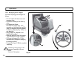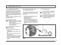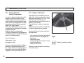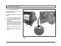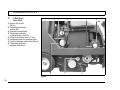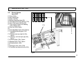
1
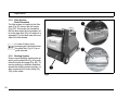
User Manual
Apex 62B
Introduction
Preface
Dear customer, It is our desire that the
good characteristics of the Apex 62 B
should justify the confidence you demonstrated by making this purchase.
Prior to the first drive, carefully read the
chapter "Safety Information” as well, in
order to ensure you a safe working with
the machine.
Your own safety, as well as the safety of
others, depends to a great extent on
how the vehicle is moved and operated.
Therefore, carefully read and understand this operation and maintenance
manual prior to the first drive.
The manual provides valuable information about operation, service and
maintenance. The warning symbols as
used in this manual identifies items relevant to safety. Please observe the
safety provisions (see chapter "Safety
Information”).
Your authorised PowerBoss dealer will
be pleased to answer further questions
regarding the vehicle or the operation
and maintenance manual.
2
Please be advised explicitly that we
cannot accept any legal issues out of
the contents of this manual.
If repair work has to be performed make
sure that only genuine spare parts are
used; only genuine spare parts may
guarantee a dependable machine.
We reserve the right for technical improvement..
Valid as of: July 2007
PowerBoss Inc.
175 Anderson Street
Aberdeen NC 28315 U.S.A.
Telephone: (910) 944-2105
Fax: (910) 944-740
Proper use
The Apex 62 B sweeper has been exclusively designed for collecting dry and
moist matter from floor surfaces in e.g.
factories, storage buildings, parking
grounds and pedestrian areas. Using
the machine beyond this scope of application will be deemed improper use;
The manufacturer cannot be held liable
for consequential damages; the user
alone bears the risk. The Apex 62 B is
not suitable for collecting toxic, combustible or other matters which are hazardous to health. The term of proper use
also includes operation, maintenance
and repair work to be performed in compliance with the manufacturer's specifications. The Apex 62 B may be used by
persons only that are familiar with the
machine and aware of possible hazards
involved. The applicable Accident Prevention Regulations and further regulations in vigour concerning aspects of
safety and working medicine will have
to be complied with. If modifications to
the machine are made in absence of
the manufacturer's prior consent, the
latter cannot be held liable for damage
resulting from such unauthorized modification.
Introduction
Notes on warranty
The terms of the sales contract apply.
Damages are not subject to warranty if
they are due to non-compliance with the
maintenance and service provisions.
The maintenance work has to be performed by an authorized PowerBoss service center and confirmed in the
"Maintenance certificate" which is the
warranty document.
The following is excluded from
warranty: fuses, natural wear, damages
caused by overload, inexpert handling
and unauthorized modification of the
machine. Moreover, any claim for warranty cannot be accepted if damages of
the machine are caused by fitting parts
or accessories without PowerBoss's
prior and explicit consent or by noncompliance with the maintenance instructions.
Acceptance of the machine
Upon arrival, check machine for possible damages in transit. For refund of
such damage, have the Deutsche Bahn
AG or your freight forwarder confirm
such damage. Mail notification and
waybill to:
PowerBoss Inc.
175 Anderson Street
Aberdeen NC 28315 U.S.A.
Telephone: (910) 944-2105
Fax: (910) 944-740
[email protected]
3
Table of Content
Introduction . . . . . . . . . . . . .
Preface. . . . . . . . . . . . . . . . . .
Proper use . . . . . . . . . . . . . . .
Notes of warranty . . . . . . . . . .
Acceptance of the machine . .
1
1.1
1.2
1.3
1.4
1.5
1.6
1.7
2
2.1
2.2
2.3
2.4
2.5
2.6
2.7
2.8
4
2
2
2
3
3
Safety information . . . . . . . . 5
Safety and Warning Symbols . 5
General Provisions . . . . . . . . . 6
Provisions for Operation. . . . . 6
Maintenance instructions . . . . 8
Specific Hazards . . . . . . . . . . 9
Information for Protection of Environment . . . . . . . . . . . . . . . 10
Labels at the Machine . . . . . 11
First Operation . . . . . . . . . . 15
Instruction. . . . . . . . . . . . . . . 15
Initial charging procedure . . . 15
Before Taking into Operation 15
Start Machine . . . . . . . . . . . . 15
Operation . . . . . . . . . . . . . . . 16
Machine
stopping and parking . . . . . . 16
After work . . . . . . . . . . . . . . . 16
Transport rides and Towing . 17
3
3.1
3.1.1
3.1.2
3.1.3
3.1.4
3.2.2
Operation . . . . . . . . . . . . . .
Working Procedure . . . . . . .
Sweeper Roller. . . . . . . . . . .
Side Broom . . . . . . . . . . . . .
Steering . . . . . . . . . . . . . . . .
Filter System
Dust Evacuation . . . . . . . . . .
Shaking System . . . . . . . . . .
Brake . . . . . . . . . . . . . . . . . .
Travel Drive Assembly . . . . .
Hydraulic System . . . . . . . . .
Operating Elements . . . . . . .
Control Panel
Apex 62 B. . . . . . . . . . . . . . .
Emtying of the Dirt Hopper. .
4
Technical Data . . . . . . . . . . 30
3.1.5
3.1.6
3.1.7
3.1.8
3.2
3.2.1
5
5.1
18
18
19
19
19
20
20
21
21
21
22
24
28
Maintenance and Care . . . . 34
PowerBoss
System Maintenance . . . . . . 34
5.2
Maintenance document . . . . 35
5.3
Maintenance Schedule. . . . . 36
5.4
Battery System. . . . . . . . . . . 41
5.4.1 Low Discharge Signal Sender .
42
5.4.2 Battery Charging Status
5.4.3
5.4.4
5.4.5
5.4.6
5.5
5.5.1
5.5.2
5.5.3
5.5.4
5.5.5
5.5.6
5.6
5.6.1
5.6.2
5.6.3
5.6.4
5.7
5.8
5.9
Indicator . . . . . . . . . . . . . . . . 43
Hourmeter . . . . . . . . . . . . . . 43
Setting Other Battery Types. 43
Plug Connection Coding . . . 44
Batterie einsetzen . . . . . . . . 46
Sweeper Unit . . . . . . . . . . . . 48
Mount/Dismount
Sweeper Roller. . . . . . . . . . . 48
Adjust Sweeping Track . . . . 49
Sealing Strips for
Broom Compartment . . . . . . 50
Replace Side Broom . . . . . . 50
Dismount Plate Filter . . . . . . 51
Basic Cleaning of Plate Filter 52
Hydraulic System . . . . . . . . . 53
Check Hydraulic
Fluid Level . . . . . . . . . . . . . . 53
Refill Hydraulic Fluid . . . . . . 54
Change Hydraulic Filter . . . . 54
Change Hydraulic Fluid . . . . 55
V-Belt Drive
Apex 62 B. . . . . . . . . . . . . . . 56
Electric System
Apex 62 B. . . . . . . . . . . . . . . 57
Special Equipment and
Spare Parts . . . . . . . . . . . . . 59
Safety information
1
Safety information
1.1
Safety and Warning Symbols
All paragraphs in this manual referring
to your personal safety, the safety of
your machine and the environment protection are attributed one of the following warning symbols:
Symbol
Hazardous for ...
Description
Safety Provisions
persons and goods
Safety Provisions in dangerous situation caused by
misuse inaccurate adherence of instructions or prescribed work routine.
CAUTION
the machine
important information on handling the machine in
order to maintain operability.
Ecological hazard
the environment
due to use of substances representing an inherent
danger to health of environment
5
Safety information
1.2
General Provisions
• Apart from the provisions contained
in this instruction manual, the general safety provisions and the accident prevention regulations as
imposed by law have to be complied
with.
• Before taking your machine into operation, carefully read the instruction
manual and comply with all points
mentioned there during work.
• Persons being trained by qualified
PowerBoss technicians only are authorised to operate, service and repair the machine.
• You are advised to thoroughly study
the safety instructions since precise
knowledge only helps avoiding errors during operation of the machine
and thus guarantee faultless usage
of the machine.
• The operating instructions have to
be at hand at the place of use of the
machine, and therefore have to be
kept readily available at the machine.
• When selling or letting the machine
for rent, hand out these documents
to the new owner/operator and have
the transfer certified!
6
• The warning and instruction plates
attached to the machine contain valuable advice about safe operation.
Immediately replace incomplete or illegible labels.
• As far as safety standards are concerned, spare have to equal genuine
spare parts!
• Keep clear of hazard zone of the
Apex 62 B.
• Only use a mobile phone when the
machine standing still.
• Passenger transport is not admitted.
1.3
Provisions for Operation
• Before taking into operation, check
the machine for operational safety!
Immediately remedy malfunctions!
• It is indispensable for the operator to
get acquainted with all attached implements and controls as well as
with their function before operation
begins. Once you have started to
work, no time will be left to do so!
• When working with the machine use
firm and skid proof shoes.
• The machine may be used only on
such surfaces clearly specified by
the owner or his authorised representative.
• When working with the machine take
notice of third persons, especially
children.
• The machine is not designed for collecting hazardous, inflammable or
explosive dusts or substances.
• This machine must not be used as
dust-evacuating machine with dust
filter insert (separator) to collect
dusts which are hazardous to health.
• Usage of the machine in explosive
areas is prohibited.
• Pull the key switch to avoid unauthorized use of the machine.
• Before commencing work, the operator has to make sure that the machine and its accessories are in proper and safe condition. Machines
with known defects must not be
used.
• Before operation of the machine, adjust driver's seat such that complete
visibility of the riding track and the
rear working area is given!
• For safety reasons, the driver's seat
is equipped with a seat contact
switch. Function of this contact
switch must not be bypassed!
• The seat contact switch will controlled electronocally. Any manipulation
Safety information
•
•
•
•
•
to result in automatically blocking of
the machine.
Disengage all drive systems before
switch-on the machine.
The machine may be started, run
and stopped by a person seated only.
Never let the machine run in indoor
areas! Intoxication hazard!
Provide for sufficient ventilation
when sweeping indoors (dust and
combustion gas).
Intoxication hazard!
Always adapt the driving speed to
the ambient conditions and the loading state.
Compared to four-wheeled vehicles,
driving stability of three-wheeled vehicles is reduced, therefor:
Abrupt steering manoeuvres at higher speed or negotiating curves at
high speed may cause tipping of the
articulated vehicle.
Do not turn at slopes but on level
ground only
Ride up- and downhill straight.
Avoid taking sudden curves when riding up- or downhill or across to the
slope.
In slope there is tilting danger.
• The machine may be used only for
operation on areas with a maximum
inclination of up to 16 %.
• Do not exceed the admissible total
weight and the admissible axle load
limits. Check the dirt hopper filling level frequently.
• Before lifting or lowering the dirt hopper make sure that no persons, animals or other obstacle are in the area
of operation.
• Pinching and shearing hazard.
Provide for required safe distance
before lifting or lowering the dirt hopper.
• It’s only allowed to lift up the dirt hopper in immediately nearness of the
container.
Emtying the dirt hopper on level and
solid ground.
• Do not sweeping when the dirt hopper is lifted.
• By emtying the dirt hopper pay attention to bystanders.
• Proceed to filter shaking only if the
dirt hopper is in closed position.
• Pay attention to hot parts for example cooling water, tubes of the exhaust etc..
7
Safety information
1.4
Maintenance instructions
• The daily and weekly maintenance
and repair task must be performed
by a qualified operator. For any
maintenance and repair work
beyond please contact your local
PowerBoss service centre.
• Observe the maintenance activities
and intervals set out in the instruction manual.
• Maintenance and repair work may
be carried out only by means of appropriate tools.
• Have the machine checked for safe
condition in the sense of the Accident Prevention Regulation by an
expert at regular intervals (recommendation: at least once yearly) as
well as after modifications or repair.
• Spare parts have to equal the technical requirements as specified by the
manufacturer! Genuine spare parts
guarantee compliance with these requirements.
• Use of other than the sweeper rollers
and side brooms approved by the
manufacturer is not admitted (see
technical data) since use of other
sweeper rollers and side brooms
may affect your safety.
8
• Use of other than the oilfilters approved by the manufacturer is not admitted (see technical data) since use
of other air- and oilfilters may affect
your safety.
• Stop machine before proceeding to
inspection and maintenance work.
Pull the key.
• Proceed to cleaning of the dirt hopper in regular intervals to preclude
formation of bacterial deposits.
• The machine is splash-proof (IPX3).
Cleaning the machine by means of
high-pressure cleaning equipment or
by vapour jet is prohibited.
• Turn off the machine before transporting them.
• After having jacked the Apex 62 B by
means of a car lifter, additionally
support the machine adequately.
• No person is allowed to be in the jakked or lifted-up Apex 62 B.
• Before changing wheels protect the
machine against rolling by placing
wedges.
Proceed to wheel changing when the
machine is on level and solid ground.
• Do not remove, install or repair a tire
on the rim. Contact a tire workshop
for works at tires and rims. Such
•
•
•
•
•
•
•
workshops have qualified personnel
as well as special safety tools at disposal.
Do not proceed to welding, boring,
sewing or grinding at the vehicle's
frame. Only PowerBoss-workshops
are authorized to replace damaged
parts.
Use genuine fuses only.Use of higher-level fuses may damage the electric system. Risk of fire.
When working at the electric system
disconnect the the battery plug.
Do not keep batteries discharged for
a longer period, always recharge
them as soon as possible.
Top with distilled water only.
Never refill battery acid in battery
cells of perfect condition.
Keep batteries dry and clean and
clear of soiling such e.g. metallic
dust to avoid leakage current.
Battery acid is highly caustic (keep
clear of children).
When checking the battery acid level, wear safety glasses. If acid
splashes get into the eyes rinse with
clear water for 15 minutes and contact a doctor immediately.
Use appropriate protective means
Safety information
•
•
•
•
•
(e.g. protective gloves or fingerstalls) when handling battery acid.
Do not use open flames (explosion
hazard).
Pinching and shearing hazard by fitting, removal and change of the battery.
All liquids escaping under high pressure (such as e.g. hydraulic liquid)
may penetrate the skin and cause
heavy injuries. Contact a doctor immediately in order to avoid infections. Take all precautions before
draining boiling oil - burning hazard.
Inspect the braking system at regular
intervals. PowerBoss-workshops or
approved brake service centres only
are authorized to proceed to adjustment or repair work of the brake system.
Inspect the hydraulic system at regular intervals. PowerBoss-workshops
only are authorized to proceed to adjustment or repair work of the hydraulic system.
Check hydraulic hoses and lines for
leakage or damages in regular intervals. Replace defective hoses and lines immediately.
1.5
Specific Hazards
Safety equipment
• Do not operate the Apex 62 B without safety equipment being installed (all cover parts of the machine).
Elektric system
• Only use genuine fuses with prescribed connecting load.
• In case of malfunction of the electric
system, immediately shutdown machine and remedy.
• Qualified personnel only is authorised to proceed to works at the electrical equipment and only according
to electro-technical rules.
• Inspect/check the electrical equipment of the machine at regular intervalls. Immediately remedy defects
such e.g. loose connections or scorched cables.
• Respect the operating instructions of
the battery manufacturer.
• Never place metal objects or tools on
batteries - short-circuit hazard!
• Provide for sufficient ventilation of
areas where batteries are charged. –
Explosion hazard!
Open seat hood by loading the batteries.
9
Safety information
1.6
•
•
•
•
•
•
10
Information for Protection of
Environment
For safe use of substances inheriting
a danger to health and environment
specific knowledge is required.
During maintenance and repair, all
ope-rating media have to be collected In adequate receptacles. Provide
for disposal in compliance with the
legal provisions according to the Waste Disposal Act and the Used Oil
Act.
Do not let leaking oil, lubricants or
other substance penetrate the soil.
Danger of ground water soiling.
Wipe away spilled fluids and provide
for disposal according to the regulations.
Depending on the filtered substances, used filter inserts are considered special waste in most cases
and have to be disposed of accordingly.
Batteries contain highly caustic sulphuric acid. Batteries have to be
handled with utmost caution. Old
batteries are considered special waste and have to be disposed of accordingly.
Used batteries labelled as recyclable
contain reusable economic goods.
According to the crossed dustbin label these batteries must not be added to the normal waste. Provide for
agreement with the PowerBoss contract dealer on return and disposal
according to § 8 BattV.
Safety information
1.7
Labels at the Machine
The following safety and information labels are legibly attached to the vehicle.
Replace missing or illegible labels immediately.
Key switch (Fig. 1/4)
High-pressure cleaner
Steam cleaner (Fig. 1/8)
PowerBoss nameplate front (Fig. 1/1)
and rear (Fig. 2/1)
Brake (Fig. 1/5)
Lifted-up disposal function (Fig. 1/9)
Vehicle identification number (Fig. 1/2)
Parking brake (Fig. 1/6)
Instruction manual (Fig. 1/3)
Folding apron (Fig. 1/7)
11
Safety information
Pinching hazard (both sides) (Fig. 2/2)
Sound power
Rise (Fig. 1/10)
Hydraulic fluid (Fig. 2/5)
Type name (Fig. 2/6)
Sweeper roller wearing take-up
(Fig. 2/3)
Adjust sweeping track side broom
(Fig. 1/11)
Rotating parts (Fig. 2/4)
Maximum speed (Fig. 1/12) and (Fig. 2/
7) (option)
8
12
Apex 62 B
Safety information
9
10
12
12
1
11
7
5
2
6
4
3
8
Fig.1
13
Safety information
1.8
6
3
2
4
1
4
7
5
Fig.2
14
First Operation
2
First Operation
2.1
Instruction
Instruction is required before first operation. First instruction into handling of
the machine must be held by a qualified
person sent by your local PowerBoss
contract dealer. Your PowerBoss dealer will be informed by the manufacturer
upon delivery of the vehicle and will
contact you to make a date for instruction.
2.2
Initial charging procedure
Before first operation of the
machine, fully charge the battery with an initial charging procedure and comply with the
operating instructions of the
charger as well as with those of
the battery manufacturer.
PowerBoss cannot be held liable for damages resulting from
the fact that the initial charging
has not or insufficiently been
done.
2.3
Before Taking into Operation
Proceed to the following inspections before taking the machine into operation:
1. Check parking site for signs of leakage. Hoses, lines and tanks must be
free from any leakage or damage.
2. Open seat hood.
3. Check charge of battery and charge
if required.
4. Close seat hood.
2.4
Start Machine
Before starting the machine
you are advised to read and
comply with the Provisions of
Operating from Safety Information chapter!
Before starting the machine, subsequently actuate the following control
elements:
1. Set all operating levers and switches
to neutral.
2. Secure the vehicle by engaging the
parking brake.
3. Turn key switch and start machine.
- After the machine has switched on,
the charge control display (TSG) is
lighting up by full charging battery.
Do not use the Apex 62 B at
ambient temperatures of more
than 40°C.
Do not switch on the machine
at temperatures of 0°C or less.
Its not possible to switch on the
machine, when the accelerator
pedal is linked.
15
First Operation
2.5
Operation
Proceed to the following to set the machine into operation:
1. Check the machine, see paragraph
2.3 - Before Taking into Operation.
2. Start vehicle, see paragraph 2.4.
In initial position, vacuuming is
activated. Use the operating
draw if the collected dirt is wet.
3. Lower sweeper roller and side
broom.
4. Release parking brake.
5. Slowly depress drive pedal until
desired speed has been attained.
6. Check filling level of the dirt hopper
and emty if required.
7. Operate shaking installation regular
for cleanig the filter.
16
2.6
Machine
stopping and parking
1. Release drive pedal which returns
automatically in neutral position and
the machine slows down.
2. Actuate parking brake.
3. Lift sweeper roller and side broom.
4. Switch machine off.
Slowing down the Apex 62 B is
possible by applying opposite
forces with the drive pedal or
by using the service brake.
When leaving the machine unattended, pull key switch in order to preclude unauthorized
use.
2.7
After work
1. Ride machine to suitable site for cleaning.
2. Stop machine, lift sweeper roller and
side boom.
3. Start shaking procedure.
4. Empty dirt hopper, see operation
chapter 3.2.2.
5. Clean machine.
Do not clean the electrical
parts by means of high-pressure cleaning equipment.
First Operation
2.8
Transport rides and Towing
Transport rides
Before transporting the Apex 62 B on
other vehicles, engage the parking brake and secure the machine by placing
wedges at the wheels and by straps on
the tie-down points front (Fig. 3/1) and
rear (both sides) (Fig. 3/2).
For safety reason, by activated
machine and by leaving the driving seat is resounding a
warning signal.
Towing
Lift up the front wheel when towing the
machine.
2
1
Fig.3
17
Operation
3
Operation
3.1
Working Procedure
General
The Apex 62 B sweeper has been exlusively designed for collecting dry and
moist matter from floor surfaces in e.g.
factories, storage buildings, parking
grounds and pedestrian areas.
4
Functional Description
The side broom (Fig. 4/1) is used to collect dirt at corners and borders and to
enlarge the working width as well as to
increase the area performance on large
surfaces.
The sweeper roller (Fig. 4/2) casts the
dirt overhead into the dirt hopper (Fig.
4/3). The collected fine dust is evacuated by the suction fan and separated by
a filter system (Fig. 4/4). The air returned into the environment is clean.
Dirt disposal at the Apex 62 B is realized via lift-up disposal (lift-up
hight>1420mm) directly into standard
waste container.
1
Fig.4
18
2
3
Operation
3.1.1 Sweeper Roller
The sweeper roller (Fig. 4/2) is equipped with 12 rows of bristles arranged in
v-shape.
The sweeper roller width amounts to
800 mm and its diameter to 430 mm.
The operator lifts and lowers is by hand
lever (Fig. 5/1).
4
1
3
3.1.2 Side Broom
The standard version, the side broom
(Fig. 5/2) is located at the front right of
the machine.The operator lifts and lowers is by hand lever (Fig. 5/3).
The swinging area of the side broom
arm is limited by stops.
For special application, fitting of a second side broom at the left side is possible.
3.1.3 Steering
Steerage is effectuated mechanically
from steering wheel to front wheel via
chain. This chain is to be re-adjusted as
required.
2
Fig.5
Any work at the steering has to
be executed by authorized
PowerBoss-service-workshop
only.
19
Operation
3.1.4 Filter System
Dust Evacuation
The filter system is located in the filter
case (Fig. 6/1) above the dirt hopper
(Fig. 6/2). The suction fan transports
the fine dust raised by the sweeper roller to the plate filter (Fig. 6/3) where it is
separated. The fine dust sets at the outside of the filter blades.
1
In case of heavy dusty
sweeping dirt, check and clean
the plate filter (Fig. 6/3) at regular intervals.
3
3.1.5 Shaking System
Due to normal working vibration the set
dust from the plate filter (Fig. 6/3) partly
falls off into the dirt hopper (Fig. 6/2). To
ensure working in a dustfree ambiance,
actuate the shaking system regulary, or
after request by the control lamp (Fig.
10/5) at the latest.
2
Fig.6
20
Operation
3.1.6 Brake
The Apex 62 B is equipped with a service brake. This brake has been constructed as shoe brake and equally
serves as parking brake. It is located in
the rear wheels and is actuated via cables. Two special adjustment screws
(Fig. 7/2) are located in front of the
chassis, behind the front cover
(Fig. 7/1).
3
Any work at the braking system
has to be executed by authorized PowerBoss-service-workshop only.
3.1.7 Travel Drive Assembly
The Apex 62 B are equipped with a
electric drive assembly.
1
3.1.8 Hydraulic System
The hydraulic system existing of hydraulic valves, hydraulic pump with hydraulic fluid tank (Fig. 7/3) and serves
the operation of the lifted-up disposal
and the suíde broom.
2
Fig.7
21
Operation
3.2
1
2
3
4
5
6
7
8
Operating Elements
Actuator for folding apron
Service brake lock
Service brake / parking brake pedal
Drive pedal, reverse
Drive pedal, forward
Control panel
Seat adjustment
Lever for dirt hopper
(lifting-lowering-swinging)
6
6
7
5
3
Fig.8
22
2
1
8
4
Operation
Actuator for folding apron (Fig. 8/1)
To open and close the folding apron for
collecting coarse dirt during sweeping
drive.
Drive pedal, reverse (Fig. 8/4)
To change direction to reverse ride with
contineous regulation of riding speed at
the same time. If the driver releases the
pedal it returns to initial position and the
machine slows down to standstill.
Service brake / parking brake lock
(Fig. 8/2)
To lock the service brake / parking brake. Operate pedal and fix with lock. The
service brake is working then as parking brake. The lock released by pushing service brake pedal (Fig. 8/3).
Control panel (Fig. 8/6)
Refer to chapter „Control Panel“.
Service brake / parking brake pedal
(Fig. 8/3)
Serves for operating the sevice brake
on the rear wheels. Simultaneously actuate service and parking brake before
leaving the machine.
Seat adjustment (Fig. 8/7)
To adjust the seat position to drivers of
different height. Adjust the seat so as to
allow the driver being comfortably seated and attaining all elements required
for operation.
- Adjust seat lengthwise:
push lever slightly to the right and
displace seat forwards or backwards to the required position.
Then let the lever catch again.
Drive pedal, forward (Fig. 8/5)
To change direction to forward ride with
contineous regulation of riding speed at
the same time. If the driver releases the
pedal it returns to initial position and the
machine slows down to standstill.
Lever for dirt hopper (Fig. 8/8)
(lifting-lowering-swinging)
Lever for lifting-lowering-swinging the
dirt hopper.
For lifting and lowering pull simultaneously lever for release of lifted-up disposal function (Fig. 9/1).
Swinging follows without operating of
the lever (Fig. 9/1).
Simultaneously actuate lever for release of lifted-up disposal function, lever for sweeper roller (see chapter
„Control Panel“), he serves releasing
the dirt hopper for lifting and lowering.
Swinging of the dirt hopper without lever for release for lifted-up disposal
function.
23
Operation
3.2.1 Control Panel
Apex 62 B
1 Sweeper roller lever
and release of lifted-up disposal
function
2 Side broom lever
or rather for side broom and
sweeper roller
3 Suction fan / shaking system knob
4 Control lamp, shaking system
5 Control lamp, direction indicator
(Option)
6 Hourmeter /
Charge control display (TSG)
7 Control lamp, parking brake
8 Horn
9 Key switch
10 Indicator lever (Option)
11 Lighting (Option)
12 Warning light (Option)
13 Rotating beacon (Option)
14 Side broom left (Option)
6
2
1
7
4
5
10
8
11
14
13
12
3
9
Fig.9
24
Operation
Sweeper roller lever
and lifted-up disposal (Fig. 9/1)
Two-Hand-Operation.
For lifting, lowering, swinging, to switch
on and off the sweeper roller and to release of lifted-up disposal.
- Sweeper roller lowering and switch
on = push lever
- Sweeper roller lifting and switch
off = pull in middle position
- Release of lifted-up disposal
function = pull lever
(see chapter „Emtying of the Dirt Hopper“).
Lifting and turn off the sweeper
roller, if the lever for the right
side broom is in lifting position.
Side broom lever (Fig. 9/2)
To lift and lower the side broom or lower
and turn on the side broom and
sweeper roller in one process (Fig. 9/1).
- Lower side broom = push lever.
- Lift side broom = pull lever.
Suction fan / shaking system
(Fig. 9/3)
Knob position
(from bottom to top):
0
Activated vacuuming function
1
Deactivated vacuuming function
2
Shaking system ON
(pull knob to stop and then release)
If the yellow control lamp (Fig. 9/5)
lights actuate the shaking system (position 2).
In this position, the shaking system is
operable and proceeds to jolting in 7 repeated intervals.
25
Operation
After jolting, the knob is to be
kept in position 1 for about 25
seconds.
Control lamp, shaking system
(Fig. 9/4)
Proceed to jolting of the filter system
upon lighting of this control lamp by actuating the knob (Fig. 9/4) in position 2.
The control lamp flashes during the shaking procedure and
extinguishes after filter has
been cleaned.
Jolting is effectuated in 7 intervals.
26
Control lamp, direction indicator
(Option) ((Fig. 9/5)
Indicate, if using the indicator lever, the
direction.
Hourmeter
Charge control display (TSG)
(Fig. 9/6)
Indicates the operating hours. The
counter works only if the driver is seated and the machine is running.
Charge control display see chapter 5.4
Battery System.
Control lamp, parking brake
(Fig. 9/7)
Lights upon actuation of the parking
brake. Extinguishes upon release of the
parking btake.
Horn (Fig. 9/8)
An acoustic signal sounds upon actuation of this button.
Operation
Key switch (Fig. 9/9)
To switch on and off the machine and to
secure it against unauthorised use.
Warning light (Option)
(Fig. 9/12)
Use this switch by a technocal defect, if
is impossible to move the machine.
Lighting flashes ON/OFF.
For safety reason, by activated
machine and by leaving the driving seat is resounding a
warning signal.
Indicator lever (Option) (Fig. 9/10)
Indicate changing of direction
- Lever down = to left.
- Lever up = to right.
Side broom left (Option)
(Fig. 9/14)
For special application, fitting of a second side broom at the left side is possible.
- Switch actuate = side broom lowering and turning on.
Switch not actuate = side broom lifting and is laying up.
Rotating beacon (Option)
(Fig. 9/13)
To switch the rotating beacon ON/OFF.
Lighting (Option) (Fig. 9/11)
To switch the driving headlight ON/
OFF.
27
Operation
3.2.2 Emptying of the Hopper
Proceed to emptying of the hopper as
follows:
• Lift and switch off side broom and
sweeper roller.
• Proceed to shaking of the filter system.
• Lift hopper as follows:
Pull lever for hopper (Fig. 10/1)
upwards and simultaneously pull the
lever for sweeper roller and release
for lifted-up disposal (Fig. 10/2) in arrow direction.
• Bring hopper for disposal in suitable height position.
• Back the Apex 62 B until the hopper
is positioned above the container.
• Pull lever for hopper (Fig. 10/1) in
arrow direction, hopper is swinging
in emtying position.
• Forward the Apex 62 B after complete
emptying.
Caution by driving away, if dirt
hopper is towering in the container:
Hazard of damaging!
28
Fig.10
2
1
Operation
• Lower hopper as follows:
Pull lever for dirt hopper (Fig. 10/1)
down and simultaneously pull the lever for sweeper roller and release for
lifted-up disposal (Fig. 10/2) in arrow
direction.
• The hopper is swinging automatically in starting position by lowering.
• Hopper is again in working position.
The operation of lifted-up disposal function is blocked as
long as sweeping function is
ON.
Do not switch on sweeper roller when hopper lifting out.
Riding with the lifted hopper reduces stability of the machine significanty. For this reason, do not lift the hopper
but just before emtying.
Before lifting the hopper,
the operator has to make sure
that no persons or objects are
behind or next to the machine.
Stop the machine on level
ground before lifting the
hopper.
When the hopper is lifted,
the operator has to ride the
machine slowly.
Keep clear of the hazard zone!
Pinching and shearing hazard.
Provide for required safe distance before lifting or lowering
the hopper.
The hopper is approved
only for max. filling of 130 litres
but not more than a weight of
220 kg.
Do not move the machine during the lifting procedure.
Clean the hopper in regular
intervals.
29
Technical Data
4
Technical Data
Dimensions and weights
Length with side broom
Width without side broom
Width with 1 side broom
Width with 2 side brooms
Height above driver’s seat
Dead weight
Admissible total weight
Driving and sweeping performance
Forward speed
Reverse speed
Sweeping speed up to (4 km/h recommended)
Sweeping track w/o/with 1 side broom
Sweeping track with 2 side brooms
Theoretical sweep. perf. with 1 or 2 side brooms
Theoretical sweep. perf. without side broom
Gradability (max. 1 min)
30
mm
mm
mm
mm
mm
kg
kg
1998
1142
1142
1142
1520
735
1395
km/h
km/h
km/h
mm
mm
m² / h
m² / h
%
0-8
0-4
8,0
800 / 1150
1470
9200/11700
6800
16
Technical Data
Filter system
Filtering surface
Plate filter
Sweeper roller
Length / diameter
Wearing limit
Speed
Sweeping track
Quantity of bristle rows
Serial bristling
Ground clearance of sealing
Sealing strips, left / right / rear
Sealing strip, front
Side brooms
Diameter
Speed
Serial bristling
m²
peaces
5,0
1
mm
mm
1/min
mm
800 / 430
350
500+/-20
50+10
12 v-shaped
PES
mm
1/1/4
lying on the bottom
mm
1/min
600
85+/-4
PES
31
Technical Data
Debris hopper
Hopper capacity
litre
130
Drive wheels
wheel front, solid rubber tires
Wheel bandage:
D=300/B=100
Solid rubber tires (rear)
4.00-8
Hydraulic system Travel drive assembly
Haydraulic fluid, e.g. Mobiloil
Hydraulic tank, capacity
Fluid filter cartridge
Electric system
Supply voltage
Drive (recirculated capacity)
Drive of sweeper roller (recirculated capacity)
Drive of side broom (recirculated capacity)
Drive of exhaust fan (recirculated capacity)
Degree of protection against infiltration of water
32
litre
order-no.
V
KW
KW
KW
KW
DTE 15 M
(or an equivalent oil)
13
01133510
24
1.875
1.25
1.25
1.25
IPX3
Technical Data
Noise emission
The sound pressure level (LpA) measured according to DIN IEC
60335-2-72 and under standard operating conditions at the operator’s ear amounts to:
The sound power level (LwA) measured according to DIN IEC
60335-2-72 under standard operating conditions and maximum
volume flow amounts to:
dB (A)
71
dB (A)
88
33
Maintenance and Care
5
Maintenance and Care
General
Before proceeding to maintenance and care work you are
advised to read and comply
with the Safety Information
chapter!
Compliance with the recommended
maintenance works will give you the
certitude of always having a reliable
machine at disposition.
Daily or weekly maintenance and repair
works may be executed by the driver/
operator having been trained accordingly. Further PowerBoss system maintenance works have to be executed by
qualified personnel only. Please contact
your local PowerBoss Service Centre or
PowerBoss contract dealer. We cannot
be held liable for damages resulting
from non-compliance with these instructions.
Please indicate the machine's serial
number with any enquiry or spare part
order, see paragraph 1.7 - Nameplate.
34
5.1
PowerBoss
System Maintenance
The PowerBoss System Maintenance:
• guarantees reliable operability of the
PowerBoss machines (preventive
maintenance)
• minimizes operating costs, repair
costs and maintenance costs
• ensures long service life and operability of the machine
The PowerBoss System Maintenance
is structured in separate modules and
determines specific technical works to
be executed as well as the intervals for
such maintenance works. For any specific maintenance type, the replacement
parts are determined and listed in spare
part kits.
PowerBoss-System Maintenance K:
To be performed by the customer in accordance to the maintenance and care
instructions contained in the operating
instructions (daily or weekly). The
driver/operator will be instructed upon
delivery of the machine.
PowerBoss-System Maintenance I :
(after 50 hours of operation - einmalig)
To be performed by qualified personnel
of authorised PowerBoss Service Centre.
PowerBoss-System Maintenance II:
(every 125 hours of operation)
To be performed by qualified personnel
of authorised PowerBoss Service Centre in accordance with the machine-specific system maintenance including
spare part kit.
PowerBoss-System Maintenance III:
(every 250 hours of operation)
To be performed by qualified personnel
of authorised PowerBoss Service Centre in accordance with the machine-specific system maintenance including
spare part kit.
PowerBoss-System Maintenance S:
(every 500 hours of operation safety
check)
To be performed by qualified personnel
of authorised PowerBoss Service Centre in accordance with the machine-specific system maintenance including
spare part kit. Execution of all safety-relevant inspections according to UVVBGV-TÜV-VDE as prescribed by law.
Maintenance and Care
5.2
Maintenance document
Handing over
Upgrade
Test drive
Handing over to the customer
Instruction
carried out on:
PowerBossSystem-Maintenance I
50 operating hours
PowerBossSystem-Maintenance II
125 operating hours
PowerBossSystem-Maintenance III
250 operating hours
Workshop stamp
Workshop stamp
Workshop stamp
carried out on:
carried out on:
carried out on:
at _________________ operatin hours
at _________________ operatin hours
at _________________ operatin hours
at _________________ operatin hours
PowerBossSystem-Maintenance II
375 operating hours
PowerBossSystem-Maintenance III+S
500 operating hours
PowerBossSystem-Maintenance II
625 operating hours
PowerBossSystem-Maintenance III
750 operating hours
Workshop stamp
Workshop stamp
Workshop stamp
Workshop stamp
carried out on:
carried out on:
carried out on:
carried out on:
at _________________ operatin hours
at _________________ operatin hours
at _________________ operatin hours
at _________________ operatin hours
PowerBossSystem-Maintenance II
875 operating hours
PowerBossSystem-Maintenance III+S
1000 operating hours
PowerBossSystem-Maintenance II
1125 operating hours
PowerBossSystem-Maintenance III
1250 operating hours
Workshop stamp
Workshop stamp
Workshop stamp
Workshop stamp
carried out on:
carried out on:
carried out on:
carried out on:
at _________________ operatin hours
at _________________ operatin hours
at _________________ operatin hours
at _________________ operatin hours
35
Maintenance and Care
5.3
Maintenance Schedule
PowerBossSystem Mainten. Customer
The following maintenance works are to
be performeded by the customer.
Interval
Discription of task
daily
36
Check dirt hopper (dustbin), and empty if required
o
Operate shaking system
o
Test drive and function test
o
Maintenance and Care
PowerBossSystem Maintenance Customer
The following maintenance works are to
be performeded by the customer.
Interval
Discription of task
weekly
Check acid level, fill up distilled water if required (by end of charge only)
o
Dirt hopper: Check sealing and replace if required
o
Check sweeper roller for wearing or foreign particles, re-adjust or replace if required
o
Check electrical system
o
Check hydraulic fluid level, refill if required
o
Check side broom for wearing, re-adjust and replace if required
o
Check folding apron for wearing and damaging, re-adjust and replace if required
o
Visual check of engine and hydrailic system for oil leakage
o
Clean machine
o
Test drive and function test
o
37
Maintenance and Care
PowerBoss-System Maintenance I
The following maintenance works are to
be performeded by authorized PowerBoss-Service-Centre.
Interval
Discription of task
after 50 hours of operation (uniquely)
38
Check sealings at filter system
o
Visual check of V-belts
o
Check hydraulic fluid filter and refill fluid
o
Check optical condition of machine
o
Test drive and function test
o
Maintenance and Care
PowerBoss-System Maintenance II
The following maintenance works are to
be performeded by authorized PowerBoss-Service-Centre.
Interval
Discription of task
every 125 hours of operation
Clean battery terminals
o
Check service/parking brake and re-adjust if required
o
Check hydraulic fluid level
o
Check sweeping track and adjust if required (main- and sidebrush)
o
Check brush apron and adjust if required or change
o
Check sealings at filter system
o
Check V-belt for wearing and correct tension and re-adjust if required
o
Basic cleaning of the plate filter
o
Check optical condition of machine
o
Test drive and function test
o
39
Maintenance and Care
PowerBoss-System Maintenance III
The following maintenance works are to
be performeded by authorized PowerBoss-Service-Centre.
Interval
Discription of task
every 250 hours of operation
40
Perform maintenance works according to PowerBoss-System Maintenance II
o
Check tension of steering chain and adjust tension if required
o
Check tread of wheels
o
Change plate filter
o
Check lifted-up disposal function (2-hand-operation)
o
Check hydraulic hoses and replace if required
o
Check function of seat contact switch
o
Check cables and plugged connections for damages and tight fit
o
Check carbon brushes of the electric motor for free movement and wearing, cleanse
of motor from coal dust and change carbon brushes if required
(PowerBoss Service Centre)
o
Maintenance and Care
PowerBoss-System Maintenance S
(Safety check)
The following maintenance works are to
be performeded by authorized PowerBoss-Service-Centre at least once yearly.
Interval
Discription of task
every 500 hours of operation
Perform maintenance works according to PowerBoss-System Maintenance II and III
o
Change hydraulic fluid and filter
o
Check fixing screws (brake, steering wheel and lifted up disposal) and tighten if
required (Safety check)
o
Check braking system (Safety check)
o
Check steering wheel (Safety check)
o
Test drive and function test of safety components
o
41
Maintenance and Care
5.4
Battery System
Befor commencing any work
on the electric system disconnect the battery plug.
Do not use open flames when
handling batteries and especially when checking zhe battery
acid level. Provide for sufficient
ventilation in rooms where batteries are charged. Spilled
(straight) battery acid must not
get into the sewage system before having been neutralised.
Comply with the regulations
imposed by law and observe
local prvisions.
Open the hood before charging batteries; explosive gases
may accur during the charging
procedure.
42
Maintenance and Care
5.4.1 Low Discharge Signal Sender
3
1
4
2
5.4.2 Battery Charging Status
Indicator
Upon turning ON by key switch, battery
charging status is shown by display of
green bars (Fig. 11/1). As the battery discharge during operation, the lighting
green bars extingguish one after
another showing thus always the current charge status of battery charge.
Flashing of the last two green bars (Fig.
11/3) indicates that operation will be
stopped soon. In order to preclude low
discharge of batteries, the sweeping
units are switched off and riding speed
reduced to 50% if battery is dischrage.
The red LED (Fig. 11/4) than flashes
5.4.3 Hourmeter
The operating hours of the machine appear in the display (Fig. 11/2); the hourmeter will count only during working or
transport ride; only full hours are displayed.
5.4.4 Setting Other Battery Types
Have the low discharge signal
sender set to other battery types by qualified personnel only
and in approved qualified
workstations only.
Fig.11
The factory setting is as follows:
tray battery 420 Ah EPzS.
43
Maintenance and Care
1 Voltage coding is the same for all
plugs and socket
2 Coding pin colour in the machine =
yellow
3 Coding pin colour
5.4.5 Plug Connection Coding
The battery plugs of the machine, the
battery and the stationary charger unit
have to be coded according to the battery type and the nominal voltage with
coloured pins.
The charger unit’s plugs are/will be coded in the factory according to the characteristics curve and changing the
characteristic curve (according to the
battery type ) always requires modification of the plug coding.
Plug case of charger unit:
- grey for wet batteries
- green for maintenance-free Gel
batteries
Machine plug case:
- yellow for both battery types
Battery socket case:
- grey for wet batteries
- green for maintenance-free Gel
batteries
44
Nominal voltage value for
plug printed on each side
of the hexagon (letters
upside down)
Inscription for
nominal voltage
for sockets
accordingly
Remove the coding pin by pressing the
ends together by means of pliers.
Press together for assembly.
Insert pin such that the nominal voltage
inscription is visible through the case
window. Socket and plug always with
the same nominal voltage.
The following three requirements have
to be met:
Before first operation of the
machine, the batteries have to
be adequately charged by an
initial charging procedure.
Please observe the instruction
of the charger unit’s operating
manual.
PowerBoss rejects any claim
for warranty on battery damges
caused by unfulfilled initial
charging.
Maintenance and Care
45
Maintenance and Care
nect charger plug and device plug for
electrical connection (Fig. 13/1) .
5.4.6 Batterie einsetzen
• Turn engine off and pull key.
• Secure machine by engaging the
parking brake.
• Fold back seat hood.
• Insert batteries into the battery tray
from the top.
(Fig. 12/)
Now the Apex 62 B is operable.
If the battery type setting at the
LDS should be incorrect, have
the setting modified by qualified pesonnel in an approved
workshop.
Fig.13
6 V/240 Ah, GiV maintenance-free
Fig.12
46
• Connect batteries and enclosed cable set according to (Fig. 13/) (check
for tight seating) and grease poles.
• Check set battery type at the low discharge signal sender or set if required.
• Connect charging plug of the battery
connection cable and cable of the
charger unit and proceed to initial
charging.
• After charging of the batteries, con-
Maintenance and Care
• Turn machine off and pull key.
• Secure machine by actuating parking brake.
• Fold up seat hood.
• Insert battery.
• Connect charging plug of the battery
connection cable and cable of the
charger unit and proceed to initial
charging.
• After charging of the batteries, connect charger plug and device plug for
electrical connection.
If the battery type setting at the
LDS should be incorrect, have
the setting modified by qualified pesonnel in an approved
workshop.
Fig.14
24 V/420 Ah tray battery, EPzS mit
Aquamatik
Use admitted lifting and transport devices such as e.g. lifting
tackles according to VDI 3616.
Make suer that lifting hooks do
not demage cells, connectors
or connecting cables.
47
Maintenance and Care
5.5
Sweeper Unit
2
5.5.1 Mount/Dismount
Sweeper Roller
3
4
The sweeper roller is accessible from
the left side of the machine and is to be
dismounted as follows:
• Lower sweeper roller
• Pull key switch and protect by engaging parking brake.
• Open locks (Fig. 15/1) by enclosed
square spanner (turn counter-clockwise).
• Remove cover (Fig. 15/2).
• Loosen star-shaped knob (Fig. 15/3)
and remove.
• Remove sweeper roller seating (Fig.
15/4).
• Turn handle (Fig. 15/5) upwards and
unlock.
• Remove plate with sealing strip (Fig.
15/6).
• Remove sweeper roller (Fig. 15/7)
by pulling.
1
5
For mounting the sweeper roller proceed in inverse order.
Fig.15
48
6
5
7
Maintenance and Care
5.5.2 Adjust Sweeping Track
An adjustment device allows adaption
to different sweeping conditions. The
sweeper roller has to be adjusted for
normal use and with regard to a low degree of wearing as described in the following.
Check the sweeper adjustment on level
ground as follows:
Before checking:
Mark level surface for checking
sweeper adjustment by chalk
(1000 x 300 mm).
Drive sweeping roller over underline floorspace.
• Check sweeping track
The sweeping track width is to be
70 mm with the Apex 62 B.
With one full turn of the knob,
the track widens or broadens
by approx. 10mm.
The sweeping track width can be adjusted at the star-shaped knob (Fig. 16/1)
as follows:
•
•
•
•
When exeeding the sweeping
tack width the sweeper roller
wearing increases as well as
the load of the drive.
Stop machine and pull key switch.
Engage parking brake.
Open seat hood.
Turn star-shaped knob (Fig. 16/1)
to the left = wider sweeping tack
to the right = smaller sweeping track
(Sweeper adjustment sticker (Fig.
16/2)
1
2
Check inflation pressure of tyres (6bar).
Air tyres only.
• Secure machine by engaging parking brake.
• Lower sweeper roller and let it run
dry.
• Lift sweeper roller and forward the
Apex 62 B a bit.
With the correct sweeper adjustment
the prallel sweeping marks have to
be appear on the floor (sweeping
track).
Fig.16
49
Maintenance and Care
5.5.3 Sealing Strips for
Broom Compartment
In order to assure good function of the
sweeper, a perfect condition of the
sealing strips is required, especially in
order to attain the prescribed low pressure in the broom compartment, a clean
sweeping result and the less possible
wear of the sealing strips.
Check the sealing strips of the broom
compartment for wearing and damages
in regular intervals.
Replace defective sealing strips.
The ground clearance of the lateral and
rear sealing strips is adjustable (oblong
holes in the sealing strips).
Ground clearance:
sides approx. 1mm
rear approx. 4mm
Proceed to adjustment with an inflation
pressure of the pneumatic tyres of 6
bar. Height of the front sealing strip (folding apron) cannot be adjusted. Being
dragged, it has contact with the floor.
50
5.5.4 Replace Side Broom
The side broom is located at the front
right of the machine (standard version).
Use the lever (chapter 3.2.1, Fig. 10/2)
to lift and lower the side broom.
The swinging area of the side broom is
limited by stop screws.
The side broom is driven by hydraulic
engine.
Fitting of a second side broom (left side)
for specific appliances is possible.
1
Proceed as follows for dismounting of
the side broom:
• Turn machine off and pull key switch.
• Secure machine by engaging parking brake.
• Side broom lifted.
• Loosen hexagonal nut (Fig. 17/1) below the side broom.
• Remove side broom.
Proceed in inverse order for mounting
of the side broom.
Fig.17
Check for correct mounting.
Maintenance and Care
5.5.5 Dismount Plate Filter
Proceed as follows for dismounting of
the plate filter:
• Turn machine off and pull key switch.
• Secure machine by engaging parking brake.
• Open quick-release locks (Fig. 18/1)
and remove cover (Fig. 18/2).
• Remove cover (Fig. 18/3) of the filter
installation.
• Loosen wing screws, four peaces,
(Fig. 18/4) and remove.
• Fold back frame (Fig. 18/5) and hook
frame (Fig. 18/5) at indicated position by rubber fastening (Fig. 18/6).
• Remove plate filter (Fig. 18/7).
3
2
1
4
4
6
For mounting of plate filter proceed in
inverse order.
Clean filter area.
Check plate filter of damaging.
Watch for direction of the air on
the plate filter.
Check for correct fit of the plate
filter in the machine frame.
5
5
7
Fig.18
51
Maintenance and Care
5.5.6 Basic Cleaning of Plate Filter
1
Hold the plate filter (Fig. 19/1) in vertical
position and drop it drom a height aof
approx. 1m to the even floor as represented in (Fig. 19/).
The soiled side of the plate filter points to the bottom.
Soiled side
Clearance approx. 1m
Floor
Fig.19
52
Maintenance and Care
5.6
Hydraulic System
The hydraulic units are aoi- and maintenance-free. The hydraulic oil and filter
concerned my maintenance work only.
Premature failure can be prevented by
regular inspection and periodical
maintenance according to maintenance
schedule.
We recommend having all
other works at the hydraulic system done by a authorized
PowerBoss-service-workshop.
3
2
1
3
1
5.6.1 Check Hydraulic
Fluid Level
• Turn machine off and pull key switch.
• Secure machine by engaging parking brake.
• Open quick-release locks (Fig. 20/1)
and remove cover (Fig. 20/2)
• Clean the area of the dipstick (Fig.
20/3).
• Pull dipstick (Fig. 20/3).
• Wipe dipstick by means of cloth.
• Put in dipstick until stop.
Max
Min
Fig.20
53
Maintenance and Care
• Pull dipstick (Fig. 20/3) and check
the hydraulic fluid level, refill if required.
5.6.2 Refill Hydraulic Fluid
• Unscrew cap with dipstick (Fig. 20/2)
and check hydraulic fluid level, siehe
Abschnitt 5.6.1.
• Use appropriate oil-resistant recipient with mouth or funnel for refilling.
• Proceed to check of fluid level after
refilling.
• The hydraulic fluid level must not fall
below the minimum. It should read
between the minimum and the maximum (Fig. 20/).
54
5.6.3 Change Hydraulic Filter
Change the hydraulic filter according to
maintenance schedule.
1
For change hydraulic filter proceed as
follows:
• Turn machine off and pull key switch.
• Secure machine by engaging parking brake.
• Open seat hood, loosen and remove
the wing screws of the left side cover.
• Turn hydraulic filter (Fig. 21/1) counter-clockwise to loosen it and unscrew.
• Before screwing new filter, fill it with
oil.
• Ride the machine a short distance.
• Refill sufficient hydraulicoil.
• Check fluif filling level.
Fig.21
Maintenance and Care
5.6.4 Change Hydraulic Fluid
Change the hydraulic fluid according to
maintenance schedule.
For change hydraulic fluid proceed as
follows:
• Move up the dirt hopper (Fig. 22/1).
• Turn machine off and pull key switch.
• Secure machine by engaging parking brake.
• Place recipient under the drain plug
(Fig. 22/2), drain plug is located underneath the hydraulic case (Fig. 22/
3), and remove drain plug (Fig. 22/
2).
• Turn in the screw, observe of the Oring.
• Refill hydraulic fluid, siehe Abschnitt
5.6.2
3
1
2
Fig.22
55
Maintenance and Care
5.7
V-Belt Drive
Apex 62 B
2
7
4
3
1) Suction fan V-belt
(75 Hz)
2) Tensioning device for
suction fan
3) Hydraulic pump B-belt
4) Tensioning device for
hydraulic pump (150 Hz)
5) V-belt for sweeper roller (75 Hz)
6) Tensioning lever for sweeper roller
7) V-belt for sweeper roller drive (90 Hz)
8) Tensioning device for
sweeper roller drive
1
Fig.23
56
6
5
8
Electric System
Apex 62 B
F1 Drive(160A)
F2 Key switch(15A)
F3 Drive unit(10A)
F4 Battery charging status (5A)
F5 Horn/Side broom left (Option) (7.5A)
F6 Horn Side broom (Option) (2A)
F7 Filter control/Control unit Shaking
motor (Option) (5A)
F8 Dust fan (30A), Option
F9
F10 Floodlight/Rear light (10A) (Option)
F11 Floodlight/Warning light (11A)
(Option)
F12 Parking- and rear light left (5A),
Option
F13 (Parking- and rear light right (5A),
Option
F14 Warning light (10A), Option
F15 Braking light (7.5A), Option
F16 Shaking motor (35A)
F17
F18 Sweeper roller motor (63A)
F19 Fan/lifted-up disposal motor (63A)
F 10
F 11
F 12
F 13
F 14
F 15
F 16
5.8
F2
F3
F4
F5
F6
F7
F8
Maintenance and Care
F18
A
F19
F1
Fig.24
57
Maintenance and Care
K1 Main protection Drive
K2 Control circuit
K3 Sweeper roller motor
K4 Suction fan motor/Lifted-up disposal
K5
K6
K7On-delay Filter control
K8 Shaking motor
K9 Electric lighting (Option)
K10 Flashing light relay (Option)
K2
K3
K9
Battery plug (Fig. 24/A)
K4
Fig.25
58
K1
K7
K8
K10
Maintenance and Care
5.9
Special Equipment and
Spare Parts
Designation
Description
Order no..
Protective roof
For Apex 62 B
6304
Side broom system left
With deflector plate, without brush
6315
Rotating beacon
For mounting on the protective roof
6307
Rotating beacon
For direct fitting
6308
High-Performance Filter
Superfine filter with special coating for dust-free sweeoing in problematic areas
Comfort seat
Seat features adjustable cushioning
7093
Solid rubber tyres
Set of punture-safe SE-Superelastic-tyres 4.00-4
(2 rear wheels on rim)
6334
Solid rubber tyres
Set of punture-safe SE-Superelastic-tyres 4.00-4,
leaving no traces (2 rear wheels on rim)
6335
Lighting system
Front light (according to german StVZO)
6341
Lighting system
according to german StVZO, 24V
6310
Technical Control Board Certificate
according to german TÜV
9022
Sweeper roller
Polyester bristling
6318
Sweeper roller
Polyamid bristling
6312
Side broom
Polyester bristling
6415
see spare part
cataloque
59
Maintenance and Care
60
Designation
Description
Order no..
Side broom
PES bristling (PA 2)
6423
Side broom
PES bristling (PA 1.5)
6414
61
PowerBoss Made Simple Limited Warranty
PowerBoss, Inc. warrants to the original purchaser/user that this product is free from defects in workmanship and materials under
normal use. PowerBoss will, at its option, repair or replace without charge, parts that fail under normal use and service when operated and
maintained in accordance with the applicable operation and instruction manuals.
All warranty claims must be submitted through and approved by factory authorized repair stations.
This warranty does not apply to normal wear, or to items whose life is dependent on their use and care, such as belts, cords,switches, hoses,
rubber parts, electrical motor components or adjustments. Parts not manufactured by are covered by and subject to the warranties and/or
guarantees of their manufacturers. Please contact PowerBoss for procedures in warranty claims against these manufacturers.
Special warning to purchaser -- Use of replacement filters and/or prefilters not manufactured by PowerBoss or its designated licensees, will void
all warranties expressed or implied.
A potential health hazard exists without original equipment replacement.
All warranted items become the sole property of PowerBoss or its original manufacturer, whichever the case may be. PowerBoss
disclaims any implied warranty, including the warranty of merchantability and the warranty of fitness for a particular purpose.
PowerBoss assumes no responsibility for any special, incidental orconsequential damages.
This limited warranty is applicable only in the U.S.A. and Canada, and is extended only to the original user/purchaser of this product. Customers
outside the U.S.A. and Canada should contact their local distributor for export warranty policies. PowerBoss is not responsible for costs or repairs
performed by persons other than those specifically authorized by PowerBoss. This warranty does not apply to damage from transportation,
alterations by unauthorized persons, misuse or abuse of the equipment, use of non-compatible chemicals, or damage to property, or loss of
income due to malfunctions of the product.
If a difficulty develops with this machine, you should contact the dealer from whom it was purchased.
This warranty gives you specific legal rights, and you may have other rights which vary from state to state. Some states do not allow the exclusion
or limitation of special, incidental or consequential damages, or limitations on how long an implied warranty lasts, so the above exclusions and
limitations may not apply to you.