1
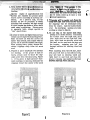
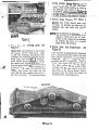
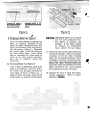
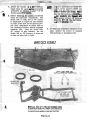
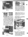
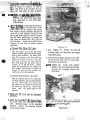
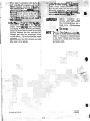
rator:
H40, H44 ana
I
Rotary Mlowel
Win. Form
No. 9-35292
.
I
- -
,
.
INT RODUT""'"
>
I
The Model H40 Rotary Mower is designed
to mount on model 220 and 222 compact
tractors above serial - number 9646800.
Model H44 Rotary Mowers mount on models
220, 222, 442 and 444 tractors above serial
number 9646800. The model H46 Mower
will mount on the same tract01rs as the
b H44, However, ft Es not recc~mmended
mode1
for 1Be mod el 220. Thest? mawe:rs can be
mounted on Model 220 and 222 tractors
prier to serial number 9646800 by using the
Model H38 Adapter Kit. The Model R39
Adapter Kit is required to mount these
mowers on Model 442 and 444 compact
tractors prior to serial number 9648800.
The Adapter Kits are available as optional
equipment.
,
- -
Model H6d Mowers, serial number C30848
and above and H46 Mowers, serial number
D30733 and above will mount on the Model
644 Wheel Loader without any changes as
e.upIahed in the Installation section of this
manual.
hIowers prior to these serial
numbers require two new lift Iinks, part
number C18315, which can be ordered through
service parts.
LIFT LEVER
Model H44 Mowers, serial number C30848
and above and H46 1klowers,, serial number
D30733 and a b v e will mount on the Model
646 W e e l b a d e r by using Drive Belt, part
number C13184, available through service
parts. Mowers prior to these serial numbers
also require two neut lift links, part number
C18315, which can be orderedl through service
parts.
.-
This manual covers recornrr
lperating
procedures, safety suggestio
stments,
mafnt enance information, ana mstarlation ins h c t i a n s . Read this manual carefully before operating your rotary mower. Your
J I Case Compact Tractor Dealer is well
qualified to answer any further questions
you might have concerning your rotary
mower. Also, if the need should arise,
his Service Department with factory trained
technicians, genuine Case repIacement parts
and the required facilities is in a posiBon
to provide proper repairs i n the shortest
time possible,
*
f -
1
w
TRAVEL LEVER
EPTH CONTROL
4
AI? JUSTING CRANK
WHEELS
Figure 1,
.
.,
Always make certain the tractor attachment
drive clutch is disengaged before s t a w
the engine and when transporting the rotary
mower.
, definitions "Right, Left, Front WIU nzd
as used throughout this manual relate to the
tractor and rotary mower as the operator is
seated f a c i n ~forward in the normal operatingpositionI-on the tractor
v r c n A f lNG CONTROLS
knob. See inset photo, F i g h e 1, Generally
best performance is obtained with the transmission in " b w " range and the engine running approximately 314 throttle. The throttle
shodd be set as low as practical t o obtain
maximum fuel eCOndllly but high enough te
prevent erigine lug-down or labor which could
cause overheating and poor mowing. Adjust the tractor ground speed with the Travel
lever according to your mowing conditions.
The principle components and controIs of
your rotary mower are identified in Figure
1 with the same description used throughout this manual.
All controls are conveniently located near
the operator's position on the tractor. The
mower bIades are placed in motion by engazing t h e tractor attachment drive clutch
lever,
The desired mowing height can be
quickly adjusted with the height selection
OPERATING 5AF ETY SUGGESTIONS
LOOK
FOR THIS 5Y MBOL
7. Maintain your tractor and rotary mower
in top operating condition.
TO FOlNT OUT IMPORTANT
8. Never get on or off the tractor whiie
mower is running,
SAFETY PRECAUTIONS
9. Operate in "Lo-.v" range and use greater
caution on steep slopes or inclines.
1. negard your rotary mower as a piece of
power equipment and be sure this manual
is read and understood by all who operate it.
2. Clear the lawn or area to be mowed of
sticks, stones or any hard objects which
could come in contact with the blades
and be hurled out the discharge opening-
'
11. Give complete and undivided attention
to the job at hand,
12, Stop the engine and disengage the atSachment drive when tractor is unatkended.
13. Disengage attachment drive clutch when.
sorn eone approaches.
14, Do not alIow anyone other. than the operator ta ride on L!e tractor.
4. KEEP FEET
15. Never direct the mower discharge a t
people, pets, windows, o r cars.
5. FiU gas t n k out of doors and avoid
spilling gasoline. Do not fill tank with
gasoline while smoking o r whlle engine
is runnins,
chddren o r young teenagers to operate the tractor and rotary
6. Sever allow
~
-
3, Do not permit children or pets in the
area w h l g mowing.
H.LNDS AWAY FROM
DLSCHARGE OPEIZLYG AND M A K E NO
R E P - U X bi-LESS EOTH THETRACTOR
ESGLNE AND PTO A R E SHUT OFF.
3
10. Be sure you know how t3 stop the tractor and mower at a moments notice.
RlOWer,
-
16. Disengage the atbchment drive cIutc:?
whenever mower is in transport or
Iiften position,
AND INSPECT THE MOWER
FOR DAMAGE IMMEDIATELY AFTER
STRIKING A FOREIGN OBJECT AND
REPAIR DAMAGE BEFORE RESTARTING A N D OPERATING THE MACBmE,
17. STOP
.
AND T I P S
1, Keep mower blades shcarp and bdlancc
covered in Adjustments and 1hint en:
lgure 3 Whe~
~g in this
!hed clipa final1 strip
P ~ 1 g 3~ W* .UA Lr+L-.
ULL ee t o four- A ~ E Lwide will
-emah near the center of the lawn. This
an be easily raked up to leave a well
roomed appearance.
a
n
Sectioa
Operate engine at approximately 3 / 4
throttle and regulate the ground speed
Travel Lever accordfng to mowing conditions.
As a general rule, set the
throttle as low as practical . t o obtain
maximum fuel economy but high enough
to avoid engine lug-down or labor which
could cause overheating. Unless grass
is unusually light, always operate in
"Lawt' speed range.
fC
I
.I
5. Trimming w i l l be neater and closer by
using t h e right side of the mower since .
the clippings will be discharged away
from the object, Also the safety shield
over the discharge opening prevents
mowing as close to objects.
6, Do not step on the mower deck when
getting on or off the tractor. If mounting
the tractor from the right side, place
your sight foot on the right foot rest,
your right hand on steering wheel and
left hand on the seat back and step onto
the tractor, swinging your left foot
through between the steering wheel an&
Lf grass is heavy and higher thannormal,
results can be improved by m o w twice.
Make t h e first cut with the mower set
higher than normal; then repeat with the
mower set at desired finished cut height,
When mowing heavy grass, always discharge clippings away from the uncut
seat.
area.
When mounting from the left wide, start
with your left foot on the left foot rest,
your left hand on steering wheel and
right hand on seat back and step onto
tractor swin~ingyour right foot through
between steering wheel and seat,
4. F i g r e s 2 and 3 illustrat'e two systems
for mowing. If the grass is high or
heavy, always mow to throw the clippings away from the uncut area, Figure
2. If the grass is light and more thorough mulching is desired, discharge the
clippings toward the center of the uncut
Figure 3.
Figure 2.
4
r-
L
Dismount the tractor using
of the ab v e procedurles.
*
1
1wsition
A slight pulling p:
on
1Ae mecMeal lever will iermlt me re-
2TSe
'lease button to bemore easily depressed.
The. '%eight Selectionv and "Depth Control" settings are explained in the ADJUSTMENT AND MAINTENANCE section which follo
IIR PCALfi!?, I'VE
FP THE 1.IANuAL" '
8. Engage tractor and mower drive systems
smoothly - not quickly or jerky.
7.
9. Be certain whoever operates the-mower
has read and understands the preceding
"'Operating -Safety Suggestions. '
U ~ C L ~ ~ I or
U Chydraulic
~ ~
lift
lever is used to raise the mower into
transpork and to lower it into cutting
r~ ~ t LI
. WWL
ADJUSTMENTS AND MAINTENANCE
1, Height Selection Lever: See Figure 4
The mower cutting height is adjustable
from 1-1/2" t o 3-1/2" with 112" settings
available in between. To change the
cutting height, pull outward on the selection knob, move the lever up o r down
to desired height setting and push back
into matching hole. Relieve the weight
an the selection lever by raising the
mower into transport position before ad-
justing the cutting height, Always operate the mower with the gauge wheels
on the ground and all weight off the
mower lift W s to obtain a level and
uniform cut,
/MPRrA#f
When the cutting height is
changed,
readjust
the
Depth Control Knob as explained in the following
paragraph
for
proper
mower flotation.
.
DEPTH CONTROL
KNOB
DEPTH CONTROL
ROD
\
Figure 4.
""
2. Mowelr FTotaition Ad,
ures 4,- 5- and
-.- 6-
~k See Fig-
elt Tens
The drj
t is properly tensioned
when tT
front idler pulleys are
In h e ward12et with each other).
Check and adjust the tension on a new
belt after the first 20 minutes and the
next hour of mowing since it is normal
for a belt to stretch slightly during its
initial nm-in period. To inc:rease i$e ,
belt tension, turn the adjust.ing craInk
in a counterclockwise -direction while
facing the front of the tractor. It is
also necessary to turn the adjusting
crank countercPockwise as far as it will
go in order to attach or remove the
mounting bracket from model 220 or
222 tractors,
To decrease the belt
tension or to h s t a l l or remove the belt,
turn the adjusting crank clockwise.
f
Adjust;.. the--rrlower
)er flotation
. -. - after the Height Selector Lever is set
at the desired cutting height. With the
tractor and mower on a level surface,
turn the Depth Control Knob up or down
as necessary to "center7"e
hanger
pin in the mower lift lin3E flotation slot
with the mechanical or hydraulic lift
lever lowered as far as possible, Adjusted in this manner the mower is free
to float up and down aver the ground
contour independent of the tractor,
a(b TE When turning the
Depth Control
Knob, the Eft lever must be in the
raised (transport) position so t h e
lift lever stop plate is not in contact with the depth control rod.
You may find it useful for future
reference to mark the position of
the depth indicator on the decal
when t h e depth control md is correctly adjusted to your desired
cutting height.
.-
O,
3. Mower Blade &Its:
Before operating the mower for the first
time, check the bolts holding the blades,
THEY MUST BE TIGHT. After the first
8 hours operahon, check them again.
Whenever the blades are removed, it
is a good practice .to install new lockwashers 'mder the bolts, and again check
tighhess d t e r next 8 hours operation,
-
Figure 8,
Engine Maintenance:
Complete tractor and engine maintenance
bstructions are outlined on pages 12
and 13 of your tractor Operator's Manual, When rnotvinz, give particular attention to the areas which are affected by
grass accumulation. Check and brush
off the engine a i r intake screen and
heat exchanger fins DAILY. Also check
and clean the engine air cleaner element
daily as explained on page 21 of your
tractor manual. If mowing under particularly dry or dusty conditions a "Precleaner," part number K0237421, is
EELT AND TO INSTALL OR REMOVE BRACKET
O N MODEL 220 OR 222 TRACTORS
Figure 7.
available through your J I Case Dealer
which fits over the regular element
See Figure 8. This precleaner can be
washed out with soap and water as necessary which will extend the life of the
dry element furnished with the tractor.
0-
of the mower, loosen the h e r nut on
each link and turn the outer nuts fore. ward. Check blade heights as close to
the front and rear edges of the mower
as possible. Distance between the blades
and the level surface should be the same
at both front and rear edges o f mower.
7. Mower Gauge Wheels:
See Figure 9
Remove the gauge wheels after each
10 hours of mowing and lubricate the
bushings and axle bolts with chassis
grease.
mff&an alternate to grease the wheels
can be oiled each four hours of operation. Make sure the oil penetrates to t h e h i d e of the bushings
by holdiig the deck at a slanted
angle while lubricating.
GAUGE
WHEELS
Figure 9,
6. Mower Fore-.bLft
Leveling Links: See
Figure 9
8, Mower Deck Belt Replacement:
Figure 10
These 1Wcc are adjusted at the factory
f o r correct mower deck level, Clean
cutting and minimum horsepower consumption are dependent u w n the mdwer
being level, fore and
: readjustment should become
iry, locate
the tractor and mowe
Ievel surface and place the Height SeIector Lever
in the 2-I/2" s ~ t t i n gbefore making adjustrngqts. To raise the front of the
mower, first loosen the outer nut on
each link and then equally turn the inner nuts r ~ s r ~ v a r d .To lower the front
HEX ~ U T
Figure 10,
See
The deck belt is automaticalIy tensianed
by a spring loaded ider pulley and does
not require adjustment, If a new belt is
installed, place it around the three
spindle pulleys as illustrated. Place a
9/'16" box wrench over the hex nut on
the idler pulley and pivot L!e pulley
towards the fmnt of the mower until
the belt can be easily placed over the
back side of the idler as shown. Check
to make sure the belt is not rolled o r
twisted before replacing covers.
DOWEL
A /
Jtl
ING
;E
CORRECT
ANGLE
OF SHARPENED
CUTTING EDGE
.
I ,
I
WRONG ANGLE TO
SHARPEN CUTTING
EDGE
Figure 11.
Figure 12,
1
9. Sharpening Blades: See Figure 11
Check the mower blades periodicalIy for
nicks or dullness. Damaged o r dull
blades can cause a shattered rather than
clean cut and brown areas m a y develop.
The left picture, Figure 11, il!ustrates
the correct angle a t which t o resharpen
t h e blade cuttmg edges. If the cuttk~g
edge is sharpened at a blunt angle as
shown in t h e right picture, the grass
may zlso be shattered rather th,m
clfmly cut.
f 0, Edancing Blades: See F i g r e 12
+tctor a blade Is sharpened, check it f o r
balance by inserting a dowel or h l t in
t 5 e center hole and place between two
level edges as shown in Figure 12. A
balanced blade w i l l center itsell so the
cutting edges a r e parallel with the edges.
eJur/oN Unbalanced.blades are a hazard
and will cause premature wear
and failure of beariqs and
spindles, If the blades cannot
be balanced by resharpening
them, replace with new blades,
11, Check and clean out the inside of the deck
housing periodically. Remove any grass
wrappings between the blade mounting
plates and the spindle housings. Grass
wrappings, if allowed to accumulate, may
work their may under the bearings and
damage the seals. Excessive grass accumulation in the deck housing will waste
engine horsepower and cause plugging
and streaking as well as Corrosion.
12. Maintain the tires a t equal and recommended pressures.
Refer to tractor
Operator's
0-,
A. locate the tractor on a level surface.
.F.
Check tires for equal and re commended
pressures as outlined on page 7 of the
tractor operatc
ult: I I I U W W , lay out and
check the individual compenents. The
Model K44 or H46, 44" or 48" mower
is ilIustrated En Figure 13 and includes
an extra drive belt and lift links to permit their installation on either high or
low clearance tractors without separate
mounting kits. Since the Model H40,
38'"mower
is only intended for the
Model 2210 or 222 tractors, it does not
include the extra belt or links.
#OI
B. Befare h s W K
yre f 3 illustrates the Model H44
wer, serial number C30848 and
abcwe and the H46 mower, seriar
number D30733 and abov e. Mot3121
H44 and H46 mowers, pril3r t o t h e!se
serial 'numbers are shiw e d with
three instead of four lift links and
t h e long l jnks ha7re two short slots
instead of one l o q[ slot.
..
..
.
I
C. The following installatioi~at.qut.~lct:la the
same whether the tractor is equipped
with hydraulic o r mechanical lift,
MOWER DECK ASSEMBLY
L l F f t IN KS FOR 220,
NOTE: ALL FOUR LIFT LlNKS ARE PACKAGED LOOSE.
ILLUSTRATION SHOWS THE LONGER LlN KS INSTALLED
FOR MOUNTlUG ON MODEL 442 AND 444 TRACTORS.
Figure 13.
I W W V I
--
,30214 ma m e ~
H44 mo
umber
30848 and aftel
Model H46 mowers, E
D30733 and after.
umber
lode1
Figure 14.
1. a) Model H40 mowers prior to serial
number A3021 5,
Siodel H44 mowers prior to serial
number C30848.
hiodel H46 mowers prior to serial
number D30733.
The mounting bracket for the 38
.?.lode1 H40 mower Is completely pre
a s s ~ r n b ~ eat
d the factory, There ar
t x o offset lift links packaged 100s
-::ith the 44" model H44 and 48"modc
H46 mowers. See Figure 14. .
t h e mower is being installed onModf
The Model H4O mower is smppedwith
only two straight lift links and one
drive belt since it is only recommended for the 220 and 222 tractors
due to width. Model H44 and H46
Eowers are shlpped with four straight
lift Ihks and two drive belts so they
can be mounted on both high and low
clearance tractors. See Figure 13
for identification of the lift links.
Model 220, 222, 644 and 646 - Assemble the two shorter links to the
mounting bracket and secure with
cotter pins. The slotted end of the
links are to be later connected to
tractor lift levers.
Model 442 and 444 - Assemble the
two longer links to the mounting
bracket as shown Ln Figure 15 and
=ecure with cotter pins,
220 or 222 tractors, assemble th
shorter of t h e two offset links to t h
outside of the left hand side of th,
mountin5 bracket with the clevis pin
and cotter pin furnished, If installing
the mower on Model 442 o r 444 tracb r s , assemble the b n g e r offset Unk.
Kot? that the link is assembled with
the off -set outward,
2. Before attaching the mounting bracket
on niIode1 220 o r 222 tractors, turn the
adjusting crank counterclockwise as far
as possible to provide moulltbng clearance at the f r o n t LxIe, See Figure 16.
This step is not required f o r the Model
442, 444, 644 and 646 tractors.
-/
the mounting bracket under t
-ront 01 the tractor and onto hr. e ancnor
.
HMENT
-%
irrs as shown in Figures 14 and 15.
aise the front of the bracket and re2ase t h e snap nins to lock in alace.
Nb
el 644 and 64Ei - The
I&
- - loaaess
k e t is amcneu w IL
rnese
with the two clevis pins and safety
pins connected to each front side
Ll-
-1.
3
L-
of the frame,
4. 1
R lever in the fully lowered po-
s
iect the lift links to the
front holes in the tractor lift lever.
The depth control indicator (Figure 6)
must be in the highest setting (at the
top of the dash notch) in order to lower
,the lift lever sufficientIy to install the
link pins on Model 220, 222, 442 and
424 tractors. Model 64.2 and 646 Wheel
Loaders do not have the depth control
indicator.
a) Mowers W i t h Offset
Lift Links:
Use the upper slat in t h e lift links
when xounting the mewer on t h ~
Model
442 o r 444 tractors. On Model 220
and 222 tractors, the link with the
single slot must be used on the left
side and if there are two slots in
the rizht link, use the lower one to
connect it t o the Iift lever, These
links: are installed on the outside of
the tractor lilt levers as shown in
F i p r e 14 and t h e plain washer ancl
safety pin a r e t~ the outside.
7. See Figure 17. install the fore-aft
leveling lihks as illustrated and secure
with safety pins.
8. Connect the mounting bracket t~ the tabs
on the mower deck with the clevis pins
and safety pins provided,
mfl Lifting
t h e mower deck upward
slightly will aid in aligning the holes
between the mountinc bracket and
deck tabs,
b) ltlowers With Straight Lift Wnks:
With the tractor lift levers in the fully
lowered position, place a p h i n washer
on t h e clevis pins and instc~ll the
lift links on the inside of the levers
as shotm in Figure 15. Secure the
links with the safety pins a t t h e
outside,
5. Raise the 1Ut 1e~;er into the transport
position.
6, Slide the mower
thr t r a c t o r from
the right hand side and align the deck
with attaching hdes in t ? e mounting
bracket.
Lower the mounting bracket
t o the mower deck.
1 BELT AND TO INSTALL OR REMOVE BRACKET
ON MOE E 1.220 0 s 222 TRACTORS-.
*. .- .
. .. . ., .
Figure 18.
m!mxT?r.-
'
'
make sure thre belt i s; proper
*
each pullejr. Tur11 &LA
~ 1 1 ;d
usting crank counterclockwise to ' t e
ion-the belt until the two idler pule
ome into alignment. - Sush the attac
nent dr!iue lev€
the ''off " psiti
; plug wire.
i d recosnnect tl
TWO bel& are packL%&.vhth'Model H
44" and H46, 48" mmdwers. If mount
on Model 220, 222
these r
tse,fhe shorter belt. 1
644 tral
;t be used when the mol;
Lonrer 1
is mom ted on a Mode1442 or 444 tract0 r.
If momting'the mower on the 646 wheel
loader, drive belt, part number C13:184.
. rn This
belt is not inclut
Ire&
-.
.
with the mower
/ffp
a,
w:,
9. Lee
reUreS
17 and 18.' PulI t r c a b l a r
ment drive lelTer out to #e
1
hoo~
sition. Raise 1the
d and remove
spark plug wire as a safety precaution,
lnsert t h e drive belt in front of the idler
pulIeys, between the fan and heat exchanger and onto the attachment drive
clutch pulley. Turn the adjusting crank
clockwise until the belt can be easily
.
)
ecated in
(f
A
placed around the idler pulleys and onto
the mower drive pulley.
Before
operating the
mower, review and follow
the recommendations outlined in the Adjustments
and Maintenance section of
this manu-1
1
N Q t , The
J I Case COI
es
right to make lmpr wvernen- in
design or changes in specifications
a t any time without incurring any
obligations to install them on units
previously sold.
. the