1
8_6
[RnFTZM aN
MODEL NUMBER 917.251470
OWNER'SMANUAL
• Assembly
= Operation
• Customer Responsibilities
o Service and Adjustments
• Repair Parts
CAUTION:
Read
and follow
FOR CONSUMER
all safety
ASSISTANCE
rules
and instructions
before
operating
HOT LINE, CALL THIS TOLL FREE NUMBER:
this
1-800-659-5917
equipment.
SAFETY RULES
Safe Operation
Practices
for Ride-On
Mowers
IMPORTANT:
THiS CUTTING MACHINE iS CAPABLE OF AMPUTATING
HANDS AND FEET AND THROWING
FAILURE TO OBSERVE
THE FOLLOWING
SAFETY INSTRUCTIONS
COULD RESULT iN SERIOUS INJURY
i.
,,
II,
GENERAL
OPERATION
Read, understand, and follow all instructions in the manual
and on the machine before starting,
Only allow responsible adults who are familiar with me
instructions, to operate the machine.
Clear the area of objects such as rOCKS toys wire etc.
which could be picked up ann thrown oy the blade,
Be sure the area is clear of other eeoole before mowing. Stop
machine if anyone enters the area.
Never carry passengers.
Do not mow in reverse unless abSOlUtely necessary. Always
look down and behind before anG while backing
Be aware of the mower discharge direction and do not eolnt
it at anyone. Do not operate the mower without either the
entire grass catcher or the guara in place
Slow down before turning.
Never leave a running machine unattenaea Always turn off
blades, set parking brak_/stoe
engine, al"_ remove Keys
before dismounting.
Turn off blades when not mowing.
Stop engine before removing grass catcner or unclogging
chute.
Mow only in daylight or good artificial lignt
Do not operate the machine while under the influence of
alcohol or drugs.
Watch for traffic when operating near or crossing roaaways.
Use extra care when loading or unloading the machine into
a trailer or truck.
ill. CHILDREN
Tragic accidents can occur if the operator is not alert to the
presence of children.
Children are often attracted to the
machine and the mowing activity.
Never assume that
children will remain where you last saw them.
Keeo children out of the mowing area and under the watchful
;are of anomer responsible adult.
Be alert and turn machine off if children enter the area.
Before and when backing, ook behind and down for small
children.
Never carry children. They may fall off and be seriously
njured or interfere with sate machine operauon.
Never a! ow children to operate the machine.
Use extra care t,,nen approaching blind corners,
trees, or other o_.ects that may obscure vision.
shrubs.
iV. SERVICE
Use extra care _nnanaHng gasoline and other fuels. The are
flammable and vapors are exeloslve.
Use only an approved container.
Never remove gas cad or and fuel witt" the engine
running. Allow engine to cool before refueling. Do not
smoke.
Never refuel the mscn_ne indoors.
Never store the m_cn_ne or fuel container inside wnere
there is an penn flame such as a water heater.
Never run a machine inside a c!osed area.
Keep nuts and DOltS.especially blade attachment bolts, t_gnt
anc_Keep eou_omen[ _ngooa c Dnd_hon
Never _amper w_tr safet, 3ewces.
Check tnelr proper
operation regu_any.
Keep machine free of grass eaves, or other debris build-up.
Clean oil or rue spillage
Allow machine to cool before
stonng.
Stop and respect the equipment if you strike an object
Repair, if necessary, betore restarting.
Never make adjustments or repairs with the engine running.
Grass catcher components are subject to wear. damage, and
deterioration, which coulo expose mowng parts or allow
objects to be thrown. Freaueetly check components and
reelace with manufacturer's recommended Darts. when necessary.
Mower biases are sharp and can cut. Wrap the blade,s or
wear g__ves ann use extra caution when servicing them
Check brake operation freouently
Adjust and service as
reau_rea
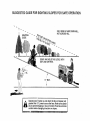
SLOPE OPERATION
Slopes are a major factor "elated to toss-of-control
ann
tipover accident,,
which can result in severe injury or seam.
All slopes require extra caution.
If you cannot back uo me
slope or if you feel uneasy on it. do not mow it.
DO:
Mow up and down slopes, not across.
Remove obstacles such as rocks tree limbs, etc.
Watch for holes, ruts, or bumps.
Uneven terrair could
overturn the machine. Tafl grass can hide obstacles.
Use slow speed. Choose a low gear _a that you will net have
to stop or shift while on the slope.
Follow the manufacturer's
recommenaations
for wheel
weights or counterweights to _mprove s[ao_l_ty
Use extra care with grass catchers or other attacnmems
These can change the stability of the macnme
Keep all movement on the sfc Des stow ann graou_
Do not
make sudden changes in speea or o_receon
Avoid starting or stopping on a slope
f tires lose traction
disengage the blades and oroceea s_ow_ysrratghtdown me
slope.
DO NOT:
Do not turn on slopes unless necessar_, ann men. turn SlOWly
and gradually downhill, if possible
Do not mow near drop-offs, ditches, or emuanKmems
The
mower could suddenly turn over if a wheel is over the edge
of a cliff or ditch, or if an edge caves _r
Do not mow on wet grass Reduced traction could cause
sliding.
Do not try to stabilize the machine b_. 3using your foot on the
ground.
Do not use grass catcher on s_eee sic ses
OBJECTS.
OR DEATH.
Look for this symbol to point out important safety precautions.
It means
CAUTION!!!
BECOMEALERT!!!
YOUR
SAFETY IS iNVOLVED.
d place wire where it cannot contact
plug in order to prevent accidental
staring
when setting
up, transporting,
_
_
--
....
A WARNING
The engine exhaust
from this product contains chemicals
known to the State of California to cause cancer,
birth defects,
or other
reproductive
harm.
=
PRODUCT
CONGRATULATIONS
on your eurcnase of a Sears
Tractor, It has been designed, eng neered and manufactured to give you the best possible dependability and
eerformance.
Should you experience any problem you cannot easily
remedy, please contact your nearest Sears Authorized
Service Center/Department.
We have competent, welltrained technicians and the proper tools to service or repair
this trac[or.
Please read and retain this manual. The instructions wil
enable you to assemble and maintain your tractor propeny.
Always observe the "SAFETY RULES"
MODEL
NUMBER
917.251470
SPECIFiCATiONS
HORSEPOWER:
20.0
GASOLINE CAPACITY
AND TYPE:
5 QUARTS
UNLEADED
OIL TYPE tAPI-SF/SG):
SAE 30 (above 32°F)
SAE 5W-30 (below 32°F/
OIL CAPACITY:
3.0 PINTS
SPARK PLUG:
GAP: .030'
CHAMPION
RJ19LM
VALVE CLEARANCE:
INTAKE:
EXHAUST:
.004" - .006"
.007" - .009"
GROUND SPEED (MPH/:
FORWARD:
ls!
2no
3rd
4th
5th
SERIAL
NUMBER
DATEOFPURCHASE
YOUSHOULDRECORDBOTHSERIALNUMBERAND
DATE OFPURCHASEANDKEEPINASAFEPLACE
FORFUTURE
REFERENCE.
AGREEMENT
A Sears Maintenance
Agreement
uct. Contact your nearest Sears
CUSTOMER
is availab]e on this orodstore for details.
RESPONSIBILITIES
TWO YEAR WARRANTY
TIRE PRESSURE:
FRONT:
REAR:
14PSI
t0 PSt
CHARGING SYSTEM:
3 AMPS BATTERY
5 AMPS HEADLIGHTS
BATTERY
AMP/HR
WIN CCA:
CASE SIZE:
BLADE BOLT TORQUE:
30-35 FT. LBS.
30
240
U1R
WARNING:
This trac[or
is eauiDoea
with an internal
combustion
engine ana should not De usea on or near any
un_mprovea forest-coverea
brush-covered
or grass-covered land unless the engine s exnaus[ system ts eauiDpea
wnn a spark arrestor meeting applicable local or state laws
(if any). If a spark arrester is dsea, t should be malmalned
in effective working order by the operator.
In the state of California
the above is required by law
tSection 4442 of the California
Public Resources
Code
Other states may have similar laws Federal laws apply on
federal lands. A suark arrester for the muffler is available
througn your nearest Sears Authorized
Service Center/
Department
(See REPAIR PARTS section of this manual).
Read and observe the safety rules.
Foliow a regular schedule in maintaining, canng for and
using your tractor.
Follow the instructions under "Customer Resoonsibilities" and "Storage" sections of this owner's manual.
LIMITED
1.1
1.4
2.3
3.5
4.4
5.7
!.7
REVE'RSE:
THEMODELANDSERIALNUMBERSWILLBEFOUND
ON A PLATE UHDER THE SEAT.
MAINTENANCE
REGULAR
ON CRAFTSMAN
RiDiNG
EQUIPMENT
For two {2) years from the aate of ourcnase if this Craftsman Riding Equipment _smalmainea
Jbncated and tuned ue according [o
the instructions in the owner's manual Sears will reea_r or reolace, free of cnarge, any 9arts found to be defective in material or
workmanship.
This Warrant, does not cover:
[ ffo,laaoJe I[ems which become worn during _rmal use sucn as blaae_ spark p=ugs air c;eaners 3elts. e[c
Tire replacemen[ or repair causee oy punctures from outside objoc[e such as naris, morns szumps, or g ass
*
Repairs necessary because of operator abuse, negligence, improper storage or accident or the f_{[lure to maintain the
equipment according to the instructions contained in the owner's manual
Riding equipment used for commercial or rental purposes.
LIMITED 90 DAY WARRANTY
ON BATTERY
For ninety (90) days from date of purchase, if any battery included with this riding equipment proves defective in material or
workmanship and our testing determines the battery will not hold a charge, Sears will replace the battery at no charge.
IN-HOME WARRANTY SERVICE ON YOUR CRAFTSMAN RIDING EQUIPMENT tS AVAILABLE AT NO-CHARGE FOR 30 DAYS
FROM THE DATE OF PURCHASE.
PLEASE CONTACT YOUR NEAREST SERVICE CENTER. AFTER 30 DAYS FROM THE
DATE OF PURCHASE. WARRANTY SERVICE tS AVAILABLE BY TAKING YOUR CRAFTSMAN RIDING EQUIPMENT TO YOUR
NEAREST SEARS SERVICE CENTER. (IN-HOME WARRANTY SERVICE WILL STILL BE AVAILABLE AFTER 30 DAYS FROM
THE DATE OF PURCHASE BUT A STANDARD TRIP CHARGE WILL APPLY.) THIS WARRANTY APPLIES ONLY WHILE THIS
PRODUCT IS fN THE UNITED STATES
This Warranty gives you specific legal rights, and you may also have other nghts which may vary from state to state.
SEARS,
ROEBUCK
AND
CO., D/817 WA. HOFFMAN
3
ESTATES,
IL 60179
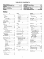
TABLE OF CONTENTS
SAFETY RULES ............................................................
2
PRODUCT SPECIFICATIONS ......................................
3
CUSTOMER RESPONSIBILITIES ..................... 3, 15-19
WARRANTY ..................................................................
3
TABLE OF CONTENTS .................................................
4
INDEX ............................................................................
4
TRACTOR ACCESSORIES ..........................................
5
ASSEMBLY ...............................................................
7-9
OPERATION ..................... _....................................
10-14
MAINTENANCE SCHEDULE .....................................
15
SERVICE AND ADJUSTMENTS ........................... 20-25
STORAGE ...................................................................
26
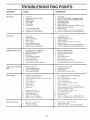
TROUBLESHOOTING ...........................................
27-28
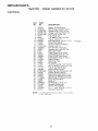
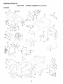
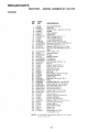
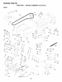
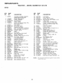
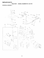
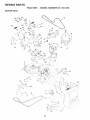
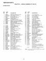
REPAIR PARTS - TRACTOR ................................ 30-47
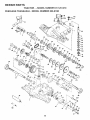
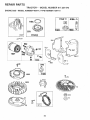
REPAIR PARTS - ENGINE ....................................
48-53
PARTS ORDERING/SERVICE .................. BACK PAGE
iNDEX
A
Accessories ............................................
5
Adjustments:
Brake ...........................................
22
Carburetor .......................
25
'V1L,- g
Front-To-Back ........................
Side-To-Side ..........................
Throttle Control Cabie .................
Air Filter Engine ........................
Air Screen. Engene ............................
Assembly ...........................................
B
Battery:
Charging ......................................
Cleaning .....................................
Starting with Weak Battery ..........
Storage .....................................
Terminals ............................
Belts:
Motion Drive
Removel/Reelacement
...........
Mower Blade Drive
Removal/Replacement
...........
Blade:
Sharpening .................................
Replacement .............................
Brake Adjustment ..............................
C
21
21
24
18
18
7-g
8
17
23
26
"
22
22
16
16
22
Carburetor Adjustment ....................... 25
Controls Tractor ................................
""
Customer Resoonsibilities ............. 15-19
Engine
Air Filter ...............................
18
Air Screen. Engne ............
Battery ..............................
_.oolng Fins, Eeg ne ...............
Engine Oi! .............................
Fuel Filter
18
"
18
"
19
Spark Plugs ..........................
-g
Tractor:
Blades ...............................
16
Lubrication Chart
t5
Maintenance Schedule .......
15
Tire Care
2 16.23
Cutting Height
Mower .....................
E
Electrical
Interlocks and Relays ...........
Schematic ............................
Ninng Diagram ........................
12
Engine
Air Filter .......................................
Air Screen .................................
18
18
Cooling Fins, Engine .................
18
Oil Change
17
Oil Leve ................................. 13.17
O Type ......................................
17
Preearauon .................................
13
Repair Parts ........................... 48-53
Starting ........................................
1,_
Storage .......................................
26
F
Filters:
Air ................................................
18
Fuel .............................................
19
Fuel:
Type .......................................
13
Storage ......................................
26
Fuse .............................................
24
G
Gauge Wheels ..................................... 9
H
Hood Removal/Installation ................. 24
L
Leveling Mower Deck .........................
Lubrication Chart ................................
M
Maintenance Schedule ......................
Mower:
Adjustment =rent-to-Back ..........
Adjustment Side-to-Side ...........
Blade Shareenmg
Blade qeolacemen]
................
21
15
15
2t
21
16
16
Cutting He,gin
17
nsra_la[Eo_
20
Ooera[_on
.............................
13
Remova
.........................
20
Mowing Ties
_a
Muffler ........................
19
Spark Arrester ........................ 3.40
Mulche _ Plate ....................................
9
O
Oil:
Cold Weather Conditions ....... !3 "-"
Engine
..............................
"
3toraue
.............................
26
24
29
30
4
Or_erat=on ......................................
! O-14
Operating Mower ...............................
13
OPtions:
Accessories ...................................
5
Seark Arrester ........................ 3.40
P
Parking Brake ..............................
11-12
Parts Bag .............................................
6
Parts. Reolacement/Repair
........... 30-47
Product Seecfficatiens ........................... 3
R
Repair PaRs .................................
S
30-47
Safety Rules .........................................
2
Seal ......................................................
8
Service and Adjustments .............. 20-25
Brake ........................................
22
Carburetor ...................................
25
Fuse ...........................................
24
Hood Removal/lnstaltation
........ 24
wu,lu, Drive Bell
Removal/Replacement
........... 22
Mower Blade Drive Bell
Removal/Replacement
.......... 22
Mower Adjustment:
Front-to-Back ......................... 21
Side-to-Side ..........................
21
Mower Installation
..................... 20
Mo_ _r Removal .........................
20
Tire Care ............................. 9.16.23
SloPe Guide Sheet ........................
55
Spark Plugs ......................................
19
Specifications .......................................
3
Starting the Engine
.................... 13-14
Steering Wheel ................................
7.23
Stopping the Tractor ........................... 12
t_torage
...................................
26
T
Throttle Control Cable Adjustment ..... 24
Tires
......................................
£ 1623
Trouble Shooting Chart .................. 27-28
Transaxle Rec air Parts ................ 46-47
W
Warram. ..........................................
Wrong Diagram .................................
Wiring Schema1 c
.....................
3
30
29
ACCESSORIES
These accessories
Most Sears stores
and attachments
can order these
AND ATTACHMENTS
were available through most Sears retail outlets and service centers
items for you when you provide the model number of your tractor.
ENGINE
SPARK
when the tractor
was purchased.
MAINTENANCE
PLUG
GAS CAN
ENGINE OIL
FUEL STABILIZER
AIR FILTER
BLADES
BELTS
i
PERFORMANCE
Sears offers a wide variety of attachments that fit your tractor
y'ou. This list was current at the time of Ouellcatlon: nowever
may be made in these attachments, or some may no hr?ger
accessories and attachments
that are available for your
Most of these attacnments do not require additional hitches
attaching and detaching.
Many of these are listed below with brief explanations of how they can help
it may change in future years - more attachments ma, be addeo, changes
be available or fit your model. Cont "* ;,our qearest Sears _
'^" 'he
tractor.
or conversion kits +,hosethat do are indicated and are designed for easy
AERATOR promotes deep root growln for a healthy lawn TaDered
2,5-inch steel SelKeS mourned on 10-inch diameter discs puncture
holes in soft at close intervals to let moisture soak m Steel weight tray
for increased oenetratlon
BUMPER
protects
front end of tractor
from damage
CARTS make hauling easy. Variety of sizes available olus accessones sucn as side oanel kits, tool caday, can cover erotecuve mat ans
dolly.
CORING AERATOR
takes smelt elugs out of soil to a_low moisture
and nutrier_s to reaen grass roots. 36-inch swath. 24 hardened stee_
conng tips
150 lb. capacity weight tray
DISC HARROW has 2 gangs of 4 steel e_ades teat angle from t0 to
20 degrees 40 _nches wide. Can hook 2 umts n tandem.
[Reauwes
sleeve
niter
DOZER BLADE removes snow: grades air sand and gravel 48
nches wtde 17 inches hig h clears 44-inch paT wnen angled. Master
lift control lever for ooeraror ease. Spring trip for snow removal on
uneven pavement:
built-in float for blade to follow ground contour.
Reversible
reelaceabte scraeer bar. (Usewtthtirechamsandwheel
weights and/or rear drawbar weight.)
EASY OIL DRAIN
VALVE
makes
oil changes
GANG HITCH
lets you to',_ 2 or 3 eulFben_na
once
SUch as sweeDers,
dethatchers
aerators
deck to reduce
attacnmems
al
use with
(not for
roliers ears or otner neavy attachments
MULCH RAKE!DETHATCHER
oosens so and flies tna_cn and
matted _eaves to _awn sudace for easy p_cKup Twenty spring tine
teetn Useful to predate bare areas for seeding
Available for front dr
rear mouncng.
HIGH PERFORMANCE
REEL-ACTION
SPRING
TINE DETHATCH ER covers 36dnch wide cam and tosses rnatcn into
large hopeer
Mounts behind tractor.
PLOW turns soil 6 ncnes aeee. cuts lO-inch furrow.
ment controls depth, 3-position yoKe sets w_dtn, tlea_,
for straight furrowing
tReauRes s_eeve mtcn,
Crank adjuststeel lanuslae
RAMP TOPS AND FEET _et you oaa and unload tractor
DICKUD[tUCK use with 2 x 8 or 2 x 10 lumber.
SLEEVE HITCH for use with master
uncouples
from a
REAR GRADER BLADE is 42 Inches wide and oeerated from drwer's
seat, Reversible steel blade can be angled at 30 degrees for grading.
Reverses for pusntng snow backwards
rRegu.'es sleeve h_tch
ROLLERforsmootherlawnsurfac_
36-mchw=de
18qnchdEamete[
water-t_gm drum no_as JD tO 390 Ibs _f weight
Rounded edges
Drevent harm to turt
Adjustable scrader automatLcalij
cleans arum.
lift system.
Singte ptn couples/
SNOWTHROWER
has 42-inch swath
Drum-type
auger handles
powdery and wet/heav,'snow.
Mounts eastly with simple pin arrangemeT.
Discharge cnute adjusts from tractor seat. 6-inch diameter
SCOUt atscnarges
snow 10 to 50 feet
dft controlled at tractor seat
use wnn cnams and wheel weEghts and/or rear drawbar weigm
SPRAYERS
use 12-volt DC electric motor that connects to the tractor
ca[tery or other 12-volt source
nc_udes dooms for automatic
spraying aria nard held wand for sect seraymg. Wand has ac.ustable
spray ¢ _ttern Cor aDDly_ng nerelclaes
lnsectlclaes,
fungicides and
ueuid fertilizers.
SPREADER/SEEDERS
make seeding, fertilizing
and weed killing
easy. Broadcast spreaders are also useful for granular de-icers and
sand.
SWEEPERS
easier, faster.
FRONT NOSE ROLLER canters in front of mower
chances of "scalDing" on uneven rerra=n.
SLEEVE
CULTIVATOR
_ 43 inches NiCe Prepares
ground for
seeding, neles weed control. Steel frame holds 5 adjus[aele sweess
Adjusts vertically, honzontall,
(Reouires sleeve h_tch
Optional
accessory:
steel furrow opener Ior w}aer openings
for potatoes
corn and other deee-seeaea
croes
let you collect
grass clippings
and leaves,
TILLER has 8 hp engme [o prepare seed Beds. culrwate, and compost
garaen resJaue. Chain-drive transmission.
Six 11-inch diameter one
3_eee heat-treated steel tines, Tills 30aneh BUtt" fReau_res steeve
mtclq Or use 5 hE tow-behind TILLER with 36-inch swath to orecare
seed eeas cumvate and compost garden residue
Tiller has _ts own
:)uittdn lift and deem control system and does NOT require a steeve
- ton =its any _wn, yard or garden tractor
Simply nOOK ue tO the
_ractor nrawear end go Optiona_ accessories
for 5 hc t{_ter conveR
unit
for dethatohm
], aerating, niiHng
without
tools
TiRE CHAINS are heavy duty; closely spaced
give smoom ride outstanumg tracsor
extra-large
cress _nK_
TRACTOR CAB has heavy duty wny_ fabnc over tubular steel frame
ABS elastic to[): c_ear o_ast_c wlnasn_e_J offers 360 degree ws_ou
rllngea
metat doors WIT catce
ReeDs operator warm and dry
Remove wny_ s_ae_ and w_nosn_elas [or use as sun oroteczor
summer.
Optional
accessories
include:
tlnteditem#erea
sofia
safety g_ass t_,masn_e_d wttn nana oderatea
N_eer 12-volt ameer
caution light for mounting on CaD rOD
VACS for oowerfut collection of near, grass c_{pp_ngs and ea yes
Oetiona l wand attachment
to 91OKgC dec rIs _nnard-to-reacn
DidOeS
VAC/CHIPPER
mcluaes a cr nner-snredaer.
WEIGHT BRACKET
for drawbar for snow removal aeol_cat_ons Can
De mounted on front of tractor for DIOW_R] aeDIICaSons
dses It 55
[D. wel gel
WHEEL WEIGHTS fol rear whee :_[)rowae rleeae_ traction for :_now
remowu
or Oozing
nervy
m_}[erl;lis
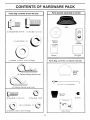
CONTENTS
Parts Bag contents
shown
OF HARDWARE
PACK
Parts packed separately
full size
in carton
Seat
f
(1JShoulder'Bolt
5/16-18
1_ Lock
Washer
_1 HexBolt
1'2-13xi
)
Steering
Wheel
1/2
Video
Cassette
/
Manual
{llWasher
17/32xl-3/16x12Gauge
Parts
Parts Bag
bag contents
not shown
full size
,%
Steering
Wheel
Insert
(3) Retainer Spnngs (doub]e loop)
2 Frollt Lnk Assemblies
(4) Retainer Sonngs tsmg e tooot
Steering
Sleeve
_2) Hex Bolts 1 4-20 x 3/4
2} Hex Nuts
2 Lock Washers
(2) Washers
9/32 x 5/8 x 16 Gauge
i/z[
!2) Keys
t/4-20
_,_
Slope Sheet
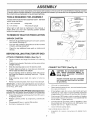
LY
Your new tractor has been assembled at the factory with exception of those Darts left unassembled for shipping purposes.
To ensure safe and proper operation of your tractor all 0arts and hardware you assemble must be tightened securely, Use
the correct tools as necessary to insure proper tightness.
TOOLS REQUIRED
FOR ASSEMBLY
(2) 7/16
wrencnes
STEER,NG
WHEELINSERT
A socket wrench set will make assembly eas_er. Standard
wrench sizes are listed,
r
_._.._LOCKNUT
Utility knife
(1) 1/2 wrencn
LARGE
/"AShZR
Tire Ùressuregauge
When rlgnl or left nana _s memlonea * this manua_ [
means when you are in the operating Position (seated
behind me steenng wneeu.
f
FLAT
STEERING
L
-_-_-_'IWHEE
TO REMOVE TRACTOR FROM CARTON
UNPACK
CARTON
Remove all accessible 1Dose oars ana OaRScanons
from carton (See page 6).
Cut. from top to bottom, along lines on all four corners
of carton, and lay panels flat.
Check for any additional
remove.
_oose pars or cartons and
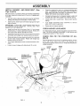
BEFORE ROLLING TRACTOR OFF SKID
ATTACH
STEERING
WHEEL
(See
Fig.
l
1)
Remove Iocknut ana large fiat washer from steenng
shaft.
FIG. 1
Position front wheels of the tractor so they are polm_ng
straight forward.
Slide the steering sleeve over the steering shaft
CONNECT
Position steenng wheel so cross bars are horizonta
deft to right) and slide onto adapter.
wheeI
Remove orotectlve
nsen
DlaStiC
mo center of steering
Positive terminal must be connected
first to prevent sparking from accidental grounding,
from tractor hood and gem
IMPORTANT:
CHECK FOR AND REMOVE ANY STAPLES
N SKID THAT MAY PUNCTURE TIRES WHERE TRACTOR
S TO ROLL OFF 3KtD.
Lift hood _o ra_sea DOSe[on
ODen terminal access doors, remove termlna
[ive
TO RO LLTRACTOR
section for location
(See Fig. 2)
CAUTION: Do not short battery terminals. Before connecting
battery, remove metal bracelets,
wristwatch
bends, rings, etc.
Secure steering wheel to steering shaft with Iocknut
and large flat washer oreviously removeD. Tighten
securely.
SnaD steering
wheel.
BATTERY
OFF SKID {See Operation
and function
of controls)
CaDS
and
3rotec-
DiscarD,
If this battery sour into service after monm and year
indicated on labe labe ecated between terminals
charge battery for minimum of one hour at 6-10 amos.
Press ft Iever 31unger and raise attachment lift lever to
its hignest oosmor
First connect RED Darter, :aeie to 3ositive (+) battery
term qat with hex bolt. flat washer, lock washer and Rex
nut as ShOWn Tighten securely.
Release parKing DraKe by aepress_ng clutch/brake
pedal.
Place gearshift lever in neutra fN/ DOShoe.
Rc tractor backwards off skid.
Connect BLACK grounding caole to negatwe (-) batrer, terminal With rema_nm _ nex Do flat washer loc_
washer ana nex nu_. Tighten securely.
Close terminal access doors
use termlna access doors for:
nsoeciton
ware).
7
fol secure connecuons
(to tlgnteF narD
ASSEMBLY
Inspection for corrosion.
INSTALL
Testing battery.
Adjust seat before tightening adjustment bolt.
Jumping (if required),
Remove cardboard packing on seat pan.
Place seat on seat oan ana assemble shoulder bolt,
Periodic charging,
HEX NUT
SEAT (See Fig. 3)
LOCK
WASHER
DISCARD TERMINAL
PROTECTIVE CAPS
Assemble aQjustment bolt, lock washer and flat washer
loosely. Do not tighten.
FLAT
WASHER
/
Tighten shoulder bolt secure y.
Lowe. ,_eat q[o operatl% Jos_',on and sit on seat.
HEX
BOLT
Slide seat until a comfortable position is reached which
allows you to Dress clutch/brake pedal all the way
aown.
TERMINAL
ACCESS
DOOR
Get off seat without moving ts adjusted oosition.
Raise seat and hghten adjustment bolt securely.
POSITIVE
(RED)
CABLE
SEAT
(BLACK)
CABLE
SEATPAN
_
SHOULDER
BOLT
\
FLAT WASHER
/
...
ADJUSTMENT
BOLT
bLOCK
WASHER
FIG. 3
CHECK
TIRE PRESSURE
The tires on your tractor were overinflated
shipping eureoses Correct tire oressure
best cutting Derformance.
Reduce tire 3ressure [o PS snown
SPECIFICATIONS" or page 3 of this
CHECK
BRAKE
at the factory for
s mportant for
in "PRODUCT
manual
SYSTEM
Afte- y 3u learn how to operate vour tractor
check to see
_na[ the DraKe s properly
:_dJJs_ea, See 'q-O ADJUST
BRAKE"
ntne
Service anu Adjustments
secuon of m_s
manua
8
ASSEMBLY
INSTALL MOWER
Figs. 4 and 5)
AND
DRIVE
BELT
Place the suspension arms on outward pointing BeCK
pins. If necessary, rock and raise front of mower to
align deck pins with the holes in suspension arms.
Retain with double loop retainer springs.
(See
Be sure tractor is on leve_ surface and mower suspension
arms are ralsea with attachment lift control, Engage parKmg DraKe.
Connect anti-sway bar to chassis bracket under left
footrest and retain with double loop retainer spring.
Install clutch rod in clutch lever. Secure with retainer
spnng.
Cut and remove ties secunng anti-sway bar and belts,
Swing anti-sway bar to left side of mower deck,
Slide mower under tractor with discharge guara [o r gm
side of tractor.
Turn nelgm aajustment knob clockwise
slack from mower susoenslor
IMPORTANT: CHECK BELT FOR PROPER ROUTING IN
ALL MOWER PULLEY GROOVES INSTALL BELT INTO
ENGINE =ULLEY GROOVE.
Install one front link in top hole of the L.H. front mower
:)racket and C.R. from suspension
DracKeL
Reta 3 WIl[n
[we single loop retainer springs as snown.
Install second front link in R.H. front susoension bracket
and retain with single _OOOreta=ner spring as snown.
Raise deck to highest eosition.
CHECK
MOWER
LEVELNESS
For best cuttin_ resu_s, mower snoula De properly eveneD.
See "TO LEVEL MOWER HOUSING" in the Service and
Adjustments section of this manual.
CHECK
BELTS
Slide right side of mower back and install link in top hole
of R.H. front mower bracket. Retain with s_ngle loop
retainer spring as snown.
FOR
PRC2ER
POSITION
StODS.
Lower mower linKage with attachment lift control
CLUTCH
LEVER
ROD
FRONT
LINKS
RETAINE_
SPRING
SUSPENSION
ARMS
DOUBLE LOOP
RETAINER SPRING
/.
LOOP
RETAINER SPalNG
(Outward pointing
deck pins)
.-
/
/
CHASSIS
BRA(J;_c
\
\
\
OF ALL
See the figures that are shown for replacing motion, mower
arwe. ana mower blade anve belts in the Service and
Adjustments section of this manual. Verify that the belts are
"outed correct y.
Turn heigm aajustment KnOB coumerclocKw_se until it
DOUBLE
_o remove
/
FRONT
SUSPENSION
BRACKETS
/
/
/
/
ENGINE
\
,
_, _
SINGLE
LOOP RETAINER
SPRINGS
_"_"-._
/
FRONT
MOWER
BRACKET
/
ANTI-SWAY
BAR
/
IDLER
PULLEY
DISCHARGE
_GUARD
FIG. 4
9
ASSEMBLY
J" CHECKLIS T
BEFORE YOU OPERATE AND ENJOY YOUR NEW
TRACTOR. WE WISH TO ASSURE THAT YOU RECEIVE
THEBESTPERFORMANCEAND
SATISFACTION FROM
THIS QUALITY PRODUCT
PLEASE REVIEW THE FOLLOWING
CHECKLIST:
¢"
All assembly _nstruct_ons have been completed.
,/
No remain ng loose 3arts in carton
/
Battery ts properly prepared and chargea.
hour at 6 amDs).
{Minimum
,z
Seat is adjusted comfortably
v"
All tires are properly inflated. {For shipping purposes.
the tires were overinflated at the factory h
and hghtened securely.
,/
Be sure mower deck is properly leveled slde-to-slae/
front-to-rear for best cutting results, tTires must De
properly inflated for leveling).
,/
Checkmoweranaanvebelts.
Besuretheyarerouteu
properly around pulleys and inside all belt keepers.
,/
Check wiring. See that all connections are still secure
and wires are properly clampea.
WHILE LEARNING HOW TO USE YOUR TRACTOR. PAY
EXTRA ATTENTION TO THE FOLLOWING IMPORTANT
ITEMS:
,/
Engine oil is at oroper teve
,/
Fuel tank is filled with fresh clean, regular unleaded
gasoline.
,/
Become familiar w th all controls - their location ana
function. C _erate them before you start the engine.
,/
Be sure brake system _sin safe operating condition.
10
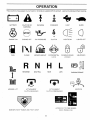
OPERATION
These symbols may appear on your tractor or in literature supplied with the oroduct. Learn and understand their meaning.
l::3A
,
t
BATTERY
CAUTION OR
WARNING
REVERSE
FORWARD
FAST
SLOW
ENGINE ON
ENGINE OFF
OIL PRESSURE
CLUTCH
LIGHTS ON
LIGHTS OFF
FUEL
CHOKE
MOWER HE'IGHT
DIFFERENTIAL
LOCK
PARKING BRAKE
LOCKED
UNLOCKED
L
REVERSE
MOWER LIFT
NEUTRAL
ATTACHMENT
CLUTCH ENGAGED
HIGH
LOW
PARKING
ATTACHMENT
CLUTCH DISENGAGED
4YDROSTATIC
DANGER. KEEP HANDS AND FEET AWAY
IGNITION
FREE WHEEL
(Hyaro Models on y)
11
BRAKE
m
OPERATION
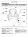
KNOW YOUR TRACTOR
READ THIS OWNER'S
MANUAL
AND SAFETY
RULES
BEFORE
OPERATING
YOUR TRACTOR
Compare the illustrations with yDu r tractor to familiarize yourself with the locations Df various controls and adjustments.
this manual for future reference.
AMMETER
Save
IGNITION
SWITCH
THROTTLE
THROTI'LE
CONTROL
CONTROL_,
LIGHT
SWITCH
CLUTCH/
BRAKE
PEDAL
ATTACHMENT
CLUTCH LEVER
PARKING
DRAKE
HEIGHT
KNOB
GEARSHIFT
LEVER
FiG, 5
Our (ractors conform to the safet, standards of _ne American National S_andards Inst![ute.
ATTACHMENT
mower blades
trac[or.
UGHT SWITCH:
THROTTLE
GEAR SHIFT LEVER • Selects the soeea aria alrecuon of
the tractor.
CLUTCH LEVER: usea [o eng_ge the
or other attachments moumea to your
ATTACHMENT LiFT LEVER: Used to raise and lower the
mower deck or other attachments mounted to your trac[or.
Turns the headlights on aria off.
CONTROL:
LIFT LEVER PLUNGER Used to reIease attachment lift
ever wnen changing [s position.
useu [o control engine soeee.
CLUTCH/BRAKE PEDAL: Used fordeclutchlng ana oraK.
ing the tractor and starhng rne eng=ne
PARKING BRAKE: LOCKS clutch/brake 9eaa mo me
DraKe position.
CHOKECONTROL
IGNIT!ON SWITCH:
eng ne
Used for starting and stopping tne
HEIGHT ADJUSTMENT
cutting height.
- Usea when starting a cold engtne.
AMMETER:
(-)
12
KNOB: usect [o aajust tne mower
Indicates hattery charging (4-) or discharging
PERATION
_u_
_
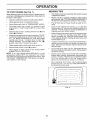
The operation of any tractor can result in foreign objects thrown into_
resultinsevereeyedamage.
Always wear safety glasses or eye shields while-operating your
tractor or performing any adjustments or repairs. We recommend a wide vision safe_ mask
_andard
safety glass?.
HOW TO USE YOUR TRACTOR
I
TO SET
PARKING
(See Fig. 6)
BRAKE
pedal into full "BRAKE
p_edab(_ve,
beforeleavingthe o_ , J,_,'_ position; to empty
_r,
Your tractor is equipced with an operator presence sensing
switcn. When engine is running, any a[[emp[ cy the
operator to leave the seat without first setting the parking
crake wilt shut off the engine.
Depress clutch/brake
and hold.
_
_
etc.
TO USE
THROTTLE
....
(See Fig. 6)
CONTROL
Always operate engine ot full throttle.
position
Operating engine at tess than full throttle reduces the
battery charging rate.
Place parking brake lever in "ENGAGED" position and
release pressure from clutch/brake pedal. Pedal should
"emaln in "BRAKE" uosition. Make sure parking crake
will hold tractor secure.
Full throttle offers the best bagging and mower performance.
TO USE CHOKE
ATTACHMENT CLUTCH LEVER
"ENGAGED"
POSITION
THROTTLE/CHOKE
CONTROL
To engage choke control, pu! knob out. Slowly push
knob in to disengage.
"DISENGAGED"
/
/
'BRAKE"
POSITION
./
POSITION
PARKING BRAKE
"ENGAGED"
POSITION
/"
(See Fig. 6)
Use choke control whenever you are starting a co_e engine.
Do not use to start a warm engine.
/
"_
CONTROL
TO MOVE FORWARD
(See Fig. 6)
GEARSHIFT
LEVER
AND BACKWARD
The direction and soeed of movement
gearshift _ever.
_scontrolled by me
Start tractor wnth clutch/brake peoal depressed and
gearshift lever in neutral (N) position.
•
"DISENGAGED"
POSITION
CLUTCH/BRAKE
PEDAL "DRIVE"
POSITION
HEIGHT ADJUSTMENT
KNOB
TO ADJUST MOWER
(See Fig. 6)
(See Fig. 6)
MOWER BLADES Move attachment clutch lever to "DISENGAGED" position.
GROUND DRIVE •
Depress clutch/brake pedal into futI "BRAKE" position.
,
Move gearshift lever to neutral (N) position.
ENGINE -
CUTTING
HEIGHT
The cutting height is controlled by turning the height adjustment knob in desired direction.
Turn knob clockwise (/'-_)
Turn knob counterclockwise
height.
to raise cutting height.
(_)
to lower cutting
The cutting height range is approximately 1-!/2" to 4". The
heights are measured from the ground to the blade tip with
the engine not running. These heights are approximate
and may vary depending upon soil conditions, height of
grass and types of grass being mowed.
.
Move throttle control to slow ("gl,) position.
NOTE: Failure to move throttle control to slow (=gk.)
position and allowing engine to idle before stopping may
cause engine to "backfire".
Turn ignition key to "OFF" position and remove key.
Always remove key when leaving tractor to prevent
unauthorized use.
Never use choke to stop engine.
NOTE: Under certain conditions when tractor is standing
idle with the engine running, hot engine exhaust gases may
cause "browning" of grass. To eliminate this possibility,
always stop engine when stopping tractor on grass areas.
position.
Slowly release clutc, ,,,J__e pedal to start movement.
IMPORTANT: BRING TRACTOR TO A COMPLETE STOP
BEFORE SHIFTING OR CHANGING GEARS. FAILURE
TO DO SO WILL SHORTEN THE USEFUL LIFE OF YOUR
TRANSAXLE.
FIG.6
STOPPING
Move gearshift lever to desired
The average lawn should be cut to approximately 2-1/2
inches during the cool season and to over 3 inches
'during hot months. For healthier and better looking
lawns, mow often and after moderate growth.
For best cutting performance, grass over 6 inches in
height should be mowed twice. Make the first cut
relatively high; the second to desired heighL
13
I
OPERATION
TO OPERATE
MOWER
(See Fig. 7)
Move gearshift lever to 1st gear. Be sure you have
allowed room for tractor to roll slightly as you restart
movement,
Your tractor is equipped with an operator presence sensing switch, Any attempt by the operator to leave the seat
with the engine running and the attachment clutch engaged
will shut off the engine.
To restart movement, slowly release parking brake anc
clutch/brake Dead
Make all turns siow_y.
Select desired height of cut.
Lower mower with attachment lift control.
Start mower btades ......
drag attachment
TO TRANSPORT
clutch
Raise attachment
ment lift control.
centre
TO STOP MOWER BLADES - disengage attachment
clutch control.
ift to nighest Dos_tIon with attach-
When pushing or towing your tractor. De sure gearshift
lever is _n neutral NI oos tlon.
CAUTmON: Do not operate the mower
Do not Bush or tow tractor at more than five (5) MPH.
without either the entire grass catcher,
on mower., so equipped, or the dis-
NOTE: To protect need from damage when transporting
your tractor on atruckor a trailer. Be sure hood is closed and
secured to tractor. Use an appropriate means of tying hood
[o tractor trope, core etc.,
ATTACHMENT CLUTCH
LEVER DISENGAGED
"ENGAGED"
POSITION
POSITION
_
/
BEFORE
ATTACHMENT
J
CHECK
ENGINE
THE ENGINE
OiL LEVEL
(See Fig. 12)
HIGH POSITION
The engine =nyour tractor has been shipped, from the
factory, already filled with summer weight oil.
LIFT LEVER
Check engine oil with tractor on level ground.
Unthread and remove oil fill cap/ulpstick: wtpe oil oft.
Reinsert the diestick into the tube and rest oil fill cap on
thetube, Donotthreadthecauontothetube,
Remove
ano read oil love
I necessary, add oil until "FULL"
mark on dipstick s reacneu. Do not overfill.
LOW
"_
STARTING
POSITION
For cola weather oeerat=on you should change oil for
easier starting _See "OIL VISCOSITY CHART" in the
Customer Resoonsibilities section of this manual).
To change eng "_eo=I.see the Customer Responsibilities section in this manual.
ADD GASOLINE
Fill fuel tank. Use fresh, clean, regular unleaded
gasoline with a minimum of 87 octane. (Use of leaded
gasoline will increase carbon and lead oxide deuosits
anc reduce vawe if_. Do not mix oil with gasoline.
Purchase rue - J Jant_t_esthat can be used within 3:;
days to assure fue fresnness.
IMPORTANT: WHEN OPERATING ",,ITEMPERATURES
BELOW32"F(0°C/
JSEFRESH CLEANW NTERGRADE
3ASOLINE TO HELP INSURE GOOD COLD WEATHER
STARTING
WARNING:
Exaenence qatcates that alcohol blended
fuels coiled gasono_ or using etnanc or methane) can
attract moisture which leads to separation and formation of
acids during storage. Acidic gas can damage the fuel
system of an eng De while tn storage. To avoid engine
oroblems, the fuel system should be emptied before storage of 30 days or onger. Drain the gas tank. start the
eng ne and iet it run utah the rue lines and carburetor are
empty. Use fresh fuel next season. See Storage Instrucuons for auud_ona nformation.
Never use engine or
carburetor cleaner Droducts In the fuel tank or oermanent
oamage may occur.
DISCHARGE
GUARD
FIG. 7
TO OPERATE
ON HILLS
CAUTION:
Do not drive up or down
hills with slopes greater than 15 ° and
do not drive across any slope.
Choose the slowest seeed before starting up or down
qiIIs
Avoid stopp_ng or changing speed on n_Hs
f slowing s necessary,
slower DOSltlon
move [nro[ue control ever to
If stopping Is absolutely necessary, pusn clutcn/oraKe
3edal quickly to DraKe POSItIon an(] engage parking
DraKe,
14
OPERATION
TO START
ENGINE
MOWING
(See Fig. 7)
Tire chains cannot be used when the mower housing
is attached to tractor.
When starting engine for the first time or if engine has run
out of fuel. it will take extra cranking time to move fuel from
the tank to the engine
Deoress clutch/brake
Mower should be properly leveled for best mowing
performance. See "TO LEVEL MOWER HOUSING" in
the Service and Adjustments section of this manual.
pedal and sel parking Drake,
Place gearshift lever n neutral IN) positior
Move attachment clutch to "DISENGAGED"
TIPS
The left hand side of mower should be used for trimming.
Drive so that clippings are dischar_._a OhLOthe area
that has been cut. Have the cut area to the right of the
machine. This wil result in a more even distribution of
clippings and more uniform cutting.
oosition.
Pull choke contro_ out to choke ,,_ ) position for cold
engine start. For warm engine star ao not use ChOKe
control.
Move throttle control to midway between fast (.t_) ana
slow [ _ ) Positions,
When mowing large areas, start by turning to the right
so that c!in,3ings will discnarge away from shrubs.
fences, driveways, etc. After one or two rounds, mow
n the opposite direction making left hand turns unt
finished (See Fig. 8/,
qsert Key _nzoLgnitionand turn key c ockwise to"START"
position and release Key as soon as engine starts. Do
not run starter continuously for more than fifteen
seconas per minute. If engine aoes no1 star[ after
severa attempts, move throttle control to fast (,_)
3osition. wait a few munutes ana try again
if grass _sextremely tal!. _tshould be mowed twice to
reduce load and possible fire hazard from dried clippings. Make first cut relatively nrgh: the second to the
desired height,
When engine starts, slowly push choke control in.
Move throttle control to fast ,_) position.
Do not mow grass when it s wet. Wet grass will Plug
mower and leave undesirable clumps. Allow grass to
ary before mowing.
Allow eng ne to warm UD for a few minutes before
engaging drive or attachments.
NOTE: if at a high altitude [auove 3000 feet 3r in cold
temperatures [below 32°F), [ne carburetor rue m_xture
may need to be adjusted for best engine performance. See
"TO ADJUST CARBURETOR" in the Service ana Adjustments section of this manual.
Alwa/s operate engEne at full throttle when mowing to
assu_'e better mowing performance and proper discnarge of material Regulate ground speed by selecting a tow enougn gear to gwe the mower cutting
oerformance as we as me qaaHry of cut desired.
When operating aTmcnmems, select a arouna sueea
that will su_t the uJrann and gwe best performance of
the attachment Demg usea.
/
f
.-.,
FiG. 8
15
CUSTOMER
MAINTENANCE
RESPONSIBILITIES
SCHEDULE
FILL IN DATES
AS YOU COMPLETE
REGULARSERVICE
SERVICE
Check Brake Operation
_#'
J
Check Tire Pressure
_#4
v'
Check for LooseFasteners
Sharpen/ReplaceMower Bladcs
Lubrication Chart
v'
v'
Check Battery Level/Recharge
Clean Battery and Terminals
v'
v'
Check Transaxle Cooling
m
Adjust Blade Belt(s)Tension
Motion Drive Belt(s) Tension
Adjust
m
Check Engine Oit Level
Change
Engine
mmmm
'V'
Oil
V'2
Clean Air Filter
Clean Air Screen
Inspect
Arrester
Muffler/Spark
Replace
Oil F{Iter(If
equipped)
Clean Engine CoolingFins
V'2
Replace Spark Plug
v'Jl
Replace
Air Filter Paper
Cartridge
Replace Fuel Filter
* Change
2 - Se_ice
mor_
oflen
more
oftel3 when
3 - tf e(]u_p#ed
4 - RePlace
GENERAL
when
with oil rifler,
blades
more
c 3erat_ng
u_oer
oDer_ln{J
in {31r_ or Gusl_ con(_[ions
cnange
often
when
otl eve_
mowing
a rte_w
ioa{3 or En rf_(jt_ amDlel_[
5 - If eaulapea wltn aa_ustaDle system.
6 - Not reauired if eaufoDed with maintenance-free
battery
7 - Tigllten Iront axle Divot bolt to 35 fl.qbs, maximum
Co not overt _n[ert.
[erPPeta[urBs,
50 hours.
in SaRQy SO
LUBRICATION
RECOMMENDATIONS
The warranty on tn_s tractor does not cover items that have
been subjected to ooerator abuse or negligence.
To
receive full value from the warranty, operator must maintain
tractor as instructed _nthis mar-ua=.
(_) SPINDLE
ZERK---_
CHART
_
]-_
SPINDLE ZERK (:_
® FRONT
================================
RONT
WBEE
®
Some adjustments Nm qeeo _o be maae periodically to
properly maintain /our tractor
BEARING
ZERK
_-'_. "
_.
[ .-_
BEARING
All ad Jstments q the Service and Ad.ustments section of
tnts manuat snoulo De cnecKea at least once each season.
ZERK
®
Once a year you should replace the spark plug, clean
or reotace a_r filter and check blades ana Dells for
wear. A new sParK p_ug ana clear atr filter assure
proper air4uel mixture and help your engine run better
aria
BEFORE
(_)ATTAC
CLUTCH
PtVOTtS!
astlonger.
EACH
®
USE
PIVOTS
Check englne oil level.
Check brake operauon
(_) SAE 30 OR 10W30 MOTOR OIL
Check tire pressure.
Check for loose fasteners
(_) GENERAL
(_
PURPOSE GREASE
REFER TO CUSTOMER
RESPONSIBILITIES
"ENGINE"
SECTION
IMPORTANT:
DO NOT OIL OR GREASE THE _IVOT PC NTS
NHtCH HAVE SPECIAL NYLON BEARINGS
VISCOUS
LUBR
CANTS WiLL ATTRACT DUST AND 31RT THAT WILL SHORTEN
THE LIFE OF THE SELF-LUBRICATING
BEARINGS
_ YOU
FEEL THEY MUST BE LUBRICATED
USE ONLY A DRY. POW1_
DERED
GR_,PHITE
TYPF
LUBRICANT
SPARINGLY
CUSTOMER
RESPONSIBILITIES
TRACTOR
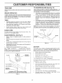
TO SHARPEN
Always observe safety rules when performing any maintenance.
Care should be Taken to Keep the blade balanced.
An
unbalanced blade will cause excessive vibration and eventua! damage to mower and engine.
BRAKE
OPERATION
To check blade balance, you will need a 5/8" diameter
steel bolt, pin, or a cone balancer, (When using a cone
balancer follow me instructions suppl_ed w_th balancen.
Slide blade on to an unthreaded 3oilion of the steel bolt
or D_naria no d the bolt or pin parallel with the grouna
If blade is Dalancea. it should remain _n a horizontal
nosition. If e_tner end of the blade moves downwara
snarpen tee neavy end unti Tne Blade is balaneeu.
TIRES
Maintain proper air pressure in al t_res See "PRODUCT SPECIFICATIONS"
on page 3 of this manuau.
Keep tires free of gasoline, oil. or insect control chemicals which can harm rubber.
NOTE: Do not use a nail for balancing blade. The lobes of
the center hole may appear to be centered, but are net.
Avoid stumps, stones, aeep ruts. shard oBJeCTSaria
other hazards that may cause tire damage.
CENTER
BLADE CARE
For best results mower blades must be kent snarp
oJace bent or damageu Dlaaes
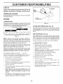
REMOVAL
(See Fig. 10)
The blade can be sharpened with a file or on a grinding
wheel, Do not attempt to sharpen while on the mower.
If tractor requires more than s_x _3) feet stopping distance
at high speed in highest gear. then brake must be adjus[eo.
See "TO ADJUST BRAKE" n The Service and AdjusT_nents section of this manual,.
BLADE
BLADE
HOLE
Re-
(See Fig. 9)
BLADE
5/8" BOLT
OR PIN _
Raise mower To highest position to allow access To
blades.
/
/-
Remove hex bolt. _ockwasher ant flat washer securing
blade.
nstall new or resnarpenea Diane w_[n (ramng eage up
towams aeoK as shown
FIG. 10
Reassemble hex bolt. lock washer and flat washer in
exact order as shown.
BATTERY
Tighten bolt securely [30-35 Ft. Lbs. Torque).
IM.'?qTANT:
BLADE BCL- '" GRADE 8 HEATTREATED.
Your tractor has a battery charging system which is sufficient for normal use. However. periodic charging of the
battery with an automotwe charger will extend its life.
NOTE: Wede net recommend sharpening blade- but ifyou
do. be sure the blade is balanced.
Keep battery and terminals clean.
Keep Battery oo_ts t_gm
Keep smal ent noles open
BLADE
\
Recharge at 6-10 amperes for " hour.
TO CLEAN BATTERY AND TERMINALS
Corrosion ana air on tee pottery arc] terminals can cause
me Battery to "leak" Bower.
TRAILING
FLAT WASHER
._
LOCK WASHER
,.....
Remove terminal ] Jaro.
EDGE
/
Disconnect BLACK batter, ;aBle first Teen RED Dab
tory cap_e ann remove battery from tractor
Rinse the battery w_TnGlare water and dry
Clean terminals and Do[Tory cable ends with wire brush
until Dngnt.
HEX BOLT
(GRADE 8)*
Coat terminals with grease or oetroleum jel y.
*A GRADE 8 HEAT TREATED BOLT CAN BE
IDENTIFIED BY SIX LINES ON THE BOLT HEAD.
Reinstall battery (See "CONNECT
Assembly section of this manual).
FIG. 9
17
BATTERY"
in the
CUSTO
RESPONSIBiLiTIES
V-BELTS
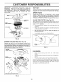
AIR SCREEN
Check V-belts for deterioration and wear after 100 hours of
operatior ano replace t necessary. The belts are not
adjustable. Replace belts if they begin to slip from wear.
TRANSAXLE
OIL
DRAIN
PLUG
COOLING
Keep transaxle free from build-up of dirt and cnaff whicP
can restnct cooling.
OiL FILL
CAP/DIPSTSICK
ENGINE
j_J"
"
LUBRiCATiON
Only use high quality detergent oil rated with APISB "vice
classification S P o r SG. Select the oil's SAE viscosity g rade
according to your expectea operatmg temperature.
SAE VISCOSITY
*2g
-3(
0
3C
-20 r_
TEMPERATURE
-10"
32°
FIG. 12
CLEAN
AiR SCREEN
[See Fig. 12)
Air screen must De KeDt free of dirt and chaff to prevent
engine damage from overheating. Clean w_tn a wire brush
or compressed air to remove u_rt and stubborn dried gum
fibers.
GRADES
40
0°
RANGE ANTICIPATED
60 _
8(
10_
BEFORE
20 °
30 °
AiR FILTER
NEXT OIL CHANGE
Your engine will not run 3ropeny using a dirty air filter.
Clean the foam ore-cleaner after every 25 hours ot operation or every seasor
Service pacer cartridge every 100
qours of coeration or every season, whichever occurs first.
FiG. 11
NOTE: Almough multl-wscosity otis _5W30. 10W3O etc.,
improve staring in cold weather, these multi-viscosity oils
Nil! result in increased oit consume[it n when used above
32°F, Check your engine o evel more frequently to avoid
possIDte engine damage from running low on oil.
Service air cleaner more often unaer aus_y conditions
Remove
_na
cover
Slide foam pre-cleaner off cartridge.
Wash it in liauid detergent and water.
Squeeze it dry n a clean cio[n
Check the crankcase oil level before starting the engine
and after each eight (8) hours of operation. Tigmen oit fil
cae/diostick securely each time you check the oil leve
Saturate it _n engine oil. Wrap it in clear" absorbent
cloth and squeeze to remove excess oi
If very dirty or damaged, replace pro-cleaner.
11 and 12_
Reinstall ore-cleaner over cartridge
Reinstall cover ana secure w_m knob s).
Determine temperature range exoectea before oil chan je.
A oil must meet API service classification SF or SG
Be sure tractor
KROD(S;
TO SERVICE PRE-CLEANER
Change the oil after the first two hours of operauon and
every 25 hours thereafter or at east once a year if me
tractor is not used for 25 hours in one year
TO CHANGE [:-NGINE OIL CSee Fig
(See Fig. 13)
TO SERVICE CARTRIDGE
s on level surface.
Remove wing nuts ana carriage
Oi wilt drain more freely wnen warm.
Catch on _n a su!taele container.
CarpfHIIv
removp
:artr'Llqe
-
p_a[e.
u[eve['_[
aeons
[ram
entering carbureto-
Remove oil fill cae/a astick. Be careful not to allow a_R
to enter t_e engine when changmg o
Clean cartridge uyrappmng gently on flat surface, fvery
airy or oamagea reolace carrie ]e,
Remove drain plug,
meinsta cartridge n_a[e, wing nuts, precieaner
and secure with knob(s).
After oil has drained completely, replace o_iuraln plug
and hgr_ten securely
Refill eng ne wf[n oH mrough oil fill d;ostlcK tube Pour
slowly, Do not overfill For approximate capacity see
"PRODUCT SPECIFICATIONS"
on page 3 of this
manual.
Use gauge on oil fill cap/dipstickforchecking
evel Be
sure d Ostlck cap is tlgntenea securely for accurate
reading, Keep oil at "FULL" line on c estick.
18
cover
CUSTOMER
RESPONSIBILITIES
IMPORTANT:
PETROLEUM
SOLVENTS
SUCH AS
KEROSENE,
ARE NOT TO BE USED TO CLEAN THE
CARTRIDGE,
THEY MAY CAUSE DETERIORATION
OF
THE CARTRIDGE.
DO NOT OIL CARTRIDGE.
DO NOT
USE
PRESSURIZED
AIR
TO
CLEAN
OR
DRY
CARTRIDGE,
MUFFLER
Inspect and replace corroded muffler and spark arrester (it
equipped) as it could create a fire hazard and/or damage.
SPARKPLUGS
Replace spark p_ugs al the beginning of each mowing
season or after every f00 hours of oueration whichever
occurs first, Spark plug type and gap setting are snown _,
"PRODUCT SPECIFICATIONS" on page 3 of this manual.
IN-LINE
FUEL FILTER
(See Fig. 15)
The fuel filter should be replaced once each season If rue
filter becomes clogged, obstructing fuel flow to carburetor,
repla: "_'_
1<rec dired.
With engine cool. remove filter an{] p_ug fuel une
sections,
AIR SCREEN
Place new fue filter _n Position n fuel line with arrow
potnung _owarus carDure[or,
Be sure there are no fuel line leaks and clamps are
DroDery positioned.
Immediately w_pe up any spEuea gasoline.
CLAMP
CLAMP_
FIG. 13
ENGINE
COOLING
FINS
/
-\
/
/
(See Fig. 14)
Remove any dust, dirt or oi from eng=ne cooling fins to
prevent engine damage from overheating. Air guide covers
must be removed. Remove side panels and hood {See "TO
REMOVE HOOD AND GRILL ASSEMBLY" n the Service
and Adjustments section of this manual).
FUEL
FI
__.____"
FiG. 15
TOP AIR
CLEANING
Clean engine, battery, sea_ finish e_c. of al oreign
matter.
KeeE finished surfaces and wheels free of aNgasoune
ENGINE
COOLING
eli.
FINS
etc
_rotect Daln[ea surtaces with automotive type wax.
We do not recommend using a garaen nose to clean your
trac[or unless the electrical system, muffler, air filter and
carburetor are covered [o Keeo water out. Water in engine
can result In a snoneneo engine ire
\
\
\
AIR GUIDE COVER
(BOTH SIDES)
\
FIG. t4
19
SERVICE
CAUTION:
•
TO REMOVE
ADJUSTMENTS
BEFORE PERFORMING
ANY SERVICE OR ADJUSTMENTS:
Depress clutch/brake pedal fully and set parking brake.
Place gearshift lever in neutral (N) position.
Place attachment clutch in "DISENGAGED"
position.
Turn ignition key "OFF" and remove key,
Make sure the blades and all moving parts have completely stopped.
Disconnect spark plug wire from spark plug and place wire where it cannot come in contact with
plug.
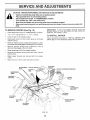
MOWER
IMPORTANT:
IF AN ATTACHMENT
MOWER DECK S TO BE MOUNTED
REMOVE THE FRONT LINKS.
(See Fig. 16)
Place attachment clutch n "DISENGAGED"
position.
Turn _--,7ht adiustment knc' *- '-w_ _'_setting.
Lower mower to _ts Iowesl oos_non
Disconnect clutch rod from clutch
retainer spnng.
TO INSTALL
OTHER THAN THE
ON THE TRACTOR
MOWER
Fellow procedure described n "INSTALL MOWER AND
DRIVE BELT" in the Assembly section of this manual.
ever by removiBg
Remove retainer spring holdtng anu-swaycar [o cnassis bracket and disengage antl-swaybar from bracket.
Remove retainer springs from suspension
OeCKana disengage arms frorr deck.
Raise attachment
arms at
lift to its hignest positior
Remove two retainer spnngs from each front link and
remove links,
Slide mower forward and remove belt from engine
9ulley.
Slide mo_ er out from unoer r_ght side of tractor.
ADJUSTMENT
NUTS
RETAINER
SPRING
CLUTCH
FRONT
SUSPENSIO_
ARMS
IGINE
PULLEY
"_"_'_'_
LINKS
_X
FRONT
SUSPENSION
BRACKET
\
RETAINER
/
RETAINER
SPRING
/
ANTI-SWAY
BAR
FRONT MOWER
,
RETAINER
SPRINGS
FIG. 16
2O
BRACKET
SERVICE AND ADJUSTMENTS
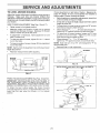
TO LEVEL
MOWER
HOUSING
Check ac.ustmem on right side of tractor. Measure distance "F" directly in front of and behind the mandrel at
bottom edge of mower housing as shown.
Before making any necessary adjustments, check that
both front links are eaual in length.
tf links are not eaual in length, adjust one link to same
ength as other link.
To lower front of mower housing, loosen nut "G"on both
front inks an equal number of turns
Whend_stance F"_,J.7_, _,_,/2"loweratfrontthanrear.
tighten nut "H" against trunnion on both front links
To raise front of mower housing, loosen nut "H" from
trunnion on bOth front links. Tighten nut "G" on both
front links an equa number of turns.
Whendistance"F"is
'°J'to_/2"loweratfro
_.-- _r.
t_gnten nut "H" against trunnion on both front links.
NOTE: Each full turn of nut "G" wilI change dim. "F" by
auuroximately 3/8",
Recheck s_de-to-slde aojustmen[.
Adjust the mower while tractor is parked on level ground or
driveway.
Make sure tires are propedy inflated (See
"PRODUCT SPECIFICATIONS" on page 3 of this manual).
If tires are over or underinflated, you will not properly adjust
your mower
SIDE-TO-SIDE ADJUSTMENT (See Figs. 16 and 17}
Raise mower to _ts nighest pos=t=on
Measure height from 3ottom of deck cur to grouna
evel at front corners of mower. Distance "A" on both
sides of mower should be the same.
If ac_ustmem is necessary,
side of mower only.
make aajus[mem on Dne
To raise one side of mower, tighten lift _:nKa_" ,stmen[
nut on that side
To lower one side of mower, loosen lift link adjustmem
nut on that side.
NOTE: Each fult turn of a@ustment nut will change mower
height about 3/16".
Recheck measurements
.
after adjusting.
BOTTOM
j
MANDREL
BOT10M
OF C_
!_O//_
FiG. 18
CURL
BOTH FRONT LINKS MUST BE EQUAL IN LENGTH
"-"--------_-
GRO U N U LINE//
FIG. 17
FRONT-TO-BACK
ADJUSTMENT
(See Figs. 18 and 19) IMPORTANT:
DECK MUST BE LEVEL SIDE-TO-SIDE.
IF
THE FOLLOWING
FRONT-TO-BACK
ADJUSTMENT
S
NECESSARY.
BE SURE TO ADJUST BOTH FRONT LINKS
EQUALLY SO MOWER WILLbFAY
LEVELSIDE-TO-StDE
To obtain the 0esl cut_mg results, the mower housing
should be ad.usted so the f ro;-t is approximately 1/8" to 1/2'
lower than me rear wnen the mower s " [s highest
DOSltlOn.
FIG. 19
21
ERVICE AND ADJUSTMENTS
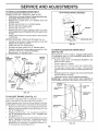
TO REPLACE
MOWER
DRIVE
BELT
WITH PARKING
BRAKE ,ENGAGED"
MOWER DRIVE BELT REMOVAL (See Fig. 20) Park tractor on a level surface, Engage parking brake.
Disengage attachment clutch control.
=
Remove four screws from L.R. mandrel cover and
remove cover.
•
Roll belt over the top of L,H. mandrel pulley.
•
Remove belt from engine pulley.
Remove belt from idle_ "" "_"_,
•
NUT "A"
JAM NUT
Remove any dirt or grass clippings which may have
accumulated around mandrels and entire upper deck
surface.
Check Dnmary laler arm ang two idlers to see that they
rotate freely,
DPERATING
MOWER DRIVE BELT INSTALLATION (See Fig. zO} Install belt in both idlers. Make sure belt is _nDotn Delt
keepers at the idlers as shown.
Install new belt onto engine eutley.
Roll belt nto upper groove of L.H. manure pulley.
Carefully check belt routing making sure belt is _nthe
grooves correctly and inside belt keeeers
Reassemble L.H. mandrel cover.
L.H.
MANDREL
SCREWS
IDLER
PULLEYS
FIG. 21
TO REPLACE
MOTION
DRIVE
BELT
(See Fig. 22)
Park the tractor on level surface, Engage parking brake.
For assistance, there is a belt installation guide decal on
DOttom side of left footrest.
Remove mower See "TO REMOVE MOWER" in this
section of this manuaQ
Remove UDDer pelt Keeper.
Remove belt from stationary idler and clutching idler.
Pull celt SlaCK toward rear of tractor. Remove belt
upwards from transaxle pulley by deflecting belt keepers.
Pull belt toward front of tractor and remove downwards
from around on j_ne pulley.
Install new belt by reversing above procedure.
IMPORTANT:
MAKE SURE UPPER BELT KEEPER IS
POSITIONED PROPERLY BETWEEN LOCATOR TABS.
ENGINE
PULLEY
COVER
PRIMARY
DLER ARM
MANDREL
ENGINE*"'---..
PULLEY
MOWER
DRIVE
BELT
BELT
KEEPERS
TABS
CLUTCHING
IDLER
FIG. 20
KEEPER
TO ADJUST
BRAKE
ARM
STATIONARY
IDLER
(See Fig. 21)
Your tractor is eauiDeeo w_th an aojustaD_e DraKe sy _tem
which Is mounted on the right side of the trar _axle
If tractor reaulres more than s_x _6) feet stopping u_stance
at hign speed in highest gear. then brake must be adjusted.
Depress clurcn/DraKe eeua_ ana engage parking DraKe.
Measure alstance between brake operating arm ana
nut "'A" on DraKe roa.
If distance _sother than 1-1/2'. loosen jam nut ana turn
nut "A" umn alstance becomes 1-1/2". Retighten jam
nut against nut "A".
Road test tractor for proper stopping distance as stated
aeove Readfust if necessary. If stopping distance is
st greater man s_x 6} feet in h_§'_est gear runner
maintenance is necessary Contact your nearest authorized service centeddeeartment
TRANSAXLE
PULLEY
FIG. 22
22
I
RVICE AND ADJUSTMENTS
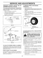
TRANSAXLE
SHIFTER
LINKAGE
JUSTMENT
(See Figs. 23 and 24)
AND
AD-
TO REMOVE WHEEL
(See Fig. 25)
FOR REPAIRS
Block up axle securely.
The transaxle should be in neutral when the gear shift lever
_sin the neutral (N) (lock gate) position. The adjustment _s
oreset at the factory; qowever, if adjustment is needed
3roceed as follows:
={emove axle cover, retaining ring and washers to allow
wheel removal [rear wheel contains a square key - Do
not ioseL
Make sure transaxle is in neutral fN/.
Repalr tlre and reassemble
Loosen two Iocknuts on tie rod.
On rear wneels only: align grooves rn rear wheel hub
ana axle, nsert square Key.
Turn center rod until gearshift lever fails into neutral
ock gate on fender console.
Replace washers and snap retaining nng securely
axle groove.
Reelace axle cover.
Tighten Iocknuts secure y.
n
WA£;!ERS
r.....-.,---GEARSHIFTLEVER
RETAINING
RING
LOCKGATE
\
NEUTRAL
\
FIG. 23
AXLE
COVER
SQUARE KEY
'REAR WHEEL
LOCKNUTS
FiG. 25
CENTER
TIE ROD
ONLY)
TO START ENGINE
See Fig. 2{})
ROD
WITH A WEAK
BATTERY
CAUTION: Lead-acid barfs,ties 9enerate explosive gases. Keep sparks, flame
and smoking materials away from batteries.
Always wear eye protection
wl-en around batteries.
ZZ_
TRANSAXLE
/
!_ 'our battery is too weaK to star[ the eng qel it should "e
"ecnargea,
I 'jumper
cables" are useo for emergency
starting, follow rn_s oroceaure:
MPORTANT
YOUR TRACTOR
S EQUIPPED
WITH _,
12 VOLT NEGATIVE GROUNDED
SYSTEM
THE OTHER
VEHICLE
MUST
ALSO
BE _' I2 VOLT
NEGAq VE
GROUNDED
SYSTEM
DO NOT USE YOUR TRACTOR
BATTERY TO START OTHER VEHICLES
FiG. 24
TO ADJUST
STEERING
WHEEL
TO ATTACH JUMPER CABLES
Connect each end of me RED cable tc the POSITIVE
•- terminal of each batten,,, taking care not to shot1
agatnst cnassls
Connect one ena of the BLACK cable to the NEGATIVE - terminal of fui y charged battery.
ALIGNMENT
If steering wheel crossbars are not nonzonta (left to right
when wheels are positioned stralgnt forward remove steering wheel and reassemble oer rest ructions in the Assembly
section of this manual.
FRONT WHEEL
Connect me omer end ot the BLACK cable [o good
CHASSIS GROUND away from fuel tank and battery.
TOE-IN/CAMBER
The front whee toe-in and cameer are not aulustab_e on
your tractor. If damage nas occurrec to affect me front
wneel toe-in or camber contact your nearest authorized
service cemer/aeuartment.
TO REMOVE CABLES
REVERSE ORDER-
BLACK cable first from chassis and then from the fu{ly
cnarged battery,
RED cable last from bOth u_,ttenes
23
SERVICE
ADJUSTMENTS
_HOOD
/
"POSITIVE"
"NEGATIVE"
(+)
HEADLIGHT
WIRE
CONNECTOR
_-J
I L.H. PANE_I
|
•
BOLT
3
] _--_,
t'
0
FIG. 27
ENGINE
FiG. 26
TO REPLACE
HEADLIGHT
TO ADJUST THROTTLE
(See Fig, 28)
BULB
Pul bulb holder out of the hole m the Backside of the
grill.
Replace DUIOIn hOlder and push DUIDnolaer secure,
back into the ho_e n tile backs:de of the grit
Close hood.
AND
With eng ne nor running, move tnrottie centre lever to
fast (,1_,)oosmon.
Check that swivel is against side of quarter circle. If it
is not. loosen cable clamp screw and pull cable back
unt swive s against auarter circle. Tighten cable
_._, ip screw securely.
RELAYS
Loose or damaged wiring may cause your tractor to run
poorly, stop running, or prevent it from starting.
CLAMPSCREW
Check wiring. See electrical wiring diagram in the
Repair Ports section of th s manual
TO REPLACE
TO REMOVE
(See Fig.
HOOD
AND
GRILL
.f'_--'__
Y,
FUSE
Replace w_m 30 amo au_omotwe4ype p_ug-in fuse
fuse holder is located benmna the dash,
CABLE
The throttle control nas been oreset at the factory and
adjustment should not be necessary. Check ad ustment as
described De=ow oefore loosening cable. "adjustment
s
necessary, proceed as follows:
Raise hood.
INTERLOCKS
CONTROL
QUARTER
CIRCLE \
The
ASSEMBLY
27)
Raise hood.
UnsnaD neaa ght w_re connector.
Stand in front of tractor. Grasp hood at sides titttoward
engine and lift off of tractor•
?
_
SWtVEL
To replace reverse aoove oroceeures.
FIG. 28
TO ADJUST
CHOKE
CONTROL
(See Fig. 29)
The cnoKe centre nas eeen oreset at tne factory aria
aojus_ment should not be necessary. Check adjustment as
aescrlDec below before loosening cable. If adjustment IS
necessary uroceea as fc ow,s
24
SERVICE
ADJUSTMENTS
With engine not running, move choke control (located
on dash panel) to full choke (Ikl) position.
While still holding throttle lever against idle speed
screw, turn idle mixture screw in (clockwise) unti
engine begins to die and then turn out (counterclockwise) until engine runs rough. Turn screw to a point
midway between those two positions,
Remove air cleaner cover, filter and cartridge plate to
expose carburetor choke (see "AIR FILTER" in the
Customer Responsibilities section of this manua0.
Continue to hold throttle lever against idle speea screw
and adjust _o_e seeed screw to obtain 900 to 1200
RPM. Release throttle lever.
Choke shouldbeclosed,
lfit isnot, oosencasingclamp
screw and move choke cable until choke is completely
closed. Tighten casing c_amp screw securely.
Reassemble a_r cleaner.
CHOKE
CLOSED
ACCELERATION
TEST -
Move throttle control lever from slow (,_) to fast (,_,)
position. If engine hesitates or dies. turn idle mixture
screw out ,counterclockwise
1/8 turn. Repeat test
and continue to adjusL if necessary, until engine accelerates smooth y.
_,
.High speed S,OD iS factory adjusted
Do not aajusz aamage may result.
IMPORTANT:
NEVER
TAMPER
WITH THE ENB NE
GOVERNOR
WHICH
q FACTORY SET FOR PROPER
ENGINE SPEED
OVERSPEEDINGTHEENGINEABOVE
THE
FACTORY
HIGH
SPEED
SETTING
CAN BE
DANGEROUS
IF YOU THINK THE ENGINE-GOVERNED
HIGH SPEED
NEEDS ADJUSTING.
CONTACT
YOUR
NEAREST
AUTHORIZED
SERVICE
CENTER/
DEPARTMENT
WHICH HAS PROPER EQUIPMENT
AND
EXPERIENCE
TO
MAKE
ANY
NECESSARY
ADJUSTMENTS
_CHOKE
LEVER
FiG. 29
TO ADJUST
31)
CARBURETOR
(See
Figs.
SCREW
30 &
The carburetor nas been oreset at me factory and adjustment should not De necessary, However. minor adjustment may De required to co mpensate for differences in fuel.
temperature, altitude or load. If the carburetor does need
adjustment, proceed as follows:
DLE SPEED
Ir =c,,eral. turning [he _,,,.....
screw in {clockwise decreases the supply of fuel to the engine gwing a leaner fuel/
air mixture. Turning the mixture screw out (counterclockwise} increases the supply of fuel to the engine giving a
richer fuel/air mixture.
IMPORTANT:
DAMAGE
SEATS
'4 CARBURETOR
TURNED tN TOOTIGHT.
PRELIMINARY
SCREW
TO THE NEEDLES
AND THE
MAY RESULT _= SCREW
S
FIG. 30
SETTING
Be sure you nave a clear air filter ana me mrottle
control cable ana cnoKe are aajustea properly ,see
aoove,.
IDLE SPEED
With engine off turn idle mixture screw in (clockwise)
closing it finger tight and then turn out (counterclockwise) 1-1/4 to 1-!/2 t!!ms.
_--'
- ./----(_-_
SCREW
FINAL SETTING Start engine and allow to warm for five minutes. Make
final adjustments with engine running and shift/motion
control lever in neutral (N) position.
With throttle control lever in slow (,_!) position, hold
throttle lever against idle speed screw and adjust idle
speed screw to obtain 1200 to 1400 RPM.
THROTTLE
LEVER
/
IDLE MIXTURE
SCREW
FIG. 31
25
STORAGE
ENGINE
Immediately prepare your tractor for storage at the end of
the season or if the tractor will not be used for 30 days or
me re.
FUEL SYSTEM
iMPORTANT:
IT IS IMPORTANT
TO PREVENT
GUM
DEPOSITS
FROM FORMING
IN ESSENTIAL
FUEL
SYSTEM PARTS SUCH AS CARBURETOR
FUEL FILTER
FUEL HOSE
OR TANK DURING
STORAGE.
ALSO
EXPERIENCE
INDICATES
THAT ALCOHOL
BLENDED
FUELS
CALLED GASOHOL
OR USING ETHANOL
OR
METHANOL
CAN ATTRACT
MOISTURE WHICH LEADS
TO SEPARATION
AND FORMATION
OF ACIDS DURING
STORAGE.
ACIDIC
GAS CAN DAMAGE
THE FUEL
3YSTEM OF AN ENGINE WHILE
N STORAGE
CAUTION: Never store the tractor with
gasoline in the tank inside a building
where fumes may reach an open flame
or spark.
AIlew the engine to cool
before storing in any enclosure.
TRACTOR
Drain the fuet tank.
Remove mower from tractor for winter storage. Whet"
mower s to be storea for a oenoa of hme clear' it tnoroughly, remove a air[. grease, leaves, etc. Store tr' a
clean, c 3/area.
Clean enti re tractor ,'See "CLEANING" in the Customer
Resaonsibilities sec: cn of this manu_ ,.
Start me engine ana let _1run until the fuel
carburetor are empty.
Never use engine or carburetor cleaner products ']the
fuel tank or permanent damage may occur.
Use fresh fuel next season
Inspect and replace belts, if necessary _See belt replacement instructions in the Service and Adjustments
section of this manual/.
NOTE:
Fue! stabmzer ts an acceotable alternatwe in
minim=zing the formation of fuel gum deposits during storage, Add staulltzer to gasc ine n fuel tank or storage
container, Always follow the mix ratio found on stabilizer
conta=ner, Run engine at least 10 minutes after adding
stabilizer to allow the stabilizer to reach the carburetor. Do
not drain the gas rank and carburetor if using luel stabilizer.
Lubricate as shown ntne Customer Responsibilities
section of this manual
Be sure that all nuts. bolts and screws are securely
fastened. Inspect moving parts for damage, breakage
ana wear. Replace if necessary.
Touch dO all rusted or cnlppea paint surfaces
ight y before painting.
ENGINE
sane
Fully charge the battery for storage.
CYUNDERS
After a perloa of time q storage, battery may reaulre
recharging.
Remove seark plug(s)
Pour one ounce of oil through spark _,,_,ghole(s) _mo
cylinder(s).
Turn ignition key [o "START" eosition for a Jew seconds
to distribute oil.
To held urevent corrosion and cower leakage during
long periods of storage, battery cables should be
disconnected and battery cleaned thoroughly (see "TO
CLEAN BATTERY AND TERMINALS" in the Customer Responsibilities section "this manual}.
Be sure batter,
OiL
Drain oil twttn engine warm an(] reolace with clean engine
o
See "ENGINE .... the Customer Respons_bflthes
section of tills manua ,.
BATTERY
After cleaning leave caDles disconnected
CableS where the_ cannot come in contact
terminals
nes aria
Reotace w_tn new E3ark p_ugLs).
ana place
WKn battery
OTHER
ara_n tube is secure y attached.
3o not store _asoline from one season to another.
f battery _s removea from tractor for storage, ac not
store battery olrectly on concrete or aarr 3 surfaces.
R_'_ce your gaso ne can if your can starts to rust.
Rust and/or dirt in your gasoitne wil cause prootems
f DOSSlb]e.store y-_ur tractor naoors aria caver [ u)
give protection from aust and dirt.
Cover your tractor with a suitable 3rotectwe cover that
aces not retarn moisture. Do no use etastlc. Plast_c
cannot breathe which allows condensation to form aria
will cause y }LJrtractor to rust
IMPORTANT NEVER COVER TRACTOR WHILE ENGINE
AND EXHAUST AREAS ARE STILL WARM
26
TROUBLESHOOTI
PROBLEM
CORRECTION
CAUSE
Will not start
1.
Out of fuel.
2.
3.
4.
5
6
Eng qe net"CHOKED"
Eng qe flooded
Bad spark plug
Dirty air filter
Dirty fuei filter
Water in fue
8
9
Loose or damagea wtnng.
Carburetor out of ad Js[mem
!0
Hard to start
propeny
8
!
Clutch/brake
2
3
4
_,ttachment clutch is engagea
Weak or dead DaEery.
Blown fuse.
5
6
8
9
Corroded battery terminals
_oose or aam_ _ea wrong
Faolb! _gntuon swl[cn
Fau% solenola or starter
=aulty opera[or presence swl[cr
Engine clicks but will not
start
1
2
3.
4
Loss of power
1
2.
',:
6
8
9
Fill fuel tank.
See "TO START ENGINE" in Operation
3.
4
5.
6.
Wait several minutes before attemoting to start
Replace spark plug.
Clean/replace air filter
Re_ ace fuel filter
Drain fuel tank and carburetc - refill tank with fresP
gaso,ne ann replace fuel filler.
Check a_Iwiring
Contact an authorized sewice center/deeartmenl
Contact an au[norlzea service cen_er/aeear_men_
5.
6
Check all wiring.
7.
Corltac'_
an
autpor_zed
service
center/departmenT
8
CorlTac_
an
aU[Forized
service
cen[e_/{]eDBLr[men!
aedaf not oepressea
_asohne.
g
Depress clutch/brake oeaal
Disengage aTtacnmem c_u[cn.
Recharge or reelace Da_ery
ReDlace fuse.
Clean batter_ _erm_na_s.
Check all wlnng
ChecWrep_ace _gnJ[fon swJ[cn.
ChecWreelace soleno_a or s_arter
Contact an authorized service cemer/aeE _r[men[
Weak or dead baEery.
Corroded battery terminals
Loose or aamagea wiring.
Faulty solenoid or starter.
1.
2.
3
4.
Recharge or reelace Dot[ely.
Clean Da_er_ [ermmals
Check all wiring.
Check/realace soieno_a or s[arter.
Cuttinc [oo mucn ]rass/too fast.
Throttle m CHOKE" oosmon
1.
2
Set in "Higher Cut oosl[ion/reGuce sDeed
AcJus_ :nroEle centre
C earl underside of mower housing
Clean/reel _ce air filter
CheCK oq level/c_ange o_
Clean anq regae or cnange sparK p_ug
ReDmce fuel filter
2
3
,_
o
esl.
Build*up or grass eaves ann _rasn unoer mower
Dirty a_r _ter
_ow oil levevalr[y ,_[
Fault, spark p_ug
Dirt_ fuel filter
Stale or d;rt, fue
Water _nfuel.
S
8
#
12
13
_
10
""
12
I_J
Engine valves ou_ of ad Jstmen[
15
13
1_
.'Dra_nh:e lank anu r_411with fresh gasoline
Dram fuel tank and carburetor refill tank wig fresh
gasoune aria replace fuel filter
Connect and tighten sParK DJLJO
w_re
Clean eng}ne a_r sc_een/fins
Clean/re#lace muffle_
Check all wiring
Contact an au_nonzed senace censer/eel
Cor]t
_cI at} aulhorized
service
cen[er/_er
2
Worn oenl or loose Diane
Bent blade manare_
2
Re[_ace blade.
Tigmen
Re[ ._c_ D_Oe m_ncJre
3
Loose/qamagea
]
Tighten
vibration
sectior
. can/roe ace air fill
ReDiace seark p_ug
Recharge or rep ace _3a[tery.
Reelace fuel finer
Drain rue lank ana reTlll with fres
..
3
SDatk ptug w_re 3ose
Dirty engine a_r screen/fins
Dirty/clogged muffler.
_oose or aamagea wrong.
Carburetor out of ad ]s[menL
1C
Excessive
1
2.
8
g
10
Engine valves ou[ of ad us[men[
DIrt_ air filter
Bad spark ptug
Weak or dead battery
Dirt_ fuel filter
Stale or did fuel
Loose or damagea wrong.
Carburetor out of adius[mem.
Engine va yes out of aa Js[men_
2
3
a
5
6.
Engine wilt not turn over
POINTS
part(s
27
9ose
Dartis
Dlaoe
R_.Dlace
3rfmen[
_r[mon[
DOll
aamagea
E E_rtS
TROUBLESHOOTi
POINTS
PROBLEM
CAUSE
Engine continues to run
when operator leaves seat
with attachment clutch
engaged
!.
Poorcut-uneven
t.
2
Worn bent or loose blade
Mower deck not leve
1.
2.
Replace blade. Tighten blade bolt.
LeveImower deck.
3
,i
Buildup of grass, leaves, ana _rasn unaer mower
Bent blade mandre
5
Clogged mower deck vent holes from buildup of
grass, leaves ana trasn arouno manarels
3.
4.
5.
Clean underside of mower housing.
Replace blade mandrel,
Clean around mandrels to open vent holes.
1.
Ob_,,_,[Ion
1.
Remove obstruction.
2.
3
z[
Worn/damaged mower dnve belt.
Frozen idler 9Ulley.
Frozen blade mandrel
2.
3.
4.
Replace mower dd,ve belt,
Replace idler pulley.
Replace blade mandrel.
1.
2.
3,
4.
Place throttle control in "FAST" position.
Shift to slower speed.
Allow grass to dry before mowing:
Level mower deck.
5
6
Engine sueed too s!ow
Travel soeeo too fast
Wet grass.
Mower deck no_ level
Low/uneven tire air pressure.
Worn, bent or loose blade.
7.
8.
Buildup of grass leaves and trash under mower
Mower drive Dell worn.
Mower bl=_L= wHJf*Ot
rotate
CORRECTION
Paultyopem_r-safe_
presence contmlsys[em
2.
3.
9.
10
_.....
ch mechantsm,
Blades improperb
qs_al_ea
imorocer blades usea.
Clogged mower aecK vent holes from buildun or
grass, leaves, ana trash aroune manarels.
5.
6.
7.
8.
9.
10
11
Check tires for proper air pressure.
Replace/sharpen blade. Tighten blade bolt.
Ctean underside of mower housing.
Replace mower drive belt.
Reinstall blades sharp edge downl
Replace with blades listed in this man_Jal.
Clean around mandrels to open vent holes.
1
2
Switch is "OFF".
Bulb(st uurnea ou[.
1.
2.
Turn switch "ON".
Replace bulb(s).
3
4
5
Faulty hgnt switch
Loose or aamaged wiring.
Blown fuse.
3.
4.
5.
Check/rep!ace light switch.
Checkwiring
and connections.
Replace fuse.
2.
Bad battery celJls},
Poor cable connections.
1.
2.
Replace battery.
Check/clean all conE,=btions.
3.
4.
Faugy regulator (if so equipped).
Faulty alternator.
3.
4
Replace regulator.
Replace alternator
1,
Engine throttle control not set _{t"SLOW"
position for 30 seconds before stopping engine
!
Move throttle control to "SLOW" position and allow
to ide for 30 econds before stopping engine.
Battery will not charge
Engine "backfires"
when turning engine
"OFF"
Check wiring, switches and connections, if not
corrected, contact an authorized service center/
department,
Poor grass discharge
Headlight(s} not working
(if so equipped)
1.
28
TRACTOR
- = MODEL NUMBER
9!7.251470
SCHEMATIC
RED
BLACK
BATTERY
.7-2)
FUSE 30 AMP.
STARTER
BLACK
SOLENOID
PEDAL UP)
IGNITION
WHITE
SEAT SWITCH
NOT OCCUPIED_
SWITCH
BLACK
I
)
--
--
I
3[AC_
NT C
CLUTCH OFF _
IGNITION
UNIT
BLAC_
GROUNDING
CONNECTOR
b--_)
.....
CHARGING
SYSTEM OUTPUT
3 AMP DC @ 3600 RPM
O
_HARGiNG
SPARK
_LUGS
,_C MIN _ 3600 qPM
SYSTEM DISCONNECTED
RED
LIGHTING
OUTPUT
L KC:I_
G
//
\
IGNITION
SWITCH
POSITION
CIRCUIT
OFF
M +G
ON
B+_
START
B _- S _
-_--
SYSTEM
DIODE
ALTERNATOR
NOTE
. .OLT5 A_ MIN _ 36U0 RPM JGHTS
YOUR TRACTOR IS
EQUIPPED WITH A SPECIAL
HEADLIGHTS
ALTERNATOR SYSTEM
THE LIGHTS ARE NOT
-)_.
CONNECTED TO THE
BATTERY BUT HAVE THEIR
HEADLIGHT
OWN ELECTRICAL SOURCE
SWITCH
or
BECAUSE OF THIS THE
OFF
--.
BRIGHTNESS OF THE LIGHTS
WILL CHANGE WITH ENGINE
SPEED AT IDLE THE LIGHTS
WILL DIM. AS THE ENGINE IS
WlRI NG INSULATED
CLIPS
SPEEDED UP THE LIGHTS
NOTE:
IF
WIRING
INSULATED
WILL BECOME THEIR BRIGHTEST.
NON-REMOVABLE
CONNECTIONS
s
REMOVABLE
CONNECTIONS
29
OFF
CLIPS WERE REMOVED
FOR
SERVICING
OF UNIT THEY
SHOULD BE REPLACED
TO
PROPERLY
SECURE YOUR WIRING.
REPAIR PARTS
TRACTOR
- - MODEL NUMBER
ELECTRICAL
917.251470
22
Z,J
4O
42
41
24
26
44
19
2O
33
32
35
31
49
3O
\
36
/
11
----
29
12
1
39
f
__""_'- 12
3O
REPAIR PARTS
TRACTOR
- = MODEL NUMBER
917.251 470
ELECTRICAL
KEY
NO.
PART
NO.
1 146140
2 74760412
3 STD551025
a STD551125
6 STD541025
7 7697J
8 7603J
9 109598X
10_14544=t_
11 145209
12 145769
f9 STD551125
20 73360400
21 136850
22 4152J
24 4799J
25 146148
26 108824X
28 145491
29 121305X
30 144921
31 140400
32 141228
33 140403
34 110712X
35 108236X
36 STD601005
38 140336
39
109553X
40
145489
41 71110408
42 131563
43 145673
_
73640400
45 121433X
49
153249
55
1749050b
70 140413
NOTE:
DESCRIPTION
Battery 12 Volt 30 amp
Bolt Hex Hd 1 '4-20unc X 3/4
Washer 9/32 X 5/8 X 16 Ga
Washer Lock Hvy Helica 1/4
Nut Fin Hex 1/4-20 Unc
Tube Plastic 46
Tray Battery 7 80 X 5 25 BIk
C[ame ;:ose O:;ve
Bolt RdHd Sqnk 1/4-20 x 7-1/2
Guard Terminal BIk
Nut Push Ny on 1/4 Battery
Washer Lock _/zL
Nut Jam Hex 1/4-20 Unc
Harness Asm Light W/4152j
Bulb Light #1156
Cable Ground 6 Ga olaCK
Cable Battery 6 Ga 22" rec
Fuse 30 &MP Auto Green
Cable Battery 6 Ga 21" black
Switch Plunger
Switch Ige 3 pos
Nut Ignttlon
Cover Sw Key BIk 1 25 Text SLT
Key ign Molded Craftsman Delta
Switch Light BIk BIk Rec
Bracket Switch CtutcP
Screw Tap Hex #10-24unc X 1/2
Bracket Switch Interlock
Switch Intlk Clutch Red 4 Term
Harness tgn B&S Dash HI Amm
Bolt Fin Hex 1 '4-20uncxl/2 Gr5
Cover TermlnaJ Red
Solenoid
Nut Kees Hex 1/4-20 unc
Ammeter Rectangular
Washer Pinned Delta
Sc._
ldrol 5 16-18 x 1/2 Ty_
Harness Eng,ne B&S
AILcomoonent u_mens]ons gwen in U.S inches
1 _ncn = 25.4----
31
REPAIR PARTS
TRACTOR
- - MODEL NUMBER
9!7.251470
CHASSIS
30
119
_.._14__24
_
87
38
29
_
/
/
7
36
36
3
5
26
_
26
122 /
31
3 "_
44
9O
/
125
71
/-
/
66
/
9
115
3
117
/S
/
64
114
/
6
_--
86
3
- _%
_J
'_--._,_S
\
8
11
/ I
114
z _
117 3
_/"
118
/
/
S
108
--_'- 39
32
34
\v
26
3
REPAIR PARTS
TRACTOR
- = MODEL NUMBER
917.251470
CHASSIS
KEY
NO,
PART
NO.
I
2
3
6
8
9
10
11
13
14
17
24
25
26
145501
140356
17490612
145206
126471X
145203
STD533710
145222
145221
17490608
136673X574
STD523710
19131312
STD541437
28
29
30
31
33
34
35
36
38
39
a4
45
47
50
59
64
65
66
71
73
74
86
87
90
108
"15
-14
"17
"18
-!9
120
121
122
!23
124
125
136373X428
136374
140002X574
137113
145244X574
145243X574
STD533707
108067X
139886
139887
140675
132257
105531X
137304
110436X
150272
74760532
140942X013
73640400
17580408
STD541437
136670X574
136671X574
STD551025
STD523707
121794X
145349
144283
145595
19092016
13727"
137269
137270
136814
136813
74180412
DESCRIPTION
Chassis Weldment
Draw Bar
Screw Thdrol. 3/8-16 x 3/4 T','-[_
Saddle
Clip msulatea
Dashboard
Bolt Carriage 3/8-16 x 1
Panel Dashboard LH
Panel Dashboard RH
Screw Thdrol 3/8-16 x 1/2
Hood Asm Pnt Srs YTGT Ms 674
Bolt Hex 3/8-16 x 1 Gr. 5
Washer 13/32 x 13/16 x 12 Ga
Nut Lock Hex W/Washer 3/8-!6
UNC
Grille YTGT 1-Pc
Lens Grille Bar
Fender
Bracket Fender
Footrest LH
Footrest RH
Bolt Carriage 3/8-16 x 3/4
Nut Pal
Bracket Assy Pivot LH
Bracket Ass_ Pivot #;4
Strip Asm Fender
Bezel HeadLigm
Nut Push
Rod Support Hood 1-Pc Zinc
Bushing Snap Spill
Dash Lower
BoltHex5/16-18x2
Gr 2
Plate
Nut Keos BIk Hex 1/4-20 UNC
Screw TaD Tite 1 '4-20 X 1/2
Nut Crownlock 3/8-16 UNC
Assy Panel Side RH
Assy Panel Side LH
Washer 9/32 x 3/4 x16 Ga
Bolt Fin Hex 3/8-16 x 3/4
Cover Access
Bracket Suuaort Dashboard
Washer Serrated
Bracket Clutch Mower
Washer 9/32X1-l/4X
16Ca.
Rivet Ratchet Female
Washer Nylon
Rivet Ratchet Male
Bracket LH
Bracket RH
Screw Machine Thrd
1/4-20 UNC "_3/4
NOTE: Att component dimensions given in US. inches
1 inch = 25.4 mm
33
REPAIR PARTS
TRACTOR
- - MODEL NUMBER
917.251470
DRIVE
115
57
\
\
31
88
/ 8i8681
19
72
84
70
66
/
/
65
J
64
58
40 _/_
__
,./
52
51
,/79
61
110
30
51
110
,S
111
61
62
35
77
110
36
/
34
37
-- _-_
54
25
\
19
28 _
24
""53
/
26
22
34
2_
116
REPAIR PARTS
TRACTOR
= - MODEL NUMBER
917.251470
DRIVE
KEY
NO.
PART
NO.
138788
2
3
4
5
6
110422X
121327X
STD582075
123787X
17490512
8
10
!1
13
15
19
21
22
24
25
26
27
28
29
3O
31
34
35
36
37
38
39
4O
41
42
44
45
46
47
48
49
50
51
52
123781X
STD561210
105701X
74550412
74490544
STD541437
106933X
145340
STD541237
126909X
STD551037
STD561210
145204
124236X
123780X
123791X
149001
120183X
STD551062
STD571810
123674X
STD523727
4470J
109070X
19131312
105706X
110812X
1200Cu39
127783
123789X
123205X
STD523715
STD541437
STD541431
DESCRIPTION
Transaxle, Peerless, 6 Speed,
Model Number 820-016B
Spring, Brake Return
Pulley, Transaxle
Ring, Retainer
Strap, Torque
Screw, Hex Washer Head, Thd.,
Roll. 5/16-18x3/4
Rod, Shifter
Pin, Cotter 1/8 x 1
Washer, Shift Plate
Bolt 1/4-28 UNF Gr. 8 W/Patch
Bolt, Hex FIghd 5/16-18 Gr. 5
Locknut 3/8-16
Knob
Roc Brake
Nut. Hex. Jam 3/8-16 UNC
Spring, Brake Rod
Washer 13/32 x 13/16 x 16 Ga
Pin. Cotter 1/8 x3/4
Roc Parking Brake
Ca_ Brake Parking
Bracket. Transaxte L.m.
Keeper. Belt. Transaxle. LH.
Shaft FootPeda
Bearing, Nylon
Washer 21/32 x 1 x 16 Gauge
Pin. Rol 3/16 x 1
idler. Flat
Bolt Hex Head 3/8-16 x 2-3/4
Spacer
Keeper, Belt
Washer 13 32 x 13/16 x 12 Ga.
Bearing
Washer. Hardened
Ring, Clip
Pulley. Idler. V-Groove
Bellcrank Asm. Clutch
Retainer Belt
Bolt Hex Head 3/8-!6 X 1-1/2
Nut. Crownlock 3/8-!6
Nut. Crownlock 5/16-18
KEY
NO.
PART
NO.
53
54
55
56
57
58
59
6!
105710X
126471X
105709X
STD523712
123796X
123792X
140312
17490612
62
63
64
65
66
70
72
74.
75
76
77
79
80
81
82
83
84
85
86
87
88
89
90
96
110
111
112
115
116
8883R
140186
71170764
STD551143
129921
134683
19132012
108097X
123800X
12000053
9396E
STD580025
123794X
123772X
!23782X
19171216
123793X
150360
71208
19212016
12000008
139992
124346X
STD624003
STD523707
123776X
STD551(J25
19132203
72! 10610
NOTE:
35
DESCRIPTION
Link, Clutch
Clip, Fuel Line
Spring, Return, Clutch
Bolt, Fin Hex 3/8-16 UNCx 1-1/4
V-Belt, Drive
Keeper, Belt, Transaxle, R.H.
Keeper, Chassis, Center Span
Screw, Hex Washer Head, Thd.,
Roll. 3/_. O ,.
Cover, Foot Pedal
Pulley, Engine
Bolt, Hex Head 7/16-20 x 4 Gr. 5
Washer, Lock
Keeper, Belt, Engine, L.H.
Guide, Belt, Mower Drive
Washer 13/32 x 1-1/4 x 12 Ga.
Spacer, Split
Washer 1-1/32 x 1-5/8 x 16
E-Ring
Key, Square 1/4 x 2
Key, Woodruff #9
Shift Arm
Shaft Assembly, Shifter
Spring, Torsion
Washer 17/32 x 3/4 x 16 Ga.
Rod Link Shift Adm. Non/Stretch
Nut, Lock Center 1/4-28 Fnthd
Bushing, Steering Rod
Washer 21/32 x 1-1/4 x 16 Ga.
Ring, Klip
Console 6sp GTV
Nut Self-Thd Wash-Hd 1/4 Zinc
Retainer Spring
Bolt, Hex Head 3/8-16 x 3/4
Bracket, Transaxle, RH.
Washer 9/32 x 3/4 x 16 Ga.
Washer !3/32 x !-3/8 x 3 Ga.
Bolt Rdhd Sq. Neck 3/8-16 x 1-1/4
All component dimensions
1 _nch = 25.4 mm
given in U.S. inches
REPAIR PARTS
TRACTOR
STEERING
-- MODEL NUMBER
917,251470
ASSEMBLY
"_J_-_'29
59 _>_
-_
F_
.
"_
_"
_
60
/
58 __
,,7
53
30 _
_"
42
62
48
30
46
8_
47
14
6_
46
j17
27
8
\
16
_
j7
15
18
16
32
j19
20_
/
//
j5
111
21_
22
j4
23 JJ
J
/
/
56
12
12
33/ /
29
!0
25
5
34
35/
I
8
36
REPAIR PARTS
TRACTOR
STEERING
917.251470
ASSEMBLY
KEY
NO.
PART
NO.
1
2
3
139768
142033
135227
135228
6266H
121748X
19272016
12000029
3366R
130468
STD55 t137
73610600
110,4-38X
74761060
73901000
132624
128758
57079
124035X
126684X
STD551125
71100410
12750"
109816X
124036X
136874
17490612
STD561210
5
6
7
8
9
10
11
12
13
14
15
16
17
18
19
20
21
22
23
24
25
27
29
30
- - MODEL NUMBER
KEY
NO.
DESCRIPTION
Wheel Steering Ayp/kelch Blk
Axle Asm Fr LT
SpindleAsmLH
SoindleAsm RH
Bearing Race Thrust t_aruen
Washer 25/32 X 1-5/8 X 16ga
Washer 27/32X1-1/4X"
3a
Ring Klip #t5304-75
Bearing ColStrg BIk
Link Drag Sol Ball Jt 20 064
Washer Lock Hvy HIcl Spr 3/8
Nut Fin Hex 3/8-24 Unf
Spacer Bearing Axle Front
BOLT Hex 5/8-11 Unc X 3-3/4
Nut Lock Flange 5/8-1" Unc
Pin Axle 5/8 X 1 55/1 54 Lg
Shaft Asm Strg
Washer Thrust 515x 750x 033
Support Shaft
Washer Shim 1/4 X 5/8 x 062
Washer Lock Hvy Hellca 1/4
Screw Cap Sckt Hd Phos & Oil
Shaft Asm Pittman
Nyliner Snap Ir
Srac_,eL c;teering
Gear Sector 22 Teeth
Screw Thdrol 3/8-16x3/4 Ty-tt
Pin Cotter 1/8 x 3/4
PART
NO.
31 138171
32 139929
33 19111216
34. STD551131
35 STD541531
36 145207
37 17541008
38 139769
39 100712K
40 STD541350
41
100711L
42 140216
43 121749X
45 149846
46 121232X
47 6855M
48 146841
49 131291
52 106451X
53 STD541437
56 19131210
58 17490508
59 !05663X
60 105664X
61
!22819X
62
149682
NOTE:
37
DESCRIPTION
E
,,, _vt Ma C! Lvr
Tie Rod
Washer 11/32x3/4x16Ga
Wasner Lock Hvy Hlcl Sur 5/16
Locknut 5/!6-24 UNF
Bushing Strg BIk 3/4 anc e
S,. ,_w Si'_,p#10-24 x l/,_ _ _
Cap Wheel Steer
Washer 53 X 2 25 X 160 Zinc
Nut Hex Jam ToDiock 1/2-20 Unf
Adapter Wheel Strg 758/753id
Column Steering
Washer 25/32 X 1 1/4 X 16 Ga
Knob Custom Oval
Cap Seindle Fr Top BIk
Fitting Grease
Lever Asm. Clutch Mower
Link Clutch W/Nibs
Bolt Shoulder
Nut. Crownlock 3 8-16 UNC
Washer 13/32 x 3/4 x 10 Ga,
Screw Thdrol 5/16 18 x 1/2 TT
_uEoortSaddleRear
10Ga.
Support Saddle Front
Screw Specia 3/8-16 x 3/4 Ty
Kit Steer Asm. 18.31 x 3/4
All component dimensions
1 inch = 25.4 mm
given in U.S. nches
REPAIR PARTS
TRACTOR
- - MODEL NUMBER
917.251470
ENGINE
J
38 _3
-/
14
"_
13
f
81
J
_
32
31
17
34
/
/
33
39
29
23
\
l
!
\
OPTIONAL
EQUIPMENT
Spark Attester
38
I0
REPAIR PARTS
TRACTOR
- - MODEL
NUMBER
917.251470
ENGINE
KEY
NO.
1
2
3
PART
NO.
132755
17720410
150469
4
5
6
7
8
10
11
12
13
14
15
16
17
23
24
25
26
27
29
31
32
33
34
37
38
149723
144068
144069
138129
150716
145552
STD551125
STD522507
272250
13280336
13200300
STD551237
17490624
128953
STD601005
138672
73920600
17541008
137180
151346
151296
123487X
106082X
8543R
39
40
41
81
109227X
3645J
139277
128861
NOTE:
DESCRIPTION
Control Throt RH BIk Pdl 36 60
Screw Hex Thd Cut 1/4-20x5 '8 T
Engine B&S. 20 HP. Model No.
460777 Type Number 1297-0Mu;fler A,_m Twi,-JLo--_ne
Exhaust Asm RH B&S 18 HP Vert
Exhaust Asm LH B&S 18 HP Vert
Clamp Tube Double Engine
Bolt 516-18UNCx3/4w/Sems
Shield Heat
Washer Lock Hvy Hehca 1/4
Bolt Fin Hex 1/4-20unc X 75
Gasket Muffler #272250
Nipple Pioe 4-1/2
Elbow Std 90 Degree 3/8-18 Not
Washer Lock Ext Tooth 3/8
Screw Thdrol 3/8-16 X 1-1/2 Tt
Shield Heat Browning
Screw TaD Hex #10-24 UNC x 1/2
Cc qtrol Choke 51.00 BIk W/bend
Nut Keos 3/8-24 Unf
Screw
Kit Spark Arrestor
Tank Fue
Cap Asm Fuel w/Gauge Vented
CIamp Hose Blk
Pad Spacer
Line Fuel 54
Plug Oil Drain cOrder From Eng ne
Manufacturer
Pad Idler
Bushing
Stem Fuel Tank
".IL,'_i
je 1/4-20 Starter Nut
All comoonent dimensions g ven in U.S ncn_s
"nch = 25.4 mm
39
REPAIR PARTS
TRACTOR
-- MODEL NUMBER
917.251470
SEAT ASSEMBLY
18
j9
14.
J
.5
6
7
22
J
21
J
1
\
17
KEY
NO.
PART
NO.
1
140122
140551
145006
STD541437
124181X
140552
121246X
121248X
72050411
134300
121250X
123976X
2
5
6
7
10
12
13
14
15
16
17
12
KEY
NO.
DESCRIPTION
18
21
22
23
24
25
26
27
28
Seat
Bracket Pnt Pivot Seat {blk
Clio Pus ....
Nut LOCKHex W/Ins 3/8 -16 UNC
Spring Seat Cprsn 2 250 BIk ZI
Pan Pnt Seat blk }
BracKet Pnt Mountinc Switch
Bushing Snap Blk Nyl 50 Id
Bolt Rdhd Sht Nk 1 4-20xl-3/8
Spacer SDIit 28 X 96
Spring Corsn
Nut Lock 1/4 Lge Fig Gr 5 Zinc
PART
NO.
124238X
153236
STD541431
74780814
19171912
127018X
STD551t5C
17490608
150176
NOTE:
40
Allcomeonenr
"tnch=25.4mm
DESCRIPTION
CaD Spring Seat
Bolt ShouIder 5/16-18 U qc Blkz-2A
Nut Lock Hex W/Ins 5/16q8
Bolt Fir_ Hex !/2-13 X 7/8 Gr 5
Washer -7/32 X _-3/16 X 12 Ga
Bolt Shoulder 5/16-18 X 62
Washer Lock Hvy HIcI Spr !/2
Screw Thdrol 3/8-16 x 1/2
Bolt 5/16 -!8 UNC X 3/4 W/Sems
almens_ons
given
< U.S.{ncnes.
REPAIR PARTS
TRACTOR
DECALS
- - MODEL NUMBER
917.251470
24
24
6
10
11
\
.2
8
22
,\
/
14
13
\
14
5
15
5
12
KEY
NO.
2
3
4
5
6
8
9
10
11
12
PART
NO.
138955
151696
151693
151694
106202X
133644
151799
145245
128314
150333
137537
4900J
WHEELS
8
DESCRIPTION
KEY
NO.
Deca Dash ins[ruc[_on Opera[ Eng
Deca Grille Lawn Tractor Dov
Deca Hood Rh Craftsman
Decal. Hood Lh Craftsman
Reflector. Taillight Red/Amber
Decal. Maint Custome" Sears Dom
D_''_ Panel Side B&S
Pad. Footrest
Decal Fender Craftsman White
Deca. CaD CNSMR Held Line SRS
Decal. Caution Englisb/SDantsn
Deca. Clutch/brake Enghsh
13
14
15
16
17
19
22
24
-----
PART
NO.
146046
151695
139346
140837
151795
138047
149516
138048
138311
145247
15_043
15231"
DESCRIPTION
Deca
/-belt Dr Sch Tractor E
Decal Chassis 6 Sp 44'
Decal. Mower Drive Schematic
Decal. Saddle Brake Parking
Decal Insert, Hood
Decal. Battery Diehard Sears
Deca. Battery
Decat. Panel Side Diehard White
Decal Lift Handle
Fastener, Poe-In Footrest
Manual Owner's (Enc ish_
Manua Owner's (Sean_sn}
& TIRES
KEY
NO,
PART
NO.
DESCRIPTION
5.8
4.10
/
/
2
3
/
/
3,9
5
6
11
6_
/
8
9
10
/
/
59192
65139
I06222X
59904
106732X427
278H
9040H
124074X427
124106X
7152J
104757X
144334
NOTE:
41
Cap Value Tire
Stem Value
]'ire F Ts 15 X 6 0 - 6 Service
Tube Inner Front #35060
Rim Asm 6"front White Service
Fitting Grease
Bearing Flanqe
r_ ,,_ Asm 12"rear White Service
Tire D Ts 23 x 8.5-12 Service
Tube Rear 9 5 X 8 Service
CaB Axle BIk 1 50 X 1 00
Sealant, Tire 10 oz. Tube_
A conDonen[ aimenslons
1 ncn - 25,4 mm
gwen in U,S _ncn_'s.
REPAIR PARTS
TRACTOR
- - MODEL
NUMBER
917.251470
SEAT
_2L
/7
26
"_f
...
/
/
23
35
41
\
I
1
t
36
22
14
\
38
3O
40
\
\
\
/
2
_12
13
19
\
13
t
-_
\
20
1718
15
,
\
20
1/
31
32
19
31
32
44
42
/
/
43
39 _'/
42
/
/
--20\\
¢
/
15
2O
REPAIR PARTS
TRACTOR
MOWER
- - MODEL NUMBER
917.251470
LIFT
KEY
NO.
PART
NO.
1 121006X
2 140673
6 74780624
7 125631X
8 122365X
9 122364X
!0 2876H
11 145537
!2
145536
13 STD824008
1_ 121002X
15 127218
16 73350800
17 130171
18 STD541450
19 139868
20 STD624008
21 19151216
22 12000037
23 110807X
24 STD551037
25 137150
28 STD560907
27 137167
28 STD541237
29 138057
30 110810X
31 140302
32 73540600
35 120529X
36 123933X505
37 123935X
38 17490512
39 142992
40 19112410
41 123934X
42 STD541437
43 19131612
44
STD533710
46 12000022
47
19292016
NOTE:
DESCRIPTION
Ro¢ Lever
Shaft. Lift
Bolt Hex 3/8-16 x 1-!/2
GriD. Handle
Button. Plunger
Plunger, Lever
Spring
Link. Lift. LH
Link. Lift. D_
Retainer. S_, ..j
Lever. Lift _'lncludes Key No. 1
Link Front
Nut. Hex. Jam 1/3-13 UNC
Trunnior B{k Zinc
Nut. Lock W/Wsh 1/2-13
Arm Susoenslon
Retainer Spring
Washer 15/32 x 3/4 x 16 Gauge
Klip Ring
Nut. Hex. Soecial
Washer 13/32 x 5/8 x 16 Gauge
Spring
Pin Cotter 3/32 x 1/2
Rod. Adjust Jft
Nut. Hex. Jam 2'8-1_
Knob qfin_te Height Adjustment
Trunnion
Bearing =vt Lift Spherical
Nut. Crownlock 3/8-24
Washer Nylon .44 x .75 x .032
3ointer Pnt Height Ind
Plug Hole Blk
Screw. Thdrol 5 16-18 x 3/4
Stop Over Center
Washer 11/32 x 1-1/2 x 13 Ga.
Scale Ind. Height BIk
Nut C'ownlocK 3/8-16 UNC
Washer 13/32x_ x 12Ga
Bolt Carriage 3/8-18 x 1.00
E-Ring
Washer 29/32x1-1/4,
16 Gauge
t, component d_mens[ons gven in U S ncnes
]ncn = 25.4 mrr
43
REPAIR PARTS
TRACTOR
MOWER
-- MODEL NUMBER
917.251470
DECK
\
46
7
/
4s
44
48
48
45
44
/76
45 f
sl/{
/17
31 "--.
40
45__.
_
27""_-_
65
2
2
45
2
6
54
\
\
16_
Y
44
22
REPAIR PARTS
TRACTOR
MOWER
- - MODEL NUMBER
917.251470
DECK
KEY
NO,
PART
NO.
1
2
3
4
5
6
7
8
9
10
11
12
13
140579
STD541431
STD533107
7631J
138457
STD624008
130832
850857
STD551137
140296
130652
129895
137553
14
15
16
17
18
19
20
21
22
23
24
25
26
27
29
30
31
32
33
34
35"
36
37
38
39
40
4!
42
43
44
45
46
137152
110485X
140329
106735X
19111016
105304X
123713X
137607
110452X
109785X
136321
19111216
STD533707
STD551037
STD541437
138776
137266
153535
129963
STD533712
STD533720
STD533710
137166
140365
131494
136572
STD551050
STD533107
136460
122052X
STD541437
74760628
DESCRiPTiON
Deck Asm.. Mower 44" Vented
Nut Crownlock 5/16-18
Bolt Carriage 5/16-18 x 3/4
Runner MowerLH
Bracket Asm.. Sway Bar
Retainer, Spnng
Arm Suseenslon. Roar
Bolt 3/8-24 x 1.25 Gr. 8 Patched
Washer. Lock Hvy 3/8 Unelated
Washer. Hard Blade Mower Vented
Blade (3 Reauired_
Bearing, Ball #6204 1Mandrel/
Shaft Asm.. W/Lower Brg tlncludes
Key No 12)
Housing, Mandrel 44" Vent
Bearing, Ball Mandre
Stripper, Mower Vented
Rod, Hinge
Washer 11/32x5/8x16Ga.
Cap, Sleeve
Spring, Torsion Deflector
Bracket, Deflector
Nut, Push
Sn_Q, L)efiector Mower
Runner, RH
Washer 11/32 x 3/4 x 16 Ga.
Bolt RDHD Sht SQNK 3/8-16 x 3/4
Washer 13/32 x 13/16 x 16 Ga.
Nut Crownlock 3/8-16 UNC
Screw, Thdrol. Hex Head
Nut, Fig Top Lock Cntr 9/16
Pulley, Mandrel
Washer, Spacer Mower Vented
Bolt, Carriage 3/8-16x 1-1/4
Bolt, Carriage 3/8-16 x 2
Bolt, Carriage 3/8-16 x 1 Gr. 5
Stiffener, Arm Idler
Keeper, Belt idler
Pulley, Idler Flat
Pulley, Driven
Washer !7/32xl
x16Ga
Bolt, Carriage 5/16-18 Unc x 3/4
Arm, Idler Secondary
Spacer, Retainer
Nut, Crownlock 3/8-16 Unc
Bolt, Fin Hex 3/8q6 Unc x 1-3/4
KEY
NO.
PART
NO.
47
48
49
50
51
82
53
54
55
56
62
63
65
66
68
69
70
71
72
73
74
75
76
77
78
79
80
81
82
83
84
85
86
87
88
89
90
91
101
--
137200
137729
136574
137272
137273
139245
137789
142686
131290
126910X
133943
72110612
151831
139622
140364
STD523707
140361
!33944
140367
139888
133940
131340
89180
133551
STD624003
140363
143354
STD541237
142028
146927
128903
12000029
!21748X
127845
127847
140333
128759
127498
106513X
143419
--
143651
NOTE:
45
DESCRiPTiON
Cover Mandrel RH
Screw. Thd Rol 1.4-20 x 5/8
Cover Mandrel LH
Arrr dler Primary
Sr_ring, Secondary
.... ey, idler V Groove
Shield. idler
V-Belt Mower Primary
V-Belt. Mower Secondary
Spring, Extensior
Washer Hardened
Bolt Carriage 3/8-16 x 1-1/2
Pulley Idler Falt Mower
Keeoer Belt Idler 50 Vent Dr.
Bracket Pvt 44" Mech.
Bolt Fin Hex 3/8-16 UNC x 3/4
Bracket .Support Brake 44" Mech.
Washer Hardened
Arm Asm Brake
Bolt Shld 5/16-18 Type TT
Roller Asm Cam Follower
Bolt Shldr 10_24 Zinc Gr. 5 42"
Nut Lock #10-24 UNC
Rod Pivot W/Nibs
Retainer Spring
Rod Clutch Secondary 44" Mech
Rod Clutch Primary 44" Mech
Nut H_'z lam 3/8-16 UNC
1 runnlon Adj '94
Spring Return
Bolt Shoulder 3/8-16 UNC
Ring Klip
Washer 25/32 x 1-5/8 x 16 Ga.
Keeper Spring
Arm Clutch Secondary
Arm Clutch Primary
Spring Clutch
Bushir/g
Washer Wear 16 Ga. Harden
Complete Mower (Standard Deck Order separately atl gauge wheel
components)
Mandrel Asm Servcie (includes 8!0, 12-15, 31 and 33)
All component dimensions given in U.S. inches
1 inch = 25.4 mm
REPAIR PARTS
TRACTOR
PEERLESS
TRANSAXLE
- - MODEL NUMBER
- MODEL NUMBER
917.251470
820-016B
21--
..J ,
"_1o
I
115
150
b...\..7
REPAIR PARTS
TRACTOR
PEERLESS
TRANSAXLE
- = MODEL NUMBER
= MODEL NUMBER
REF PART
NO, NO.
DESCRIPTION
-1
2
3
4
5
6
7
8
9
10
11
12
13
14
15
16
17
18
18A
20
21
22
24
25
25A
26
27
28
29
30
31
31A
31B
36
37
38
39
40
4!
42
42A
43
44
45
46
47
48
49
50
51
52
Transaxle Corrglete
Transaxle Cover
Needle Bearing
Transaxle Case
Countershaft ana 1. Gear 9 Teeth
Output Shaft
Output Gear, Steel, 35 Teeth
Spur Gear. Stdel. 15 Teeth
Shift Key
Shift Collar
Shift Fork
Bevel Gear. Steel. 33 Teeth
Input Bevel Pinion. Steel. 13 Teeth
Bevel Gear. Steel. 16 Teeth
Bevel Pinion. Steel. 10 Teeth
Ring Gear
Drive Block
Drive Pin
Neutral Spacer..350/.340 Thick
Netural Seacer..276/.268 Thick
Steel Bali. 5/16" Diameter
Set Screw 3/8-!6 x 3/8
Spring
Thrust Bearing
Screw 5/16-18 x 1-1/4
Screw 1/4-20 x 1-1/4
Retaining Ring
Retaining Ring
Retaining Ring
Washer
Washer
Washer
Washer
Washer
Brake Disk
Brake Pad Plate
Brake Pad (Package of 21
Dowel D_,_
Washer
Brake Lever
Screw 1/4-20 x 1-1/4
Screw 1/4-20x2-1/4
Locknut 5/16-24
Brake Pad Holder
Spacer
Brake Lever Bracket
Axle, 12-5/!6" Long
Axle, 16-3/16" Long
Spur Gear. Steel. 41 Teeth t_._
Spur Gear. Steel 35 Teeth (2q
Spur Gear. Stee 30 Teeth 13,/
Spur Gear. Steel 25 Teeth _'4,/
794513
772098A
780155
770088
776291
776275
778247
778253
792138
784216
784342
778246
778245
778198
778197
778248
786027
786019
786121
786122
792077
792078
792079
780071
792129
792073
792018
792018
788040
780072
780108
780128
780107
780042
790043
790007
799021
786026
792076A
790047
792073
792085A
792075
790025
786067
786086
774832
.774831
778216A
778206A
778205A
778204A
917.251470
820=016B
REF PART
NO. NO.
53
54
57
58
59
60
6"
65
66
67
71
71A
72
72A
79
81
778203A
778273
778199
778200
778201
778202
7782n8
780139
776274
776313
788069
792145
792165
788091
792144
786081
_2
83
84
87
88
89
90
96
97
98
99
100
101
102
103
104
105
106
_07
108
109
"'0
"" "
112
113
11z_
115
116
117
150
786082
786123
786131
788042
780119
780050
788067B
780084
780051
780165
788077
780166
774833
774834
792020
792006
780153
786144
780152
780150
792001
786142
788071
780168
786143
780151
786145
788070
780031
510334
DESCRIPTION
Spur Gear. Steel '>.2T,=eth f54
Spur Gear. Steel. 19 Teeth (64
Sour Gear. Steel. 15 Teeth (2,,)
Sour Gear. Steel. 20 Teeth (3./
Sour Gear. Steel. 25 Teeth (4°)
Sour Gear. Steel. 28 Teeth (5.1
Spur Gear. Steel. 31 Teeth (6-t
Washer
"3ut Shaft
Shifter and Brake Shaft
Sauare Cut Ring
Pushnut
Threaded Plug 9/16-18
"O" Ring
Spring
Roller Chain
Number 41 Chain. 24 Links}
Sprocket. 9 Teeth (Reverse)
SerocKel 18Teeth (Raverse',
Bearing Cap
Oil Sea 3/4
Bal Bearing
Ball Bearing
Grease Bentonite 32 Ounce Bottle
Thrust Bear'," j
Washer
Washer
"Q" Ring
Cupped Washer
Differential Carrid
Differential Carrier
Screw 1/4-20 x 2-1/4
Lock Washer
Washer
Sleeve
Needle Bearin j
Neec e Bearin
"0" Ring
_leeve
Sauare Cut Ring
Needle Bearing
Sleeve
Needle Bearing
Sleeve
Sauare Cut Ring
Needle Bearing
Gasket Eliminator
_ochte Number 515
Parts mus; oe orae "ed from Tecumseh
NOTE:
Allcomoonenialmenslonsg/en
" ncn - 25,4 ---
47
Products
_ U,S
Co
nches
REPAIR PARTS
TRACTOR
ENGINE
B&S - MODEL
NUMBER
- - MODEL NUMBER
460777,
TYPE NUMBER
48
917.251470
1297-01
REPAIR PARTS
TRACTOR
ENGINE
B&S - MODEL
NUMBER
-- MODEL NUMBER
460777,
TYPE NUMBER
917.251470
1297-01
534
642
165
535
235
445
284
I
1358 GASKET
SET I
[861 PUMP REPAIR KIT l
.
121 CARBURETOR
OVERHAUL K T
6634
19
49
REPAIR PARTS
TRACTOR
ENGINE
B&S - MODEL
NUMBER
- = MODEL NUMBER
460777,
TYPE NUMBER
917.251470
1297-01
615A o
116A
615A "_
O
819Ag
982
_08-1
1027
98
84
1032
305
978
_8
_78
73
_332
452
5O
REPAIR PARTS
TRACTOR
ENGINE
B&S - MODEL
NUMBER
- = MODEL NUMBER
460777,
TYPE NUMBER
917.251470
1297-01
783
615B
8O2
.°f,,'f'"_
j-'-
\
J
8_
51
REPAIR PARTS
TRACTOR
ENGINE
B&S - MODEL
KEY PART
NO. NO.
1
2
3
5-1
5-2
7-1
7-2
8-1
8-2
498583
397265
391086
214517
214518
271867
271868
495754
222892
9
10
10A
11
12
18
20
22
27803
94382
94830
280225
271703
271188
271189
94565
94239
498129
94196
492575
291675
94724
23
491180
24
25
27
28
29
32
33
34
222698
498584
498585
498586
498587
394959
394960
394961
394962
263129
498319
498314
95017
390420
263137
35
38
40
41
42
45
48
50
51
51A
52
65906
26828
221596
292260
494553
261368
214287
213290
271412
28141"
270884
13
!5
16
26
NUMBER
- - MODEL NUMBER
460777,
TYPE NUMBER
1297-01
KEY PART
NO. NO.
DESCRiPTiON
Cylinder Assembly
Bearing, Cyinder
Seal. Oil
Head. Cylinder Number 1
Head. Cylinder Number 2
..... Gasket. Cylinder Head Number 1
..... Gasket Cylinder Head Number 2
Breather Assembly Number 1
Cover. Breather. Cylinder Number 2
•Use with Key Number 572.
Air Ball
........
l_lng Holes)
..... Gasket. Valve Cover
Screw 4ex. Head
Screw. Sems
Tube. Breather
* Gasket. Crankcase Cover. 1 64"
* Gasket. Crankcase Cover .005"
Gasket. Crankcase Cover .009"
Screw, Cylinder Head
Plug. Oil Drain
Crankshaft
Key, Timing Gear
Base Assembly, Crankcase
* Seat Oil
Screw. Seres.
Crankcase Cover Mounting
Flywheel and Ring Gear Assemb,
MagneTo
Key, Flywheel
Piston Assembly, Standard Size
Piston Assembly, .010" Oversize
Piston Assembly, .020" Oversize
Pision Assembly, 030" Oversize
Ring Set. Piston. Standard Size
Ring Set. Piston..010" Oversize
Ring Set. Piston..020" Oversize
Ring Set. Piston..030" Oversize
LOCK Piston Pin
Pin Assy. Piston. Standard Size
Rod Assembly, Connecting
Screw Connecting Rod
Valve Exhaust
Valve ntake
Uses: 393606 Seal Assembl, ana
Retainer (Key Number 86_
Spring, ntake Valve
Spring, Exhaust Valve
Retainer. Intake Valve
Rotocoi Exhaust Valve
Retainer Exhaust Valve Rotocoit(2
TanDem.Valve
Gear. Cam
Manifold Intake
--" Gasket. Carburetor & ntake Elbow
Seacer. CamureTor
..... GasKet ntake Manifold Mounting
53
54
93970
93208
73
75
78
84
90
91
93
94
95
497908
222511
95039
91488
495009
495035
231209
491538
93499
96
97
98
99
102
103
104
105
107
!08
109
116
119
121
127
16165
187
188
201
202
263
205
206
207
209
209A
219
2t9P
220
222
221939
393469
91920
26157
271607
298514
230896
394683
491543
223534
392673
280474
94152
491539
223472
496599
94289
299146
94627
262683
262684
280997
93971
94298
262337
262352
261563
393415
394348
222773
491282
nctuded
--
DESCRIPTION
Screw. Sems, Carburetor Mounting
Screw. Sems.
ntake Manifold Mounting
Screen. Rotating
Washer. Spring
Screw Seres
Plug, Pine
Carburetor Assemb y
Body Assembly, Upper Carbure[or
Bushing, Throttle Shaft
** Valve Assemb]y, Carburetor Idle
Screw. Seres.
Throttle and Choke Valve Mounting
Valve TI_"ottle
Shaft and Lever. Throttle
Screw. Machine. Fillister Head
Spring, Throttle Adjustmenl
** Gasket. Carburetor Body
Float. Carburetor
** Pin Floc4 Hinge
** Valve Fuel Inlet
3ody, Lower Carburetor
Valve Choke
Shaft and Lever. Choke
O-Ring
Screw Seres. Hex Head
Carburetor Overhaul Kit
_lug, W.etch
- Cleaner
Nut. Wing
Line Fuel. 28" _Cut to Suit/
Screw. Hex Head
Link. Governor
Link. Throttle
Crank. Bel
Screw. Shoulder
Nut. Square
Sunnc Comoresslon
Spnng, Governor
Spring, Governo- _me
O S,nger Assembly
Gear Governor
Washer Thrust
Plate Assembly, Governor Centre
'_ GasKeT Set ,495868)
Inctudea in Carburetor Overhau
Kit t4915391
--"
ncluaea n both Gasket Set ,4958681. _na
Carburete" Overhaul Kit (491539,
....
mc_uaea - both Carburetor Overhaul Kit (491539)
ana Pump Repair Kit (3933971
.....
Inclu _ea - valve werhauI Gasket set 498047)
NOTE:
52
917.251470
A COmDCnent dimensions g yen in U.S. inches
" inch = 25.4 '_'_'_
REPAIR PARTS
TRACTOR
ENGINE
B&S - MODEL
KEY PART
NO. NO.
224 94297
227 491297
230 223882
235 224995
240 394358
244 230318
257 93897
258 94623
267 93897
284 94264
284A 94910
304
495587
305
94786
306-1 222846
306-2 223734
308-1 224774
308-2 224775
309 497596
310 94003
3!1 497608
332 230674
333 394891
334
337
356
358
363
380
383
387
392
394
414
422
432
434
435
445
474
482
510
523
524
525
528
534
535
537
544
552
552A
556
562
567
569
572
573
592
601
615
93381
802592
494705
495868
19203
62199
89838
280197
261395
272638
220680
222875
221377
223688
93829
394019
393474
93621
497606
494927
280860
495348
393815
94823
272490
271411
497603
262332
262331
93585
93853
9481_
272645
224816
491304
92278
93053
9429_
NUMBER
- - MODEL NUMBER
460777,
TYPE NUMBER
1297-01
KEY PART
NO. NO.
DESCRIPTION
Screw Pan Head
Lever Assembly, Governor
Washer Governor Crank qside
Shield. Spitback
=ilter. Fuel (In Fuel Line to Tank
Connector. Impulse PumP
Screw Sems
Screw. Sems
Screw. Hex Head
Screw. Hex Head
Screw. Hex Head
Housing, Blower
Screw. Sems
Shield. Cylinder
Shield. Cyhnder
Cover. Air Guide
Cover. Air Guide
Motor Starter
Bolt. Thru
Brush set
Nut. Hex
Armature GrouD.
MAGNETRON® Ignition
Screw. Sems. Armature Mounting
Plug, Spark. Resistor with Gasket)
Wire Ground
Gasket Set
Puller. Flywhee (Ouuona Accessory)
N_._E
Wrench. Spark Plug
Body, Pump
.... Spring, Pump
.... Diaphragm
Washer
Clamp, Oil Filler
.... Cap, Spring
Cover. Diaphragm
Screv Diaphragm Cover
Cartridge. Air Cleaner
Stator. Alternator DuaDCircuit
Screw. Sems
Drive Starter
CaD and Dipstick. Oi Filler
Sea. Filler Tube
Tube eli Filler
Imoulse Lme ana Clamo Assembly
Screw Round Head
Element Air Cleaner f
"-'Gasket
AirCleaner
Armature Starter
Lower Bushing, Governor
UpDer Bushing, Governor
Screw. Sems. Hex Head
Bolt. Governor Lever
Scre_ Hex Hd 3ack Plate re Cy naer
"Gaske{ Crankcase
Baffle Air. Cylinder Number 2
Back Plate Assembly
Nut. Hex
Clamo. Fue Line
Retainer. E-Ring
53
917.251470
615A
615B
616
634
634A
635
642
643
653
726
94900
263080
491530
271013
491287
66538
225008
496700
93585
391362
741
801
802
803
819
819A
842
847
851
858
859
860
861
868
868A
869
870
871
877
881
262989
394860
497607
497604
94675
94410
270920
495715
493880
270989
271025
261358
393397
273312
497656
261463
213316
261961
231218
393456
495901
955
978
979
982
1005
1006
1024
1027
1028
1032
1035
1090
397882
272060
492197
94362
281544
224901
492196
492932
491721
491710
492509
497605
qPM 3ettln]s:
DESCRIPTION
Retainer. E-Ring
Retainer
Crank. Governor
**Washer ThrotteShaft
. c._ _overnor Shaft
_-IDOW.Spark Plug
Cover. Air Cleaner
Cartridge Plate. Air Cleaner
Screw. Hex Head
Gear. Flywheel Ring
.... !ud_s Mounting P;
Gear. Timing
Cap, Drive
CaD End
Housing, Starter
Screw. Hex Heac
Screw Hex Head
* Sea Oil Filler Cap
Dipsuc_: ana Tube Assembly
Terminal ignition Cable
.... Diaphragm Damping
.... Gasket. Carburetor Pump
.... Spring ;2
Repair Kit. Pumo
Sea Intake Valve
Sea Intake Valve
Seat ntake Valve Standard
Seat Exhaust Valve. Standard
Guide. Exhaust Valve
Guide Intake Valve (See Manual)
Connector Assembly Dual-Circuit
Cover Plate. Crankcase
dncludes Gasket - Key #569)
J Seal. Solenoid
* Gasket. Adaoter
Cover. Oil Pump
Screw Hex Head
Fan. F ywheel
Retainer. Fan
PUmD. 0
Filter Ol
Starter Oil Filter
Ball O_ Pume
Shaft Pump
Retainer Brush
h'J_V:1100q400
High: 3200-3400
mcluaeo in Gasket Set 1495868)
Included in Carburetor OverhaL
Kit _491539)
_'_
Included in both Gasket Set ,495868/
Carburetor Overhaul Kit (491539)
....
ncluded m both Carburetor
Overhau
ano Pump Repair Kit (393397 _
.....
mciuaea in /alve overhau
NOTE:
ana
Kit 14915391,
Gasket set _498047t
a ;omeonent d_menslons given n U.S. Inches
"nch = 25.4 mm
SERVICE
NOTE_
54
SUGGESTED
GUIDE FOR SiGHTiNG SLOPES FOR SAFE OPERATION
-T _.
SIGHTING
GUIDE
ONLY RIDE UP AND DOWN
NOT ACROSS HiLL
SIGHT AND HOLD THIS LEVEL WITH
SKY LINE OR TREE.
Operate your Tractor up and down the face of slopes (not
greater than I 5°), never across the face. Make turns gradually to prevent tipping or loss of control.
Exercise extreme
caution when changing direction
on slopes.
HILL,
£RI:IFTSMI:IN
OWNER'S
MANUAL
20.0 HP
ELECTRIC START
44" MOWER
6 SPEED TRANSAXLE
GARDEN TRACTOH
MODEL NO.
917.251470
Each tractor nas its own mogel numoer.
ts own moclel numeer,
Each engine has
The model numeer for /our tractor wm be fount
"nodei plate located under the seat
on the
The model numoer for your eng ne w_ De found 3n the
blower housing of the engine.
All earls ISled nereln may De oraerea from any Sears,
Roebuck and Co. Service Center/Department and most Re_a Stores,
iF YOU NEED
REPAIR SERVICE
OR PARTS:
WHEN ORDERING REPAIR PARTS, ALWAYS
FOLLOWING iNFORMATiON:
FOR REPAIR SERVICE CALL
THIS TOLL FREE NUMBER
GIVE THE
, PRODUCT-TRACTOR
- MODEL NUMBER-917.251470
1-800-4-REPAIR
"ENGINE
(1-800-473-7247)
MODEL NO.-480777.
TYPE NO. 1297-01
• PART NUMBER
FOR REPLACEMENT PARTS
INFORMATION AND
ORDERING CALL THIS
TOLL FREE Ik LIMBER:
1=800-FON-PART
(1-800-388-7278)
• PART_RIPTION
Your Sears merchandise nas aaaea value wnen you
consider Sears has service units nationwide staffed wltlq
Sears trainee technlclanb,.,
orofessional
technicians
seecifica y trained to nsure that we meet our uteoge 1o
you we service what we se_
FOR CONSUMER ASSISTANCE
HOTLINE CALLTHIS
TOLLFREENUMBER
1-800-659-5917
154043
Rev. 1 04,08.96
KFSW
Printed
n U.S,A.