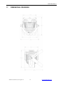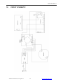
1
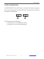
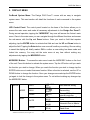
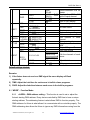
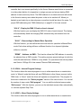
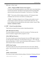
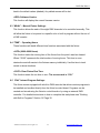
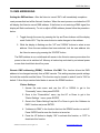
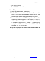
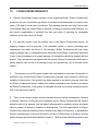
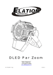
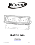
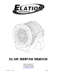
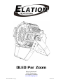
DLED Par Zoom
Elation Professional™
6122 S. Eastern Ave.
Los Angeles, Ca 90040
www.elationlighting.com
Rev. 03/24/2010 – visage
Version 1.2
DLED Par Zoom™
©Elation Professional, Los Angeles Ca.
1
www.ElationLighting.com
DLED Par Zoom™
TABLE OF CONTENS
1.
General Information……………………………………………………………………… 3
a. Introduction………………………………………………………………………. 3
b. Unpacking………………………………………………………..…………..… 3
c.
Customer Support…………………………………………….………………… 3
d. Warranty Registration……………………………………………………..…… 3
2.
Safety Instructions………………………………………………………........…………. 5
3.
Features……………………………………………………………………………………7
4.
General Guidelines………………………………………………………………………. 8
5.
Fixture Overview…………………………………………………………………………. 9
6.
Mounting and Installation………………………………………………………….……. 11
7.
Understanding DMX……………………………………………………………………... 14
a. DMX Cables……..………………………………………………………………. 14
b. DMX Terminator…………………………………………………………………. 15
c.
3-Pin to 5-Pin Conversion………………………………………………………. 16
8.
Display Indicators….……………………………………………………..……………… 18
9.
Display Menu….……………………………………………………..…………………… 19
10. DMX Addressing…………………………………………………….…………………… 24
a. Remote DMX Addressing (RDMX)……………………………………………. 24
11. DMX Traits…………………………………………………………………………………26
12. Working with Built-In programs…………………………………………………………. 30
13. Barn Door / Gel Frame Installation……………………………………………….……. 33
14. Cleaning and Maintenance……………………………………………………………… 34
15. Warranty…………………………………………………………………………………... 35
16. Photometric Data………………………………………………………………………… 37
17. Dimensional Drawings………………………………………………….……………….. 39
18. Circuit Schematic………...………………………………………………………………. 40
19. Technical Specifications…………………………………………...………….………… 41
©Elation Professional, Los Angeles Ca.
2
www.ElationLighting.com
DLED Par Zoom™
1. GENERAL INFORMATION
INTRODUCTION: Congratulations, you have just purchased one of the most innovative and
reliable LED fixtures on the market today! The DLED PAR ZOOM™ has been designed to
perform reliably for years when the guidelines in this booklet are followed. Please read and
understand the instructions in this manual carefully and thoroughly before attempting to
operate this unit. These instructions contain important information regarding safety during
use and maintenance.
UNPACKING: Thank you for purchasing the DLED PAR ZOOM™ by Elation Professional®.
Every DLED PAR ZOOM™ has been thoroughly tested and has been shipped in perfect
operating condition. Carefully check the shipping carton for damage that may have occurred
during shipping. If the carton appears to be damaged, carefully inspect your fixture for
damage and be sure all accessories necessary to operate the fixture have arrived intact. In
the event damage has been found or parts are missing, please contact our customer support
team for further instructions. Inside the box you should find: the fixture, a Power Cable, a
DMX XLR cable, a safety cable, and this manual. Please do not return this unit to your
dealer without first contacting customer support at the number listed below.
CUSTOMER SUPPORT: Elation Professional® provides a customer support line, to provide
set up help and to answer any question should you encounter problems during your set up
or initial operation. You may also visit us on the web at www.elationlighting.com for any
comments or suggestions. For service related issue please contact Elation Professional®.
Service Hours are Monday through Friday 9:00 a.m. to 5:00 p.m. Pacific Standard Time.
Voice:
(323) 582-3322
Fax:
(323) 832-9142
E-mail:
[email protected]
Forum:
www.ElationLighting.com/forum
Warning! To prevent the risk of fire and reduce the risk electrical shock, do not attempt to
operate this fixture with the lens cover removed.
Caution! There are no user serviceable parts inside this unit. Do not attempt any repairs
©Elation Professional, Los Angeles Ca.
3
www.ElationLighting.com
DLED Par Zoom™
yourself. Doing so will void your manufactures warranty.
Please do not discard the shipping carton in the trash. Please recycle whenever possible.
WARRANTY REGISTRATION: The DLED PAR ZOOM™ carries a two-year (730 days)
limited warranty. Please fill out the enclosed warranty card to validate your purchase. All
returned service items whether under warranty or not, must be freight pre-paid and
accompany a return authorization (R.A.) number. The R.A. number must be clearly written
on the outside of the return package. A brief description of the problem as well as the R.A.
number must also be written down on a piece of paper and included in the shipping
container. If the unit is under warranty, you must provide a copy of your proof of purchase
invoice. Items returned without a R.A. number clearly marked on the outside of the package
will be refused and returned at customer’s expense. You may obtain a R.A. number by
contacting customer support at (323) 582-3322.
©Elation Professional, Los Angeles Ca.
4
www.ElationLighting.com
DLED Par Zoom™
2. SAFETY INSTRUCTIONS
To guarantee proper and consistent operation, it is important to
follow the guidelines in this manual. Elation Professional will not
accept responsibility for damages resulting from the misuse of
this fixture due to the disregard of the information printed in this
manual.
1. Always be sure that the fan and the air inlets remain clean and are never
blocked. Allow about 6” (15cm) between this fixture and other devices or a wall
to allow for proper cooling. See page 12.
2. Never touch the fixture during normal operation.
3. Never look directly into the light source. You risk injury to your retina, which may
induce blindness.
4. For safe operation, follow the Installation guide described in chapter six of this
manual. Operating the DLED PAR ZOOM™ without suited safety aids such as
safety cables or clamps can increase the risk of damage and/or personal injury.
5. Qualified and certified personnel should only perform installation.
6. When mounting this fixture, use only the original rigging points included with this
fixture. Any structural modification will void the original manufactures warranty
and may increase the risk of damage and/or personal injury.
7. Do not attempt to operate this fixture if the power cord has become damaged or
frayed.
8. Never open this fixture while in use.
9. This device falls under protection-class I. Therefore it is essential that the device
be grounded properly.
10. Qualified personnel should perform all electrical connections.
11. Be sure the available voltage matches the voltage requirements of the unit. Be
sure the power cord is never crimped or damaged. If the power cord is damaged,
replace it immediately with a new one of similar power rating.
©Elation Professional, Los Angeles Ca.
5
www.ElationLighting.com
DLED Par Zoom™
12. Always disconnect from main power before performing any type of service or
any cleaning procedure.
13. Only handle the power cord by the plug. Never pull out the plug by tugging the
wire portion of the cord.
14. This fixture is designed for use indoors only, use of this fixture outdoors will void
the manufactures warranty.
15. Please be aware that damages caused by modifications to the device are
not subject to warranty.
Important Notice: Damages resulting from the disregard of safety and general user
instructions found in this user manual are not subject to any warranty claims.
©Elation Professional, Los Angeles Ca.
6
www.ElationLighting.com
DLED Par Zoom™
3. FEATURES
•
Low power consumption
•
Minimal heat emission
•
Maintenance free operation
•
Equipped with 36 3-Watt (10 x red, 16 x green, 10 x blue)
•
Silent Operation, convection cooled, no fans
•
100,000 hours rated LED life
•
Linear RGB Color Mixing, infinite color possibilities
•
Built-In Electronic Zoom (7˚ ~ 49˚)
•
USITT DMX-512 Complaint
•
Preprogrammed colored macros
•
Strobe-effect with a maximum flash rate of 18fps
•
DMX-controlled operation or stand-alone operation with Master/Slave-function
•
7 built-in programs can be called up via DMX-controller
~ 48 preprogrammed scenes per program
•
Sound-controlled via built-in microphone
•
8 Channel DMX Control
•
DMX-control via standard DMX-controller
•
Upgradable firmware via Elation “E-Loader” Data Pack
•
Electronic Switching Power Supply 100v~240v
•
Flicker-free operation for television and film
•
Durable Cast Aluminum Case Design
•
0%~100% Dimming (two dimming options; linear & standard)
•
Optional Accessories:
-
Barn Door Assembly
-
Frost Filter
©Elation Professional, Los Angeles Ca.
7
www.ElationLighting.com
DLED Par Zoom™
4. GENERAL GUIDELINES
This fixture is a professional lighting effect designed for use on stage, in nightclubs, in
theatres, and other types of architectural installations. Do not attempt operation or
installation without a proper knowledge on how to do so.
Consistent operational breaks will ensure that the fixture will function properly for many
years to come.
Do not shake the fixture around. Avoid brute force when installing or operating the fixture.
While choosing an installation location, please be sure that the fixture will not be exposed to
extreme heat, moisture, or dust. The minimum distance between the fixture and a wall or flat
surface should be at least 0.5 meter (about 1.5ft). See page 12.
Always install the fixture with an appropriately rated safety cable. When installing the fixture
in a suspended environment always be sure to use mounting hardware no less than M10 x
25 mm, also be sure the hardware is only inserted in the yoke’s mounting holes.
Do not attempt to operate this fixture until you have familiarized yourself with all of its
functions.
Do not permit operation by persons not qualified for operating this type of architectural
fixture. Most damages are the result of improper operation.
Please use the original packaging to transport the fixture in for service.
For your own safety, please read this user manual carefully before installing the device.
©Elation Professional, Los Angeles Ca.
8
www.ElationLighting.com
DLED Par Zoom™
5. FIXTURE OVERVIEW
1) Fixture Casing
2) LED Assembly
3) Yoke Assembly
4) Menu Button
5) Up Button
6) Down Button
7) Enter Button
8) Power input
9) DMX Output Jack
10) DMX Input Jack
1. Fixture Casing Assembly – Durable cast aluminum casing designed to take the
rigors of touring.
©Elation Professional, Los Angeles Ca.
9
www.ElationLighting.com
DLED Par Zoom™
2. LED Lens Assembly – The lens assembly may be user replaced in the event repair
is needed or a different beam angle is required.
3. Yoke Assembly – This yoke is designed to perform two functions; 1) When split it
can be used as a floor stand. 2) Used to secure a mounting clamp for truss mounting.
4. MENU Button – This button is used to access the fixtures menu functions.
5. Up Button – The up button is used to toggle forward through the menu functions and
settings.
6. Down Button – The down button is used to toggle backwards through the menu
functions and settings.
7. Enter Button – The enter button is used to enter in to a certain menu function or to
lock a menu setting in to memory.
8. Main Power Input– This power assembly provides main power to the unit and also
houses the intergraded safety fuse. Be sure to always use an approved power rated
IEC cable to feed power to the unit. In the event of fuse failure, always replace with
the exact same fuse unless otherwise instructed to do so by an authorized Elation
technician.
9. DMX Out Jack – 3-pin Male XLR connector. This lead is used to send an incoming
DMX signal to the next fixture in the DMX chain. Always use a proper DMX cable for
data transfer
10. DMX In Jack – 3-pin Female XLR connector. This lead is the main DMX input lead.
Always use a proper DMX cable for data transfer
©Elation Professional, Los Angeles Ca.
10
www.ElationLighting.com
DLED Par Zoom™
6. MOUNTING AND INSTALLATION
Cautions:
For added protection mount the fixtures in areas outside walking paths, seating areas, and
away from areas were unauthorized personnel might reach the fixture.
Before mounting the fixture to any surface, make sure that the installation area can hold a
minimum point load of 10 times the device’s weight.
Fixture installation must always be secured with a secondary safety attachment, such as an
appropriate safety cable.
To avoid injury, never stand directly below the device when mounting, removing, or servicing
the fixture.
Refer to regulations BGV C1 (formerly VBG 70) and DIN VDE0711-217
for proper installation in Europe To ensure proper installation, only
qualified staff should attempt installation.
Mounting points
Overhead mounting requires extensive experience, including amongst others calculating
working load limits, a fine knowledge of the installation material being used, and periodic
safety inspection of all installation material and the fixture. If you lack these qualifications, do
not attempt the installation yourself. Improper installation can result in bodily injury.
CAUTION!
Be sure a qualified electrician performs all electrical
connections.
Be sure to complete all rigging and installation procedures before connecting the main
power cord to the appropriate wall outlet.
©Elation Professional, Los Angeles Ca.
11
www.ElationLighting.com
DLED Par Zoom™
Mounting
The DLED PAR ZOOM™ is fully operational in any mounting position, hanging upside-down,
side mounted, or set on a flat level surface, etc. Be sure this fixture is kept at least 0.5m (1.5
feet) away from any flammable materials (decoration etc.). When clamp mounting; always
use and install the supplied safety cable as an added safety measure to prevent accidental
damage in the event of a clamp failure. See the image below.
Clamp Mounting
The DLED PAR ZOOM™ provides a unique mounting bracket assembly that allows the unit
to stand on a flat surface or to be hung on truss via a clamp in any safe position (see the
illustration above). Regardless of the mounting option you choose please be sure to refer to
©Elation Professional, Los Angeles Ca.
12
www.ElationLighting.com
DLED Par Zoom™
the safety guidelines in this manual to avoid damage to the unit and/or personal injury.
When mounting this fixture to truss be sure to secure an appropriately rated clamp to the
hanging yoke using a M10 screw fitted through the center hole of the hanging yoke. As an
added safety measure be sure to attach at least one properly rated safety cable to the fixture.
See illustrations below.
Securing the DLED PAR ZOOM™
Always be sure to secure your fixture with a safety cable when
suspending the unit from truss or other means. The fixture
provides a built-in rigging point for a safety cable as illustrated
above. Be sure to only use the designated rigging point for the
safety cable and never secure a safety cable to the hanging
bracket.
©Elation Professional, Los Angeles Ca.
13
www.ElationLighting.com
DLED Par Zoom™
7. UNDERSTANDING DMX
DMX-512: DMX is short for Digital Multiplex. This is a universal protocol used by most
lighting and controller manufactures as a form of communication between intelligent fixtures
and controllers. DMX allows all makes and models of different manufactures to be linked
together and operate from a single controller. This is possible as long as all the fixtures and
the controller are DMX compliant. A DMX controller sends the DMX data instructions to a
fixture allowing the user to control the different aspects of an intelligent light. DMX data is
sent out as serial data that travels from fixture to fixture via data “IN” and “OUT” leads
located on the fixtures (most controllers will only have output jacks).
DMX Linking: To ensure proper DMX data transmission, always use proper DMX cables
and a terminator. When using several DMX fixtures try to use the shortest cable path
possible. Never split a DMX line with a “Y” style connector. The order in which the fixtures
are connected in a DMX line does not influence the DMX addressing. For example; a fixture
assigned a DMX address of 1 may be placed anywhere in the DMX chain, at the beginning,
at the end, or anywhere in the middle. The DMX controller knows to send data assigned to
address 1 to that fixture no matter where it is located in the DMX chain. The DLED PAR
ZOOM™ can be controlled via DMX-512 protocol. The DLED PAR ZOOM™ is a fixture that
operates with 8 DMX channels (see pages 28-35 for the different DMX traits). The DMX
address is set electronically using the controls on the bottom of the fixture.
Data Cable (DMX Cable) Requirements (For DMX and Master/Slave Operation): Your
fixture and your DMX controller require a standard 3-pin or 5-pin XLR connector for data
input and data output (the illustration on the next page is of a 3-Pin XLR connector). If you
are making your own cables, be sure to use two conductor shielded digital DMX cable rated
at 120 ohms, this cable is designed for DMX transmission and may be purchased from your
Elation dealer or at most professional lighting retailers. Your cables should be made with a
male and female XLR connector on either end of the cable. Also, remember that a DMX line
must be daisy chained and cannot be split, unless using an approved DMX splitter such as
the Elation Opto Branch 4™ or DMX Branch/4™.
©Elation Professional, Los Angeles Ca.
14
www.ElationLighting.com
DLED Par Zoom™
Be sure to follow the above figure when making your own cables. Do not use the ground lug
on the XLR connector. Do not connect the cable’s shield conductor to the ground lug or
allow the shield conductor to come in contact with the XLR’s outer casing. Grounding the
shield could cause a short circuit and erratic behavior.
DMX-512 control connection
Connect the provided XLR cable to the female 3-pin XLR output of your controller and the
other side to the male 3-pin XLR input of the moving head (Please refer to the diagram
below.). You can chain multiple fixtures together through serial linking. The cable that should
be used is two conductor, shielded DMX cable with XLR input and output connectors.
Always be sure daisy chain your in and out data connections, never split or “Y” your DMX
connections unless you are using an approved DMX splitter such as the Elation Opto Branch
4™ or DMX Branch/4™.
©Elation Professional, Los Angeles Ca.
15
www.ElationLighting.com
DLED Par Zoom™
DMX-512 connection with DMX terminator
A DMX terminator should be used in all DMX lines especially in longer runs. The use of a
terminator may avoid erratic behavior in your DMX line. A terminator is a 120 ohm 1/4 watt
resistor that is connected between pins 2 and 3 of a male XLR connector (DATA + and
DATA -). This fixture is inserted in the female XLR connector of the last fixture in your daisy
chain to terminate the line. Using a line terminator (Elation part: DMX T PACK) will decrease
the possibilities of erratic behavior.
5-Pin XLR DMX Connectors. Some manufactures use 5-pin XLR connectors for DATA
transmission in place of 3-pin. 5-pin XLR fixtures may be implemented in a 3-pin XLR DMX
line. When inserting standard 5-pin XLR connectors in to a 3-pin line a cable adaptor must
be used, these adaptors are readily available at most electric stores. The following chart
details a proper cable conversion.
Fixture DMX addressing;
All fixtures should be given a DMX starting address when using a DMX controller, so the
correct fixture responds to the correct control signal. This digital starting address is the
channel number from which the fixture starts to “listen” to the digital control information sent
©Elation Professional, Los Angeles Ca.
16
www.ElationLighting.com
DLED Par Zoom™
out from the DMX controller. The allocation of this starting DMX address is achieved by
setting the correct DMX address on the digital display located on the back of the fixture.
You can set the same starting address for all fixtures or a group of fixtures, or set different
address for each individual fixture. Be advised that setting all you fixtures to the same DMX
address will subsequently control all fixtures in the same fashion, in other words, changing
the settings of one channel will affect all the fixtures simultaneously.
If you set each fixture to a different DMX address, each unit will start to “listen” to the
channel number you have set, based on the quantity of control channels (DMX channels) of
each fixture. That means changing the settings of one channel will only affect the selected
fixture.
In the case of the DLED PAR ZOOM™, which is a eight channel fixture, you should set the
starting DMX address of the first unit to 1, the second unit to 9 (8 + 1), the third unit to 17 (8 +
9), and so on.
Note: During start-up the DLED PAR ZOOM™ will automatically detect whether a DMX data
signal is being received or not. If a DMX data signal is being received, the display will show
"A.XXX" (XXX representing the actual DMX address). If the fixture is not receiving a DMX
signal the display will flash "A.XXX" (XXX representing the actual DMX address).
If your fixture is connected to a DMX controller and the display is flashing (not receiving a
DMX signal), please check the following:
-
The 3-pin or 5-pin XLR plug (cable with DMX signal from controller) may not be
connected or is not inserted completely into the DMX input jack.
-
The DMX controller is switched off or defective.
-
The DMX cable from the controller merging with included IP Rated Cable adapter is
not connected securely
-
The DMX cable or connector is defective.
-
A DMX terminator has been inserted into the last fixture in your DMX chain.
©Elation Professional, Los Angeles Ca.
17
www.ElationLighting.com
DLED Par Zoom™
8. DISPLAY LED INDICATOR.
The DLED PAR ZOOM ™ has a LED indicator on the display. This indicator is designed to
give a quick visual indication of the fixtures’ DMX status. The illustration below details the
functionality of the LED indicators.
The LED indicator represents DMX signal:
•
If the indicators is on, a clean DMX signal is present
•
If the indicator is off, there is no DMX signal present
©Elation Professional, Los Angeles Ca.
18
www.ElationLighting.com
DLED Par Zoom™
9. DISPLAY MENU
On-Board System Menu: The Design PAR Zoom™ comes with an easy to navigate
system menu. This next section will detail the functions of each command in the system
menu.
LED Control Panel: The control panel located on the base of the fixture allows you to
access the main menu and make all necessary adjustments to the Design Par Zoom™.
During normal operation, tapping the “MODE/ESC” key once will access the fixture’s main
menu. Once in the main menu you can navigate through the different functions and access
the sub-menus with the Up and Down buttons. Once you reach a field that requires
adjusting, tap the ENTER button to activate that field and use the UP and Down button to
adjust the field. Tapping the Enter button once more will confirm your setting. Once a setting
is saved the display will briefly readout OK to confirm a new setting has been made and
locked into memory. You may exit the main menu at any time without making any
adjustments by tapping the MODE/ESC button.
MODE/ESC Button - To access the main menu locate the MODE/ESC button on the front
of the unit. Press this button to activate the system menu. Tap the UP button until you reach
the function you wish to change. When you reach the function you wish to change tap the
ENTER button once to select that menu function. When a function is selected, use the UP or
DOWN button to change the function. Once your changes are made tap the ENTER button
yet again to lock the change in the system menu. To exit without making any changes tap
the MODE/ESC button.
0 MODE
A001~XXX
(AXXX)
ON/OFF
(SLAV)
VALU
ADDR
SLAV
RDMX
ON/OFF
ALON
(AU-A)
MAST
(AU-M)
ALON
(SO-A)
RUN
AUTO
SOUN
©Elation Professional, Los Angeles Ca.
19
DMX address setting
Slave setting
Change DMX address via
external controller
Automatic Run in Stand
Alone
Automatic Run as Master
Sound-controlled Run in
Stand Alone
www.ElationLighting.com
DLED Par Zoom™
MAST
(SO-M)
D–XX
(DXXX)
ON/OFF
ON/OFF
VALU
DISP
MIC
1 SET
2 MANL
3 TIME
4 EDIT
FAIL
FLIP
D ON
M-XX
OFF/HOLD/
AUTO/SOUN
No DMX Status
REST
DFSE
VER
<CH01>
~<CH08>
LIFE
ON/OFF
V-1.0~V-9.9
01 XX(00~FFH)
08 XX(00~FFH)
0000~9999(hours)
CLFE
ON/OFF
STEP
REC.
S–01 ~S–48
RE.XX
SC01
~ SC48
Sound-controlled Run as
Master
D-00 Display the DMX 512
value of each channel
Reverse display
Shut off LED display
Mic sensitivity
Reset
Restore factory settings
Software version
Test function of each
channel
Fixture running time
Clear fixture time *code is
“838”
Steps of Program Run
Auto Save Scene
FADE
0
1
Edit the channels of each
XX(00~FFH)
0
8 scene
XX(00~FFH)
XXX
Adjust fade time
CEDT
ON/OFF
C–01~C–08
Edit program via controller
Default settings shaded.
Remarks:
1) If the fixture does not receive a DMX signal the menu display will flash
repeatedly.
2) TIME: Adjust the hold time for each scene in built-in chase programs.
3) FADE: Adjust the fade time between each scene in the built-in programs.
9.1 “MODE” - Function Mode:
9.1.1
<ADDR> - DMX address setting – This function is used to set or adjust the
fixture’s starting DMX address. Every device controlled by DMX has to have a unique
starting address. The addressing feature is what allows DMX to function properly. The
DMX address of a fixture is what allows it to communicate with a controller properly. The
DMX addressing also allows the fixture to ignore any DMX information coming from the
©Elation Professional, Los Angeles Ca.
20
www.ElationLighting.com
DLED Par Zoom™
controller that is not meant specifically for the fixture. Because each fixture is connected
in a daisy-chain fashion it is imperative to assign a proper and unique starting DMX
address to each and every fixture. The DMX address is non-destructive and will remain
in the fixture’s memory even when the power to the unit is switched off. Memory is
backed-up and retain by an internal power source that should last about five years. For
proper DMX addressing see “DMX Addressing” on page 25 of this user manual.
“VALU” - Display the DMX 512 value of each channel
With this function you can display the DMX 512 value of each channel. The display
will automatically detail the changing DMX values as they are received from the
controller.
“SLAV” - Slave setting for Master/Slave Operation
With this function, you can define the device as slave for operation in Master/Slave
mode. Each slave setting will have a different function for a dynamic lightshow
without a controller.
“RDMX” - Address via DMX - This function allows the DMX address to remotely
be adjusted from a DMX console. This setting requires special settings for both the
controller and the fixture. RDMX is on by default. For operational instructions please
see Section 10/Page 25 of this manual “Remote DMX addressing.”
9.1.2 <RUN> - Internal Program Settings
This function allows the internal programs to run in either stand-alone or master/salve
mode. In “Master” mode the fixture will send DMX data to other fixtures connect via the
DMX chain. In “Alone” mode the fixture will operate as a single fixture. The program for
this mode is selected in the “Select program” section of the control menu. You can set
the number of steps under “Edit program”. You can edit the individual scenes under
“Edit scenes”. With this function, you can run the individual scenes either automatically,
i.e. with the adjusted Step-Time.
9.1.3 <DISP> - Menu Display Settings
This function allows the internal programs to run in either stand-alone or master/salve
©Elation Professional, Los Angeles Ca.
21
www.ElationLighting.com
DLED Par Zoom™
DMX chain. In “Alone” mode
“VALU” - Display the DMX 512 value of each channel
This function will electronically display the current DMX value for any channel that is
currently being adjusted. The display will automatically detail the changing DMX
values as they are received from the controller. This function is “off” by default.
“FLIP” – This function will flip the display readout by a 180˚ allowing for better
visualization when the fixture is mounted in an inverted position.
“D ON” – The display is designed to turn off during normal operation to avoid
excessive light in situations that require an extremely dark environment. This
function will adjust the time delay the fixture will remain on before it turns off. This
function is disabled as default.
9.2 “SET” – Fixture Personality Settings:
These functions set specific running modes and operating parameters.
<MIC> Microphone Sensitivity
This function adjusts the sensitivity of the built-in microphone. The fixture uses the
built-in microphone to trigger the built-in programs to sound.
<FAIL> DMX Fault Protection
This function dictates how the fixture will operate in the event DMX signal is suddenly
lost while operating in DMX mode. The three fail safe modes are; 1) “OFF” which will
blackout all light output. 2) “HOLD,” which will hold the last DMX command, or 3 “AUTO,”
which will put the fixture in sound-active mode.
<REST> Reset Function
This function resets the zoom motor and returns the motor to the “home” (starting)
position. Use this function in the event the zoom motor was physically bumped out of
place.
<DFSE> - Restore Default
This function is used to restore the factory settings of the device. All settings will be set
©Elation Professional, Los Angeles Ca.
22
www.ElationLighting.com
DLED Par Zoom™
back to the default values (shaded). Any edited scenes will be lost.
<VER> Software Version
This function will display the current firmware version.
9.3 “MANL” – Manual Fixture Settings:
This function allows the each of the eight DMX channels to be controlled manually. This
will allow the fixture to be preset to a specific color or built-in program without the use of
a DMX console.
9.4 “TIME” – Operating Hours
These functions will detail different time functions associated with the fixture.
<LIFE> (0000~9999 Hours)
This function tracks the running time of the fixture from the point it was last cleared.
Where “XXXX ”represents the total number of running hours. This time is none
destructive and will remain in the fixtures memory indefinitely. Use this time to track
rentals or show durations.
<CLFE> Clear Fixture Run Time
This function resets the run time to zero. The access code is “038.”
9.5 “Edit” Internal Program Settings:
The fixture comes equipped with a built-in DMX recorder that allows custom programs to
be installed and recalled directly from the fixture’s control board. Programs can be
created and stored using the fixture’s control board or by using an external DMX
controller. For detailed instructions on how to complete this task please see “Working
with Built-In Programs” Section 12/ Page 30.
©Elation Professional, Los Angeles Ca.
23
www.ElationLighting.com
DLED Par Zoom™
10. DMX ADDRESSING
Setting the DMX address - After the fixture is turned “ON” it will immediately complete a
reset process that test all the fixture’s functions. When the reset process concludes the LCD
will display the fixture’s current DMX address. If the fixture is not receiving a DMX signal, the
display will flash continuously. To set or adjust a DMX address, please follow the procedure
below:
1. Toggle through the menu by pressing the Up and Down buttons until the display
reads “Addr=XXX.” Tap the enter button to make changes to the address.
2. While the display is flashing use the “UP” and “DOWN” buttons to select a new
address. Once the new address has been selected, lock the new address into
the fixture’s memory by pressing the “ENTER” button.
The DMX address is non-volatile and will remain in the fixture’s memory even when the
power to the unit is switched off. Memory is backed-up and retain by an internal power
source that should last about five years
Remote DMX addressing (RDMX) / Address Via DMX- This function allows the DMX
address to be changed remotely from a DMX console. This setting requires special settings
for both the controller and the fixture. This function may be turned on and off, and is “ON” be
default. Follow the procedure listed below to access the RDMX functions:
Fixture Settings:
1. Access the main menu and use the UP or DOWN to get to the
“Personality” menu, then press ENTER
2. Once in the “Personalities” menu, tap the UP or Down to get to the
“Status Settings “ menu, press ENTER.
3. Once in the “Status Settings” tap the UP or Down to get to the “Address via
DMX” function and press ENTER.
4. “Address via DMX” is the function that turn the RDMX function on and off.
Press ENTER and be sure the function is turned on.
5. Press the UP button to display “ON” to activate this function, or “OFF” to
deactivate this function.
©Elation Professional, Los Angeles Ca.
24
www.ElationLighting.com
DLED Par Zoom™
6. Press ENTER to confirm.
7. Press MODE/ESC to return to the main menu.
Controller Settings:
1. Set the DMX value of channel 1 to a value of 7.
2. Set the DMX value of channel 2 to a value of 7 or 8. When channel 2 is
set to "7" you can adjust the starting address between 1 and 255. When
set to "8" you can adjust the starting address between 256 and 511.
3. Use channel 3 to set your desired DMX starting address. For example: If
you want to set the starting address to 57, set channel 1 to a value of “7,”
set channel 2 to a value of “7” and use channel 3 to set your address to
57 by selecting a channel value of 57. Example 2: If you want to set the
starting address to 420, set channel 1 to a value of “7,” channel 2 to "8"
and channel 3 to "164" (256+164=420).
4. Wait for approximately 20 seconds for the unit to complete the
address reset function.
©Elation Professional, Los Angeles Ca.
25
www.ElationLighting.com
DLED Par Zoom™
11. DMX TRAITS
DMX Operation Notes:
The fixture will function in DMX mode whenever the unit is receiving a DMX signal. Please
note that this will override all manual settings.
This unit will keep and retain the last DMX command in the event of DMX signal failure. To
reset the fixture you must turn the power off.
DMX CHANNEL TRAITS
The chart below outlines the different DMX.
©Elation Professional, Los Angeles Ca.
26
www.ElationLighting.com
DLED Par Zoom™
DMX channel functions and their values (8 DMX channels):
Channel
Value
Red:
1
0-255
Red (0-Black, 255-100% Red)
Green:
2
0-255
Green (0-Black, 255-100% Green)
Blue:
3
4
Function
0-255
Blue (0-Black, 255- 100% Blue)
Color macros:
!
0
No function
1-7
R02 Bastard Amber
8-15
R04 Medium Amber
16-23
R09 Pale Amber Gold
24-31
R316 Gallo Gold
32-39
R21 Golden Amber
40-47
R26 Light Red
48-55
R27 Medium Red
56-63
R36 Medium Pink
64-71
R339 Broadway Pink
72-79
R344 Follies Pink
80-87
R52 Light Lavender
88-95
R54 Special Lavender
96-103
R57 Lavender
104-111 R59 Indigo
112-119 R361 Hemsley Blue
120-127 R362 Tipton Blue
128-135 R64 Light Steel Blue
136-143 R67 Light Sky Blue
144-151 R68 Sky Blue
152-159 R69 Brilliant Blue
160-167 R76 Light Green Blue
©Elation Professional, Los Angeles Ca.
27
www.ElationLighting.com
DLED Par Zoom™
168-175 R79 Bright Blue
176-183 R80 Primary Blue
184-191 R382 Congo Blue
192-199 R87 Pale Yellow Green
200-207 R89 Moss Green
208-215 R91 Primary Green
216-223 L200 Double CTB
224-231 L201 Full CTB
232-239 L202 1/2 CTB
240-247 L119 Dark Blue
248-255 White
Internal programs:
!
5
0-10
No Function
11-40
Internal program 1
41-70
Internal program 2
71-100
Internal program 3
101-130 Internal program 4
131-160 Internal program 5
161-190 Internal program 6
191-220 Internal program 7
221-255 Gradient effect
Shutter, strobe:
!
6
0-31
All LEDs off
32-63
Led turn on
64-95
Strobe effect slow to fast
96-127
Led turn on
128-159 Pulse-effect in sequences
160-191 Led turn on
192-223 Random strobe effect slow to fast
224-255 Led turn on
7
!
General dimming/speed:
©Elation Professional, Los Angeles Ca.
28
www.ElationLighting.com
DLED Par Zoom™
0-255
!
Speed from slow to fast /when running internal programs
!
8
Dimming (0-Black, 255- 100% )
Speed from slow to fast /when running gradient effect
Zoom:
0-255
Continuous adjustment from near to far
©Elation Professional, Los Angeles Ca.
29
www.ElationLighting.com
DLED Par Zoom™
12. WORKING WITH BUILT-IN PROGRAMS
The fixture comes equipped with a built-in DMX recorder that allows custom programs to be
installed and recalled directly from the fixture’s control board. Programs can be created and
stored using the fixture’s control board or by using an external DMX controller. The following
instructions will detail the procedures for using the on-board system menu as well as using a
DMX compliant controller.
- Main menu 4
1. Press [MODE/ESC] to enter the main menu
(display flashing).
2. Press [UP] or [DOWN] button to select “EDIT”.
- Define the number of steps in Run
With this function you can define the number of
steps in the Program Run.
1. Select “STEP” by pressing [UP] or [DOWN]
button.
2. Press [ENTER], the display shows “S-XX”, “X”
stands for the total amount of steps you want to
save, so you can call up to 48 scenes in “RUN”. For
example if the “XX” is 05, it means that “RUN” will
run the first 5 scenes you saved in “EDIT”.
3. Press [ENTER] to confirm or Press [MODE/ESC]
to return to the main menu.
-Auto Save
With this function you can automatic save the number of steps in the Program Run.
1. Select “REC” by pressing [UP] or [DOWN] button.
2. Press [ENTER], the display shows “RE.XX”, “XX” stands for the number from 1 to 400.
©Elation Professional, Los Angeles Ca.
30
www.ElationLighting.com
DLED Par Zoom™
3. Press [ENTER] to confirm or Press [MODE/ESC] to return to the main menu.
Memory Statistics:
Quick Access Programs (Program Part): 3
Total Number of Programs: 10
Maximum Number of Steps (Scenes) per a Program: 64
Total Number of Scenes (Steps): 250
Step 1 – Building Scenes via Fixture Control Board.
The control will store a maximum of 48 scenes. These scenes are then used to create the
programs. A program can store one or a maximum of 48 scenes. Keep in mind that a scene
can only be access when it is stored in a “Program.” If you wish to build a static scene (a
scene consisting of no movement) for a logo or gobo projection, the scene must be stored
inside a program. To build a scene follow the instructions below:
- Editing the channels of the individual scenes
1. Select “SC01” by pressing [UP] or [DOWN] button.
2. Press [ENTER], the display shows “SCXX”, “X” stands for the scene no. to be
edited.
3. Change the scene no. by pressing [UP] or [DOWN] button.
4. Press [ENTER], the display shows “C-X”, “X” stands for the channel no. Such as
“C-01”, it means you are editing channel 1 of the selected scene.
5. Select the channel no. you would like to edit by pressing [UP] or [DOWN] button.
6. Press [ENTER] to enter editing for the selected channel, the fixture reacts to your
settings. The display shows the DMX value of the edited channel. Such as “11XX”, it
stands for in the channel 11 of the editing scene, the DMX value is XX , XX is a
hexadecimal number value “01-FF”.
7. Adjust the desired DMX value by pressing [UP] or [DOWN] button.
8. Press [ENTER] in order to edit other channels of this scene.
9. Repeat steps 5-9 until you finish setting all the DMX values for all channels of this
scene.
10. Once all the channels completed, the display will flash
“TIME”
11. Press [ENTER] to edit the time needed, the display shows “TXXX” , “XXX” stands for
©Elation Professional, Los Angeles Ca.
31
www.ElationLighting.com
DLED Par Zoom™
the time needed to run the current scene, value “001-999”. E.g., “002” means you
need 0.4ms (002*0.2ms) to run the current scene. Adjust the desired time by
pressing [UP] or [DOWN] button.
12. Press [ENTER] to save the settings for the scene you are editing, the display will
change to the next scene automatically.
13. Repeat steps 3-14 to edit and other scenes, you can edit and save a maximum of 48
scenes.
14. Press [MODE/ESC] to exit. The number of steps can be defined under “STEP” and
the scenes can be called up under “RUN”
Step 1B – Building Scenes from an External DMX Controller
The fixture includes a simple built-in DMX recorder. This recorder allows you to build a
scene using your own DMX console. That scene can then be sent to the fixture and be
stored inside one of the fixture’s scene storage banks. Many people may find this procedure
easier and quicker than using the on board menu functions as in “Step 1.” To store a scene
from an external DMX controller follow the procedures below:
1. Select “SC01” by pressing [UP] or [DOWN] button.
2. Press [ENTER], the display shows “SC01”.
3. Press [ENTER], the display shows “C-01”.
4. Select "CNIN" by pressing [UP] or [DOWN] button.
5. Press [ENTER], the display shows "OFF".
6. Press [UP] or [DOWN] button .the display shows "ON".
7. Press [ENTER], the display shows "SC02". You successfully downloaded the first
scene.
8. Adjust the Step-time as described above under point 12.
9. Call up the second scene in your controller now.
10. Repeat steps 5-11 until all desired scenes are downloaded.
11. Press [MODE/ESC] to exit. The number of steps can be defined under “STEP” and
the scenes can be called up under “RUN”.
©Elation Professional, Los Angeles Ca.
32
www.ElationLighting.com
DLED Par Zoom™
13. BARN DOOR / FILTER INSTALLATION
The DLED PAR ZOOM can be fitted with a barn door and gel frame for a frost filter. The
instructions listed below will detail the procedure for installing both options.
1. To install the gel frame holder only, simply rotate the retaining clip up and insert the gel
frame, then rotate the retaining clip down again to secure the gel frame in place.
2. To install the bar door assembly, loosen the two 4MM screws on the lens cover, then
attached the barn door assembly and tighten the screws.
3. When installing both the barn door and gel frame together, loosen the two 4MM screws,
then insert the gel frame followed by the barn door assembly and then tighten the
holding screws.
©Elation Professional, Los Angeles Ca.
33
www.ElationLighting.com
DLED Par Zoom™
14. CLEANING AND MAINTENANCE
Consider the following points during normal service and inspection:
1. Be sure all screws and fasteners are securely tightened at all times. Lose screws may
fall out during normal operation resulting in damage or injury as larger parts could fall.
2. Electric power supply cables must not show any damage, material fatigue or
sediments. Never remove the ground prong from the power cable.
Further instructions depending on the installation spot and usage have to be adhered by a
skilled installer and any safety problems have to be removed.
We recommend a frequent cleaning of the device. Please use a moist, lint- free cloth. Never
use alcohol or solvents.
There are no user serviceable parts inside this fixture, please refer all other service issues to
an authorized Elation service technician.
Should you need any spare parts, please order genuine parts from your local dealer.
©Elation Professional, Los Angeles Ca.
34
www.ElationLighting.com
DLED Par Zoom™
15.
2-YEAR LIMITED WARRANTY
A. Elation Professional® hereby warrants, to the original purchaser, Elation Professional®
products to be free of manufacturing defects in material and workmanship for a period of two
years, (730 days) from the date of purchase. This warranty shall be valid only if the product
is purchased within the United States of America, including possessions and territories. It is
the owner’s responsibility to establish the date and place of purchase by acceptable
evidence, at the time service is sought.
B. For warranty service, send the product only to the Elation Professional® factory. All
shipping charges must be pre-paid. If the requested repairs or service (including parts
replacement) are within the terms of this warranty, Elation Professional® will pay return
shipping charges only to a designated point within the United States. If the entire instrument
is sent, it must be shipped in its original package. No accessories should be shipped with the
product. If any accessories are shipped with the product, Elation Professional® shall have no
liability what so ever for loss of or damage to any such accessories, nor for the safe return
thereof.
C.
This warranty is void if the serial number has been altered or removed; if the product is
modified in any manner which Elation Professional® concludes, after inspection, affects the
reliability of the product; if the product has been repaired or serviced by anyone other than
the Elation Professional® factory unless prior written authorization was issued to purchaser
by Elation Professional®; if the product is damaged because not properly maintained as set
forth in the instruction manual.
D. This is not a service contract, and this warranty does not include maintenance, cleaning
or periodic check-up. During the period specified above, Elation Professional® will replace
defective parts at its expense, and will absorb all expenses for warranty service and repair
labor by reason of defects in material or workmanship. The sole responsibility of Elation
Professional® under this warranty shall be limited to the repair of the product, or replacement
thereof, including parts, at the sole discretion of Elation Professional®. All products covered
by this warranty were manufactured after January 1, 1990, and bare identifying marks to that
©Elation Professional, Los Angeles Ca.
35
www.ElationLighting.com
DLED Par Zoom™
effect.
E. Elation Professional® reserves the right to make changes in design and/or improvements
upon its products without any obligation to include these changes in any products
theretofore manufactured.
F.
No warranty, whether expressed or implied, is given or made with respect to any
accessory supplied with products described above. Except to the extent prohibited by
applicable law, all implied warranties made by Elation Professional® in connection with this
product, including warranties of merchantability or fitness, are limited in duration to the
warranty period set forth above. And no warranties, whether expressed or implied, including
warranties of merchantability or fitness, shall apply to this product after said period has
expired. The consumer’s and or Dealer’s sole remedy shall be such repair or replacement as
is expressly provided above; and under no circumstances shall Elation Professional® be
liable for any loss or damage, direct or consequential, arising out of the use of, or inability to
use, this product.
G. This warranty is the only written warranty applicable to Elation Professional® Products
and supersedes all prior warranties and written descriptions of warranty terms and
conditions heretofore published.
©Elation Professional, Los Angeles Ca.
36
www.ElationLighting.com
DLED Par Zoom™
16.
PHOTOMETRIC DATA
©Elation Professional, Los Angeles Ca.
37
www.ElationLighting.com
DLED Par Zoom™
©Elation Professional, Los Angeles Ca.
38
www.ElationLighting.com
DLED Par Zoom™
17.
DIMENSIONAL DRAWINGS
©Elation Professional, Los Angeles Ca.
39
www.ElationLighting.com
DLED Par Zoom™
18.
CIRCUIT SCHEMATIC
©Elation Professional, Los Angeles Ca.
40
www.ElationLighting.com
DLED Par Zoom™
19.
TECHNICAL SPECIFICATIONS
Power supply:
100v~240v / 50Hz~60Hz AC
Power consumption:
Maximum 120w
IP Grade:
IP44
LED Configuration:
36 x 3 Watt
(10 x Red, 16 x Green, 10 x Blue)
Weight:
7 Kgs / 15.4Lbs
DMX Channels:
8
DMX Drive:
Standard DMX-512,
3 pole IP Rated Locking Connector; [+] = Pin 3 [-] = Pin 2
[Ground] = Pin 1.
Color Mixing:
RGB Color Additive Mixing
Beam Angle:
Variable 7˚ ~ 49˚
Fuse:
GMA 220v~2A
Dimmer:
Continuous Dimming 0~100%
Strobe:
Electronic Strobe 0~18 Fps
Lamp Life:
100,000 Hours Rated Life
Dimensions:
(79 x 76.5 x 60) mm
31” x 30” x 23.6”
Please Note: Specifications and improvements in the design of this unit and this manual are
subject to change without any prior written notice.
©Elation Professional, Los Angeles Ca.
41
www.ElationLighting.com
DLED Par Zoom™
©Elation Professional, Los Angeles Ca.
42
www.ElationLighting.com
Elation Professional
6122 S. Eastern Ave.
Los Angeles, CA. 90040
323-582-3322 / 323-832-9142 fax
www.ElationLighting.com /
[email protected]
Rev. 03/24/2010 – visage
Version 1.2